Embed Size (px)
Citation preview
School of Electrical, Electronic & Computer Engineering
Modelling and Design of a Low Power Event
Processor
Yuan Chen, Fei Xia, Delong Shang,
Alex Yakovlev, Mohammad Rastegar Tohid
Technical Report Series
NCL-EECE-MSD-TR-2008-136
September 2008

Contact: [email protected]
Partially Supported by EPSRC grant EP/E044662/1 and EP/C512812/1
NCL-EECE-MSD-TR-2008-136
Copyright c 2008 Newcastle University
School of Electrical, Electronic & Computer Engineering
Merz Court, Newcastle University
Newcastle upon Tyne, NE1 7RU
UK
http://async.org.uk
Yuan Chen: Modelling and Design of a Low Power Event Processor
NCL-EECE-MSD-TR-2008-136, Newcastle University
Modelling and Design of a Low Power Event
Processor
Yuan Chen, Fei Xia, Delong Shang, Alex Yakovlev,
Mohammad Rastegar Tohid
September 2008
ABSTRACT
Systematic power management techniques have not been a focus of GALS (Globally
Asynchronous Locally Synchronous) design although GALS provides an ideal
environment for controlling individual IP blocks for better power performance. In this
work an event driven coprosessor STEP, which provides an Accumulation & Fire
power/latency control for IP blocks in a GALS setting, is modelled and designed. A
model-based design (MBD) method was employed in the motivation, specification,
design derivation and verification process. The resulting asynchronous STEP
architecture will provide fast event handling with low power consumption.
1. INTRODUCTION
With the fast development of semiconductor technologies, all components of a
computer system can now be integrated into a single chip forming a System on Chip
(SoC). In order to provide more functions to the on chip system and satisfy the fast
manufacture and update requirements of the market, engineers prefer to design a chip
by integrating several predesigned and reusable hardware modules or blocks (called
IP cores or IP blocks). GALS (Globally Asynchronous Locally Synchronous)
architecture [1] is used to arrange IP cores with different clock frequencies into a
SoC, and an asynchronous wrapper [2] is used with every IP core to make the latter a
self-timed island in asynchronous SoC environment. All synchronous signals and data
generated by an IP core will be made asynchronous by the wrapper, and then be
transferred to another IP core through shared memory such as an ACM (Asynchronous
Communication Mechanism) [3]. Most studies about GALS as well as asynchronous
wrappers tried to use buffers of different sizes as well as different types of ACMs to
increase the throughput of asynchronous communication and reduce the latency of the
entire GALS based SoC.
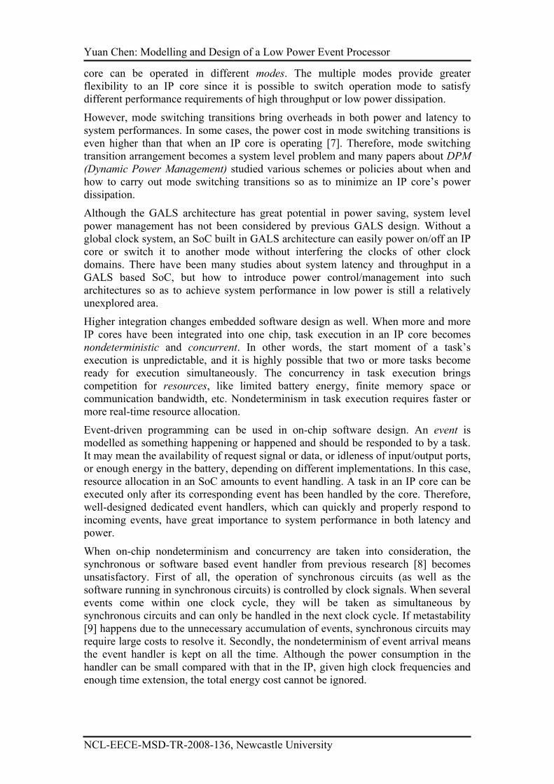
Higher degrees of transistor integration also made complex electronic devices
portable or wearable. However, the high frequency and chip density in new designs
not only bring high execution performance, but also make battery-based systems more
energy hungry. Low power technologies at different levels have been explored for
decades. Some of these, like clock gating [4], power gating [5] as well as MTCMOS
(Multi Threshold CMOS) [6] have been used in IP core design so as to reduce their
dynamic and/or leakage power dissipation. The supply voltage and/or clock frequency
can also be varied to optimize power [28]. With these low power technologies, an IP
Yuan Chen: Modelling and Design of a Low Power Event Processor
NCL-EECE-MSD-TR-2008-136, Newcastle University
core can be operated in different modes. The multiple modes provide greater
flexibility to an IP core since it is possible to switch operation mode to satisfy
different performance requirements of high throughput or low power dissipation.
However, mode switching transitions bring overheads in both power and latency to
system performances. In some cases, the power cost in mode switching transitions is
even higher than that when an IP core is operating [7]. Therefore, mode switching
transition arrangement becomes a system level problem and many papers about DPM
(Dynamic Power Management) studied various schemes or policies about when and
how to carry out mode switching transitions so as to minimize an IP core’s power
dissipation.
Although the GALS architecture has great potential in power saving, system level
power management has not been considered by previous GALS design. Without a
global clock system, an SoC built in GALS architecture can easily power on/off an IP
core or switch it to another mode without interfering the clocks of other clock
domains. There have been many studies about system latency and throughput in a
GALS based SoC, but how to introduce power control/management into such
architectures so as to achieve system performance in low power is still a relatively
unexplored area.
Higher integration changes embedded software design as well. When more and more
IP cores have been integrated into one chip, task execution in an IP core becomes
nondeterministic and concurrent. In other words, the start moment of a task’s
execution is unpredictable, and it is highly possible that two or more tasks become
ready for execution simultaneously. The concurrency in task execution brings
competition for resources, like limited battery energy, finite memory space or
communication bandwidth, etc. Nondeterminism in task execution requires faster or
more real-time resource allocation.
Event-driven programming can be used in on-chip software design. An event is
modelled as something happening or happened and should be responded to by a task.
It may mean the availability of request signal or data, or idleness of input/output ports,
or enough energy in the battery, depending on different implementations. In this case,
resource allocation in an SoC amounts to event handling. A task in an IP core can be
executed only after its corresponding event has been handled by the core. Therefore,
well-designed dedicated event handlers, which can quickly and properly respond to
incoming events, have great importance to system performance in both latency and
power.
When on-chip nondeterminism and concurrency are taken into consideration, the
synchronous or software based event handler from previous research [8] becomes
unsatisfactory. First of all, the operation of synchronous circuits (as well as the
software running in synchronous circuits) is controlled by clock signals. When several
events come within one clock cycle, they will be taken as simultaneous by
synchronous circuits and can only be handled in the next clock cycle. If metastability
[9] happens due to the unnecessary accumulation of events, synchronous circuits may
require large costs to resolve it. Secondly, the nondeterminism of event arrival means
the event handler is kept on all the time. Although the power consumption in the
handler can be small compared with that in the IP, given high clock frequencies and
enough time extension, the total energy cost cannot be ignored.
Yuan Chen: Modelling and Design of a Low Power Event Processor
NCL-EECE-MSD-TR-2008-136, Newcastle University
On the other hand, asynchronous circuits have certain advantages in event handler
design. Without clock control, an asynchronous event handler can respond to new
incoming events without delay, the probability of metastability can be greatly
reduced. Furthermore no power is wasted in an asynchronous handler when no state
change happens in the system.
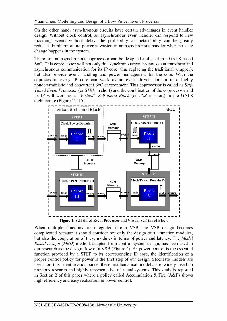
Therefore, an asynchronous coprocessor can be designed and used in a GALS based
SoC. This coprocessor will not only do asynchronous/synchronous data transform and
asynchronous communication for its IP core (thus replacing the traditional wrapper),
but also provide event handling and power management for the core. With the
coprocessor, every IP core can work as an event driven domain in a highly
nondeterministic and concurrent SoC environment. This coprocessor is called as Self-
Timed Event Processor (or STEP in short) and the combination of the coprocessor and
its IP will work as a “Virtual” Self-timed Block (or VSB in short) in the GALS
architecture (Figure 1) [10].
IP core
I
STEP I
Clock/Power Domain I ACM
Memory
ACM
Memory
ACM
Memory
ACM
Memory
SOC
events tasks eventsresultsIP core
II
STEP I
Clock/Power Domain II
events tasks
events
results
IP core
III
STEP III
Clock/Power Domain III
events tasks eventsresultsIP core
IV
STEP IV
Clock/Power Domain IV
events tasks eventsresults
Virtual Self-timed Block
STEP II
Figure 1: Self-timed Event Processor and Virtual Self-timed Block
When multiple functions are integrated into a VSB, the VSB design becomes
complicated because it should consider not only the design of all function modules,
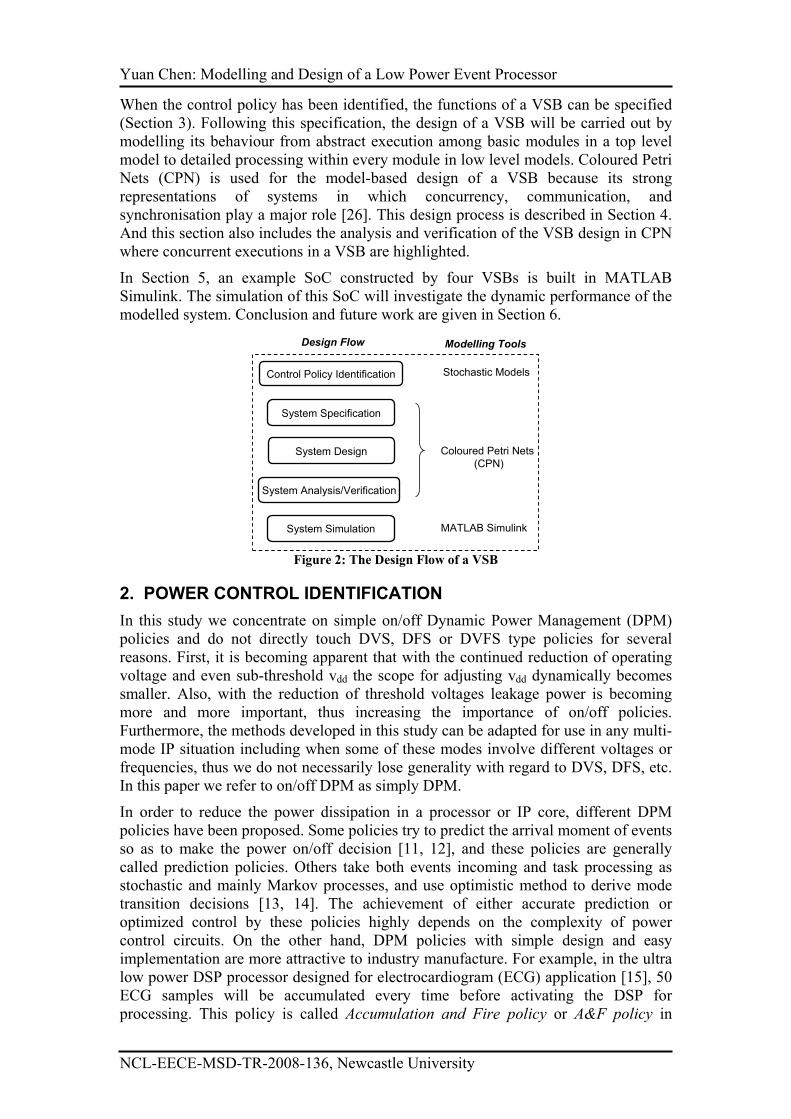
but also the cooperation of these modules in terms of power and latency. The Model
Based Design (MBD) method, adapted from control system design, has been used in
our research as the design flow of a VSB (Figure 2). As power control is the essential
function provided by a STEP to its corresponding IP core, the identification of a
proper control policy for power is the first step of our design. Stochastic models are
used for this identification since these mathematical models are widely used in
previous research and highly representative of actual systems. This study is reported
in Section 2 of this paper where a policy called Accumulation & Fire (A&F) shows
high efficiency and easy realization in power control.
Yuan Chen: Modelling and Design of a Low Power Event Processor
NCL-EECE-MSD-TR-2008-136, Newcastle University
When the control policy has been identified, the functions of a VSB can be specified
(Section 3). Following this specification, the design of a VSB will be carried out by
modelling its behaviour from abstract execution among basic modules in a top level
model to detailed processing within every module in low level models. Coloured Petri
Nets (CPN) is used for the model-based design of a VSB because its strong
representations of systems in which concurrency, communication, and
synchronisation play a major role [26]. This design process is described in Section 4.
And this section also includes the analysis and verification of the VSB design in CPN
where concurrent executions in a VSB are highlighted.
In Section 5, an example SoC constructed by four VSBs is built in MATLAB
Simulink. The simulation of this SoC will investigate the dynamic performance of the
modelled system. Conclusion and future work are given in Section 6.
Control Policy Identification
System Specification
System Design
System Analysis/Verification
System Simulation
Design Flow Modelling Tools
Stochastic Models
Coloured Petri Nets
(CPN)
MATLAB Simulink
Figure 2: The Design Flow of a VSB
2. POWER CONTROL IDENTIFICATION
In this study we concentrate on simple on/off Dynamic Power Management (DPM)
policies and do not directly touch DVS, DFS or DVFS type policies for several
reasons. First, it is becoming apparent that with the continued reduction of operating
voltage and even sub-threshold vdd the scope for adjusting vdd dynamically becomes
smaller. Also, with the reduction of threshold voltages leakage power is becoming
more and more important, thus increasing the importance of on/off policies.
Furthermore, the methods developed in this study can be adapted for use in any multi-
mode IP situation including when some of these modes involve different voltages or
frequencies, thus we do not necessarily lose generality with regard to DVS, DFS, etc.
In this paper we refer to on/off DPM as simply DPM.
In order to reduce the power dissipation in a processor or IP core, different DPM
policies have been proposed. Some policies try to predict the arrival moment of events
so as to make the power on/off decision [11, 12], and these policies are generally
called prediction policies. Others take both events incoming and task processing as
stochastic and mainly Markov processes, and use optimistic method to derive mode
transition decisions [13, 14]. The achievement of either accurate prediction or
optimized control by these policies highly depends on the complexity of power
control circuits. On the other hand, DPM policies with simple design and easy
implementation are more attractive to industry manufacture. For example, in the ultra
low power DSP processor designed for electrocardiogram (ECG) application [15], 50
ECG samples will be accumulated every time before activating the DSP for
processing. This policy is called Accumulation and Fire policy or A&F policy in
Yuan Chen: Modelling and Design of a Low Power Event Processor
NCL-EECE-MSD-TR-2008-136, Newcastle University
short, which is similar to the integrate and fire mechanism found in biological neural
systems [16].
When A&F policy is implemented, a sleeping IP core will not be activated
immediately when a new event arrives (and its corresponding task is ready for
processing). Instead we accumulate ready tasks by continuously accumulating
incoming events. The accumulation will continue until a certain limit N is reached (N
is called accumulation limit). The IP core is then woken up to batch process
accumulated tasks. When N=1, a single ready task can trigger a sleeping core and
A&F policy in this case is the “greedy” policy [17] or “eager” policy [13]. Compared
with previous policies, A&F has a much simpler hardware realization. In this section,
we build Markov models to analyze the A&F policy. Based on the results of this
analysis, we then argue that A&F has such desirable properties as efficiency of power
saving and flexibility of power-latency tradeoffs.
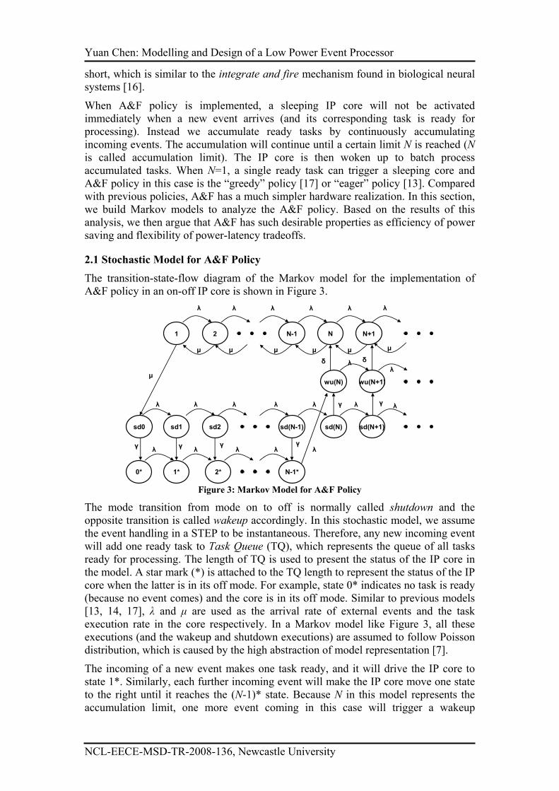
2.1 Stochastic Model for A&F Policy
The transition-state-flow diagram of the Markov model for the implementation of
A&F policy in an on-off IP core is shown in Figure 3.
wu(N+1)wu(N)
sd(N-1) sd(N)
0*
1 2
1* 2*
N-1 N N+1
N-1*
sd0 sd1 sd(N+1)
λ λ λ λ
λ λ λ λ λ
λ λ λ λ λ
µ µ µ µ µ
λ
λ
λ
λ
λ
µ
sd2
λ
µ
γ
δ
γ
δ
γγγγ
Figure 3: Markov Model for A&F Policy
The mode transition from mode on to off is normally called shutdown and the
opposite transition is called wakeup accordingly. In this stochastic model, we assume
the event handling in a STEP to be instantaneous. Therefore, any new incoming event
will add one ready task to Task Queue (TQ), which represents the queue of all tasks
ready for processing. The length of TQ is used to present the status of the IP core in
the model. A star mark (*) is attached to the TQ length to represent the status of the IP
core when the latter is in its off mode. For example, state 0* indicates no task is ready
(because no event comes) and the core is in its off mode. Similar to previous models
[13, 14, 17], λ and µ are used as the arrival rate of external events and the task
execution rate in the core respectively. In a Markov model like Figure 3, all these
executions (and the wakeup and shutdown executions) are assumed to follow Poisson
distribution, which is caused by the high abstraction of model representation [7].
The incoming of a new event makes one task ready, and it will drive the IP core to
state 1*. Similarly, each further incoming event will make the IP core move one state
to the right until it reaches the (N-1)* state. Because N in this model represents the
accumulation limit, one more event coming in this case will trigger a wakeup
Yuan Chen: Modelling and Design of a Low Power Event Processor
NCL-EECE-MSD-TR-2008-136, Newcastle University
transition, which is represented by state wu(N). Parameter δ is used to describe the
non instantaneous time cost in wakeup transitions (and γ is used to describe that in
shutdown transitions, which is introduced later). Because no task processing is done
in the wakeup transition, the task accumulation may increase if some new events
come when the wakeup transition is in progress. In our model, state wu(N+i) is used
to represent the state when an arbitrary number of events come during the wakeup
transition. The usage of infinite number of wakeup states wu(N+i) enables our model
to describe the behaviour of the IP core in greater accuracy.
Suppose there are (N+i) tasks accumulated when the wakeup transition is completed,
the IP core moves to the state N+i for task processing. When any task execution is
completed, the core will move one state to the left. When the execution of the last task
in the TQ is completed (system leaving state 1), a shutdown transition starts,
described by shutdown states sd0, sd1 etc. The IP core can move to its off mode when
no more than N events come during the shutdown transition, otherwise the core has to
be woken up immediately when the shutdown transition is completed.
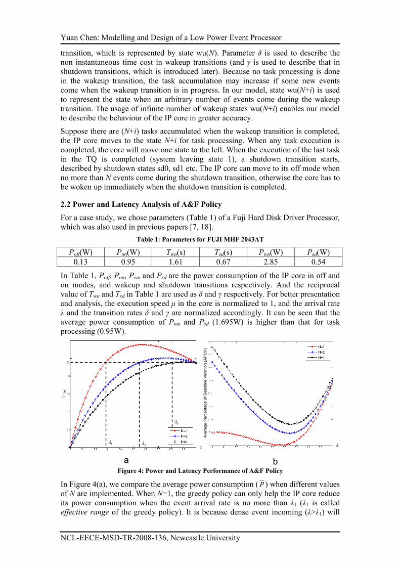
2.2 Power and Latency Analysis of A&F Policy
For a case study, we chose parameters (Table 1) of a Fuji Hard Disk Driver Processor,
which was also used in previous papers [7, 18].
Table 1: Parameters for FUJI MHF 2043AT
Poff(W) Pon(W) Twu(s) Tsd(s) Pwu(W) Psd(W)
0.13 0.95 1.61 0.67 2.85 0.54
In Table 1, Poff, Pon, Pwu and Psd are the power consumption of the IP core in off and
on modes, and wakeup and shutdown transitions respectively. And the reciprocal
value of Twu and Tsd in Table 1 are used as δ and γ respectively. For better presentation and analysis, the execution speed µ in the core is normalized to 1, and the arrival rate
λ and the transition rates δ and γ are normalized accordingly. It can be seen that the
average power consumption of Pwu and Psd (1.695W) is higher than that for task
processing (0.95W).
λ
P)(W
wP
1λ2λ
3λ
Average Percentage of Deadline Violation (APDV)
λ
a b Figure 4: Power and Latency Performance of A&F Policy
In Figure 4(a), we compare the average power consumption (P ) when different values
of N are implemented. When N=1, the greedy policy can only help the IP core reduce
its power consumption when the event arrival rate is no more than λ1 (λ1 is called
effective range of the greedy policy). It is because dense event incoming (λ>λ1) will
Yuan Chen: Modelling and Design of a Low Power Event Processor
NCL-EECE-MSD-TR-2008-136, Newcastle University
cause frequent wakeup and shutdown transitions which will cost more power
overheads than power saving. With the increase of N, A&F policy can not only
increase its effective range continuously, but also reduces P for across this range.
Furthermore, the flexibility of A&F policy can be demonstrated by Figure 4(b) where
system latency caused by A&F policy with different N values is presented. In many
SoC design, some deadline is given to a task and the execution of the task is thought
to add system latency only when it can not be completed before the deadline
requirement. Therefore different from previous studies, we use the concept of
Average Percentage of Deadline Violation (APDV) to measure system latency. When
the deadline for every task in the IP core is set to 10 times the average execution
period (Deadline=10/µ), Figure 4(b) shows APDV value will increase with the rise of
N. Therefore, different power-latency tradeoff in A&F policy is realized by simply
adjusting the value of N. This characteristic makes A&F policy more flexible than
other DPM policies.
Actually A&F policy shows its efficiency and flexibility not only when it is
cooperated with on/off IP cores, but also when it is implemented with IP cores with
multiple modes for finer control [19]. Furthermore, the simple A&F policy requires
little event processing power for a STEP compared with for instance a prediction
policy. Therefore, the A&F policy that is specified in this section will serve as the
power control mechanism used in our STEP design.
3. VSB Specification
According to the stochastic models given in Section 2, an IP core can be represented
by two factors: Tasks and Modes. Although an infinite length of task queue is
assumed in the stochastic model analysis, an IP core can only provide a finite number
of task services. A mode defines the power dissipation as well as the processing speed
in the core. With such knowledge, we can give a basic functional specification of a
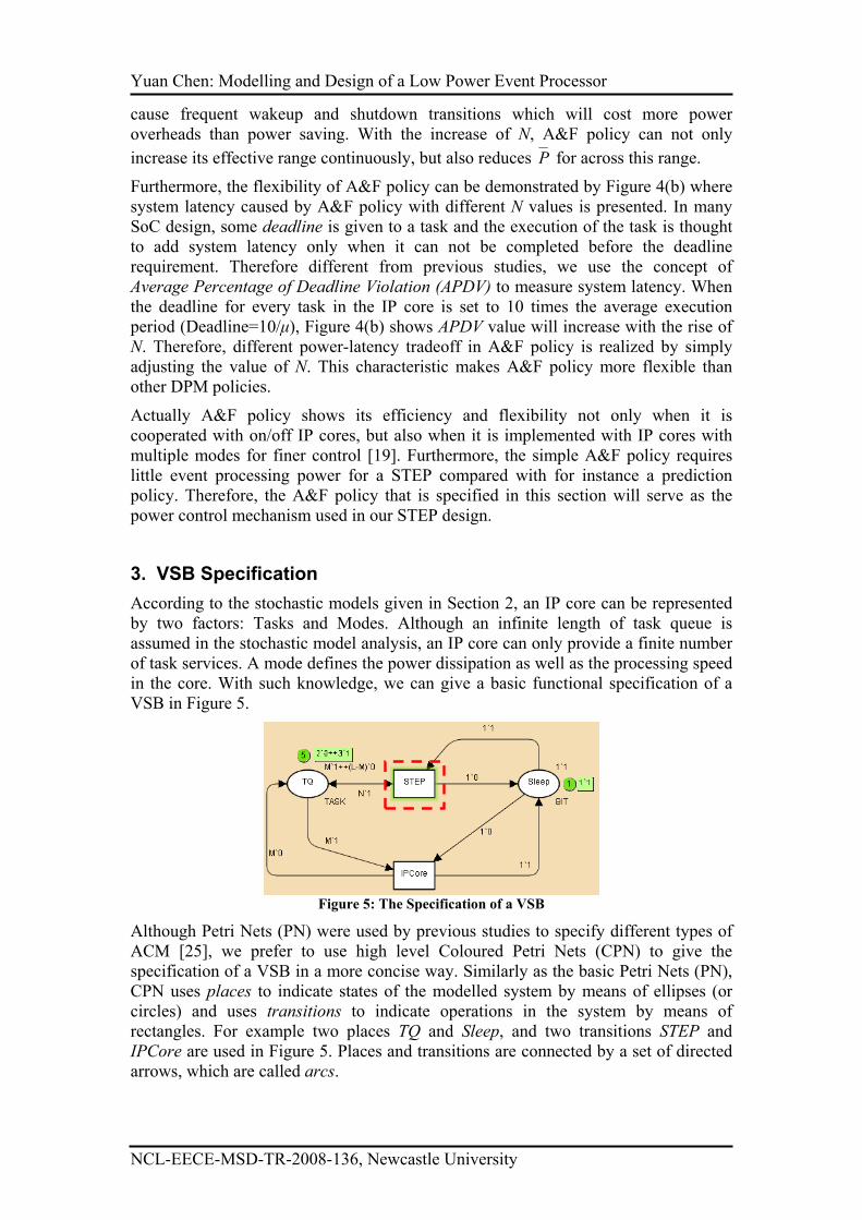
VSB in Figure 5.
Figure 5: The Specification of a VSB
Although Petri Nets (PN) were used by previous studies to specify different types of
ACM [25], we prefer to use high level Coloured Petri Nets (CPN) to give the
specification of a VSB in a more concise way. Similarly as the basic Petri Nets (PN),
CPN uses places to indicate states of the modelled system by means of ellipses (or
circles) and uses transitions to indicate operations in the system by means of
rectangles. For example two places TQ and Sleep, and two transitions STEP and
IPCore are used in Figure 5. Places and transitions are connected by a set of directed
arrows, which are called arcs.
Yuan Chen: Modelling and Design of a Low Power Event Processor
NCL-EECE-MSD-TR-2008-136, Newcastle University
A place in a CPN/PN model is used to hold tokens, which are represented by the small
dots next to each place. An arbitrary distribution of tokens in places is called a
marking. Different from PN, each token in CPN is attached with some data value
(called token colour). The data value may be of an arbitrarily complex type. For a
given place, all tokens must share the same colour. This colour is called the colour set
of the place which is written in the right bottom corner of the place.
In CPN, two operators ++ and ` are used for the construction of a multi-set consisting
of token colours. The infix operator ` takes a nonnegative integer to specify the
number of appearances of the element provided as the right argument. The ++ takes
two multi-sets as arguments and returns their union (sum). For example, the tokens
2`0++3`1 in the TQ place describe two tokens with colours (values) of ‘0’ and three
tokens with value of ‘1’ respectively (In this paper, a pair of quotations ‘’ will be used
to quote a colour value when it may be confused with the token number).
The VSB specified in Figure 5 presents an on-off IP core under A&F power control.
Two colours have been declared in this figure. Colour BIT is declared to describe
binary information and have only values ‘0’ and ‘1’. It is the set colour of the place
Sleep. Initially a ‘1’ token is given to the Sleep place (The initial token of a place is
described in the upper right side of the place), which indicates the IP core is in its off
mode.
The other colour declared in the figure is called TASK, which represents tasks that can
be executed in the IP core. In this high-level specification, all tasks are taken as
identical and the TASK colour is declared as BIT colour whose token value represents
whether the task is ready for processing (value ‘1’) or not (value ‘0’). The TASK
colour is the set colour of the TQ place (means Task Queue). Since an IP core can
only perform a finite number of tasks, two integer constants L and M represent the
total number of tasks of the core and the number of valid tasks of the core
respectively. Therefore, the initial marking of M`1++(L-M)`0 in the TQ place
indicates initially M out of L tasks in the core are ready for processing. When M and L
are specified as 3 and 5 respectively, the token held in the TQ becomes 2`0++3`1.
A transition is enabled if and only if each of its input places contains at least the
number of tokens prescribed by the expression of the corresponding input arc. When a
transition is enabled, the corresponding move may take place, which is called the
occurrence of the transition. As a consequence, tokens from the input places will be
removed from the input places and added to the output places after the execution of an
occurrence.
The STEP transition is used to describe the power/task control given to the IP core,
i.e. the actions performed by the STEP. The expression in the arc from the Sleep place
to the STEP transition is written as 1`1, which means this transition is only enabled
when the token value in the Sleep place is ‘1’. It indicates the power control is given
to the IP core only when it is in its off mode. The TQ place and the STEP transition
are connected by a double-headed arc. A double headed arc is shorthand for two
directed arcs in opposite directions between two nodes which have the same arc
expression. The integer constant N (N≤L) is used to represent the accumulation limit
of A&F policy which is implemented in the STEP. Therefore, when N is specified to
2, the STEP transition is enabled (which is highlighted by a dotted rectangle) and its
occurrence will change the token colour in the Sleep place to ‘0’. This occurrence
indicates the IP core is activated when there are at least N tasks accumulated.
Yuan Chen: Modelling and Design of a Low Power Event Processor
NCL-EECE-MSD-TR-2008-136, Newcastle University
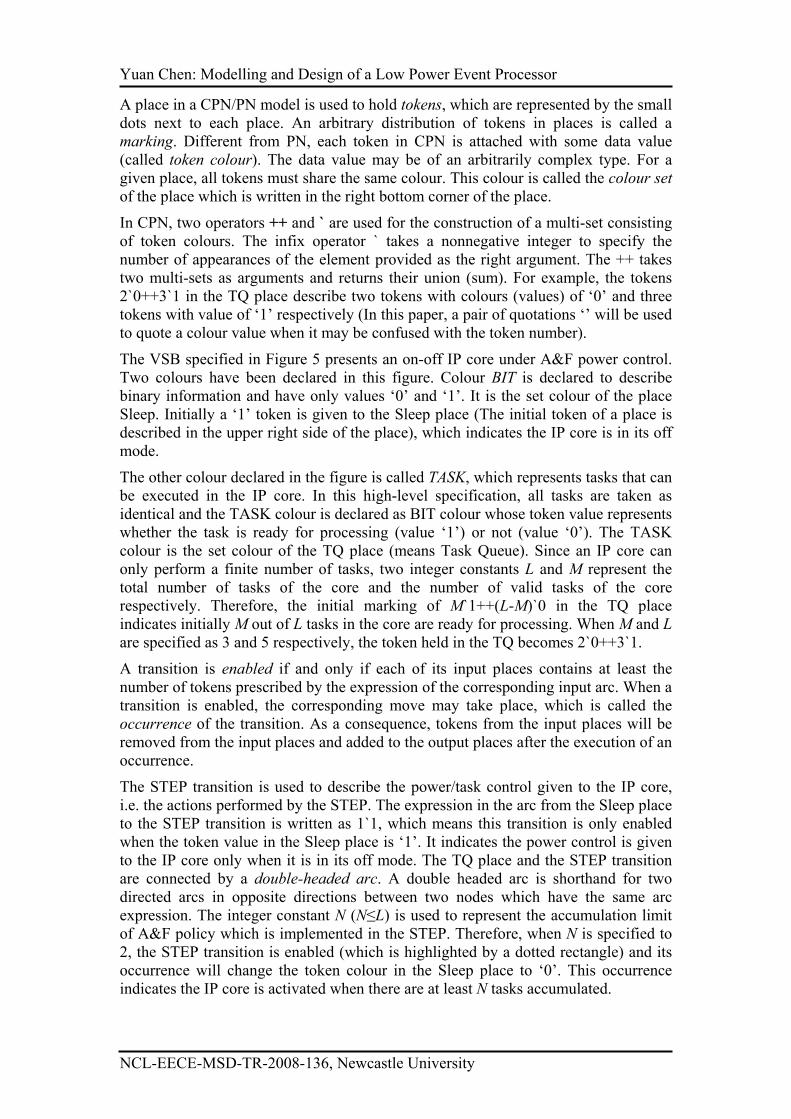
When the token in the Sleep place becomes ‘0’, the IPCore transition is enabled and
its occurrence will first reset all ‘1’ tokens in the TQ place to ‘0’, and then toggle the
token in the Sleep place to ‘1’. This occurrence describes the processing of all ready
tasks in the activated IP core, and the shutting down of the core afterwards when no
tasks are ready.
Figure 6: New Specification of a VSB
Although the model in Figure 5 specifies the basic function in a STEP and an IP core
in a VSB, it only represents an isolated computation block without interactions with
its environment. In Figure 6, we present the relationship between a VSB and its SoC
environment. Transitions InEnv and OutEnv represent the SoC environment and dark
shade is used in these two places so as to differentiate them from other
places/transitions which represent a VSB. The occurrence of the InEnv transition will
update a ‘0’ token in the TQ place to ‘1’, which represents some task provided by the
IP core is requested by an event coming from the environment.
One place RT is added in this figure, and the token held in this place represents the
result of task executions in an IP core. Any token in this place will enable the OutEnv
transition, which describes the effect of the execution in the current VSB to its
environment.
Therefore, the specification in Figure 5 presents the essential processing in a VSB: A
STEP will accumulate at least N tasks to activate a sleeping IP core, and an active IP
core will shut down itself when all task executions are completed. This specification
will inspire the VSB design and analysis in Section 4.
4. VSB DESIGN AND ANALYSIS IN CPN
In Section 2 and 3, we assume the event handling processing in a STEP is
instantaneous. Therefore, no representation of event handling is given in the
specification. Besides, the VSB presented in the specification is isolated from its SoC
environment. All these simplifications will be removed in the VSB design in this
section. A top-down design will be realized by a group of hierarchical CPN models of
a VSB. We will first give a top level model to present all necessary components in a
VSB and their connections, and then extend the design of every component in
different detailed CPN models.
4.1 The Top Level CPN Model of a VSB architecture design
Yuan Chen: Modelling and Design of a Low Power Event Processor
NCL-EECE-MSD-TR-2008-136, Newcastle University
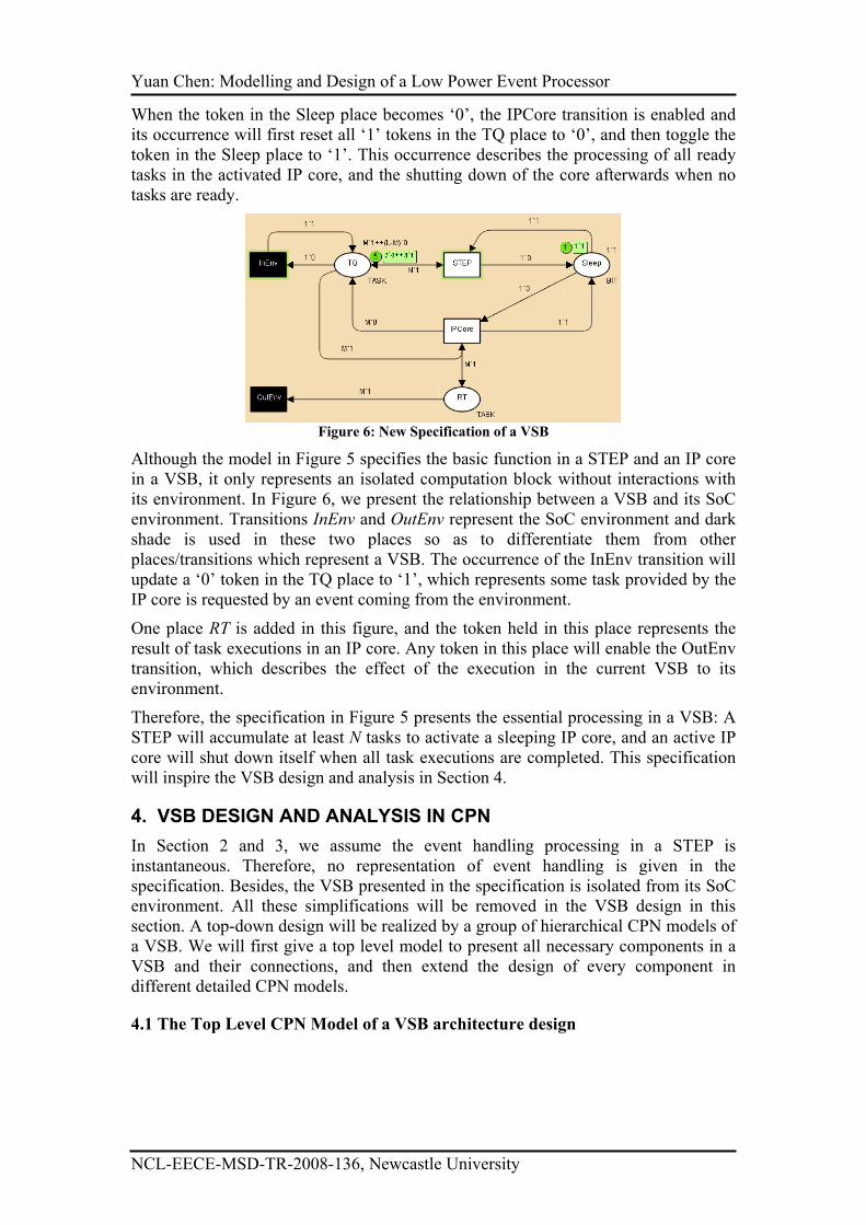
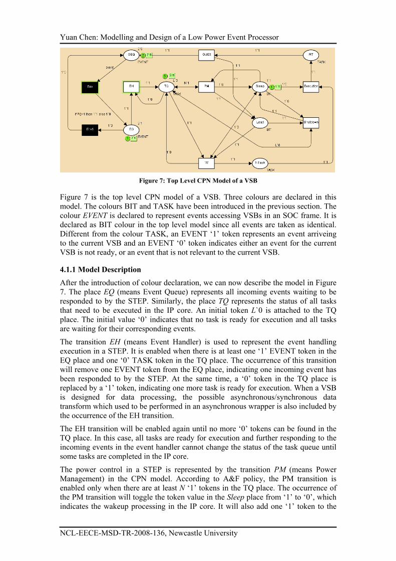
Figure 7: Top Level CPN Model of a VSB
Figure 7 is the top level CPN model of a VSB. Three colours are declared in this
model. The colours BIT and TASK have been introduced in the previous section. The
colour EVENT is declared to represent events accessing VSBs in an SOC frame. It is
declared as BIT colour in the top level model since all events are taken as identical.
Different from the colour TASK, an EVENT ‘1’ token represents an event arriveing
to the current VSB and an EVENT ‘0’ token indicates either an event for the current
VSB is not ready, or an event that is not relevant to the current VSB.
4.1.1 Model Description
After the introduction of colour declaration, we can now describe the model in Figure
7. The place EQ (means Event Queue) represents all incoming events waiting to be
responded to by the STEP. Similarly, the place TQ represents the status of all tasks
that need to be executed in the IP core. An initial token L`0 is attached to the TQ
place. The initial value ‘0’ indicates that no task is ready for execution and all tasks
are waiting for their corresponding events.
The transition EH (means Event Handler) is used to represent the event handling
execution in a STEP. It is enabled when there is at least one ‘1’ EVENT token in the
EQ place and one ‘0’ TASK token in the TQ place. The occurrence of this transition
will remove one EVENT token from the EQ place, indicating one incoming event has
been responded to by the STEP. At the same time, a ‘0’ token in the TQ place is
replaced by a ‘1’ token, indicating one more task is ready for execution. When a VSB
is designed for data processing, the possible asynchronous/synchronous data
transform which used to be performed in an asynchronous wrapper is also included by
the occurrence of the EH transition.
The EH transition will be enabled again until no more ‘0’ tokens can be found in the
TQ place. In this case, all tasks are ready for execution and further responding to the
incoming events in the event handler cannot change the status of the task queue until
some tasks are completed in the IP core.
The power control in a STEP is represented by the transition PM (means Power
Management) in the CPN model. According to A&F policy, the PM transition is
enabled only when there are at least N ‘1’ tokens in the TQ place. The occurrence of
the PM transition will toggle the token value in the Sleep place from ‘1’ to ‘0’, which
indicates the wakeup processing in the IP core. It will also add one ‘1’ token to the
Yuan Chen: Modelling and Design of a Low Power Event Processor
NCL-EECE-MSD-TR-2008-136, Newcastle University
load place, which means the IP core will load a new task for execution when the
wakeup processing is completed. According to the arc from the Sleep place to the PM
transition, the PM transition is only enabled when the token value in the Sleep place is
‘1’. It is such designed because A&F is useful only when the IP core is sleeping.
Disabling the execution in the PM after the IP core is activated will further reduce the
power dissipation in a VSB.
The nondeterministic incoming of events make it highly possible that several tasks
can become ready before the IP core is woken up. In this case, some scheduling
execution is necessary to select one task from all the ready ones for the IP core’s
execution. Although task scheduling is provided by many IP cores, a task manager is
designed as a component of a STEP to provide scheduling service. It is not only
because hardware scheduling can be many times faster than software scheduling, but
also because this design means both task scheduling in the STEP and wakeup
processing in the IP core are carried out in parallel for better system latency and
power dissipation.
In Figure 7, the transition TM is used to represent the execution in the task manager.
This transition is enabled when there are more than one TASK ‘1’ token in the TQ
place and one BIT ‘1’ token in the load place. Because all tasks are treated as
identical in the top level model, the occurrence of this transition will add one TASK
‘1’ token to the NTask (means New Task) place, indicating a randomly chosen task is
loaded to the IP core. At the same time, one TASK ‘0’ token is added to the TQ place
indicating the chosen task in the NTask place has already progressed to the next step.
When one TASK token is available in the NTask place, the Execution transition is
enabled and the occurrence of this transition indicates the execution of the current
task in the IP core and it will add one TASK ‘1’ token to the RT (means Result Task)
place. Generally speaking, the completion of one task execution will either release
some system resources like I/O port or data bus, or generate some new data or signals.
In most cases, the released resources or generated data in one VSB can work as a new
event to trigger some other task in the SoC, probably in other VSBs. Therefore, a new
component of STEP, named as output controller, is needed to prepare a new event
when the execution of the current task is completed. In the top level model, the
transition OutCt is used to represent the executions in the output controller. Its
occurrence will add one EVENT ‘1’ token to the OEQ (means Output Event Queue)
place where events will be sent to the SoC environment. The occurrence of OutCt
transition will also add one token to the Load place which enables the TM transition
to choose another task for the IP core’s execution. Note that this cycle implies an
assumption of fully sequential execution in the IP core, but can easily be extended to
situations when the IP core can handle execution concurrency.
When a new BIT token in the load place is generated but finding no TASK ‘1’ token
available in the TQ place, the Shutdown transition will be enabled since ready tasks
have all been executed. Its occurrence will toggle the token in the Sleep place to ‘1’
which means the IP core has been shut down.
4.1.2 Environmental Set Description
All places and transitions introduced so far construct the top level model of a VSB. In
order to check the behaviour of the model and verify the properties, some extra places
and transitions are added so as to simulate the asynchronous environment of an SoC.
Therefore, the entire top level model can represent an enclosed system. These places
Yuan Chen: Modelling and Design of a Low Power Event Processor
NCL-EECE-MSD-TR-2008-136, Newcastle University
and transitions are highlighted by dark shade so as to differentiate from their
counterparts describing a VSB.
Transition Env (means environment) is used to describe event transferring in an SoC.
The occurrence of the Env transition indicates the event generated from the current
VSB is transferred to its SoC environment. It will be used in some other VSB to
enable some task’s execution. And the execution of the task will also generate some
new events. Eventually this relay of “event transfer – task execution – event transfer”
may generate some event to enable a task in the current VSB in turn again, but the
time span cost in this relay is nondeterministic.
A CPN function P() and a transition Env1 are used to model the nondeterministic
characteristic of event relays. The CPN function P() is defined as:
fun P() = poisson (2.5)
This function uses the random number generator poisson provided by CPN Tools [21]
to generate a random integer number which follows Poisson distribution. The number
2.5 in the function declaration is the rate λ in the Poisson distribution and can be
changed according to the feature of the implementation environment.
The expression of the arc from the transition Env to the place EQ is written as “if
P()>1 then 1`1 else 1`0”. Therefore, the value of the token generated by the Env
transition’s occurrence depends on the result of P() function. If the function result is
less than 1, an EVENT ‘0’ token is added to the EQ place indicating the event relay is
not completed since an EVENT ‘0’ token can not enable the EH transition. Instead, it
will enable the Env1 transition and the latter’s occurrence will add one EVENT ‘0’
token to the OEQ place. When an EVENT type variable event is used in the
expression of arc from the OEQ place to the Env transition, the latter transition will be
enabled no matter what value the token in the OEQ has. Therefore, the token loop in
OEQ-Env-EQ-Env1-OEQ represents the event relay in the SoC environment and the
moment to jump out of the loop depends on the random result generated by the P()
function. When the P() result becomes bigger than 1, an EVENT ‘1’ token added to
the EQ place will enable occurrences in the current VSB. We use this token loop and
its non-deterministic exit to model the non-deterministic nature of event distribution
within an SoC and its effect on any single VSB because at this stage we have no
application-specific system level information.
4.1.3 Simulation
CPN Tools [21] is the computer aid software for CPN modelling and analysis. This
software provides easy editing, simulation, state space analysis, and performance
analysis of CPN models. In this section, we use CPN Tools to build CPN models of a
VSB and simulation and state space checking are used for analysis and error
checking. Initially we set one ‘0’ token to the Sleep place suggesting the IP core is
inactive. Constant L is set to 5, and five ‘0’ TASK tokens are given to the TQ place
indicating none of the five tasks are ready for execution. Two EVENT ‘1’ tokens are
set to the EQ place showing two incoming events are waiting to be responded to by
the STEP. Even when the two events are responded to, the IP core cannot be woken
up since N is set to 3. At the same time, two EVENT ‘0’ tokens are added to the OEQ
place indicating two events are relaying in the environment. Therefore, the activation
of the IP core needs the arrival of at least one EVENT ‘1’ token to be added to the
EQ.
Yuan Chen: Modelling and Design of a Low Power Event Processor
NCL-EECE-MSD-TR-2008-136, Newcastle University
With the initial marking, we can observe the behaviour of the top level model using
the simulation tool by CPN Tools. All concurrent executions in the system are shown
with simulation steps. Sometimes more than one transition is enabled in one step. This
simultaneous transition enabling describes the concurrent processing in the
corresponding system. The occurrence sequence of multi enabled transitions is
random, which represents the nondeterminism in their modelled operations. Since
different occurrence sequences may bring different markings, CPN models are highly
representative for the behaviour of a system under nondeterministic and concurrency.
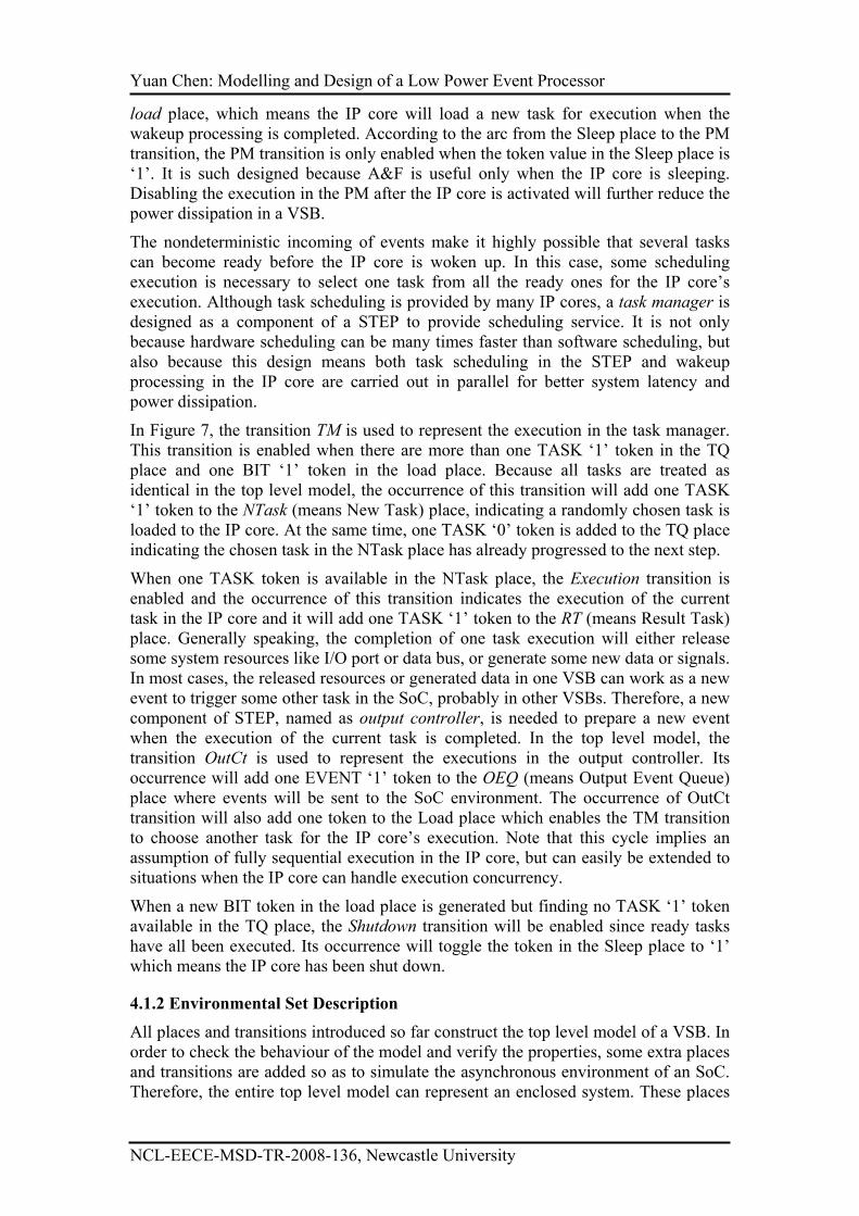
Some typical concurrent executions are shown in Figure 8 where every enabled
transition is highlighted by a dotted rectangle. Figure 8 (a) is about the concurrent
executions between the current VSB (The EH transition) and the environment (The
Env transition). Figure 8(b) indicates the concurrent executions among different
components of a STEP (The EH and TM transitions). The concurrent executions
between a STEP (The EH transition) and its IP core (The Execution transition) are
shown in Figure 8(c).
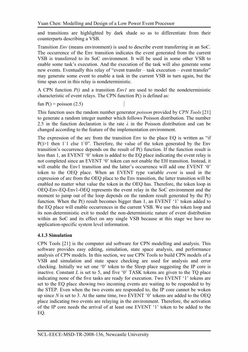
The simulation can also help users to correct errors in their model design. For
example, one double-headed arc is used to connect the Shutdown transition and the
TQ place because all ‘0’ TASK tokens will be checked but not consumed when the
Shutdown transition occurs. However, designers might miss the arc directing from the
Shutdown transition to the TQ place (Figure 9) and the consumption of TASK ‘0’
tokens in the occurrence of Shutdown transition will make further enabling in the EH
transition impossible.
(b) Step =23
(c) Step =6
(a) Step =0
Figure 8: The simulation result of the CPN model
If simulation is carried out with the incorrect top level model, it will stop after a
certain number of steps because in that case no more transitions will be enabled
(called dead marking or dead lock). Therefore, a dead marking in the simulation is
used to detect an error. However, because of the randomness brought by the function
P(), this simulation termination may not happen within a few steps. Five simulations
have been carried out when the model has the given error. In these simulations, the
CPN Tools took 103, 202, 159, 394, 941 steps respectively to reach the dead marking.
Since simulations cannot guarantee the finding of any particular malfunction, we need
other more reliable function tool to prove the correctness of the model.
Yuan Chen: Modelling and Design of a Low Power Event Processor
NCL-EECE-MSD-TR-2008-136, Newcastle University
Figure 9: A Possible Error in Top Level Model Design
4.1.4 State Space Checking
The state space tool provided by CPN Tools will check all possible executions of the
model and present the properties of the full state spaces of the model in a statistical
report. Therefore, state space checking has been used on the top level model (as well
as other CPN models in the following sections) for error checking and property
verification.
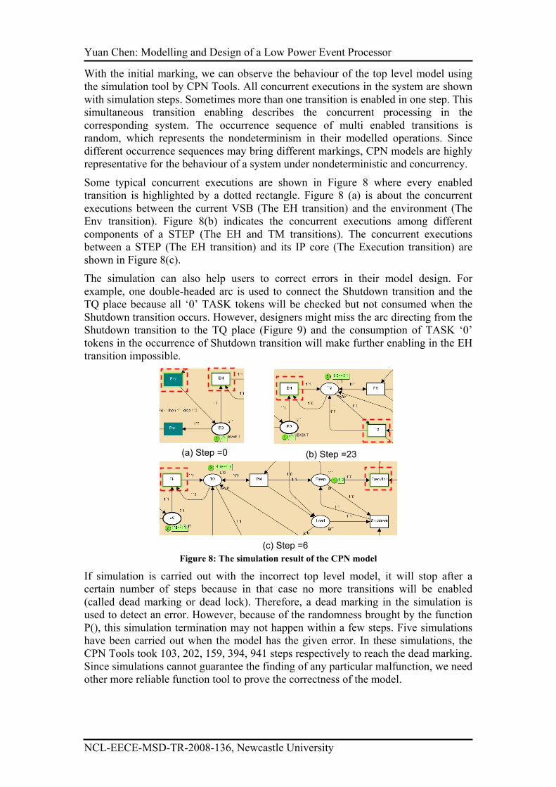
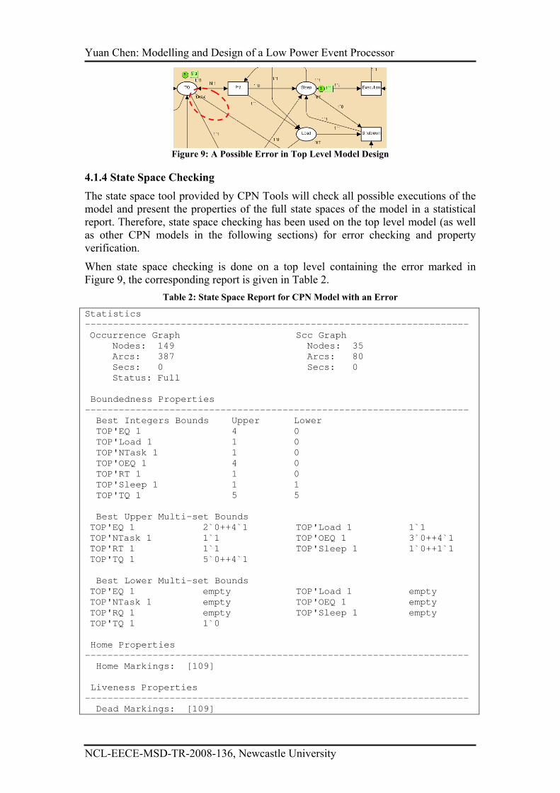
When state space checking is done on a top level containing the error marked in
Figure 9, the corresponding report is given in Table 2.
Table 2: State Space Report for CPN Model with an Error
Statistics
--------------------------------------------------------------------
Occurrence Graph Scc Graph
Nodes: 149 Nodes: 35
Arcs: 387 Arcs: 80
Secs: 0 Secs: 0
Status: Full
Boundedness Properties
--------------------------------------------------------------------
Best Integers Bounds Upper Lower
TOP'EQ 1 4 0
TOP'Load 1 1 0
TOP'NTask 1 1 0
TOP'OEQ 1 4 0
TOP'RT 1 1 0
TOP'Sleep 1 1 1
TOP'TQ 1 5 5
Best Upper Multi-set Bounds
TOP'EQ 1 2`0++4`1 TOP'Load 1 1`1
TOP'NTask 1 1`1 TOP'OEQ 1 3`0++4`1
TOP'RT 1 1`1 TOP'Sleep 1 1`0++1`1
TOP'TQ 1 5`0++4`1
Best Lower Multi-set Bounds
TOP'EQ 1 empty TOP'Load 1 empty
TOP'NTask 1 empty TOP'OEQ 1 empty
TOP'RQ 1 empty TOP'Sleep 1 empty
TOP'TQ 1 1`0
Home Properties
--------------------------------------------------------------------
Home Markings: [109]
Liveness Properties
--------------------------------------------------------------------
Dead Markings: [109]

Yuan Chen: Modelling and Design of a Low Power Event Processor
NCL-EECE-MSD-TR-2008-136, Newcastle University
Dead Transitions Instances: None
Live Transitions Instances: None
A full state space is a directed graph, where there is a node for each reachable
marking and an arc for each occurring binding element. Therefore, the first part of the
state space report is state space statistics telling how large the state space is. The next
two parts of the state space report contain information about the boundedness
properties. The boundedness properties tell how many (and which) tokens a place
may hold. The best upper integer bounds for a place specify the maximal number of
tokens that can reside on each place in any reachable marking. For the place EQ, it
holds four EVENT ‘1’ or two EVENT ‘0’ tokens at most. The best lower integer
bounds for a place specify the minimal number of tokens that can reside on each place
in any reachable marking.
Following the boundedness properties are the home properties, which are about the
reachable property of markings and transitions in the model. A home marking is a
marking which can be reached from any reachable marking. The report of the
example model shows one home marking exists whose index is 109. A dead marking
is a marking which no binding elements are enabled. The current report shows the
home marking is a dead marking.
A transition is live if from any reachable marking we can always find an occurrence
sequence containing the transition. A transition is dead if there is no reachable
marking in which it is enabled. The report shows that all transitions in the model are
neither live nor dead. In other words, they can be reached from some initial markings
but cannot from others.
The information given in the report can help users have a more specific and thorough
understanding of their models so as to correct errors which cannot be easily found by
simulation and improve the performance of the corresponding systems.
Because no dead transition exists in the model, it means all transitions can be enabled
at least once. However the occurrence of some transition causes an abnormal marking
which makes no more transitions can be enabled since then. Since the dead marking is
a home marking, it means this abnormal marking will always happen no matter what
occurrence sequences may happen. This analysis can help the designer finally find the
error in the arc between Shutdown transition and the TQ place. When the error is
removed from the model, the corresponding state space report is given in Table 3(all
identical items with the report in Table 2 are omitted).
Table 3: State Space Report for a Correct CPN Model
Statistics
--------------------------------------------------------------------
Occurrence Graph Scc Graph
Nodes: 177 Nodes: 1
Arcs: 471 Arcs: 0
Secs: 1 Secs: 0
Status: Full
Boundedness Properties
--------------------------------------------------------------------
…
Home Properties
--------------------------------------------------------------------
Home Markings: All
Yuan Chen: Modelling and Design of a Low Power Event Processor
NCL-EECE-MSD-TR-2008-136, Newcastle University
Liveness Properties
--------------------------------------------------------------------
Dead Markings: None
Dead Transitions Instances: None
Live Transitions Instances: All
4.1.5 The Extension of Top Level Model
In this section, we present a top level CPN model of a VSB (including a STEP and an
IP core). Although abstract, this model clearly presents the basic architecture and
execution flow in a VSB. The integration of A&F policy for power control is also
specified in the model. Both simulation and state space function tools provided by
CPN Tools are used to check the correctness of the model.
The abstract declaration of both EVENT and TASK colours make the top level model
maintain robustness when events are specified by different concepts in various
implementations. However, it also prevents representing the execution details in the
model. For example, the top level model gives no information about how incoming
events are handled in the EH and how scheduling is carried out in the TM. Refining to
lower level models is needed to clarify the design. In these models EVENT and
TASK colours are re-declared. In the following sections, four CPN models are
designed, each of which focuses on one component of a STEP and works as the
extension of the top level CPN model.
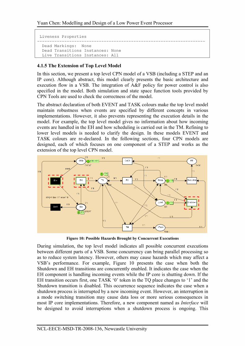
Figure 10: Possible Hazards Brought by Concurrent Executions
During simulation, the top level model indicates all possible concurrent executions
between different parts of a VSB. Some concurrency can bring parallel processing so
as to reduce system latency. However, others may cause hazards which may affect a
VSB’s performance. For example, Figure 10 presents the case when both the
Shutdown and EH transitions are concurrently enabled. It indicates the case when the
EH component is handling incoming events while the IP core is shutting down. If the
EH transition occurs first, one TASK ‘0’ token in the TQ place changes to ‘1’ and the
Shutdown transition is disabled. This occurrence sequence indicates the case when a
shutdown process is interrupted by a new incoming event. However, an interruption in
a mode switching transition may cause data loss or more serious consequences in
most IP core implementations. Therefore, a new component named as Interface will
be designed to avoid interruptions when a shutdown process is ongoing. This
Yuan Chen: Modelling and Design of a Low Power Event Processor
NCL-EECE-MSD-TR-2008-136, Newcastle University
component, together with the event handler (EH), the power manager (PM), the task
manager (TM), the output controller (OutCt), constitutes the basic structure of a
STEP.
4.2 The CPN Model of the Event Handler Component
In this section, we try to model and specify executions in the event hander component
of a STEP. In the top level model, every occurrence of the EH transition can only
consume one EVENT token in the EQ place, which means all incoming events from
different communication Channels must wait in a queue to be responded by the STEP
and therefore arbiter(s) become indispensible when events may arrive simultaneously.
The direct use of arbiters will bring cost in both power dissipation and latency. A
better solution should enable multiple events to be handled in parallel.
Moreover, the occurrence of the EH transition in the top level model will update the
value of one task token from ‘0’ to ‘1’, which means every incoming event will make
one corresponding task ready for execution. However, this is not true in the
implementation of STEPs with multiple input Channels. Although events from the
same Channel always indicate different tasks in an IP core (otherwise two events can
be taken as one with double amount of information), events from different Channels
are highly possible to indicate the execution of the same task (but with different
information like data for operation). In this case, the consumption of one event token
may not change the value of its corresponding task token if the latter’s value has been
updated by one previous event with the same task indication.
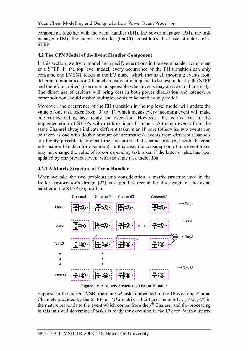
4.2.1 A Matrix Structure of Event Handler
When we take the two problems into consideration, a matrix structure used in the
Butler coprocessor’s design [22] is a good reference for the design of the event
handler in the STEP (Figure 11).
W
S&
W
S&
W
S&
W
S&
W
S&
W
S&
W
S&
W
S&
W
S&
W
S&
W
S&
W
S&
W
S&
W
S&
W
S&
W
S&
W
S&
W
S&
W
S&
W
S&
W
S&
W
S&
W
S&
W
S&
W
S&
W
S&
W
S&
W
S&
W
S&
W
S&
W
S&
W
S&
W
S&
W
S&
W
S&
W
S&
W
S&
W
S&
W
S&
W
S&
W
S&
W
S&
W
S&
W
S&
W
S&
W
S&
W
S&
W
S&
Task1
Task2
Task3
TaskM
Channel1 Channel2 Channel3 ChannelS
OR Rdy3
Rdy1
Rdy2
RdyM
Figure 11: A Matrix Structure of Event Handler
Suppose in the current VSB, there are M tasks embedded in the IP core and S input
Channels provided by the STEP, an M*S matrix is built and the unit Ui,j (i≤M, j≤S) in
the matrix responds to the event which comes from the jth Channel and the processing
in this unit will determine if task i is ready for execution in the IP core. With a matrix
Yuan Chen: Modelling and Design of a Low Power Event Processor
NCL-EECE-MSD-TR-2008-136, Newcastle University
structure, several events coming from a different Channel can be responded to in
parallel since the corresponding executions are carried out in different units.
If there is at least one Ui,j in the ith row of the matrix indicating the i
th task is ready for
execution, a ready signal (which is written as Rdy for short in Figure 11) becomes
valid. All ready tasks are called candidates. One and only one candidate can be
scheduled out and loaded to the IP core for execution each time, and the ready signal
of the corresponding task will be withdrawn afterwards so that the task cannot be a
candidate for next scheduling.
The structure within every Ui,j relies on the implementation of the VSB. When the
VSB is used for data processing, the execution of a task needs the combination of
both operation codes and the data for operation. An incoming event in this case
indicates the corresponding data is available, and the operation codes which are
embedded in the IP core will be ready for execution except when they are just under
processing, or they are forbidden to be executed by other tasks in case of suspension,
interruption or synchronization etc [22]. Therefore, two 1-bit variables wait and stim
(which are written as W and S for short in Figure 11) are used in every unit of the
matrix. The wait bit will be set when the operation codes of the corresponding task are
ready for execution, and it will be reset otherwise. Similarly, the stim bit will be set
when the event (mainly the corresponding data) is accessible and it will be reset
otherwise. The ready signal for task i becomes valid (and the task becomes a
scheduling candidate) only when at least one Ui,j unit of the matrix has both stim and
wait bits set.
The matrix structure will give high expandability to the STEP. When used in different
environment or to cooperate with another IP core, the parameters of the matrix M and
S may be changed accordingly. However, the Event Handler component can be easily
adjusted by adding/deleting several units in the matrix while the entire structure keeps
the same. As every unit in the matrix structure is identical, we only present the CPN
model of a unit in this section (Figure 12).
4.2.2 Colour Set Description
When the implementation of the modelled VSB is specified as data processing, the
colour of EVENT and TASK will be re-declared. In most cases, each task is given a
unique ID number which will be used for the IP core to find the start address of the
corresponding codes in its ROM memory if needed. Therefore, the colour TASK will
be declared as:
color TASK = int with 0 .. Max
where Max is a constant standing for the maximum ID number used in the current
VSB.
When data is transferred among different domains with different clock frequencies, an
Asynchronous Communication Mechanism (ACM) can serve as an efficient and safe
method used in many implementations and will be used in VSB design. Because the
CPN model of an ACM has been designed in [23], an abstract DATA colour is
declared as the colour string (as the set of all text strings) whose content shown as the
DATA token value will be used to describe the property of the corresponding data.
color DATA = string
Therefore the colour EVENT is re-declared as:
Yuan Chen: Modelling and Design of a Low Power Event Processor
NCL-EECE-MSD-TR-2008-136, Newcastle University
color EVENT = product TASK*DATA
It means an EVENT token is composed by a TASK token and a DATA token. The
TASK token indicates which operation will be used to process the data represented by
the DATA token. The colour BIT keeps the same declaration in this model (as well as
the rest models in this paper).
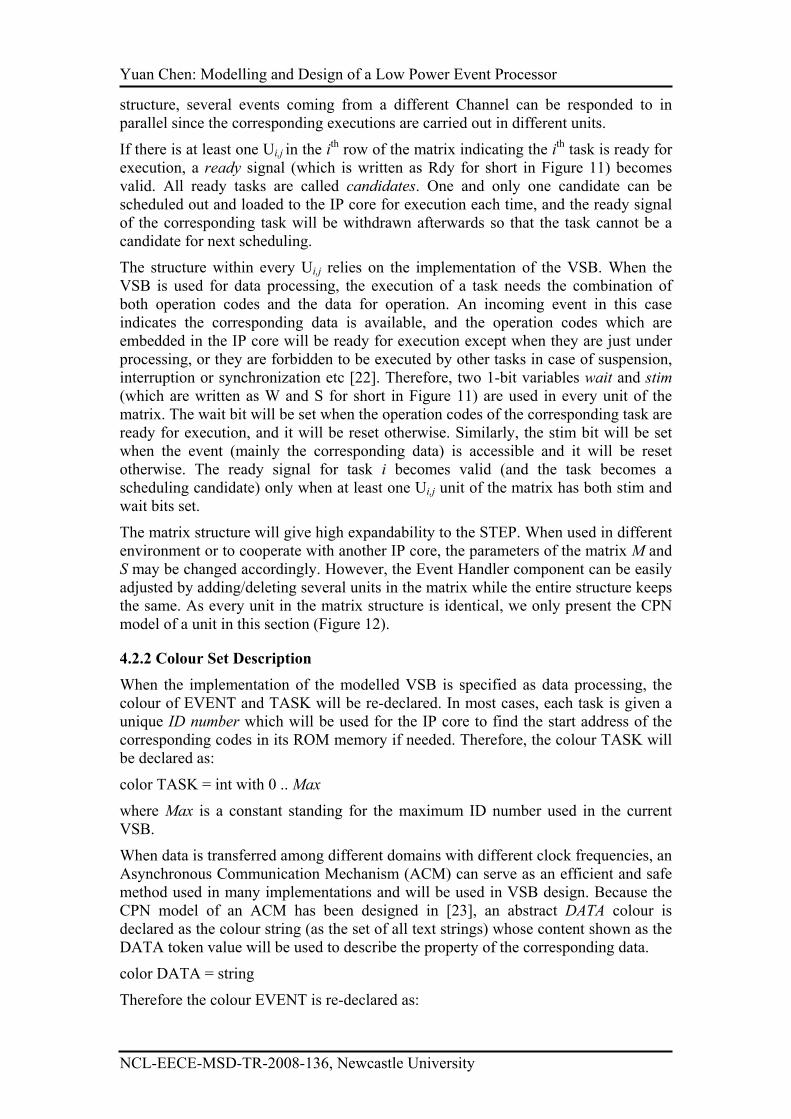
Figure 12: CPN Model of One Unit in the Event Handler
4.2.3 Model Description
In Figure 12, the place Channel is used to hold EVENT tokens coming from one
channel. A group of Channel places from all units of the Matrix is the extension of the
EQ place in the top level model. Any EVENT token in this place will enable the ACM
transition. This transition represents the data transfer carried out by the STEP when an
ACM is used. The detailed description of this transition can be found in [23]. The
occurrence of this transition will generate a TASK token to the ID place, which
indicates the completion of the data preparation for the task suggested by the token
value.
Constant ID1 in Figure 12 is declared as a constant integer which represents the ID
number of the task represented by the current unit. A guard [task=ID1] is attached in
the upper left side of the transition Sstim (means Set stim bit). A guard is a Boolean
expression and the corresponding transition is enabled only when the Boolean
expression is true. Therefore, the Sstim transition is only enabled by a TASK token
valued in ‘1’ (ID1 is currently declared as 1). The occurrence of the Sstim transition
will update the token value in the Stim place to ‘1’ which means the data for the
execution of task1 (taski is the short expression for the task whose ID number is i) is
ready for execution. With an initial ‘1’ token available in the wait place, the transition
Candidate is enabled and the occurrence of this transition will update the token in the
Rdy place to ‘1’ which means task1 becomes a candidate for scheduling. A group of
Rdy places from all units of the Matrix is the extension of the TQ place in the top
level model.
Yuan Chen: Modelling and Design of a Low Power Event Processor
NCL-EECE-MSD-TR-2008-136, Newcastle University
The token value in the place Ntask indicates which task is chosen to be loaded to the
IP core. Variable ntask is declared to represent the token value in the Ntask place.
When the token value in this place becomes ‘1’, the transition selected is enabled
because task1 will be loaded to the IP core for execution. The occurrence of this
transition will reset the value of tokens in both stim and wait places and the transition
Decand (means disabled candidate) is enabled in sequence. The occurrence of the
Decand transition will reset the token value in the Rdy place to ‘0’, which means
task1 will no longer be a candidate for scheduling and the corresponding ready signal
becomes invalid.
4.2.4 Environmental Set Description
Similarly in the top level model in Figure 7, environmental places/transitions are
highlighted by dark shade in the current model. The transition Schedule is used to
represent the scheduling processing in the STEP. This transition is enabled only when
the token in the Rdy place is ‘1’ because the scheduling result will influence the
current model only when task1 is a candidate task. No matter what scheduling policy
may be implemented in the STEP, how quickly task1 can be chosen for loading after
it becomes a candidate task is nondeterministic. Therefore, a CPN function New() is
declared as follows:
fun New()=discrete(1,5)
This function will use the random integer number generator discrete provided by CPN
Tools to generate a random integer number from 1 to 5. And the generated number
indicates the ID number of the new selected task. A guide [ntask<>ID1] (means ntask
is not equal to ID1) is attached to the Schedule transition to make sure that the
scheduling (as well as the execution of tasks in the IP core) is enabled until task1 is
chosen (after that the scheduling result will not influence the current model until the
token value in the Rdy place becomes ‘1’ again).
The execution of the selected transition will also generate two tokens, one for the new
place and the other for the new2 place. The cooperation of place new with transitions
env and env1 are used to simulate the stochastic generation of another event
corresponding to task1 from the same channel. The description of these places/
transitions can be referred to places/transitions with the same names in the top level
model. CPN function P1() (as well as P2() in the expression of arc directing from the
execution transition to the new2 place) shares the same form as the P() function in the
top level with different rate λ. The occurrence of the transition env1 represents the
incoming of another event (as well as the data) corresponding to task1 in the current
model.
Similarly, the cooperation of the place new2 with the transition execution is used to
simulate the execution of task1 in the IP core. When a ‘1’ token is generated in the
new2 place, it indicates the execution of task1 is complete so that the wait bit will be
set again accordingly by the occurrence of the Swait transition.
Because of the random token value given by functions P1() and P2(), either the
transition Sstim or Swait can be first enabled (or they are concurrently enabled),
which reflects the nondeterministic operations in the STEP. CPN simulation and state
space checking has been done to prove the correct design of the current model.
4.3 The CPN Model of the Power Manager Component
Yuan Chen: Modelling and Design of a Low Power Event Processor
NCL-EECE-MSD-TR-2008-136, Newcastle University
In this section, we try to model and specify executions in the power manager
component of a STEP where A&F policy is implemented. According to the previous
section, a group of ready signals indicates the status of tasks embedded in the IP core.
And the A&F policy can be realized by counting the number of valid ready signals so
as to decide whether task accumulation is enough or not.
When tasks in an IP core are assumed to be independent from each other, there is no
pattern that can be predicted when their corresponding ready signals become valid.
The STEP must be alert to any change in ready signals so as not to miss any new valid
ready signals. On the other side, a valid ready signal will only be withdrawn by the
reset in some stim & wait bits in the Event Handler. Since the PM part in the STEP
cannot disable any ready signals after accumulation counting, the PM needs to know
which ready signals have been used in the accumulation and which are not.
Furthermore, the Matrix structure used in the Event Handler enables responding to
events from different Channels in parallel, and therefore several ready signals can
become valid simultaneously. These signals need to be arbitrated before they are
counted and added to the accumulation result.
4.3.1 Model Description
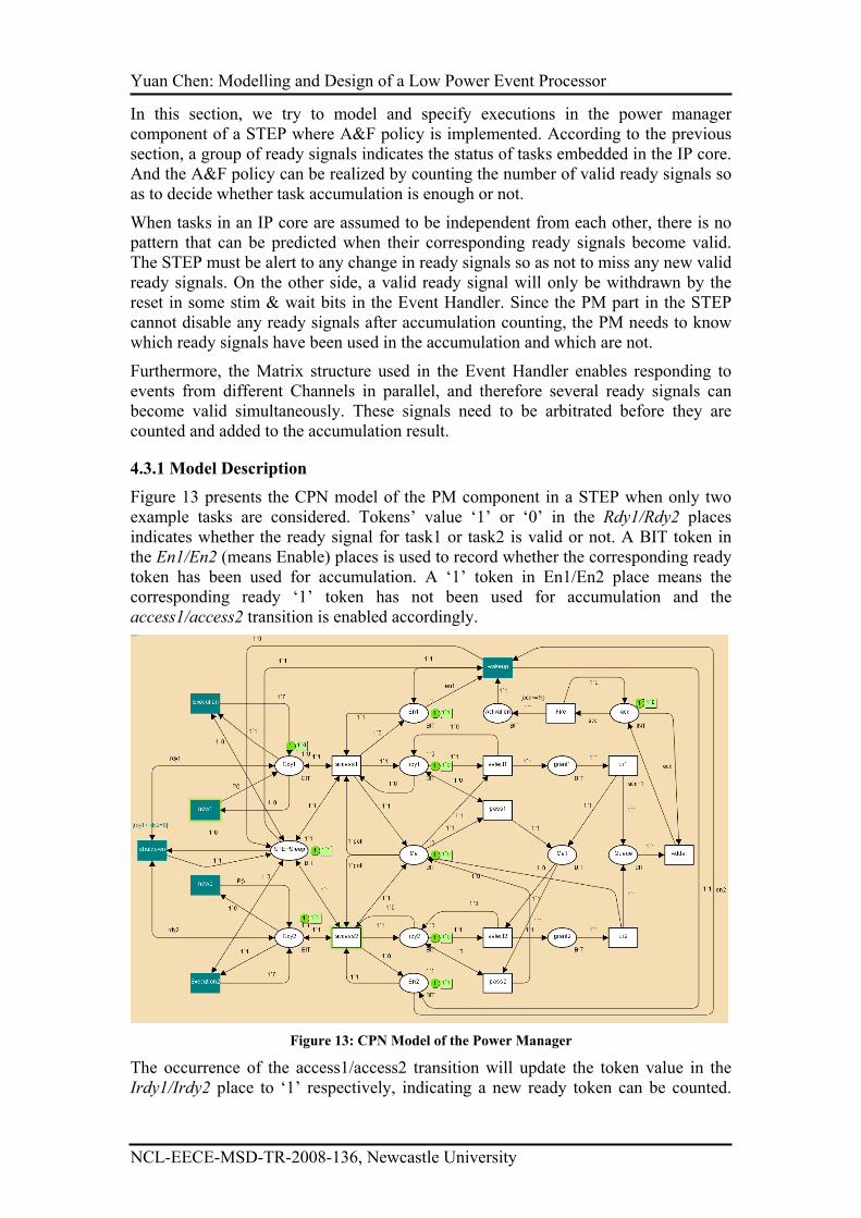
Figure 13 presents the CPN model of the PM component in a STEP when only two
example tasks are considered. Tokens’ value ‘1’ or ‘0’ in the Rdy1/Rdy2 places
indicates whether the ready signal for task1 or task2 is valid or not. A BIT token in
the En1/En2 (means Enable) places is used to record whether the corresponding ready
token has been used for accumulation. A ‘1’ token in En1/En2 place means the
corresponding ready ‘1’ token has not been used for accumulation and the
access1/access2 transition is enabled accordingly.
Figure 13: CPN Model of the Power Manager
The occurrence of the access1/access2 transition will update the token value in the
Irdy1/Irdy2 place to ‘1’ respectively, indicating a new ready token can be counted.
Yuan Chen: Modelling and Design of a Low Power Event Processor
NCL-EECE-MSD-TR-2008-136, Newcastle University
The occurrence of the access1/access2 transition will also toggle the token value in
En1/En2 place to ‘0’ so that the ‘1’ token in Rdy1/Rdy2 can only enable the
access1/access2 transition any more and duplicated counting is avoided in this model.
As demonstrated in the top level model, the PM only needs to work when the IP core
is inactive. Therefore, transitions access1/access2 can be enabled only when the token
value in the STEPSleep place is ‘1’. This place is related but not the same as the Sleep
place in the top level model, and their relationship will be explained in Section 4.4.2.
Because only one accumulation value is kept in the PM, all valid ready signals can
only be added to the accumulation value in sequence. Therefore arbiters are
indispensible in the current model. We choose the ring based arbiter introduced in
[24] for the arbiter design in the Power Manager. In this case, a valid ready signal can
be added to the accumulation only when some polling signal arrives. And an arbiter is
used for the arbitration between a valid ready signal and the polling signal. It is only
when a ready signal is granted by the arbiter that it can be added to the accumulation
result.
In the current CPN model, the polling token is held in the Me/Me1 places and when at
least one access transition occurs, the token in the Me place becomes ‘1’ to enable the
polling accumulation. The pair of select1 and pass1 transitions indicates the operation
of polling accumulation of the ready signal for task1. If the token value in Irdy1 is ‘1’,
the availability of the polling token in the Me place will enable the transition select1.
The occurrence of the transition will first grant the ready token for accumulation, and
then pass the polling token to the Me1 place. If the token value in Irdy2 is ‘0’, the
transition pass1 will be enabled accordingly and pass the polling token directly to the
Me1 place. The occurrence of select2/pass2 transition is carried out in the similar way
and it will return the polling token to the Me place. For power saving reason, the
polling will be ended after the occurrence of select2/pass2 transition since the polling
token value is reset to ‘0’, and it will begin next time when at least one
access1/access2 transition occurs.
The or1/or2 transitions represent a logical OR gate, and the execution of one or1/or2
transition will add one token to the Queue place and move the polling token to the
Me/Me1 place and let the token polling continue. The colour in the place acc is set to
INT because the integer value of the token held in this place represents the
accumulation result. As soon as one token is available in the Queue place, the Adder
transition is enabled and the execution of this transition will increase the accumulation
by 1. One guard [acc>=N] is attached to the Fire transition to make sure one token
will be added to the Activation place only when the token value in the acc place is
greater than the accumulation limit N (N is set to 2 in the current model). The
occurrence of the Fire transition will reset the token value in the acc place to ‘0’ to
prepare for the next accumulation procedure.
4.3.2 Environmental Set Description
The environmental transition Wakeup represents the wakeup processing in the IP core
and its occurrence will set the token in the STEPSleep place to ‘0’ and all transitions
in the current model are disabled afterwards. The occurrence of this transition will
also set the tokens in both En1 and En2 places to ‘1’ so that new valid ready tokens
can access the current model when the IP core becomes inactive again.
In the left side of Figure 13, environmental transitions Execution1 and Execution2
represent the executions of task1 and task2 in the IP core respectively. These two

Yuan Chen: Modelling and Design of a Low Power Event Processor
NCL-EECE-MSD-TR-2008-136, Newcastle University
transitions can be enabled concurrently and the random occurrence of these transitions
represents the different scheduling result generated by the STEP. The occurrence of
each Execution transition will reset the token value in the corresponding Rdy place.
Assuming only two tasks are embedded in the IP core, the shutdown transition is
enabled when both tokens in the Rdyi place are ‘0’.
Environmental transitions new1 and new2 are used to change the token values in their
corresponding Rdy1/Rdy2 places. The occurrences of these transitions reflect the
generation of new events in the environment and function P() (which is also used in
the top level model) is used to make the generation of tokens in Rdyi place
stochastically. All these environmental transitions/places will generate all possible
combination of input tokens to and consume output tokens from the current system.
The correctness of the current model has been verified by state space checking.
4.4 The CPN Model of the Task Manager Component
In this section, we try to model and specify executions in the task manager component
of a STEP where task scheduling is provided.
4.4.1 Priority Based Round Robin Scheduling Priority
Although many different scheduling priorities have been used in various systems, we
prefer to use a priority based round robin policy (Figure 14) in our task manager
design.
Candidate
Candidate
Candidate
Candidate
Candidate
Candidate
Candidate
Candidate
Candidate
Candidate
Candidate
Candidate
Candidate
Candidate
Candidate
Candidate
Figure 14: Priority Based Round Robin Policy
Arrows in the left of Figure 14 keep a list of all tasks in the IP core sorted by their
priorities. A dotted arrow represents an invalid scheduling candidate (the
corresponding task is not ready for execution) and a solid arrow indicates a valid
candidate. A new scheduling will always start from the highest priority group and
towards the lowest priority group. For tasks in the same priority group, the scheduler
will use round robin policy to choose a new task so as to give all tasks in the same
group fair opportunity to be executed in the IP core.
In each priority group, the task loaded to the IP core most recently is marked as a last
task. In Figure 14, the last task in every priority group is pointed by the Begin arrow.
A new polling scheduling starts from the last task in the highest priority group and
Yuan Chen: Modelling and Design of a Low Power Event Processor
NCL-EECE-MSD-TR-2008-136, Newcastle University
checks the validation of each task in turn. The scheduling ends when the first valid
task is found. If no valid candidate can be found in this group, the scheduling point
will jump to the last task in the second highest priority group to carry out the similar
exploration. When no valid task can be found even in the lowest priority group, it
means no task is ready for execution, and a particular ID number (for example 0 or
255) will be fetched to the IP core.
4.4.2 The CPN Model for Task Manager
Figure 15 gives one example model of the Task Manager in the STEP and its test
environment when only two tasks (and one priority group) is concerned in the
scheduling.
The environmental place within the dotted circle is named LoadEn whose token ‘1’
represents the task loading request from the IP core. A ‘1’ token in the LoadEn place
will enable the Load transition in the right side of the figure and the occurrence of the
transition indicates the task loading execution in the IP core. One token whose value
is the ID number of the new task will be added to the Ltask (means Loaded task) place
in consequence.
Tokens in the Rdy1/Rdy2 places indicate whether task1/task2 is a valid candidate task
or not. As external events may come to the current VSB at any time, the two tokens in
the Rdy1 and Rdy2 places may become ‘1’ simultaneously when the Load transition
is enabled. In this case, new scheduling execution and task loading execution are
carried out simultaneously. Suppose the new scheduling will update the token value in
the Ntask place from ‘1’ to ‘2’, whether task1 or task2 will be loaded to the IP core
depends on whether the scheduling transitions or the loading transition will occur
first. The uncertainty in task loading will confuse the IP core and may cause serious
consequence. A safer design will enable scheduling only when no load request is
given. In Figure 15, transitions Access1 and Access2 can be enabled only when the
token value in the LoadEn place is ‘0’. Therefore, when the token in the LoadEn place
becomes ‘1’, no further token change in Rdy1/Rdy2 place can influence the token
value in the LTask place. As task scheduling is of no use when the IP core is in its off
mode, another enabling precondition of transitions access1 and access2 is the
existence of ‘0’ token in the STEPSleep place.
The tokens held in places Irdy1 and Irdy2 indicate the status of ready signals for the
usage of scheduling. Variables irdy1, irdy2, rdy1 and rdy2 are used to indicate the
token value in the place with the same name (But capital first character) respectively.
With the guard [irdy1<>rdy1] and [irdy2<>rdy2] in the access1/access2 transitions,
scheduling will only begin when some changes happen to the ready signals. The
occurrence of these transitions will update the token value in the Me place to ‘1’.
Places and transitions within the dotted rectangle represent the scheduling executions
of two tasks in a priority based round robin policy and the detailed explain can be
found in [27].
According to the model, when more than one ready token is toggled concurrently, one
Assessi (i=1,2) transition and some scheduling transition within the dotted rectangle
may be enabled concurrently. The different occurrence sequences of these transitions
reflect the competition between the validation of a ready signal and the arrival of the
round robin polling signal. However, given no valid LoadEn signal is generated from
the IP core, different occurrence sequences of these transitions will achieve the same
scheduling result.
Yuan Chen: Modelling and Design of a Low Power Event Processor
NCL-EECE-MSD-TR-2008-136, Newcastle University
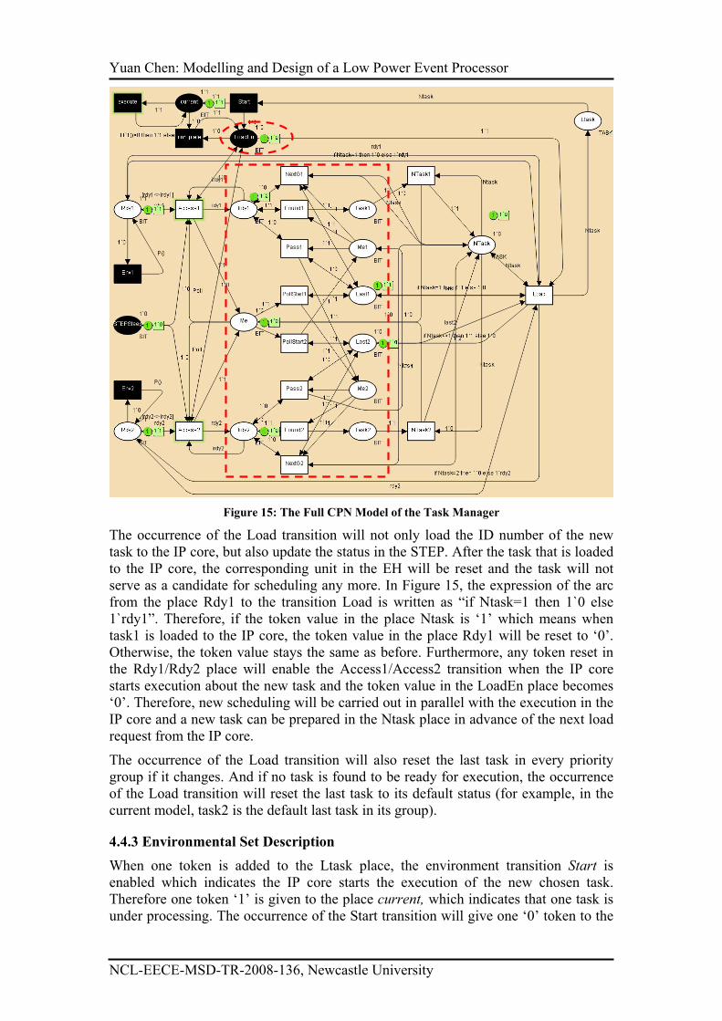
Figure 15: The Full CPN Model of the Task Manager
The occurrence of the Load transition will not only load the ID number of the new
task to the IP core, but also update the status in the STEP. After the task that is loaded
to the IP core, the corresponding unit in the EH will be reset and the task will not
serve as a candidate for scheduling any more. In Figure 15, the expression of the arc
from the place Rdy1 to the transition Load is written as “if Ntask=1 then 1`0 else
1`rdy1”. Therefore, if the token value in the place Ntask is ‘1’ which means when
task1 is loaded to the IP core, the token value in the place Rdy1 will be reset to ‘0’.
Otherwise, the token value stays the same as before. Furthermore, any token reset in
the Rdy1/Rdy2 place will enable the Access1/Access2 transition when the IP core
starts execution about the new task and the token value in the LoadEn place becomes
‘0’. Therefore, new scheduling will be carried out in parallel with the execution in the
IP core and a new task can be prepared in the Ntask place in advance of the next load
request from the IP core.
The occurrence of the Load transition will also reset the last task in every priority
group if it changes. And if no task is found to be ready for execution, the occurrence
of the Load transition will reset the last task to its default status (for example, in the
current model, task2 is the default last task in its group).
4.4.3 Environmental Set Description
When one token is added to the Ltask place, the environment transition Start is
enabled which indicates the IP core starts the execution of the new chosen task.
Therefore one token ‘1’ is given to the place current, which indicates that one task is
under processing. The occurrence of the Start transition will give one ‘0’ token to the

Yuan Chen: Modelling and Design of a Low Power Event Processor
NCL-EECE-MSD-TR-2008-136, Newcastle University
LoadEn place, which means the task loading procedure is completed. One function
P1() (which is the same as the P1() function in the EH unit model in Figure 12) is
used in the arc expression from the execution transition to the current place. This
function is used to simulate the stochastic processing behaviour in the IP core. When
the token value in the current place becomes ‘0’, the current task’s execution is
completed. And the token value in the LoadEn place will be updated to ‘1’ and new
tasks will be loaded afterwards. If the taken value in the Ltask place is ‘0’ which
means no more valid task has been loaded to the IP core, the Start transition can be
seen to indicate the shutdown operation in the IP core and the execute transition can
be seen to indicate task accumulation procedure. Similarly, the complete transition
indicates the activation of the IP core in this case.
The environmental transition Env1/Env2 uses the function P() (which has been
introduced in the top level model) to simulate the generation of new event which will
in turn validate the corresponding ready signals again. All these environmental
transitions/places will generate all possible combinations of input tokens to and
consume output tokens from the current system. State space has been done to prove
the correctness of the current model.
4.5 The CPN Model of the Output Controller and Interface Components
When the wakeup and shutdown executions in an IP core are not taken as
instantaneous, it is highly possible that some events come during the same time. As
indicated in Section 4.1.6, executions in the STEP about these events may interrupt
the mode switching transitions in an IP core so as to bring serious consequences. The
interface design in this section is to avoid possible hazard brought by STEP
executions.
As indicated in the top level model, the output controller will generate a new event
when the execution of the current task is completed. If the new task stimulated by the
event generated from the output controller locates in the same VSB, the new task can
become ready for execution much faster than the case when the new task is located in
the other VSB. It is because both asynchronous/synchronous transform and data
transfer between two VSBs are omitted. The CPN Model in this section tries to
specify this difference.
Figure 16 presents the CPN model of the Interface and Output Control part in the
STEP where only two example tasks (task1 and task2) are concerned. The
declarations of the four token colours involved in the figure, BIT, EVENT, TASK and
DATA, are the same as those given in the EH CPN model in Section 4.2.
The relationship among Fire and wakeup transition as well as the Activation and
STEPSleep places have been introduced in the PM in Section 4.3 (the accumulation
limit is set to 1 to simplify the current model). The token in the STEPSleep place
indicates the command given by the PM while that in the Sleep place indicates the
mode of the IP core. Transitions Waking and Shutting represent the wakeup and
shutdown executions in the IP core respectively. A ‘0’ token in the STEPSleep place
will enable the Waking transition and the latter’s occurrence will update the token in
the Sleep place to ‘0’, which indicates the completion of the wakeup execution in the
IP core. In Section 4.3 and 4.4, the token in the STEPSleep place instead of that in the
Sleep place is used to enable/disable the executions in the PM and TM components.
Therefore, the PM execution can be terminated and the TM execution can start as
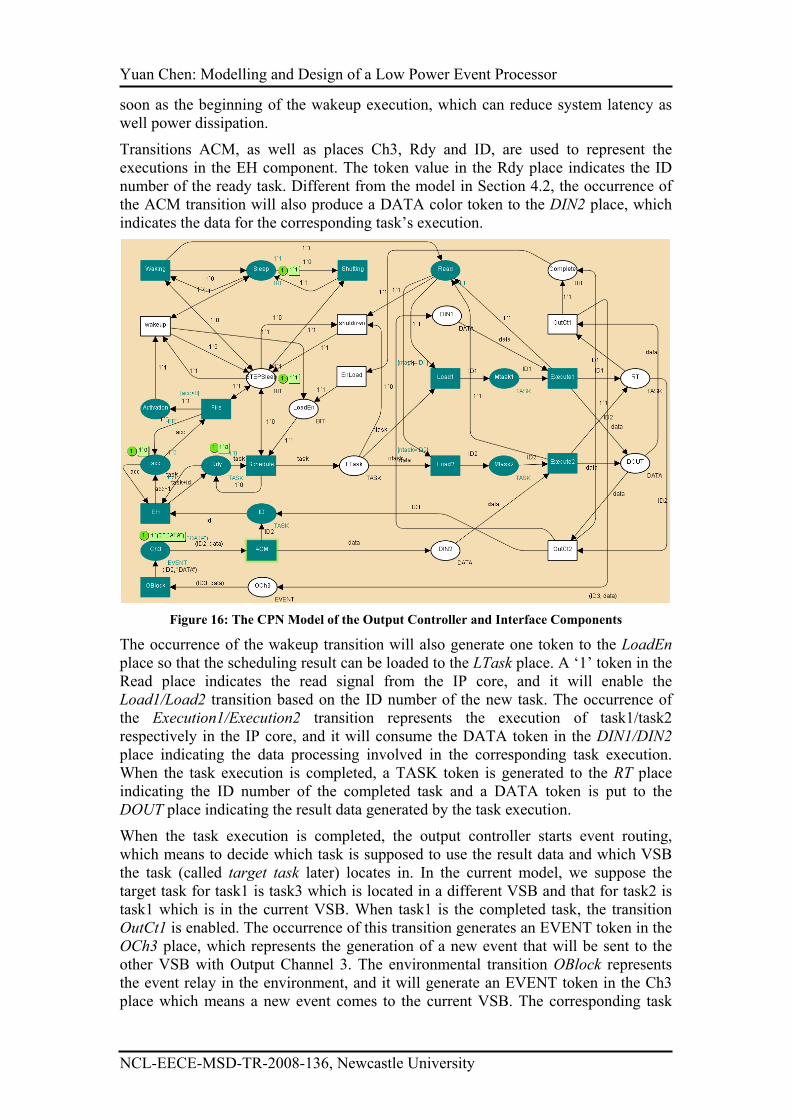
Yuan Chen: Modelling and Design of a Low Power Event Processor
NCL-EECE-MSD-TR-2008-136, Newcastle University
soon as the beginning of the wakeup execution, which can reduce system latency as
well power dissipation.
Transitions ACM, as well as places Ch3, Rdy and ID, are used to represent the
executions in the EH component. The token value in the Rdy place indicates the ID
number of the ready task. Different from the model in Section 4.2, the occurrence of
the ACM transition will also produce a DATA color token to the DIN2 place, which
indicates the data for the corresponding task’s execution.
Figure 16: The CPN Model of the Output Controller and Interface Components
The occurrence of the wakeup transition will also generate one token to the LoadEn
place so that the scheduling result can be loaded to the LTask place. A ‘1’ token in the
Read place indicates the read signal from the IP core, and it will enable the
Load1/Load2 transition based on the ID number of the new task. The occurrence of
the Execution1/Execution2 transition represents the execution of task1/task2
respectively in the IP core, and it will consume the DATA token in the DIN1/DIN2
place indicating the data processing involved in the corresponding task execution.
When the task execution is completed, a TASK token is generated to the RT place
indicating the ID number of the completed task and a DATA token is put to the
DOUT place indicating the result data generated by the task execution.
When the task execution is completed, the output controller starts event routing,
which means to decide which task is supposed to use the result data and which VSB
the task (called target task later) locates in. In the current model, we suppose the
target task for task1 is task3 which is located in a different VSB and that for task2 is
task1 which is in the current VSB. When task1 is the completed task, the transition
OutCt1 is enabled. The occurrence of this transition generates an EVENT token in the
OCh3 place, which represents the generation of a new event that will be sent to the
other VSB with Output Channel 3. The environmental transition OBlock represents
the event relay in the environment, and it will generate an EVENT token in the Ch3
place which means a new event comes to the current VSB. The corresponding task
Yuan Chen: Modelling and Design of a Low Power Event Processor
NCL-EECE-MSD-TR-2008-136, Newcastle University
can become ready only after the completion of data transfer/transform represented by
the occurrence of the ACM transition.
On the other hand when task2 is the completed task, the transition OutCt2 is enabled.
Its occurrence simply move the DATA token to the DIN1 place because it represents
simple data transfer within the same time domain. Therefore task1, as the target task
of task2, can become ready much faster than the previous case. The occurrence of
OutCt1/OutCt2 transition will also add one token to the Complete place, which
indicates the completion of output control. A BIT token is added to the LoadEn place
in sequence to require the new task from the TM component. If the value of the token
moved to the Ltask place is ‘0’, it indicates no active task can be found. In this case,
the shutdown transition is enabled whose occurrence will toggle the token value in the
STEPSleep to ‘1’. This token value change will enable the shutting transition and the
token value in the Sleep place will be changed to ‘1’ after the latter’s occurrence.
In Section 4.1.6, we present the hazard brought by concurrent execution of the event
handling in the STEP and the shutdown processing in the IP core. This hazard is
avoided by the design in the current model. When the shutdown processing is carried
out in the IP core, the token value in the STEPSleep place is ‘1’ and that in the Sleep
place is ‘0’. Suppose there are enough events come during this period and the Fire
transition occurs to generate a ‘1’ token in the Activation place. However, the wakeup
transition cannot be enabled because it requires a ‘1’ token in the Sleep place. When
the wakeup transition is disabled, no token will be sent to the LoadEn place.
Therefore, no new task will be loaded to the IP core so as to interrupt the shutdown
processing.
From Section 4.2 to Section 4.5, we present four CPN models to extend the top level
CPN model of a VSB. Each CPN model specifies the design in one part of the STEP.
The concurrent executions in different components of the VSB are highlighted by the
simulation tool provided by CPN Tools. The state space tool is used to check the
correctness of the design. In next section, we try to implement the VSB design to
build one example SoC where some realistic tasks are carried out.
5. THE CONSTRUCTION OF SOC WITH VSBS
In the previous section, all important executions in a STEP have been modelled and
specified in CPN models. However, the executions in the corresponding IP core are
abstracted to only two transitions (the Loadi and Executioni (i=1,2) transitions in
Section 4.5). It is because our main concern is about the design of a STEP which can
cooperate with different kinds of IP cores. Although the execution detail in an IP core
can be abstracted away because it has little influence on the VSB design, it has great
impact on the VSB performance. The analysis of both power and latency performance
in a VSB can only be carried out when the IP core is specified.
Furthermore, our modelling and analysis work from Sections 2 to 4 assumes the
arrival of events follows exponential distribution. This assumption cannot be satisfied
in all implementations. Therefore, we have to explore the performance of our VSB
with A&F control when event arrival follows non-exponential distribution.
Therefore, an example implementation of VSB named as “ball game” is designed
where some example tasks are controlled by VSBs to perform data processing in a
SOC content.
5.1 Implementation Specification
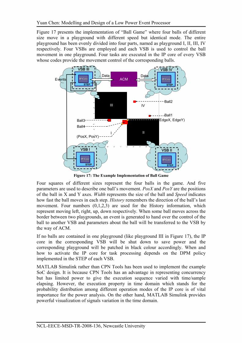
Yuan Chen: Modelling and Design of a Low Power Event Processor
NCL-EECE-MSD-TR-2008-136, Newcastle University
Figure 17 presents the implementation of “Ball Game” where four balls of different
size move in a playground with different speed but identical mode. The entire
playground has been evenly divided into four parts, named as playground I, II, III, IV
respectively. Four VSBs are employed and each VSB is used to control the ball
movement in one playground. Four tasks are executed in the IP core of every VSB
whose codes provide the movement control of the corresponding balls.
Ball3
Ball4
Ball2
Ball1
(PosX, PosY)
(EdgeX, EdgeY)
I II
III IV
IP CoreIP CoreIP Core
STEP
VSB III
IP CoreIP CoreIP Core
STEP
VSB III
IP CoreIP CoreIP Core
STEP
VSB I
IP CoreIP CoreIP Core
STEP
VSB I
IP CoreIP CoreIP Core
STEP
VSB IV
IP CoreIP CoreIP Core
STEP
VSB IV
IP CoreIP CoreIP Core
STEP
VSB II
IP CoreIP CoreIP Core
STEP
VSB II
ACMData Data
Events
Figure 17: The Example Implementation of Ball Game
Four squares of different sizes represent the four balls in the game. And five
parameters are used to describe one ball’s movement. PosX and PosY are the positions
of the ball in X and Y axes. Width represents the size of the ball and Speed indicates
how fast the ball moves in each step. History remembers the direction of the ball’s last
movement. Four numbers (0,1,2,3) are used for the History information, which
represent moving left, right, up, down respectively. When some ball moves across the
border between two playgrounds, an event is generated to hand over the control of the
ball to another VSB and parameters about the ball will be transferred to the VSB by
the way of ACM.
If no balls are contained in one playground (like playground III in Figure 17), the IP
core in the corresponding VSB will be shut down to save power and the
corresponding playground will be patched in black colour accordingly. When and
how to activate the IP core for task processing depends on the DPM policy
implemented in the STEP of each VSB.
MATLAB Simulink rather than CPN Tools has been used to implement the example
SoC design. It is because CPN Tools has an advantage in representing concurrency
but has limited power to give the execution sequence varied with time/sample
elapsing. However, the execution property in time domain which stands for the
probability distribution among different operation modes of the IP core is of vital
importance for the power analysis. On the other hand, MATLAB Simulink provides
powerful visualization of signals variation in the time domain.
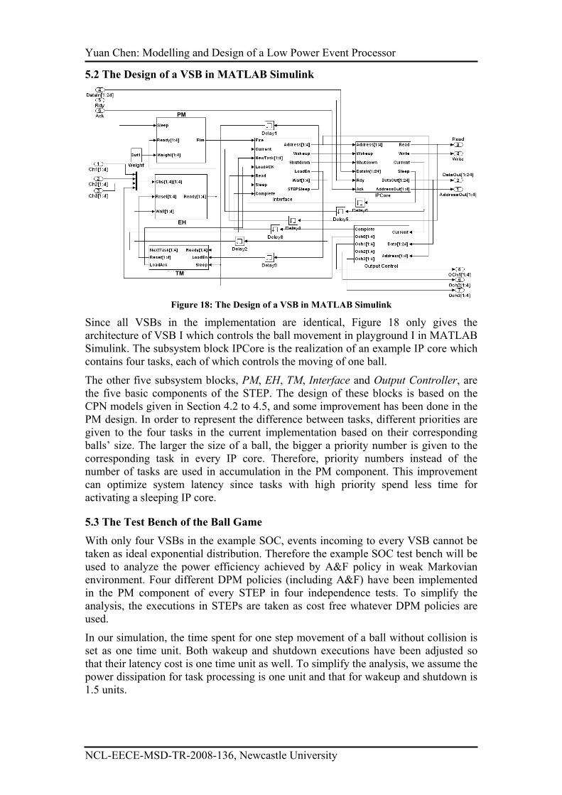
Yuan Chen: Modelling and Design of a Low Power Event Processor
NCL-EECE-MSD-TR-2008-136, Newcastle University
5.2 The Design of a VSB in MATLAB Simulink
PM
EH
TM
Figure 18: The Design of a VSB in MATLAB Simulink
Since all VSBs in the implementation are identical, Figure 18 only gives the
architecture of VSB I which controls the ball movement in playground I in MATLAB
Simulink. The subsystem block IPCore is the realization of an example IP core which
contains four tasks, each of which controls the moving of one ball.
The other five subsystem blocks, PM, EH, TM, Interface and Output Controller, are
the five basic components of the STEP. The design of these blocks is based on the
CPN models given in Section 4.2 to 4.5, and some improvement has been done in the
PM design. In order to represent the difference between tasks, different priorities are
given to the four tasks in the current implementation based on their corresponding
balls’ size. The larger the size of a ball, the bigger a priority number is given to the
corresponding task in every IP core. Therefore, priority numbers instead of the
number of tasks are used in accumulation in the PM component. This improvement
can optimize system latency since tasks with high priority spend less time for
activating a sleeping IP core.
5.3 The Test Bench of the Ball Game
With only four VSBs in the example SOC, events incoming to every VSB cannot be
taken as ideal exponential distribution. Therefore the example SOC test bench will be
used to analyze the power efficiency achieved by A&F policy in weak Markovian
environment. Four different DPM policies (including A&F) have been implemented
in the PM component of every STEP in four independence tests. To simplify the
analysis, the executions in STEPs are taken as cost free whatever DPM policies are
used.
In our simulation, the time spent for one step movement of a ball without collision is
set as one time unit. Both wakeup and shutdown executions have been adjusted so
that their latency cost is one time unit as well. To simplify the analysis, we assume the
power dissipation for task processing is one unit and that for wakeup and shutdown is
1.5 units.
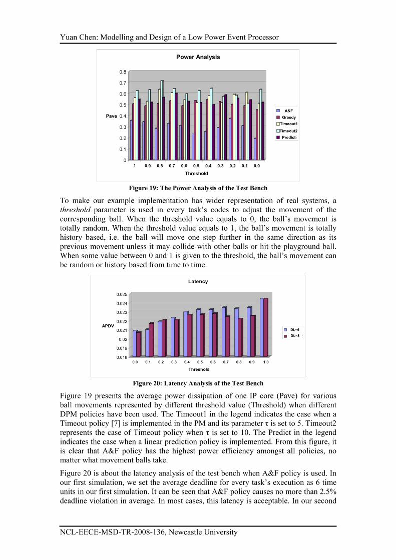
Yuan Chen: Modelling and Design of a Low Power Event Processor
NCL-EECE-MSD-TR-2008-136, Newcastle University
0
0.1
0.2
0.3
0.4
0.5
0.6
0.7
0.8
Pave
1 2 3 4 5 6 7 8 9 10 11
Threshold
Power Analysis
Series1
Series2
Series3
Series4
Series5
A&F
Greedy
Timeout1
Timeout2
Predict
0.9 0.8 0.7 0.6 0.5 0.4 0.3 0.2 0.1 0.0
Figure 19: The Power Analysis of the Test Bench
To make our example implementation has wider representation of real systems, a
threshold parameter is used in every task’s codes to adjust the movement of the
corresponding ball. When the threshold value equals to 0, the ball’s movement is
totally random. When the threshold value equals to 1, the ball’s movement is totally
history based, i.e. the ball will move one step further in the same direction as its
previous movement unless it may collide with other balls or hit the playground ball.
When some value between 0 and 1 is given to the threshold, the ball’s movement can
be random or history based from time to time.
0.018
0.019
0.02
0.021
0.022
0.023
0.024
0.025
APDV
1 2 3 4 5 6 7 8 9 10 11
Threshold
Latency
Series1
Series2
0.0 0.1 0.2 0.3 0.4 0.5 0.6 0.7 0.8 0.9 1.0
DL=6
DL=8
Figure 20: Latency Analysis of the Test Bench
Figure 19 presents the average power dissipation of one IP core (Pave) for various
ball movements represented by different threshold value (Threshold) when different
DPM policies have been used. The Timeout1 in the legend indicates the case when a
Timeout policy [7] is implemented in the PM and its parameter τ is set to 5. Timeout2
represents the case of Timeout policy when τ is set to 10. The Predict in the legend
indicates the case when a linear prediction policy is implemented. From this figure, it
is clear that A&F policy has the highest power efficiency amongst all policies, no
matter what movement balls take.
Figure 20 is about the latency analysis of the test bench when A&F policy is used. In
our first simulation, we set the average deadline for every task’s execution as 6 time
units in our first simulation. It can be seen that A&F policy causes no more than 2.5%
deadline violation in average. In most cases, this latency is acceptable. In our second
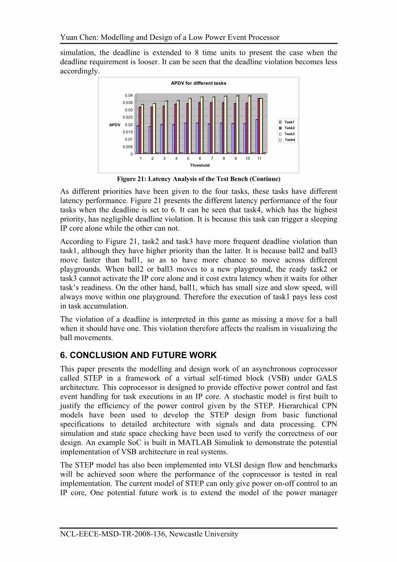
Yuan Chen: Modelling and Design of a Low Power Event Processor
NCL-EECE-MSD-TR-2008-136, Newcastle University
simulation, the deadline is extended to 8 time units to present the case when the
deadline requirement is looser. It can be seen that the deadline violation becomes less
accordingly.
0
0.005
0.01
0.015
0.02
0.025
0.03
0.035
0.04
APDV
1 2 3 4 5 6 7 8 9 10 11
Threshold
APDV for different tasks
Series1
Series2
Series3
Series4
Task1
Task2
Task3
Task4
Figure 21: Latency Analysis of the Test Bench (Continue)
As different priorities have been given to the four tasks, these tasks have different
latency performance. Figure 21 presents the different latency performance of the four
tasks when the deadline is set to 6. It can be seen that task4, which has the highest
priority, has negligible deadline violation. It is because this task can trigger a sleeping
IP core alone while the other can not.
According to Figure 21, task2 and task3 have more frequent deadline violation than
task1, although they have higher priority than the latter. It is because ball2 and ball3
move faster than ball1, so as to have more chance to move across different
playgrounds. When ball2 or ball3 moves to a new playground, the ready task2 or
task3 cannot activate the IP core alone and it cost extra latency when it waits for other
task’s readiness. On the other hand, ball1, which has small size and slow speed, will
always move within one playground. Therefore the execution of task1 pays less cost
in task accumulation.
The violation of a deadline is interpreted in this game as missing a move for a ball
when it should have one. This violation therefore affects the realism in visualizing the
ball movements.
6. CONCLUSION AND FUTURE WORK
This paper presents the modelling and design work of an asynchronous coprocessor
called STEP in a framework of a virtual self-timed block (VSB) under GALS
architecture. This coprocessor is designed to provide effective power control and fast
event handling for task executions in an IP core. A stochastic model is first built to
justify the efficiency of the power control given by the STEP. Hierarchical CPN
models have been used to develop the STEP design from basic functional
specifications to detailed architecture with signals and data processing. CPN
simulation and state space checking have been used to verify the correctness of our
design. An example SoC is built in MATLAB Simulink to demonstrate the potential
implementation of VSB architecture in real systems.
The STEP model has also been implemented into VLSI design flow and benchmarks
will be achieved soon where the performance of the coprocessor is tested in real
implementation. The current model of STEP can only give power on-off control to an
IP core, One potential future work is to extend the model of the power manager
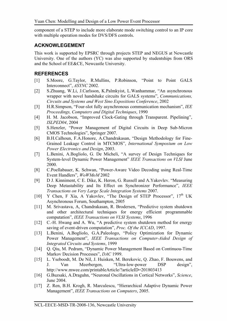
Yuan Chen: Modelling and Design of a Low Power Event Processor
NCL-EECE-MSD-TR-2008-136, Newcastle University
component of a STEP to include more elaborate mode switching control to an IP core
with multiple operation modes for DVS/DFS controls.
ACKNOWLEGEMENT
This work is supported by EPSRC through projects STEP and NEGUS at Newcastle
University. One of the authors (YC) was also supported by studentships from ORS
and the School of EE&CE, Newcastle University.
REFERENCES
[1] S.Moore, G.Taylor, R.Mullins, P.Robinson, “Point to Point GALS
Interconnect”, ASYNC 2002.
[2] S.Zhuang, W.Li, J.Carlsson, K.Palmkyist, L.Wanhammar, “An asynchronous
wrapper with novel handshake circuits for GALS systems”, Communications,
Circuits and Systems and West Sino Expositions Conference, 2002
[3] H.R.Simpson, “Four-slot fully asynchronous communication mechanism”, IEE
Proceedings, Computers and Digital Techniques, 1990
[4] H. M. Jacobson, “Improved Clock-Gating through Transparent. Pipelining”,
ISLPED04, 2004
[5] S.Henzler, “Power Management of Digital Circuits in Deep Sub-Micron
CMOS Technologies”, Springer 2007.
[6] B.H.Calhoun, F.A.Honore, A.Chandrakasan, “Design Methodology for Fine-
Grained Leakage Control in MTCMOS”, International Symposium on Low
Power Electronics and Design, 2003.
[7] L.Benini, A.Bogliolo, G. De Micheli, “A survey of Design Techniques for
System-level Dynamic Power Management” IEEE Transactions on VLSI June
2000.
[8] C.Poellabauer, K. Schwan, “Power-Aware Video Decoding using Real-Time
Event Handlers”, WoWMoM 2002
[9] D J. Kinniment, C E. Dike, K. Heron, G. Russell and A.Yakovlev. “Measuring
Deep Metastability and Its Effect on Synchronizer Performance”, IEEE
Transactions on Very Large Scale Integration Systems 2007.
[10] Y Chen, F Xia, A Yakovlev, “The Design of STEP Processor”, 17th UK
Asynchronous Forum, Southampton, 2005
[11] M. Srivastava, A, Chandrakasan, R. Brodersen, “Predictive system shutdown
and other architectural techniques for energy efficient programmable
computation”, IEEE Transactions on VLSI Systems, 1996
[12] C.-H. Hwang and A. Wu, “A predictive system shutdown method for energy
saving of event-driven computation”, Proc. Of the ICCAD, 1997.
[13] L.Benini, A.Bogliolo, G.A.Paleologo, “Policy Optimization for Dynamic
Power Management”, IEEE Transactions on Computer-Aided Design of
Integrated Circuits and Systems, 1999
[14] Q. Qiu, M. Pedram, “Dynamic Power Management Based on Continuou-Time
Markov Decision Processes”, DAC 1999.
[15] L. Yseboodt, M. De Nil, J. Huisken, M. Berekovic, Q. Zhao, F. Bouwens, and
J. Van Meerbergen, “Ultra-low-power DSP design”,
http://www.mwee.com/printableArticle/?articleID=201803413
[16] G.Buzsaki, A.Draguhn, “Neuronal Oscillations in Cortical Networks”, Science,
June 2004.
[17] Z. Ren, B.H. Krogh, R. Marculescu, “Hierarchical Adaptive Dynamic Power
Management”, IEEE Transactions on Computers, 2005.

Yuan Chen: Modelling and Design of a Low Power Event Processor
NCL-EECE-MSD-TR-2008-136, Newcastle University
[18] Y.Lu, E.Chung, T. Simunic, L. Benini, G. De Micheli “Quantitative
Comparison of Power Management Algorithms”, DATE 2000.
[19] Y Chen, F Xia, D Shang, A Yakolev “Stochastic Modeling Of Dynamic Power
Management Policies And Analysis Of Their Power-Latency Tradeoffs”, 4th
UKEF, Southampton, 2008
[20] Yuan Chen, Fei Xia, Delong Shang and Alex Yakolev “Stochastic Modeling
Of Dynamic Power Management Policies And Analysis Of Their Power-
Latency Tradeoffs”, 4th UKEF, Southampton, 2008
[21] CPN Tools, http://wiki.daimi.au.dk/cpntools/cpntools.wiki
[22] E.Campbell, H.Simpson, “Patent – Integrated circuits for multitasking support
in single or multiple processor networks”, World Intellectual Property
Organisation WO 97/22926, June 1997
[23] K. Gorgonio, F. Xia, “Modeling and Verifying Asynchronous Communication
Mechanisms using Coloured Petri Nets”, Technical Report, NCL-EECE-MSD-
TR-2008-127, School of EECE, Newcastle University, March 2008
[24] D.J.Kinniment, “Synchronization and Arbitration in Digital Systems”, John
Wiley & Sons, Ltd, 2007.
[25] J. Cortadella, K. Gorgonio, F. Xia, A. Yakovlev, “Automating Synthesis of
Asynchronous Communication Mechanisms”. ACSD 2005
[26] K.Jensen, L.M.Kristensen, L.Wells, “Coloured Petri Nets and CPN Tools for
modeling and validation of concurrent systems”, International Journal on
Software Tools for Technology Transfer, 2007.
[27] Y Chen, F Xia, D Shang, A Yakovlev, “Virtual Self-timed Block Design using
Coloured Petri Nets”, NCL-EECE-MSD-TR-2008-134, Microelectronic
System Design Group, School of EECE, University of Newcastle upon Tyne,
Sep 2008
[28] L. Yuan, G. Qu. “Analysis of energy reduction on dynamic voltage scaling-
enabled systems”, IEEE Transactions on CAD, Vol.24, No.12, 2005