Embed Size (px)
Citation preview
Loughborough UniversityInstitutional Repository
Modelling the patterncreation process for the
optimum design of a circularwarp-knitting machine using
a conical needle-bed
This item was submitted to Loughborough University's Institutional Repositoryby the/an author.
Citation: MERMELSTEIN, S.P. and ACAR, M., 2007. Modelling the patterncreation process for the optimum design of a circular warp-knitting machineusing a conical needle-bed. The Journal of The Textile Institute, 98 (5), pp.397-408.
Additional Information:
• This is an Accepted Manuscript of an article published by Taylor & Fran-cis in The Journal of The Textile Institute on 26 Sep 2007, available online:http://www.tandfonline.com/10.1080/00405000701464050.
Metadata Record: https://dspace.lboro.ac.uk/2134/26936
Version: Accepted for publication
Publisher: Taylor & Francis c© The Textile Institute
Rights: This work is made available according to the conditions of the Cre-ative Commons Attribution-NonCommercial-NoDerivatives 4.0 International(CC BY-NC-ND 4.0) licence. Full details of this licence are available at:https://creativecommons.org/licenses/by-nc-nd/4.0/
Please cite the published version.
Page 1
Modelling the Pattern Creation Process for the Optimum Design of a Circular Warp Knitting Machine Using a Conical Needle-bed
Sylvia P Mermelstein1 and Memis Acar2
School of Mechanical and Manufacturing Engineering Loughborough University, United Kingdom, LE11 3TU
Abstract
A circular warp knitting machine was designed using a novel approach that uses a conical needle-bed. This machine was built and successfully tested. The interaction between the patterning and knitting mechanisms of a warp knitting machine is critical for the performance of the machine. In a circular warp knitting machine, geometric parameters such as the diameter of the patterning rings and the distance between the patterning rings and the needles can significantly affect the patterning capability of the machine. This paper describes an approach to modelling the yarn and needle paths in a novel circular warp knitting machine with a conical needle bed and patterning rings, using equations that govern the relationship between the different geometric parameters in order to calculate the amplitude of the shogging movements and optimise machine performance. A set of mathematical equations governing the geometric relationship that determines the limits of the motion of the patterning rings is presented. The algorithms have been created and successfully tested using a case study. A mathematical model and appropriate algorithms are developed that prove useful design tool for the designer of the circular warp knitting machines using conical needle-bed.
Keywords: circular warp knitting, optimum design, conical needle-bed, knitting patten
1. Introduction In a warp knitting machine, the patterning mechanism’s main function is to provide the needles with yarns at the appropriate points in the knitting cycle following a specified sequence (underlap forming stage), to produce a given knitted pattern. The interaction between the patterning and knitting mechanisms of a warp knitting machine is critical to maximise the fabric quality.
The knitting cycle of a latch needle machine is shown schematically by Acar et al (2005). The movements performed by needles and guide bars in a flat warp knitting machine are mainly rectilinear and therefore, the calculation of the amplitude of the shogging movements is straightforward.
1 Formerly Teaching Company Associate at Loughborough University in conjunction with Tritex
International Limited. 2 Mechanical and Manufacturing Engineering, Loughborough University, UK.
Page 2
On a circular warp knitting machine, the interaction of the patterning mechanism and the needle’ movement should produce the same actions as those of a flat-bed machine. The patterning mechanism of the circular machine investigated in this paper is based on patterning rings through which the yarns are threaded, where the rings need to be rotated in order to provide a given needle with yarn, which it collects on its downward movement. For this model, a conical needle bed has been used to enhance the interaction between the needle and yarn movements. By using a tricked cone to support the needles, the swinging motion performed by the guides is no longer required, therefore simplifying the patterning mechanism, which itself improves the overall efficiency of the design (Acar et al, 2005).
In a conical needle bed circular warp knitting machine, geometric parameters affecting the design of the patterning mechanism are all interrelated. They include the taper angle of the needle bed (cone angle), the diameter of the patterning rings and the distance between the patterning rings and the needles hooks. These parameters can enhance or hinder the patterning capabilities of the machine. This paper analyses the equations that describes the shogging motions, ie the yarn and needle paths which successfully create a stitch on a circular warp knitting machine that uses a conical needle bed in order to optimise its performance.
Carrying out a geometric analysis of the patterning mechanism also allows the machine designer to select the dimensions and geometric constraints of a patterning mechanism in accordance to the fabric patterns required by the user. This therefore creates a direct relationship between the design of the mechanism and the user requirements.
Mathematical models of this kind have only been created for weft knitting machines, Grishanov et al (1996), where they have been aimed at inferring fabric characteristics. No such tools for the circular warp knitting machine exists at present and mechanisms of this kind are designed based on past experience rather that on true fabric-led requirements.
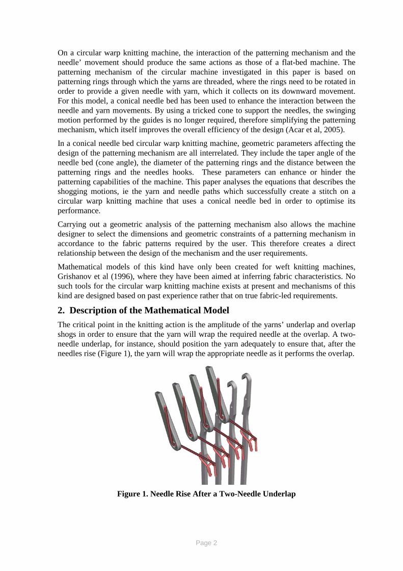
2. Description of the Mathematical Model The critical point in the knitting action is the amplitude of the yarns’ underlap and overlap shogs in order to ensure that the yarn will wrap the required needle at the overlap. A two-needle underlap, for instance, should position the yarn adequately to ensure that, after the needles rise (Figure 1), the yarn will wrap the appropriate needle as it performs the overlap.
Figure 1. Needle Rise After a Two-Needle Underlap
Page 3
A successful overlap shogging motioncombination must also ensure that the yarn will be placed at a position where it will wrap above the spoon of the open latch and under the needle hook. This will guarantee that the overlap will neither wrap the yarn under the needle latch nor slide the yarn above the hook.
By using a mathematical model, the machine designer can predict whether a successful underlap-overlap combination can be achieved with a given set of geometric constraints.
The model is based on creating a set of equations used to predict the intersection of a yarn after the underlap or overlap shogs with the plane in which the target needle moves (that is, the needle on which the next stitch is to be produced). This will enable the designer to investigate the advantages of different values for parameters such as cone taper, cone verge diameter, height of patterning rings and shog amplitude for the creation of a specific fabric pattern.
2.1 Geometric Parameters
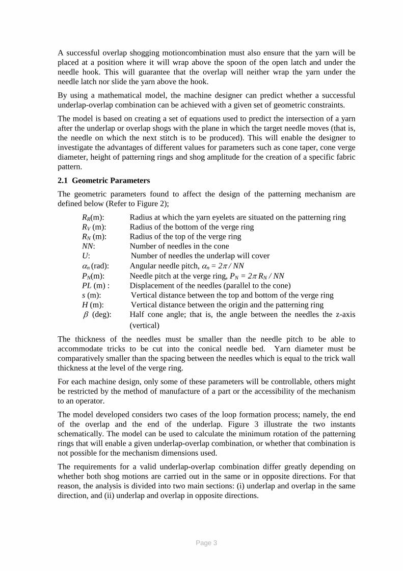
The geometric parameters found to affect the design of the patterning mechanism are defined below (Refer to Figure 2);
RR(m): Radius at which the yarn eyelets are situated on the patterning ring RV (m): Radius of the bottom of the verge ring RN (m): Radius of the top of the verge ring NN: Number of needles in the cone U: Number of needles the underlap will cover αn (rad): Angular needle pitch, αn = 2π / NN PN(m): Needle pitch at the verge ring, PN = 2π RN / NN PL (m) : Displacement of the needles (parallel to the cone) s (m): Vertical distance between the top and bottom of the verge ring H (m): Vertical distance between the origin and the patterning ring β (deg): Half cone angle; that is, the angle between the needles the z-axis
(vertical)
The thickness of the needles must be smaller than the needle pitch to be able to accommodate tricks to be cut into the conical needle bed. Yarn diameter must be comparatively smaller than the spacing between the needles which is equal to the trick wall thickness at the level of the verge ring.
For each machine design, only some of these parameters will be controllable, others might be restricted by the method of manufacture of a part or the accessibility of the mechanism to an operator.
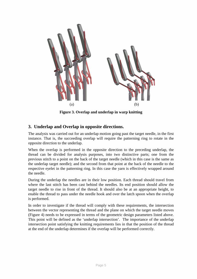
The model developed considers two cases of the loop formation process; namely, the end of the overlap and the end of the underlap. Figure 3 illustrate the two instants schematically. The model can be used to calculate the minimum rotation of the patterning rings that will enable a given underlap-overlap combination, or whether that combination is not possible for the mechanism dimensions used.
The requirements for a valid underlap-overlap combination differ greatly depending on whether both shog motions are carried out in the same or in opposite directions. For that reason, the analysis is divided into two main sections: (i) underlap and overlap in the same direction, and (ii) underlap and overlap in opposite directions.
Page 4
Figure 2. Cone section using plane through target needle
Needle OverlapPosition
Needle UnderlapPosition
x
z
R
PL
R
sV
N
β°
H
RR
Page 5
Figure 3. Overlap and underlap in warp knitting
3. Underlap and Overlap in opposite directions. The analysis was carried out for an underlap motion going past the target needle, in the first instance. That is, the succeeding overlap will require the patterning ring to rotate in the opposite direction to the underlap.
When the overlap is performed in the opposite direction to the preceding underlap, the thread can be divided for analysis purposes, into two distinctive parts; one from the previous stitch to a point on the back of the target needle (which in this case is the same as the underlap target needle); and the second from that point at the back of the needle to the respective eyelet in the patterning ring. In this case the yarn is effectively wrapped around the needle.
During the underlap the needles are in their low position. Each thread should travel from where the last stitch has been cast behind the needles. Its end position should allow the target needle to rise in front of the thread. It should also be at an appropriate height, to enable the thread to pass under the needle hook and over the latch spoon when the overlap is performed.
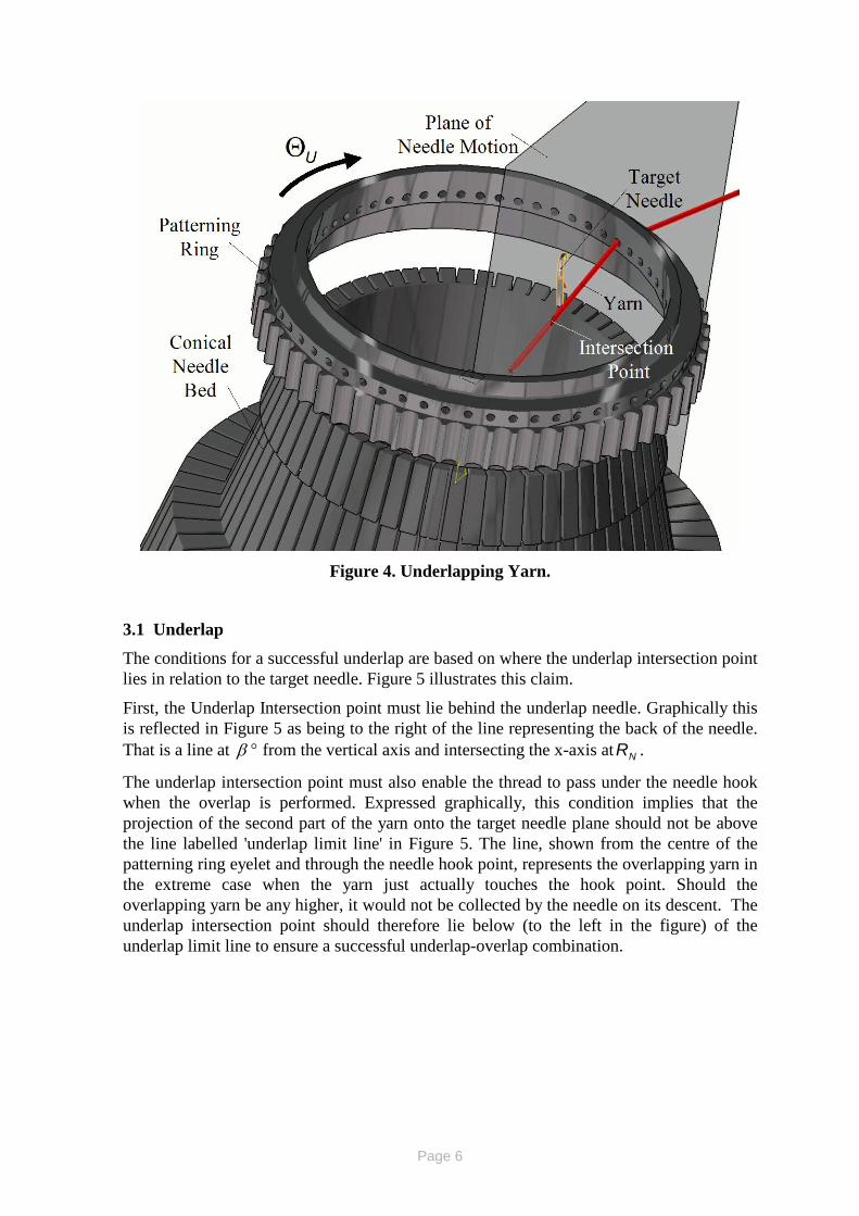
In order to investigate if the thread will comply with these requirements, the intersection between the vector representing the thread and the plane on which the target needle moves (Figure 4) needs to be expressed in terms of the geometric design parameters listed above. This point will be defined as the ‘underlap intersection’. The importance of the underlap intersection point satisfying the knitting requirements lies in that the position of the thread at the end of the underlap determines if the overlap will be performed correctly.
(a) (b)
Page 6
Figure 4. Underlapping Yarn.
3.1 Underlap
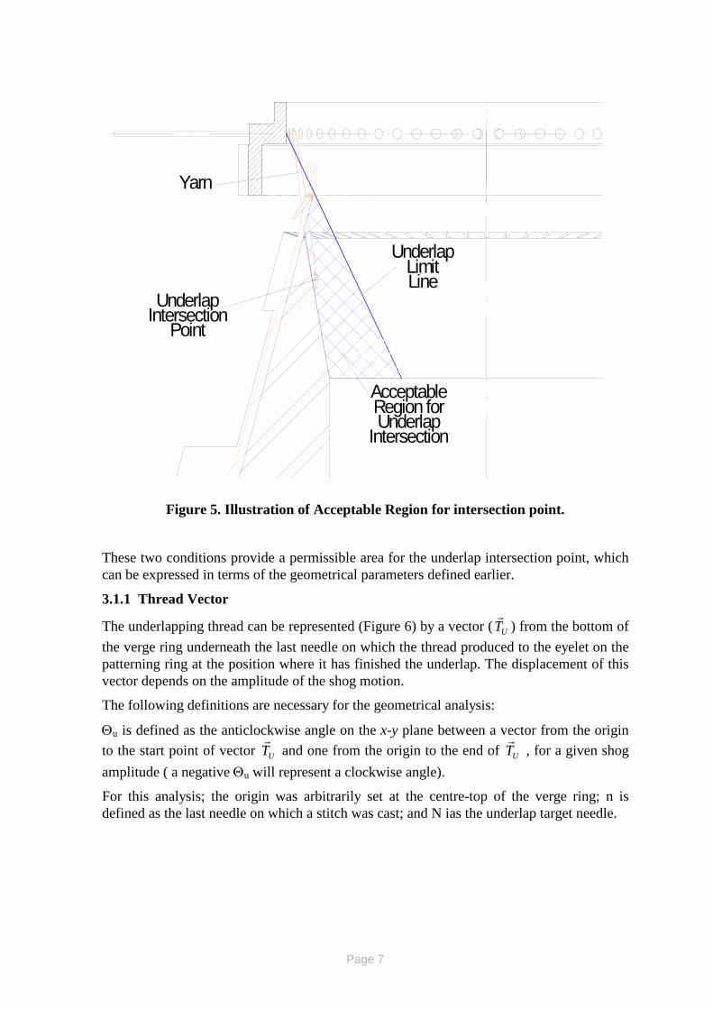
The conditions for a successful underlap are based on where the underlap intersection point lies in relation to the target needle. Figure 5 illustrates this claim.
First, the Underlap Intersection point must lie behind the underlap needle. Graphically this is reflected in Figure 5 as being to the right of the line representing the back of the needle. That is a line at β ° from the vertical axis and intersecting the x-axis at NR .
The underlap intersection point must also enable the thread to pass under the needle hook when the overlap is performed. Expressed graphically, this condition implies that the projection of the second part of the yarn onto the target needle plane should not be above the line labelled 'underlap limit line' in Figure 5. The line, shown from the centre of the patterning ring eyelet and through the needle hook point, represents the overlapping yarn in the extreme case when the yarn just actually touches the hook point. Should the overlapping yarn be any higher, it would not be collected by the needle on its descent. The underlap intersection point should therefore lie below (to the left in the figure) of the underlap limit line to ensure a successful underlap-overlap combination.
Page 7
UnderlapIntersection
Point
UnderlapLimitLine
Yarn
AcceptableRegion forUnderlap
Intersection
Figure 5. Illustration of Acceptable Region for intersection point.
These two conditions provide a permissible area for the underlap intersection point, which can be expressed in terms of the geometrical parameters defined earlier.
3.1.1 Thread Vector
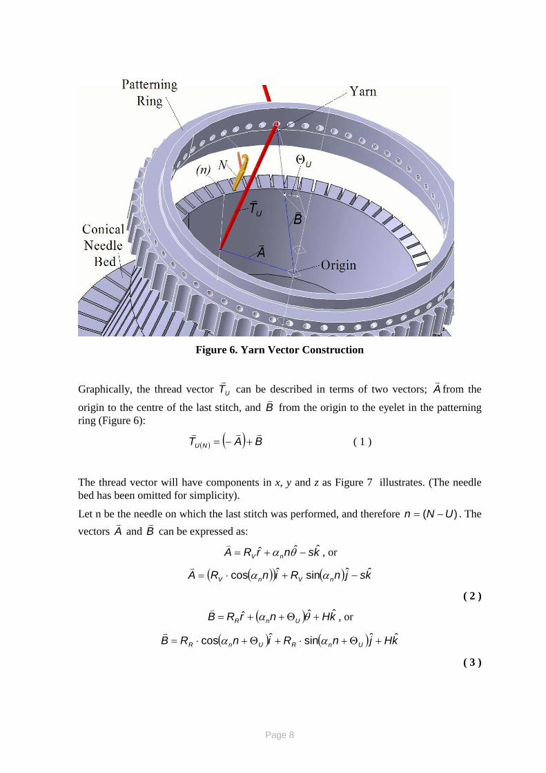
The underlapping thread can be represented (Figure 6) by a vector ( UT
) from the bottom of the verge ring underneath the last needle on which the thread produced to the eyelet on the patterning ring at the position where it has finished the underlap. The displacement of this vector depends on the amplitude of the shog motion.
The following definitions are necessary for the geometrical analysis:
Θu is defined as the anticlockwise angle on the x-y plane between a vector from the origin to the start point of vector UT
and one from the origin to the end of UT
, for a given shog
amplitude ( a negative Θu will represent a clockwise angle).
For this analysis; the origin was arbitrarily set at the centre-top of the verge ring; n is defined as the last needle on which a stitch was cast; and N ias the underlap target needle.
Acceptable Region for
Intersection Point
Page 8
Figure 6. Yarn Vector Construction
Graphically, the thread vector UT
can be described in terms of two vectors; A
from the
origin to the centre of the last stitch, and B
from the origin to the eyelet in the patterning ring (Figure 6):
( ) ( ) BAT NU
+−= ( 1 )
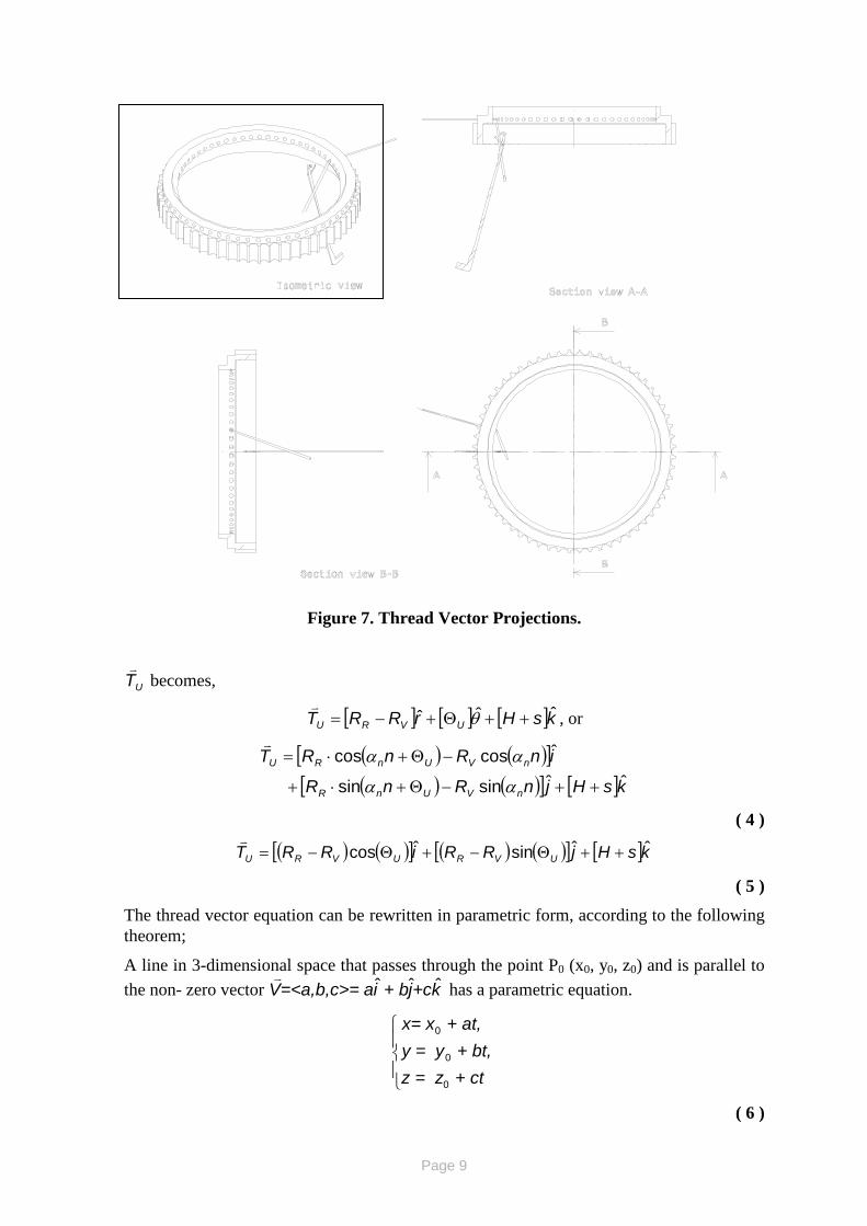
The thread vector will have components in x, y and z as Figure 7 illustrates. (The needle bed has been omitted for simplicity).
Let n be the needle on which the last stitch was performed, and therefore )( UNn −= . The vectors A
and B
can be expressed as:
ksnrRA nVˆˆˆ −+= θα
, or
( )( ) ( ) ksjnRinRA nVnVˆˆsinˆcos −+⋅= αα
( 2 )
( ) kHnrRB UnRˆˆˆ +Θ++= θα
, or
( ) ( ) kHjnRinRB UnRUnRˆˆsinˆcos +Θ+⋅+Θ+⋅= αα
( 3 )
Page 9
Figure 7. Thread Vector Projections.
UT
becomes,
[ ] [ ] [ ]ksHrRRT UVRUˆˆˆ ++Θ+−= θ
, or
( ) ( )[ ]( ) ( )[ ] [ ]ksHjnRnR
inRnRT
nVUnR
nVUnRU
ˆˆsinsin
ˆcoscos
++−Θ+⋅+
−Θ+⋅=
αα
αα
( 4 )
( ) ( )[ ] ( ) ( )[ ] [ ]ksHjRRiRRT UVRUVRUˆˆsinˆcos ++Θ−+Θ−=
( 5 )
The thread vector equation can be rewritten in parametric form, according to the following theorem;
A line in 3-dimensional space that passes through the point P0 (x0, y0, z0) and is parallel to the non- zero vector k+cj + bia=<a,b,c>= V ˆˆˆ
has a parametric equation.
+ ctz = z + bt, y = y
+ at, x= x
0
0
0
( 6 )
Page 10
Using ( ) ( )( ) ,sin,cos000 HnRnR ) = , z , y(x UnRUnR Θ+Θ+ αα and (4) or (3) as V
;
( ) ( ) ( )[ ]( ) ( ) ( )[ ]
[ ]
⋅++=
⋅−Θ++Θ+=
⋅−Θ++Θ+=
tsHHztnRnRnRy
tnRnRnRx
nVUnRUnR
nVUnRUnR
,sinsinsin,coscoscos
αααααα
( 7 )
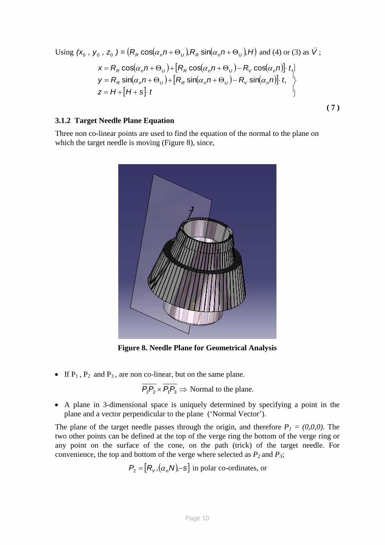
3.1.2 Target Needle Plane Equation
Three non co-linear points are used to find the equation of the normal to the plane on which the target needle is moving (Figure 8), since,
Figure 8. Needle Plane for Geometrical Analysis
• If P1 , P2 and P3 , are non co-linear, but on the same plane.
⇒× 3121 PPPP Normal to the plane.
• A plane in 3-dimensional space is uniquely determined by specifying a point in the plane and a vector perpendicular to the plane (‘Normal Vector’).
The plane of the target needle passes through the origin, and therefore P1 = (0,0,0). The two other points can be defined at the top of the verge ring the bottom of the verge ring or any point on the surface of the cone, on the path (trick) of the target needle. For convenience, the top and bottom of the verge where selected as P2 and P3;
( )[ ]sNRP nV −= ,,2 α in polar co-ordinates, or
Page 11
( )( ) ( )( )[ ]sNRNRP nVnV −= ,sin,cos2 αα in Cartesian co-ordinates.
( 8 )
( )[ ]0,,3 NRP nN α= in polar co-ordinates, or
( )( ) ( )( )[ ]0,sin,cos3 NRNRP nNnN αα= in Cartesian co-ordinates.
( 9 )
The equation of a vector normal to the plane can be obtained by calculating 3121 PPPP × ;
( ) ( )( ) ( ) 0sincos
sincos
ˆˆˆ
3121
NRNRsNRNR
kjiPPPP
NNNN
NVNV
αααα −=×
( 10 )
( )( ) ( )( )( ) ( ) ( ) ( )( )kNNRRNNRR
jNRsiNRsPPPP
nnVNnnVN
nNnN
ˆcossincossin
ˆcosˆsin3121
αααα
αα
−+
⋅−⋅=×
( 11 )
( )( ) ( )( ) jNRsiNRsPPPP nNnNˆcosˆsin3121 αα ⋅−⋅=×
( 12 )
The equation of the plane can be rewritten as
0000 ) = (z-z) + C (y-y) + B(x-xA PPP
( 13 )
Taking ),,= (xyx P 000),,( 0000 ;
0z = y + Cx + BA PPP ⋅⋅⋅
( 14 )
0cossin y=N) (x - sRN) (sR nNnN ⋅⋅ αα
( 15 )
3.1.3 Intersection Point
The intersection point between the needle plane and the thread vector can be defined as;
( )
+=
+=
+=
=≡
II
II
II
IIII
ctzzbtyyatxx
zyxP
0
0
0
,,
( 16 )
where t I can be found by substituting ( )III zyx ,, equations onto the equation of the plane: equation (15).
Using the same notation for the coefficients in equations (13) and (6), and noting that the intersection point must comply with the equation of the plane;
Page 12
0 = z + Cy + BxA IPIPIP ⋅⋅⋅
( ) ( ) ( ) 0000 = atz + Cbty + BatxA IPIPIP +⋅+⋅+⋅∴
( )( )cCbBaA
zCyBxAtPPP
PPPI ++
++−=∴ 000
( 17 )
We can now substitute the expression for It into equation (16) to find the co-ordinates of the intersection point;
( )
( )( )( )( )
( )( )
++++−
+=
++++−
+=
++++−
+=
=≡
cCbBaAzCyBxA
czz
cCbBaAzCyBxA
byy
cCbBaAzCyBxA
axx
zyxP
PPP
PPPI
PPP
PPPI
PPP
PPPI
IIII
0000
0000
0000
,,
( 18 )
where;
( )UnR n = Rx Θ+αcos0 ,
( ) sin0 UnR n Ry Θ+= α ,
0 = Hz ,
( ) ( )[ ]nRnRa nVUnR αα coscos −Θ+= ,
( ) ( )[ ]nRnRb nVUnR αα sinsin −Θ+= ,
[ ]sHc += ,
N) (sRA nNP αsin= ,
( )N - sRB nNP αcos= ; and,
0=CP .
Having determined the equations defining the co-ordinates of the underlap intersection point, its suitability can only be determined if the equations of the lines representing the back of the needle and the 'Underlap Limit' are known.
The underlap-overlap combination is successful if ( )IIII zyxP ,,≡ satisfies two inequalities indicating being under the underlap limit line and the line of the back of the needle.
3.2 Overlap
In the case of the underlap and overlap in opposite directions, the overlap movement is the less critical one, as the underlap has already ensured that the motion can be performed. When the overlap movement starts, the needles are at their highest position. As the ring starts to rotate in the opposite direction, the side of the each needle will hold the thread.
Page 13
In this case the overlap angle should only be sufficient to ensure that the thread has swung to the opposite side of the target needle.
4. Underlap and Overlap in the Same Direction In the case where the underlap and overlap making a stitch are performed in the same direction, both shog motions can be treated as a single rotation of the ring by adding their amplitudes.
The intersection of the yarn vector after the compound shog with the plane on which the target needle moves (in this case not the same as the underlapping one) will define whether the complete motion is possible.
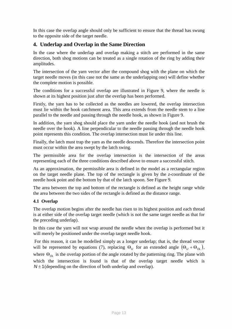
The conditions for a successful overlap are illustrated in Figure 9, where the needle is shown at its highest position just after the overlap has been performed.
Firstly, the yarn has to be collected as the needles are lowered, the overlap intersection must lie within the hook catchment area. This area extends from the needle stem to a line parallel to the needle and passing through the needle hook, as shown in Figure 9.
In addition, the yarn shog should place the yarn under the needle hook (and not brush the needle over the hook). A line perpendicular to the needle passing through the needle hook point represents this condition. The overlap intersection must lie under this line.
Finally, the latch must trap the yarn as the needle descends. Therefore the intersection point must occur within the area swept by the latch swing.
The permissible area for the overlap intersection is the intersection of the areas representing each of the three conditions described above to ensure a successful stitch.
As an approximation, the permissible area is defined in the model as a rectangular region on the target needle plane. The top of the rectangle is given by the z-coordinate of the needle hook point and the bottom by that of the latch spoon. See Figure 9.
The area between the top and bottom of the rectangle is defined as the height range while the area between the two sides of the rectangle is defined as the distance range.
4.1 Overlap
The overlap motion begins after the needle has risen to its highest position and each thread is at either side of the overlap target needle (which is not the same target needle as that for the preceding underlap).
In this case the yarn will not wrap around the needle when the overlap is performed but it will merely be positioned under the overlap target needle hook.
For this reason, it can be modelled simply as a longer underlap; that is, the thread vector will be represented by equations (7), replacing UΘ for an extended angle ( )OLU Θ+Θ , where OLΘ is the overlap portion of the angle rotated by the patterning ring. The plane with which the intersection is found is that of the overlap target needle which is
1±N (depending on the direction of both underlap and overlap).
Page 14
YarnAcceptableRegion forOverlap
IntersectionOverlap
IntersectionPoint
Figure 9. Acceptable Area Overlap Intersection
4.2 Underlap
Once the minimum valid overlap angle is found, the underlap angle will be the largest angle for which the underlap target needle (that is, the one adjacent to the overlap needle) can rise in front of the yarn. That is, the underlap intersection point is behind the vector representing the needle stem.
5. Shog Angles Calculation Algorithm The algorithm developed to calculate shogging angles is the means of attaining the objective of forecasting the patterning capability of the patterning mechanism before committing to a specific design. The goal of the algorithm is to predict whether an underlap-overlap combination is possible for a mechanism with a given set of geometric parameters.
The process carried for each of the two main cases is described in the flowcharts of Figure 10 and Figure 11. As it can be seen from the flowchart, either branch of the flowchart will
Overlap Intersection
Point
Yarn Acceptable Region for Overlap Intersection
Page 15
yield results for minimum overlap and underlap rotations or a message stating that the stitch cannot be completed using the parameters defined for the mechanism.
This is an invaluable tool for the designer of patterning mechanisms, as they will know in advance whether the combination of underlapand overlap required could be performed by the mechanism designed. However, the goal of the model is not only to predict whether given combinations are possible once the design has been carried out, but also to provide the designer with the best values for the geometric parameters. A design can then be manufactured based on the suggested parameter values, in the knowledge that all the underlap-overlap combinations required will be attainable.
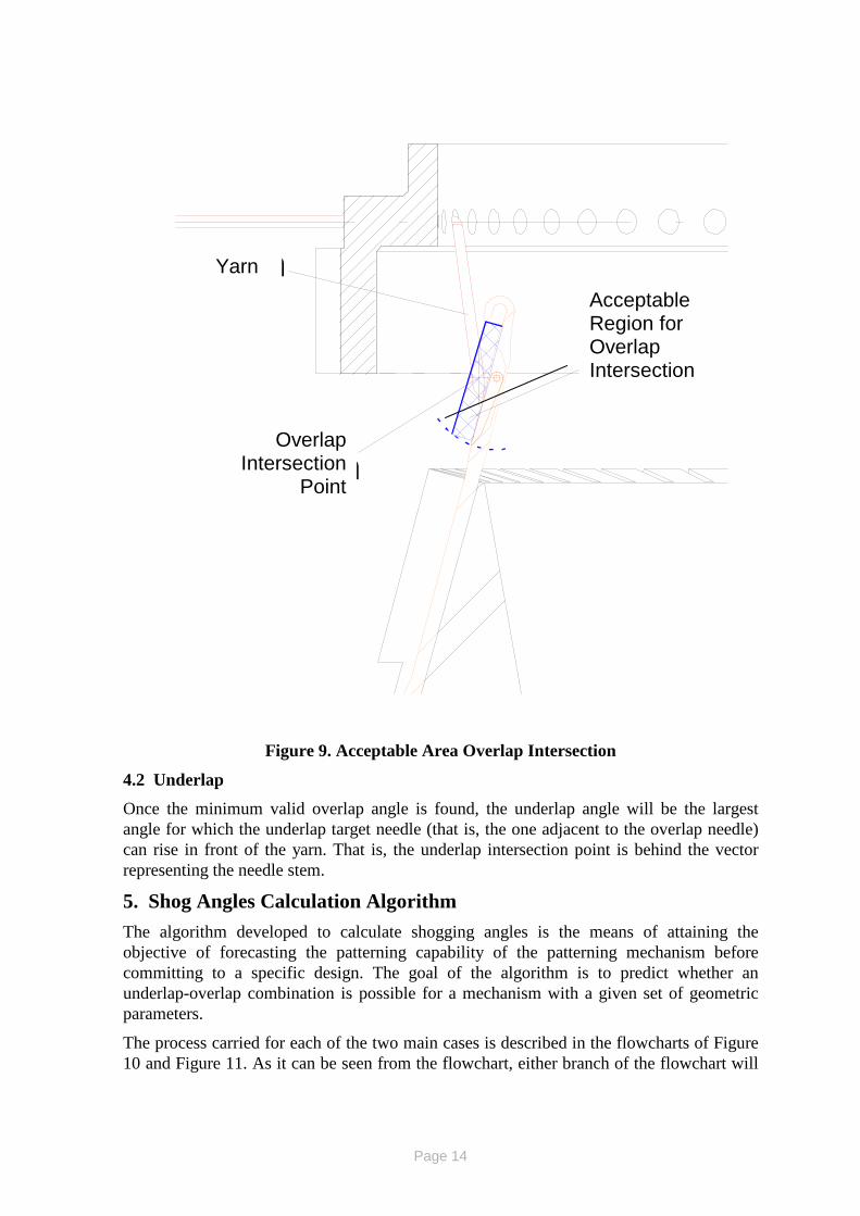
5.1 Underlap and Overlap in the Same Direction
The algorithm flowchart to find the overlap and underlap angles is shown in Figure 10. After the designer has entered the geometric parameters, the overlap target needle plane, the equations of the lines surrounding the acceptable area are calculated as these will not change. The overlap angle is initialised as zero and will be incremented on each loop (in the overlapping direction) while the overlap intersection is not within the acceptable area shown in Figure 9. This ensures that the overlap angle found is the minimum angle that will provide with an acceptable underlap-overlap combination.
Every time the angle is incremented a thread vector is defined for the new angle, and with this, an intersection point will be calculated. At the beginning of the next iteration, this point is evaluated on the set of inequalities that define the acceptable area, in order to decide whether or not to enter a new loop.
The conditions of the iterative loop ensure that the intersection point does not enter and exit either the height or the distance range (as defined in section 4), as that would imply that the overlap is not possible.
To illustrate this point, let the overlap intersection point found for 1Θ be within the distance range but outside and above the height range. The next iteration, when the ring has rotated
δ+Θ1 gives a new intersection point, nearer the needle stem but still above the height range. If, after i iterations, the intersection point occurs outside of both ranges (i.e. it has entered and exited the distance range), the overlap will not be possible because the yarn will not re-enter the distance range.
Page 16
Define Parameters
Underlap & overlap in the
same direction?
While Intersection of thread out of
acceptable area
Increment O/L angle
Calculate Intersection of thread vector with
O/L needle plane
Calculate boolean variables defining in & out of range condition.
Y
If NOT (In & Out of
good area)
If NOT(In & Out of Height
Range).
“O/L not possible. In & Out of distance range”
“O/L not possible. In & Out of height range”
Y
N N N
N
While yarn behind needle
and not touching
Decrease O/L angle
Calculate Intersection of thread vector with U/L needle plane
Calculate boolean variables for behind needle
If NOT Behind Needle
“U/L not possible.U/L needle can’t clear yarn”
N N
Y
Y
“O/L & U/L possible.ØO/L= xx, ØU/L =xx.”
Y
Figure 10. Flowchart for Overlap and Underlap in the same Direction
Should this happen, the algorithm ends by recording that the overlap is not possible and the cause of the failure to find one.
If a satisfactory overlap intersection point is found on the other hand, the overlap angle is recorded and an associated underlap angle is found by another iterative process.
In order to consider the underlap part of the movement, a new target needle plane is calculated using the underlap needle (that is, the one adjacent to the overlap target needle).
The underlap angle is initialised as OU Θ=Θ , the successful overlap found, and decreased on each iteration. In this case there is only one condition for a satisfactory underlap intersection, namely that it lies behind the needle stem.
If the underlap angle reaches the underlap target needle angle (i.e. NNU ⋅=Θ α ) and the intersection point is not behind the needle, then the underlap cannot be performed. This can occur especially in small gauge machines, where the spacing of the needles does not allow a yarn to be laid behind a needle and in front of the adjacent one.
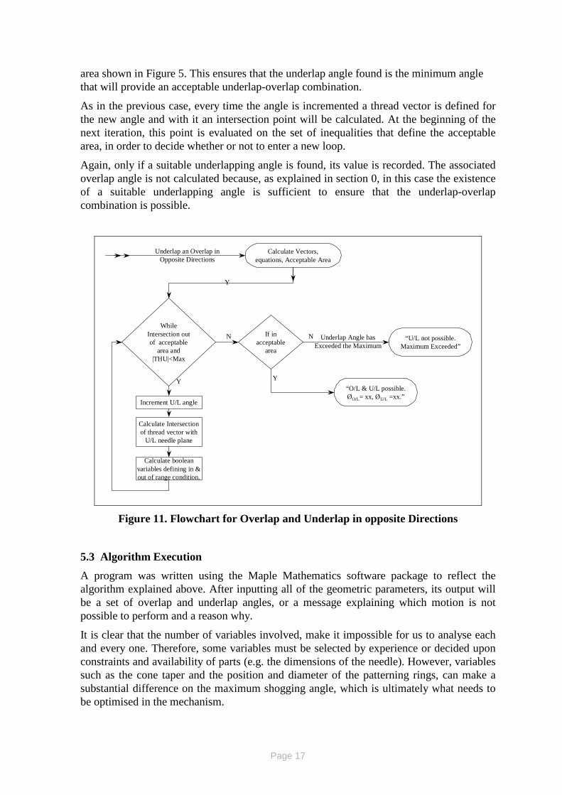
5.2 Underlap and Overlap in Opposite Directions
The algorithm flowchart to find the overlap and underlap angles for this case is shown in Figure 11. After the designer has entered the geometric parameters, the underlap target needle plane, and the equations of the lines surrounding the acceptable area are calculated, as these will not change. The overlap angle is initialised as the angle required to place the yarn exactly above the target needle )( NNU ⋅=Θ α , and will be incremented on each loop (in the underlapping direction) while the underlap intersection is not within the acceptable
Page 17
area shown in Figure 5. This ensures that the underlap angle found is the minimum angle that will provide an acceptable underlap-overlap combination.
As in the previous case, every time the angle is incremented a thread vector is defined for the new angle and with it an intersection point will be calculated. At the beginning of the next iteration, this point is evaluated on the set of inequalities that define the acceptable area, in order to decide whether or not to enter a new loop.
Again, only if a suitable underlapping angle is found, its value is recorded. The associated overlap angle is not calculated because, as explained in section 0, in this case the existence of a suitable underlapping angle is sufficient to ensure that the underlap-overlap combination is possible.
Calculate Vectors, equations, Acceptable Area
While Intersection out of acceptable
area and |THU|<Max
Increment U/L angle
Calculate Intersection of thread vector with
U/L needle plane
Calculate boolean variables defining in & out of range condition.
Y
If in acceptable
area
“U/L not possible.Maximum Exceeded”
N N
Y“O/L & U/L possible.ØO/L= xx, ØU/L =xx.”
Y
Underlap Angle has Exceeded the Maximum
Underlap an Overlap in Opposite Directions
Figure 11. Flowchart for Overlap and Underlap in opposite Directions
5.3 Algorithm Execution
A program was written using the Maple Mathematics software package to reflect the algorithm explained above. After inputting all of the geometric parameters, its output will be a set of overlap and underlap angles, or a message explaining which motion is not possible to perform and a reason why.
It is clear that the number of variables involved, make it impossible for us to analyse each and every one. Therefore, some variables must be selected by experience or decided upon constraints and availability of parts (e.g. the dimensions of the needle). However, variables such as the cone taper and the position and diameter of the patterning rings, can make a substantial difference on the maximum shogging angle, which is ultimately what needs to be optimised in the mechanism.
Page 18
The design process of the knitting head of a circular warp knitting machine should mainly depend on the fabrics intended to be manufactured on it. The size and material of the yarns to be used largely define the needle types and gauges that can be used. On the other hand, the size and tightness of the fabric approximately define the cone diameter (except in the case of nets) and the machine gauge respectively.
The fabric specification determines the maximum number of needles to underlap in a single motion. The model explained in the sections above provides with a means of deciding on selected geometric parameters involved.
The machine designer can predict if the fabrics specified could be manufactured and change the knitting head design accordingly. Potentially, the model and the program can reduce the cost of re-work substantially, as the lack of a geometric model can result in a incorrect design and consequently, loss of time and money.
6. Circular Warp Knitting Case The algorithm was used to analyse the effect of varying the cone taper angle on the range of fabrics that could be produced with the machine. The bending force applied to the strengthening inserts will increase as the cone taper angle increases. Therefore, the optimum design would be the one that allows the underlap-overlap combinations required for the fabrics intended to be produced, using smallest cone taper angle.
The design of a 3" (76.2mm) diameter circular warp knitting machine head with 60 needles was used for the study. The needle specification was defined by the types of yarns to be used.
The geometric parameters used can be summarised as follows;
• RR = 1.595 inches (40.51mm).
• RV = 1.347 inches (34.21mm).
• RN = 1.492 inches (37.90mm).
• αn = 6 °.
• PL = 0.866 inches (22.01mm).
• s = 0.565 inches (14.35mm).
• H = 0.813 inches (20.65mm).
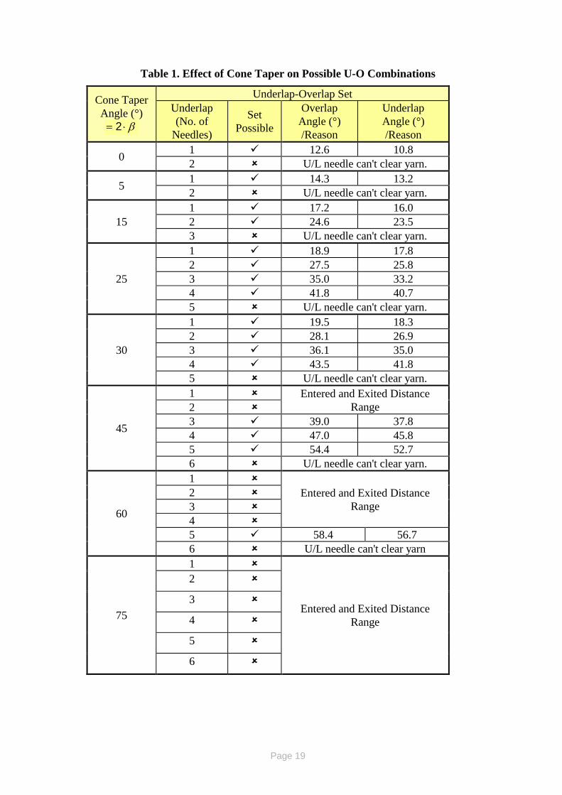
The objective of the case study is to analyse the effect of varying the cone taper angle on the possible underlap-overlap (U-O) combinations. Table 1 illustrates the results for U-O combinations in the same direction, which is generally more difficult to achieve than the equivalent U-O in opposite directions.
It is seen from Table 1 that the effect of the cone taper angle is not straightforward. Although for smaller taper angles, an increase in the taper leads to longer underlaps being possible, once the taper reaches 45 degrees, it is the smaller underlaps that become impossible to perform. Moreover, once the taper angle reaches 75 degrees, no underlap is possible.
Page 19
Table 1. Effect of Cone Taper on Possible U-O Combinations
Cone Taper Angle (°)
β⋅= 2
Underlap-Overlap Set Underlap (No. of
Needles)
Set Possible
Overlap Angle (°) /Reason
Underlap Angle (°) /Reason
0 1 12.6 10.8 2 U/L needle can't clear yarn.
5 1 14.3 13.2 2 U/L needle can't clear yarn.
15 1 17.2 16.0 2 24.6 23.5 3 U/L needle can't clear yarn.
25
1 18.9 17.8 2 27.5 25.8 3 35.0 33.2 4 41.8 40.7 5 U/L needle can't clear yarn.
30
1 19.5 18.3 2 28.1 26.9 3 36.1 35.0 4 43.5 41.8 5 U/L needle can't clear yarn.
45
1 Entered and Exited Distance Range 2
3 39.0 37.8 4 47.0 45.8 5 54.4 52.7 6 U/L needle can't clear yarn.
60
1 Entered and Exited Distance
Range 2 3 4 5 58.4 56.7 6 U/L needle can't clear yarn
75
1
Entered and Exited Distance Range
2
3
4
5
6
Page 20
From these results, the designer can safely conclude that the taper used for the cone should be less than 45 degrees. It would be very difficult to predict this outcome without a geometric model.
On the other hand, the overlap and underlap angles required for a single-needle underlap increase as the cone taper increases. An increase in the underlap angle implies a reduction of speed in the patterning mechanism (as the ring will have to travel further). Therefore, the designer of a circular warp knitting machine to be used for manufacturing fabrics requiring up to two-needle underlaps will probably choose to design the cone with a 15 degree taper. Smaller cone taper angles are desirable from the kinetics considerations of the needle support plate drive and its effects on the forces exerted on the strengthening inserts.
Similar analyses can be applied to other design variables. For instance, for a machine equipped with several patterning rings, each ring will be positioned at a different height; it is therefore useful to know the effect of varying the height and diameter of the different rings on the underlapping possibilities before being committed to a given design.
7. Conclusions The geometrical relationships between the patterning and knitting mechanisms in a circular warp knitting machine are not easy to visualise and determine. The geometrical model described here is an invaluable aid for the designer to maximise the machine's performance.
The circular warp knitting machine case study shows how the model described here can be used to alter design parameters according to the fabric intended to be produced. The case study has also demonstrated that the patterning capabilities are increased for these particular geometric parameters up to a cone taper angle of about 30°. It has also shown how the effect of increasing the cone taper angle on the patterning capabilities of the machine becomes detrimental for angles greater than 45°. This proves that there is an optimum value for a given set of geometric parameters and that the optimum value can be found using the algorithm proposed.
References Acar, M., Mermelstein, S. and Jackson, M.R., ''Design and Development of a Mechatronic Circular Warp Knitting Machine'' , Proc. Mechatronics 2002 , Twente, Netherlands, 24th June 2002, 12 pp
Grihanov, S. A., Cassidy, T. and Spencer, D., (1996), Loop Formation: A mathematical model of loop forming on the knitting machine, Textile Horizons, Vol. 16, Part 1
Acknowledgements Financial support from Teaching Company Directorate and Tritex International is gratefully acknowledged.


![STRUCTURE AND PROPERTIES OF HIGH SYMMETRY …Weft knitting is the oldest form of knitting. The first weft knit machine was invented about 1589 (12]. Weft knitting involves the formation](https://img.pdfslide.net/doc/110x75/5fe2311f78d1a608921317b9/structure-and-properties-of-high-symmetry-weft-knitting-is-the-oldest-form-of-knitting.jpg)