Embed Size (px)
Citation preview

MOJO 40 ARFInstruction Manual
Wing Span: 46"Weight: 4 - 4.5 lbs. -Wing Area: 704 Sq. In.Wing Load: 13 Oz / sq. ft
Engine: .46-.53 2-stroke or .63-.82 4-stroke glowRadio Gear: 5 Channel Radio, 5 standard servosManufactured by Nikitis AircraftDistributed exclusively by Billy Hell RC

Page: 1
Dear Customer, Congratulations on your purchase of The MOJO ARF! It is one of the first ARF kits designed by Paul Swanson, produced right here in the USA by Nikitis Aircraft Company, and distributed by Billy Hell RC. You are unique in owning one of our newest products from our newest division. You are also in a place to help us improve our product. In order for Nikitis Aircraft Company and Billy Hell RC to become one of the best producers of American Made ARF kits, we encourage your input and suggestions. We ask that you make our company aware of errors and/or imperfections in the kit or instructions that may have occurred, or simply your thoughts about your new model. As with any new product there is room for improvement and our intent is to make every product we have better. Overall we hope you’ll find the MOJO ARF to be an excellent plane. Please feel free to contact us at (937) 726-0845 or email us at [email protected]. On behalf of Eddie Noble, Billy Hell, Paul Swanson, and the Nikitis Aircraft employees, we thank you for supporting an American company and hope you enjoy your MOJO ARF. Disclaimer: By purchasing and/or building this model, user assumes ALL liability and risk involved with this product. This model should be built and flown by an experienced pilot and only flown at AMA sanctioned sites. BHRC/Nikitis guarantees this model to be free of defects in materials and workmanship at the date of purchase. This warranty does not cover any parts damaged by use or modifications. In no way shall BHRC/Nikitis liability exceed the original cost of the purchased model. Further, BHRC/Nikitis reserves the right to modify this warranty without notice. BHRC/Nikitis has no control over the final stages of assembly or the material used for the final assembly. No liability shall be assumed nor materials used for the final user-assembled product. By the act of using the final product the user accepts all resulting liability. BHRC/Nikitis, as a kit/ARF distributor, provides a top quality kit/ARF and instructions to complete the model. The quality and flight characteristics of the finished model depends greatly on how it is built; we cannot guarantee the performance for the completed model and representations are expressed or implied as to the performance of the completed model. If the buyer is not prepared to accept the liability associated with the use of this product, the buyer is advised to return this kit immediately, in new and unused condition, to the place of purchase.

Page: 2
Table of Contents
• Introduction ····································· Page 1 -
• Table of Contents ·································· Page 2 -
• Kit Contents ····································· Page 3 -
• Required Equipment ······························· Page 4 -
• Required Additional Hardware ························ Page 4 -
• Recommended Tools and Supplies ······················ Page 4 -
• Graphics Application ······························· Page 5 -
• Assembly Guide ··································· Page 6 -
o Tube preparation ····························· Page 6 Steps 1-4
o Gluing Engine Mount to Tube ···················· Page 6 Steps 5-7
o Gluing Fuselage to Wing ························ Page 7 Steps 8-12
o Ply Gear Mount Installation ····················· Page 8 Step 13
o Aligning Fuselage to Wing ······················ Pages 8-9 Steps 14-20
o Mounting the Horizontal Stabilizer ················ Pages 9-10 Steps 21-28
o Epoxy/micro-balloon Fillet ······················ Pages 10-11 Steps 29-31
o Check Elevator Clearance ······················ Page 11 Step 32
o Rudder Installation ··························· Page 11 Steps 33-34
o Landing Gear Installation ······················ Pages 11-12 Steps 35-39
o Mount Tail Servos ···························· Pages 12-13 Steps 40-44
o Tail Servo Extension Preparation ················· Pages 13-14 Steps 45-49
o Feed Extensions Thru Tube······················ Pages 14-15 Steps 50-55
o Hinge Ailerons ······························ Page 15 Step 56
o Aileron Servo Installation ······················ Pages 15-16 Steps 57-63
o Antenna Installation ·························· Page 17 Steps 64-67
o RX Switch Installation ························· Pages 17-18 Steps 68-71
o Throttle Servo Mount ························· Pages 18-19 Steps 72-79
o Motor Installation ···························· Pages 19-20 Steps 80-83
o Throttle Servo Linkage ························ Pages 20-21 Steps 84-88
o Fuel Tank Mounting ·························· Page 21 Steps 89-92
o Finish Up, Check Center of Gravity ··············· Page 22 Steps 93-94
• User Notes ······································ Page 22 -
Page: 3
Kit Contents:
1. Wing 2. Fuselage 3. Ply Motor Mount 4. Fiberglass tube 5. Horizontal Stabilizer 6. Elevator 7. Rudder 8. Left and Right Aileron 9. White vinyl graphics (2 sheets, not shown) 10. Graphics layout sheet (not shown) 11. Hardware pack, which includes:
a. Landing gear wire b. Landing gear mounting blocks (2) c. Ply landing gear mount d. Hatches for wing e. Control horns and mounting screws f. Triangle-shaped stab braces
Page: 4
Required Equipment (not included):
• Engine: o .40 to .50ci 2-stroke (i.e. OS 46AX, Webra 50, OS 50SX) or o .60 to .82ci 4-stroke (i.e. Saito .72, YS 63, Saito .82)
• Radio: o 5-channel TX/RX recommended. o Five (5) servos:
§ Four (4) standard-BB or better for surfaces (i.e. Futaba 3010) § One (1) mini or better for throttle (i.e. Hitec HS-85)
o Two (2) ~12” extensions for tail servos. o 600mah or larger receiver battery of choice. o Charge switch of choice.
Required Additional Hardware (not included):
• Mounting Bolts for your Engine (4-40 Stainless recommended) • Washers for 2.5° motor right thrust, or buy thrust-wedges from SwanysHouse.com. • Throttle linkage hardware (2-56 with pushrod housing recommended) • Side-mount for throttle servo (make or buy, build instructions are included). • Fuel tank and plumbing/foam/mounting-hardware. (6-8oz recommended) • Control surface hardware of choice (4-40 and ball-links recommended) • Hinges of choice. (good quality CA or point hinges) • Main wheels and 5/32” collars (2.5" wheel is suggested). • Hardware to hold the wire gear on (4-40 x 1.5" bolts, washers, locknuts). • Tailwheel assembly of choice.
Recommended Tools and Supplies (not included):
• 30 minute epoxy • Micro-balloons • Poly Glue (i.e. “Gorilla Glue”) • CA glue, Thin, Medium, and Thick • Sandpaper • Dremel or similar rotary tool with cutting bits/wheels. • Weights to hold things down while glue sets • Heat Gun (or a hairdryer works in a pinch) • Soldering Iron • Covering Iron • Misc screwdrivers, hex drivers, etc for hardware chosen.

Page: 5
Graphics application: To give you a chance to change the trim scheme, to personalize your MOJO ARF for yourself, the graphics have not been applied from the factory. To install “S” graphics, remove from paper backing. Spray the back of the graphic (the sticky side) with windex, as well as the surface it will be applied to. Next align graphic on to model according to the included graphics placement sheet. When satisfied, use a squeegee or credit card and gently squeeze excess windex from under the graphic. Leave stand for several minutes to allow the ammonia in the windex to dry. This completes the “S” graphic application. The letter graphics will be applied differently than the “S” graphics. To apply letter graphic, the process of transfer tape is used. Using scissors, cut individual graphics into sections. Leave as much on the sides as you can for something to grab hold of. Gently peel clear transfer tape from the paper backing. Notice that the graphic should stick to the transfer tape. Position graphic in place and press firmly until sealed to covering. Next gently peel clear transfer tape away from the graphic. Be careful not to lift the letters.
Page: 6
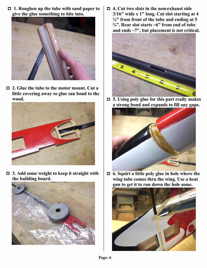
p 1. Roughen up the tube with sand paper to
give the glue something to bite into.
p 2. Glue the tube to the motor mount. Cut a little covering away so glue can bond to the wood.
p 3. Add some weight to keep it straight with
the building board.
p 4. Cut two slots in the non-exhaust side 3/16" wide x 1" long. Cut slot starting at 4 ¾" from front of the tube and ending at 5 ¾”. Rear slot starts ~6” from end of tube and ends ~7", but placement is not critical.
p 5. Using poly glue for this part really makes
a strong bond and expands to fill any gaps.
p 6. Squirt a little poly glue in hole where the
wing tube comes thru the wing. Use a heat gun to get it to run down the hole some.
Page: 7
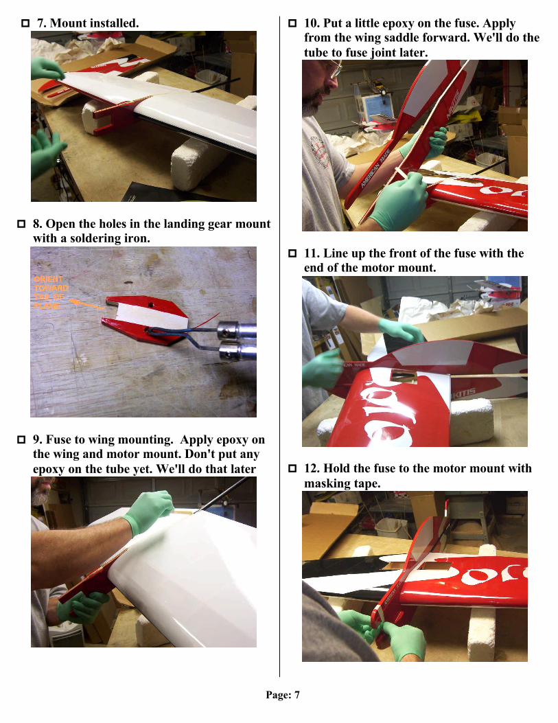
p 7. Mount installed.
p 8. Open the holes in the landing gear mount
with a soldering iron.
p 9. Fuse to wing mounting. Apply epoxy on
the wing and motor mount. Don't put any epoxy on the tube yet. We'll do that later
p 10. Put a little epoxy on the fuse. Apply from the wing saddle forward. We'll do the tube to fuse joint later.
p 11. Line up the front of the fuse with the
end of the motor mount.
p 12. Hold the fuse to the motor mount with
masking tape.
Page: 8
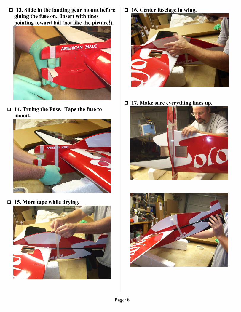
p 13. Slide in the landing gear mount before
gluing the fuse on. Insert with tines pointing toward tail (not like the picture!).
p 14. Truing the Fuse. Tape the fuse to
mount.
p 15. More tape while drying.
p 16. Center fuselage in wing.
p 17. Make sure everything lines up.

Page: 9
p 18. More fuse alignment
p 19. Make sure it's true. Sight it and you'll
see if anything needs adjusting.
p 20. Use some thin CA to tack the tube to
the fuse. We'll put a nice fillet of epoxy and micro balloons later.
p 21. Mounting the Horizontal Stab. Mark the center of the stab.
p 22. Draw a line on the center using the
mark you made.
p 23. Cut the tube at a 45 for elevator
clearance. Just match the angle on the lower fuse piece.

Page: 10
p 24. Cut the covering back a little and glue
the first piece of tri stock to the stab on the mark 1/4" from the centerline.
p 25. Hinge the stab to the elevator and slide
in the elevator in the fuselage first.
p 26. Slide the hinges in before gluing. Then
glue with some epoxy top and bottom.
p 27. Glue on the other piece of tri stock.
p 28. Make sure the horizontal stabilizer is
level with the wing.
p 29. Use 30 minute epoxy with micro
balloons. Make a nice thick paste. Drizzle the epoxy mixture in the joint.

Page: 11
p 30. Use a heat gun to flow out the epoxy.
p 31. Fill any gaps between the wing and
fuse.
p 32. Make sure you have sufficient elevator
clearance for the throws you want.... I like 50° - 60°.
p 33. Slot the rudder for hinges. I like to use Radio south hinges. I use a 1/4 scale CA hinge for the lower hinge on the rudder.
p 34. Glue rudder hinges, check movement.
p 35. Install landing gear. Hardware used is
shown:
Page: 12
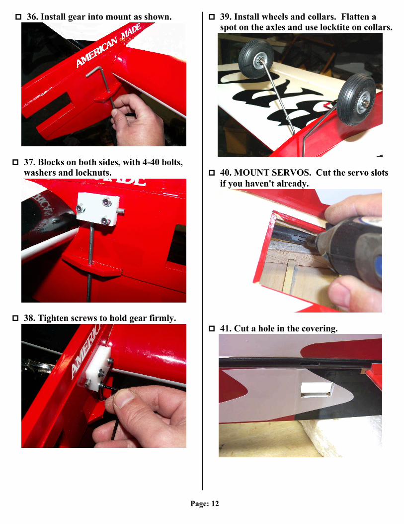
p 36. Install gear into mount as shown.
p 37. Blocks on both sides, with 4-40 bolts,
washers and locknuts.
p 38. Tighten screws to hold gear firmly.
p 39. Install wheels and collars. Flatten a spot on the axles and use locktite on collars.
p 40. MOUNT SERVOS. Cut the servo slots if you haven't already.
p 41. Cut a hole in the covering.

Page: 13
p 42. Load the servo with the pig tail on the
side of the servo.
p 43. Servo mounted with the pig tail out of
the "goo trail".
p 44. Servo detail.
p 45. Running servo wires down the tube,
especially Futaba connectors with are wide... made easier by removing connector-housing.
Page: 14
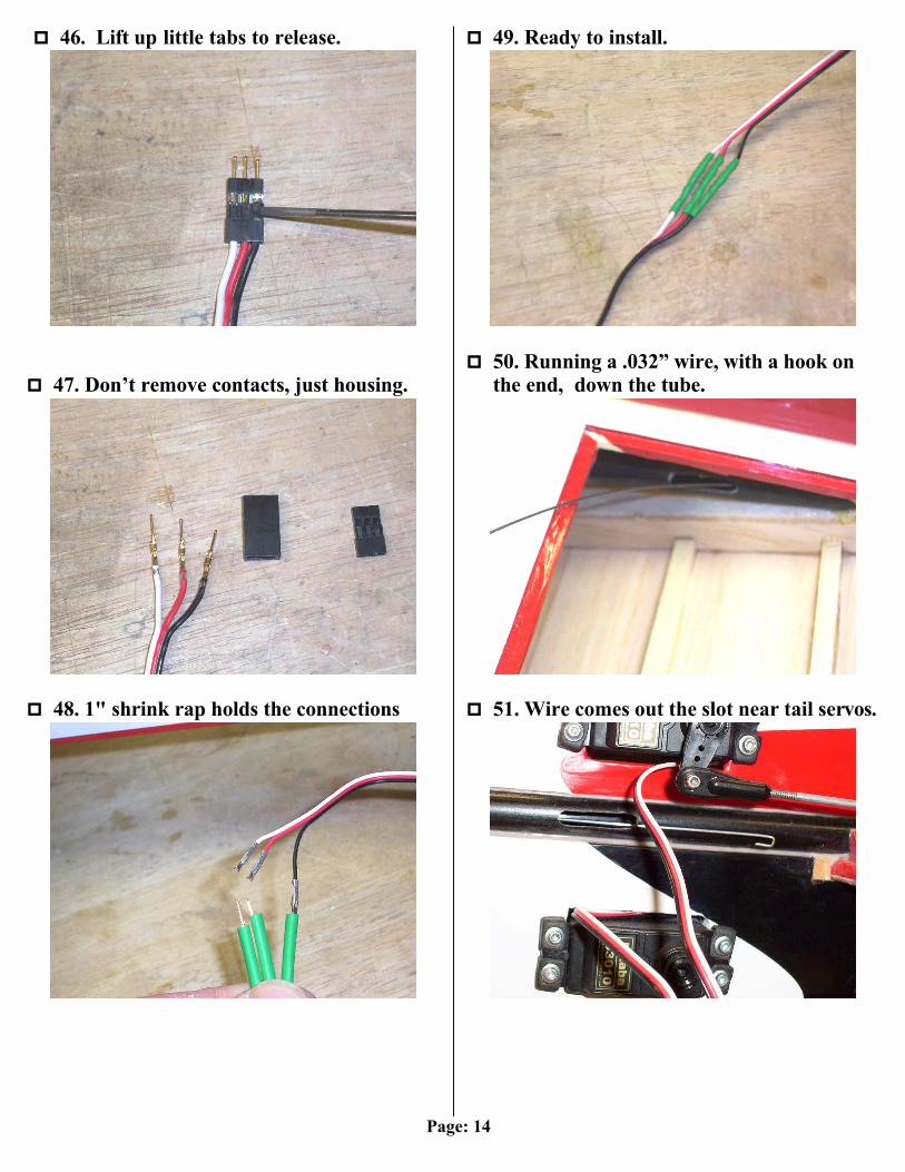
p 46. Lift up little tabs to release.
p 47. Don’t remove contacts, just housing.
p 48. 1" shrink rap holds the connections
p 49. Ready to install.
p 50. Running a .032” wire, with a hook on
the end, down the tube.
p 51. Wire comes out the slot near tail servos.
Page: 15
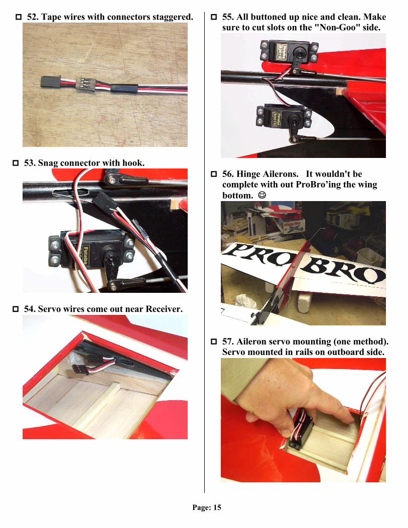
p 52. Tape wires with connectors staggered.
p 53. Snag connector with hook.
p 54. Servo wires come out near Receiver.
p 55. All buttoned up nice and clean. Make sure to cut slots on the "Non-Goo" side.
p 56. Hinge Ailerons. It wouldn't be
complete with out ProBro’ing the wing bottom. ☺☺
p 57. Aileron servo mounting (one method).
Servo mounted in rails on outboard side.
Page: 16
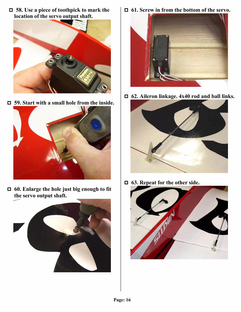
p 58. Use a piece of toothpick to mark the
location of the servo output shaft.
p 59. Start with a small hole from the inside.
p 60. Enlarge the hole just big enough to fit
the servo output shaft.
p 61. Screw in from the bottom of the servo.
p 62. Aileron linkage. 4x40 rod and ball links.
p 63. Repeat for the other side.

Page: 17
p 64. Antenna Installation. Use a piece of
1/16" music wire. Grind one end sharp and poke it thru the tip rib.
p 65. Poke the wire into the radio bay.
p 66. CA the antenna to the wire.
p 67. Pulled thru.
p 68. Switch Install. Example shows Dubro
charging jack and switch mount.
p 69. Mark where to cut the hole.
Page: 18
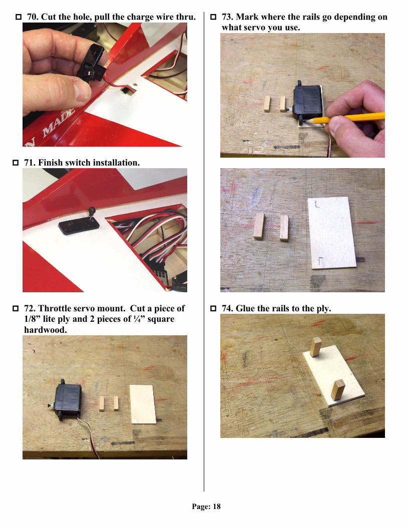
p 70. Cut the hole, pull the charge wire thru.
p 71. Finish switch installation.
p 72. Throttle servo mount. Cut a piece of
1/8” lite ply and 2 pieces of ¼” square hardwood.
p 73. Mark where the rails go depending on what servo you use.
p 74. Glue the rails to the ply.
Page: 19
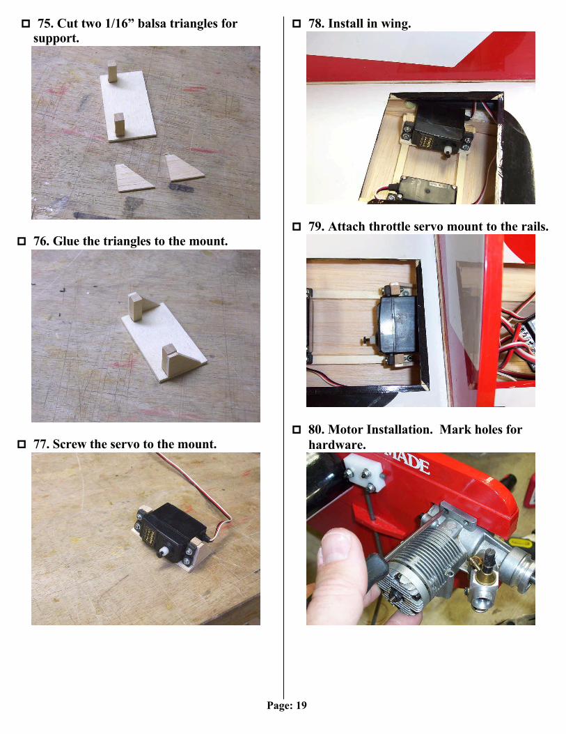
p 75. Cut two 1/16” balsa triangles for
support.
p 76. Glue the triangles to the mount.
p 77. Screw the servo to the mount.
p 78. Install in wing.
p 79. Attach throttle servo mount to the rails.
p 80. Motor Installation. Mark holes for
hardware.
Page: 20
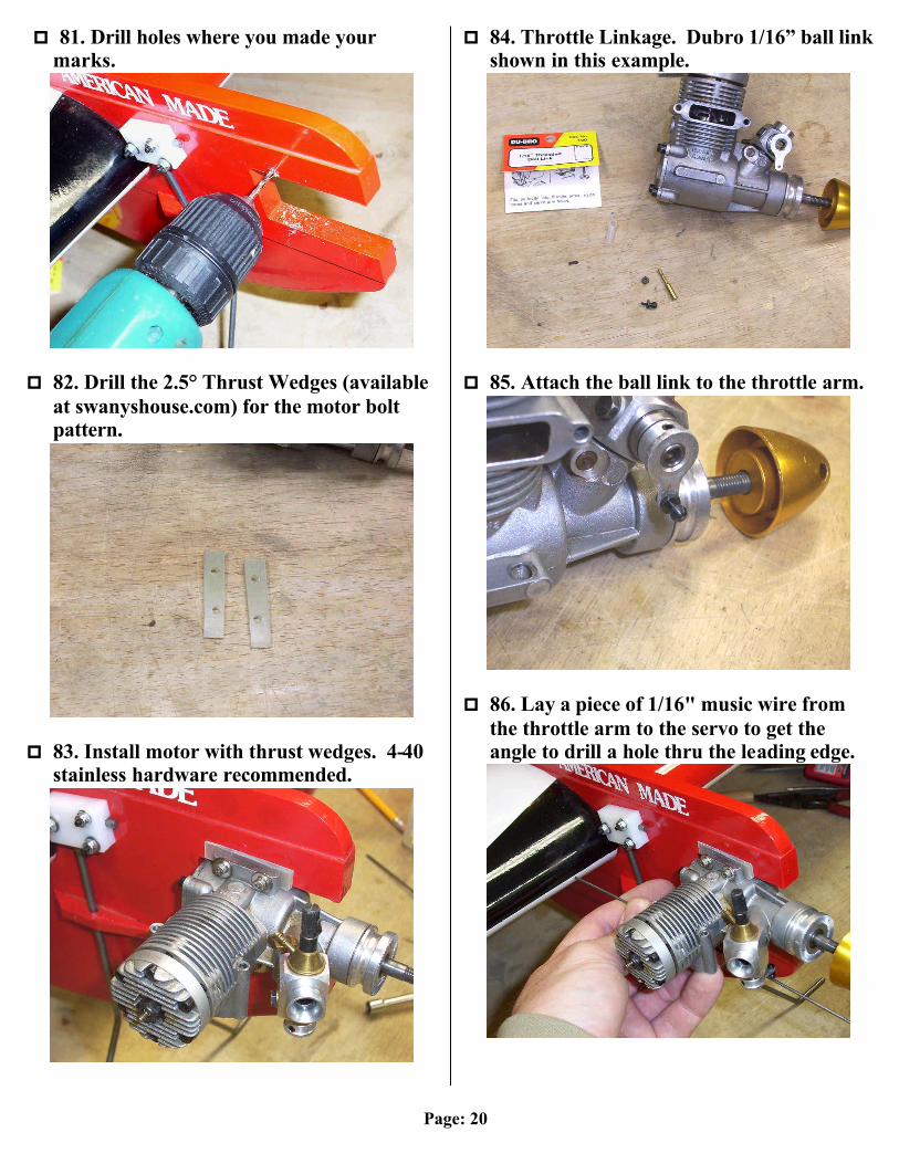
p 81. Drill holes where you made your
marks.
p 82. Drill the 2.5° Thrust Wedges (available
at swanyshouse.com) for the motor bolt pattern.
p 83. Install motor with thrust wedges. 4-40
stainless hardware recommended.
p 84. Throttle Linkage. Dubro 1/16” ball link shown in this example.
p 85. Attach the ball link to the throttle arm.
p 86. Lay a piece of 1/16" music wire from
the throttle arm to the servo to get the angle to drill a hole thru the leading edge.

Page: 21
p 87. Linkage to the servo. Easy connector
shown.
p 88. Finished throttle installation.
p 89. Fuel Tank Mounting (one method).
Mark and drill 4 holes to attach the tank.
p 90. Insert some left over control rod into the holes.
p 91. Bend hooks in the wire.
p 92. Use some rubber bands to hold it on.
Use good closed cell foam behind tank.
Page: 22
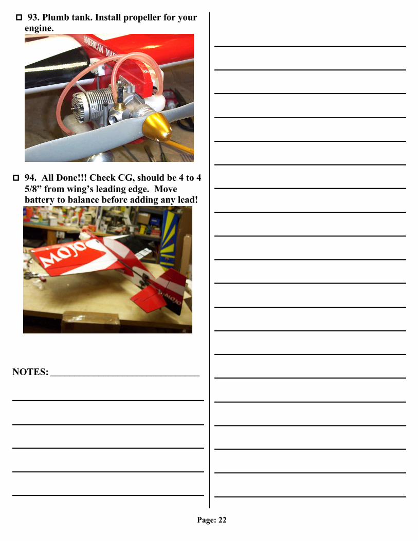
p 93. Plumb tank. Install propeller for your
engine.
p 94. All Done!!! Check CG, should be 4 to 4
5/8” from wing’s leading edge. Move battery to balance before adding any lead!
NOTES: _______________________________