Embed Size (px)
Citation preview

AD-fli58 197 MRGNETIC FIELD INTERRCTIONS WITH NATERIAL 1/1DISCONTINUITIES(U) COLORRDO STRTE UNIV FORT COOLINSDDPT OF ELECTRICAL ENGINEERING W LORD OCT 84
UNCLASSIFIED ARO-i7923.i-MS DAAG29-8i-K-0ii5 F/G 20/3 N
1111.0 14. 1 28 12.511111 ,____o ,
Ll 6
IIIII5III
1111 .2 11 In l.4 1 .
MICROCOPY RESOLUTION TEST CHARTNATIONAL BUREAU OF STANDARDS 1963 A

Magnetic Field Interactions
with Material Discontinuities
0?-: ARO Final Report
October 1984
9i
Prepared for the U.S. Army Research Ofifice
m-under Contract DAAG29-81-K-0115
W. Lord, Principal Investigator
*. , . .,__, 3 *
1i~)
I NCTASSTFT F111(CURITY CLASSIFICATION OF THIS PAGE (Whon One t. eed)
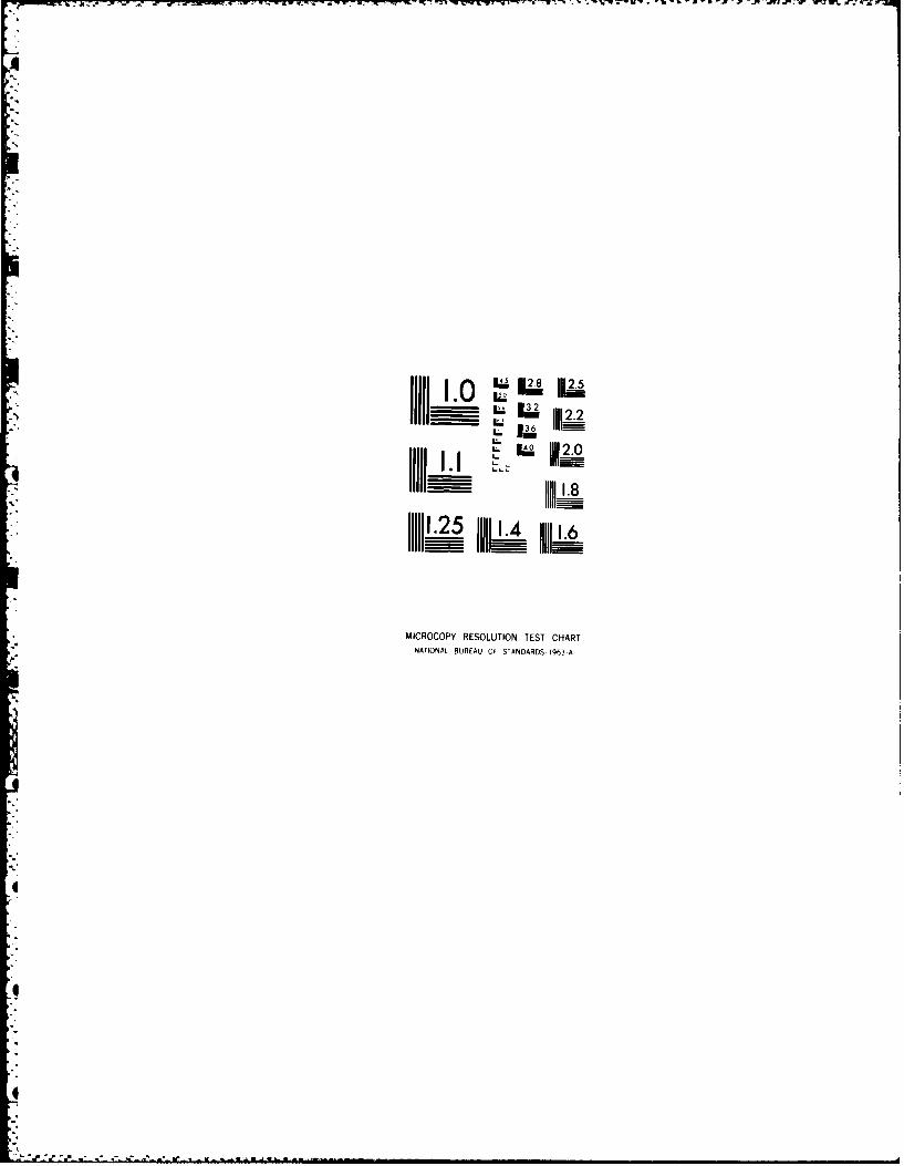
REOTDCMNAINPAGE READ INSTRUCTIONSREPOR DOCMENTTIONBEFORE COMPLETING F~ORM
I. REORT UMSERTACC1 5S7111N 3. RECIPIENT'S CATALOG NUMUIERARO 17923.1-MS AIA:'!NIA
4. TITLE (and Subtitle) S. TYPE OF REPORT & PERIOO COVERED
MAGNETIC FIELD INTERACTIONS WITH MATERIAL 15 Jun 81 - 14 Sep 84DISCONTINUITIES FnlRpr
6 . PERFORMING OPG. REPORT NumER
7AUTHOR(@) S. CONTRACT OR GRANT NuMSER(o)
W. LordDAA29-81-K- 0115
S. PERFORMING ORGANIZATION NAMIE AND) ADDRESS 10. PROGRAM ELEMENT. PROJECT. TASKC
Department of Electrical Engineering AREA & WORK UNIT MUERS
Colorado State University N/AFort Collins, CO 80523
11. CONTROLLING OFFICE NAME AND ADDRESS 12. REPORT DATE
U. S. Army Research Office October, 1984Post Office Box 12211 .NUBROPAE
RgP~rch &r~ pl-~~I.C2~~14. MONITORING AGENCYAME a A6RffW(ii dLfut from Core~olI~d office) 15. SECURITY CLASS. (.1 Ohio tpo~)
N/A Ucasfe
IS. DISTRIBUTION STATEMENT (of this Rep..t)
Approved for public release; distribution unlimited.
* 17. DISTRIBUTION STATEMENT (of thme abstract entered Block D It differet fma Repojtt
NA
IS. SUPPLEMENTARY NOTES%
The view, opinions, and/or findings contained in this report arethose of the author(s) and should not be construed as an officialDepartment of the Army position, policy, or decision, unless sod cdgnre bynhtpr dne',mptatinn-
15.~~~~~a rE OD (mtnea. vere* side it necessary and identify by. block ninmber)
*'Niondestructive testing, active leakage fields, residual leakage fields,eddy current NDT, numerical modeling, finite element analysis, defectcharacterization
2& ATrmAcCwft stare oon. hf wneuea"I Md Iderwily by block nuotbor)
All methods of nondestructive testing (NDT) rely for their operation on theinteraction of an energy source with defects in the material under test. Suchinteractions are extremely difficult to model analytically because of theawkward boundari 'es associated with realistic defect shapes and the Inhere~ntnonlinear behavior of many material properties. The major contrIbut ion of
* this project work has been to show that finite element analysis techniquescan be used to model electromagnetic energy/defect interactions associated
D W43 CLtTIow oF I NOV65s is oBSOLETE- UNCLASSIFIEDKSECUONrv CLASSIFICATION, oF rhis PAGE (When Date Entered)

tN IAN I V I 11)111CU PITY CLASSIICATION OF THIS PAGSR(Wha Data Easet1
Vith active leakage field, residual leakage field, eddy current and pulsededdy current NDT methods.
'Developed code has been used to study probe design, to simulate testinggeometries too difficult to replicate in a laboratory environment and toaid in the development of defect characterization algorithms. C. %,
- Acces.sion For
7'1
~~.o
°Ell
UNCLASSIFIED* \ \ SaCURITY CLASSIFICATION OF THIS PAGE(Wh..n Does Entered)
% --. . " . . _". . . . . . j , - . -. . .[ '

Table of Contents
Falte No.
1. Background 3
2. Summry of Results 5
3. Publications 6
4. Participating Scientific Personnel 8
5. Future Work 8
6. References 9
7. Appendix 1 12
7a. Appendix 11 23

Magnetic Field Interactions
with Material Discontinuities
by
W. Lord
Abstract
All methods of nondestructive testing (NDT) rely for their operation
on the interaction of an energy source with defects in the material under
test. Such interactions are extremely difficult to model analytically
because of the awkward boundaries associated with realistic defect shapes
and the inherent nonlinear behavior of many material properties. The major
contribution of this project work has been to show that finite element
analysis techniques can be used to model electromagnetic energy/defect
interactions associated with active leakage field, residual leakage field,
eddy current and pulsed eddy current NDT methods.
Developed code has been used to study probe design, to simulate
testing geometries too difficult to replicate in a laboratory environment
and to aid in the development of defect characterization algorithms.
-2-

1. Background
Electromagnetic methods of nondestructive testing are used widely
throughout the aerospace, transportation, ordnance, metals and energy
industries for detecting defects in critical metal parts. A major
stumbling block in the development of these techniques, particularly with
regard to the study of automated defect characterization schemes and
associated imaging systems, has been the lack of a suitable model capable
of predicting the inherently complex field/defect interactions.
Over the past decade, with Army Research Office support, the NDT
laboratory at Colorado State University has pioneered in the use of tinite
element analysis techniques to solve the modeling problem for active and
residual leakage field as well as eddy current NDT methods
With the advent of the digital computer, increasing emphasis has been
placed on the numerical solution of partial differential equations. In the
late 1960s Erdelyi2 showed how the finite difference method of
approximating partial derivatives could be applied to the prediction of
electromagnetic fields in electrical machinery. At about the same time
3 4Winslow and Silvester and Chari demonstrated that finite element
techniques, based on variational calculus, could be applied to the same
problems. A period of acrimonious debate followed in the power apparatus
5and systems literature as to the relative merits of the two approaches
Based on the author's experience in the early 197U's of applying
finite element analysis to the study o electromagnetic fields in magnetic
structures 6 , it became clear that such techniques would be ideally suited
to the study of electromagnetic NDT phenomena because of the ease vith
which the awkward defect boundaries could be handled.
With a small "seed-money" grant from the Colorado Energy Research
. .-3-

Institute in 1974, initial work was undertaken to develop finite element
code for the study of leakage fields around defects in a cylindrical shaped
bar carrying an axial dc excitation current - the "active" case. Based on
promising preliminary results from the CERI study 8 a proposal was
submitted to the Army Research Office in 1975. The major objectives of the
ARO study were to a) extend the preliminary results to a wider variety of
defect shapes, b) determine the feasibility of extending the finite
element code to the residual leakage field (magnetic particle) NDT
situation and c) explore the possibility of applying finite element
analysis techniques to a study of eddy current NDT phenomena. Following
successful completion of these objectives 9-4, further work was initiated
via an ARO follow-on proposal aimed at extending the studies to:
15a) The examination of an unusual leakage field reversal phenomena
b) three dimensional magnetostatic. finite element code 6
17.1
c) pulsed eddy current phenomena1 1 , and
d) deconvolution effects in Hall element measurements of19magnetostatic leakage fields
In short, Army Research Office support of studies in the Applied
Magnetics and NDT Laboratory at Colorado State University relating to
electromagnetic field/defect interactions have clearly shown the
feasibility and usefulness of applying finite element analysis techniques
20,21as a modeling tool *In addition, funding from the Electric Power
Research Institute has demonstrated the applicability of such a modeling
tool to practical NDT problems of interest to the nuclear industry 223
All this work has clearly shown the close interrelationship between
models of active, residual and eddy current NDT phenomena, thus paving the
way for a unified approach to the problem of modeling electromagnetic
field/defect interactions2 .:
4 -4-

In carrying out the modeling studies it has also become apparent that
the finite element code has a number of potential uses:
a) An an "experimental model" for simulation of electromagnetic NDTsituations too difficult or expensive to replicate in a laboratoryenvironment.
b) As an aid to the physical understanding of the interactionsbetveen electromagnetic fields and defects in the part under test.
c) As a design tool foz the study of alternative probe geometries.
d) As a training mechanism for the development of automated defectcharacterization schemes.
e) As a technique for estimating the bulk properties (conductivityand permeability) of materials under test. The procedure consistsof iterating the finite element code vith different propertyvalues until the code predictions agree with experimentalobservations.
2. Summary of Results
Finite element code has been developed for the following
electromagnetic NDT testing situations:
a) Active leakage fields:
1. 2-dimensional.
2. Axisymmetric.
3. 3-dimensional.
b) Residual leakage fields:
1. 2-dimensional.
c) Single frequency eddy current:
1. 2-dimensional.
2. Axisymmetric.
3. 3-dimensional.
d) Pulsed eddy current:
1. Axisymmetric.
In addition, experimental work has been carried out using the test rig
-5- W
:.-] .- i. ' -" [":-- /-. :].....,..."......."-.- '""- " '" . - "- • '" '." " " ,. ...-

shown schematically in Figure 1. This has allowed confirmation of the
developed finite element code and led to some novel studies of leakage
field reversal phenomena 15 , Hall-element deconvolution 1 9 and the imaging of
magnetostatic leakage fields and eddy current signals 3 1 (see Figs. 2 and
3). Initial work has also begun on the application of tinite element code
32to the simulation of ultrasonic NDT phenomena
.
3. Publications
From April 1980 to September 1984 the following journal publications
have been written with support from ARO:
A survey of electromagnetic methods of nondestructive testing, Chapter3 in the text Mechanics of Nondestructive Testing, edited by W.W.Stinchcomb, Plenum Press, 1980, pp. 77-100.
Finite element analysis of eddy current phenomena, MaterialsEvaluation, Vol. 38, No. 10, Oct. 1980, pp. 39-43.
Development of theoretical models for NDT eddy current phenomena, inEddy Current Characterization of Materials and Structures, ASTM STP722, G. B. Birnbaum and G. Free, Eds., ASTM, 1981, pp. 5-21.
Developments in the finite element modeling of eddy current NDTPhenomena at CSU, ibid, pp. 357-361.
Numerical modeling of electromagnetic NDT phenomena, in New Proceduresin Nondestructive Testing, P. Holler, Editor, Springer-Verlag, 1983,pp. 461-470.
3-D finite element prediction of magnetostatic leakage fields, IEEETransactions on Magnetics, Vol. MAG-19, No. 5, September 1983, pp.2260-2265.
Eddy current probe design using finite element analysis, MaterialsEvaluation, Vol. 41, No. 12, November 1983, pp. 1389-1394 (with N.Ida and R. Palanisamy). ASNT 1984 Achievement Award.
Applications of numerical field modeling to electromagnetic methods ofnondestructive testing, IEEE Transactions on Magnetics, Vol. MAC-19,No. 6, November 1983, pp. 2437-2442.
Solution of linear equations for small computer systems, InternationalJournal for Numerical Methods in Engineering, Vol. 20, No. 4, April1984, pp. 625-641 (with N. Ida).
Superposition of eddy current probe signals, Materials Evaluation,Vol. 42, No. 7, June 1984, pp. 930-933 (with D.Horne and S. Udpa).
-6-
* ..- .. .

VAX 11/780
RAMTEXDISPLAY
Figure 1. Proposed imaging System Design.
7,m.
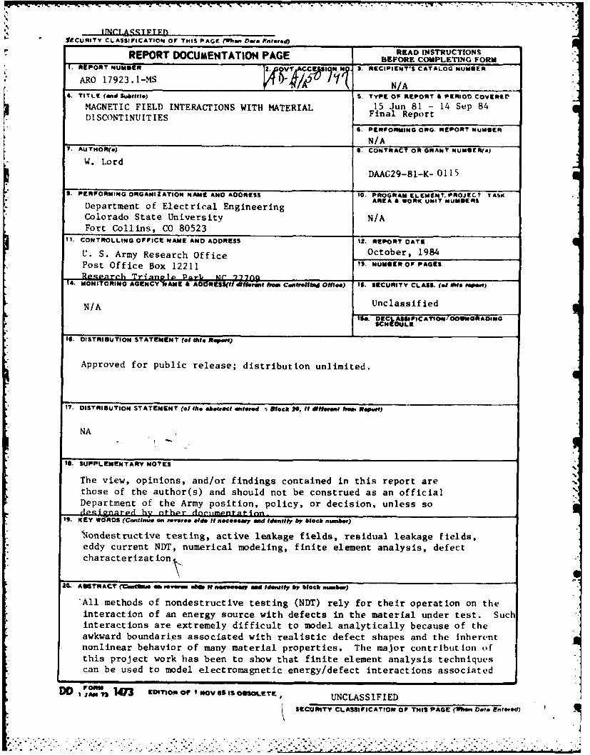
(b)
Figure 2. Active (a) and residual (b) leakage field prof Iles above aa rectangular slot in a ferromagnetic bar.
* * .y.*- . V *~
(a)
L z
Pq(b)
2-
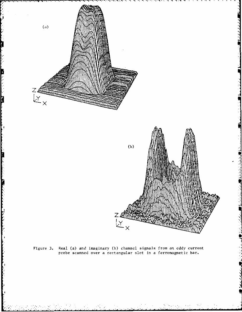
Figure 3. Real (a) and imaginary (b) channel signals from an eddy currentprobe scanned over a rectangular slot in a ferromagnetic bar.
IINI I I I I

Finite element modeling ot pulsed eddy current phenomena, in Review ofProgress in Quantitative Nondestructive Evaluation, D. 0. Thompson andD. E. Chimenti, Eds., Plenum, 1984, pp. 561-568 (with B. Allen).
Deconvolution of defect leakage field profiles obtained by using Hall
element probes, ibid, pp. 855-862 (with L. Srinivasan).
In addition, the following conference presentations have been made:
Modeling residual and active leakage fields, an invited paperpresented at the ASNT Fall Conference, Houston, Oct., 1980.
Recent developments in electromagnetic NDT methods, an invited paperpresented at the Symposium on Novel NDE Methods for Materials, AIMEAnnual Meeting, Dallas, Texas, February 1982.
NDE Education/Training for Engineers, ASME-PVP Annual Meeting,Orlando, June 1982.
Numerical modeling of electromagnetic NDT phenomena, an invited paperpresented at the German-American Workshop on NDT Research andDevelopment, Saarbrucken, W. Germany, August 1982.
Eddy current techniques and their potential for determining materialproperties, an invited paper presented at tue Symposium onNondestructive Methods for Material Property Determination, Hershey,PA, April 1983.
Applications of numerical field modeling to electromagnetic methods ofNDT, an invited paper presented at COMPUMAG, Genoa, Italy, May 1983.
Residual and active magnetic leakage field modeling, presented atQualTest II, Dallas, October 1983.
Numerical modeling of eddy current NDE, an invited paper presented atthe 29th Annual Conference on Magnetism and Magnetic Materials,Pittsburgh, November 1983.
The case for numerically modeling electromagnetic NDT phenomena,presented at the Seminar on Nondestructive Inspection of FerromagneticMaterials, Dresser Industries, Houston, March, 1984.
A new technique for modeling hysteresis loop phenomena, presented atan Eddy Current Seminar, Rutherford Appelton Laboratory, Abingdon,Oxford, U.K., April 1984.
NDT Education at Colorado State University, The case for numericalmodeling of electromagnetic NDT phenomena, both papers presented atthe ASNT Sprint Conference, Denver, May 1984.
Nondestructive evaluation in electrical engineering, presented at theASEE Annual Conference, Salt Lake City, June 1984.
-7-S1

4,- V.
Diffusion, waves, phase and eddy current imaging, presented at theReview of Progress in Quantitative NDE, La Jolla, CA, July 1984 (withL. Udpa).
A finite element formulation for ultrasonic NDT modeling, presented atthe Review of Progress in Quantitative NDE, La Jolla, CA, July 1984(with R. Ludwig).
4. Participating Scientific Personnel
Several graduate students have been associated with the project during
the 1980-84 time frame including:
R. Palanisamy - Ph.D., 1980. Currently a senior NDT researchengineer with the Timken Co., Canton, Ohio.
S. Udpa (Satish) - Ph.D., 1983. Currently an Assistant Professorof Electrical Engineering, Colorado State University.
N. Ida - Ph.D., 1983. Currently an Assistant Professor
of Electrical Engineering, University of Akron.
L. Udpa (Srinivasan) - Ph.D. student at Colorado State University.
R. Ludwig - Ph.D. student at Colorado State University.
B. L. Allen - M.S., 1983. Research engineer with RockwellInternational.
S. Heath - M.S., 1983, Engineer with Hewlett Packard.
C. Wang - Currently completing his Ph.D. degree at NorthCarolina.
W. Lord has been principal investigator throughout.
5. Future Work
This project has clearly shown the feasibility of applying finite
element analysis to the modeling of all electromagnetic NDT phenomena.
Additional funding has been requested from ARO to extend this work to the
application of imaging for the display of results from electromagnetic NDT
methods. Use of the finite element code will aid in the development of
imaging inverse algorithms.
-8-..' -. ' '"" " "" " """"S , ~i I : :

6. References
I. Lord, W.: Magnetic field interactions with material discontinuities.ARO Final Progress Report, DAAG29-76-G-0249, April, 1980.
2. Erdelyi, E. A.: et al. Nonlinear magnetic field analysis of dcmachines. IEEE Trans. PAS. 89 (1970) 1546-1583.
3. Winslow, A. M.: Numerical solution of the quasilinear Poissonequation in a nonuniform triangle mesh. J. Comp. Phys. 2 (1967) 149-172.
4. Silvester, P., Chari, M.V.K.: Finite element solution of saturablemagnetic field problems. IEEE Trans. PAS. 89 (1970) 1642-1651.
5. Demerdash, N. A., Nehl, T. W.: An evaluation of the methods of tiniteelements and finite differences in the solution of nonlinearelectromagnetic fields in electrical machines. IEEE Trans. PAS. 98(1979) 74-87.
6. Lord, W., Hwang, J. H.: Convergence and mesh subdivision for finiteelement analysis of nonlinear magnetic fields. Int. J. Comp. Elec.Eng. 1 (1974) 513-520.
7. Hwang, J. H., Lord, W.: Finite element analysis of the magnetic fielddistributions inside a rotating ferromagnetic bar. IEEE Trans. MAG.10 (1974) 513-520.
8. Lord, W., Hwang, J. H.: Finite element modeling of magnetic fielddefect interactions. ASTM. J. Test, Eval. 3 (1975) 21-25.
9. Lord, W., Hwang, J. H.: Defect characterization from magnetic leakagefields. Brt. J. NDT. 19 (1977) 14-18.
10. Lord, W.: et al. Residual and active leakage fields around defects inferromagnetic materials. Mat. Eval. 36 (1978) 47-54.
11. Palanisamy, R., Lord, W.: Finite element modeling of electromagneticNDT phenomena, IEEE Trans. MAC, 15 (1979) 1479-1481.
12. Lord, W.: A survey of electromagnetic methods of nondestructivetesting. Mechanics of Nondestructive Testing, Stinchcomb, W. W. (ed.)Plenum Press (1980) 77-100.
13. Palanisamy, R., Lord, W.: Finite element analysis of eddy currentphenomena, Mat. Eval. 18 (1980) 39-41.
14. Lord, W., Palanisamy, R.: Development of theoretical models for NDTeddy current phenomena, in Eddy Current Characterization of Materialsand Structures, ASTM STP 722, Birnbaum, C. B. and Free, G., Eds., ASTM(1981) 5-21.
-9-
-r,. .............................................

15. Heath, S. E.: Residual and active leakage field modeling. M.S.Thesis, Colorado State University, 1984.
16. Ida, N., Lord, W.: 3-D finite element prediction of magnetostaticleakage fields, IEEE Trans. 19 (1983) 2260-2265.
17. Allen, B. L.: Finite element modeling of pulsed electromagnetic NDTphenomena. M.S. Thesis, Colorado State University, 1984.
18. Allen, B. L., Lord, W.: Finite element modeling of pulsed eddy currentphenomena, in Review of Progress in Quantitative NondestructiveEvaluation, D. 0. Thompson and D. E. Chimenti, Eds., Plenum (1984).
19. Srinivasan, L., Lord, W.: Deconvolution of defect leakage fieldprofiles obtained by using Hall element probes, ibid, 855-862.
20. Lord, W.: Numerical modeling of electromagnetic NDT phenomena, in NewProcedures in Nondestructive Testing, Holler, P., Ed., Springer-Verlag81983) 61-470.
21. Lord, W.: Applications of numerical field modeling to electromagneticmethods of nondestructive testing, IEEE Trans. Hag. 19 (1983) 2437-2442.
22. Palanisamy, R., Lord, W.: Detection and modeling magnetite buildup insteam generators, IEEE Trans. Mag. 16 (1980) 695-697.
23. Palanisamy, R., Lord, W.: Prediction of eddy current probe signaltrajectories, IEEE Trans. Hag. 16 (1980) 1083-1085.
24. Palanisamy, R., Lord, W.: Magnetic probe inspection of steamgenerator tubing, Mat. Eval. 38 (1980) 38-40.
25. Lord, W., Palanisamy, R., Satish, S. R.: Electromagnetic methods ofdetecting magnetite in IUR steam generators, in both Quantitative NDEin the Nuclear Industry, R. B. Clough, Editor, American Society forMetals f81983) 106-109, and Mat. Energy Sys. 5, (1983) 112-116.
26. Ida, N., Lord, W.,: Graphical simulation of electromagnetic NDT probefields, IEEE Com. Graphics Appl. (1983) 21-28.
27. Palanisamy, R., Lord, W.: Sensitivity analysis of a variablereluctance probe for steam generator tubing inspection, IEEE Trans.ag. 19 (1983) 2219-2221.
* 28. Palanisamy, R., Lord, W.: Prediction of eddy current signals fornondestructive testing of condenser tubing. jbd, 2213-2215.
29. Ida, N., Betzold, K., Lord, W.: Finite element modeling of absoluteeddy current probe signals, NDT (1983) 147-154.
* 30. Ida, N., Palanisamy, R., Lord, W.: Eddy current probe design usingfinite element analysis, Mat. Eval. 41 (1983) 1389-1394.
* -10-
"". " "'" . ." • . . ." .- - --"- --- .'.' '._ , ', ' -... . " . .. .L A . . . . . . . '

31. tldpa, L., Lord, W.: Diffusion, waves, phase and eddy current imaging,Review of Progress in Quantitative NDE, La Jolla, July, 1984.
32. Ludvig, R., Lord, W.: A finite element formulation for ultrasonic NDTmodeling, ibid.

7. Appendix I
"Diffusion, Waves, Phase and Eddy Current Imaging."
L. Udpa and W. Lord
A paper presented at the Reviewof Progress in Quantitative NDE,
La Jolla, July 1984.
-12
I,

DIFFUSION. WAVES, PHASE AND EDDY
CURRENT IMAGING
L. Udpa and W. Lord
Electrical Engineering DepartmentColorado State UniversityFort Collins, CO 80523
INTRODUCTION
The discovery of electromagnetic induction by Faraday and Henry in1831 not only served as the catalyst needed for the very creation ofelectrical engineering but also provided the physical basis for eddycurrent nondestructive testing (NDT) as we know it today and as firstrealized in the classical experiments of Hughes1 . As this fundamentalwork preceded Maxwell's prediction of electromagnetic wave phenomena byover half a century. it may seem somewhat surprising to the casualreader that there should be any need to explain why eddy current NDTphenomena can be classified as quasi-static in nature with none of the
attributes of classical electromagnetic waves. Unfortunately, there aremany misconceptions concerning the wave-like nature of eddy current NDTphenomena which have even led to the suggestion2 that conventional eddycurrent NDT probe signals can be treated holographically. There areseveral reasons for the existence of these misconceptions:
1. Many papers in the field (see for example Hochschild )
describe the propagation of an electromagnetic plane wave in a medium asbeing analogous to eddy current NDT phenomena. Although the analog
itself has some limited validity, it is rarely if ever mentioned that aconventional eddy current NDT probe does not launch an electromagneticwave (as does say an antenna).
2. Solution of the quasi-static skin effect equation for currentdensity does have the same form as would a damped electromagnetic wave.
However, this is more a statement of the consistency of Maxwell's equa-
tions across different regimes (see Figure 1) than support for eddycurrent waves. A number of authors address jhis seemingly Inomaloussituation (see for example, Stoll4 , Ferrari , and Melcher ) andclearly differentiate between electromagnetic diffusion and electromag-netic wave phenomena.
3. Much of the terminology associated with eddy current NDTPhenomena (phase, for example) has a direct counterpart in electromag-netic wave parlance.
.4 . .-. .. .. , •- , .,

M1RXWELL 'S EQURTIONS
§ E -di - 45 d;JP-di1 - fj(J+D).di
ffb'di offbDdi - SSPdv
Static fiefold Foward and backwardRMS Phasors propagating
waves
STSTIC GUS SPI TIME VRRIN
VxE= 0 VxE -B VxE =-BVxH = J xH= JTx +
0 0 7B 0J 0 p
Conducting Medium anutngMdu
% V2 /JJO H PGH+PEHJrespace Free space
_______ [72H E OO
Figure 1. Overview of Maxwell's equation in different frequency regimes.

Conventional eddy current NDT phenomena are truly steady-statealternating-current induction phenomena completely describable byquasi-static field theory. The following sections of this paper expandon these comments and discuss their implications for eddy current imag-ing.
PRINCIPLES OF EDDY CURRENT TESTING
As stated in the introduction, the eddy current method of nondes-tructive testing is principally based on Faraday's law of electromag-netic induction. When a coil excited by an alternating current sourceis brought close to a conducting material, the primary field set up bythe coil induces eddy currents in the material. setting up an opposing,
* secondary field. In a nonmagnetic test object, this results in a reduc-tion of the net flux linkages of the coil, thereby reducing the induc-tance of the coil. The resistance measured at the terminals of the coilis also altered to account for the eddy current losses within thematerial. The presence of a defect or inhomogeneity in the materialcauses a redistribution of the eddy currents, thereby changing the com-
* plex impedance of the probe coil. Changes in the coil impedance causedby defects in the material are represented as trajectories in theimpedance plane and used for defect characterization.
From considerations of the operating frequencies and 4 mension3 ofthe experimental set-up, the eddy currents constitute a quasi-staticphenomenon. Under these conditions the displacement current isneglected and Maxwell's equations are
B(1
atV x H J (2)
7 B 0 (3)
V D - 0 (4)
Assuming a linear, isotropic and homogeneous medium the constitu-tive relations are
B H (5)
D s E (6)
* - (7)
Decoupling equations (1) and (2) using the constitutive relations, thegoverning equations for the fields and currents are
V2 E go(8)
gat (9)
.

V, )10(10)a t
For single frequency sinusoidal excitation, the one-dimensionalform of (10) can be written in the phasor form as
2-= jb RLJ
dx2 (1,
The steady, state solution for the case of a sheet of alternating
current density at the surface of a semi-infinite medium is given by
J(xt) = J(Oot)exp( )exp(-J(K- wt)) (12)
where the skin depth 6 is given by
6= 2 ) 1/2 (13)
Though equation (12) has the mathematical properties of an attenuatedwave it does not describe a true physical wave. What it actuallydescribes is the distribution of steady state alternating currents whosemagnitude decays exponentially and whose phase angle varies linearlywith depth according to the relations
J(x) = J(O) e-x /6 (14)
O(x) = (OI-J)1 /2x (15)2
Equations (12) - (15) are derived for a rather contrived geometry forthe sake of computational ease. The eddy current paths in an actualeddy current test are far more complex and the presence of anomalies inthe medium further perturb this distribution. However the solutionsobtained above do serve to illustrate the general behavior of fields andcurrents and the associated skin depth which is of significant impor-tance in eddy current NDT situations.
The phase and magnitude described above for a prescribed depth arenot experimentally measurable. What is measured in an eddy current testis the complex impedance of the probe coil, which is affected by thetotal eddy current distribution in the test specimen.
The measured impedance of the coil can be expressed as
- Vc = R + jxc = 1z01LPC
where V and I are RMS valued voltage and current phasors.
The phase angle of the eddy current test data is then given by
Oc -Tan- (*-..) (17)c
which does not have a simple, direct relationship with the 8 of equation: ( 15').
. .* *.. *
I* , - - . " ", -. ' • •- ''. ". - * -' . .'" . - '' . -'''' ' . ". "." -" "'- "" ." . - -" - . '"" " "
The eddy current test can be compared to the operation of atransformer where the probe coil is the primary and the test materialconstitutes the secondary. Just as in a transformer, the secondary pro-
t perties are referred to the primary side and hence the material charac-teristics are reflected in the coil impedance measurement. However thismeasurement reveals nothing about the actual current distribution withinthe test specimen. Determination of material characterstics on thebasis of the test signal from the eddy current probe is therefore a com-
* plex process.
I IMAGING
Imaging or inversion of eddy current data is the problem of recon-struction of the defect in three dimensions, given the measured signal.
* A direct approach by Use of a theoretical model based on the underlyingphysical process is too complex and most of the existing defect charac-terization schemes resort to the indirect algorithmic methods whichdepend on characteristic features in the signal for classificationinformation.
HOLOGRAPHIC IMAGING
In an attempt to directly image the defect in three dimensions,Hildebrand et al.2 apply holographic principles to eddy current data,interpreting the eddy current phenomenon as an interference betweenincident and reflected electromagnetic waves. The magnitude and phaseof the coil impedance data in (16) are thus interpreted as the magnitudeand phase of a scattered wavefront that satisfies the Helmholtz wave
*-equation. The method then applies a backward wave propagation 2algo-rithm to the eddy current data to reconstruct the defect in three dimen-
* sions.
This procedure gives meaningful results only if the data input toit indeed describes a true wave. Otherwise, the method functions as alow pass filter with a phase response given by
[ ([1-(Xu) 2_(Xv) 2 I/ z] which merely distorts the eddy current* probe s~Ignals.
* ALGORITHMIC IMAGING
Algorithmic imaging is a procedure for deducing defect geometryparameters by using distinctive properties of the measured signal. Thealgorithmic methods for characterizing and sizing defects include signalprocessing techniques such as adaptive learning networks7 , and the use
* of Fourier descriptors developed by Udpa and Lord 8 . In all thesemethods, the eddy current probe signals are treated as signatures of thedefect that produced them. The signal from each defect type is t~ien
* represented by a set of featur~es either from the time domain or fre-quency domain or a combination of both. A data bank of feature vectorscorresponding to all the expected defect types is thus built. An unk-
* nown signal is then classified as belonging to one of the sets in thedata base by pattern recognition techniques.
Z- q7

A more direct approach has been Used by Copley 9 where the phase andamplitude of the measured signal are directly interpreted in terms ofdefect dimensions by use of a set of calibration curves.
For the sake of comparing the results of holographic imaging andalgorithmic imaging a simple image processing algorithm was implemented.Using the experimental set up shown in Figure 2 * the horizontal andvertical channels of the complex probe data were sampled at discretespatial points digitized and stored on the VAX 11/780 computer. Thealuminum bar containing defect patterns such as that shown in Figure 3was used as the test specimen. Scanning was done on the other side ofbar, so that these 90% through-wall holes served as subsurface defects.In Figure 4 the complex data is displayed as four different grey-levelcoded images representing vertical channel data, horizontal channeldata, magnitude and phase. The result of holographic imaging is shownin Figure 5 where the probe data is 'back propagated' to the plane ofthe aefect. The result of a basic thresholding and edge detection algo-rithm is shown in Figure 6. This algorithm also computes the diametersof the holes. Space limitations preclude a complete discussion of allthe test results comparing holographic and algorithmic imaging results.The reader is left to draw his own conclusions from Figures 5 and 6.
CONCLUSIONS
Holographic imaging algorithms can certainly be applied to the* analysis of conventional eddy current probe data. The key questions
highlighted by this paper are:
1. Does such a procedure make any physical sense?
2. Does such a procedure have distinct advantages over algorithmicimaging?
In answer, eddy current phenomena are quasi-static phenomena wherethe operating frequencies and characteristic dimensions are such thatthe displacement current-.is negligible. Consequently the eddy currentsare described by diffusing phasors rather than by attenuated waves.Secondly, in an eddy current test the measured probe impedance is causedby the integrated effect of all the currents in the specimen and hencethe phase of the test data cannot represent the phase of induced eddycurrents or the phase of an electromagnetic wave. Thus the indirectnature of the eddy current test makes a direct approach to the inverse
* problem very complex and algorithmic methods appear to be a more practi-* cal solution.
* ACKNOWLEDGMENTS
This work results from studies-of electromagnetic NDT phenomenafunded by the Army Research Office and the Electric Power ResearchInstitute. Long hours of debate, discussion and diatribe with S. Udpa,N. Ida and V. N. Bringi are greatly appreciated.

REFERENCES
1. D. E. Hughes, Induction-balance and experimental researcherstherewith, Phi- MaK. 8:50 (1879).
2. B. P. Hildebrand and G. L. Fitzpatrick, Inversion of eddy currentdata using holographic principles, Review of Proaress in Quantita-tive NDE. La Jolla. 1984.
3. R. Hochschild, Electromagnetic methods of testing metals. in "Pro-gress in non-destructive testing," Vol. 1, E. G. Stanford et al.,Macmillan, New York, 1959.
4. R. L. Stoll, "The Analysis of Eddy Currents," Oxford UniversityPress, 1974.
5. R. L. Ferrari. "An Introduction to Electromagnetic Fields," VanNostrand Reinhold, New York, 1975.
6. J. R. Melcher and H. H. Woodson, "Electromechanical Dynamics,"Part I, Wiley, New York, 1968.
7. A. G. Ivakhnenko, The group method of data handling - a rival of themethod of stochastic approximation, Soviet Automatic Control, 13:43(1968).
8. S. S. Udpa and W. Lord, A Fourier descriptor classification schemefor differential probe signals, Materials Evaluation, 42:1136(1984).
9. D. C. Copley, Eddy current imaging for defect characterization, in"Review of Progress in Quantitative Nondestructive Evaluation," D.Thompson and D. Chimenti eds., Plenum, New York (1984).
44
ii
•...-.,.., --..... . -.....-...... . . ,..'.. .-.... .. . .. ,.. .., * . .,, . . .. ' ,., -,. > !

4Ut
Ex
.0 60a
U C.
.~aIi
4WLJ____XI

*71
Figure 3. Al bar with defect patterns.
Ib
Figure 4. Images of a) horizontal channel, b) vertical channel,a) magnitude, d) phase of eddy current data.
IV

Figure S. Results of holographic imaging using magnitude and phase data.
Fig. 6. Results of an edge detection algorithm on Fig. 4d.

7a. Appendix II
"A Finite Element Formulation for Ultrasonic NDT Modeling."
R. Ludwig and W. Lord
A paper presented at the Reviewof Progress in Quantitative NDE,La Jolla, July 1984.
-23-

A FINITE ELEMENT FORMULATION FOR
ULTRASONIC NDT MODELING
R. Ludwig and W. Lord
Electrical Engineering DepartmentColorado State UniversityFort Collins, CO 80523
INTRODUCTION
Numerical analysis techniques have been successfully applied to themodeling of electromagnetic field/defect interactions . Studies ofmagnetostatic leakage field and eddy current NDT phenomena have clearlyshown &hat finite element codes can be used effectively for probedesign and the simulation of test geometries difficult to replicate inthe labora ory3 . In extending these codes to bhree dimensionalgeometries and pulsed eddy current phenomenal , it was realized that therequired computing capability should also be sufficient to modelultrasound/defect interactions directly ig the time domain. Increasingavailability of powerful vector computers bodes well for the ultimatesolution of the generic NDT problem in which it is desired to predictthe probe response to any arbitrarily shaped defect. As a first step inthis direction, the NDT research group at Colorado State Univ rsity,following the pioneering numerical efforts of Bond7 and Deweys' hasdeveloped a finite element code for direct time domain solution of theelastic wave equatign (Figure 1 shows the relationship between numericaland analytical approaches). The following sections describe the finiteelement formulation and the application of the code to the prediction of2-D displacements in a rectangular bar excited at one end by a stepinput of force.
FORMULATION
The general equation of motion can be written in the form
2-+ F P" 111
at2
where TF,5 represent stress tensor, body force and displacement vectorsrespectively. p denotes the material density. Three restrictions areimposed:
1) no body forces
F-0
4

2) no internal energy losses and small deformations such that-i Hook's law is applicable
Tm C:S
with C being the forth rank material tensor and S representing
the strain tensor
3) only a homogeneous isotropic solid is considered. Thus, thematerial tensor consists of only two independent coefficients Xand p (Lame constants)
C k= 6 + A6k +6 6k)ijk. ij kZR + ik j. it. jk
Substitution of these three conditions into (1) yields the elastic waveequation in rectangular coordinates
-+ PV 2 U = P 2-5at2 (2)
If V2 = (X+2p)/p and V2 = p/p are introduced as longitudinal and shearvelohties, (2) can be expressed for the two dimensional case as
V L x 2 a+ Vs 2 + ( % xy at t2 (a)2 O au
V2 8 au y (V2 -V2 ) a2ux a2u+ v2 += .---
Lay2 s ax2 L x at2 (3b)
with the Neumann type boundary conditions given by
T =V 2 ux+ (9V2-2V 2 ) au (4a)xx/p L ax L ay
2 au auYT V2 (-.:" + =T(4b)
Txy/p s ay ax T yx/p
2au 2 2auxT mmV
2 + 2V2V2) (4c)yy/p L ay (VL sax
FINITE ELEMENT IMPLEMENTATION
Instead of developing a direct discretization of (3) by means ofcollocation or Galerkin's method, we consider an energy related func-tional
F(U) -fS:dV + f- pdV
at
or
J
. . .. . - . . o

2 L ax 8 y
2 2Ou au 2u a u+ 2(V2-2V ) ~4 2 ~+ +( +u I pdV()
L s ay+ s ay ex X t2 yat2
which, upon finding a stationary value with respect to the unknown dis-placements u xu ° results in the same solution. An easy way to checkthe correctness of the above functional is to utilize variational cal-culus in order to arrive at the so called Euler equations which subse-quently yield the original elastic wave equations (3a) and (3b). It canalso be shown by the same derivation that the stress free boundary con-ditions are implicit in the energy related functional.
To solve (5) in terms of the unknown displacements, the followingfour steps have to be performed
a) discretize solution domain into a finite number of elements
b) find a stationary value for (5) with respect to u xuy
c) replace u xuy by the approximations
ux = [N(xy)](u e ) u[(N(x.Y)I(uy)e
Ou ONxO ux [i t lx (u • ° D C N (x .1](u ) etc., where [N(xy)]
Ox Ox xea'Oy ay y e
denotes the shape functions as a row vector with (u ° (u J beingthe unknown displacements at the nodal points of eagheelement? Theresulting elemental matrix equation takes on the form[K]u)e + [MJ u) = (F)
or[K xx I Kxy (r x eI x If 0 ( x e Fye' ... ... I1-- + 1.. [... ~ ... (6)[YX] I(yy) [y eJ y l(UyeF
with the coefficients of the submatrices given by
4 ON ON _ ON" ,-N v2 2 OPV
xx Lax Ox s ay ayKxylI,J) = Kx(4,I)xy yx
qKx (1,4) A( f[ -2v~ ON aI + V 2 !!-- IdxyL x ay a a y ax ] d
ps y
6 "
!%+
+" . -+ . 2• : " + " 1 - . .

ON aNz ON ONK(I.J) R aV
yy L ay ay sOx allS() - My(I) - A N pdVx y I J
(I).,F (I) are external driving forces. The numerical integrationis carried out by employing a 7 point Gaussian quadrature formula.
d) Assemble all the elemental matrices (6) into a global matrix whichcan be solved for u ) and u ) Before the assembly can be donehowever, the problemxcnsists 9feintegrating the second time deriva-tive in (6). Possible integration schemes are termed as eitherexplicit or implicit depending on whether a matrix inversion of [K]is involved. The central difference integration (explicit) as wellas the Houbolt, Wilson and Newmark integration (implicit) have beenimplemented. For the purposes of this paper only the Newmarkintegration is given
S ] + [K])(u) = IF) + -I- [Mu) + mJfu) +
aAt 2t+At t+At eLAt t aLAt
+ (. -1)[M](u)2a t
This scheme can be made unconditionally stable depending on theselection of a and 6.
APPLICATIONS
In order to validate the finite element code, a bar subject to a
step tension T0 was modeled as shown in Figure 2. In Figure 3 the u
displacement is plotted at three different locations A.B.C within thebar. The results are in excellent agreement with the one dimensional
displacement predictions by Dewey et al. who also shows the analytical
series solution.
A more crucial test results if one attempts to obtain the u dis-placements for a wide rectangular bar subject to a longitudinal Itep
pressure loading. Jones and Ellis9 compared the theoretical predictionsof the plane-stress theory with their experimental observations. Theirexperimental results for a 130 inch long and 1.5 inch wide bar with
V3=1.248 x 10 in/s and a Poisson ratio of o-0.335 also show good agree-ment with the finite element prediction shown in Figure 4. Typicalsolution times on a VAX 11/780 computer for two different mesh sizes aregiven in Table 1. These figures are somewhat misleading, however, sinceboth mesh size and computer code are not yet optimized. In general, thecomputer time is a function of wave velocity, transducer frequency, sam-pling rate, distance of travel and mesh size. To illustrate this for atwo dimensional case and show how a powerful computer like the CYBER 205can significantly reduce the time requirement, consider the more sophis-ticated problem of pulse echo wave propagation as shown in Figure 5.Here a pulse created by a 1 MHz transducer propagates with a longitudi-nal velocity of V =5000 m/s through a specimen of 12.5 cm thickness.The total travel Lime for twice the thickness is, therefore, 50s.
Based on an assumed sampling rate of 32 MHz it follows that 1600 timesteps solution time are required. If a solution domain requiring a meshsize of 3000 nodes is assumed, it will take a VAX 11/780 computer about4.5 minutes to solve the resulting matrix equation at each time step.
.... ..... ..... ... ........ . - ,-... ,...... .R....
-*. * *''''- - - "'-.. "". . . . ... . ... * * _. ... ...... , -o . -,--- *,. . .. a,- . . .-. . ,,,, ,z .

T=
T -T H ~.t)~
X X8 -C T=O L X
Fig. 1. Relationship between numer- Fig. 2. Geometry and boundary condi-ical (finite differences, tions of rectangular barfinite elements) and analyt-iical approaches
a.A-
U.. 0.10-
0.@~0
4.Q
el me t nodesM CL^%t602e(92 0 -A mest)ps)1
Fig. . Purmled ch tielcesient- Table . omliond time pltansentatltions bar, analyis.
Cprqieet nVX1/8
Trndueelements........o....s.....................................
......................................

Based on our experience with eddy current calculations, the CYBER 205reduces the solution time to 0.0056 min. For a total of 1600 time stepsthis would amount to 120 hours on the VAX versus 9 minutes on the CYBER205.
CONCLUSIONS
k considerable amount of work remains to be done before numericalcode can be used as an engineering tool for the design and analysis ofultrasonic nondestructive tests. Early studies in this field show prom-ise. however, and the increasing availability of supercomputers can pro-vide the computational power needed to ultimately predict ultrasonictransducer responses from realistic defect geometries. Although thefinite element formulation and applications described in this paper are2-D in nature, only computational cost limits the extension to 3-D
* geometries.
ACKNOWLEDGMENTS
Support for this work has been provided by the Army Research Officeand the Electric Power Research Institute. The authors have benefitedfrom numerous discussions with Dr. Nathan Ida concerning the computa-tional and programing aspects of finite element analysis. DouglasMoore's contributions to the development of the computer programs aregreatly appreciated.
.7I

REFERENCES
1. W. Lord. Applications of Numerical Field Modeling to EletromagneticMethods of Nondestructive Testing, IEEE Trans. Ma. 19:2437 (1983).
2. N. Ida, R. Palanisamy and W. Lord, Eddy Current Probe Design UsingFinite Element Analysis, Mat. Eval. 41:1389 (1983).
3. R. Palanisamy and W. Lord, Sensitivity Analysis of a Variable Reluc-tance Probe for Steam Generator Tubing Inspection, IEEE Trans. Max.19:2219 (1983).
4. N. Ida and W. Lord, 3-D Finite Element Prediction of MagnetostaticLeakage Fields. IEEE Trans. Mu. 19:2260 (1983).
5. B. Allen and W. Lord, Finite Element Modeling of Pulsed Eddy CurrentPhenomena in "Review of Progress in Quantitative NondestructiveEvaluation," D. 0. Thompson and D. E. Chimenti, eds., Plenum, NewYork (1983).
6. J. F. Gloudeman, The Anticipated Impact of Supercomputers on FiniteElement Analysis, ,ro. E, 72:80 (1984).
7. L. J. Bond, Finite Difference Methods Applied to Ultrasonic Nondes-tructive Testing Problems, I& "Review of Progress in QuantitativeNDE," D. 0. Thompson and D. E. Chimenti, ds., Plenum, New York(1980).
8. V. R. Dewey, B. F. Oliver and C. A. Picard, Finite Element Modeling
of Ultrasonic Inspection of Weldments, in "Review of Progress inQuantitative NDE," D. 0. Thompson and D. E. Chimenti, eds., Plenum,New York (1983).
9. 0. E. Jones, A. T. Ellis, Longitudinal Strain Pulse Propagation inWide Rectangular Bars, J. ADD. Mech. (1963).
.. -.• " •.'- * . • -. -. ", - * . ,. - '2-

FILMED
* 3-85
~DTI