Embed Size (px)
Citation preview
ATC
MT GARNET PROCESSING FACILITY Concept Design for Tailings Storage Facility 2 (TSF2)
June 2015 111282.09.R02-c
ATC Williams Pty Ltd 1/446 Enoggera Road (P.O. Box 43) Alderley Qld 4051 T +61 7 3352 7222 F +61 7 3856 3557 [email protected] ATC Williams unites the companies of Australian Tailings Consultants and MPA Williams & Associates
Document History and Status
Title: Concept Design for Tailings Storage Facility
Job Number/Extension 111359.14
Document Number: 11135914 R02c
Last Printed: 29 June 2015
File Path: \\atc-bnedc08\synergy\Synergy\Projects\111\111282 Kagara Zinc Ltd - Mt Garnet\09 Tailings Dam Options\Reports\R02 (Concept Design Report)\R02-b.docx
Author: Dan Stolberg
RPEQ Supervisor: Dan Stolberg
Reviewer Ralph Holding
Job Manager: Michael Yule
This Revision distributed To: Hard Copy Electronic Copy
__________________ ________________ Dan Stolberg Ralph Holding Author (RPEQ) Reviewer
Rev. Status Issued to Issue Date Signatures
Author Reviewer
A Draft for Review M Proctor MY DS
B Final M Proctor June 2014 DS RH
C Final M Proctor 26/06/2015 SP RH
IMPORTANT NOTICE
Please refer to our Conditions of Report
ATC Williams Pty Ltd 1/446 Enoggera Road (P.O. Box 43) Alderley Qld 4051 T +61 7 3352 7222 F +61 7 3856 3557 [email protected] ATC Williams unites the companies of Australian Tailings Consultants and MPA Williams & Associates
CONDITIONS OF REPORT 1. This report has been prepared by us for the purposes stated herein. We do not accept responsibility for the consequences of extrapolation, extension or transference of the findings and recommendations of this report to different sites, cases or conditions. 2. This report is based in part on information which was provided to us by the client and/or others and which is not under our control. We do not warrant or guarantee the accuracy of this information. 3. We believe the conclusions and recommendations contained herein were reasonable and appropriate at the time of issue of the report. However, the user is cautioned that fundamental input assumptions upon which this report is based may change with time. It is the user’s responsibility to ensure that input assumptions remain valid. 4. This report must be read in its entirety. This notice constitutes an integral part of the report, and must be reproduced with every copy. 5. This report is prepared solely for the use of the person or company to whom it is addressed. No responsibility or liability to any third party is accepted for any damages howsoever arising out of the use of this report by any third party. 6. Unless specifically agreed otherwise in the contract of engagement, ATC Williams retains Intellectual Property Rights over the contents of this report. The client is granted a licence to use the report for the purposes for which it was commissioned.
i
TABLE OF CONTENTS
1 INTRODUCTION ............................................................................................ 1 1.1 Background ........................................................................................ 1 1.2 Scope and Report Structure ..................................................................... 1
2 PROJECT DESCRIPTION ................................................................................... 3 2.1 Locality and Existing Project Details ........................................................... 3 2.2 Requirement for Additional Tailings Storage Space ......................................... 3 2.3 Description of Existing Tailings Storage Facility .............................................. 4 2.4 Operation and Observed Performance of Existing TSF ...................................... 4
2.4.1 Construction Materials.................................................................... 4 2.4.2 Seepage Systems .......................................................................... 5 2.4.3 Tailings Development ..................................................................... 6 2.4.4 Emergency Spillway ....................................................................... 6
3 DESIGN BACKGROUND DATA ............................................................................. 7 3.1 Site Conditions and Associated Design Implications ......................................... 7
3.1.1 Site Topographic and Hydrology ........................................................ 7 3.1.2 Climate Conditions ........................................................................ 7 3.1.3 Site Geology ................................................................................ 8 3.1.4 Hydrogeological Setting .................................................................. 9 3.1.5 Geotechnical Conditions ................................................................. 9
3.1.5.1 Surface Soil .................................................................. 9 3.1.5.2 SubSoil Units ................................................................ 9 3.1.5.3 Basement Unit ............................................................ 10
3.1.6 Seismic Risk .............................................................................. 10 3.1.6.1 Regional Context ......................................................... 10 3.1.6.2 Seismicity of the Mount Garnet Site ................................... 10
3.2 Tailings Characterisation and Associated Design Implications ........................... 11 3.2.1 Physical Characteristics ................................................................ 11 3.2.2 Inferred Tailings Behaviour ............................................................ 11
4 CRITERIA FOR TSF DEVELOPMENT .................................................................... 13 4.1 Philosophy ....................................................................................... 13
4.1.1 Consequence Assessment Basis and Context ........................................ 13 4.1.2 Consequence Assessment .............................................................. 13
4.2 Design Criteria .................................................................................. 16 4.2.1 Tailings Storage Capacity (Process Inputs) .......................................... 16 4.2.2 Hydrology and Hydraulics .............................................................. 16 4.2.3 Embankment Stability .................................................................. 16 4.2.4 Construction Materials.................................................................. 17
4.3 Operational Criteria ............................................................................ 18 4.3.1 Decant/Return Water Quality ......................................................... 18 4.3.2 Seepage Management ................................................................... 18
5 TSF2 DEVELOPMENT CONCEPT ........................................................................ 19 5.1 Development Concept .......................................................................... 19 5.2 Development Schedule ......................................................................... 20
ii
6 ENGINEERING ANALYSES ............................................................................... 22 6.1 TSF2 Water Management ...................................................................... 22 6.2 Storage Freeboard and Design Storage Allowance ......................................... 22 6.3 Mandatory Reporting Level (MRL) ............................................................ 23 6.4 Emergency Spillway Hydraulic Design........................................................ 24 6.5 Diversion Drain (Works) ........................................................................ 27 6.6 Geotechnical Analyses ......................................................................... 28
6.6.1 Introduction .............................................................................. 28 6.6.2 Seepage Assessment .................................................................... 29 6.6.3 TSF Embankment Stability Analyses .................................................. 30
7 OPERATIONAL AND CLOSURE ASPECTS ............................................................... 33 7.1 Tailings Deposition Practices .................................................................. 33 7.2 Tailings Water Management ................................................................... 33 7.3 Seepage Rate and Control ..................................................................... 33 7.4 TSF Rehabilitation .............................................................................. 34
8 REFERENCES ............................................................................................. 37
TABLES Table 1 Slope Stability Criteria ............................................................................... 11 Table 2 Physical Characteristics of Tailings ................................................................ 11 Table 3 Minimum factors of safety for embankment stability ........................................... 16 Table 4 TSF2 Development Schedule ........................................................................ 20 Table 5 TSF Performance Criteria ............................................................................ 23 Table 6 DSA by Method of Deciles ............................................................................ 23 Table 7 Calculated ESS for the TSF2 ......................................................................... 24 Table 8 TSF2 – Mandatory Reporting Level (MRL) .......................................................... 24 Table 9 TSF2 Spillway Sizing .................................................................................. 26 Table 10 Design Discharge Determination (Main Roads Method) ........................................ 27 Table 11 Hydraulic Summary Outcomes ..................................................................... 28 Table 12 Permeability Values Adopted in Seepage Analyses ............................................. 29 Table 13 Seepage Modelling Flux Results ................................................................... 30 Table 14 Material Parameters Adopted for Stability Analyses ........................................... 30 Table 15 Results of Stability Analyses ....................................................................... 31
iii
PLATES Plate 1 Drawdown in Mt Garnet Boreholes (RLA, 2013) ..................................................... 5 Plate 2 Drainage Systems and Surrounding Environment near Mt Garnet ................................ 7 Plate 3 Mt Garnet Average Monthly Rainfall and Evaporation ............................................. 8 Plate 4 – Mt Garnet TSF Storage Curve ...................................................................... 20 Plate 5 – Expected Staging of TSF2 .......................................................................... 21 Plate 6 Routing Sequence .................................................................................... 25 Plate 7 15m Wide Emergency Spillway Rating Curve ..................................................... 26 Plate 8 – TSF2 Critical Duration (135 Minute) Spillway Performance ................................... 27 Plate 9 – Seepage Model Output – Stage 1: Starter Embankment ........................................ 29 Plate 10 – Seepage Model Output – Stage 2: Ultimate Development .................................... 29 Plate 11 – Scenario 1 Stability Result (Steady State) ...................................................... 31 Plate 12 – Scenario 2 Stability Result (Steady State) ...................................................... 32
DRAWINGS Drawing 1 Site Locality and Existing Conditions Drawing 2 Staged Construction (Stage 1) Layout Drawing 3 Staged Construction (Stage 1) Sections and Details Drawing 4 Final Landform (Stage 2) Layout Drawing 5 Final Landform (Stage 2) Sections and Details
APPENDICES Appendix A Schedule of Works Appendix B DSA Methodology Statement Appendix C Seepage and Stability Analysis
29 June 2015 Page 1 Concept Design for Tailings Storage Facility 2 (TSF2)
R02-c
1 INTRODUCTION
1.1 Background
Consolidated Tin Mines (CSD) owns and operates the Mt Garnet project. Mt Garnet is located approximately 200km by road south west of Cairns in North Queensland. Significant infrastructure associated with the Mt Garnet leases includes an open cut mine pit, underground mine, process plant, tailings storage facility (TSF) and sediment dam. A key component of the Mt Garnet project is the containment of process residue, which is currently managed by an existing Tailings Storage Facility (TSF), formed within an incised valley comprising an unnamed tributary of Nanyeta Creek. To the north of the TSF, buttressing the main embankment a mine waste rock dump exists. A sediment dam is located downstream from the waste rock dump. The Mt Garnet site is licenced under Environmental Authority (EA) EPML00974913 effective from 21 October 2011. Mining leases covered by this EA are ML4042, ML4043, ML4044, ML4130 and ML20016. CSD is proposing to recommence operations at the Mt Garnet site, after operations were placed in care and maintenance in January 2013. The recommissioning of the plant will enable an initial processing of polymetalic ore from the Baal Gammon and Balcooma satellite deposits, with processing to change over to tin product, which will produce tailings at a rate of some 250,000 tpa for a minimum design life of eight years. As a part of the recommissioning, it is recognised that CSD will require an additional TSF with details of the new TSF (referred to as TSF2) provided herein.
1.2 Scope and Report Structure
The scope of the study for the proposed Mt Garnet TSF2 Development Concept Design Report was as follows:
Develop an understanding of CSD’s existing TSF, including tailings deposition and water recovery practices, and current operational and environmental performance;
Compile relevant data on tailings characteristics to be produced and deposited into the proposed TSF2;
Develop a concept for TSF Development to support the project’s ongoing operation;
Compile and review available geological/hydrogeological and geotechnical data for the proposed TSF2 site; and
Undertake preliminary engineering design analyses for capital work items related to the proposed TSF2.
This report has been prepared to address the above scope, with the report structure as follows:
Section 2: Provides a brief description of the project, including a review of the existing TSF.
Section 3: Defines criteria/constraints relevant to the design of TSF2 development.

29 June 2015 Page 2 Concept Design for Tailings Storage Facility 2 (TSF2)
R02-c
Section 4: Describes the physical characteristics including geotechnical conditions within the proposed TSF2 development site and also the physical/geotechnical characteristics of tailings to be produced.
Section 5: Outlines the concept for the TSF2 development. Section 6: Describes engineering analyses, including water balance, seepage and
embankment stability modelling for the TSF2 development. Section 7: Outlines relevant operational and closure aspects of the TSF2, consistent
with the design/performance expectations. A series of figures are attached that indicate the siting and layout of the proposed TSF2.
29 June 2015 Page 3 Concept Design for Tailings Storage Facility 2 (TSF2)
R02-c
2 PROJECT DESCRIPTION
2.1 Locality and Existing Project Details
The Mt Garnet Project is located some 200km by road southwest of Cairns in North Queensland. The site layout is provided on Figure 2, with the principal features of the site comprising:
Plant Site – situated to the north of the site between the Sediment Dam and the Open Cut Pit at an approximate pad level of RL 570.0m
Open Cut Pit – situated to the southeast of the Plant Site.
Waste Rock Dump – located to the north east of the pit area, abutting the TSF.
Sediment Dam – located to the west of the Plant Site, the Sediment Dam provides containment of stormwater runoff from the plant site/waste dump areas.
TSF – located to the south of the Plant Site. Topographically, the Mt Garnet site comprises moderate relief, dominated by a drainage/creek grading to the north, where it drains to Nanyeta Creek (also referred to as Return Creek). The drainage is generally incised, with the catchment areas comprising moderate to steep slopes. To the south of the site area, the topography grades generally southwest towards Wurruma Swamp.
2.2 Requirement for Additional Tailings Storage Space
The existing Mt Garnet TSF is subject to a down gradient groundwater dewatering program, which is facilitated by dewatering bores and a seepage interception trench constructed to the south of the TSF. The system was constructed following identification of a significant seepage expression to the south of the TSF and was constructed as a part of a Transitional Environmental Program (TEP) established to address the seepage. The groundwater/seepage dewatering is pumped into the Sediment Dam. The pump rates correspond to a total of approximately 1.3 ML/day. A direct consequence of the TEP dewatering program and a prolonged period of no processing has resulted in the accumulation of water onsite, currently contained within the existing TSF1 and the Open Cut Pit. Previous water management assessments (ATCW 2013, Ref: 111282.08.R01a) concluded that recommencement of processing onsite would contribute to reducing site water inventories and improve site water management in the following aspects:
Water losses/lockup through recommenced processing will reduce the net free-water balance for the site;
Construction of an additional TSF will increase the overall site evaporation potential;
Cessation of tailings deposition in the existing TSF1 and subsequent rehabilitation will reduce the scale of the required groundwater dewatering program (TEP) over time; and
Contingency storage within a new TSF potentially allows water levels within the pit to be drawdown/lowered below the RL527m, at which above this level the weathered rock geological sequence has greater potential for groundwater impact.
29 June 2015 Page 4 Concept Design for Tailings Storage Facility 2 (TSF2)
R02-c
2.3 Description of Existing Tailings Storage Facility
The tailings storage component of the TSF comprises a valley type storage sited to the south of the plant area. The facility was developed in two stages with a starter (Stage 1) embankment to crest level at RL 591.5 m and a Stage 2 embankment to crest level at RL 605.0 m with the initial TSF commissioned in 2002 and Stage 2 works carried out in 2008. The configuration of the existing TSF is:
Embankment crest level RL693.0m
Spillway invert level RL692.0m
Spillway width 15.0m
Embankment lengths o Main Embankment 740m o Southern Saddle Embankment 520m
Maximum embankment heights o Main Embankment 31.0m o Southern Saddle Embankment 8.0 m
Embankment crest widths o Main Embankment 15.0m o Southern Saddle Embankment 10.0m
Storage Area (at full supply level, RL 604m) 23.7ha
Maximum Storage Capacity (at RL604m) 3,500ML
2.4 Operation and Observed Performance of Existing TSF
The following discussion is provided for context and background in assessing the key issues with the proposed TSF2 development.
2.4.1 Construction Materials
The TSF embankments are comprised of zoned rock fill with a clay core. This was the desirable option from a constructability and economics viewpoint that the embankment construction materials be sourced from the mining operation within Mt Garnet Project site area.
Site investigations undertaken as part of the original TSF design showed that clay fill materials could be sourced from borrows located within the storage area, which occurred including additional excavation to stockpile “clay” materials for future development works. It is estimated that the clay borrow excavation was up to approximately 12 m deep intersecting sandy underlying basement materials which is considered by R. Lait (2012) to be hosting the seepage plume to the south of the TSF.
29 June 2015 Page 5 Concept Design for Tailings Storage Facility 2 (TSF2)
R02-c
2.4.2 Seepage Systems
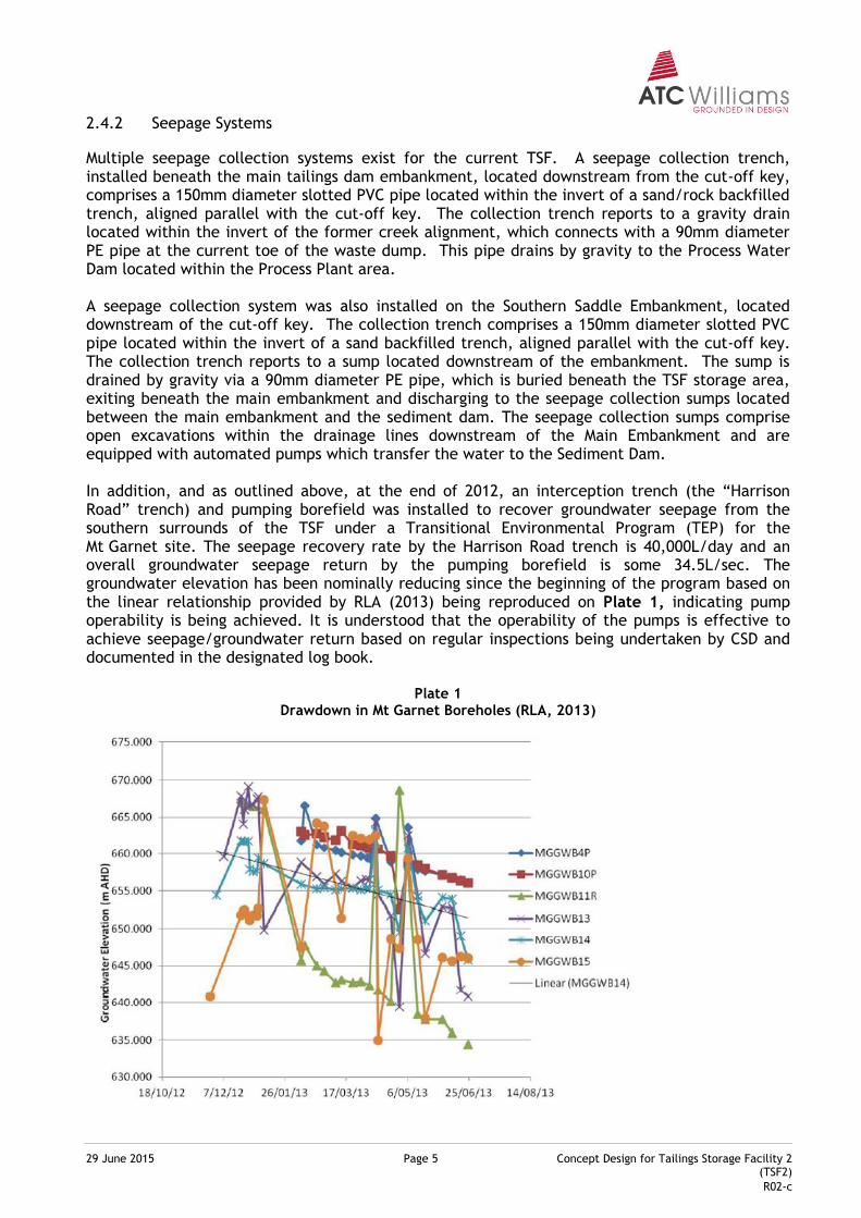
Multiple seepage collection systems exist for the current TSF. A seepage collection trench, installed beneath the main tailings dam embankment, located downstream from the cut-off key, comprises a 150mm diameter slotted PVC pipe located within the invert of a sand/rock backfilled trench, aligned parallel with the cut-off key. The collection trench reports to a gravity drain located within the invert of the former creek alignment, which connects with a 90mm diameter PE pipe at the current toe of the waste dump. This pipe drains by gravity to the Process Water Dam located within the Process Plant area. A seepage collection system was also installed on the Southern Saddle Embankment, located downstream of the cut-off key. The collection trench comprises a 150mm diameter slotted PVC pipe located within the invert of a sand backfilled trench, aligned parallel with the cut-off key. The collection trench reports to a sump located downstream of the embankment. The sump is drained by gravity via a 90mm diameter PE pipe, which is buried beneath the TSF storage area, exiting beneath the main embankment and discharging to the seepage collection sumps located between the main embankment and the sediment dam. The seepage collection sumps comprise open excavations within the drainage lines downstream of the Main Embankment and are equipped with automated pumps which transfer the water to the Sediment Dam. In addition, and as outlined above, at the end of 2012, an interception trench (the “Harrison Road” trench) and pumping borefield was installed to recover groundwater seepage from the southern surrounds of the TSF under a Transitional Environmental Program (TEP) for the Mt Garnet site. The seepage recovery rate by the Harrison Road trench is 40,000L/day and an overall groundwater seepage return by the pumping borefield is some 34.5L/sec. The groundwater elevation has been nominally reducing since the beginning of the program based on the linear relationship provided by RLA (2013) being reproduced on Plate 1, indicating pump operability is being achieved. It is understood that the operability of the pumps is effective to achieve seepage/groundwater return based on regular inspections being undertaken by CSD and documented in the designated log book.
Plate 1 Drawdown in Mt Garnet Boreholes (RLA, 2013)
29 June 2015 Page 6 Concept Design for Tailings Storage Facility 2 (TSF2)
R02-c
2.4.3 Tailings Development
Tailings deposition occurs from spigotted peripheral discharge pipelines, which facilitate subaerial deposition of tailings within the storage. The method of deposition is by discharge via PVC pipe lengths to the tailings beach surface. The characteristics of the tailings is as follows:
Classification Sandy SILT (RLA, 2012)
Colour Grey (RLA, 2012)
Hydraulic Conductivity 1 x 10⁻⁷ m/sec (RLA, 2012)
Specific Gravity 3.1 to 3.2 t/m3
Slurry Solids Concentration 30%
Beach Dry Density 1.7 t/m3
Beach Slope 2% (average) Based on the provided tailings characteristics, it is considered that the development concepts for the TSF development, to be reflected on the TSF2 concept are appropriate.
2.4.4 Emergency Spillway
The Emergency Spillway for the TSF is located on the south western abutment of the main tailings dam embankment. The spillway is excavated into competent natural sequences.

29 June 2015 Page 7 Concept Design for Tailings Storage Facility 2 (TSF2)
R02-c
3 DESIGN BACKGROUND DATA
3.1 Site Conditions and Associated Design Implications
3.1.1 Site Topographic and Hydrology
The Mt Garnet Project is located south of the Mount Garnet township. The region comprises hilly terrain with numerous rocky outcrops and predominant land uses include cattle grazing and mining. The project area is situated within a sub-catchment of the Herbert River, which discharges to the Coral Sea. Within the site area, the ephemeral drainage system flows into the main site drainage channel named Return (Nanyeta) Creek which flows in a south-easterly direction to Herbert River (Plate 2). The site catchment is significantly disturbed, due to previous mining activity and the surface is described as generally rocky. Vegetation in undisturbed areas consists of woodland to open forest.
Plate 2 Drainage Systems and Surrounding Environment near Mt Garnet
3.1.2 Climate Conditions
The climate of the Mt Garnet region is described as dry tropical, with distinct wet and dry seasons. The average annual rainfall in the region is approximately 830 mm.1 The distribution of this rainfall, in terms of monthly average totals (records commenced 1901) is shown in Plate 2.
1 Bureau of Meteorology for Station No. 031046, Mount Garnet Post Office.
29 June 2015 Page 8 Concept Design for Tailings Storage Facility 2 (TSF2)
R02-c
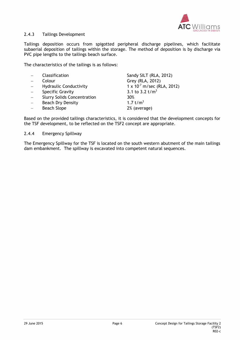
Rainfall is greatest during the summer months December to March, with the highest monthly average rainfall total of 200 mm in February. The driest month is September with an average rainfall of 7 mm. Long-term evaporation data for the Mt Garnet region is not available, however evaporation has been recorded at Walkamin Research Station, approximately 70 km north-east of Mt Garnet. The average total annual evaporation for this site is 1,820 mm.2 On an average monthly basis, highest evaporation occurs between October and January. During dry season months, evaporation is significantly lower, with the lowest average monthly total occurring during June.
Plate 3 Mt Garnet Average Monthly Rainfall and Evaporation
3.1.3 Site Geology
Mt Garnet is located in the southern portion of the Siluro-Devonian Hodgkinson Province, dominated by sedimentary sequences which reduce in age towards the east into basalt flows and tuffaceous volcanic sequences. The Siluro-Devonian sequence sits non-conformably on the Precambrian metamorphics which are in turn non-conformably overlain by middle to upper Carboniferous sequences, locally referred to as the Nanyeta Volcanic Synchronous with deposition of these volcanics, granitoids such as the Elizabeth Creek Granite intruded the sequence, accompanied by the formation of hydrothermal base metal and tin-tungsten mineralisation. An erosional cycle has predominated since the Permian with the deposition of perched sediments and extrusion of olivine basalts in the Tertiary and early Quaternary. The valley in which the tailings dam, waste rock dump and dam are sited comprises Paleozoic sediments comprising medium to coarse grained moderately to thickly bedded arkose. Occasional finer grained, micaceous sediments are intercalated within the arkose. Within the floor of the valley, the arkose is overlain by a layer of up to 6.0m thick of alluvial/colluvial clays.
2 Bureau of Meteorology for Station No. 031108, Walkamin Research Station.
Jan Feb Mar Apr May Jun Jul Aug Sep Oct Nov Dec
Rainfall 181.1 200.3 136.2 42.2 23 20.6 11.8 8.4 7 20.8 59.6 119.7
Evaporation 170.5 138.43 145.7 129 117.8 105 114.7 136.4 171 201.5 198 192.2
0
50
100
150
200
250
Mo
nth
ly D
epth
(m
m)
29 June 2015 Page 9 Concept Design for Tailings Storage Facility 2 (TSF2)
R02-c
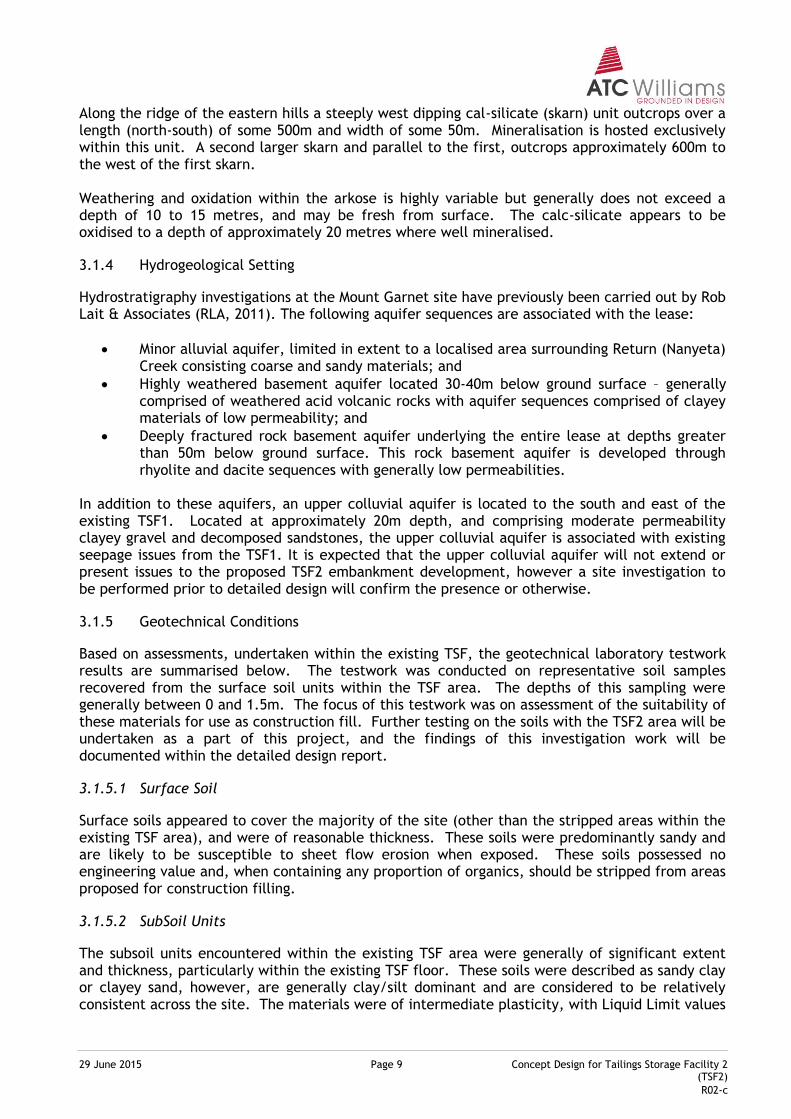
Along the ridge of the eastern hills a steeply west dipping cal-silicate (skarn) unit outcrops over a length (north-south) of some 500m and width of some 50m. Mineralisation is hosted exclusively within this unit. A second larger skarn and parallel to the first, outcrops approximately 600m to the west of the first skarn. Weathering and oxidation within the arkose is highly variable but generally does not exceed a depth of 10 to 15 metres, and may be fresh from surface. The calc-silicate appears to be oxidised to a depth of approximately 20 metres where well mineralised.
3.1.4 Hydrogeological Setting
Hydrostratigraphy investigations at the Mount Garnet site have previously been carried out by Rob Lait & Associates (RLA, 2011). The following aquifer sequences are associated with the lease:
Minor alluvial aquifer, limited in extent to a localised area surrounding Return (Nanyeta) Creek consisting coarse and sandy materials; and
Highly weathered basement aquifer located 30-40m below ground surface – generally comprised of weathered acid volcanic rocks with aquifer sequences comprised of clayey materials of low permeability; and
Deeply fractured rock basement aquifer underlying the entire lease at depths greater than 50m below ground surface. This rock basement aquifer is developed through rhyolite and dacite sequences with generally low permeabilities.
In addition to these aquifers, an upper colluvial aquifer is located to the south and east of the existing TSF1. Located at approximately 20m depth, and comprising moderate permeability clayey gravel and decomposed sandstones, the upper colluvial aquifer is associated with existing seepage issues from the TSF1. It is expected that the upper colluvial aquifer will not extend or present issues to the proposed TSF2 embankment development, however a site investigation to be performed prior to detailed design will confirm the presence or otherwise.
3.1.5 Geotechnical Conditions
Based on assessments, undertaken within the existing TSF, the geotechnical laboratory testwork results are summarised below. The testwork was conducted on representative soil samples recovered from the surface soil units within the TSF area. The depths of this sampling were generally between 0 and 1.5m. The focus of this testwork was on assessment of the suitability of these materials for use as construction fill. Further testing on the soils with the TSF2 area will be undertaken as a part of this project, and the findings of this investigation work will be documented within the detailed design report.
3.1.5.1 Surface Soil
Surface soils appeared to cover the majority of the site (other than the stripped areas within the existing TSF area), and were of reasonable thickness. These soils were predominantly sandy and are likely to be susceptible to sheet flow erosion when exposed. These soils possessed no engineering value and, when containing any proportion of organics, should be stripped from areas proposed for construction filling.
3.1.5.2 SubSoil Units
The subsoil units encountered within the existing TSF area were generally of significant extent and thickness, particularly within the existing TSF floor. These soils were described as sandy clay or clayey sand, however, are generally clay/silt dominant and are considered to be relatively consistent across the site. The materials were of intermediate plasticity, with Liquid Limit values
29 June 2015 Page 10 Concept Design for Tailings Storage Facility 2 (TSF2)
R02-c
ranging from 28% to 40%, and were generally classified as CI in accordance with the Unified Soil Classification System. Permeability achieved for the soils, tested under both field and laboratory conditions, are low to very low, falling within the range of 10-8 to 10-9 m/s. These subsoil unit materials were considered suitable for use as low permeability fill for embankment construction. The Emerson Class number achieved for a number of samples, however, indicates some potential for dispersion/erosion. Placement and compaction of these materials should be carefully controlled, as a result, to reduce the potential for internal erosion or piping to occur, and to achieve appropriately low levels of permeability.
3.1.5.3 Basement Unit
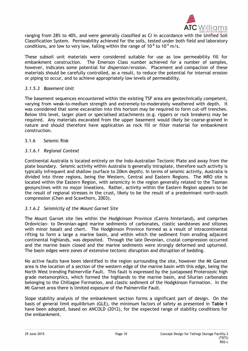
The basement sequences encountered within the existing TSF area are geotechnically competent, varying from weak-to-medium strength and extremely-to-moderately weathered with depth. It was considered that some excavation into this horizon may be required to form cut-off trenches. Below this level, larger plant or specialised attachments (e.g. rippers or rock breakers) may be required. Any materials excavated from the upper basement would likely be coarse-grained in nature and should therefore have application as rock fill or filter material for embankment construction.
3.1.6 Seismic Risk
3.1.6.1 Regional Context
Continental Australia is located entirely on the Indo-Australian Tectonic Plate and away from the plate boundary. Seismic activity within Australia is generally intraplate, therefore such activity is typically infrequent and shallow (surface to 20km depth). In terms of seismic activity, Australia is divided into three regions, being the Western, Central and Eastern Regions. The MRO site is located within the Eastern Region, with seismicity in the region generally related to the Tasman geosynclines with no major lineations. Rather, activity within the Eastern Region appears to be the result of regional stresses in the crust, likely to be the result of a predominant north-south compression (Chen and Scawthorn, 2003).
3.1.6.2 Seismicity of the Mount Garnet Site
The Mount Garnet site lies within the Hodgkinson Province (Cairns hinterland), and comprises Ordovician- to Devonian-aged marine sediments of carbonates, clastic sandstones and siltones with minor basalt and chert. The Hodgkinson Province formed as a result of intracontinental rifting to form a large a marine basin, and within which the sediment from eroding adjacent continental highlands, was deposited. Through the late Devonian, crustal compression occurred and the marine basin closed and the marine sediments were strongly deformed and upturned. The basin edges were zones of extensive tectonic disruption and disruption of bedding. No active faults have been identified in the region surrounding the site, however the Mt Garnet area is the location of a section of the western edge of the marine basin with this edge, being the North West trending Palmerville Fault. This fault is expressed by the juxtaposed Proterozoic high grade metamorphics, which formed the highlands to the marine basin, and Silurian carbonates belonging to the Chillagoe Formation, and clastic sediment of the Hodgkinson Formation. In the Mt Garnet area there is limited exposure of the Palmerville Fault. Slope stability analysis of the embankment section forms a significant part of design. On the basis of general limit equilibrium (GLE), the minimum factors of safety as presented in Table 1 have been adopted, based on ANCOLD (2012), for the expected range of stability conditions for the embankment.
29 June 2015 Page 11 Concept Design for Tailings Storage Facility 2 (TSF2)
R02-c
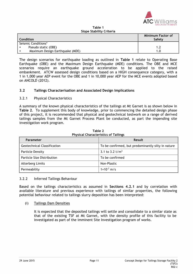
Table 1 Slope Stability Criteria
Condition Minimum Factor of
Safety
Seismic Conditions* Pseudo static (OBE) Maximum Design Earthquake (MDE)
1.2 1.0
The design scenarios for earthquake loading as outlined in Table 1 relate to Operating Base Earthquake (OBE) and the Maximum Design Earthquake (MDE) conditions. The OBE and MCE scenarios require an earthquake ground acceleration to be applied to the raised embankment. ATCW assessed design conditions based on a HIGH consequence category, with a 1 in 1,000 year AEP event for the OBE and 1 in 10,000 year AEP for the MCE events adopted based on ANCOLD (2012).
3.2 Tailings Characterisation and Associated Design Implications
3.2.1 Physical Characteristics
A summary of the known physical characteristics of the tailings at Mt Garnet is as shown below in Table 2. To supplement this body of knowledge, prior to commencing the detailed design phase of this project, it is recommended that physical and geotechnical testwork on a range of derived tailings samples from the Mt Garnet Process Plant be conducted, as part the impending site investigation work program.
Table 2 Physical Characteristics of Tailings
Parameter Result
Geotechnical Classification To be confirmed, but predominantly silty in nature
Particle Density 3.1 to 3.2 t/m3
Particle Size Distribution To be confirmed
Atterberg Limits Non-Plastic
Permeability 1×10⁻⁷ m/s
3.2.2 Inferred Tailings Behaviour
Based on the tailings characteristics as assumed in Sections 4.2.1 and by correlation with available literature and previous experience with tailings of similar properties, the following potential behaviour related to tailings slurry deposition has been interpreted:
(i) Tailings Dam Densities It is expected that the deposited tailings will settle and consolidate to a similar state as that of the existing TSF at Mt Garnet, with the density profile of this facility to be investigated as part of the imminent Site Investigation program of works.
29 June 2015 Page 12 Concept Design for Tailings Storage Facility 2 (TSF2)
R02-c
(ii) Tailings Water Recoveries
Based on the assumed densities and taking into account losses of water to evaporation, seepage and storage within the tailings mass, a conservative (lower bound) rate of tailings water recovery of some 30 per cent of the total tailings water input is likely to apply. It is acknowledged, that the water recovery potential can be affected by the quantity of rainfall at Mt Garnet, as well as the relative areas of exposed tailings beach/decant pond and the condition of the beach on which the tailings are discharged.
(iii) Beach Slopes
Beach slopes expected to be achieved, subject to sub-aerial deposition methods, would be of the order of 0.5% to 1.0%, with steeper slopes closer to the discharge points and the beach generally forming a slightly concave beach shape representing a segregating beach deposition regime consistent with the operating slurry densities achieved.
(iv) Tailings Permeability
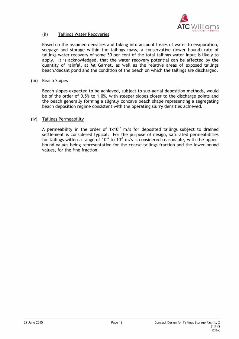
A permeability in the order of 1x10⁻⁷ m/s for deposited tailings subject to drained settlement is considered typical. For the purpose of design, saturated permeabilities for tailings within a range of 10-6 to 10-8 m/s is considered reasonable, with the upper-bound values being representative for the coarse tailings fraction and the lower-bound values, for the fine fraction.
29 June 2015 Page 13 Concept Design for Tailings Storage Facility 2 (TSF2)
R02-c
4 CRITERIA FOR TSF DEVELOPMENT
4.1 Philosophy
The general design philosophy with respect to TSF development is as follows:
(i) Provide for the efficient storage of tailings, forming an operational and post-closure landform that is geotechnically competent/stable and not subject to excessive or uncontrolled emissions to the environment; and
(ii) Provide an integral component of the total site water management system, such that releases from the system to the environment are eliminated for all but extreme conditions.
The general operational philosophy for the TSF is based on the use of subaerial techniques for tailings deposition. Such techniques involve discharge of tailings from multiple locations on the perimeter of the tailings storage area. At each discharge location, the tailings slurry produces near laminar flow over the gently sloping tailings beach to enable segregation and deposition of tailings solids. Subsequent evaporation from the exposed beach surface consolidates the tailings as a means of increasing in situ deposited densities and shear strengths. Water liberated from the tailings through the deposition phase accumulates within a water pond at the toe of the beach. From this pond, water can be decanted and is available for reuse.
4.1.1 Consequence Assessment Basis and Context
Dams and related land-based containment structures associated with environmentally relevant activities (ERA’s) under the Environmental Protection Act (referred to as regulated dams) are subject to an assessment of consequence category. The consequence assessment for dams and containment structures is based on three scenarios, as follows:
(i) “Failure to Contain” scenarios - Spills or releases from the dam; (ii) “Dam Break” scenarios - Collapse of the dam structure; (iii) “Dam Seepage” scenarios - Seepage through the dam embankments/ foundation.
Based on the site conditions and setting, as outlined in Section 2, the aspects relevant to consequence assessment for the proposed TSF are described below.
4.1.2 Consequence Assessment
The proposed TSF has been classified as being of “HIGH” consequence in accordance with DEHP (2013), with the qualitative assessment presented in the sections below. The classification of the proposed TSF is made with regard to the permanent containment of tailings and contaminants generated by site operations. Under each of the scenarios presented in Section 4.1.1, several modes of failure are possible, with each failure mode needing to be considered separately. The scenarios and failure modes are discussed in greater detail in the sections that follow. A Failure to Contain scenario is defined as any spills or releases from the structure that result from loss of containment due to overtopping of the structure. Although failure to contain scenarios are typically non-flood producing, it is acknowledged that a Failure to Contain scenario may involve the release of contaminants, which could potentially endanger environmental values or human life.
29 June 2015 Page 14 Concept Design for Tailings Storage Facility 2 (TSF2)
R02-c
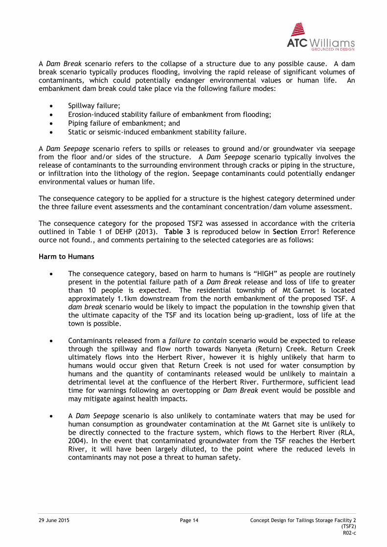
A Dam Break scenario refers to the collapse of a structure due to any possible cause. A dam break scenario typically produces flooding, involving the rapid release of significant volumes of contaminants, which could potentially endanger environmental values or human life. An embankment dam break could take place via the following failure modes:
Spillway failure;
Erosion-induced stability failure of embankment from flooding;
Piping failure of embankment; and
Static or seismic-induced embankment stability failure. A Dam Seepage scenario refers to spills or releases to ground and/or groundwater via seepage from the floor and/or sides of the structure. A Dam Seepage scenario typically involves the release of contaminants to the surrounding environment through cracks or piping in the structure, or infiltration into the lithology of the region. Seepage contaminants could potentially endanger environmental values or human life. The consequence category to be applied for a structure is the highest category determined under the three failure event assessments and the contaminant concentration/dam volume assessment. The consequence category for the proposed TSF2 was assessed in accordance with the criteria outlined in Table 1 of DEHP (2013). Table 3 is reproduced below in Section Error! Reference ource not found., and comments pertaining to the selected categories are as follows: Harm to Humans
The consequence category, based on harm to humans is “HIGH” as people are routinely present in the potential failure path of a Dam Break release and loss of life to greater than 10 people is expected. The residential township of Mt Garnet is located approximately 1.1km downstream from the north embankment of the proposed TSF. A dam break scenario would be likely to impact the population in the township given that the ultimate capacity of the TSF and its location being up-gradient, loss of life at the town is possible.
Contaminants released from a failure to contain scenario would be expected to release through the spillway and flow north towards Nanyeta (Return) Creek. Return Creek ultimately flows into the Herbert River, however it is highly unlikely that harm to humans would occur given that Return Creek is not used for water consumption by humans and the quantity of contaminants released would be unlikely to maintain a detrimental level at the confluence of the Herbert River. Furthermore, sufficient lead time for warnings following an overtopping or Dam Break event would be possible and may mitigate against health impacts.
A Dam Seepage scenario is also unlikely to contaminate waters that may be used for human consumption as groundwater contamination at the Mt Garnet site is unlikely to be directly connected to the fracture system, which flows to the Herbert River (RLA, 2004). In the event that contaminated groundwater from the TSF reaches the Herbert River, it will have been largely diluted, to the point where the reduced levels in contaminants may not pose a threat to human safety.
29 June 2015 Page 15 Concept Design for Tailings Storage Facility 2 (TSF2)
R02-c
Harm to Environment
The consequence category, based on general environmental harm would be “HIGH” as potential significant and permanent adverse effects and damage would be expected. The most catastrophic failure impact pathway, which would exist in the event of overtopping or a dam break event, would extending northwest approximately 750m downstream towards Return Creek. Adverse effects would be expected along Return Creek with the extents of the impact likely to exceed 5km2. A large and rapid release of contaminants from a "Dam Break" scenario would be expected to significantly and permanently alter the surrounding ecosystem, with remedial works expected to be costly.
A release of contaminants from a failure to contain scenario would likely migrate downstream to Return Creek and be expected to affect slightly to moderately disturbed waters with the downstream area of influence being greater than 1km2.
A dam seepage scenario would be unlikely to significantly and permanently alter the environment as alluvial sequences in the area are restricted laterally by less permeable bedrock and hence, only have a limited groundwater storage capacity (RLA, 2004).
General Economic Loss
The consequence category, based on general economic loss or property damage would be “SIGNIFICANT” as the third party assets in the form of urban development at Mt Garnet township would potentially be impacted. The township resides 1.1km from the northern TSF embankment with damage predominantly extending to drainage works, roads and other utilities, rather than town infrastructure. The quantity of contaminants released by a dam break scenario may be significant enough to affect areas beyond the downstream plant site area and cause long term damage to residential houses within the Mt Garnet township. Compensation, remedial and rehabilitation works, as a result of a dam break scenario would be expected to cost $1 million or greater, but less than $10 million by way of rehabilitation, compensation, repair or rectification costs.
A release of contaminants from a failure to contain scenario would be unlikely to reach the Mt Garnet Township as the quantity of contaminants released in such an event would likely be influenced to flow downstream to Return Creek. It is likely that contaminants migrating towards the town would be contained within the plant site area given the volumes likely to be released in a failure to contain scenario. Any adverse impacts to third party assets would be likely to incur a remedial and compensation cost of less than $1 million.
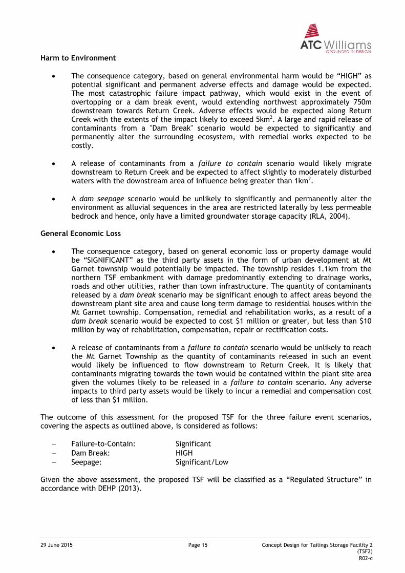
The outcome of this assessment for the proposed TSF for the three failure event scenarios, covering the aspects as outlined above, is considered as follows:
Failure-to-Contain: Significant
Dam Break: HIGH
Seepage: Significant/Low Given the above assessment, the proposed TSF will be classified as a “Regulated Structure” in accordance with DEHP (2013).
29 June 2015 Page 16 Concept Design for Tailings Storage Facility 2 (TSF2)
R02-c
4.2 Design Criteria
4.2.1 Tailings Storage Capacity (Process Inputs)
CSD defined an overall containment capacity of approximately 1.92 M.m3 of tailings. This storage will provide approximately eight years of capacity.
4.2.2 Hydrology and Hydraulics
(i) Stormwater Containment Capacity Criteria for storage/containment for the TSF are assessed based on DEHP (2013), which defines storage capacity required for a process tailings dam, as the Design Storage Allowance (DSA). The DSA is calculated as the excess storage volume occurring at 1 November of each year that will be filled by runoff from the nominated design critical wet period as well as the process inputs for the critical wet period. Based on the consequence assessment for the TSF (Section 3.1.2) and site locality the storage allowance will be based on a 1 in 100 year critical duration (3-month) wet season.
(ii) Emergency Spillway Design
The emergency spillway for the TSF throughout the development is to be designed in accordance DEHP (2013) and ANCOLD (2000). The minimum criterion is for the spillway to achieve capacity as follows:
Consequence Category Spillway Capacity Flood Level for embankment crest levels
Containment dams high consequence
1:1,000 AEP to 1:100,000 AEP Spillway design flood peak level + wave run-up allowance for 1:10 AEP wind
4.2.3 Embankment Stability
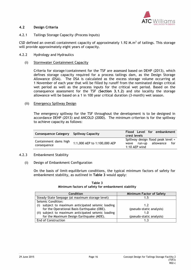
(i) Design of Embankment Configuration On the basis of limit-equilibrium conditions, the typical minimum factors of safety for embankment stability, as outlined in Table 3 would apply:
Table 3
Minimum factors of safety for embankment stability
Condition Minimum Factor of Safety
Steady-State Seepage (at maximum storage level) 1.5
Seismic Condition: (i) subject to maximum anticipated seismic loading
for the Operational Basis Earthquake (OBE). (ii) subject to maximum anticipated seismic loading
for the Maximum Design Earthquake (MDE).
1.2 (pseudo-static analysis)
1.0 (pseudo-static analysis)
End of Construction 1.3
29 June 2015 Page 17 Concept Design for Tailings Storage Facility 2 (TSF2)
R02-c
(ii) Embankment Serviceability The embankment serviceability criteria subject to flooding conditions includes the external embankment batter surfaces require armouring to at least a 1 in 500 year flood level in order to provide the required stability against potential erosion. In terms of seepage management, no quantifiable criteria would generally apply, other than inference against the following: (i) excessive surface expression of seepage discharge downstream from the
embankment should not occur; (ii) a significant impact on the environmental status of receiving waters should not
result from the TSF; and (iii) the potential beneficial uses of surface and groundwater down gradient from the
site should not be compromised. Notwithstanding, there is a requirement to minimise seepage from the TSF into adjacent drainage lines.
4.2.4 Construction Materials
The embankment construction materials would be sourced locally (i.e. within close proximity to the TSF), with the quarrying of a spur within the TSF2 storage extents to provide the construction fill source for rock fill materials. Target properties of the materials used in TSF construction, based on past experience and performance assessment are likely to include the following:
(i) Earth/Clay Fill (for use as containment zone)
Clay dominant material (clay/silt fraction greater than 20% and Liquid Limits ranging from 25% to 60%);
Undrained shear strength in excess of 50kPa after compaction;
Achievable compacted permeability of less than 10-8 m/s; and
“Engineerable” to reduce potential “internal” erosion/piping. The key to the above suite of properties is to create a fill layer that possesses high strength, compacts well, is stable (i.e. not subject to significant vertical settlement under load or volume instability due to variation in moisture content) and importantly, provides an appropriately low level of permeability.
(ii) Rock Fill (for use as embankment fill)
The purpose of rock fill within an embankment would be to enhance structural stability as well as to provide erosion protection to external portions of the embankment. General requirements for rock fill would be as follows:
High load bearing capacity;
Stable and durable (with respect to potential settlement, volume instability, erosion potential and weathering);
High permeability relative to adjacent embankment or subgrade zones; and
Geochemically stable (i.e. non-acid producing).
29 June 2015 Page 18 Concept Design for Tailings Storage Facility 2 (TSF2)
R02-c
4.3 Operational Criteria
4.3.1 Decant/Return Water Quality
Appropriate practices with respect to maintaining the quality of decant/return water (to be reused within the process) are to be adopted. As a minimum, provisions to be made to limit the significant alteration of decant water quality within the TSF will include:
(i) Maintaining a sufficiently large enough decant pond to enable sufficient residence time for settlement of suspended solids prior to recovery; and
(ii) Maintaining an appropriate tailings deposition regime (in terms of cycling periods) such that the tailings beach consolidation is maximised, thereby maximising tailings storage efficiency.
4.3.2 Seepage Management
Appropriate practices to manage the rate or quality of seepage water that may be released from the system are to be adopted. As a minimum, provisions to be made to manage seepage migration effects shall include:
(i) Maintaining an appropriate tailings deposition regime (in terms of cycling periods) to maximise consolidation of the tailings and water recovery;
(ii) Whilst maximising water recovery, as outlined above, the volumes of free water occurring within the decant pond should be limited. This outcome requires an effective balance between deposition scheduling and decant water recovery rate;
(iii) Implementation of effective, staged rehabilitation works to minimise the potential seepage footprint.
(iv) Monitoring of surface water and groundwater quality around the TSF to detect excessive seepage migration, and implement mitigation works as deemed necessary.
29 June 2015 Page 19 Concept Design for Tailings Storage Facility 2 (TSF2)
R02-c
5 TSF2 DEVELOPMENT CONCEPT
5.1 Development Concept
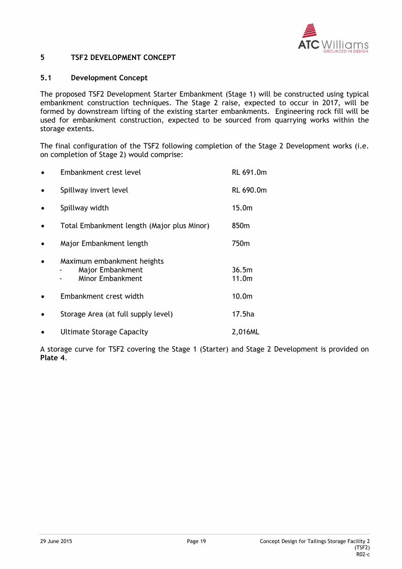
The proposed TSF2 Development Starter Embankment (Stage 1) will be constructed using typical embankment construction techniques. The Stage 2 raise, expected to occur in 2017, will be formed by downstream lifting of the existing starter embankments. Engineering rock fill will be used for embankment construction, expected to be sourced from quarrying works within the storage extents. The final configuration of the TSF2 following completion of the Stage 2 Development works (i.e. on completion of Stage 2) would comprise:
Embankment crest level RL 691.0m
Spillway invert level RL 690.0m
Spillway width 15.0m
Total Embankment length (Major plus Minor) 850m
Major Embankment length 750m
Maximum embankment heights - Major Embankment 36.5m - Minor Embankment 11.0m
Embankment crest width 10.0m
Storage Area (at full supply level) 17.5ha
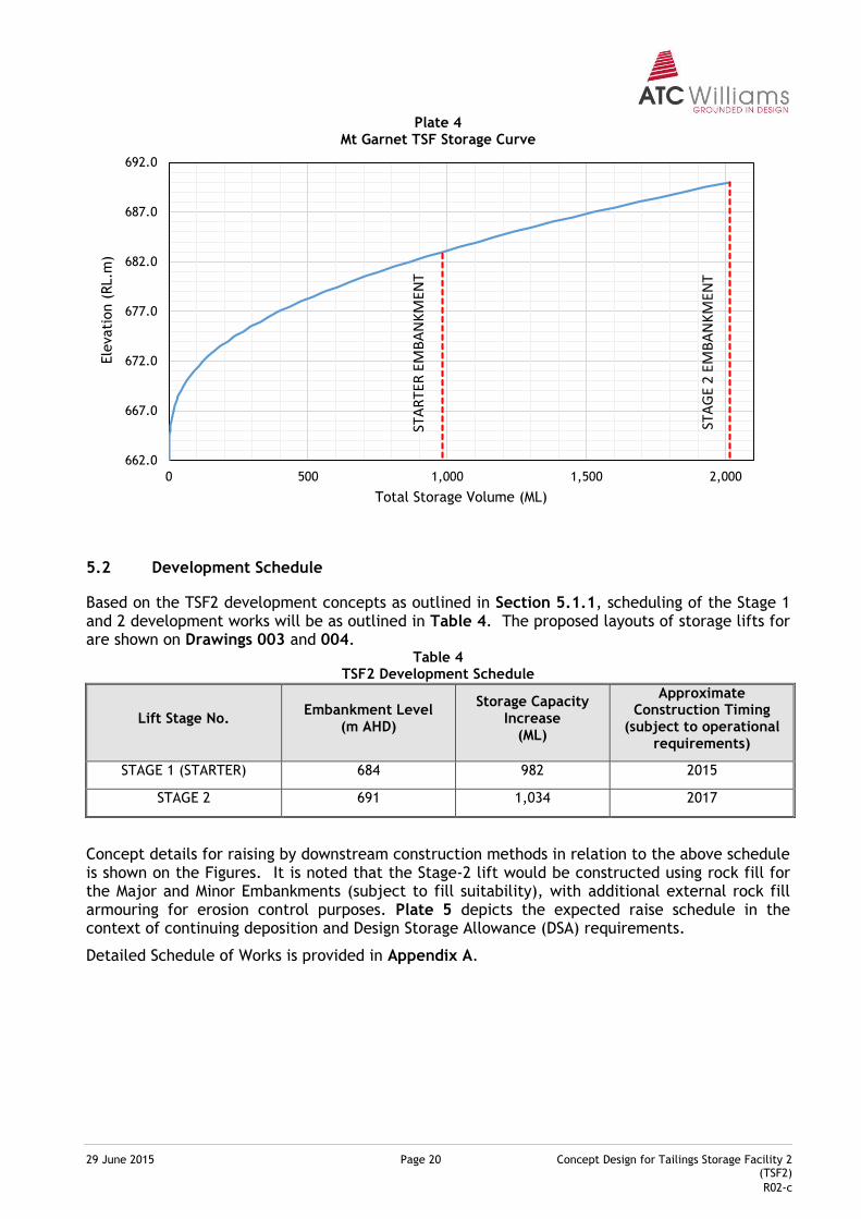
Ultimate Storage Capacity 2,016ML A storage curve for TSF2 covering the Stage 1 (Starter) and Stage 2 Development is provided on Plate 4.
29 June 2015 Page 20 Concept Design for Tailings Storage Facility 2 (TSF2)
R02-c
Plate 4 Mt Garnet TSF Storage Curve
5.2 Development Schedule
Based on the TSF2 development concepts as outlined in Section 5.1.1, scheduling of the Stage 1 and 2 development works will be as outlined in Table 4. The proposed layouts of storage lifts for are shown on Drawings 003 and 004.
Table 4 TSF2 Development Schedule
Lift Stage No. Embankment Level
(m AHD)
Storage Capacity Increase
(ML)
Approximate Construction Timing
(subject to operational requirements)
STAGE 1 (STARTER) 684 982 2015
STAGE 2 691 1,034 2017
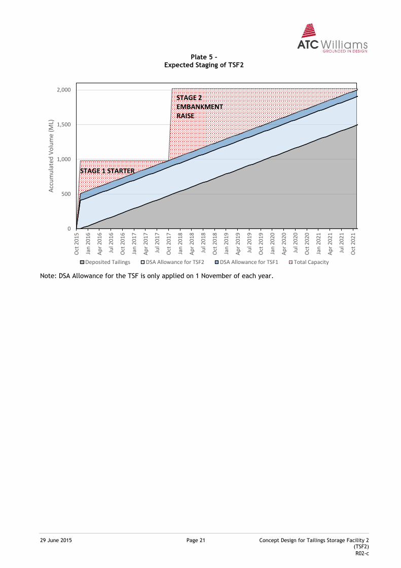
Concept details for raising by downstream construction methods in relation to the above schedule is shown on the Figures. It is noted that the Stage-2 lift would be constructed using rock fill for the Major and Minor Embankments (subject to fill suitability), with additional external rock fill armouring for erosion control purposes. Plate 5 depicts the expected raise schedule in the context of continuing deposition and Design Storage Allowance (DSA) requirements.
Detailed Schedule of Works is provided in Appendix A.
662.0
667.0
672.0
677.0
682.0
687.0
692.0
0 500 1,000 1,500 2,000
Ele
vati
on (
RL.m
)
Total Storage Volume (ML)
STA
RTE
REM
BA
NK
MEN
T
STA
GE
2 E
MB
AN
KM
ENT
29 June 2015 Page 21 Concept Design for Tailings Storage Facility 2 (TSF2)
R02-c
Plate 5 – Expected Staging of TSF2
Note: DSA Allowance for the TSF is only applied on 1 November of each year.
0
500
1,000
1,500
2,000
Oct
20
15
Jan
20
16
Ap
r 2
01
6
Jul 2
01
6
Oct
20
16
Jan
20
17
Ap
r 2
01
7
Jul 2
01
7
Oct
20
17
Jan
20
18
Ap
r 2
01
8
Jul 2
01
8
Oct
20
18
Jan
20
19
Ap
r 2
01
9
Jul 2
01
9
Oct
20
19
Jan
20
20
Ap
r 2
02
0
Jul 2
02
0
Oct
20
20
Jan
20
21
Ap
r 2
02
1
Jul 2
02
1
Oct
20
21
Acc
um
ula
ted
Vo
lum
e (M
L)
Deposited Tailings DSA Allowance for TSF2 DSA Allowance for TSF1 Total Capacity
STAGE 1 STARTER
STAGE 2 EMBANKMENT RAISE
29 June 2015 Page 22 Concept Design for Tailings Storage Facility 2 (TSF2)
R02-c
6 ENGINEERING ANALYSES
6.1 TSF2 Water Management
CSD water management strategy intent in relation to the proposed TSF2 development is summarised as follows:
Clean Water Management
Clean water associated with the TSF2 comprises storm water runoff occurring outside the limits of the TSF2, which is able to be diverted away from TSF2. A Clean water diversion drain is to be located along the eastern margin of TSF2. Discharge from this drain is directed into the Return (Nanyeta) Creek catchment to the west of the site.
Tailings Water Management
The limits of the TSF2 catchment are defined by the storage embankments, and the clean water diversion to the south. The total diverted catchment area of the tailings dam (i.e. the area reporting to the TSF assuming diversions operational) is some 20.4ha.
Water occurring within the TSF2 is derived from the following sources:
o direct rainfall over the tailings surface and decant pond; o storm water runoff from the surrounding catchment; and o water liberated from deposited tailings. The recovery of water from the decant pond is expected to occur via a sled mounted recovery pump. Decant water will be returned to the Process Dam within the plant area. The decant pump is to be operated remotely from the plant control room and operated to minimize the ponded volume within the decant pond. Previous site water management has included the use of enhanced evaporators from the Pit development and from the existing TSF decant. Site intent is to not utilise enhanced evaporation in the normal operation of the TSF2 decant pond, however the measure remains a contingent option for extreme rainfall conditions.
6.2 Storage Freeboard and Design Storage Allowance
For regulated structures, a minimum available storage capacity, referred to as Design Storage Allowance (DSA) is defined. This capacity is therefore a constraint applying to the operating phase of the structure (in this case the West Dam). DSA is determined based on the Manual for Assessing Consequence Categories and Hydraulic Performance of Structures (DEHP, 2013) using the Method of Deciles, with the DSA representing the storage required as at 1 November of each year that will be filled by stormwater runoff from a defined critical wet period plus the expected process inputs from the critical wet period. As outlined in Section 3.3.2, the performance criteria applying to TSF2 and existing TSF, as a reflection of anticipated EA requirements, are shown in Table 5.
29 June 2015 Page 23 Concept Design for Tailings Storage Facility 2 (TSF2)
R02-c
Table 5
TSF Performance Criteria
Method of Analysis Consequence Category
HIGH
Method of Deciles
- Critical Wet Period 3 months
- Design event probability (AEP) 1 in 100 years (0.01 AEP)
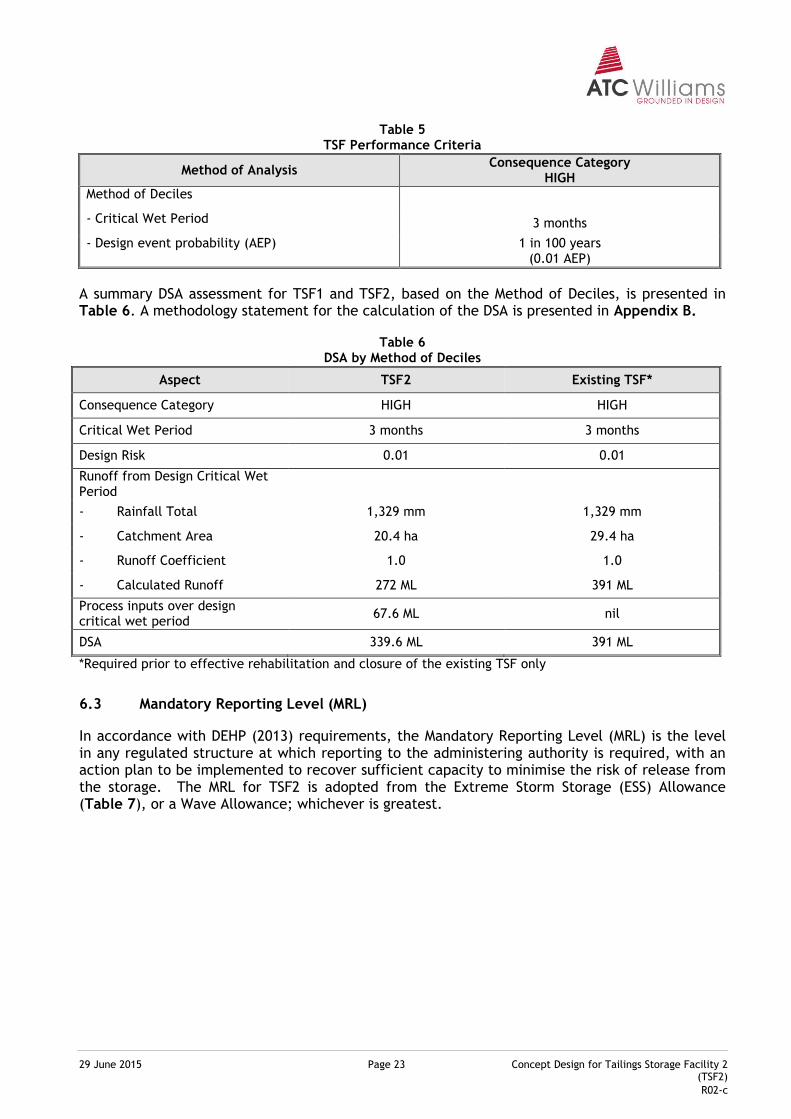
A summary DSA assessment for TSF1 and TSF2, based on the Method of Deciles, is presented in Table 6. A methodology statement for the calculation of the DSA is presented in Appendix B.
Table 6 DSA by Method of Deciles
Aspect TSF2 Existing TSF*
Consequence Category HIGH HIGH
Critical Wet Period 3 months 3 months
Design Risk 0.01 0.01
Runoff from Design Critical Wet Period
- Rainfall Total 1,329 mm 1,329 mm
- Catchment Area 20.4 ha 29.4 ha
- Runoff Coefficient 1.0 1.0
- Calculated Runoff 272 ML 391 ML
Process inputs over design critical wet period
67.6 ML nil
DSA 339.6 ML 391 ML
*Required prior to effective rehabilitation and closure of the existing TSF only
6.3 Mandatory Reporting Level (MRL)
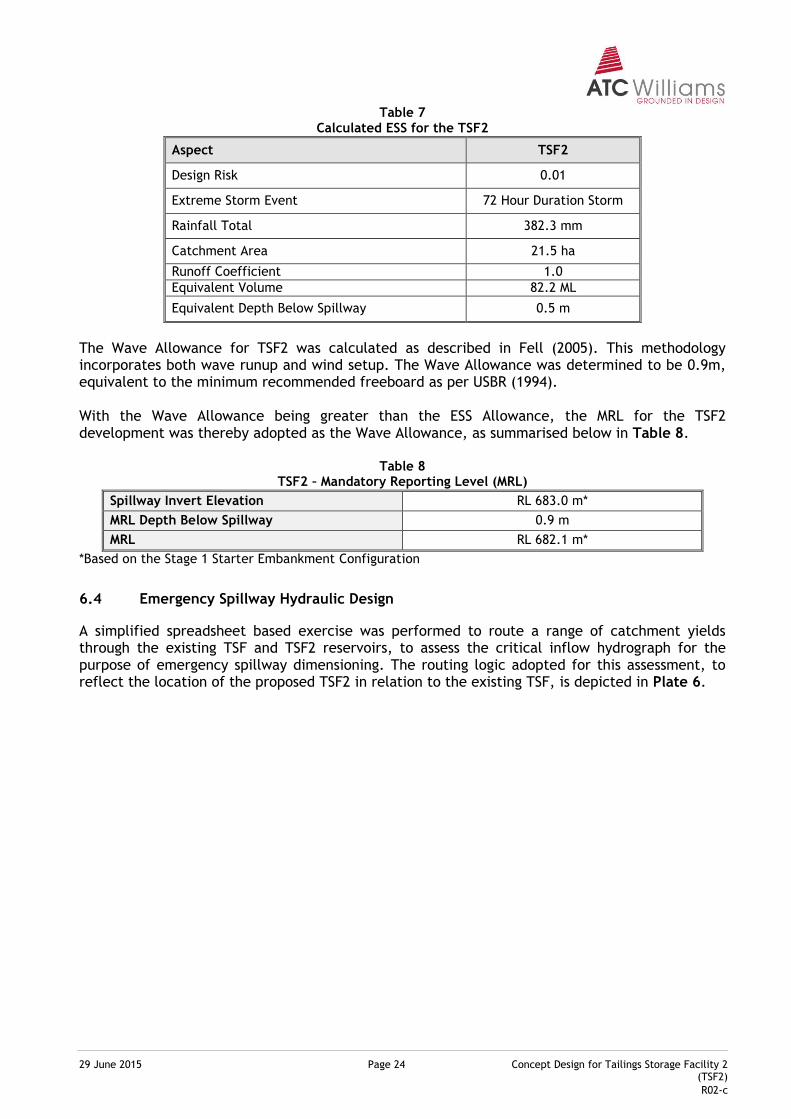
In accordance with DEHP (2013) requirements, the Mandatory Reporting Level (MRL) is the level in any regulated structure at which reporting to the administering authority is required, with an action plan to be implemented to recover sufficient capacity to minimise the risk of release from the storage. The MRL for TSF2 is adopted from the Extreme Storm Storage (ESS) Allowance (Table 7), or a Wave Allowance; whichever is greatest.
29 June 2015 Page 24 Concept Design for Tailings Storage Facility 2 (TSF2)
R02-c
Table 7 Calculated ESS for the TSF2
Aspect TSF2
Design Risk 0.01
Extreme Storm Event 72 Hour Duration Storm
Rainfall Total 382.3 mm
Catchment Area 21.5 ha
Runoff Coefficient 1.0
Equivalent Volume 82.2 ML
Equivalent Depth Below Spillway 0.5 m
The Wave Allowance for TSF2 was calculated as described in Fell (2005). This methodology incorporates both wave runup and wind setup. The Wave Allowance was determined to be 0.9m, equivalent to the minimum recommended freeboard as per USBR (1994). With the Wave Allowance being greater than the ESS Allowance, the MRL for the TSF2 development was thereby adopted as the Wave Allowance, as summarised below in Table 8.
Table 8 TSF2 – Mandatory Reporting Level (MRL)
Spillway Invert Elevation RL 683.0 m*
MRL Depth Below Spillway 0.9 m
MRL RL 682.1 m*
*Based on the Stage 1 Starter Embankment Configuration
6.4 Emergency Spillway Hydraulic Design
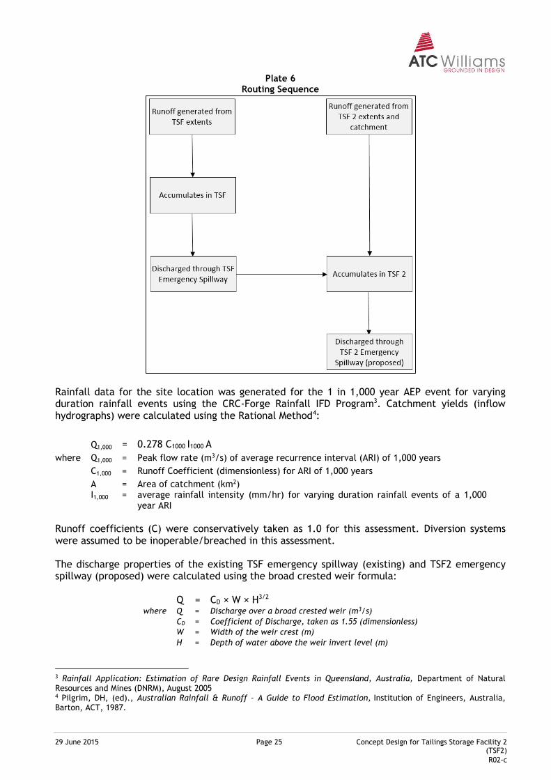
A simplified spreadsheet based exercise was performed to route a range of catchment yields through the existing TSF and TSF2 reservoirs, to assess the critical inflow hydrograph for the purpose of emergency spillway dimensioning. The routing logic adopted for this assessment, to reflect the location of the proposed TSF2 in relation to the existing TSF, is depicted in Plate 6.
29 June 2015 Page 25 Concept Design for Tailings Storage Facility 2 (TSF2)
R02-c
Plate 6 Routing Sequence
Rainfall data for the site location was generated for the 1 in 1,000 year AEP event for varying duration rainfall events using the CRC-Forge Rainfall IFD Program3. Catchment yields (inflow hydrographs) were calculated using the Rational Method4:
Q1,000 = 0.278 C1000 I1000 A
where Q1,000 = Peak flow rate (m3/s) of average recurrence interval (ARI) of 1,000 years
C1,000 = Runoff Coefficient (dimensionless) for ARI of 1,000 years
A = Area of catchment (km2)
I1,000
=
average rainfall intensity (mm/hr) for varying duration rainfall events of a 1,000 year ARI
Runoff coefficients (C) were conservatively taken as 1.0 for this assessment. Diversion systems were assumed to be inoperable/breached in this assessment. The discharge properties of the existing TSF emergency spillway (existing) and TSF2 emergency spillway (proposed) were calculated using the broad crested weir formula:
Q = CD × W × H3/2 where Q = Discharge over a broad crested weir (m3/s)
CD = Coefficient of Discharge, taken as 1.55 (dimensionless)
W = Width of the weir crest (m)
H = Depth of water above the weir invert level (m)
3 Rainfall Application: Estimation of Rare Design Rainfall Events in Queensland, Australia, Department of Natural Resources and Mines (DNRM), August 2005 4 Pilgrim, DH, (ed)., Australian Rainfall & Runoff – A Guide to Flood Estimation, Institution of Engineers, Australia, Barton, ACT, 1987.
29 June 2015 Page 26 Concept Design for Tailings Storage Facility 2 (TSF2)
R02-c
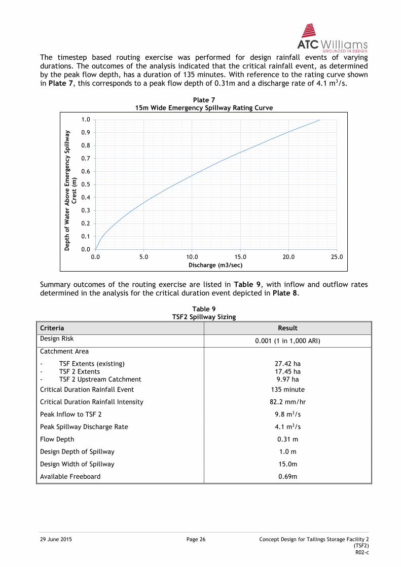
The timestep based routing exercise was performed for design rainfall events of varying durations. The outcomes of the analysis indicated that the critical rainfall event, as determined by the peak flow depth, has a duration of 135 minutes. With reference to the rating curve shown in Plate 7, this corresponds to a peak flow depth of 0.31m and a discharge rate of 4.1 m3/s.
Plate 7 15m Wide Emergency Spillway Rating Curve
Summary outcomes of the routing exercise are listed in Table 9, with inflow and outflow rates determined in the analysis for the critical duration event depicted in Plate 8.
Table 9 TSF2 Spillway Sizing
Criteria Result
Design Risk 0.001 (1 in 1,000 ARI)
Catchment Area
- TSF Extents (existing) - TSF 2 Extents - TSF 2 Upstream Catchment
27.42 ha 17.45 ha 9.97 ha
Critical Duration Rainfall Event 135 minute
Critical Duration Rainfall Intensity 82.2 mm/hr
Peak Inflow to TSF 2 9.8 m3/s
Peak Spillway Discharge Rate 4.1 m3/s
Flow Depth 0.31 m
Design Depth of Spillway 1.0 m
Design Width of Spillway 15.0m
Available Freeboard 0.69m
0.0
0.1
0.2
0.3
0.4
0.5
0.6
0.7
0.8
0.9
1.0
0.0 5.0 10.0 15.0 20.0 25.0
Depth
of
Wate
r A
bove E
merg
ency S
pillw
ay
Cre
st (
m)
Discharge (m3/sec)
29 June 2015 Page 27 Concept Design for Tailings Storage Facility 2 (TSF2)
R02-c
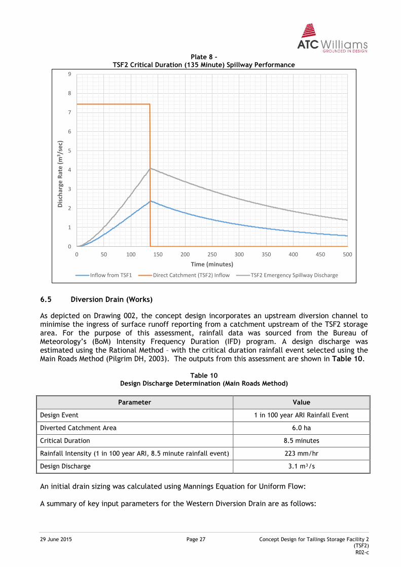
Plate 8 – TSF2 Critical Duration (135 Minute) Spillway Performance
6.5 Diversion Drain (Works)
As depicted on Drawing 002, the concept design incorporates an upstream diversion channel to minimise the ingress of surface runoff reporting from a catchment upstream of the TSF2 storage area. For the purpose of this assessment, rainfall data was sourced from the Bureau of Meteorology’s (BoM) Intensity Frequency Duration (IFD) program. A design discharge was estimated using the Rational Method – with the critical duration rainfall event selected using the Main Roads Method (Pilgrim DH, 2003). The outputs from this assessment are shown in Table 10.
Table 10 Design Discharge Determination (Main Roads Method)
Parameter Value
Design Event 1 in 100 year ARI Rainfall Event
Diverted Catchment Area 6.0 ha
Critical Duration 8.5 minutes
Rainfall Intensity (1 in 100 year ARI, 8.5 minute rainfall event) 223 mm/hr
Design Discharge 3.1 m³/s
An initial drain sizing was calculated using Mannings Equation for Uniform Flow: A summary of key input parameters for the Western Diversion Drain are as follows:
0
1
2
3
4
5
6
7
8
9
0 50 100 150 200 250 300 350 400 450 500
Dis
char
ge R
ate
(m
3 /se
c)
Time (minutes)
Inflow from TSF1 Direct Catchment (TSF2) Inflow TSF2 Emergency Spillway Discharge
29 June 2015 Page 28 Concept Design for Tailings Storage Facility 2 (TSF2)
R02-c
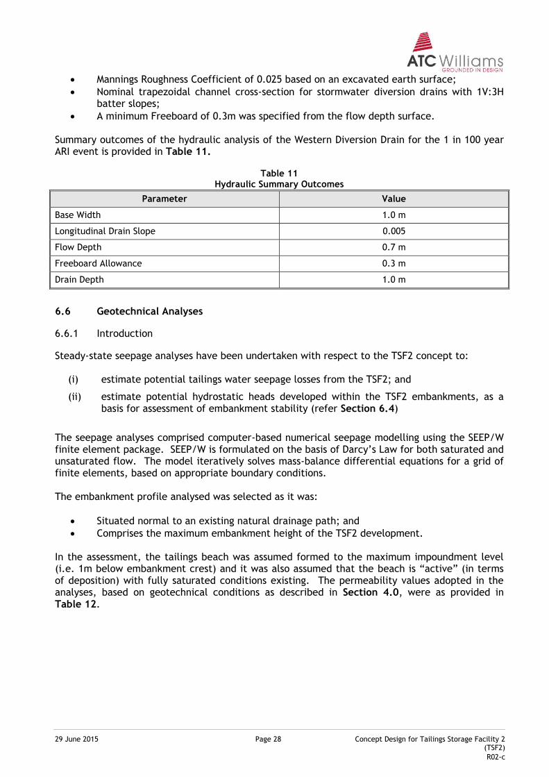
Mannings Roughness Coefficient of 0.025 based on an excavated earth surface;
Nominal trapezoidal channel cross-section for stormwater diversion drains with 1V:3H batter slopes;
A minimum Freeboard of 0.3m was specified from the flow depth surface. Summary outcomes of the hydraulic analysis of the Western Diversion Drain for the 1 in 100 year ARI event is provided in Table 11.
Table 11
Hydraulic Summary Outcomes
Parameter Value
Base Width 1.0 m
Longitudinal Drain Slope 0.005
Flow Depth 0.7 m
Freeboard Allowance 0.3 m
Drain Depth 1.0 m
6.6 Geotechnical Analyses
6.6.1 Introduction
Steady-state seepage analyses have been undertaken with respect to the TSF2 concept to:
(i) estimate potential tailings water seepage losses from the TSF2; and
(ii) estimate potential hydrostatic heads developed within the TSF2 embankments, as a basis for assessment of embankment stability (refer Section 6.4)
The seepage analyses comprised computer-based numerical seepage modelling using the SEEP/W finite element package. SEEP/W is formulated on the basis of Darcy’s Law for both saturated and unsaturated flow. The model iteratively solves mass-balance differential equations for a grid of finite elements, based on appropriate boundary conditions. The embankment profile analysed was selected as it was:
Situated normal to an existing natural drainage path; and
Comprises the maximum embankment height of the TSF2 development. In the assessment, the tailings beach was assumed formed to the maximum impoundment level (i.e. 1m below embankment crest) and it was also assumed that the beach is “active” (in terms of deposition) with fully saturated conditions existing. The permeability values adopted in the analyses, based on geotechnical conditions as described in Section 4.0, were as provided in Table 12.
29 June 2015 Page 29 Concept Design for Tailings Storage Facility 2 (TSF2)
R02-c
Table 12 Permeability Values Adopted in Seepage Analyses
Zone Description Adopted Saturated Permeability (m/s)
Insitu Materials
Residual Profile 1×10⁻⁹
Basement Sequence 1×10⁻⁹
Engineered/Tailings Materials
Rock Fill 1×10⁻⁶
Clay Barrier Layer 1×10⁻¹⁰
Deposited Tailings 1×10⁻⁷
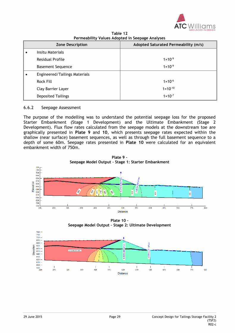
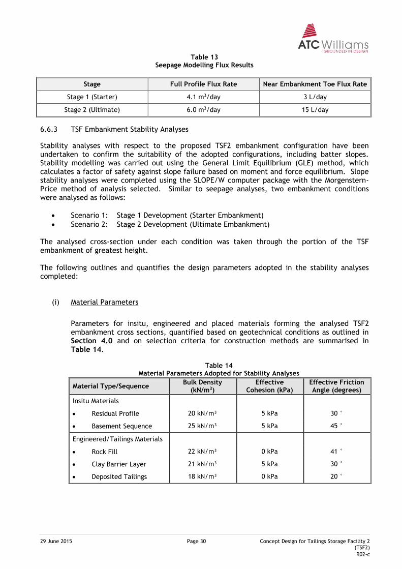
6.6.2 Seepage Assessment
The purpose of the modelling was to understand the potential seepage loss for the proposed Starter Embankment (Stage 1 Development) and the Ultimate Embankment (Stage 2 Development). Flux flow rates calculated from the seepage models at the downstream toe are graphically presented in Plate 9 and 10, which presents seepage rates expected within the shallow (near surface) basement sequences, as well as through the full basement sequence to a depth of some 60m. Seepage rates presented in Plate 10 were calculated for an equivalent embankment width of 750m.
Plate 9 – Seepage Model Output – Stage 1: Starter Embankment
Plate 10 – Seepage Model Output – Stage 2: Ultimate Development
29 June 2015 Page 30 Concept Design for Tailings Storage Facility 2 (TSF2)
R02-c
Table 13 Seepage Modelling Flux Results
Stage Full Profile Flux Rate Near Embankment Toe Flux Rate
Stage 1 (Starter) 4.1 m3/day 3 L/day
Stage 2 (Ultimate) 6.0 m3/day 15 L/day
6.6.3 TSF Embankment Stability Analyses
Stability analyses with respect to the proposed TSF2 embankment configuration have been undertaken to confirm the suitability of the adopted configurations, including batter slopes. Stability modelling was carried out using the General Limit Equilibrium (GLE) method, which calculates a factor of safety against slope failure based on moment and force equilibrium. Slope stability analyses were completed using the SLOPE/W computer package with the Morgenstern-Price method of analysis selected. Similar to seepage analyses, two embankment conditions were analysed as follows:
Scenario 1: Stage 1 Development (Starter Embankment)
Scenario 2: Stage 2 Development (Ultimate Embankment) The analysed cross-section under each condition was taken through the portion of the TSF embankment of greatest height. The following outlines and quantifies the design parameters adopted in the stability analyses completed:
(i) Material Parameters
Parameters for insitu, engineered and placed materials forming the analysed TSF2 embankment cross sections, quantified based on geotechnical conditions as outlined in Section 4.0 and on selection criteria for construction methods are summarised in Table 14.
Table 14
Material Parameters Adopted for Stability Analyses
Material Type/Sequence Bulk Density
(kN/m3) Effective
Cohesion (kPa) Effective Friction Angle (degrees)
Insitu Materials
Residual Profile 20 kN/m³ 5 kPa 30 °
Basement Sequence 25 kN/m³ 5 kPa 45 °
Engineered/Tailings Materials
Rock Fill 22 kN/m³ 0 kPa 41 °
Clay Barrier Layer 21 kN/m³ 5 kPa 30 °
Deposited Tailings 18 kN/m³ 0 kPa 20 °
29 June 2015 Page 31 Concept Design for Tailings Storage Facility 2 (TSF2)
R02-c
(ii) Hydrostatic Conditions within Embankment
Output from the steady-state seepage modelling for Scenario 1 and Scenario 2 provide profiles of the developed phreatic surface within the TSF2 embankment. The hydrostatic conditions represented by this phreatic surface profiles provide direct input the slope stability analyses, via coupled SEEP/SLOPE modelling.
(iii) Seismic Effects
The effects of seismic loading were also considered as part of the slope stability analysis. Based on Section 4.1.6, the estimated seismic coefficients for Maximum Credible Earthquake (MCE) and operating basis earthquake (OBE) were 0.2 and 0.072, respectively.
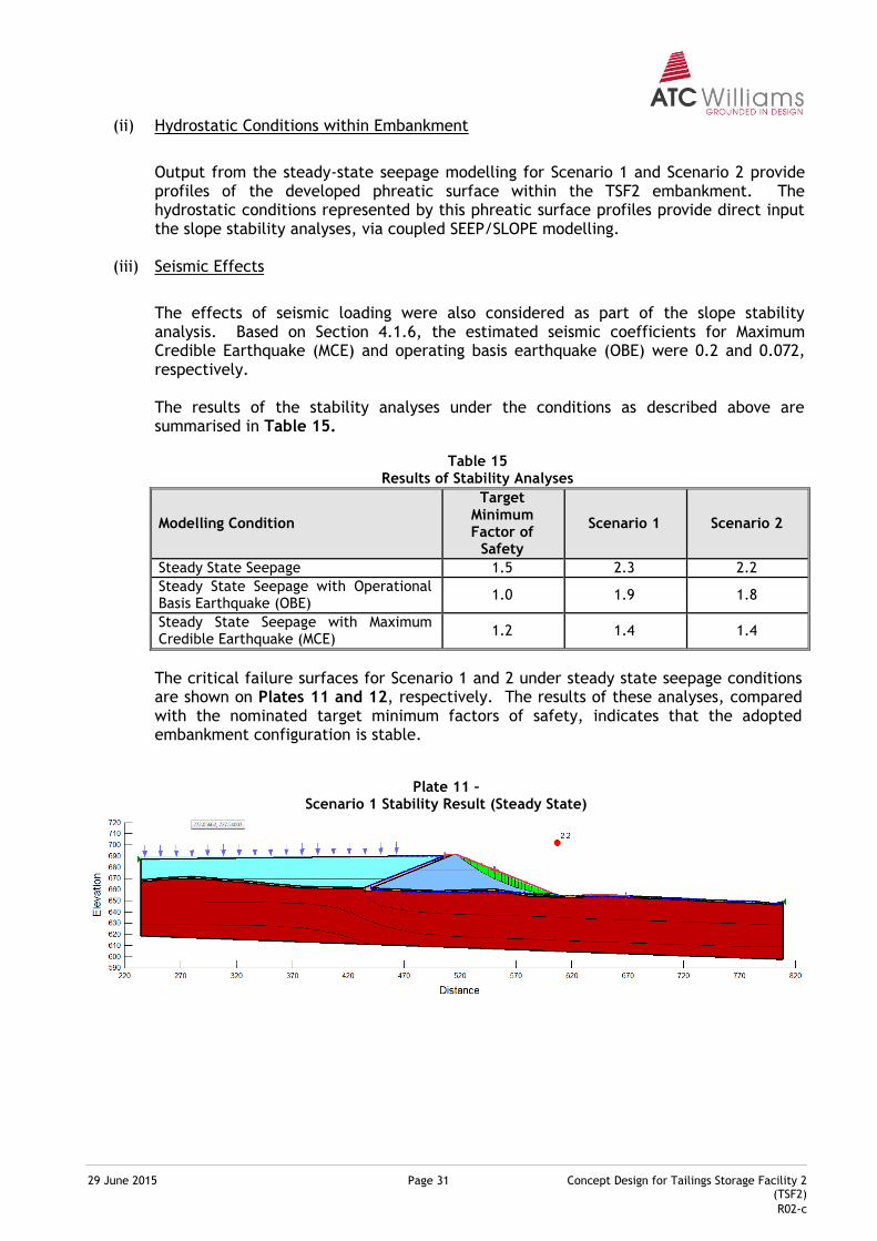
The results of the stability analyses under the conditions as described above are summarised in Table 15.
Table 15
Results of Stability Analyses
Modelling Condition
Target Minimum Factor of
Safety
Scenario 1 Scenario 2
Steady State Seepage 1.5 2.3 2.2
Steady State Seepage with Operational Basis Earthquake (OBE)
1.0 1.9 1.8
Steady State Seepage with Maximum Credible Earthquake (MCE)
1.2 1.4 1.4
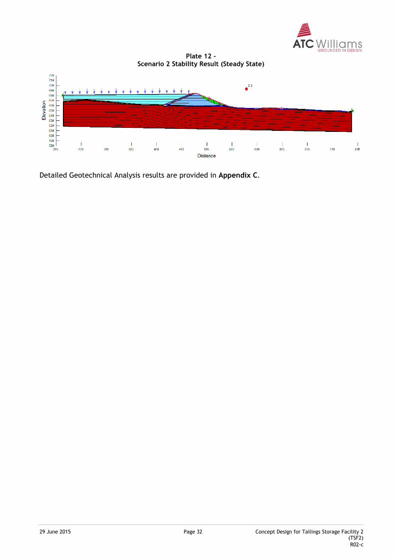
The critical failure surfaces for Scenario 1 and 2 under steady state seepage conditions are shown on Plates 11 and 12, respectively. The results of these analyses, compared with the nominated target minimum factors of safety, indicates that the adopted embankment configuration is stable.
Plate 11 – Scenario 1 Stability Result (Steady State)
29 June 2015 Page 32 Concept Design for Tailings Storage Facility 2 (TSF2)
R02-c
Plate 12 – Scenario 2 Stability Result (Steady State)
Detailed Geotechnical Analysis results are provided in Appendix C.
29 June 2015 Page 33 Concept Design for Tailings Storage Facility 2 (TSF2)
R02-c
7 OPERATIONAL AND CLOSURE ASPECTS
A number of operational and closure issues apply to the ultimate TSF2 to maintain consistency with the concept design philosophies adopted. These issues are outlined as follows:
7.1 Tailings Deposition Practices
As outlined in Section 3.0, the general design philosophy adopted for the TSF2 development is based on the use of sub-aerial techniques for tailings deposition. Such techniques involve discharge of tailings from multiple locations on the perimeter of the TSF2. Water liberated in conjunction with the deposition phase is recovered for return to the Process Plant. The significance of sub-aerial deposition techniques in the context of the proposed TSF2 development concept is such that:
tailings storage efficiencies are maximised;
a tailings surface is developed, possessing characteristics that may ultimately be suitable for external embankment upstream lift construction and final rehabilitation works;
tailings permeabilities are reduced, minimising the rate of seepage. Appropriate sequencing of tailings deposition is also suggested to ensure that over-drying of exposed tailings surface is avoided to minimise the potential for dusting of the tailings surface. A management process is therefore recommended, subject to dusting potential/issues, in relation to the TSF2 to avoid the implications of over-drying. Such a process may include periodic irrigation of the beach, primarily for disposal of excess water as a means of improving the site water balance (as required). Alternatively, application of an appropriate surface treatment to limit dusting may be implemented.
7.2 Tailings Water Management
Tailings water recovery from the TSF2 surface is integral to sub-aerial deposition techniques. During the operation of the system, transferring decant water from the TSF2 to the Process Plant (via the process pond) shall be a priority to minimise the risk of spill from the TSF2, recognising that a spill from the system should only occur in the event of an extreme rainfall period, and should cease generally within 24 hours of cessation of the event. It is also very important that during the course of TSF2 operation every effort should be made to avoid surcharging the system with excess water volumes from alternative sources.
7.3 Seepage Rate and Control
Conceptually, during the operation of the TSF2 and into the post closure phase, seepage from the storage would occur by development of a seepage plume, initially migrating slowly downwards into the foundation sequences. A local groundwater mound is expected to form beneath the storage, either directly connected with the underlying groundwater system, or perched above a horizon of lower permeability. This mound will eventually move hydraulically down-gradient, likely towards the north. As such, groundwater accumulation as a result of phreatic surcharge in the TSF2 is not expected to contribute to existing seepage issues from the existing TSF1, as a topographic divide separates the two groundwater drainage paths. The time taken for such seepage to migrate northwards
29 June 2015 Page 34 Concept Design for Tailings Storage Facility 2 (TSF2)
R02-c
would depend on the hydraulic capacity of the seepage pathways that may exist, either through the basement or beneath the cut-off key. It is likely that the rate of seepage from the storage would concentrate through the drainage line to the north-west of the storage. Evidence of seepage from the storage is likely to be observed as follows:
Expression of seepage at ground surface directly downstream from the embankment.
Depending on the continuity of surface soils, some seepage springs may appear in depressions/hollows or intersecting drainages further downstream. It is expected that seepage will impact the existing ‘Oasis’ and ‘Spring’ Dams, necessitating continued containment of water contained therein.
From the seepage analysis completed (refer Section 6.1), it appears that the most significant mechanism for seepage from the TSF2 to occur is through the embankment foundation units, or to a lesser extent, through the embankment. There are a number of feasible measures, focussing on these seepage mechanisms, which can reduce the magnitude of seepage from the proposed storage. Subsequent to the completion of a geotechnical site investigation, the following seepage control measures are to be assessed, refined and incorporated into the seepage model and reflected in the subsequent TSF2 detailed design:
A modified foundation cut-off key to intersect the basement sequences;
A low permeability embankment core zone;
Seepage recovery system.
The seepage rates currently estimated in the analysis, based on assumed control measures (recognising that these results are conservative based on the saturated conditions assumed), are of a magnitude that is considered manageable, and represent only a small proportion of the total water inputs to the tailings dam.
In addition to the proposed seepage control measures, monitoring and if necessary, subsequent implementation of additional seepage controls is a fundamental component of the TSF2 proposed development. Groundwater monitoring, particularly down-gradient from the TSF2 should be maintained. Where additional controls are considered necessary, such controls may comprise one or a combination of the following:
Installation of pumps in the groundwater monitoring bores, or construction of dedicated groundwater recovery wells;
Refinement of the water recovery practices adopted to reduce the volume of water retained within the system.
7.4 TSF Rehabilitation
The typical objectives to be adopted for rehabilitation of the TSF2 would be to create a landform that is:
(i) stable and sustainable; (ii) compatible with the surrounding landform; and (iii) of minimum long term environmental impact (i.e. non-polluting).
29 June 2015 Page 35 Concept Design for Tailings Storage Facility 2 (TSF2)
R02-c
Based on these objectives, a concept for the TSF2 development is as follows:
Landform Development
It is envisaged that the final TSF2 landform would comprise long-term stable external batters with an upper surface formed such that ponding is substantially avoided. This would therefore necessitate a final campaign of tailings deposition within the TSF2 to infill any significant depression. The formation of the final tailings beach is would occur prior to the surface rehabilitation of the TSF2 and subsequent performance monitoring achieving water quality objectives/criteria will be required. It is envisaged that this process would take several years following completion of deposition. Interim water management may comprise discharge into a downstream storage and or containment within the TSF2 extents.
Tailings Surface Capping
A tailings surface cap would serve the following purposes: (a) Facilitate ongoing surface water drainage and prevent ponding; (b) Stabilise the surface to mitigate against potential ongoing erosion; and (c) reduce potential rainfall infiltration into the tailings as recharge to seepage. To meet these performance standards, the cap would comprise the following components. This configuration assumes that the tailings would remain geochemically benign.
- Tailings Surface Stabilisation Layer (Capillary Break)
To provide a geotechnically competent surface over the surface of the tailings, a stabilisation layer may be necessary. The purpose of the stabilisation layer would be to provide a competent subgrade or bridging layer, which would limit the effective surcharge onto the tailings surface and thereby limit potential settlements. The area most likely to require stabilisation would be the decant pond surface, due to the likely extent of saturated slimes materials.
The stabilisation layer would typically comprise rock mattress (the rock comprising competent and durable material).
- Sealing Layer
A sealing layer would be required to reduce the downward infiltration of surface water, which would act as a recharge to seepage. The sealing layer would be constructed using a clay fill material, which would possess similar characteristics to the clay fill proposed for use in the embankment construction. The sealing layer would extend over the full surface area of the storage.
- Surface Protection Layer
To protect the tailings surface from erosion and exposure deterioration (through wetting and drying), a surface protection layer would be required. This layer could also be utilised as a rooting zone for vegetation depending on the proposed end land use.
29 June 2015 Page 36 Concept Design for Tailings Storage Facility 2 (TSF2)
R02-c
This layer would be formed typically using select run-of-mine waste rock from the open pit area. Geochemically, the waste should be non-acid producing. From a geotechnical perspective, the material should be non-erosive/dispersive. The thickness of this layer would be selected to not only maintain drainage, but also to compensate for settlement within the underlying tailings. A hummocky final land surface may also have some benefit with respect to maintaining moisture within the surface layers to support vegetation growth and to reduce erosion potential. The final surface landform would be subject to further, on-going assessment through the life of the facility.
A more detailed assessment of a suitable capping configuration would need to be completed, subject to more data being available with respect to the physical and geochemical characteristics of the tailings. In particular, geochemical compatibility between the tailings and capping materials must be confirmed to ensure the integrity of the capping horizon is not compromised.
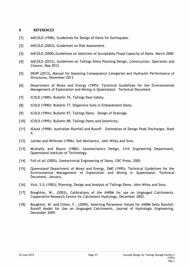
29 June 2015 Page 37
P R O P O S A L
Concept Design for Tailings Storage Facility 2 (TSF2)
R02-c
8 REFERENCES
[1] ANCOLD (1998), Guidelines for Design of Dams for Earthquake.
[2] ANCOLD (2003), Guidelines on Risk Assessment.
[3] ANCOLD (2000),Guidelines on Selection of Acceptable Flood Capacity of Dams, March 2000
[4] ANCOLD (2012), Guidelines on Tailings Dams Planning Design, Construction, Operation and Closure, May 2012
[5] DEHP (2013), Manual for Assessing Consequence Categories and Hydraulic Performance of Structures, November 2013
[6] Department of Mines and Energy (1995): Technical Guidelines for the Environmental Management of Exploration and Mining in Queensland. Technical Document.
[7] ICOLD (1989): Bulletin 74, Tailings Dam Safety.
[8] ICOLD (1990): Bulletin 77, Dispersive Soils in Embankment Dams.
[9] ICOLD (1994): Bulletin 97, Tailings Dams – Design of Drainage.
[10] ICOLD (1995): Bulletin 98, Tailings Dams and Seismicity.
[11] IEAust (1998): Australian Rainfall and Runoff – Estimation of Design Peak Discharges, Book 4.
[12] Lambe and Whitman (1996): Soil Mechanics, John Wiley and Sons.
[13] McAnally and Boyce (1980): Geomechanics Design, Civil Engineering Department, Queensland Institute of Technology.
[14] Fell et all (2005), Geotechnical Engineering of Dams, CRC Press, 2005
[15] Queensland Department of Mines and Energy, DME (1995); Technical Guidelines for the Environmental Management of Exploration and Mining in Queensland; Technical Document, January.
[16] Vick, S.G (1983); Planning, Design and Analysis of Tailings Dams, John Wiley and Sons.
[17] Boughton, W., (2003), Calibrations of the AWBM for use on Ungauged Catchments, Cooperative Research Centre for Catchment Hydrology, December 2003.
[18] Boughton, W. and Chiew, F., (2009), Selecting Parameter Values for AWBM Daily Rainfall-Runoff Model for Use on Ungauged Catchments, Journal of Hydrologic Engineering, December 2009.

P R O P O S A L
F I G U R E S
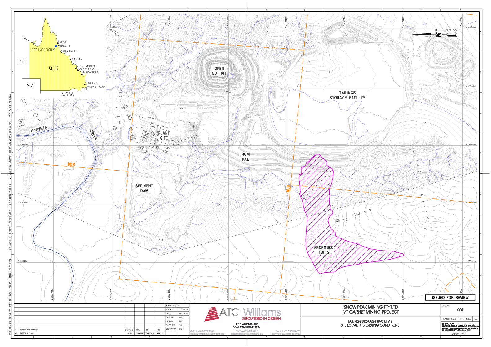
ISSUED FOR REVIEW
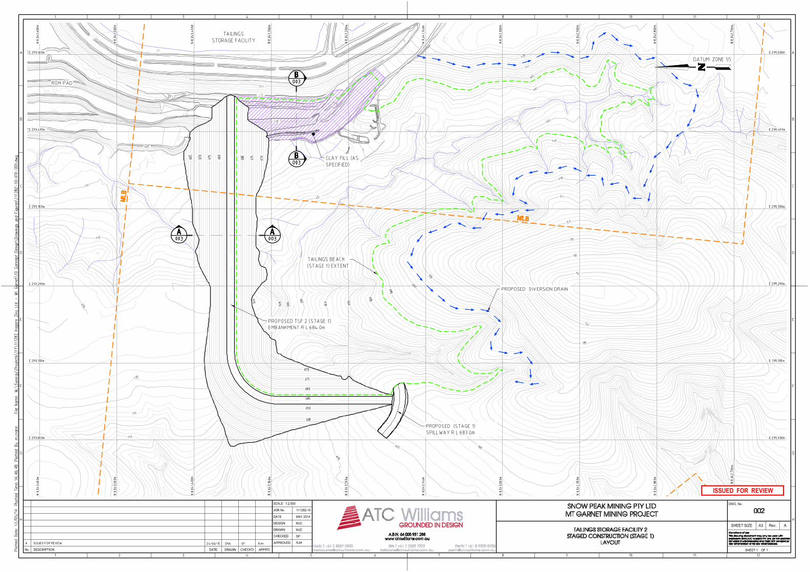
ISSUED FOR REVIEW
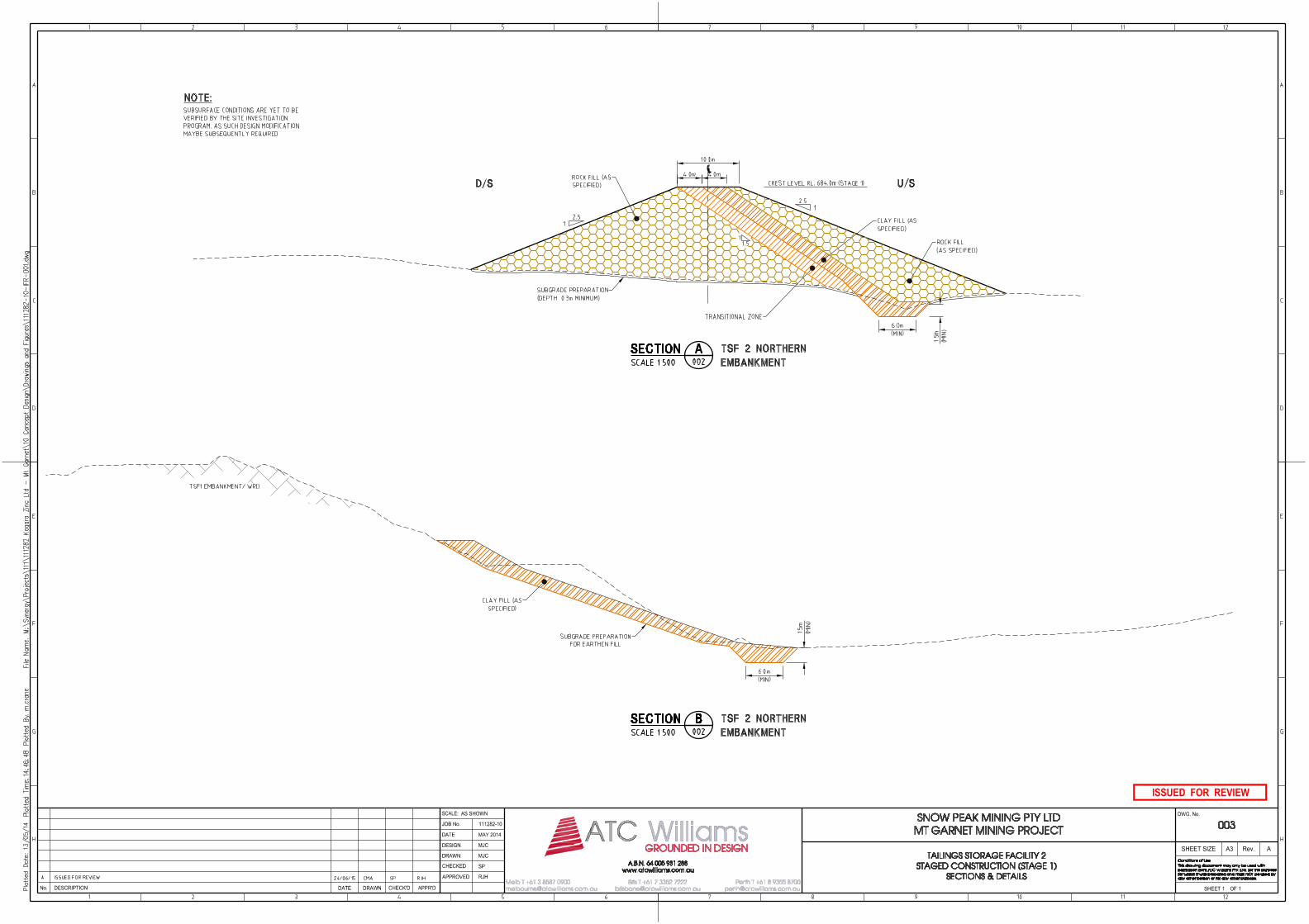
ISSUED FOR REVIEW
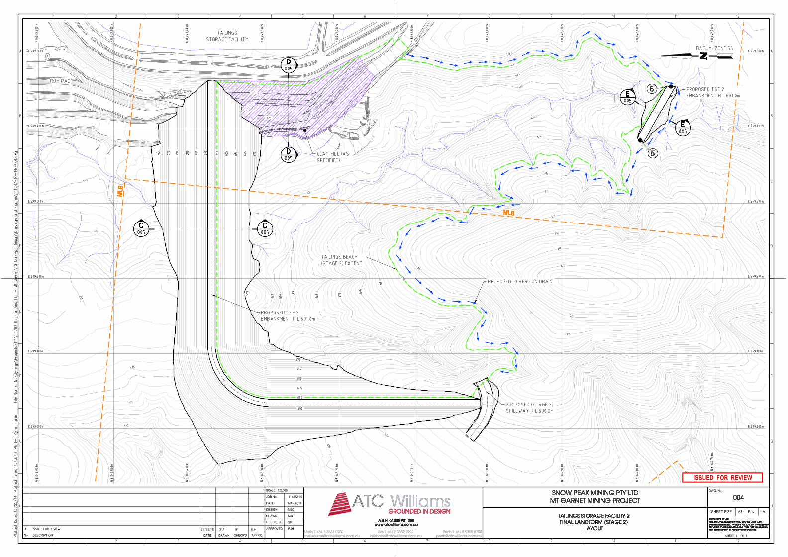
ISSUED FOR REVIEW
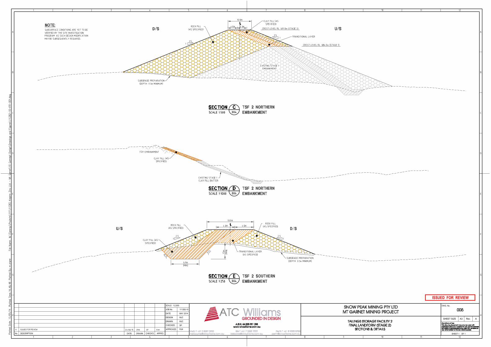
ISSUED FOR REVIEW

P R O P O S A L
A P P E N D I C E S

P R O P O S A L
A P P E N D I X A
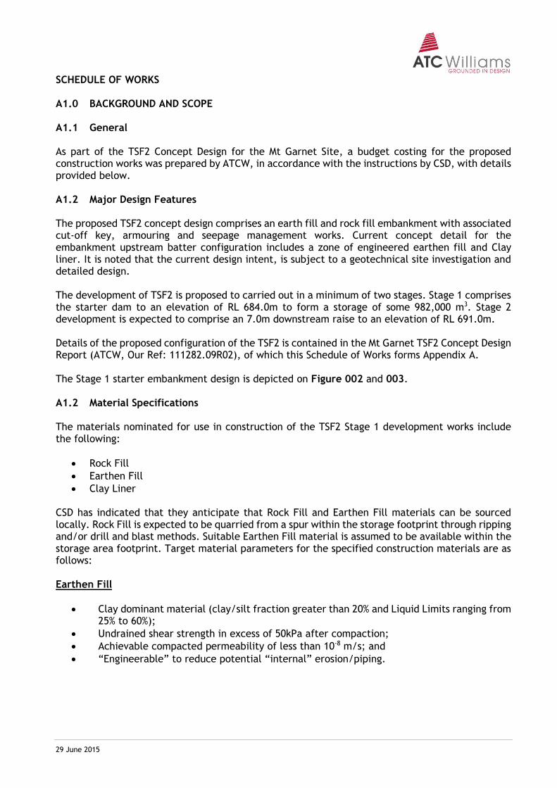
29 June 2015 Schedule of Works
SCHEDULE OF WORKS A1.0 BACKGROUND AND SCOPE A1.1 General As part of the TSF2 Concept Design for the Mt Garnet Site, a budget costing for the proposed construction works was prepared by ATCW, in accordance with the instructions by CSD, with details provided below. A1.2 Major Design Features The proposed TSF2 concept design comprises an earth fill and rock fill embankment with associated cut-off key, armouring and seepage management works. Current concept detail for the embankment upstream batter configuration includes a zone of engineered earthen fill and Clay liner. It is noted that the current design intent, is subject to a geotechnical site investigation and detailed design. The development of TSF2 is proposed to carried out in a minimum of two stages. Stage 1 comprises the starter dam to an elevation of RL 684.0m to form a storage of some 982,000 m3. Stage 2 development is expected to comprise an 7.0m downstream raise to an elevation of RL 691.0m. Details of the proposed configuration of the TSF2 is contained in the Mt Garnet TSF2 Concept Design Report (ATCW, Our Ref: 111282.09R02), of which this Schedule of Works forms Appendix A. The Stage 1 starter embankment design is depicted on Figure 002 and 003. A1.2 Material Specifications The materials nominated for use in construction of the TSF2 Stage 1 development works include the following:
Rock Fill
Earthen Fill
Clay Liner
CSD has indicated that they anticipate that Rock Fill and Earthen Fill materials can be sourced locally. Rock Fill is expected to be quarried from a spur within the storage footprint through ripping and/or drill and blast methods. Suitable Earthen Fill material is assumed to be available within the storage area footprint. Target material parameters for the specified construction materials are as follows: Earthen Fill
Clay dominant material (clay/silt fraction greater than 20% and Liquid Limits ranging from 25% to 60%);
Undrained shear strength in excess of 50kPa after compaction;
Achievable compacted permeability of less than 10-8 m/s; and
“Engineerable” to reduce potential “internal” erosion/piping.
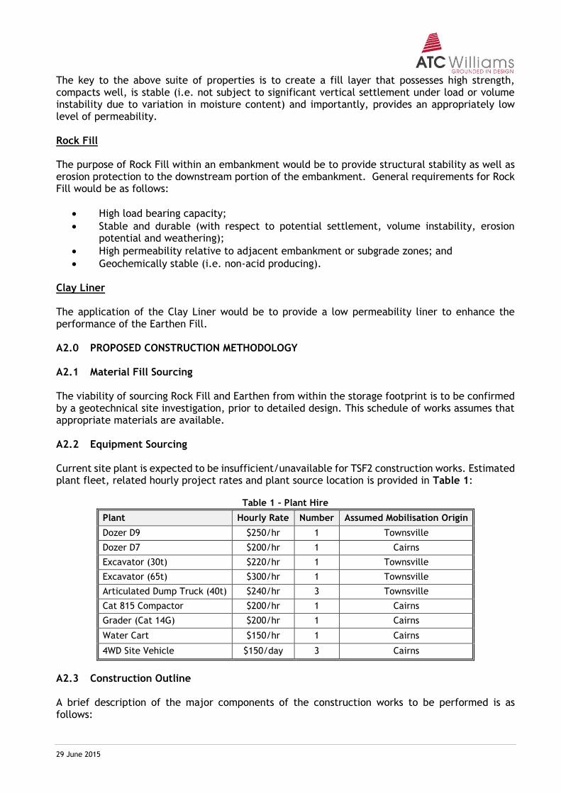
29 June 2015 Schedule of Works
The key to the above suite of properties is to create a fill layer that possesses high strength, compacts well, is stable (i.e. not subject to significant vertical settlement under load or volume instability due to variation in moisture content) and importantly, provides an appropriately low level of permeability. Rock Fill The purpose of Rock Fill within an embankment would be to provide structural stability as well as erosion protection to the downstream portion of the embankment. General requirements for Rock Fill would be as follows:
High load bearing capacity;
Stable and durable (with respect to potential settlement, volume instability, erosion potential and weathering);
High permeability relative to adjacent embankment or subgrade zones; and
Geochemically stable (i.e. non-acid producing). Clay Liner The application of the Clay Liner would be to provide a low permeability liner to enhance the performance of the Earthen Fill. A2.0 PROPOSED CONSTRUCTION METHODOLOGY A2.1 Material Fill Sourcing The viability of sourcing Rock Fill and Earthen from within the storage footprint is to be confirmed by a geotechnical site investigation, prior to detailed design. This schedule of works assumes that appropriate materials are available. A2.2 Equipment Sourcing Current site plant is expected to be insufficient/unavailable for TSF2 construction works. Estimated plant fleet, related hourly project rates and plant source location is provided in Table 1:
Table 1 – Plant Hire
Plant Hourly Rate Number Assumed Mobilisation Origin
Dozer D9 $250/hr 1 Townsville
Dozer D7 $200/hr 1 Cairns
Excavator (30t) $220/hr 1 Townsville
Excavator (65t) $300/hr 1 Townsville
Articulated Dump Truck (40t) $240/hr 3 Townsville
Cat 815 Compactor $200/hr 1 Cairns
Grader (Cat 14G) $200/hr 1 Cairns
Water Cart $150/hr 1 Cairns
4WD Site Vehicle $150/day 3 Cairns
A2.3 Construction Outline A brief description of the major components of the construction works to be performed is as follows:
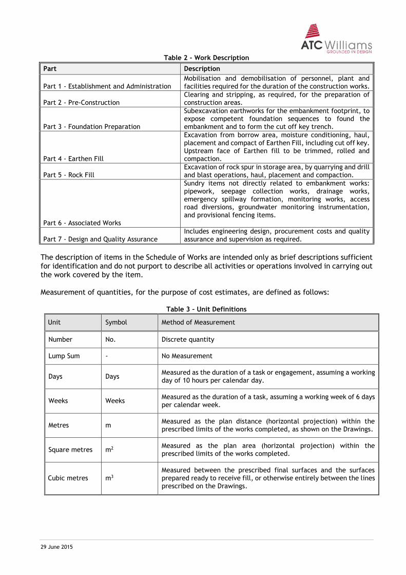
29 June 2015 Schedule of Works
Table 2 – Work Description
Part Description
Part 1 - Establishment and Administration Mobilisation and demobilisation of personnel, plant and facilities required for the duration of the construction works.
Part 2 - Pre-Construction Clearing and stripping, as required, for the preparation of construction areas.
Part 3 - Foundation Preparation
Subexcavation earthworks for the embankment footprint, to expose competent foundation sequences to found the embankment and to form the cut off key trench.
Part 4 - Earthen Fill
Excavation from borrow area, moisture conditioning, haul, placement and compact of Earthen Fill, including cut off key. Upstream face of Earthen fill to be trimmed, rolled and compaction.
Part 5 - Rock Fill Excavation of rock spur in storage area, by quarrying and drill and blast operations, haul, placement and compaction.
Part 6 - Associated Works
Sundry items not directly related to embankment works: pipework, seepage collection works, drainage works, emergency spillway formation, monitoring works, access road diversions, groundwater monitoring instrumentation, and provisional fencing items.
Part 7 - Design and Quality Assurance Includes engineering design, procurement costs and quality assurance and supervision as required.
The description of items in the Schedule of Works are intended only as brief descriptions sufficient for identification and do not purport to describe all activities or operations involved in carrying out the work covered by the item. Measurement of quantities, for the purpose of cost estimates, are defined as follows:
Table 3 – Unit Definitions
Unit Symbol Method of Measurement
Number No. Discrete quantity
Lump Sum - No Measurement
Days Days Measured as the duration of a task or engagement, assuming a working day of 10 hours per calendar day.
Weeks Weeks Measured as the duration of a task, assuming a working week of 6 days per calendar week.
Metres m Measured as the plan distance (horizontal projection) within the prescribed limits of the works completed, as shown on the Drawings.
Square metres m2 Measured as the plan area (horizontal projection) within the prescribed limits of the works completed.
Cubic metres m3 Measured between the prescribed final surfaces and the surfaces prepared ready to receive fill, or otherwise entirely between the lines prescribed on the Drawings.
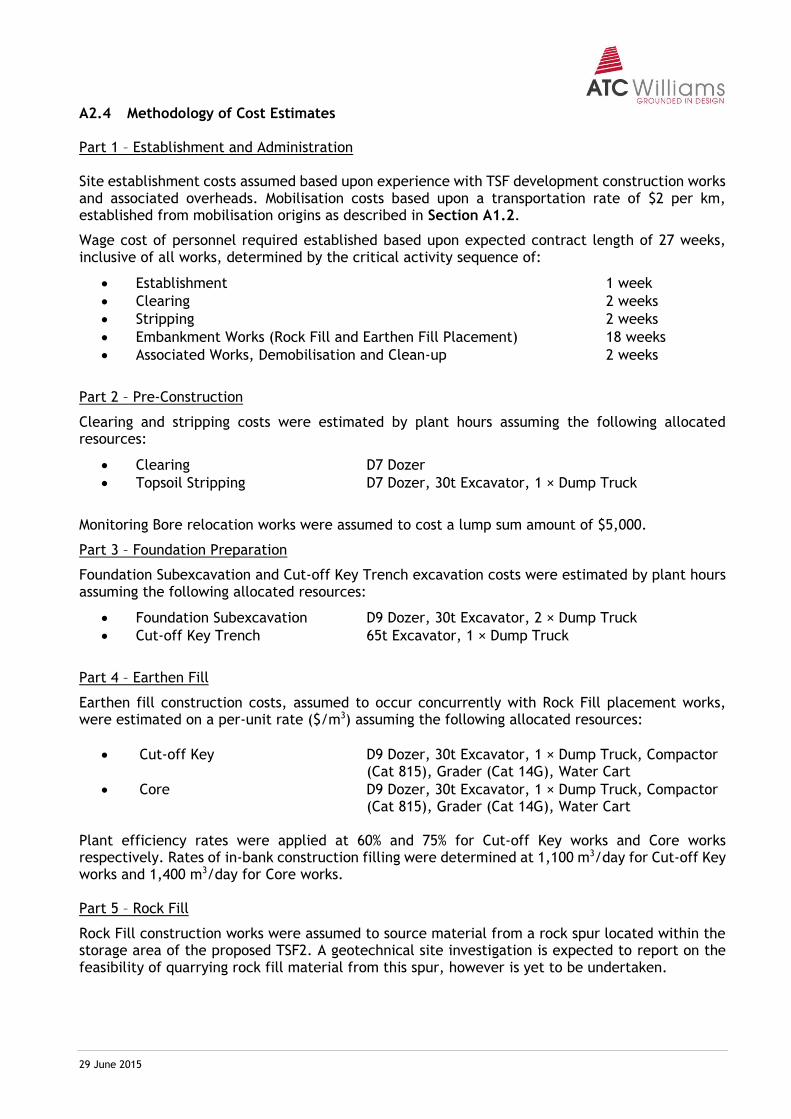
29 June 2015 Schedule of Works
A2.4 Methodology of Cost Estimates Part 1 – Establishment and Administration Site establishment costs assumed based upon experience with TSF development construction works and associated overheads. Mobilisation costs based upon a transportation rate of $2 per km, established from mobilisation origins as described in Section A1.2.
Wage cost of personnel required established based upon expected contract length of 27 weeks, inclusive of all works, determined by the critical activity sequence of:
Establishment 1 week
Clearing 2 weeks
Stripping 2 weeks
Embankment Works (Rock Fill and Earthen Fill Placement) 18 weeks
Associated Works, Demobilisation and Clean-up 2 weeks
Part 2 – Pre-Construction
Clearing and stripping costs were estimated by plant hours assuming the following allocated resources:
Clearing D7 Dozer
Topsoil Stripping D7 Dozer, 30t Excavator, 1 × Dump Truck
Monitoring Bore relocation works were assumed to cost a lump sum amount of $5,000.
Part 3 – Foundation Preparation
Foundation Subexcavation and Cut-off Key Trench excavation costs were estimated by plant hours assuming the following allocated resources:
Foundation Subexcavation D9 Dozer, 30t Excavator, 2 × Dump Truck
Cut-off Key Trench 65t Excavator, 1 × Dump Truck
Part 4 – Earthen Fill
Earthen fill construction costs, assumed to occur concurrently with Rock Fill placement works, were estimated on a per-unit rate ($/m3) assuming the following allocated resources:
Cut-off Key D9 Dozer, 30t Excavator, 1 × Dump Truck, Compactor (Cat 815), Grader (Cat 14G), Water Cart
Core D9 Dozer, 30t Excavator, 1 × Dump Truck, Compactor (Cat 815), Grader (Cat 14G), Water Cart
Plant efficiency rates were applied at 60% and 75% for Cut-off Key works and Core works respectively. Rates of in-bank construction filling were determined at 1,100 m3/day for Cut-off Key works and 1,400 m3/day for Core works. Part 5 – Rock Fill
Rock Fill construction works were assumed to source material from a rock spur located within the storage area of the proposed TSF2. A geotechnical site investigation is expected to report on the feasibility of quarrying rock fill material from this spur, however is yet to be undertaken.
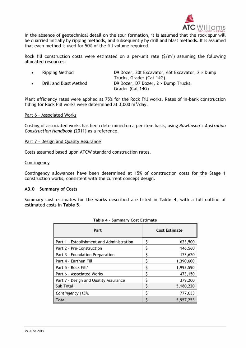
29 June 2015 Schedule of Works
In the absence of geotechnical detail on the spur formation, it is assumed that the rock spur will be quarried initially by ripping methods, and subsequently by drill and blast methods. It is assumed that each method is used for 50% of the fill volume required. Rock fill construction costs were estimated on a per-unit rate ($/m3) assuming the following allocated resources:
Ripping Method D9 Dozer, 30t Excavator, 65t Excavator, 2 × Dump Trucks, Grader (Cat 14G)
Drill and Blast Method D9 Dozer, D7 Dozer, 2 × Dump Trucks, Grader (Cat 14G)
Plant efficiency rates were applied at 75% for the Rock Fill works. Rates of in-bank construction filling for Rock Fill works were determined at 3,000 m3/day. Part 6 – Associated Works Costing of associated works has been determined on a per item basis, using Rawlinson’s Australian Construction Handbook (2011) as a reference. Part 7 – Design and Quality Assurance Costs assumed based upon ATCW standard construction rates. Contingency Contingency allowances have been determined at 15% of construction costs for the Stage 1 construction works, consistent with the current concept design. A3.0 Summary of Costs Summary cost estimates for the works described are listed in Table 4, with a full outline of estimated costs in Table 5.
Table 4 – Summary Cost Estimate
Part Cost Estimate
Part 1 - Establishment and Administration $ 623,500
Part 2 - Pre-Construction $ 146,560
Part 3 - Foundation Preparation $ 173,620
Part 4 - Earthen Fill $ 1,390,600
Part 5 - Rock Fill* $ 1,993,590
Part 6 - Associated Works $ 473,150
Part 7 - Design and Quality Assurance $ 379,200
Sub Total $ 5,180,220
Contingency (15%) $ 777,033
Total $ 5,957,253
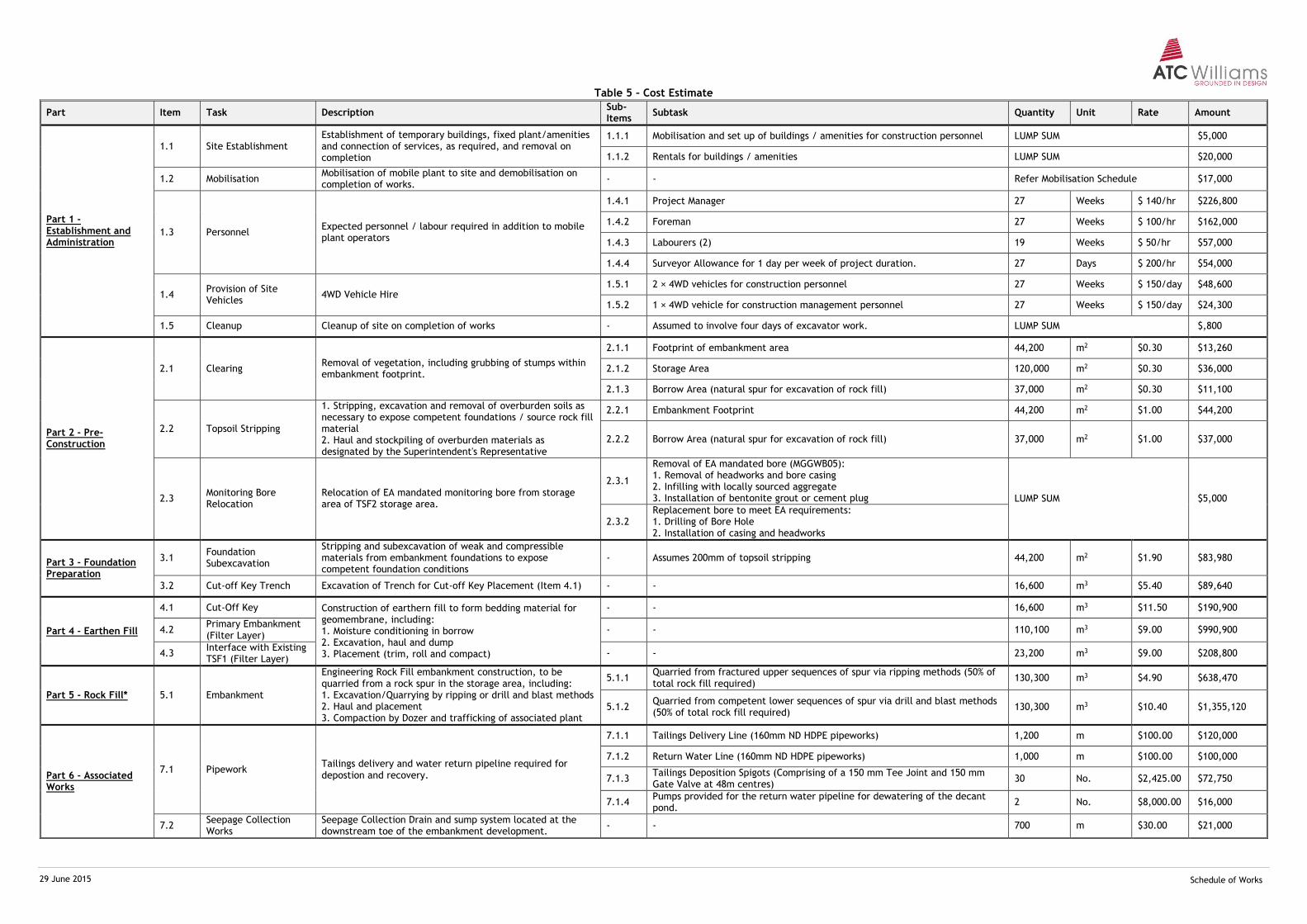
29 June 2015 Schedule of Works
Table 5 – Cost Estimate
Part Item Task Description Sub-Items
Subtask Quantity Unit Rate Amount
Part 1 - Establishment and Administration
1.1 Site Establishment Establishment of temporary buildings, fixed plant/amenities and connection of services, as required, and removal on completion
1.1.1 Mobilisation and set up of buildings / amenities for construction personnel LUMP SUM $5,000
1.1.2 Rentals for buildings / amenities LUMP SUM $20,000
1.2 Mobilisation Mobilisation of mobile plant to site and demobilisation on completion of works.
- - Refer Mobilisation Schedule $17,000
1.3 Personnel Expected personnel / labour required in addition to mobile plant operators
1.4.1 Project Manager 27 Weeks $ 140/hr $226,800
1.4.2 Foreman 27 Weeks $ 100/hr $162,000
1.4.3 Labourers (2) 19 Weeks $ 50/hr $57,000
1.4.4 Surveyor Allowance for 1 day per week of project duration. 27 Days $ 200/hr $54,000
1.4 Provision of Site Vehicles
4WD Vehicle Hire 1.5.1 2 × 4WD vehicles for construction personnel 27 Weeks $ 150/day $48,600
1.5.2 1 × 4WD vehicle for construction management personnel 27 Weeks $ 150/day $24,300
1.5 Cleanup Cleanup of site on completion of works - Assumed to involve four days of excavator work. LUMP SUM $,800
Part 2 - Pre-Construction
2.1 Clearing Removal of vegetation, including grubbing of stumps within embankment footprint.
2.1.1 Footprint of embankment area 44,200 m2 $0.30 $13,260
2.1.2 Storage Area 120,000 m2 $0.30 $36,000
2.1.3 Borrow Area (natural spur for excavation of rock fill) 37,000 m2 $0.30 $11,100
2.2 Topsoil Stripping
1. Stripping, excavation and removal of overburden soils as necessary to expose competent foundations / source rock fill material 2. Haul and stockpiling of overburden materials as designated by the Superintendent's Representative
2.2.1 Embankment Footprint 44,200 m2 $1.00 $44,200
2.2.2 Borrow Area (natural spur for excavation of rock fill) 37,000 m2 $1.00 $37,000
2.3 Monitoring Bore Relocation
Relocation of EA mandated monitoring bore from storage area of TSF2 storage area.
2.3.1
Removal of EA mandated bore (MGGWB05): 1. Removal of headworks and bore casing 2. Infilling with locally sourced aggregate 3. Installation of bentonite grout or cement plug LUMP SUM $5,000
2.3.2 Replacement bore to meet EA requirements: 1. Drilling of Bore Hole 2. Installation of casing and headworks
Part 3 - Foundation Preparation
3.1 Foundation Subexcavation
Stripping and subexcavation of weak and compressible materials from embankment foundations to expose competent foundation conditions
- Assumes 200mm of topsoil stripping 44,200 m2 $1.90 $83,980
3.2 Cut-off Key Trench Excavation of Trench for Cut-off Key Placement (Item 4.1) - - 16,600 m3 $5.40 $89,640
Part 4 - Earthen Fill
4.1 Cut-Off Key Construction of earthern fill to form bedding material for geomembrane, including: 1. Moisture conditioning in borrow 2. Excavation, haul and dump 3. Placement (trim, roll and compact)
- - 16,600 m3 $11.50 $190,900
4.2 Primary Embankment (Filter Layer)
- - 110,100 m3 $9.00 $990,900
4.3 Interface with Existing TSF1 (Filter Layer)
- - 23,200 m3 $9.00 $208,800
Part 5 - Rock Fill* 5.1 Embankment
Engineering Rock Fill embankment construction, to be quarried from a rock spur in the storage area, including: 1. Excavation/Quarrying by ripping or drill and blast methods 2. Haul and placement 3. Compaction by Dozer and trafficking of associated plant
5.1.1 Quarried from fractured upper sequences of spur via ripping methods (50% of total rock fill required)
130,300 m3 $4.90 $638,470
5.1.2 Quarried from competent lower sequences of spur via drill and blast methods (50% of total rock fill required)
130,300 m3 $10.40 $1,355,120
Part 6 - Associated Works
7.1 Pipework Tailings delivery and water return pipeline required for depostion and recovery.
7.1.1 Tailings Delivery Line (160mm ND HDPE pipeworks) 1,200 m $100.00 $120,000
7.1.2 Return Water Line (160mm ND HDPE pipeworks) 1,000 m $100.00 $100,000
7.1.3 Tailings Deposition Spigots (Comprising of a 150 mm Tee Joint and 150 mm Gate Valve at 48m centres)
30 No. $2,425.00 $72,750
7.1.4 Pumps provided for the return water pipeline for dewatering of the decant pond.
2 No. $8,000.00 $16,000
7.2 Seepage Collection Works
Seepage Collection Drain and sump system located at the downstream toe of the embankment development.
- - 700 m $30.00 $21,000
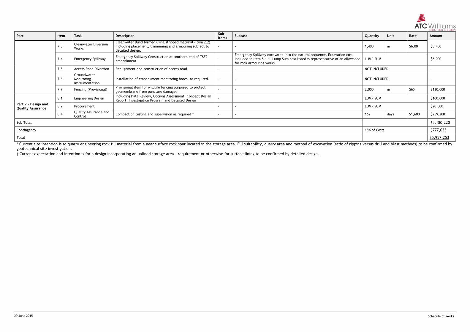
29 June 2015 Schedule of Works
Part Item Task Description Sub-Items
Subtask Quantity Unit Rate Amount
7.3 Cleanwater Diversion Works
Cleanwater Bund formed using stripped material (Item 2.2), including placement, trimmming and armouring subject to detailed design.
- - 1,400 m $6.00 $8,400
7.4 Emergency Spillway Emergency Spillway Construction at southern end of TSF2 embankment
- Emergency Spillway excavated into the natural sequence. Excavation cost included in Item 5.1.1. Lump Sum cost listed is representative of an allowance for rock armouring works.
LUMP SUM $5,000
7.5 Access Road Diversion Realignment and construction of access road - - NOT INCLUDED -
7.6 Groundwater Monitoring Instrumentation
Installation of embankment monitoring bores, as required. - - NOT INCLUDED -
7.7 Fencing (Provisional) Provisional item for wildlife fencing purposed to protect geomembrane from puncture damage.
- - 2,000 m $65 $130,000
Part 7 - Design and Quality Assurance
8.1 Engineering Design Including Data Review, Options Assessment, Concept Design Report, Investigation Program and Detailed Design
- LUMP SUM $100,000
8.2 Procurement - - LUMP SUM $20,000
8.4 Quality Assurance and Control
Compaction testing and supervision as required † - - 162 days $1,600 $259,200
Sub Total $5,180,220
Contingency 15% of Costs $777,033
Total $5,957,253
* Current site intention is to quarry engineering rock fill material from a near surface rock spur located in the storage area. Fill suitability, quarry area and method of excavation (ratio of ripping versus drill and blast methods) to be confirmed by geotechnical site investigation.
† Current expectation and intention is for a design incorporating an unlined storage area - requirement or otherwise for surface lining to be confirmed by detailed design.

P R O P O S A L
A P P E N D I X B

Methodology Statement – Design Storage Allowance (DSA)
Page No. 1 of 3
M:\Synergy\Projects\111\111282 Kagara Zinc Ltd - Mt Garnet\09 Tailings Dam Options\Reports\R02 (Concept Design Report)\Appendix B.doc
Appendix B The following table lists the assumptions and methodology adopted for the calculation of DSA for the project site. The DSA calculation results are detailed in the report (Refer Section 6.1). The methodology is compared to the process described in the Manual for Assessing Consequence Categories and Hydraulic Performance of Structures: Appendix A - Example methods for estimating the design storage allowance (DEHP, 2013). The rainfall station considered was:
Mt Garnet Post Office Station BOM ID: 31046
Method of Deciles – Methodology Details
Method of Deciles as per DEHP (2013) Details
To be suitable for this analysis, the nearby rainfall station must:
1. have at least 50 years of usable record 75 years of useable data
2. for any particular year, the record in that year must include the wet
season for that year; and
Only years with a complete
record over the wet season
were used for the analysis
3. be located within the same basin as the site where the dam is/is
proposed to be constructed or operated. In large river basins the
rainfall station should, as a minimum, be located in the catchment of
tributary rivers.
Located within the (lower) Herbert basin, approximately 1 km from the site location
4. If no suitable daily rainfall station records exist, then Silo Data Drill
for a point within the site of the proposed dam may be used.
Rainfall Station Data utilised
5. The duration of a critical wet period should be determined from
Figure 1, based on the physical location of the site relative to river
basins in Queensland.
Figure 1. Critical wet periods for methods of deciles analysis
As per Figure 1: the critical
duration for the site location
is a 3 month wet season
SITE LOCATION
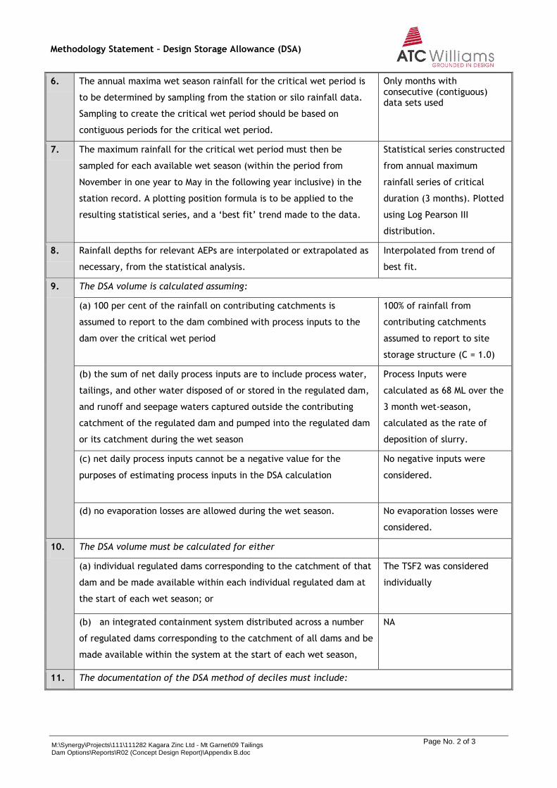
Methodology Statement – Design Storage Allowance (DSA)
Page No. 2 of 3
M:\Synergy\Projects\111\111282 Kagara Zinc Ltd - Mt Garnet\09 Tailings Dam Options\Reports\R02 (Concept Design Report)\Appendix B.doc
6. The annual maxima wet season rainfall for the critical wet period is
to be determined by sampling from the station or silo rainfall data.
Sampling to create the critical wet period should be based on
contiguous periods for the critical wet period.
Only months with consecutive (contiguous) data sets used
7. The maximum rainfall for the critical wet period must then be
sampled for each available wet season (within the period from
November in one year to May in the following year inclusive) in the
station record. A plotting position formula is to be applied to the
resulting statistical series, and a ‘best fit’ trend made to the data.
Statistical series constructed
from annual maximum
rainfall series of critical
duration (3 months). Plotted
using Log Pearson III
distribution.
8. Rainfall depths for relevant AEPs are interpolated or extrapolated as
necessary, from the statistical analysis.
Interpolated from trend of
best fit.
9. The DSA volume is calculated assuming:
(a) 100 per cent of the rainfall on contributing catchments is
assumed to report to the dam combined with process inputs to the
dam over the critical wet period
100% of rainfall from
contributing catchments
assumed to report to site
storage structure (C = 1.0)
(b) the sum of net daily process inputs are to include process water,
tailings, and other water disposed of or stored in the regulated dam,
and runoff and seepage waters captured outside the contributing
catchment of the regulated dam and pumped into the regulated dam
or its catchment during the wet season
Process Inputs were
calculated as 68 ML over the
3 month wet-season,
calculated as the rate of
deposition of slurry.
(c) net daily process inputs cannot be a negative value for the
purposes of estimating process inputs in the DSA calculation
No negative inputs were
considered.
(d) no evaporation losses are allowed during the wet season. No evaporation losses were
considered.
10. The DSA volume must be calculated for either
(a) individual regulated dams corresponding to the catchment of that
dam and be made available within each individual regulated dam at
the start of each wet season; or
The TSF2 was considered
individually
(b) an integrated containment system distributed across a number
of regulated dams corresponding to the catchment of all dams and be
made available within the system at the start of each wet season,
NA
11. The documentation of the DSA method of deciles must include:

Methodology Statement – Design Storage Allowance (DSA)
Page No. 3 of 3
M:\Synergy\Projects\111\111282 Kagara Zinc Ltd - Mt Garnet\09 Tailings Dam Options\Reports\R02 (Concept Design Report)\Appendix B.doc
(a) rainfall data sources; statistical analyses; and determined AEP
wet season rainfall depths
Refer to Section 3.1
(b) catchments including maps, quantified areas, and assumptions
of catchment diversion works
Catchments consist of area
of raised TSF only.
(c) basis of process inputs into the DSA calculation including
necessary procedures or operations to ensure that process inputs do
not exceed the allowance in the DSA volume estimate
Refer to Section 6.2
(d) where relevant, assumptions, constraints, operations, and
procedures relied upon to distribute DSA allowance for an integrated
containment system across a number of regulated dams.
NA - Integrated Containment
System not assumed

P R O P O S A L
A P P E N D I X C
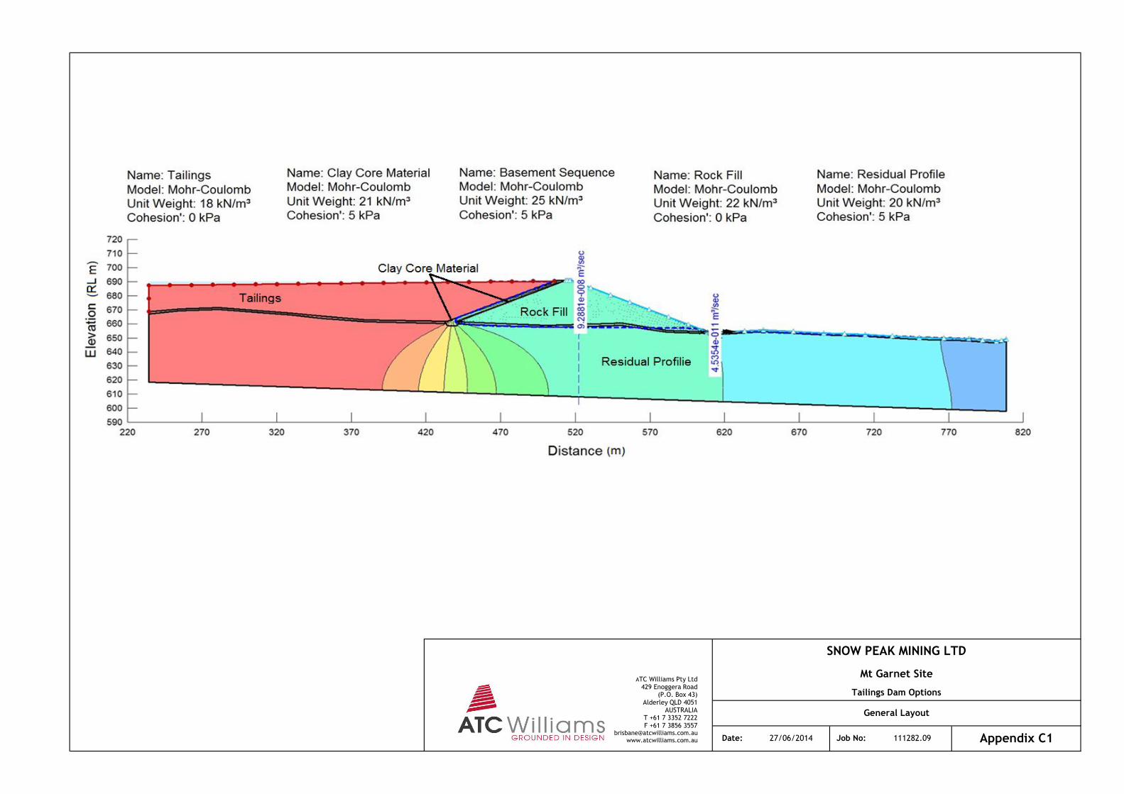
SNOW PEAK MINING LTD
Mt Garnet Site
Tailings Dam Options
General Layout
Appendix C1Date: 27/06/2014 Job No: 111282.09
ATC Williams Pty Ltd 429 Enoggera Road
(P.O. Box 43) Alderley QLD 4051
AUSTRALIA T +61 7 3352 7222 F +61 7 3856 3557
[email protected] www.atcwilliams.com.au
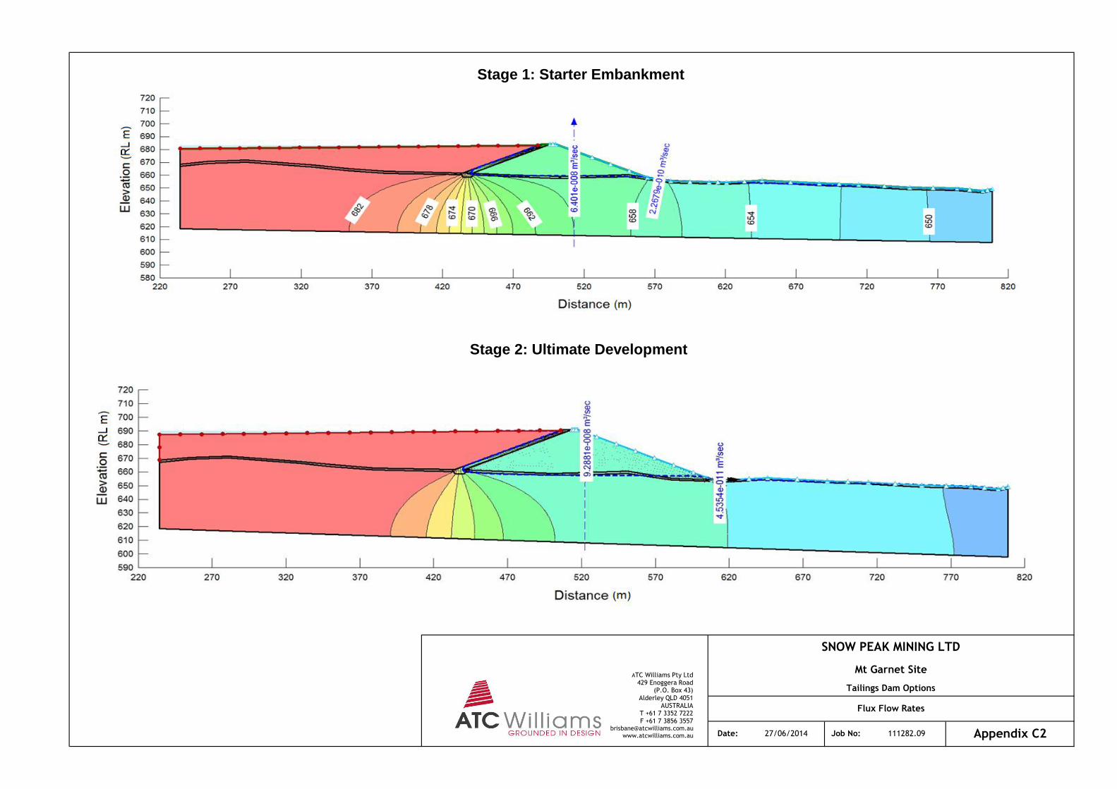
Stage 1: Starter Embankment
Stage 2: Ultimate Development
SNOW PEAK MINING LTD
Mt Garnet Site
Tailings Dam Options
Flux Flow Rates
Date: 27/06/2014 Job No: 111282.09 Appendix C2
ATC Williams Pty Ltd 429 Enoggera Road
(P.O. Box 43) Alderley QLD 4051
AUSTRALIA T +61 7 3352 7222 F +61 7 3856 3557
[email protected] www.atcwilliams.com.au
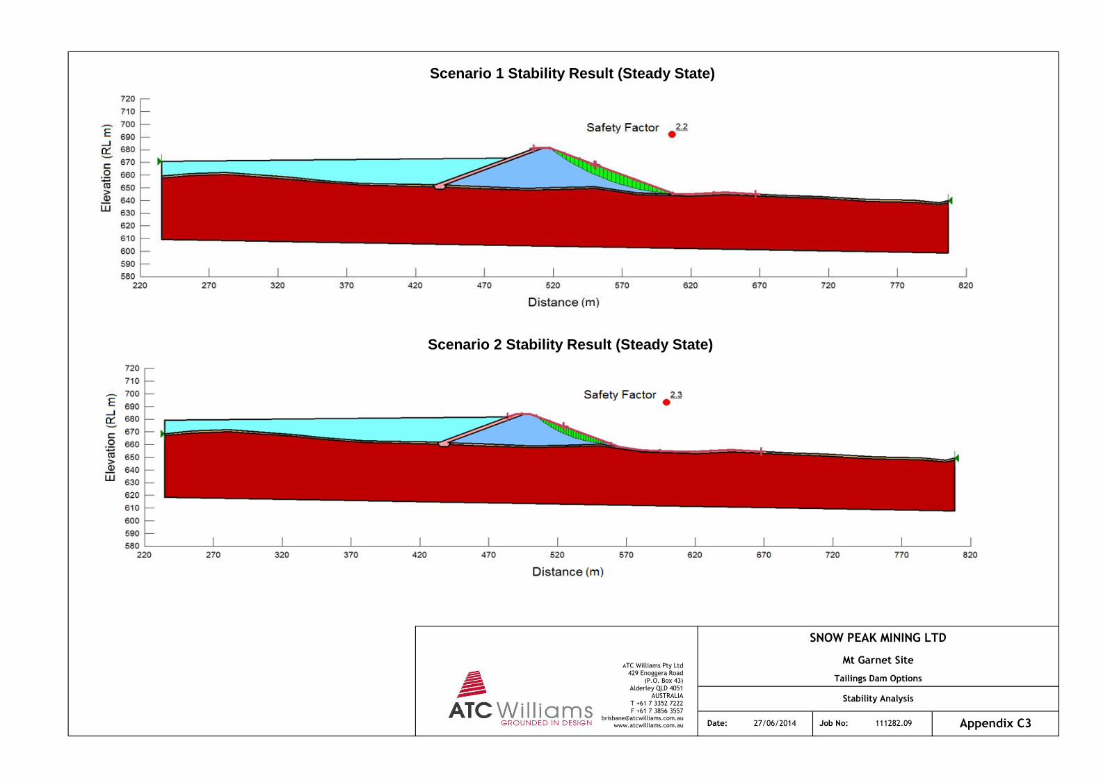
Date: 27/06/2014 Job No: 111282.09 Appendix C3
Scenario 1 Stability Result (Steady State)
Scenario 2 Stability Result (Steady State)
SNOW PEAK MINING LTD
Mt Garnet Site
Tailings Dam Options
Stability Analysis
ATC Williams Pty Ltd 429 Enoggera Road
(P.O. Box 43) Alderley QLD 4051
AUSTRALIA T +61 7 3352 7222 F +61 7 3856 3557
[email protected] www.atcwilliams.com.au