Embed Size (px)
Citation preview

Owner’s Manual
Multi-Cutter Precision Saw 54-8333-2
CAUTION: Before using this multi-cutter precision saw or any of its accessories, carefully read this manual and follow all Safety Rules and Operating Instructions.
General Safety Rules Specific Safety Rules
and Symbols Functional Description Assembly Operation Maintenance Accessories
Imported by Mastercraft Canada Toronto, Canada M4S 2B8 Rev 1.2 13/01/2009

2
SECTION PAGE SECTION PAGE Warranty ….………………………. 2 Know your multi-cutter …...….. 8 Product specifications …………... 3 Tote contents ………..………... 9–10 Power tool safety ………………… 3–5 Assembly & operation ..……… 11–18 Specific safety rules …………….. 6 Maintenance …….…………….. 19 Extension cords …………………. 6–7 Parts & service ..……..……….. 20–22 Symbols ………………………….. 7
WARRANTY
TABLE OF CONTENTS TABLE OF CONTENTS
Limited 3-year Replacement Warranty This Mastercraft product carries a three (3) year replacement warranty against
defects in workmanship and materials. Mastercraft Canada agrees to replace the defective product free of charge with the same model or one of equal value or specification, within the stated warranty period, when returned by the original purchaser with proof of purchase. This product is not guaranteed against wear or
breakage due to misuse and/or abuse. This product is not guaranteed if used for industrial or commercial purposes. Mastercraft is a superior line of products selected for their workmanship and materials. These products are designed to meet rigorous quality and performance standards, and are approved by our Quality Assurance laboratory.
TOLL FREE HELPLINE: 1-800-689-9928

3
WARNING: To avoid electrical hazards, fire hazards, or damage to the multi-
cutter precision saw, use proper circuit protection. This multi-cutter precision saw is wired at the factory for 110–120 V operation. It must be connected to a 110–120 V 15 A time delayed fuse or circuit breaker. To avoid shock or fire, replace the power cord immediately if it is worn, cut or damaged in any way.
!
PRODUCT SPECIFICATIONS
Rating ……………………………….. 120 V, 60 Hz, AC Amperes ……………………………. 4.0 Amperes Speed ………………………………. 4000 RPM (no load) Blade diameter …………………….. 85 mm (3
5/16”)
Arbor ………………………………… 10 mm Depth of cut ………………………… 0–26.9 mm (0–1
1/16”)
Edge guide …………………………. 170 mm (6 ¾”)
WARNING: Dust created by power sanding, sawing, grinding, drilling and
other construction activities may contain chemicals that are known to cause cancer, birth defects or other genetic abnormalities. These chemicals include:
Lead from lead-based paints
Crystalline silica from bricks, cement and other masonry products
Arsenic and chromium from chemically-treated lumber Your level of risk from exposure to these chemicals will vary, according to how often you do this type of work. To reduce your exposure to these chemicals, work in a well-ventilated area and use approved safety equipment such as dust masks
that are specially designed to filter out microscopic particles.
!
POWER TOOL SAFETY
!
Always wear eye protection.
Any power tool can throw foreign objects into your eyes, which could cause permanent eye damage. ALWAYS wear safety goggles (not glasses) that comply with ANSI safety standard Z87.1. Everyday glasses only have impact resistant lenses. They ARE NOT safety glasses.
WARNING: Glasses or goggles that do not comply with ANSI Z87.1 could
cause serious injury if they break.
SAVE THESE INSTRUCTIONS FOR REFERENCE
DANGER: The laser light beam that is projected from the front of the laser
level can be dangerous to eyesight. Never allow anyone to stare directly into the
light. Staring directly into the light beam may result in serious eye damage.
!

4
GENERAL SAFETY RULES
WARNING: Read and understand
all instructions. Failure to follow all of the
instructions listed below may result in electric shock, fire and/or serious personal injury. WORK AREA Keep your work area clean and well-lit.
Cluttered benches and dark areas invite accidents. Do not operate power tools in a potentially explosive environment, such as in the presence of flammable liquids, gases or dust. Power tools create sparks,
which may ignite the dust or fumes. Keep bystanders, children and visitors away while operating a power tool.
Distractions can cause you to lose control. ELECTRICAL SAFETY Double insulated tools are equipped with a polarized plug (one blade is wider than the other). This plug will fit into a polarized outlet only one way. If the plug does not fit into the outlet, reverse the plug. If it still does not fit, contact a qualified electrician to install a polarized outlet. Do not alter the plug in any way.
Double insulation eliminates the need for the three-prong grounded power cord and grounded power supply system. Avoid contact between your body and grounded surfaces such as pipes, radiators, ranges and refrigerators. There is an increased risk of electric shock if your body is grounded.
Do not expose power tools to rain or wet conditions. Water entering the power
tool will increase the risk of electric shock. Do not abuse the cord. Never use the
cord to carry the tool or to pull the plug out of an outlet. Keep the cord away from heat, oil, sharp edges, and moving parts. Replace damaged cords immediately. Damaged cords increase the risk of electric shock.
When operating a power tool outdoors, use an outdoor extension cord marked “W-A” or “W”. These cords are rated for
outdoor use and reduce the risk of electric shock.
PERSONAL SAFETY
Stay alert, watch what you are doing and use common sense when operating a power tool. Do not use the tool when tired or under the influence of drugs, alcohol, or medication. A moment of
inattention while operating a power tool could result in serious personal injury.
Dress properly. Do not wear loose clothing or jewellery.
Contain long hair. Keep your hair, clothing and gloves away from moving parts. Loose clothing, jewellery or long hair
can be caught in moving parts.
Avoid accidental starting. Verify that the switch is in the OFF position before plugging the tool in. Carrying tools with
your finger on the switch or plugging in tools that have the switch in the ON position invites accidents.
SAVE THESE INSTRUCTIONS FOR REFERENCE
!
POWER TOOL SAFETY

5
POWER TOOL SAFETY PERSONAL SAFETY – cont’d Remove adjusting keys or wrenches before turning the tool ON. A wrench or
key that is left attached to a rotating part of the tool could result in personal injury.
Do not overreach. Keep proper footing and balance at all times. Proper footing
and balance allows for better control of the tool in unexpected situations. Use safety equipment. Always wear eye protection. A dust mask, non-skid safety
shoes, a hardhat or hearing protection must be used for appropriate conditions. TOOL USE AND CARE
Use clamps or another practical means to secure and support the workpiece to a stable platform. Holding the work in your
hand or against your body is not stable and may lead to loss of control. Do not force the tool. Use the correct tool for your application. The correct tool
will do the job better and safer at the speed that it was designed to work at. Do not use the tool if it cannot be turned ON or OFF by the power switch. Any tool
that cannot be controlled using the switch is dangerous and must be repaired. Disconnect the plug from the power source before making any adjustments, changing accessories or storing the tool. Such preventive safety measures
reduce the risk of starting the tool accidentally.
When not in use, store tools out of reach of children and other untrained persons. Tools are dangerous in the
hands of untrained users. Maintain tools with care. Keep cutting tools sharp and clean. Properly
maintained cutting tools with sharp cutting edges are less likely to bind and are easier to control. Check for misalignment or binding of moving parts, broken parts and any other condition that may affect the operation of the tool. If it is damaged, have the tool serviced before using.
Many accidents are caused by poorly maintained tools. Use only accessories that are recommended for your model by the manufacturer. Accessories that may be
suitable for one tool may become hazardous when used on another tool. SERVICE
Tools must be serviced by qualified personnel only. Service or maintenance
performed by unqualified personnel could result in a risk of injury. When servicing a tool, use only identical replacement parts. Follow instructions in the Maintenance section of this manual. Use of unauthorized parts or
failure to follow Maintenance instructions may result in a risk of electric shock or injury.
SAVE THESE INSTRUCTIONS FOR REFERENCE

6
EXTENSION CORDS
WARNING: Know your multi-cutter
precision saw. Read the Owner’s Manual carefully. Learn the tool’s applications and limitations, as well as the specific potential hazards related to this tool. Following this rule will reduce the
risk of electric shock, fire and serious injury. Always wear eye protection. Any power
tool can throw foreign objects into your eyes, which could cause permanent eye damage. ALWAYS wear safety
goggles (not glasses) that comply with ANSI safety standard Z87.1. Everyday glasses only have impact resistant lenses. They ARE NOT safety glasses.
WARNING: Glasses or goggles
that do not comply with ANSI Z87.1 could cause serious injury if they break. Always wear hearing protection and a dust mask. Dust and high-pitched noise
created when using this high-speed saw can damage your hearing and lungs. Do not wear gloves, neckties or loose
clothing. Always keep hands out of the path of the
saw blade. Avoid awkward hand positions where a sudden slip could cause your hand to move into the path of the saw blade. Do not cut material too small to be
securely held. Secure workpiece. Use clamps or a vice
to hold the work when practical. Both hands are required to operate the tool. Make sure there are no nails or foreign
objects in the area of the workpiece to be cut.
To avoid injury from accidental starting,
always remove the plug from the power source before making any adjustments or installing / removing a saw blade, accessory or attachment.
DANGER: The laser light beam
that is projected from the front of the laser level can be dangerous to eyesight. Never allow anyone to stare directly into the light. Staring directly into the light beam may result in serious eye damage.
DANGER: Never use the laser
level in the presence of small children.
Small children may stare directly into the laser light beam causing serious eye injury.
WARNING: Keep the extension
cord clear of the working area. Position the cord so that it will not get caught on the workpiece, tools or any other obstructions while you are working with the power tool. Make sure any extension cord that is used with this tool is in good condition.
When using an extension cord, be sure to use one that is heavy enough to carry the current that the tool will draw. An undersized cord will cause a drop in line voltage which will result in loss of power and overheating. The table on the following page shows the correct size to be used according to cord length and nameplate ampere rating. When in doubt, use the next heavier gauge. The smaller the gauge number the heavier the cord.
SPECIFIC SAFETY RULES
!
!
!
!
SAVE THESE INSTRUCTIONS FOR REFERENCE
!

7
EXTENSION CORD SAFETY
SYMBOLS
Be sure your extension cord is properly wired and in good condition. Always
replace a damaged extension cord or have it repaired by a qualified electrician before using it. Protect your extension cord from sharp objects, excessive heat and damp or wet areas. Use a separate electrical circuit for your power tools. This circuit must consist of
not less than 14 gauge wire and should be protected with either a 15 A time delayed fuse or a circuit breaker. Before connecting the power tool to the power source, make sure the switch is in the OFF position and the power source is the same as indicated on the nameplate. Running at lower voltage will damage the motor.
V Volts
A Amperes
Hz Hertz
W Watts
KW Kilowatts
Microfarads
L Litres
Kg Kilograms
H Hours
N/cm2 Newtons per square centimetre
Pa Pascals
Min Minutes
S Seconds
Alternating current
Three-phase alternating current
Three-phase alternating current with neutral
Direct current
No load speed
Alternating or direct current
Class II construction
Splash proof construction
Watertight construction
Protective grounding at grounding terminal, Class I tools
Revolutions or reciprocations per minute
Diameter
Off position
Arrow
Warning symbol
MINIMUM GAUGE (AWG) EXTENSION CORDS
(120 V use only)
Ampere Rating Total length in feet
More Than
Not More Than
25’
50’
100’
150’
0 6 18 16 16 14
6 10 18 16 14 12
10 12 16 16 14 12
12 16 14 12 Not Applicable
WARNING: Some of the following
symbols may appear on your tool. Please study them and learn their meanings. Proper interpretation of these symbols will allow you to
operate the tool better and safer.
!
This symbol designates that this tool is listed with Canadian requirements by ETL.
8
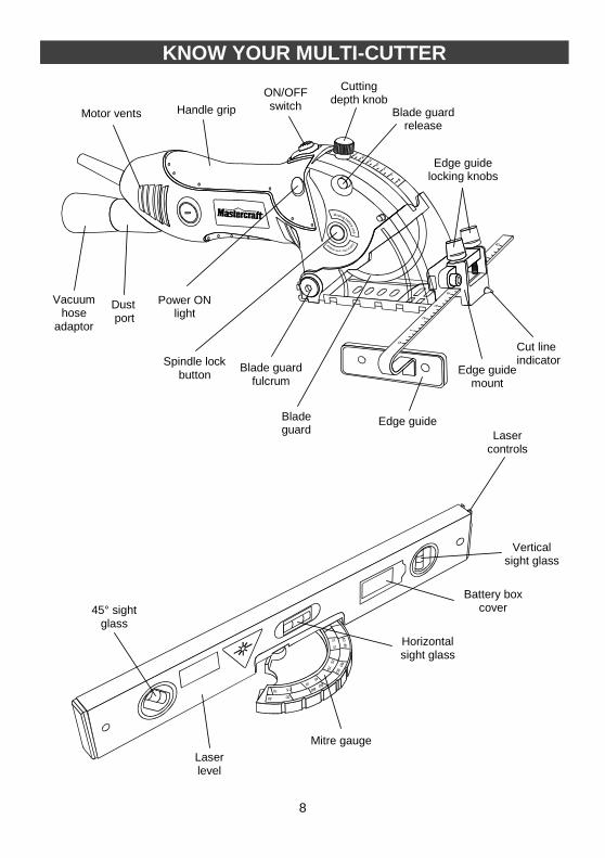
KNOW YOUR MULTI-CUTTER
Laser controls
45° sight glass
Mitre gauge
Laser level
Motor vents
Power ON light
Cutting depth knob
Blade guard
Cut line indicator Spindle lock
button
Handle grip
Blade guard fulcrum
ON/OFF switch
Dust port
Edge guide mount
Blade guard release
Edge guide locking knobs
Edge guide
Battery box cover
Horizontal sight glass
Vertical sight glass
Vacuum hose
adaptor

9
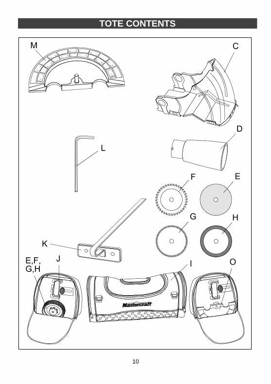
WARNING: If any part is missing
or damaged, do not plug the tool into the power source until the missing or damaged part is replaced.
Carefully unpack the multi-cutter. Compare against the “MULTI-CUTTER COMPONENTS” chart at right. NOTE: See product diagrams on Pages
9 & 10.
WARNING: To avoid fire or toxic
reaction, never use gasoline, naphtha, acetone, lacquer thinner or similar highly volatile solvents to clean the tool.
!
!
TOTE CONTENTS
TOTE CONTENTS
MULTI-CUTTER COMPONENTS KEY DESCRIPTION QTY
A Multi-cutter assembly w/edge guide mount
1
B Spirit/laser level 1
C Pipe cutter attachment 1
D Vacuum hose adaptor 1
E Corundum blade - #54-1077-4
5
F
Carbide tipped blades ● 24 teeth - #54-1072-4 ● 36 teeth - #54-1074-0
1
1
G Super cut blade – #54-1071-6
1
H Diamond wheel – #54-1075-8
1
I Tote 1
J Blade holder 1
K Edge guide 1
L 5 MM Hex key 1
M Mitre gauge 1
Owner’s manual 1
10
TOTE CONTENTS

11
This multi-cutter precision saw is a versatile tool that is designed for use in confined work spaces. By selecting the appropriate cutting blades, it will cut copper and aluminum tubing, ceramic and marble tile, and assorted wood products. The accessory spirit/laser level will also function as a handy mitre guide for scribing cutting marks for most common angles on the workpiece. The following assembly and operating instructions will explain the tool and spirit level in detail. INSTALL VACUUM ADAPTOR
The vacuum adaptor can be used to attach a workshop vacuum hose to the tool. This will prevent most cutting dust from escaping into the work area. 1. Line up the tabs on the small end of
the vacuum adaptor (1) with the matching slots (2) in the vacuum port (3) in the rear of the tool (see Fig. 1).
2. Push the vacuum adaptor into the vacuum port as far as it will go.
3. Twist the vacuum adaptor clockwise to lock it into position.
SECURE CORD TO VACUUM HOSE
Slide the hook and loop strap (1) down the power cord (2) and wrap it around the vacuum hose (3) (see Fig. 2).
REMOVE BLADE GUARD
1. Insert 5 mm hex key (1) into the blade
guard fulcrum nut (2) (see Fig. 3).
2. Turn hex key counter clockwise to remove the blade guard fulcrum nut.
3. Slide blade guard fulcrum bolt (3) out of the blade guard (4).
4. Carefully slide the blade guard off the tool.
REMOVE BLADE
WARNING: Always unplug the tool
from the power source before making any adjustments or changing the blade.
WARNING: Always be extremely
careful when handling blades. They will be extremely hot immediately after use. They are also very sharp and may cause serious injury.
1. Insert the 5 mm hex key (1) into the
arbor screw (2) on the LEFT side of the tool (see Fig. 4).
ASSEMBLY AND OPERATION – MULTI-CUTTER
Fig. 3
!
!
Fig. 2
Fig. 1

12
REMOVE BLADE – cont’d
2. Press inward on the spindle lock
button (3) which is located on the RIGHT side of the tool.
3. Rotate the hex key CLOCKWISE while pressing on the spindle lock button until the spindle lock button engages the spindle.
4. Continue to rotate the arbor screw in a CLOCKWISE direction until the arbor screw is removed and the thick arbor washer (4) can be pulled off the arbor. NOTE: The arbor screw has a left
hand thread. It must be turned CLOCKWISE to be removed.
5. Remove the blade (5).
SELECT THE CORRECT BLADE
Before installing a blade into the tool, it is important to select the correct blade for the type of material being cut.
WARNING: Using the incorrect
blade type can result in damage to the blade and possible injury to the operator.
Blade Profile
Description
Reinforced cutting disc 85 mm x 1.4 mm corundum compound. Cuts non-ferrous metal, plastic & wood
Carbide tipped blade 85 mm x 1.7 mm x 24 teeth 85 mm x 1.7 mm x 36 teeth Cuts aluminum, hardwood, laminates, plastics
HSS Super cut blade 85 mm x 1.0 mm x 80 teeth Cuts hardwood, soft wood & plastics
Diamond coated 85 mm x 1.8 mm Cuts ceramic and marble tile, circuit boards & fiberglass reinforced plastics
INSTALL BLADE
WARNING: Let hot hex nut cool
before attempting to change the blade.
1. Remove existing blade (if one is
installed), arbor screw and thick arbor washer as noted above.
2. Slide blade (5) into the tool so the hole in the blade (6) slides over the arbor (see Fig. 5). NOTE: Make sure the exposed teeth
of a blade with teeth are pointing forward.
3. Re-install thick arbor washer and arbor screw in the reverse order in which they were removed.
Fig. 4
ASSEMBLY AND OPERATION – MULTI-CUTTER
!
!

13
INSTALL BLADE – cont’d
4. Lock spindle using the spindle lock
button and tighten the arbor screw by turning it COUNTER CLOCKWISE. NOTE: The arbor screw has a left
hand thread. It must be turned COUNTER CLOCKWISE to be tightened.
5. Re-install blade guard in the reverse order in which it were removed. NOTE: At this point you must decide
whether to install the universal blade guard or the pipe cutting blade guard.
ADJUST CUTTING DEPTH
The cutting depth is controlled by limiting the amount of blade exposed below the blade guard. 1. Loosen the depth control knob (1) by
turning it counter clockwise (see Fig 6).
2. Slide it upward toward the handle (2) and tighten the knob to hold the depth stop mechanism in place.
3. Press the blade guard lock button (3) and carefully pivot the blade guard (4) upward to expose the amount of blade (5) to achieve the desired depth of cut.
ADJUST CUTTING DEPTH – cont’d
NOTES:
a) The measurement markings on side of the blade guard (6) can be used as a guide in setting the depth of cut. The measurement mark on the guard that intersects with the edge of the blade indicates roughly the depth of cut. b) Always set the cutting depth 1/8” greater than the thickness of the workpiece. c) Always test the depth setting on a scrap workpiece to verify the setting before cutting into the good workpiece.
INSTALL EDGE GUIDE MOUNT
1. Insert the edge guide dovetail (1) into
the matching slot (2) in the front of the blade guard (see Fig 7a).
2. Slide the edge guide mount toward the right hand side of the blade guard until the mounting screw (3) lines up with the matching threaded hole (4) in the blade guard.
3. Carefully turn the mounting screw clockwise into the threaded hole until it holds the edge guide firmly in place.
Fig. 5
Fig. 6
ASSEMBLY AND OPERATION – MULTI-CUTTER

14
INSTALL EDGE GUIDE MOUNT – cont’d
4. Tighten the mounting screw using a
5 mm hex key. NOTE: Do not over tighten the
mounting screw. You will break the blade guard.
INSTALL EDGE GUIDE
The multi-cutter can be used with an edge guide for ripping materials up to 6” wide. 1. Turn two edge guide locking screws
(1) counter clockwise a few turns until the screws rise about 1/8” (see Fig. 7b).
2. Insert edge guard rod (2) into the edge guide mounting block slot (3).
3. Slide edge guard toward the tool until the desired width of cut is indicated on the scale (4) where it meets the edge of the edge guide mounting block.
4. Tighten both edge guide locking screws. NOTES:
a) Do not over tighten the edge guide locking screws or you will break the edge guide mounting block. b) The edge guide scale is only an approximate measurement. Always check the width of cut on a scrap workpiece.
Fig. 7b
ASSEMBLY AND OPERATION – MULTI-CUTTER
Have you read “POWER TOOL SAFETY”, “SPECIFIC SAFETY RULES”, EXTENSION CORD SAFETY” and “SYMBOLS” on pages 3, 4, 5, 6 & 7 of this Manual? If not, please do it now before you operate this multi-cutter. Your safety depends on it! Every time you use the multi-cutter you should verify the following: 1. Correct blade is installed for the
material being cut. 2. Blade is in good condition and
properly installed. 3. Blade guard is in place and in
good working order. 4. Workpiece is properly secured. 5. Safety glasses are being worn. Failure to adhere to these safety rules can greatly increase the chances of injury.
WARNING !
Fig. 7a

15
ON/OFF SWITCH
This tool has dual purpose ON/OFF switch that is designed to prevent accidental starting of the tool. It also automatically turns the tool OFF then the switch is not held in the ON position. 1. Press the center of the switch (1)
inward (see Fig. 8).
2. While holding the center of the switch inward, slide the switch button (2) forward until the tool starts.
3. To stop the tool, release the switch button. It will automatically turn the tool OFF.
CUTTING (without edge guide)
WARNING: Always use two hands on the tool when cutting. This will make operation of the tool easier and promote maximum safety.
1. Install appropriate cutting blade in the
tool.
2. Adjust cutting depth as outlined on Page 13.
3. Plug the tool cord into the power
source. NOTE: The green “power on” light (1)
on the right hand side of the tool will illuminate when power is “live” (see Fig. 9).
4. Place leading edge of the blade guard
(2) on the workpiece to be cut (see Fig. 10).
5. Grasp the tool with two hands. Place your right hand on the body of the tool (3) being careful not to cover the motor vents (4). Place your left hand on the forward part of the tool (5) so your thumb can operate the blade guard release button (6).
6. Line up front cut line indicator (7) with the cutting line marked on the workpiece (8). NOTE: Do not place the blade guard
too far forward on the workpiece. This is important to avoid the blade touching the workpiece when the blade guard is raised to expose the blade as outlined in instruction # 8.
ASSEMBLY AND OPERATION – MULTI-CUTTER
!
Fig. 8
Fig. 9

16
CUTTING (without edge guide) – cont’d
7. Turn switch ON as outlined on Page
15. NOTE: Do not proceed any further
until the blade is running at full speed.
8. Using the thumb on your left hand, press the blade guard release button (6).
9. Gently press downward on the front of the tool to raise the blade guard until it touches the depth control stop (9).
10. Re-check the alignment of the front cut line indicator (7) and the cutting line marked on the workpiece (8).
11. Slowly move the tool forward until the blade touches the workpiece and begins to cut at the cutting line. NOTE: Feed the blade into the
workpiece at a slow steady pace. Do not force the tool so the motor slows down. The red “overload” light (10) will illuminate if the motor is being overloaded. The blade will cut faster and cleaner when turning at full speed.
WARNING: Never try to cut a curve. This tool is designed only for straight line cuts. Attempting to cut curves will damage the blade, make rough cuts and possible break the blade. Serious injury may result.
When the cut is completed, release the ON/OFF switch and wait for the blade to come to a complete stop before removing the tool from the workpiece.
WARNING: Make sure the blade
guard returns to its normal position covering the blade before taking your hands off the tool.
CUTTING (with edge guide)
To cut using the edge guide, follow the same basic principles as noted in Paragraphs 1 through 11 above. Instead of following a cutting line, you will simply set the edge guide at the appropriate width and hold the guide shoe (1) against the edge of the workpiece (2) to guide the blade in a straight line (see Fig. 11).
ASSEMBLY AND OPERATION – MULTI-CUTTER
Illustration
● “Power on” light
!
!
Fig. 10
Fig. 11

17
The spirit/laser level is a dual purpose tool and can be used in the following modes: ● Spirit/laser level that will project either
a needle beam (fine point) or a horizontal line.
● Mitre gauge for marking cutting angles on ceramic tile, wood etc.
LASER LEVEL
INSERT BATTERIES (not included)
WARNING: Always make sure the
switch is in the OFF position before inserting batteries. The laser light contacting the eyes may cause serious injury.
Before the laser level will operate, two “AAA” alkaline batteries must be installed. Batteries must be fresh and in good condition to provide the brightest laser beam. 1. Locate the battery box cover (1) on the
side of the laser level (see Fig. 12).
2. Pull back on the battery box cover tab (2) to release the cover.
3. Lift upward on the battery box cover to expose the empty battery box.
4. Install TWO new “AAA” batteries. NOTE: Be sure to install the batteries
correctly by using the battery illustrations on the battery box cover (3) as a guide.
5. When batteries are correctly installed, replace the battery box cover. Press on the latch end of the door until the latch clicks into place and holds the battery box cover firmly closed.
ON/OFF SWITCH
WARNING: Never point the laser
light toward a person. The laser light contacting the eyes may cause serious injury.
The ON/OFF switch is located in end of the laser level (see Fig. 13). 1. Press the bottom of the switch (1) to
turn the laser beam ON.
2. Press on the top of the switch (2) to turn the laser beam OFF.
3. Slide the laser shape control (3) up or down to generate the shape of beam required (see Fig. 15 & 16).
ASSEMBLY AND OPERATION – SPIRIT/LASER LEVEL
Fig. 12
!
!
Fig. 13

18
LEVELING LASER BEAM
The laser level can be used in both horizontal and vertical positions. To confirm the tool is “level”, shim the front or rear until the spirit level bubble (1) is centred between the lines on the sight glass (2) (see Fig. 14). To raise one end of the level, place shims (3) under the “low” end until the bubble in the sight glass indicates a “level” position. SELECTING LASER BEAM TYPE
The laser beam can be set to two different types. Single dot
To create a single dot laser beam, slide the light diffuser (1) upward (see Fig. 15). Horizontal line
To create a horizontal laser line, slide the light diffuser (1) downward (see Fig. 16).
MITRE GAUGE
The laser level can be used in conjunction with the mitre gauge for marking the cutting line on a workpiece. This is particularly handy when marking ceramic tiles. Although the mitre gauge can be used as a guide for marking any workpiece, ceramic tiles have been used for illustrative purposes. 1. Turn level up side down see (Fig. 17).
2. Insert mitre gauge pivot pin (1) into the matching hole in the level.
3. Place flat edge of mitre gauge (2) against flat side of the workpiece (3).
4. Rotate the level on the mitre gauge pivot pin to the correct angle. NOTE: For precise mitre angles, the
ball in the mitre gauge will engage with the detent in the level at the most commonly used angles (15, 30, 45, 60, 75 & 90°).
5. Use either a grease pencil or scribing tool to mark the cutting line in the appropriate location. NOTE: Most ceramic tiles can be
marked with the grease pencil. This is the preferred method of marking. If the grease pencil will not mark a specific type of tile, use the scribing tool supplied.
Fig. 16
ASSEMBLY AND OPERATION – SPIRIT/LASER LEVEL
Fig. 14
Fig. 17
Fig. 15

19
GENERAL
WARNING: When servicing, use only identical replacement parts. The use of any other part may create a hazard or cause damage to the product. DO NOT use solvents when cleaning plastic parts. Plastics are susceptible to damage from various types of commercial solvents and may be damaged by their use. Use a clean cloth to remove dirt, dust, oil, grease etc. WARNING: Never allow brake fluids, gasoline, petroleum-based products, penetrating oils, etc. to come into contact with plastic parts. They contain chemicals that can damage, weaken or destroy plastic. DO NOT abuse power tools. Abusive practices can damage the tool and the workpiece. WARNING: DO NOT attempt to modify tools or to create accessories. Any such alteration or modification is considered to be misuse and could result in a hazardous condition leading to possible serious injury. It will also void the warranty. LUBRICATION All of the bearings in this tool are lubricated with a sufficient amount of high-grade lubricant for the life of the unit under normal conditions. Therefore, no further lubrication is required.
MAINTENANCE
!
!
!

20
PARTS DIAGRAM – MODEL 54-8333-2

21
WARNING: When servicing, use only Mastercraft® replacement parts. Use of
any other parts may create a safety hazard or cause damage to the tool. Any attempt to repair or replace electrical parts on this power tool may create a safety hazard unless repair is performed by a qualified technician.
Always order by PART NUMBER, not by key number.
Key # Part # Part Name Quantity
1 155510 Locking button 9
2 240832 Spring 1
3 241592 Spring 1
4 317044 Unit switch 2
5 300100 Enclosure 1
6 312816 Locking button 1
7 215129 Locking pin 2
8 500000 Tapping screw 2
9 242567 Leaf spring of guard 1
10 152516 Adjusting button 1
11 224476 Clamping clamp 1
12 500810 Screw M4x10 2
13 155511 Shaft locking button 2
14 240303 Conical spiral spring 2
15 511004 Closing ring 4 1
16 236038 Bottom worm gear case 1
17 520007 Bearing 606-2RS 1
18 511007 Closing ring 9 1
19 200304 Gear 1
20 214914 Worm 1
21 520007 Bearing 606-2RS 1
22 511006 Closing ring 7 1
23 520013 Bearing 606-2RS 1
24 200901 Worm wheel 1
25 520017 Bearing 608-2RS 1
26 236039 Top worm gear case 1
27 225346 Inner guard 1
28 500816 Screw M4x25 4
29 513002 Woodruff key 1
30 213745 Worm wheel shaft 1
!
PARTS LIST – MODEL 54-8333-2

22
Key # Part # Part Name Quantity
31 224478 Blade clamping plate 3
32 215130 Blade retaining screw 1
33 520022 Bearing 609-2RS 3
34 312161 Transparent cover 1
35 500000 Tapping screw 1
36 100101 Rotor 1
37 314509 Carbon brush cap 1
38 162428 Carbon brush 1
39 222828 Brush holder 1
40 502001 Nut M4 1
41 311694 Slide-arrow 1
42 163709 Switch 1
43 215125 Switch pin 1
44 312160 Transparent cover 1
45 314528 Carbon brush stand 1
46 520012 Bearing 607-2RS 1
47 110101 Stator 1
48 162871 PCB 1
49 500000 Tapping screw 1
50 500201 Tapping screw 1
51 315000 Cord clamp 1
52 322020 Cord sleeve 1
53 160212 Plug & cord 1
54 300100 Enclosure 1
55 500200 Tapping screw 7
56 502000 Nut M6 1
57 204011 Side screw 1
58 312162 Guard 1
59 217010 Torsion spring shaft 1
60 241017 Torsion spring 1
61 155512 Fixing screw 1
62 146526 Edge guide mount 1
63 153519 Pipe cutting attachment 1
64 661013 Edge guide 1
65 54-1077-4 Corundum blade 5
66 54-1072-4 Carbide tipped blade – 24 teeth 1
67 54-1074-0 Carbide tipped blade – 36 teeth 1
68 54-1071-6 Super cut blade 1
69 54-1075-8 Diamond wheel 1
PARTS LIST – MODEL 54-8333-2