Embed Size (px)
Citation preview
P H Y S I C A L R E V I E W L E T T E R S week ending6 FEBRUARY 2004VOLUME 92, NUMBER 5
Multi-MeV Proton Source Investigations in Ultraintense Laser-Foil Interactions
M. Borghesi,1 A. J. Mackinnon,2 D. H. Campbell,3 D. G. Hicks,2 S. Kar,1 P. K. Patel,2 D. Price,2 L. Romagnani,1
A. Schiavi,4 and O. Willi5
1Department of Pure and Applied Physics, The Queen’s University of Belfast, Belfast BT7 1NN, United Kingdom2Lawrence Livermore National Laboratory, Livermore, California 94551, USA
3The Blackett Laboratory, Imperial College, London SW7 2BZ, United Kingdom4Dipartimento di Energetica, Universita La Sapienza, 00161 Rome, Italy
5Heinriche-Heine-Universitat, 40225 Dusseldorf, Germany(Received 17 February 2003; published 5 February 2004)
055003-1
A study of the properties of multi-MeV proton emission from thin foils following ultraintense laserirradiation has been carried out. It has been shown that the protons are emitted, in a quasilaminarfashion, from a region of transverse size of the order of 100–200 �m. The imaging properties of theproton source are equivalent to those of a much smaller source located several hundred �m in front ofthe foil. This finding has been obtained by analyzing proton radiographs of periodically structured testobjects, and is corroborated by observations of proton emission from laser-heated thick targets.
DOI: 10.1103/PhysRevLett.92.055003 PACS numbers: 52.38.Kd, 52.59.–f
an angle of incidence of 22� , with a focal spot of 3–5 �m, the foil. The position of the layer in the multilayered
The production of protons during ultraintense laserinteraction with thin foils is a subject which has recentlyreceived a great deal of attention, from both experimental[1–3] and theoretical [4–6] points of view. The protonsare accelerated via the space-charge force setup by thedisplacement of energetic electrons directly acceleratedby the laser pulse. The location of the dominant accel-eration mechanism is still an object of debate [1–6]. Theproperties of the proton beam are of interest for a numberof important applications, which include the ignition ofcompressed fusion capsules [7] and probing of laser-plasma experiments [8]. One of the attractions presentedby this latter application is the high spatial resolutionachievable [8,9] when back-illuminating an object withthe proton beam. In a point-projection imaging scheme,this indicates emission from a source with a radius of afew microns. In this Letter we present the results of aseries of investigations of the source properties, all con-sistently showing that protons are emitted in a laminarfashion from an area of the target much larger thansuggested by the resolution tests. The imaging propertiesof this source are equivalent to those of a virtual sourcelocated several hundred microns in front of the target.This study is the first to demonstrate directly this veryimportant feature of proton emission, only hinted at inprevious work [6]. These results are of primary impor-tance for the correct understanding both of the emissionproperties of the proton beams and of their envisaged andpresent applications.
The experiments were carried out using the JanUSPand VULCAN laser facilities, respectively, located at theLawrence Livermore National Laboratory (LLNL) and atthe Rutherford Appleton Laboratory (RAL, U.K.). Thechirped pulse amplified (CPA) JanUSP pulse at LLNL haswavelength 0:8 �m and 100 fs duration. It was focused ontarget by an f=2 off-axis parabola (OAP), p polarized, at
0031-9007=04=92(5)=055003(4)$22.50
full width at half maximum (FWHM). This spot con-tained 30%–40% of the energy, giving a peak intensityin excess of 1020 W=cm2. The VULCAN laser, operatingin the CPA mode, provides 1:054 �m, 1 ps pulses withenergy up to 100 J. When focused on target by an F/3.5OAP (usually p polarized, at a 15� incidence with thetarget normal), the focal spot varied between 8 and10 �m in diameter FWHM, containing 30%– 40% ofthe energy (up to 10 J), and giving intensities up to�5–7� � 1019 W=cm2. The pulses were focused onto thesurface of Al foils of various thicknesses, and the protonsemitted at the back of the target were detected withstacks of radiochromic film (RCF) and nuclear trackdetector (CR39) layers. It should be noted here that pro-tons can be accelerated even from a metallic target due toa hydrocarbon (or water vapor) contaminant layer alwayspresent at the target surface in standard experimentalconditions [10]. The energy spectrum and divergence ofthe proton beam were consistent with previous observa-tions carried out using the same systems [2,3].
In the JanUSP experiment the proton source (from3 �m Al foils) was used to backlight static objects.Strong modulations can be imprinted in the protonbeam even with thin objects, where the collisional stop-ping of protons is negligible. The modulations arise frommultiple small-angle scattering in the object which in-creases the local divergence of the beam [11]. In the caseof narrow objects, this effect can produce a high-contrast,magnified shadow of the object.
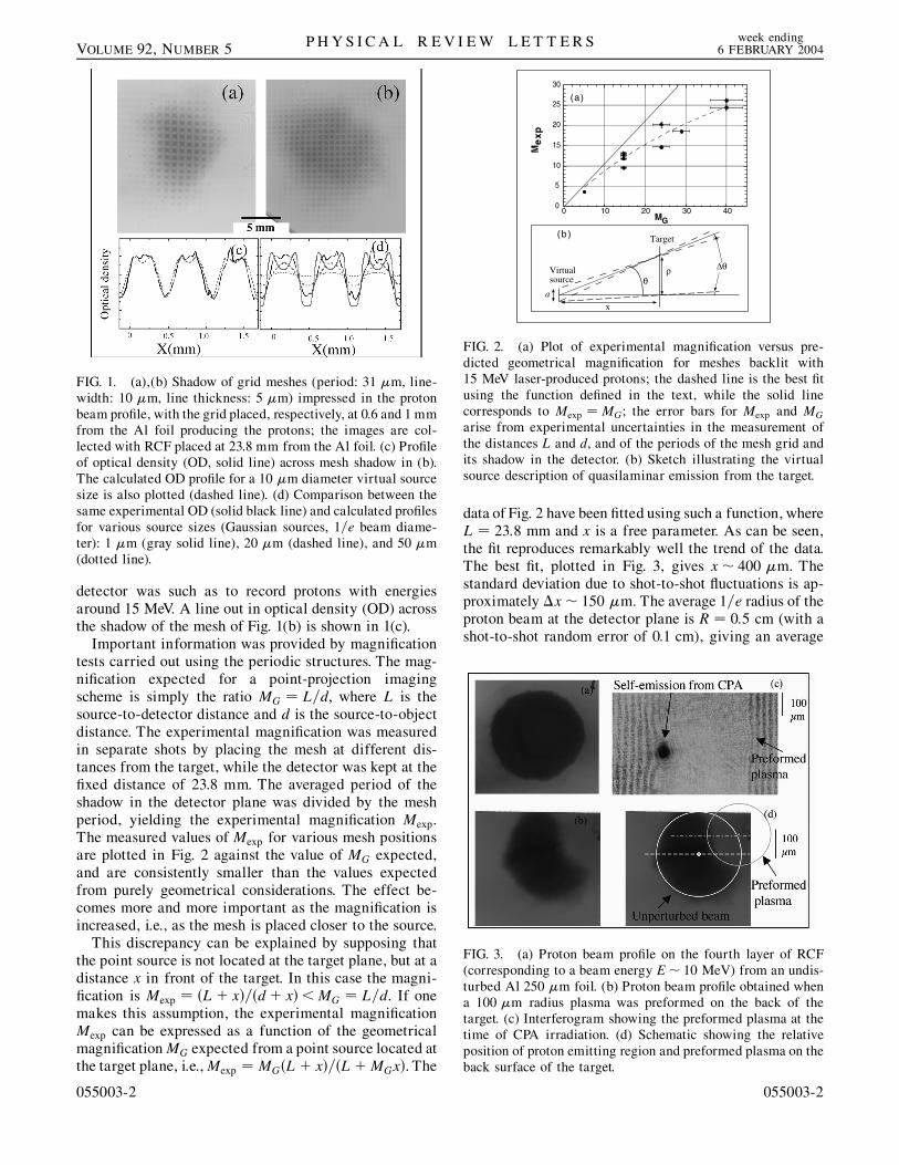
In Fig. 1, shadows of electroformed Cu mesh grids areshown. The meshes are formed by 10 �m lines with31 �m spacing and 5 �m thickness. The mesh was placedparallel to the proton-producing foil at a distance d fromthe foil of 0:6� 0:05 mm in the case of Fig. 2(a) and1:0� 0:05 mm [Fig. 2(b)]. In both cases the RCF layershown was located at a distance L � 23:8� 0:5 mm from
2004 The American Physical Society 055003-1
ρθ
∆θ
x
Virtualsource
Target
0
5
10
15
20
25
30
0 10 20 30 40MG
(a)
(b)
a
Me
xp
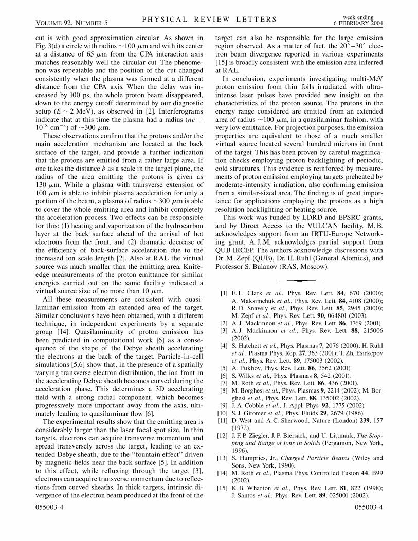
FIG. 2. (a) Plot of experimental magnification versus pre-dicted geometrical magnification for meshes backlit with15 MeV laser-produced protons; the dashed line is the best fitusing the function defined in the text, while the solid linecorresponds to Mexp � MG; the error bars for Mexp and MGarise from experimental uncertainties in the measurement ofthe distances L and d, and of the periods of the mesh grid andits shadow in the detector. (b) Sketch illustrating the virtualsource description of quasilaminar emission from the target.
FIG. 1. (a),(b) Shadow of grid meshes (period: 31 �m, line-width: 10 �m, line thickness: 5 �m) impressed in the protonbeam profile, with the grid placed, respectively, at 0.6 and 1 mmfrom the Al foil producing the protons; the images are col-lected with RCF placed at 23.8 mm from the Al foil. (c) Profileof optical density (OD, solid line) across mesh shadow in (b).The calculated OD profile for a 10 �m diameter virtual sourcesize is also plotted (dashed line). (d) Comparison between thesame experimental OD (solid black line) and calculated profilesfor various source sizes (Gaussian sources, 1=e beam diame-ter): 1 �m (gray solid line), 20 �m (dashed line), and 50 �m(dotted line).
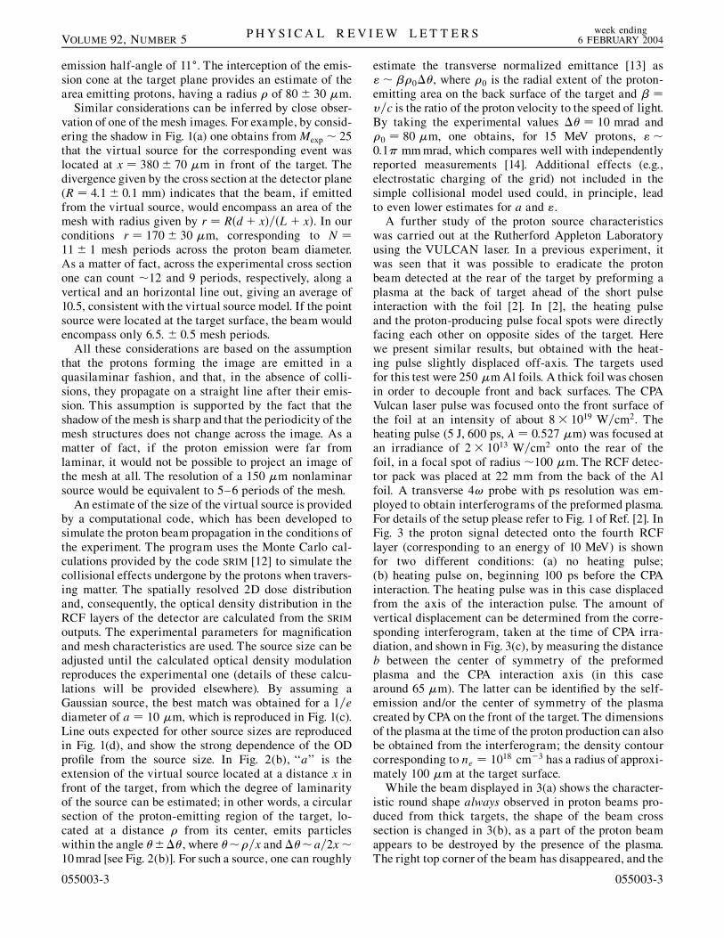
FIG. 3. (a) Proton beam profile on the fourth layer of RCF(corresponding to a beam energy E� 10 MeV) from an undis-turbed Al 250 �m foil. (b) Proton beam profile obtained whena 100 �m radius plasma was preformed on the back of thetarget. (c) Interferogram showing the preformed plasma at thetime of CPA irradiation. (d) Schematic showing the relativeposition of proton emitting region and preformed plasma on theback surface of the target.
P H Y S I C A L R E V I E W L E T T E R S week ending6 FEBRUARY 2004VOLUME 92, NUMBER 5
detector was such as to record protons with energiesaround 15 MeV. A line out in optical density (OD) acrossthe shadow of the mesh of Fig. 1(b) is shown in 1(c).
Important information was provided by magnificationtests carried out using the periodic structures. The mag-nification expected for a point-projection imagingscheme is simply the ratio MG � L=d, where L is thesource-to-detector distance and d is the source-to-objectdistance. The experimental magnification was measuredin separate shots by placing the mesh at different dis-tances from the target, while the detector was kept at thefixed distance of 23.8 mm. The averaged period of theshadow in the detector plane was divided by the meshperiod, yielding the experimental magnification Mexp.The measured values of Mexp for various mesh positionsare plotted in Fig. 2 against the value of MG expected,and are consistently smaller than the values expectedfrom purely geometrical considerations. The effect be-comes more and more important as the magnification isincreased, i.e., as the mesh is placed closer to the source.
This discrepancy can be explained by supposing thatthe point source is not located at the target plane, but at adistance x in front of the target. In this case the magni-fication is Mexp � �L� x�=�d� x�<MG � L=d. If onemakes this assumption, the experimental magnificationMexp can be expressed as a function of the geometricalmagnification MG expected from a point source located atthe target plane, i.e., Mexp � MG�L� x�=�L�MGx�. The
055003-2
data of Fig. 2 have been fitted using such a function, whereL � 23:8 mm and x is a free parameter. As can be seen,the fit reproduces remarkably well the trend of the data.The best fit, plotted in Fig. 3, gives x� 400 �m. Thestandard deviation due to shot-to-shot fluctuations is ap-proximately �x� 150 �m. The average 1=e radius of theproton beam at the detector plane is R � 0:5 cm (with ashot-to-shot random error of 0.1 cm), giving an average
055003-2
P H Y S I C A L R E V I E W L E T T E R S week ending6 FEBRUARY 2004VOLUME 92, NUMBER 5
emission half-angle of 11�. The interception of the emis-sion cone at the target plane provides an estimate of thearea emitting protons, having a radius � of 80� 30 �m.
Similar considerations can be inferred by close obser-vation of one of the mesh images. For example, by consid-ering the shadow in Fig. 1(a) one obtains from Mexp � 25that the virtual source for the corresponding event waslocated at x � 380� 70 �m in front of the target. Thedivergence given by the cross section at the detector plane(R � 4:1� 0:1 mm) indicates that the beam, if emittedfrom the virtual source, would encompass an area of themesh with radius given by r � R�d� x�=�L� x�. In ourconditions r � 170� 30 �m, corresponding to N �11� 1 mesh periods across the proton beam diameter.As a matter of fact, across the experimental cross sectionone can count �12 and 9 periods, respectively, along avertical and an horizontal line out, giving an average of10.5, consistent with the virtual source model. If the pointsource were located at the target surface, the beam wouldencompass only 6:5:� 0:5 mesh periods.
All these considerations are based on the assumptionthat the protons forming the image are emitted in aquasilaminar fashion, and that, in the absence of colli-sions, they propagate on a straight line after their emis-sion. This assumption is supported by the fact that theshadow of the mesh is sharp and that the periodicity of themesh structures does not change across the image. As amatter of fact, if the proton emission were far fromlaminar, it would not be possible to project an image ofthe mesh at all. The resolution of a 150 �m nonlaminarsource would be equivalent to 5–6 periods of the mesh.
An estimate of the size of the virtual source is providedby a computational code, which has been developed tosimulate the proton beam propagation in the conditions ofthe experiment. The program uses the Monte Carlo cal-culations provided by the code SRIM [12] to simulate thecollisional effects undergone by the protons when travers-ing matter. The spatially resolved 2D dose distributionand, consequently, the optical density distribution in theRCF layers of the detector are calculated from the SRIM
outputs. The experimental parameters for magnificationand mesh characteristics are used. The source size can beadjusted until the calculated optical density modulationreproduces the experimental one (details of these calcu-lations will be provided elsewhere). By assuming aGaussian source, the best match was obtained for a 1=ediameter of a � 10 �m, which is reproduced in Fig. 1(c).Line outs expected for other source sizes are reproducedin Fig. 1(d), and show the strong dependence of the ODprofile from the source size. In Fig. 2(b), ‘‘a’’ is theextension of the virtual source located at a distance x infront of the target, from which the degree of laminarityof the source can be estimated; in other words, a circularsection of the proton-emitting region of the target, lo-cated at a distance � from its center, emits particleswithin the angle ����, where ���=x and ���a=2x�10mrad [see Fig. 2(b)]. For such a source, one can roughly
055003-3
estimate the transverse normalized emittance [13] as"� ��0��, where �0 is the radial extent of the proton-emitting area on the back surface of the target and � �v=c is the ratio of the proton velocity to the speed of light.By taking the experimental values �� � 10 mrad and�0 � 80 �m, one obtains, for 15 MeV protons, "�0:1� mmmrad, which compares well with independentlyreported measurements [14]. Additional effects (e.g.,electrostatic charging of the grid) not included in thesimple collisional model used could, in principle, leadto even lower estimates for a and ".
A further study of the proton source characteristicswas carried out at the Rutherford Appleton Laboratoryusing the VULCAN laser. In a previous experiment, itwas seen that it was possible to eradicate the protonbeam detected at the rear of the target by preforming aplasma at the back of target ahead of the short pulseinteraction with the foil [2]. In [2], the heating pulseand the proton-producing pulse focal spots were directlyfacing each other on opposite sides of the target. Herewe present similar results, but obtained with the heat-ing pulse slightly displaced off-axis. The targets usedfor this test were 250 �m Al foils. A thick foil was chosenin order to decouple front and back surfaces. The CPAVulcan laser pulse was focused onto the front surface ofthe foil at an intensity of about 8� 1019 W=cm2. Theheating pulse (5 J, 600 ps, � � 0:527 �m) was focused atan irradiance of 2� 1013 W=cm2 onto the rear of thefoil, in a focal spot of radius �100 �m. The RCF detec-tor pack was placed at 22 mm from the back of the Alfoil. A transverse 4! probe with ps resolution was em-ployed to obtain interferograms of the preformed plasma.For details of the setup please refer to Fig. 1 of Ref. [2]. InFig. 3 the proton signal detected onto the fourth RCFlayer (corresponding to an energy of 10 MeV) is shownfor two different conditions: (a) no heating pulse;(b) heating pulse on, beginning 100 ps before the CPAinteraction. The heating pulse was in this case displacedfrom the axis of the interaction pulse. The amount ofvertical displacement can be determined from the corre-sponding interferogram, taken at the time of CPA irra-diation, and shown in Fig. 3(c), by measuring the distanceb between the center of symmetry of the preformedplasma and the CPA interaction axis (in this casearound 65 �m). The latter can be identified by the self-emission and/or the center of symmetry of the plasmacreated by CPA on the front of the target. The dimensionsof the plasma at the time of the proton production can alsobe obtained from the interferogram; the density contourcorresponding to ne � 1018 cm3 has a radius of approxi-mately 100 �m at the target surface.
While the beam displayed in 3(a) shows the character-istic round shape always observed in proton beams pro-duced from thick targets, the shape of the beam crosssection is changed in 3(b), as a part of the proton beamappears to be destroyed by the presence of the plasma.The right top corner of the beam has disappeared, and the
055003-3
P H Y S I C A L R E V I E W L E T T E R S week ending6 FEBRUARY 2004VOLUME 92, NUMBER 5
cut is with good approximation circular. As shown inFig. 3(d) a circle with radius �100 �m and with its centerat a distance of 65 �m from the CPA interaction axismatches reasonably well the circular cut. The phenome-non was repeatable and the position of the cut changedconsistently when the plasma was formed at a differentdistance from the CPA axis. When the delay was in-creased by 100 ps, the whole proton beam disappeared,down to the energy cutoff determined by our diagnosticsetup (E� 2 MeV), as observed in [2]. Interferogramsindicate that at this time the plasma had a radius (ne �1018 cm3) of �300 �m.
These observations confirm that the protons and/or themain acceleration mechanism are located at the backsurface of the target, and provide a further indicationthat the protons are emitted from a rather large area. Ifone takes the distance b as a scale in the target plane, theradius of the area emitting the protons is given as130 �m. While a plasma with transverse extension of100 �m is able to inhibit plasma acceleration for only aportion of the beam, a plasma of radius �300 �m is ableto cover the whole emitting area and inhibit completelythe acceleration process. Two effects can be responsiblefor this: (1) heating and vaporization of the hydrocarbonlayer at the back surface ahead of the arrival of hotelectrons from the front, and (2) dramatic decrease ofthe efficiency of back-surface acceleration due to theincreased ion scale length [2]. Also at RAL the virtualsource was much smaller than the emitting area. Knife-edge measurements of the proton emittance for similarenergies carried out on the same facility indicated avirtual source size of no more than 10 �m.
All these measurements are consistent with quasi-laminar emission from an extended area of the target.Similar conclusions have been obtained, with a differenttechnique, in independent experiments by a separategroup [14]. Quasilaminarity of proton emission hasbeen predicted in computational work [6] as a conse-quence of the shape of the Debye sheath acceleratingthe electrons at the back of the target. Particle-in-cellsimulations [5,6] show that, in the presence of a spatiallyvarying transverse electron distribution, the ion front inthe accelerating Debye sheath becomes curved during theacceleration phase. This determines a 3D acceleratingfield with a strong radial component, which becomesprogressively more important away from the axis, ulti-mately leading to quasilaminar flow [6].
The experimental results show that the emitting area isconsiderably larger than the laser focal spot size. In thintargets, electrons can acquire transverse momentum andspread transversely across the target, leading to an ex-tended Debye sheath, due to the ‘‘fountain effect’’ drivenby magnetic fields near the back surface [5]. In additionto this effect, while refluxing through the target [3],electrons can acquire transverse momentum due to reflec-tions from curved sheaths. In thick targets, intrinsic di-vergence of the electron beam produced at the front of the
055003-4
target can also be responsible for the large emissionregion observed. As a matter of fact, the 20� –30� elec-tron beam divergence reported in various experiments[15] is broadly consistent with the emission area inferredat RAL.
In conclusion, experiments investigating multi-MeVproton emission from thin foils irradiated with ultra-intense laser pulses have provided new insight on thecharacteristics of the proton source. The protons in theenergy range considered are emitted from an extendedarea of radius �100 �m, in a quasilaminar fashion, withvery low emittance. For projection purposes, the emissionproperties are equivalent to those of a much smallervirtual source located several hundred microns in frontof the target. This has been proven by careful magnifica-tion checks employing proton backlighting of periodic,cold structures. This evidence is reinforced by measure-ments of proton emission employing targets preheated bymoderate-intensity irradiation, also confirming emissionfrom a similar-sized area. The finding is of great impor-tance for applications employing the protons as a highresolution backlighting or heating source.
This work was funded by LDRD and EPSRC grants,and by Direct Access to the VULCAN facility. M. B.acknowledges support from an IRTU-Europe Network-ing grant. A. J. M. acknowledges partial support fromQUB IRCEP. The authors acknowledge discussions withDr. M. Zepf (QUB), Dr. H. Ruhl (General Atomics), andProfessor S. Bulanov (RAS, Moscow).
[1] E. L. Clark et al., Phys. Rev. Lett. 84, 670 (2000);A. Maksimchuk et al., Phys. Rev. Lett. 84, 4108 (2000);R. D. Snavely et al., Phys. Rev. Lett. 85, 2945 (2000);M. Zepf et al., Phys. Rev. Lett. 90, 064801 (2003).
[2] A. J. Mackinnon et al., Phys. Rev. Lett. 86, 1769 (2001).[3] A. J. Mackinnon et al., Phys. Rev. Lett. 88, 215006
(2002).[4] S. Hatchett et al., Phys. Plasmas 7, 2076 (2000); H. Ruhl
et al., Plasma Phys. Rep. 27, 363 (2001); T. Zh. Esirkepovet al., Phys. Rev. Lett. 89, 175003 (2002).
[5] A. Pukhov, Phys. Rev. Lett. 86, 3562 (2001).[6] S. Wilks et al., Phys. Plasmas 8, 542 (2001).[7] M. Roth et al., Phys. Rev. Lett. 86, 436 (2001).[8] M. Borghesi et al., Phys. Plasmas 9, 2214 (2002); M. Bor-
ghesi et al., Phys. Rev. Lett. 88, 135002 (2002).[9] J. A. Cobble et al., J. Appl. Phys. 92, 1775 (2002).
[10] S. J. Gitomer et al., Phys. Fluids 29, 2679 (1986).[11] D. West and A. C. Sherwood, Nature (London) 239, 157
(1972).[12] J. F. P. Ziegler, J. P. Biersack, and U. Littmark, The Stop-
ping and Range of Ions in Solids (Pergamon, New York,1996).
[13] S. Humpries, Jr., Charged Particle Beams (Wiley andSons, New York, 1990).
[14] M. Roth et al., Plasma Phys. Controlled Fusion 44, B99(2002).
[15] K. B. Wharton et al., Phys. Rev. Lett. 81, 822 (1998);J. Santos et al., Phys. Rev. Lett. 89, 025001 (2002).
055003-4