Embed Size (px)
Citation preview
Multi-rotors Flight Controller
M
V1.00
2015.5.4 User Manual
Thanks for your purchase of Tarot professional aerial photography products 。To ensure your success with this product, we would like to introduce the foll-owing information and important notes ,hope it can be useful for you 。
www.tarotrc.com
PMU-5V
LED/OSD
DATA/USB GIMBAL
DSM1 DSM2
S3
S2
S1
M8
M7
M6
M5
M4
M3
M2
M1
AUX
CH1
CH2
CH3
CH4
CH5
CH6
CH7
CH8
CH9
GPS
M
POWER IN
OUT 12v
OUT 5v
PMU
M Multi-rotors Flight Controller Assembly Section
Contents
Disclaimer................................................................2.
Contents............................................................1
Mounting................................................................ .3
Package Contents..........................................................3
Wiring...................................................................4-5
Assistant Software Setup...............................................6
1. Drive & Assistant Software Installation...............................6.
2. Assistant Software Setup..........................................7
Recommended Gains..................................................7
Basic Flight..........................................................8
1. Control Mode...................................................9
2. Turn On or Turn Off the Motor.......................................9
3. Compass Calibration............................................10
4. Check the mounting.............................................11
5. Check before flight..............................................11
6. Flight Test Procedures...........................................11
Advanced Function..................................................12
1. Failsafe......................................................13
2. Low Voltage Protection..........................................14
3. One Motor Fail Protection........................................15
4. Intelligent Orientation Control(IOC).......................................................16
5. Flight Limits...................................................17
LED Indicators............................................................17
LED Indicators Priority:.................................................18
Abnormal LED Indicators Descriptions & Solutions:.......................18
Troubleshooting.....................................................19
1. Abnormal Motor Solutions........................................19
2. Flight Control Mode Changes When GPS DATA Are Abnormal............19
3. Parameters Cannot Be Modified in PC Assistant Software...............19
4.Attentions during Flight..........................................19
Specifications.......................................................20
Disclaimer
2
Please carefully read this statement before using the product. Once using the
product, you agree to and accept this statement. This product is not designed for pe-
ople under 18.
ZYX-M is a flight control system specially designed for multi-rotors enthusiasts.
With attitude stabilization, altitude holding, position locking and autopilotfunctions,
it can be widely applied to various entertainments, aerial photography and FPV activi-
ties. We strongly recommend you to remove all the propellers during upgrading and
parameters setup, ensure all the connections are correct and keep the aircraft far away
from the crowd, the vulnerable and dangerous goods. Tarot accepts no liability directly
or indirectly for the personal injuries and property loss caused by the conditions below:
1. Damages or injuries incurred when users are drunk, taking drugs, drug anesthesia,
dizzy, feeble, nausea and any other mental or physical discomfort.
2. Damages or injuries caused by subjective intentional operations of users.
3. Damages or injuries caused by the failure to follow the guidance of the user manual.
4. Damages or injuries caused by refit or replacement of non-Tarot accessories or com-
ponents.
5. Damages or injuries caused by products of third party or fake.
6. Damages or injuries caused by misoperation or misjudgement.
7. Damages or injuries caused by the internal abrasion, erosion or aging.
8. Damages or injuries caused by continued flying under abnormal alarm.
9. Damages or injuries caused by being aware of flying under abnormal conditions.
10. Damages or injuries caused by flying in magnetic-interference zone, radio-interfer-
ence zone, no-fly zone or poor-sight zone.
11.Damages or injuries caused by bad weather.
12. Damages or injuries caused by crash, capsizing, fire, explosion, thunderstrike,
storm, flood, tsunami, land subsidence, avalanche, earthquake or some other
disastrous accidents.
13. Damages or injuries caused by infringement of data, audio or video materials re-
corded by the aircraft.
14. Damages or injuries caused by misuse of battery.
15. Damages or injuries caused by misuse of users.
16. Other conditions that are not covered by the range of liability of Tarot.
M Multi-rotors Flight Controller Assembly Section
3
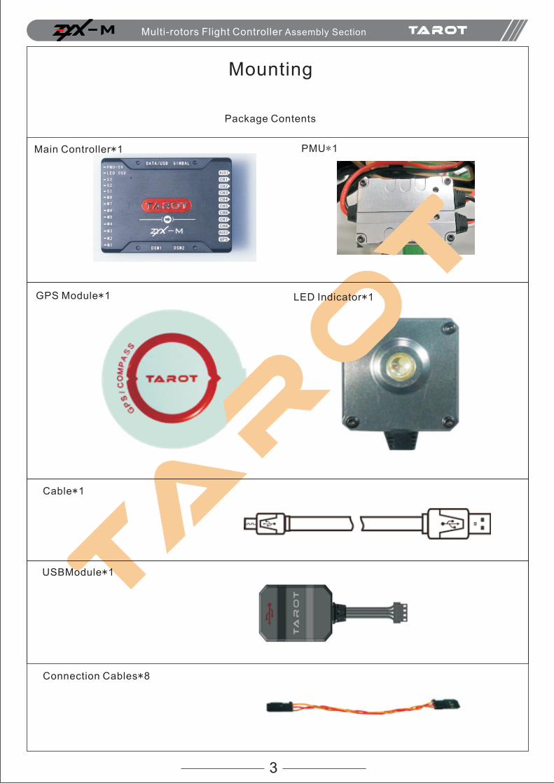
Mounting
Package Contents
Main Controller*1 PMU*1
GPS Module*1 LED Indicator*1
Cable*1
USBModule*1
Connection Cables*8
M Multi-rotors Flight Controller Assembly Section
Wiring
4
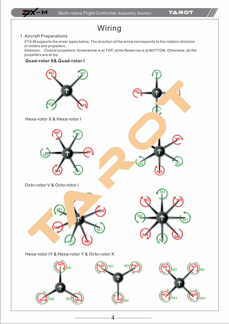
1. Aircraft Preparations
ZYX-M supports the mixer types below. The direction of the arrow corresponds to the rotation direction
of motors and propellers.
Attention: Coaxial propellers: Greenarrow is at TOP, while Redarrow is at BOTTOM. Otherwise, all the
propellers are at top.
Hexa-rotor X & Hexa-rotor I
Octo-rotor V & Octo-rotor I
Hexa-rotor IY & Hexa-rotor Y & Octo-rotor X
M Multi-rotors Flight Controller Assembly Section
Quad-rotor X& Quad-rotor I
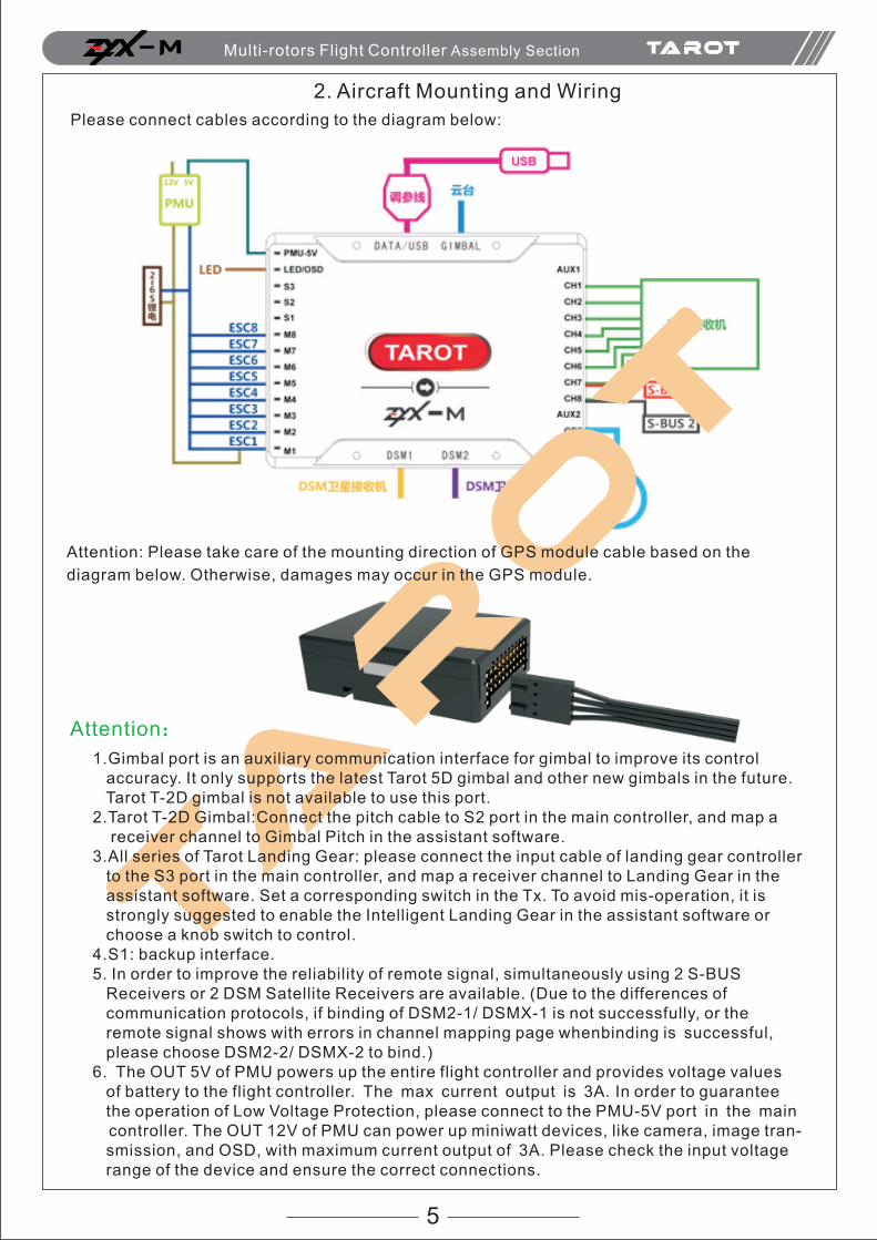
2. Aircraft Mounting and Wiring
5
Please connect cables according to the diagram below:
Attention: Please take care of the mounting direction of GPS module cable based on the
diagram below. Otherwise, damages may occur in the GPS module.
Attention:
M Multi-rotors Flight Controller Assembly Section
1.Gimbal port is an auxiliary communication interface for gimbal to improve its control accuracy. It only supports the latest Tarot 5D gimbal and other new gimbals in the future. Tarot T-2D gimbal is not available to use this port. 2.Tarot T-2D Gimbal:Connect the pitch cable to S2 port in the main controller, and map a receiver channel to Gimbal Pitch in the assistant software. 3.All series of Tarot Landing Gear: please connect the input cable of landing gear controller to the S3 port in the main controller, and map a receiver channel to Landing Gear in the assistant software. Set a corresponding switch in the Tx. To avoid mis-operation, it is strongly suggested to enable the Intelligent Landing Gear in the assistant software or choose a knob switch to control.4.S1: backup interface.5. In order to improve the reliability of remote signal, simultaneously using 2 S-BUS Receivers or 2 DSM Satellite Receivers are available. (Due to the differences of communication protocols, if binding of DSM2-1/ DSMX-1 is not successfully, or the remote signal shows with errors in channel mapping page whenbinding is successful, please choose DSM2-2/ DSMX-2 to bind.)6. The OUT 5V of PMU powers up the entire flight controller and provides voltage values of battery to the flight controller. The max current output is 3A. In order to guarantee the operation of Low Voltage Protection, please connect to the PMU-5V port in the main controller. The OUT 12V of PMU can power up miniwatt devices, like camera, image tran- smission, and OSD, with maximum current output of 3A. Please check the input voltage range of the device and ensure the correct connections.
Assistance Software Setup
6
1)Please download the drive and assistant software from Tarot official website:
http://www.0577mx.com/
2)Run the drive installation program and follow the instruction to finish the procedures.
Choose a corresponding drive file according to your PC system. Currently, we only
support W indows System.
Doubel-Click folder;
Windows ×86
Windows ×64
1.Drive & Assistant Software Installation
2.Assistant Software Setup
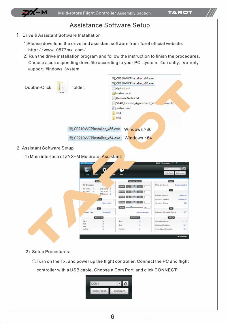
1) Main interface of ZYX-M Multirotor Assistant:
2) Setup Procedures:
M Multi-rotors Flight Controller Assembly Section
①Turn on the Tx, and power up the flight controller. Connect the PC and flight
controller with a USB cable. Choose a Com Port and click CONNECT:
7
2) When“ ”shows on the bottom right corner, it indicates flight controller has
successfully connected to the PC; if it shows“ ”,please re-check the
connections, power supply,USB module drive and the antivirus program in the PC.
DO NOT disconnect the connection during setup.
3) Click “ ” to finish parameters setup, and set more functions in the “ “,
page. Once a parameter has been changed, you should press the “ENTER” key to
send data to flight controller. When all the parameters have been modified,
click “ ” to save these modifications. When “ ” shows on the
bottom left corner, setup procedure finishes. Otherwise, flight controller cannot
save these parameters.
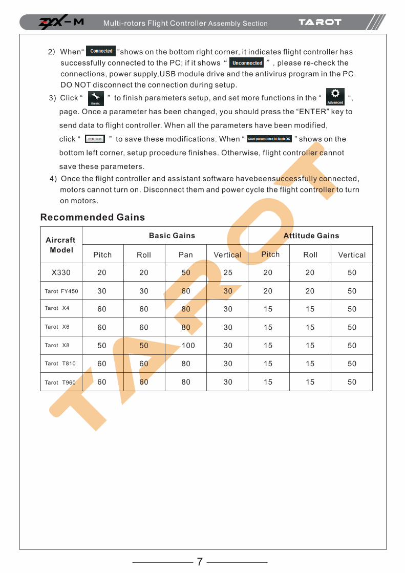
Recommended Gains
Aircraft
Model
X330 20
30
60
60
50
60
60
20
30
60
60
50
60
60
50
60
80
80
100
80
80
25
30
30
30
30
30
30
20
20
15
15
15
15
15
20
20
15
15
15
15
15
50
50
50
50
50
50
50
Tarot FY450
Tarot X4
Tarot X6
Tarot X8
Tarot T810
Tarot T960
Basic Gains Attitude Gains
Pitch Roll Pan Vertical Pitch Roll Vertical
M Multi-rotors Flight Controller Assembly Section
4) Once the flight controller and assistant software havebeensuccessfully connected,
motors cannot turn on. Disconnect them and power cycle the flight controller to turn
on motors.
8
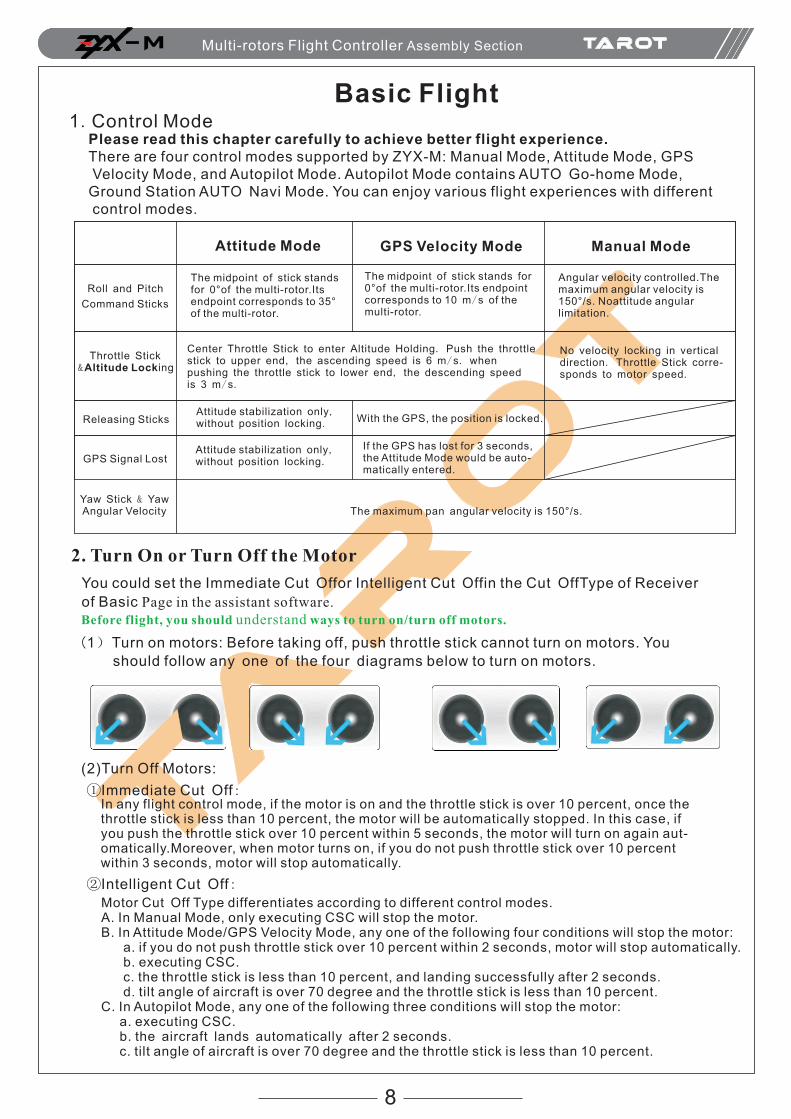
Basic Flight1.Control Mode
Please read this chapter carefully to achieve better flight experience.There are four control modes supported by ZYX-M: Manual Mode, Attitude Mode, GPS Velocity Mode, and Autopilot Mode. Autopilot Mode contains AUTO Go-home Mode, Ground Station AUTO Navi Mode. You can enjoy various flight experiences with different control modes.
Attitude Mode GPS Velocity Mode Manual Mode
The midpoint of stick stands for 0°of the multi-rotor.Its endpoint corresponds to 35°of the multi-rotor.
Center Throttle Stick to enter Altitude Holding. Push the throttle stick to upper end, the ascending speed is 6 m/s. when pushing the throttle stick to lower end, the descending speed is 3 m/s.
The midpoint of stick stands for 0°of the multi-rotor.Its endpoint corresponds to 10 m/s of the multi-rotor.
Angular velocity controlled.The maximum angular velocity is 150°/s. Noattitude angular limitation.
No velocity locking in vertical direction. Throttle Stick corre-sponds to motor speed.
Attitude stabilization only, without position locking.
Attitude stabilization only, without position locking.
With the GPS, the position is locked.
If the GPS has lost for 3 seconds, the Attitude Mode would be auto-matically entered.
The maximum pan angular velocity is 150°/s.Yaw Stick & Yaw Angular Velocity
GPS Signal Lost
Releasing Sticks
Throttle Stick &Altitude Locking
Roll and Pitch
Command Sticks
2. Turn On or Turn Off the Motor
You could set the Immediate Cut Offor Intelligent Cut Offin the Cut OffType of Receiver
of Basic Page in the assistant software. Before flight, you should understand ways to turn on/turn off motors.
(1)Turn on motors: Before taking off, push throttle stick cannot turn on motors. You
should follow any one of the four diagrams below to turn on motors.
(2)Turn Off Motors:
①Immediate Cut Off:In any flight control mode, if the motor is on and the throttle stick is over 10 percent, once the throttle stick is less than 10 percent, the motor will be automatically stopped. In this case, if you push the throttle stick over 10 percent within 5 seconds, the motor will turn on again aut-omatically.Moreover, when motor turns on, if you do not push throttle stick over 10 percent within 3 seconds, motor will stop automatically.
②Intelligent Cut Off:
M Multi-rotors Flight Controller Assembly Section
Motor Cut Off Type differentiates according to different control modes. A. In Manual Mode, only executing CSC will stop the motor. B. In Attitude Mode/GPS Velocity Mode, any one of the following four conditions will stop the motor: a. if you do not push throttle stick over 10 percent within 2 seconds, motor will stop automatically. b. executing CSC. c. the throttle stick is less than 10 percent, and landing successfully after 2 seconds. d. tilt angle of aircraft is over 70 degree and the throttle stick is less than 10 percent.C. In Autopilot Mode, any one of the following three conditions will stop the motor: a. executing CSC. b. the aircraft lands automatically after 2 seconds. c. tilt angle of aircraft is over 70 degree and the throttle stick is less than 10 percent.
9
Attentions for Intelligent Mode
ATTENTIONS:
(1) In Attitude Mode/GPS Velocity Mode/Autopilot Mode, when the aircraft lands, the motor will stop automatically.
(2) In Attitude Mode/GPS Velocity Mode, if you do not push the throttle stick over 10 percent after executing CSC
to turn on the motor, flight controller will enter landing procedures, and the motor will stop after 2 seconds.
(3) During normal flight, only push throttle stick to less than 10 percent will not stop the motor.
(4) In Attitude Mode/GPS Velocity Mode/Autopilot Mode, for safety, when tilt angle of aircraft is over 70 degree
and the throttle stick is less than 10 percent, the motor will stop automatically.
1. If you choose Immediate Cut Off in the assistant software, please do not push throttle stick less
than 10 percent during flight. Otherwise, the motor will stop. If you indeliberately push the
throttle stick toless than 10 percent, please push throttle stick to over 10 percent within 5 seconds.
2. DO NOT execute CSC during flight, because it will lead to the immediate stop of motor.
3. If you choose Immediate Cut Offin the assistant software, in Attitude Mode/GPS Velocity Mode,
once the throttle stick is less than 10 percent, the system will stop and pitch roll &yawsticks lose
control, with control only in throttle stick. Moreover, the aircraft will keep balance and decline
vertically in 3m/s until landing or the throttle stick is over 10 percent again.
4. During flight, no matter in any control mode, we do not suggest you to push throttle stick to less
than 10 percent.
5. If you want these two cut off types work properly, please correctly calibrate the Tx.
6. Executing CSC will be blocked by the main controller during Failsafe, and the motor will ma-
intain the status before.
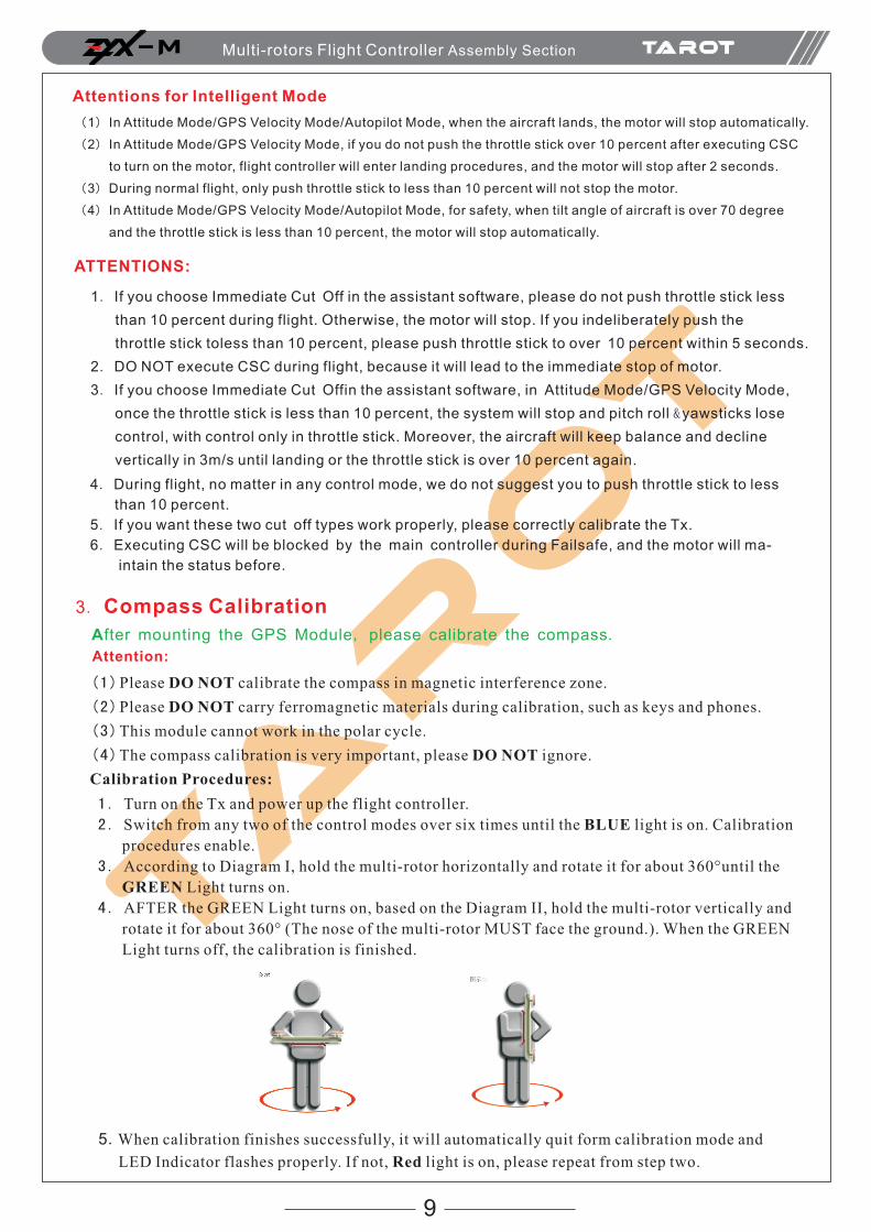
3. Compass Calibration
After mounting the GPS Module, please calibrate the compass.
Attention:
(1)Please DO NOT calibrate the compass in magnetic interference zone.
(2)Please DO NOT carry ferromagnetic materials during calibration, such as keys and phones.
(3)This module cannot work in the polar cycle.
(4)The compass calibration is very important, please DO NOT ignore.
Calibration Procedures:
1. Turn on the Tx and power up the flight controller.
2. Switch from any two of the control modes over six times until the BLUE light is on. Calibration
procedures enable.
3. According to Diagram I, hold the multi-rotor horizontally and rotate it for about 360°until the
GREEN Light turns on.
4. AFTER the GREEN Light turns on, based on the Diagram II, hold the multi-rotor vertically and
rotate it for about 360° (The nose of the multi-rotor MUST face the ground.). When the GREEN
Light turns off, the calibration is finished.
5.When calibration finishes successfully, it will automatically quit form calibration mode and
LED Indicator flashes properly. If not, Red light is on, please repeat from step two.
M Multi-rotors Flight Controller Assembly Section
10
Attention:
(1) When compass data is abnormal, RED light of LED Indicatorturns on andGPS turns off.
Attitude Mode enables.
(2) The aircraft do not need to be rotated for 360° horizontally or vertically with precision.
(3) If calibration procedures fail several times, please check the magnetic interference around.
(4) You should calibrate the compass in the following circumstances:
a、Flight location changes;
b、Mechanical structure of aircraft changes:
Mounting position of GPS module changes;
Electronic devices add/remove/reposition, such as main controller, servo and battery;
c、Drifts happen and the aircraft cannot fly in a straight line.
4. Check the mountingPlease read the following MISTAKES carefully. Any one of these mistakes may lead to serious accidents.
(1)Motor rotates in the opposite direction. (2)Connection cablesof motors and ESCs are not reliable.(3)The mounting direction of main controller does not match the setting direction in the software, or the mounting is not firm;(4)Wrong/unfirm connections between ESCs and main controller.(5)Wrong rotation direction of propellers;(6)Magnetization of the compass.
Attention:Please ensure:
(1)Correctly mount the multi-rotor;
(2)Properly set all the parameters in the assistant software;
(3)All the wirings and connections work normally;
(4)The power supply of Tx, main controller and other components are in great condition
5. Check before flightThe following procedures are based on the Intelligent Cut OffMode. Check the status of your
aircraft with procedures below. Please refer to Chapter LED IndicatorDescriptionfor more
information.
1. Turn on the Tx, then power up the aircraft.
2. Keep the aircraft stationary after 5 seconds when the flight controller powers up.
As it enters initialization, LED lights flash in turn.
(Attention:when the BLUE light is on, please DO NOT move the aircraft, Tx switches, or sticks. Otherwise,
initializationerrors may occur.)
( )。
When the BLUE light turns off, toggle the switch of control mode on the Tx to observe the LED Indicator.
If LED light flash like it indicates the current control mode is Attitude Mode and
GPS Satellite data are not available. )
3. When 6 or more GPS Satellites have been found for the first time, Purple Light flashes for 20 times.
Chart for the corresponding LED lights of Manual Mode, Attitude Mode, and GPS Velocity
Mode (with GPS module):
(1) GPS Satellite Indicator is ,which indicates the satellite data are not available.
(2) With GPS module, GPS Satellite Indicator flashes after Control Mode lights.
Manual Mode Signal is great (GPS Satellite >6)
Attitude Mode Signal is well (GPS Satellite =6)
GPS Velocity Mode Signal is bad (GPS Satellite =5)
Autopilot Mode Signal is worst (GPS Satellite <5)
GPS Module Data is not available.
no light no light
(DO NOT fly in this condition)
(DO NOT fly in this condition)
M Multi-rotors Flight Controller Assembly Section

11
4. Toggle the switch of control mode on the Tx to Attitude Mode, and keep the aircraft stationary. Execute any one of the CSC to turn on the motor:
5. After turning on the motor, center the roll/pitch/yaw sticks immediately, and keep the throttle stick under midpoint. Observe the rotation direction of propellers. 6.Execute CSC to stop the motor and power off the aircraft.7. Please ensure all the above steps are correct before entering flight test. * If other LED Indicator flashes after powering up, please refer to Chapter LED Indicator for further information.
6. Flight Test Procedures
1. Choose an open space without any obstruction and the crowd. Put the aircraft on a level ground at least 3 meters far away from you.2. In GPS Velocity Mode, please wait until enough GPS satellites have been found (RED light flashes once or not). With Attitude/Manual Mode, it need not wait for GPS satellites. Manual Mode is only recomme- nded to experts. 3. Procedures:(1) Turn on the Tx, then power up the aircraft. Keep the aircraft stationary and wait for the initialization and self-check. (2) After the aircraft self-check and BLUE light turns off, execute CSC to turn on the motor.(3) After turning on the motor, center the roll/pitch/yaw sticks, and move the throttle stick from the bottom. (If the throttle stick does not move from the bottom, the motor will stop; if the motor s tops, restart the procedure from step one.)(4) Push the throttle stick over the midpoint, and the aircraft will take off from the ground. (DO NOT push too hard, in case o f taking off too fast.)(5) Observe the movement of aircraft and toggle sticks to adjust. (6) When reaching the ideal altitude, you could center the throttle stick, and keep the pitch/roll/yaw stick at midpoint. The aircraft will hover.4. Gradually decline the aircraft. Do not land it on the hard object. Move the throttle stick to the bottom and execute CSC to stop the motor. 5. Power off the aircraft, then turn off the Tx. Flight test finishes.
Attention!!!DO NOT:
(1) If you choose Immediate Cut Off in the assistant software, please do not push throttle stick to less than 10
percent during flight. Otherwise, the motor will stop. If you indeliberately push the throttle stick less than
10 percent, please push throttle stick to 10 percent within 5 seconds.
(2)DO NOT execute CSC during flight. Otherwise, the motor will stop.
(3)Please take care of the GPS Satellite LED Light during flight and ensure it on the great or well condition
(no light or )Otherwise, the aircraft will drift during hovering.
(4) DO NOT fly in the magnetic interference area. Ferromagnetic materials would affect inside magnetic sensor.
(5)DO NOT choose GPS Velocity Mode in the area with weak GPS signal.
(6) If Low Voltage Alarm occurs with RED light flashing, please land the aircraft as soon as possible.
(7) If Low Voltage Alarm happens on the Tx, please land the aircraft as soon as possible.
(8)With GPS Velocity Mode, please record the home-point when the GPS signal is well or great. Otherwise,
the recording may not be accurate.
TIPs:
(1)The midpoint of throttle stick is 0m/s. Please keep it higher than 10 percent during flight.
(2) Take care of the landing speed when landing. Decline gradually can avoid damages as much
as possible.
(3) Once the aircraft enters Failsafe, the aircraft would fly according to your settings in the
assistant software.
(4) Once the aircraft enters Low Battery Protection, the aircraft would fly according to your
settings in the assistant software.
M Multi-rotors Flight Controller Assembly Section
12
Advanced Function1. Failsafe
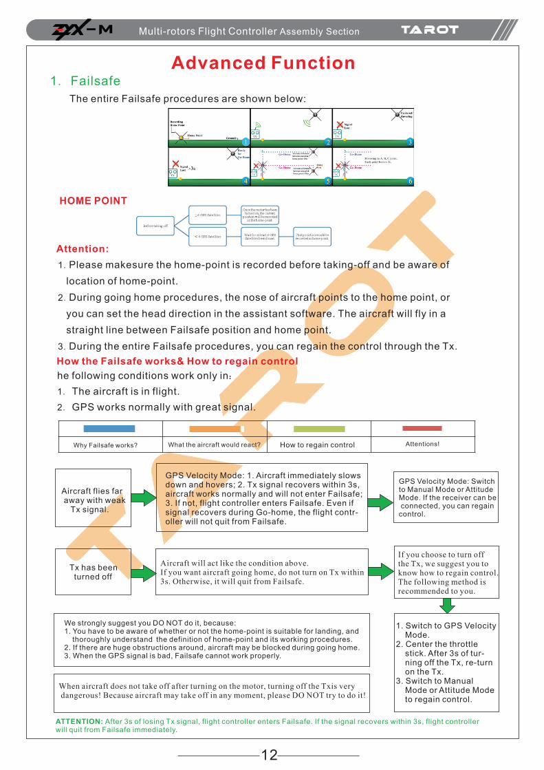
The entire Failsafe procedures are shown below:
Attention:
1.Please makesure the home-point is recorded before taking-off and be aware of
location of home-point.
2.During going home procedures, the nose of aircraft points to the home point, or
you can set the head direction in the assistant software. The aircraft will fly in a
straight line between Failsafe position and home point.
3.During the entire Failsafe procedures, you can regain the control through the Tx.
How the Failsafe works& How to regain control
he following conditions work only in:
1. The aircraft is in flight.
2. GPS works normally with great signal.
Why Failsafe works? What the aircraft would react? How to regain control Attentions!
Aircraft flies far away with weak Tx signal.
GPS Velocity Mode: 1. Aircraft immediately slows down and hovers; 2. Tx signal recovers within 3s, aircraft works normally and will not enter Failsafe; 3. If not, flight controller enters Failsafe. Even if signal recovers during Go-home, the flight contr-oller will not quit from Failsafe.
GPS Velocity Mode: Switch to Manual Mode or Attitude Mode. If the receiver can be connected, you can regain control.
Tx has been turned off
Aircraft will act like the condition above.If you want aircraft going home, do not turn on Tx within3s. Otherwise, it will quit from Failsafe.
If you choose to turn off the Tx, we suggest you to know how to regain control. The following method is recommended to you.
1. Switch to GPS Velocity Mode.2. Center the throttle stick. After 3s of tur- ning off the Tx, re-turn on the Tx.3. Switch to Manual Mode or Attitude Mode to regain control.
We strongly suggest you DO NOT do it, because:1. You have to be aware of whether or not the home-point is suitable for landing, and thoroughly understand the definition of home-point and its working procedures.2. If there are huge obstructions around, aircraft may be blocked during going home.3. When the GPS signal is bad, Failsafe cannot work properly.
When aircraft does not take off after turning on the motor, turning off the Txis very dangerous! Because aircraft may take off in any moment, please DO NOT try to do it!
ATTENTION: After 3s of losing Tx signal, flight controller enters Failsafe. If the signal recovers within 3s, flight controller will quit from Failsafe immediately.
M Multi-rotors Flight Controller Assembly Section
HOME POINT
13
AUTO Go-home Mode
When AUTO Go-home Mode is on, the flight path of aircraft is as same as the Failsafe Go-home path.If you want the aircraft going home, please DO NOT switch to other control mode during flight.
When AUTO Go-home Mode is on, Go-home switch would disable. If aircraft lands automatically or sw-itches to a different control mode during flight, you can regain control again (quit f rom AUTO Go-home Mode).
Attention: AUTO Go-home only enables in GPS Velocity Mode.
2. Low Voltage ProtectionWe design two levels of low voltage protection to avoid accidents. We strongly recommend you to
turn on this function in the assistant software. When the voltage is too low, low voltage protection
works to protect your aircraft from falling down.
There are two levels of voltage protection: First-Level Protection and Second-Level Protection.
When First-Level Protection has been entered, Yellow Light flashes quickly for warning. During
Second-Level Protection, Red Light flashes quickly and the aircraft gradually declines. If you
want the aircraft hovering, just push the throttle stick to 90 percent.
Please calibrate the voltage in the assistant
software before enabling this function.
When low voltage alarm enables, please land your aircraft as quickly as possible to avoid
accidents.
Attentions:
Set Low Voltage P rotectioninthe Voltage section in the Advanced Page in the assistant software.
3.One Motor Fail ProtectionFor any kind of Hexa-rotors or Octo-rotors, if one of its motors output has failed, you could still control the Tx to land the aircraft safely.
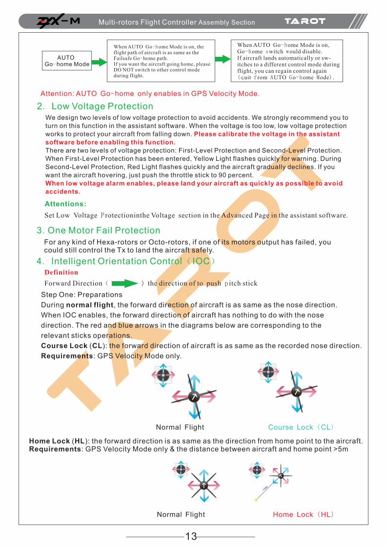
4. Intelligent Orientation Control( IOC)Definition
Forward Direction( )the direction of to push p itch stick
Step One: Preparations
During normal flight, the forward direction of aircraft is as same as the nose direction.
When IOC enables, the forward direction of aircraft has nothing to do with the nose
direction. The red and blue arrows in the diagrams below are corresponding to the
relevant sticks operations.
Course Lock (CL): the forward direction of aircraft is as same as the recorded nose direction.
Requirements: GPS Velocity Mode only.
Normal Flight Course Lock (CL)
Normal Flight Home Lock (HL)
Home Lock (HL): the forward direction is as same as the direction from home point to the aircraft. Requirements: GPS Velocity Mode only & the distance between aircraft and home point >5m
M Multi-rotors Flight Controller Assembly Section
14
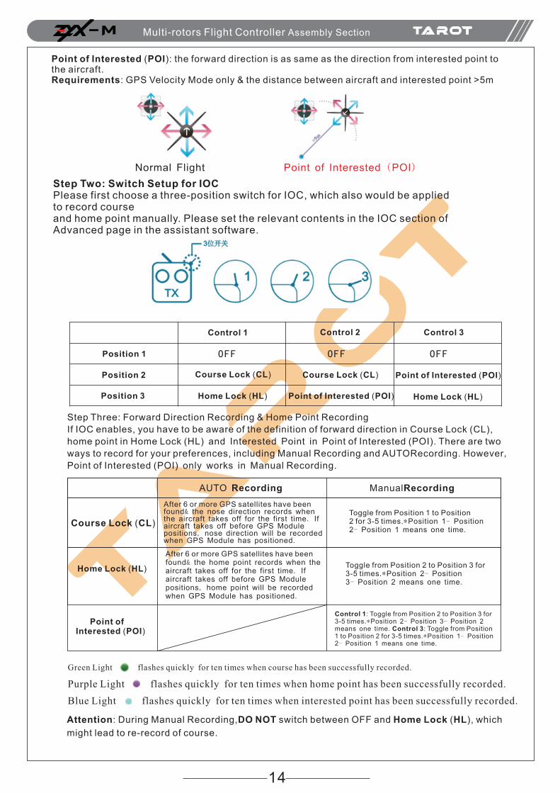
Point of Interested (POI): the forward direction is as same as the direction from interested point tothe aircraft.Requirements: GPS Velocity Mode only & the distance between aircraft and interested point >5m
Normal Flight Point of Interested (POI)
Step Two: Switch Setup for IOCPlease first choose a three-position switch for IOC, which also would be applied to record course and home point manually. Please set the relevant contents in the IOC section of Advanced page in the assistant software.
Control 1
OFF
Course Lock (CL)
Home Lock (HL)Position 3
Position 2
Position 1
Course Lock (CL)
Point of Interested (POI)
Point of Interested (POI)
Home Lock (HL)
OFF OFF
Control 2 Control 3
Step Three: Forward Direction Recording & Home Point Recording
If IOC enables, you have to be aware of the definition of forward direction in Course Lock (CL),
home point in Home Lock (HL) and Interested Point in Point of Interested (POI). There are two
ways to record for your preferences, including Manual Recording and AUTORecording. However,
Point of Interested (POI) only works in Manual Recording.
AUTO Recording ManualRecording
After 6 or more GPS satellites have been found& the nose direction records when the aircraft takes off for the first time. If aircraft takes off before GPS Module positions, nose direction will be recorded when GPS Module has positioned.
Toggle from Position 1 to Position 2 for 3-5 times.*Position 1- Position 2- Position 1 means one time.
After 6 or more GPS satellites have been found& the home point records when the aircraft takes off for the first time. If aircraft takes off before GPS Module positions, home point will be recorded when GPS Module has positioned.
Toggle from Position 2 to Position 3 for 3-5 times.*Position 2- Position 3- Position 2 means one time.
Control 1: Toggle from Position 2 to Position 3 for 3-5 times.*Position 2- Position 3- Position 2 means one time.Control 3: Toggle from Position 1 to Position 2 for 3-5 times.*Position 1- Position2- Position 1 means one time.
Point of Interested (POI)
Home Lock (HL)
Course Lock (CL)
Green Light flashes quickly for ten times when course has been successfully recorded.
Purple Light flashes quickly for ten times when home point has been successfully recorded.
Blue Light flashes quickly for ten times when interested point has been successfully recorded.
Attention: During Manual Recording,DO NOT switch between OFF and Home Lock (HL), which
might lead to re-record of course.
M Multi-rotors Flight Controller Assembly Section
15
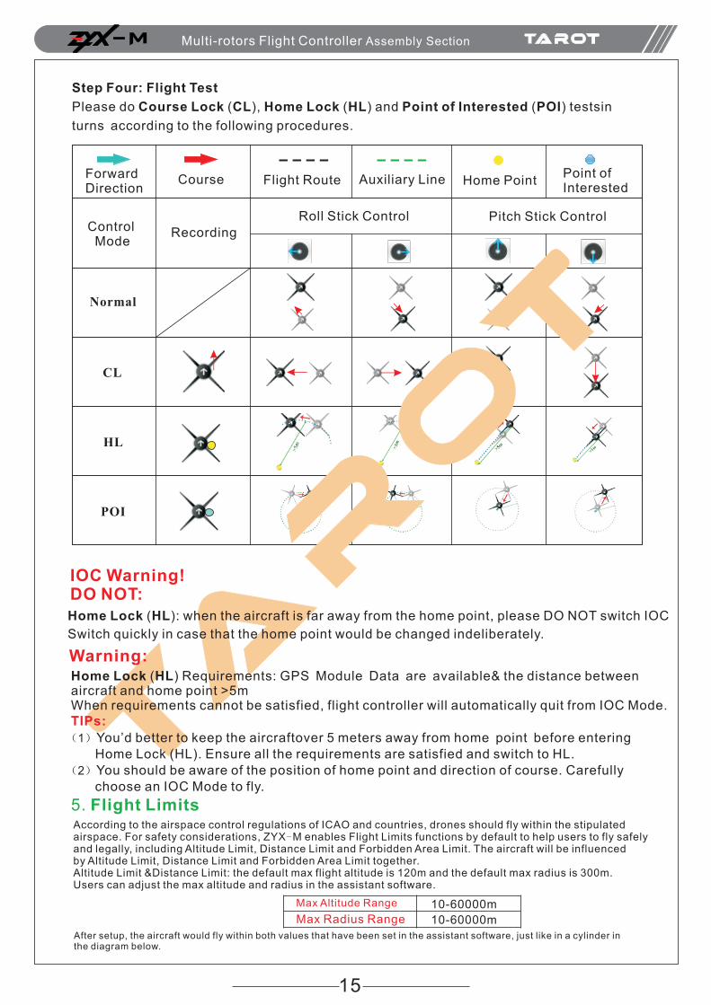
Step Four: Flight Test
Please do Course Lock (CL), Home Lock (HL) and Point of Interested (POI) testsin
turns according to the following procedures.
ForwardDirection
Course Flight Route Auxiliary Line Home PointPoint of Interested
Roll Stick Control Pitch Stick ControlControl Mode
Normal
CL
HL
POI
Recording
IOC Warning!DO NOT:Home Lock (HL): when the aircraft is far away from the home point, please DO NOT switch IOC
Switch quickly in case that the home point would be changed indeliberately.
Warning:Home Lock (HL) Requirements: GPS Module Data are available& the distance between aircraft and home point >5mWhen requirements cannot be satisfied, flight controller will automatically quit from IOC Mode. TIPs:
(1)You’d better to keep the aircraftover 5 meters away from home point before entering Home Lock (HL). Ensure all the requirements are satisfied and switch to HL. (2)You should be aware of the position of home point and direction of course. Carefully choose an IOC Mode to fly.
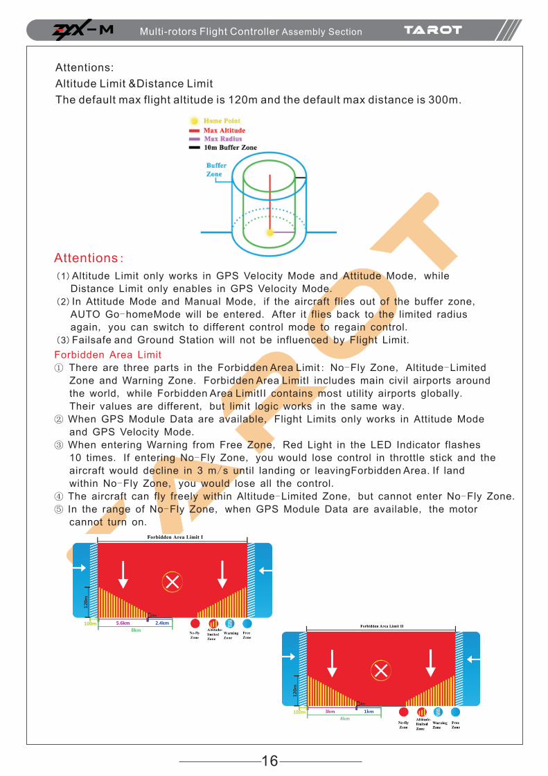
5. Flight LimitsAccording to the airspace control regulations of ICAO and countries, drones should fly within the stipulated airspace. For safety considerations, ZYX-M enables Flight Limits functions by default to help users to fly safely and legally, including Altitude Limit, Distance Limit and Forbidden Area Limit. The aircraft will be influenced by Altitude Limit, Distance Limit and Forbidden Area Limit together. Altitude Limit &Distance Limit: the default max flight altitude is 120m and the default max radius is 300m.Users can adjust the max altitude and radius in the assistant software.
M Multi-rotors Flight Controller Assembly Section
After setup, the aircraft would fly within both values that have been set in the assistant software, just like in a cylinder in the diagram below.
Max Altitude Range 10-60000m
10-60000mMax Radius Range
16
Attentions:
Altitude Limit &Distance Limit
The default max flight altitude is 120m and the default max distance is 300m.
Attentions:
(1)
(2)
(3)
Altitude Limit only works in GPS Velocity Mode and Attitude Mode, while
Distance Limit only enables in GPS Velocity Mode.
In Attitude Mode and Manual Mode, if the aircraft flies out of the buffer zone,
AUTO Go-homeMode will be entered. After it flies back to the limited radius
again, you can switch to different control mode to regain control.
Failsafe and Ground Station will not be influenced by Flight Limit.
Forbidden Area Limit
①
②
③
④
⑤
There are three parts in the Forbidden Area Limit: No-Fly Zone, Altitude-Limited
Zone and Warning Zone. Forbidden Area LimitI includes main civil airports around
the world, while Forbidden Area LimitII contains most utility airports globally.
Their values are different, but limit logic works in the same way.
When GPS Module Data are available, Flight Limits only works in Attitude Mode
and GPS Velocity Mode.
When entering Warning from Free Zone, Red Light in the LED Indicator flashes
10 times. If entering No-Fly Zone, you would lose control in throttle stick and the
aircraft would decline in 3 m/s until landing or leavingForbidden Area. If land
within No-Fly Zone, you would lose all the control.
The aircraft can fly freely within Altitude-Limited Zone, but cannot enter No-Fly Zone.
In the range of No-Fly Zone, when GPS Module Data are available, the motor
cannot turn on.
M Multi-rotors Flight Controller Assembly Section
17
Please DO NOT break regulations and laws in your country. Read the airspace control regulations of ICAO and your country carefully. Tarot accepts no liability directly or indi-rectly for the damages or injuries caused by the misuse of the flight limit function guided by this user manual.
Warning:
LED IndicatorsLED Indicators Priority:
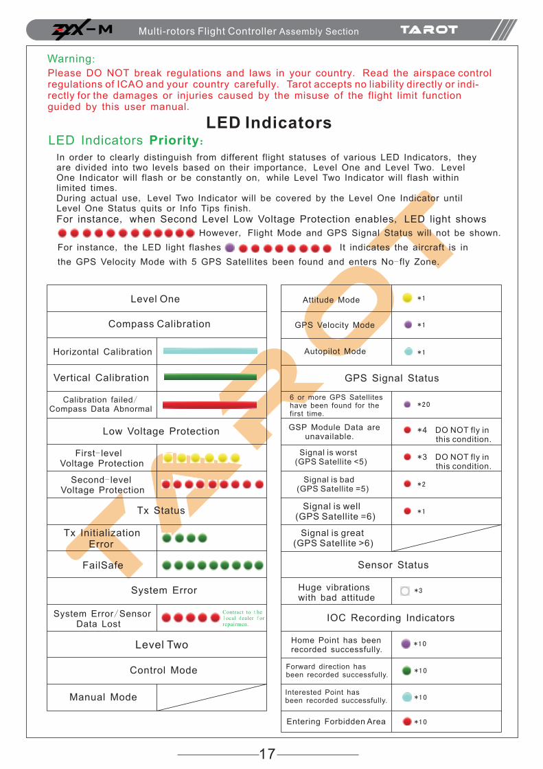
In order to clearly distinguish from different flight statuses of various LED Indicators, they are divided into two levels based on their importance, Level One and Level Two. Level One Indicator will flash or be constantly on, while Level Two Indicator will flash within limited times. During actual use, Level Two Indicator will be covered by the Level One Indicator until Level One Status quits or Info Tips finish.For instance, when Second Level Low Voltage Protection enables, LED light shows
However, Flight Mode and GPS Signal Status will not be shown.
For instance, the LED light flashes It indicates the aircraft is in
the GPS Velocity Mode with 5 GPS Satellites been found and enters No- fly Zone.
Level One
Compass Calibration
Horizontal Calibration
Vertical Calibration
Calibration failed/ Compass Data Abnormal
Low Voltage Protection
First- level Voltage Protection
Second- level Voltage Protection
Tx Status
System Error
Tx Initialization Error
FailSafe
System Error/Sensor Data Lost
Contract to the local dealer for repairmen.
Level Two
Control Mode
Manual Mode
Attitude Mode
GPS Velocity Mode
Autopilot Mode
*1
*1
*1
*20
*4 DO NOT fly in this condition.
*3 DO NOT fly in this condition.
*2
*3
*10
*10
*10
*10
*1
GPS Signal Status
6 or more GPS Satellites have been found for the first time.
GSP Module Data are unavailable.
Signal is worst (GPS Satellite <5)
Signal is bad (GPS Satellite =5)
Signal is well (GPS Satellite =6)
Signal is great (GPS Satellite >6)
Sensor Status
Huge vibrations with bad attitude
IOC Recording Indicators
Home Point has been recorded successfully.
Forward direction has been recorded successfully.
Interested Point has been recorded successfully.
Entering Forbidden Area
M Multi-rotors Flight Controller Assembly Section
18
Abnormal LED Indicators Descriptions & Solutions:
appearance cause solvent
Green Light
flashes slowly a fter a irc-raft powering up.
Tx initialization errorPower cycle. First turn on the Tx and then power up the flight controller.DO NOT touch Tx sticks whenflight controllerinitializes.
Red Light
flashes slowly after aircraft powering up.
Sensor initialization error Contract to the local dealer for repairmen.
Light flashes 3 times quickly during flight.
Huge Vibrations with bad attitude
Land as quickly as possible and find the vibrations.
Red Light is on during flight.
Magnetic field errorLeave current flight area as soon as possible or land.
Green Light flashes
quickly during flight.
Tx Signal Lost
If errors are caused by misoperation, please power cycle the Tx. If Tx battery is low, please change the battery as soon as possible.Attentions: if GPS Module Data are available and the aircraft does not receive the Tx Signal within 3s, Failsafe Mode will be entered.
M Multi-rotors Flight Controller Assembly Section
19
Troubleshooting1. Abnormal Motor Solutions
Motors do not rotate:
①
②
③
Wiring Problem: Please check connections between the main controller, motors with
main controller, and ESCs with motors.
Please check whether or not the motors or ESCs are broken.
In the MOTOR part of ADVANCED page of PC assistant software, increase the Motor
Idle Speed.
Motors rotate in a wrong direction:There are three cables connecting motors and
ESCs. Please exchange any two of them.
2. Flight Control Mode Changes When GPS DATA Are Abnormal.
Attention: during flight, if there is something wrong with GPS data, the flight control
system would change flight mode automatically for safety:
BEFORE GPS data goes wrong AFTER GPS data goes wrong
Attitude Mode Attitude Mode
GPSVelocity Mode Attitude Mode
Manual Mode
Attitude Mode
Manual Mode
Autopilot Mode
3. Parameters Cannot Be Modified in PC Assistant Software
4. Attentions during Flight
Please ensure:
Please ensure that:
Please DO NOT:
①
②
③
④
⑤
You have correctly mounted the multi-rotor;
All the connections and wiring are in great conditions;
All the components have powered up.
The parameters have been correctly set in the assistant software.
GPS signal is great; otherwise, drift might occur during hovering.
①DO NOT fly in strong magnetic area!
②Within the 10 seconds after the system has powered on, please DO NOT move the multi-rotor or sticks. Wait for initialization.
Attentions:
①
②
③
Before taking off, please turn on the transmitter and then power on the multi-rotor;
After landing, please power off the multi-rotor, and then turn off the transmitter.
During flight, if Low Voltage Alarm is on, please land your multi-rotor as quickly
as possible.
①
②
③ ,
"
The main controller and PC assistant software have correctly connected;
”ENTER” key has been c licked a fter modification.
When all the parameters have been modified, click to save these
modifications,and “ shows on the bottom left corner.
M Multi-rotors Flight Controller Assembly Section
20
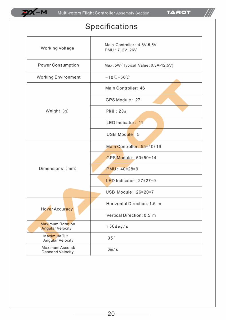
Specifications
Working Voltage
Power Consumption
Main Controller: 4.8V-5.5V
PMU:7.2V-26V
Max:5W(Typical Value:0.3A-12.5V)
Working Environment -10℃-50℃
Weight (g)
Dimensions (mm)
Main Controller: 46
GPS Module: 27
PMU:23g
LED Indicator: 11
USB Module: 5
Main Controller: 55*40*16
GPS Module: 50*50*14
PMU: 40*28*9
LED Indicator: 27*27*9
USB Module: 26*20*7
Horizontal Direction: 1.5 m
Vertical Direction: 0.5 m
150deg/s
35°
6m/s
Hover Accuracy
Maximum Rotation Angular Velocity
Maximum Tilt Angular Velocity
Maximum Ascend/Descend Velocity
M Multi-rotors Flight Controller Assembly Section


![Kakute F4 Flight Controller - · PDF file[Type here] [Type here] Page | 1 Kakute F4 Overview The Holybro Kakute F4 flight controller supports important features of Betaflight/Cleanflight,](https://img.pdfslide.net/doc/110x75/5a9eb19a7f8b9a8e178bb380/kakute-f4-flight-controller-type-here-type-here-page-1-kakute-f4-overview.jpg)