Embed Size (px)
Citation preview
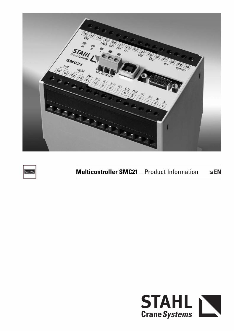
Multicontroller SMC21 _ Product Information

PISM
C21_
02.F
M
2

PISM
C21_
02.F
M
3
Contents
1 Features of the Multicontroller 1.1 Description..................................................................................................................... 41.2 Special features of the Multicontroller..................................................................... 41.3 Description of function ................................................................................................ 51.4 Data security ................................................................................................................. 5
2 Warnings and errors 2.1 Warnings ........................................................................................................................ 82.2 Errors .............................................................................................................................. 9
3 Electrical connection 3.1 Inputs ............................................................................................................................ 103.1.1 Control switch inputs ................................................................................................. 103.1.2 Load signal inputs....................................................................................................... 103.1.3 Temperature inputs .................................................................................................... 113.1.4 Additional functions ................................................................................................... 113.1.5 PC/laptop connection................................................................................................. 113.2 Outputs ......................................................................................................................... 123.2.1 Contact elements for lifting and lowering .............................................................. 123.2.2 -err and -option relays ............................................................................................... 12
4 Mechanical data 4.1 Dimensions .................................................................................................................. 134.2 Methods of attachment ............................................................................................. 134.3 Lead connection ......................................................................................................... 134.4 Terminal allocation ..................................................................................................... 13
5 Technical data 5 Technical data ............................................................................................................ 14
Subject to technical alterations, errors and printing errors excepted
06.08
PISM
C21_
02.F
M
4
1 Features of Multicontroller
1.1 Description • The Multicontroller is a programmable control, evaluation and switching device for single or dual-speed motors. The Multicontroller can be optimally adapted to the application of controlling a hoist motor and provides a compact overall solution.It provides the basis for safe working, long service life and documentation of the actual use of the hoist. With the Multicontroller, STAHL CraneSystems sets a high safety standard for hoists and hoist systems.
1.2 Special features of the Multicontroller
• Constant monitoring of load by overload cut-off even when hoist is at a standstill.• Overload protection by ALC automatic load control (not applicable for frequency
inverter operation)• Load spectrum memory for load-dependent summation of operating time• Temperature control of hoist and travel motors• Registration of operating data, e.g. operating hours, motor switching operations
and load cycles• Various adjustable time functions for motor control, e.g. disabling of inching
operation at slow and fast motor speed• Slack rope cut-off when operated with load suspension equipment• Simple realisation of a second load cut-off point• Simple connection of visual and acoustic transducers• Optional connection of a large-format load display• Optional connection of a display in control pendant• Optional connection of a function display in an HBC radio remote control switch• Tare function for load display• Data exchange with a PC, can be switched between serial RS232 data interface or
USB interface• CAN communication interface is integrated• High data safety thanks to redundant saving of data• Data saving with no-volt protection without back-up battery• LED function display• Activation of crane test possible by pushbutton or PC software• Communication with a HBC radio remote control possible
09.08
PISM
C21_
02.F
M
5
1 Features of Multicontroller
1.3 Description of function 1.3.1 ALC automatic load control
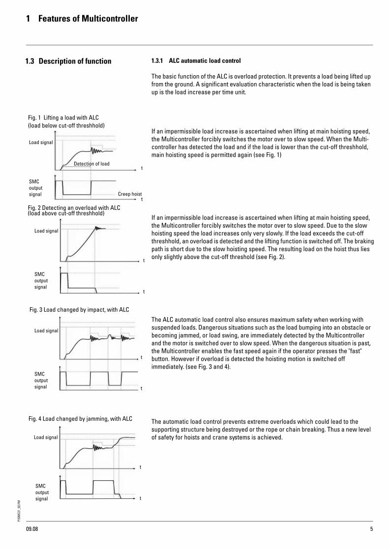
The basic function of the ALC is overload protection. It prevents a load being lifted up from the ground. A significant evaluation characteristic when the load is being taken up is the load increase per time unit.
If an impermissible load increase is ascertained when lifting at main hoisting speed, the Multicontroller forcibly switches the motor over to slow speed. When the Multi-controller has detected the load and if the load is lower than the cut-off threshhold, main hoisting speed is permitted again (see Fig. 1)
If an impermissible load increase is ascertained when lifting at main hoisting speed, the Multicontroller forcibly switches the motor over to slow speed. Due to the slow hoisting speed the load increases only very slowly. If the load exceeds the cut-off threshhold, an overload is detected and the lifting function is switched off. The braking path is short due to the slow hoisting speed. The resulting load on the hoist thus lies only slightly above the cut-off threshold (see Fig. 2).
The ALC automatic load control also ensures maximum safety when working with suspended loads. Dangerous situations such as the load bumping into an obstacle or becoming jammed, or load swing, are immediately detected by the Multicontroller and the motor is switched over to slow speed. When the dangerous situation is past, the Multicontroller enables the fast speed again if the operator presses the "fast" button. However if overload is detected the hoisting motion is switched off immediately. (see Fig. 3 and 4).
The automatic load control prevents extreme overloads which could lead to the supporting structure being destroyed or the rope or chain breaking. Thus a new level of safety for hoists and crane systems is achieved.
Fig. 1 Lifting a load with ALC
Detection of load
Load signal
Creep hoist
SMC
signal
Fig. 2 Detecting an overload with ALC
Load signal
SMC
Fig. 3 Load changed by impact, with ALC
Load signal
SMC
Load signal
SMC
Fig. 4 Load changed by jamming, with ALC
outputsignal
outputsignal
outputsignal
output
t
t
t
t
t
t
t
t
(load below cut-off threshhold)
(load above cut-off threshhold)
09.08

PISM
C21_
02.F
M
6
1 Features of Multicontroller
1.3.2 Temperature controlMonitoring of the hoist motor is standard. If a ptc thermistor reacts this is displayed by LEDs on the Multicontroller and the load cannot be moved again until the hoist motor has cooled off.Various forms of inching operation (fast speed, change of direction) can be disabled by the programmable time functions in the Multicontroller. This prevents the motor heating up quickly thus affording reliable protection against overheating.As an option, a second ptc thermistor can be connected (e.g. temperature pre-warning). This temperature input can also be used for monitoring the temperature of the travel motor. It is output via travel motor output right/left and can also be output by the "option" relay contact. The assignment of the outputs and inputs is determined when configuring the Multicontroller (chapter 3.1.3)
1.3.3 Slack rope cut-offIn certain applications, it is necessary to detect when the load is set down or the load removed from the rope. When this occurs no further lowering must take place. The slack rope function causes the lowering motion to be switched off as soon as the Multicontroller has detected that the rope is free of load. The hoist can then only be moved in upwards direction. To enable the slack rope function, a constant dead-weight is necessary, such as is the case in grab operation (adjustable from 5-30%). The accuracy of the cut-off depends on the load sensor used. The slack rope cut-off is automatically deactivated if the load sensor signal is outside its range. It is possi-ble to deactivate the slack rope function by a signal at the Multicontroller input (chapter 3.1.4).
1.3.4 Load spectrumThe Multicontroller records the actual use of the hoist as per FEM 9.755 failsafe. The full load hours and thus the remaining service life are calculated from the data recorded, taking into account load, operating time and hoisting speed. When the limit value for the load spectrum, determined by the relevant mechanism group as per FEM 9.511 is reached (e.g. 2 m = 1,600 full load hours), it can be displayed on the Multicontroller.
1.3.5 Operating dataApart from the load spectrum value, further important data are metered, saved and calculated in the Multicontroller. The following operating data are recorded separately for slow and fast hoisting speeds:• Total operating hours• Motor switching operations• Duty cycle (DC)• Switching operations per hour (c/h)
In addition, the Multicontroller registers the number of• Overloads• Disconnects due to high temperature• Load cycles and resulting full load cycles• System restarts
This permits the stress on the supporting structures to be calculated. The operating data can be read out with a PC (laptop) as required, evaluated in graphic form, printed and filed. Recording the operating data permits the actual use of the hoist system to be calculated.
06.08
PISM
C21_
02.F
M
7
1 Features of Multicontroller
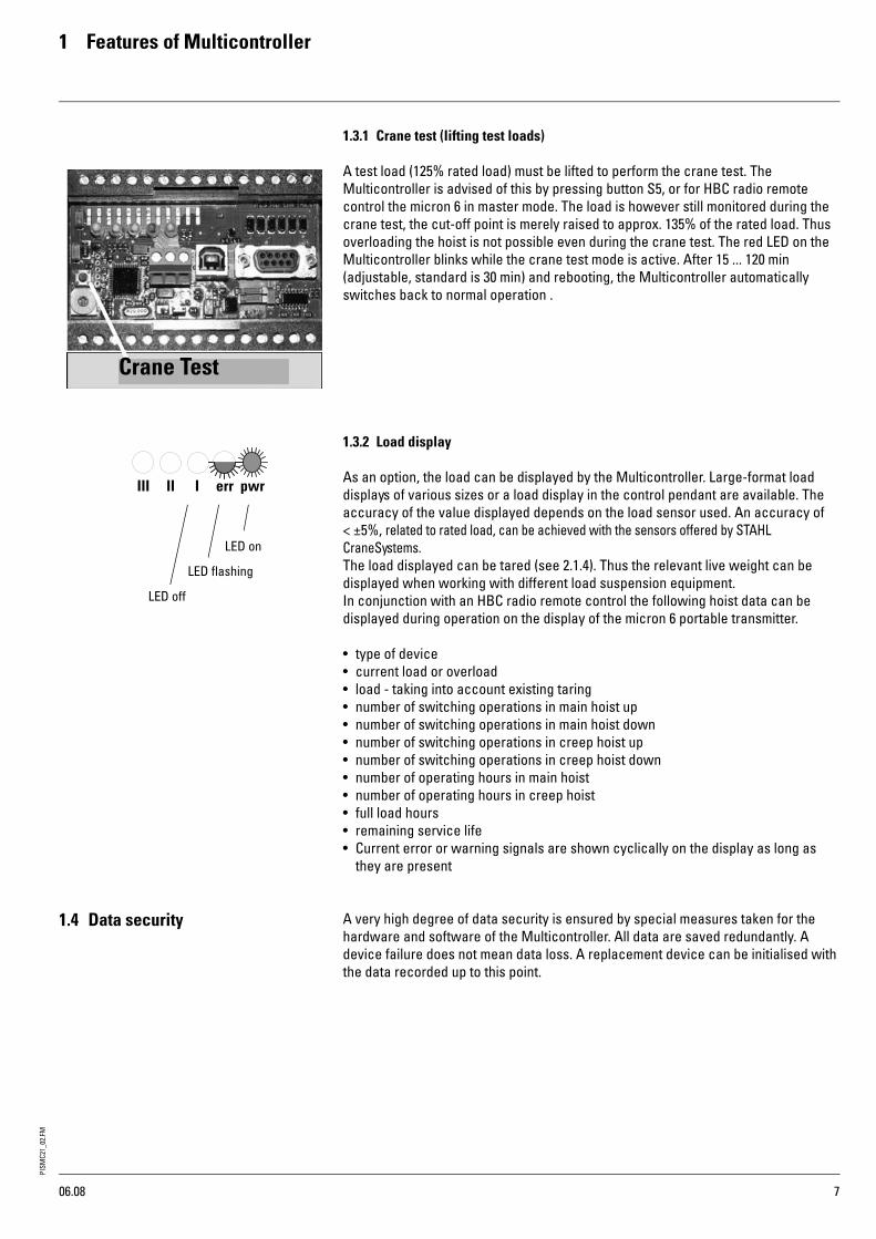
1.3.1 Crane test (lifting test loads)
A test load (125% rated load) must be lifted to perform the crane test. The Multicontroller is advised of this by pressing button S5, or for HBC radio remote control the micron 6 in master mode. The load is however still monitored during the crane test, the cut-off point is merely raised to approx. 135% of the rated load. Thus overloading the hoist is not possible even during the crane test. The red LED on the Multicontroller blinks while the crane test mode is active. After 15 ... 120 min (adjustable, standard is 30 min) and rebooting, the Multicontroller automatically switches back to normal operation .
1.3.2 Load display
As an option, the load can be displayed by the Multicontroller. Large-format load displays of various sizes or a load display in the control pendant are available. The accuracy of the value displayed depends on the load sensor used. An accuracy of < ±5%, related to rated load, can be achieved with the sensors offered by STAHL CraneSystems.The load displayed can be tared (see 2.1.4). Thus the relevant live weight can be displayed when working with different load suspension equipment.In conjunction with an HBC radio remote control the following hoist data can be displayed during operation on the display of the micron 6 portable transmitter.
• type of device• current load or overload• load - taking into account existing taring• number of switching operations in main hoist up• number of switching operations in main hoist down• number of switching operations in creep hoist up• number of switching operations in creep hoist down• number of operating hours in main hoist• number of operating hours in creep hoist• full load hours• remaining service life• Current error or warning signals are shown cyclically on the display as long as
they are present
1.4 Data security A very high degree of data security is ensured by special measures taken for the hardware and software of the Multicontroller. All data are saved redundantly. A device failure does not mean data loss. A replacement device can be initialised with the data recorded up to this point.
Crane Test
LED on
LED flashing
LED off
06.08
PISM
C21_
02.F
M
8
2 Warnings and errors
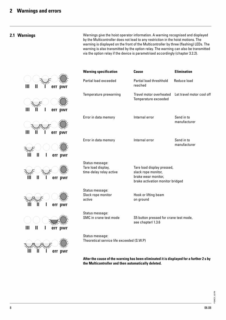
2.1 Warnings Warnings give the hoist operator information. A warning recognised and displayed by the Multicontroller does not lead to any restriction in the hoist motions. The warning is displayed on the front of the Multicontroller by three (flashing) LEDs. The warning is also transmitted by the option relay. The warning can also be transmitted via the option relay if the device is parametrised accordingly (chapter 3.2.2).
Warning specification Cause Elimination
Partial load exceeded Partial load threshhold Reduce loadreached
Temperature prewarning Travel motor overheated Let travel motor cool offTemperature exceeded
Error in data memory Internal error Send in to manufacturer
Error in data memory Internal error Send in to manufacturer
Status message:Tare load display, Tare load display pressed,time-delay relay active slack rope monitor,
brake wear monitor, brake activation monitor bridged
Status message:Slack rope monitor Hook or lifting beam active on ground
Status message:SMC in crane test mode S5 button pressed for crane test mode,
see chapterl 1.3.6
Status message:Theoretical service life exceeded (S.W.P)
After the cause of the warning has been eliminated it is displayed for a further 2 s by the Multicontroller and then automatically deleted.
06.08
PISM
C21_
02.F
M
9
2 Warnings and errors
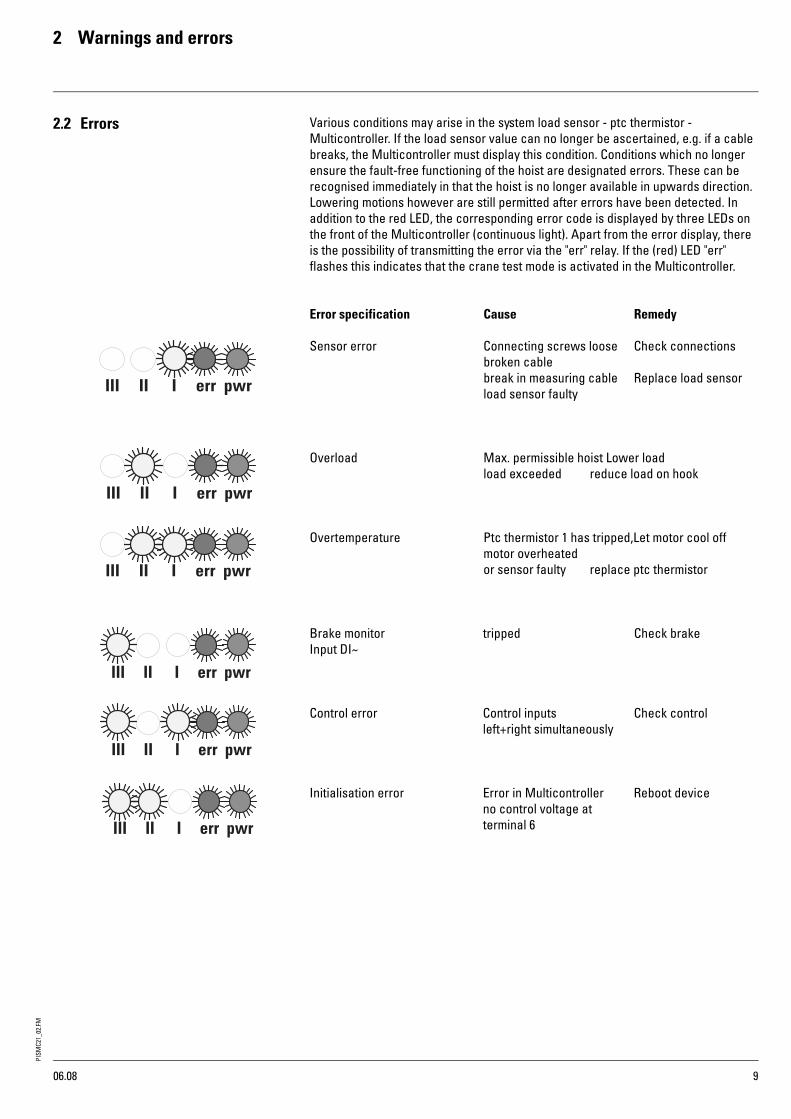
2.2 Errors Various conditions may arise in the system load sensor - ptc thermistor - Multicontroller. If the load sensor value can no longer be ascertained, e.g. if a cable breaks, the Multicontroller must display this condition. Conditions which no longer ensure the fault-free functioning of the hoist are designated errors. These can be recognised immediately in that the hoist is no longer available in upwards direction. Lowering motions however are still permitted after errors have been detected. In addition to the red LED, the corresponding error code is displayed by three LEDs on the front of the Multicontroller (continuous light). Apart from the error display, there is the possibility of transmitting the error via the "err" relay. If the (red) LED "err" flashes this indicates that the crane test mode is activated in the Multicontroller.
Error specification Cause Remedy
Sensor error Connecting screws loose Check connectionsbroken cablebreak in measuring cable Replace load sensorload sensor faulty
Overload Max. permissible hoist Lower loadload exceeded reduce load on hook
Overtemperature Ptc thermistor 1 has tripped,Let motor cool offmotor overheatedor sensor faulty replace ptc thermistor
Brake monitor tripped Check brakeInput DI~
Control error Control inputs Check controlleft+right simultaneously
Initialisation error Error in Multicontroller Reboot deviceno control voltage atterminal 6
06.08
PISM
C21_
02.F
M
10
3 Electrical connection
3.1 Inputs 3.1.1 Control switch inputs
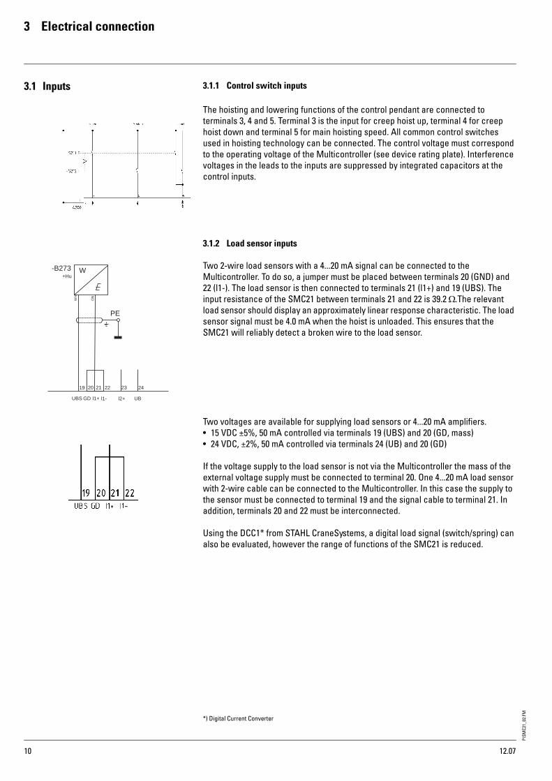
The hoisting and lowering functions of the control pendant are connected to terminals 3, 4 and 5. Terminal 3 is the input for creep hoist up, terminal 4 for creep hoist down and terminal 5 for main hoisting speed. All common control switches used in hoisting technology can be connected. The control voltage must correspond to the operating voltage of the Multicontroller (see device rating plate). Interference voltages in the leads to the inputs are suppressed by integrated capacitors at the control inputs.
3.1.2 Load sensor inputs
Two 2-wire load sensors with a 4...20 mA signal can be connected to the Multicontroller. To do so, a jumper must be placed between terminals 20 (GND) and 22 (l1-). The load sensor is then connected to terminals 21 (l1+) and 19 (UBS). The input resistance of the SMC21 between terminals 21 and 22 is 39.2 Ω.The relevant load sensor should display an approximately linear response characteristic. The load sensor signal must be 4.0 mA when the hoist is unloaded. This ensures that the SMC21 will reliably detect a broken wire to the load sensor.
Two voltages are available for supplying load sensors or 4...20 mA amplifiers.• 15 VDC ±5%, 50 mA controlled via terminals 19 (UBS) and 20 (GD, mass)• 24 VDC, ±2%, 50 mA controlled via terminals 24 (UB) and 20 (GD)
If the voltage supply to the load sensor is not via the Multicontroller the mass of the external voltage supply must be connected to terminal 20. One 4...20 mA load sensor with 2-wire cable can be connected to the Multicontroller. In this case the supply to the sensor must be connected to terminal 19 and the signal cable to terminal 21. In addition, terminals 20 and 22 must be interconnected.
Using the DCC1* from STAHL CraneSystems, a digital load signal (switch/spring) can also be evaluated, however the range of functions of the SMC21 is reduced.
-B273
W
+Hu
PE
2322212019 24
UBS GD l1+ l1- l2+ UB
WH
GN
*) Digital Current Converter
12.07

PISM
C21_
02.F
M
11
3 Electrical connection
3.1.3 Temperature inputs
The hoist motor temperature sensor(s) is/are connected to terminals 16 and 17. If the hoist drive has two temperature controlled hoist motors, both temperature sensors are connected in series. If the hoist motor(s) do/does not have temperature sensors, terminal 16 and 17 must be connected by a resistance of 250 Ω. The values of the temperature sensors to be connected must meet DIN 44 080. A high-ohm input resistance or a short-circuit are recognised as a temperature error and all outputs (7...10) are switched off. After the motor has cooled off the error is automatically acknowledged by the Multicontroller and hoist motions permitted again.
One or more further temperature sensors can be connected to terminals 25, 26 as temperature pre-warning. The values of the temperature sensors to be connected must meet DIN 44 080. A high-ohm input resistance is recognised as pre-warning temperature and treated as a warning by the Multicontroller. After the motor has cooled off the warning is automatically acknowledged by the Multicontroller. The function "temperature control for travel motors" can also be configured and switched to the option relay.This function can also be used as "temperature control for travel motors and swit-ched to the option relay as an option.
3.1.4 Additional functionsAs an alternative, the temperature input terminals 25 and 26 can be used for the following functions:
• overriding the slack rope function, if slack rope function is programmed or taring the load display, i.e. the value 0.00 t appears on the load display
These functions can be parametrised using ConfigTool.
3.1.5 PC/laptop connection
The Multicontroller has a SUB-D9 socket and a USB socket type B on the front for connecting a PC or laptop. The Multicontroller can be parametrised optionally via these two interfaces, i.e. can be switched over via switches.
USB RS232
12.07

PISM
C21_
02.F
M
12
3 Electrical connection
3.2 Outputs 3.2.1 Contact elements for lifting and lowering
• The control voltage for the hoisting and lowering contactors is connected to termi-nal 6
• Terminal 7 is the output for contactor "slow up"• Terminal 8 is the output for contactor "fast up"• Terminal 9 is the output for contactor "slow down" • Terminal 10 is the output for contactor "fast down".
• Rated breaking capacity of relays 250 VAC, 5 A, operating mode AC1
3.2.2 err and -option relaysThe err relay, terminals 27 and 28, is intended for transmitting error signals. The isolated relay output can be connected to a visual or acoustic transducer for remote signalising of system errors. The output types continuous signal or pulse signal are available. It can be configured as normally open or normally closed as required.
The option relay, terminals 29 and 30, is intended for transmitting warning signals. The isolated relay output can be connected to a visual transducer for the remote signalising of warnings (e.g. partial load point exceeded). It can be configured as normally open or normally closed as required.The reaction time and hysteresis of the partial load point can be programmed.
• Rated breaking capacity of relays 250 VAC, 5 A, operating mode AC1
12.07
PISM
C21_
02.F
M
13
4 Mechanical data
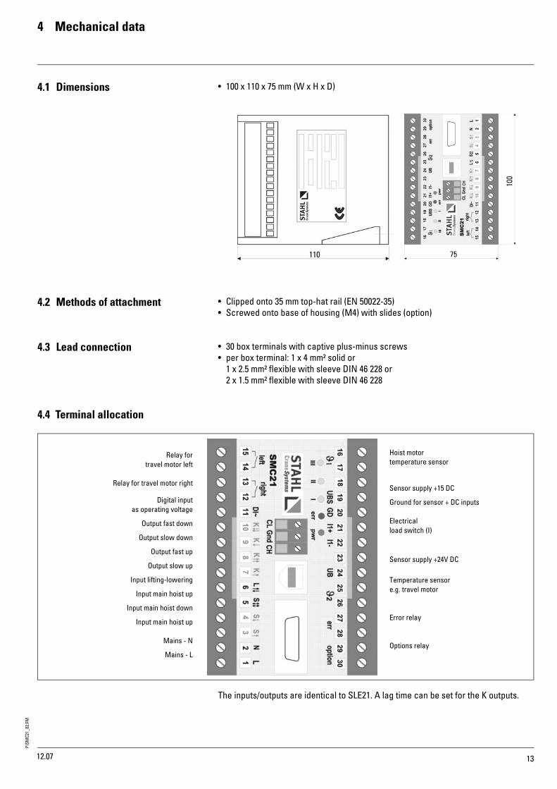
4.1 Dimensions • 100 x 110 x 75 mm (W x H x D)
4.2 Methods of attachment • Clipped onto 35 mm top-hat rail (EN 50022-35)• Screwed onto base of housing (M4) with slides (option)
4.3 Lead connection • 30 box terminals with captive plus-minus screws• per box terminal: 1 x 4 mm² solid or
1 x 2.5 mm² flexible with sleeve DIN 46 228 or 2 x 1.5 mm² flexible with sleeve DIN 46 228
4.4 Terminal allocation
The inputs/outputs are identical to SLE21. A lag time can be set for the K outputs.
Relay fortravel motor left
Relay for travel motor right
Digital inputas operating voltage
Output fast down
Output slow down
Output fast up
Output slow up
Input lifting-lowering
Input main hoist up
Input main hoist down
Input main hoist up
Mains - N
Mains - L
Hoist motor temperature sensor
Sensor supply +15 DC
Ground for sensor + DC inputs
Electricalload switch (I)
Sensor supply +24V DC
Temperature sensore.g. travel motor
Error relay
Options relay
12.07

PISM
C21_
02.F
M
14
5 Technical data
5 Techncal data
Absorbed power < 9 VATemperature range: operation
storage
-40°C ... + 55°C (tandard)-40°C ... + 70°C (optional)-40°C ... + 70°C
Protection type IP 20 EN 60 529EMC EN 61000-6-3 (2001)
EN 61000-6-2 (2001-10)Temperature inputs- Maximum total cold resistance 1500 Ω DIN 0660- Response resistance 2800 Ω ... 3500 Ω- Maximum release resistance 1650 ΩRelay outputs 250 V / 5 A/2A
500 VAContact inputs < 10 mADigital input IN (18) 24 VDCConnection terminals Box terminals for max. 2x1.5 mm² with sleeveAttachment Top-hat rail EN 50022 TS35 or with screwsWeight 0.5 kgSoftwareLED display Pwr Err III II I
} Coded warning or error number
Operating voltages-10 ... + 15%, 50/60 Hz
24 VDC24 VAC42 VAC48 VAC110/120 VAC230 VAC
Sensor supply UB (24) UBS (19)
24 VDC15 VDCtotal < 50 mA
Sensor inputs (analog) 2-wire 4-wire
R in = 39.2 Ω; 0 ... 25 mA
Accuracy ± 1 % of final value
12.07

PISM
C21_
02.F
M
15
Vertriebspartnersales partner
Tochtergesellschaftsubsidiary
Europe T F E
Austria Steyregg +43 732 641111-0 +43 732 641111-33 [email protected]
France Paris +33 1 39985060 +33 1 34111818 [email protected]
Great Britain Birmingham +44 121 7676414 +44 121 7676490 [email protected]
Italy S. Colombano +39 0185 358391 +39 0185 358219 [email protected]
Netherlands EL Haarlem +31 23 51252-20 +31 23 51252-23 [email protected]
Portugal Lissabon +351 21 44471-61 +351 21 44471-69 [email protected]
Spain Madrid +34 91 484-0865 +34 91 490-5143 [email protected]
Switzerland Däniken +41 62 82513-80 +41 62 82513-81 [email protected]
America/Asia T F E
China Shanghai +86 21 6257 2211 +86 21 6254 1907 [email protected]
India Chennai +91 44 4352-3955 +91 44 4352-3957 [email protected]
Singapore Singapore +65 6271 2220 +65 6377 1555 [email protected]
U.A.E. Dubai +971 4 805-3700 +971 4 805-3701 [email protected]
USA Charleston, SC +1 843 767-1951 +1 843 767-4366 [email protected]
F-PI
-5.1
-EN
-09.
08-m
p
STAHL CraneSystems GmbH, Daimlerstr. 6, 74653 Künzelsau, GermanyTel +49 7940 128-0, Fax +49 7940 55665, [email protected]