Embed Size (px)
Citation preview
Multiplexed
Micromegas for
muographySIMON BOUTEILLE
CEA/Irfu/SPhN
The Micromegas Detector
2
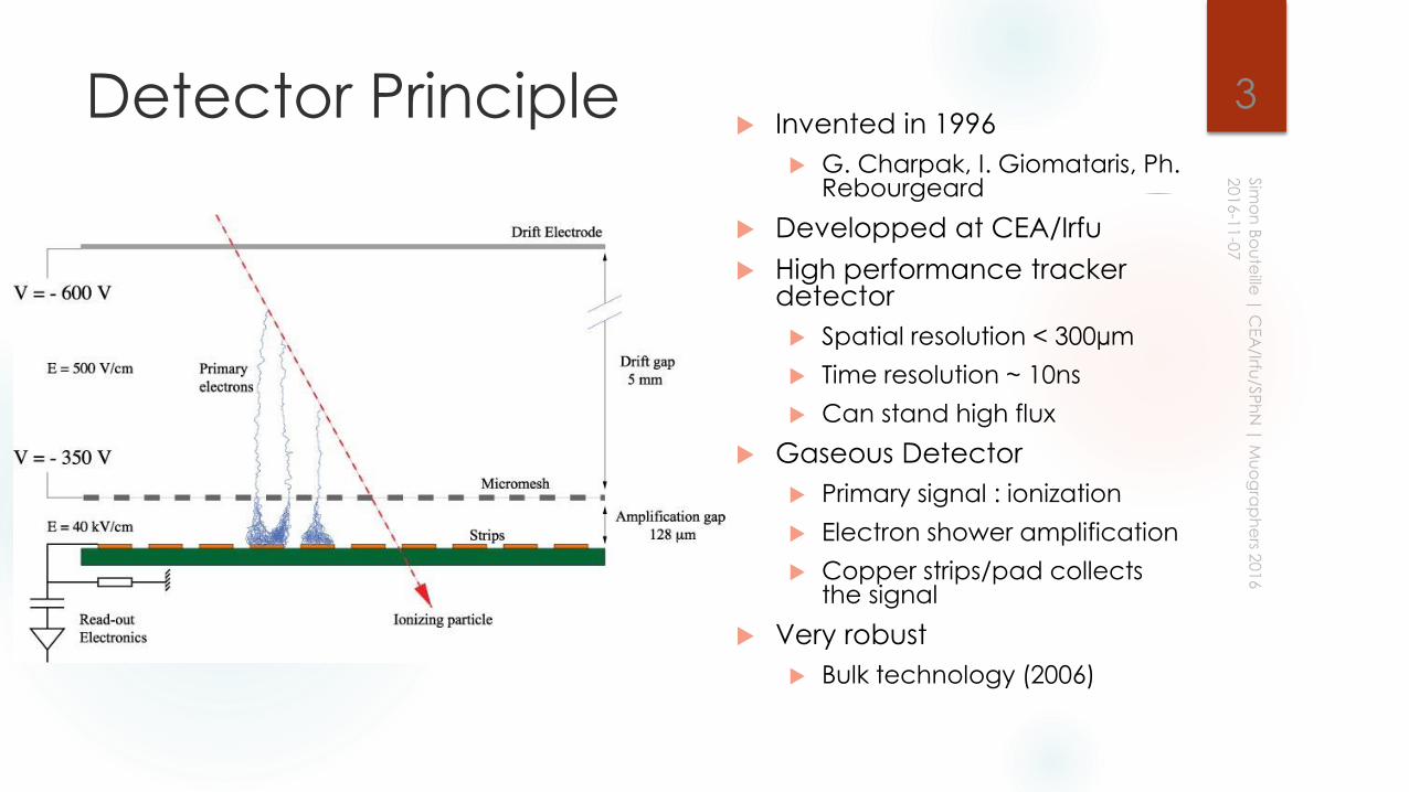
Detector Principle Invented in 1996
G. Charpak, I. Giomataris, Ph. Rebourgeard
Developped at CEA/Irfu
High performance tracker detector
Spatial resolution < 300µm
Time resolution ~ 10ns
Can stand high flux
Gaseous Detector
Primary signal : ionization
Electron shower amplification
Copper strips/pad collects the signal
Very robust
Bulk technology (2006)
3
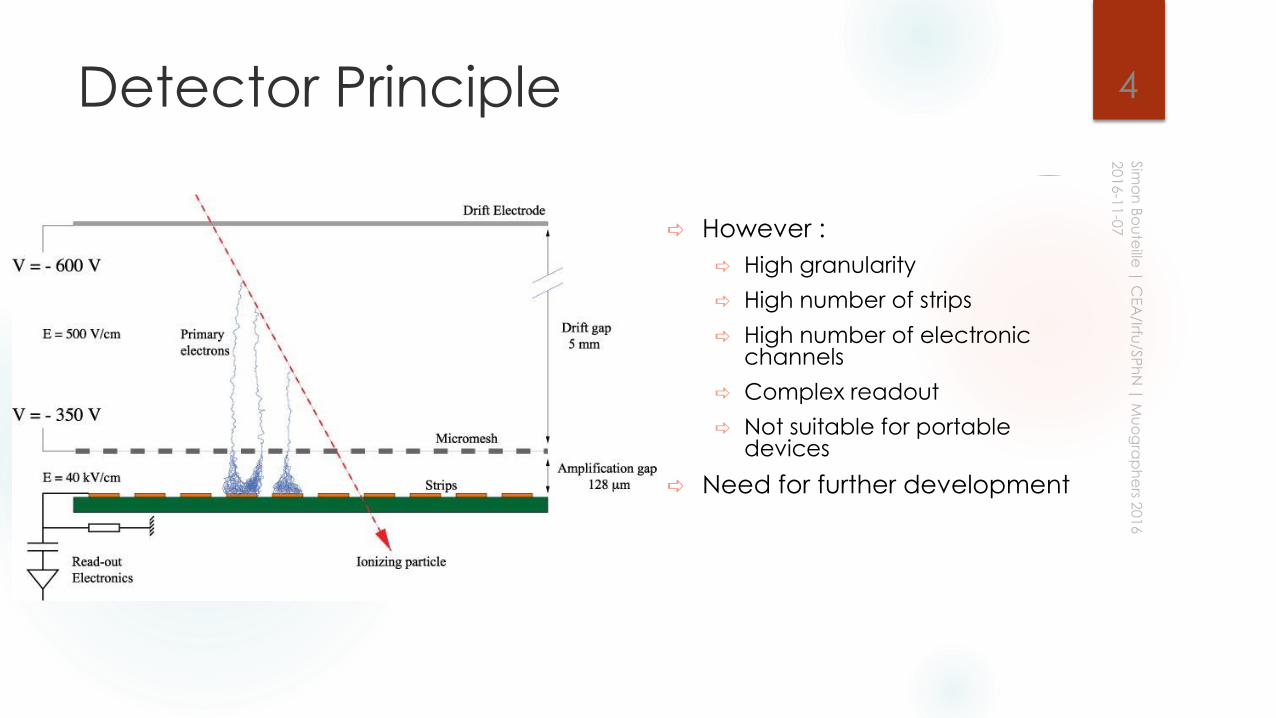
Detector Principle
However :
High granularity
High number of strips
High number of electronic channels
Complex readout
Not suitable for portable devices
Need for further development
4
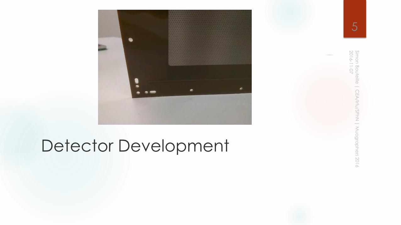
Detector Development
5
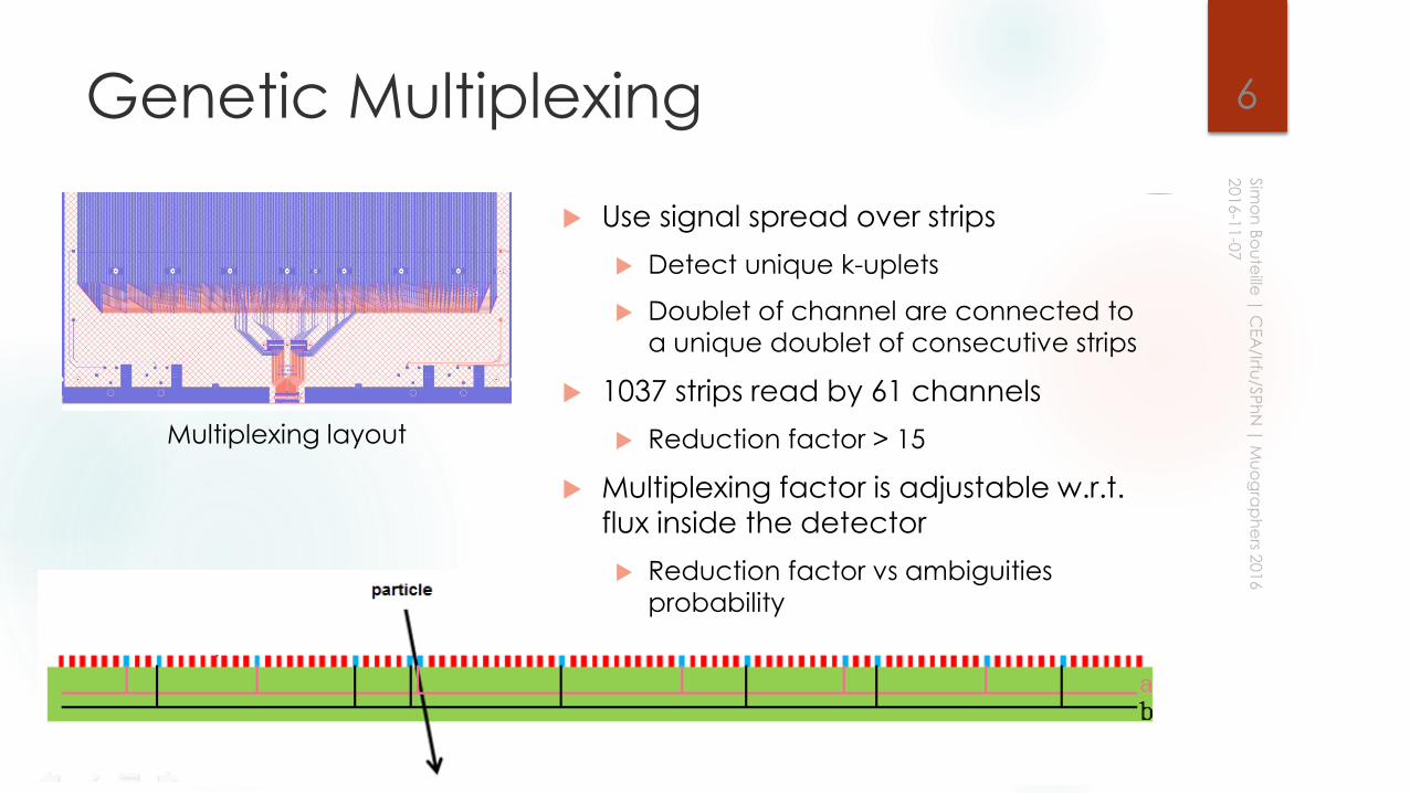
Genetic Multiplexing
Use signal spread over strips
Detect unique k-uplets
Doublet of channel are connected to
a unique doublet of consecutive strips
1037 strips read by 61 channels
Reduction factor > 15
Multiplexing factor is adjustable w.r.t.
flux inside the detector
Reduction factor vs ambiguities
probability
6
Multiplexing layout
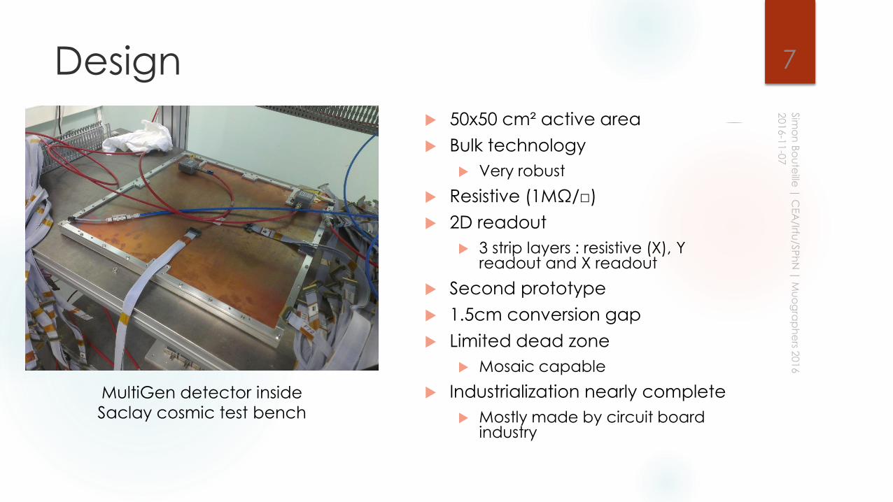
Design
50x50 cm² active area
Bulk technology
Very robust
Resistive (1MΩ/□)
2D readout
3 strip layers : resistive (X), Y readout and X readout
Second prototype
1.5cm conversion gap
Limited dead zone
Mosaic capable
Industrialization nearly complete
Mostly made by circuit board industry
7
MultiGen detector inside
Saclay cosmic test bench
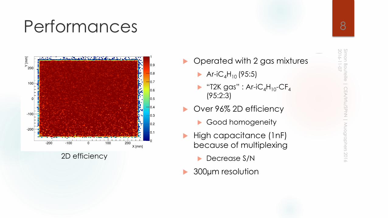
Performances
Operated with 2 gas mixtures
Ar-iC4H10 (95:5)
“T2K gas” : Ar-iC4H10-CF4
(95:2:3)
Over 96% 2D efficiency
Good homogeneity
High capacitance (1nF)
because of multiplexing
Decrease S/N
300µm resolution
8
2D efficiency
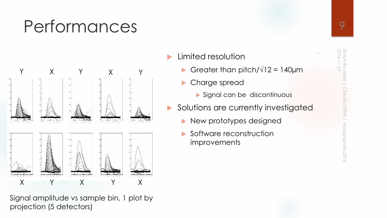
Performances
Limited resolution
Greater than pitch/√12 = 140µm
Charge spread
Signal can be discontinuous
Solutions are currently investigated
New prototypes designed
Software reconstruction
improvements
Signal amplitude vs sample bin, 1 plot by
projection (5 detectors)
XX
X X X
Y Y Y
Y Y
9

Electronics development
10
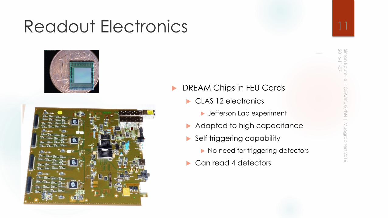
Readout Electronics
DREAM Chips in FEU Cards
CLAS 12 electronics
Jefferson Lab experiment
Adapted to high capacitance
Self triggering capability
No need for triggering detectors
Can read 4 detectors
11
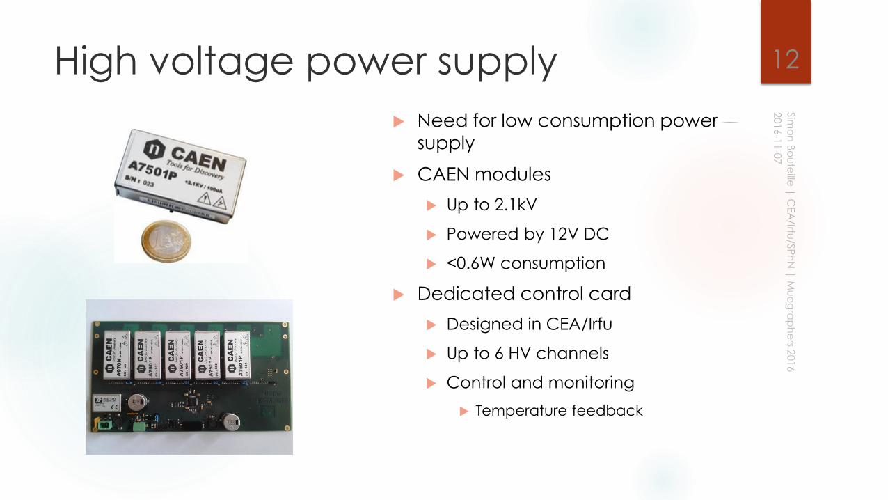
High voltage power supply
Need for low consumption power
supply
CAEN modules
Up to 2.1kV
Powered by 12V DC
<0.6W consumption
Dedicated control card
Designed in CEA/Irfu
Up to 6 HV channels
Control and monitoring
Temperature feedback
12
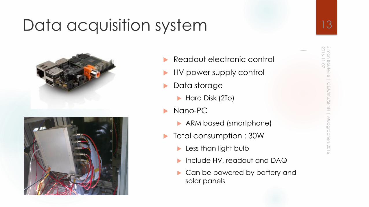
Data acquisition system
Readout electronic control
HV power supply control
Data storage
Hard Disk (2To)
Nano-PC
ARM based (smartphone)
Total consumption : 30W
Less than light bulb
Include HV, readout and DAQ
Can be powered by battery and
solar panels
13
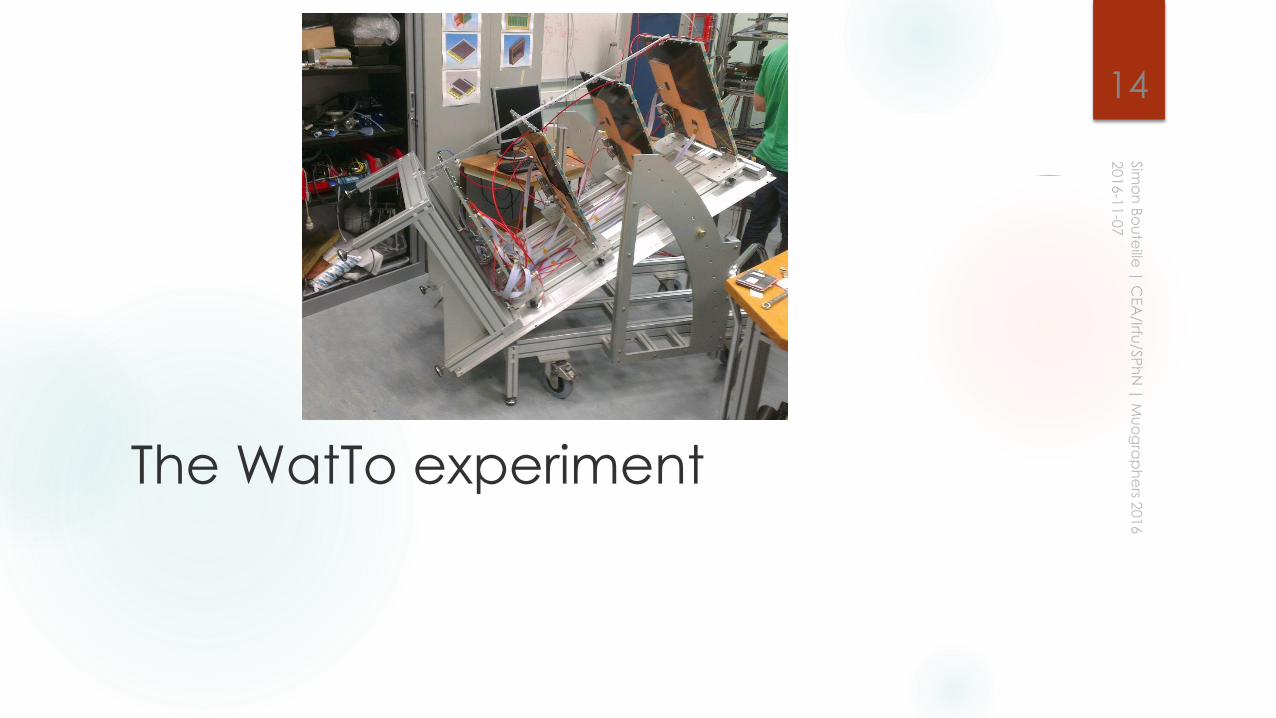
The WatTo experiment
14
Purpose
Proof that Micromegas can work outside of labs
Worldwide first operation of a Micromegas tracker outside a lab
Proof of concept validation
Test self-trigger
Test battery power operation
Check noise levels
Check outside environment influence
Make an experiment in a semi-controlled environment
Inside Saclay center
Easy operation but in real conditions
Muography of the water tower
15
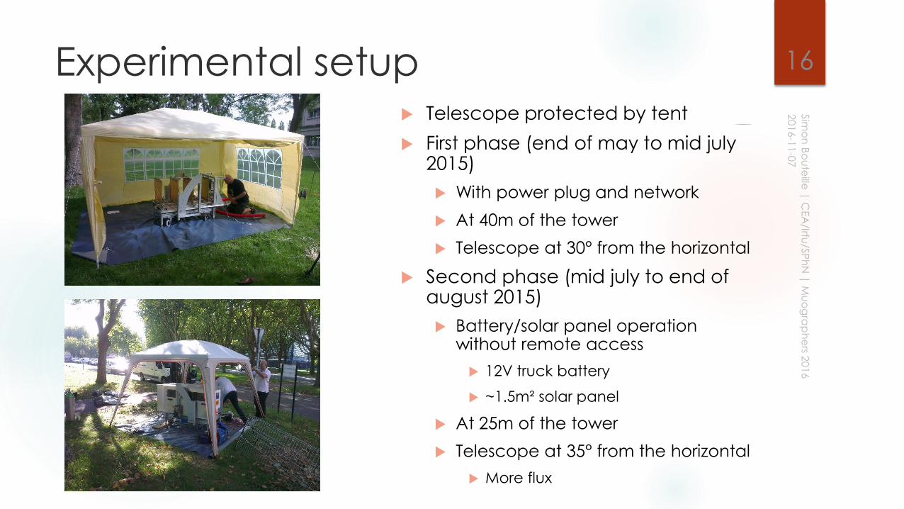
Experimental setup Telescope protected by tent
First phase (end of may to mid july2015)
With power plug and network
At 40m of the tower
Telescope at 30° from the horizontal
Second phase (mid july to end of august 2015)
Battery/solar panel operation without remote access
12V truck battery
~1.5m² solar panel
At 25m of the tower
Telescope at 35° from the horizontal
More flux
16
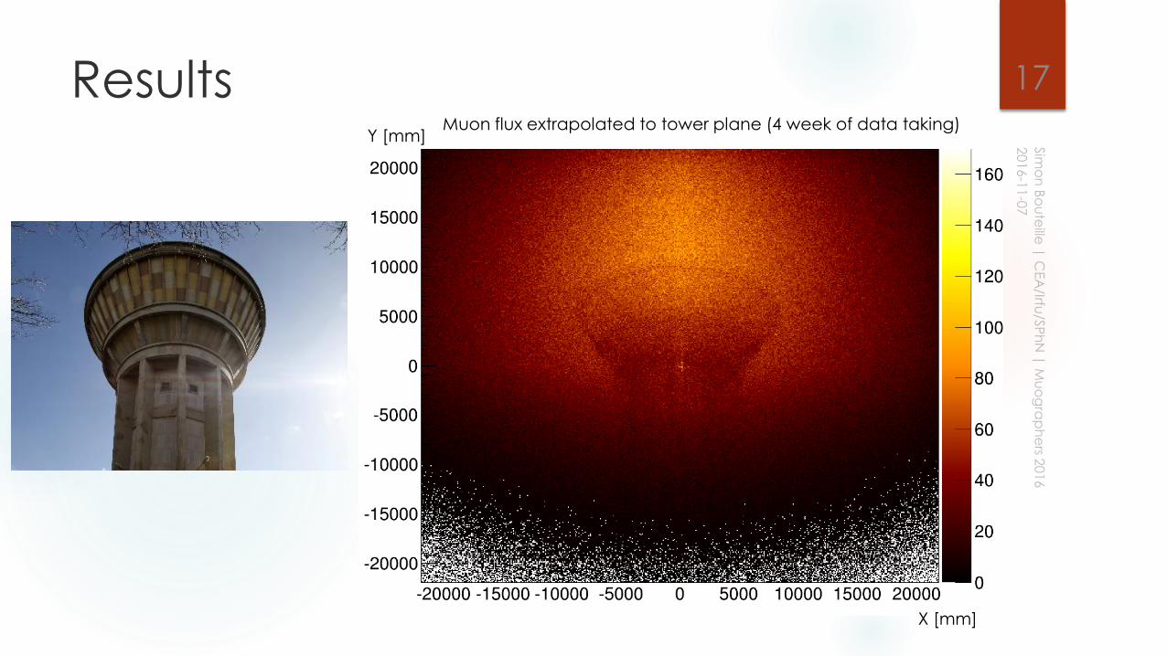
ResultsMuon flux extrapolated to tower plane (4 week of data taking)
X [mm]
Y [mm]
17
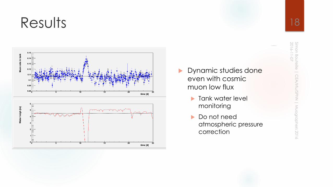
Results
Dynamic studies done
even with cosmic
muon low flux
Tank water level
monitoring
Do not need
atmospheric pressure
correction
18
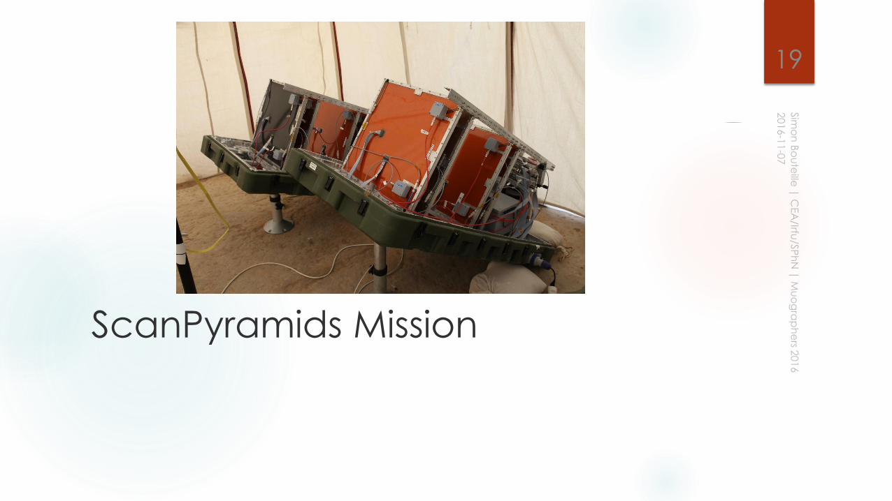
ScanPyramids Mission
19
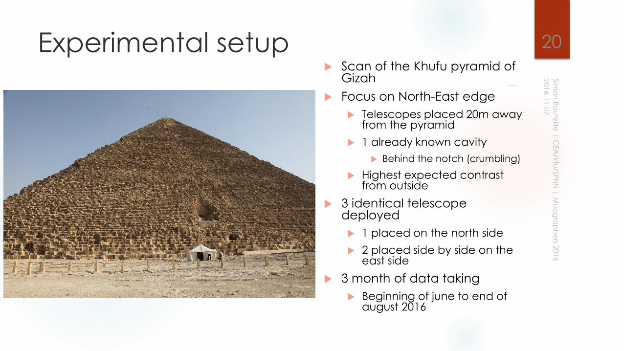
Experimental setup Scan of the Khufu pyramid of
Gizah
Focus on North-East edge
Telescopes placed 20m away from the pyramid
1 already known cavity
Behind the notch (crumbling)
Highest expected contrast from outside
3 identical telescope deployed
1 placed on the north side
2 placed side by side on the east side
3 month of data taking
Beginning of june to end of august 2016
20
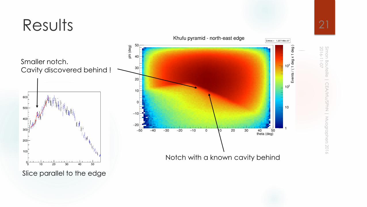
Results 21
Notch with a known cavity behind
Smaller notch.
Cavity discovered behind !
Slice parallel to the edge
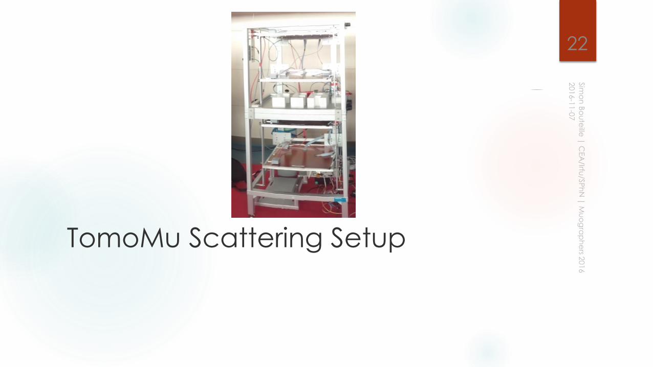
TomoMu Scattering Setup
22
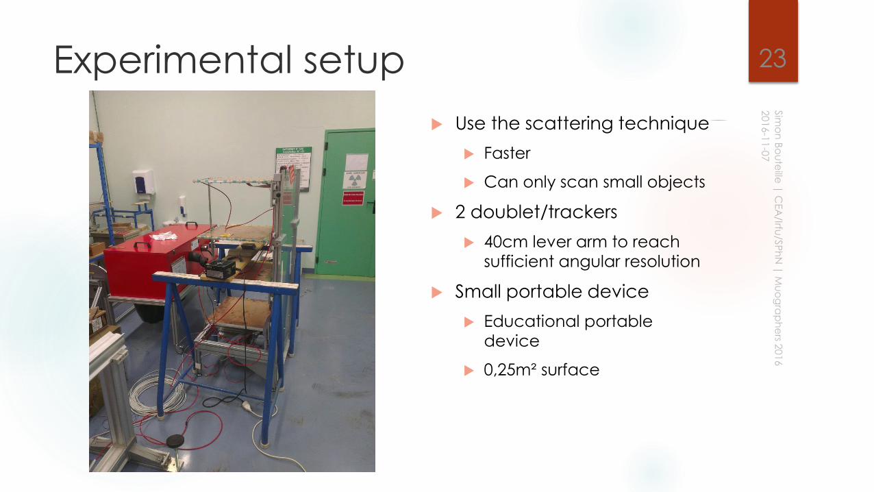
Experimental setup
Use the scattering technique
Faster
Can only scan small objects
2 doublet/trackers
40cm lever arm to reach
sufficient angular resolution
Small portable device
Educational portable
device
0,25m² surface
23
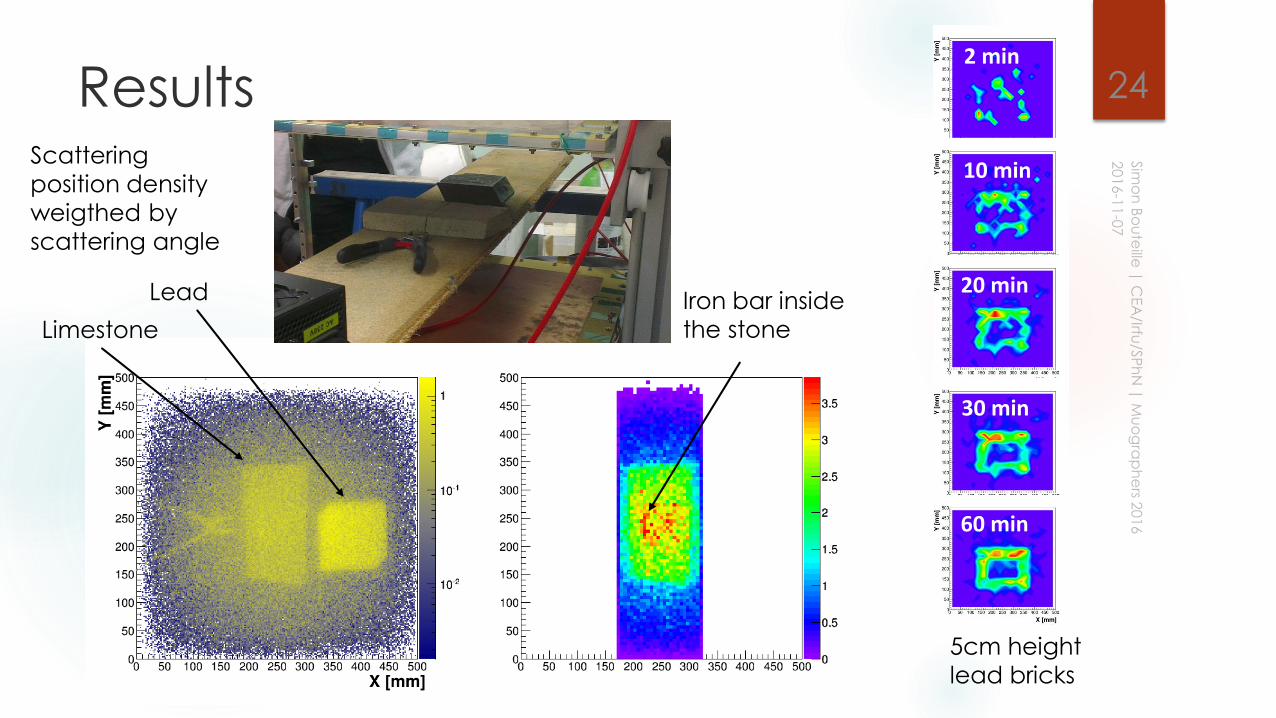
Results 24
Scattering
position density
weigthed by
scattering angle
Iron bar inside
the stone
Lead
Limestone
2 min
60 min
30 min
20 min
10 min
5cm height
lead bricks
Conclusion
We successfully operated Micromegas muography telescopes both
in Paris and Egypt
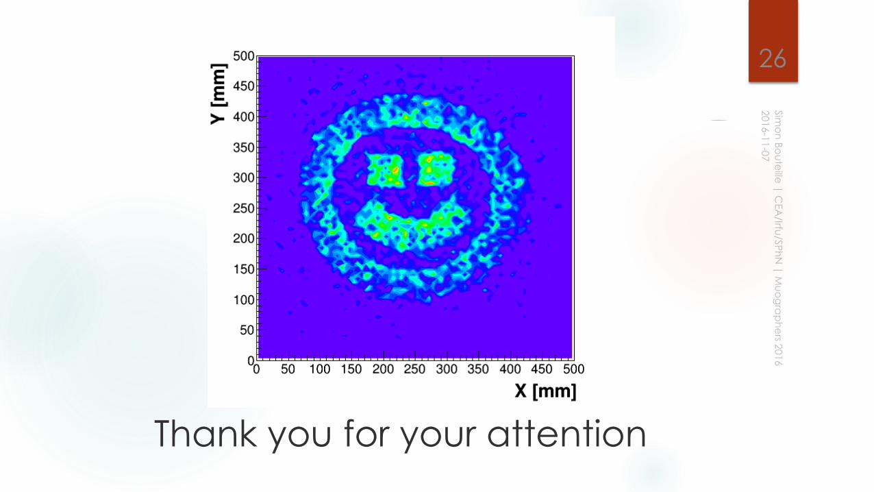
Attempt to make a full 3D view of an object using the scattering
technique is ongoing
34 50x50cm² Micromegas had been made so far for the muography
projects
2/3 of them were made by Elvia (French industry)
25
26
Thank you for your attention