Embed Size (px)
Citation preview

MX4000Genex™ Series
Simplex Multiplexer
Installation/Operation Manual
C1927M (5/99)
Pelco • 300 W. Pontiac Way, Clovis • CA 93612-5699 USA • Pelco Online @ http://www.pelco.com
In North America and Canada: Tel (800) 289-9100 or FAX (800) 289-9150 • DataFAX (800) 289-9108
International Customers: Tel (1-559) 292-1981 or FAX (1-559) 348-1120 • DataFAX (1-559) 292-0435
GENEX
PELCO
R
LISTEDUL®
2 Pelco Manual C1927M (5/99)
CONTENTS
Section Page
IMPORTANT SAFEGUARDS AND WARNINGS................................................................ 5
DESCRIPTION ................................................................................................................... 5WHAT IS A VIDEO MULTIPLEXER?.......................................................................... 5GENEX™ SERIES SIMPLEX MULTIPLEXERS ........................................................ 6APPLICATIONS ......................................................................................................... 6MODELS .................................................................................................................... 8
INSTALLATION .................................................................................................................. 9BASIC INSTALLATION .............................................................................................. 9
MOUNTING ....................................................................................................... 9CAMERAS ........................................................................................................ 10MONITORS ....................................................................................................... 11VCR .................................................................................................................. 11PELCO’S TIME-LAPSE VCRS ......................................................................... 13ALARMS ........................................................................................................... 13POWERING THE MULTIPLEXER ....................................................................14
MULTIPLEXER WITH KBD4000 KEYBOARD .......................................................... 14MULTIPLEXER WITH MX4000SVR SERVER .......................................................... 15
OPERATION .....................................................................................................................15
PROGRAMMING ..............................................................................................................19PASSWORD ............................................................................................................. 19MENUS .....................................................................................................................19
SYSTEM SETUP (VIEW BUTTON) ..................................................................19ADVANCED SYSTEM SETUP (VIEW BUTTON) .............................................21RECORD SETUP (DISPLAY/RECORD BUTTON) ...........................................23CUSTOM VCR SETUP (DISPLAY/RECORD BUTTON) ..................................25CAMERA SETUP (CAMERA BUTTONS) .........................................................26ACTIVITY MASK SETUP .................................................................................. 27SEQUENCE SETUP (SEQUENCE BUTTON) ..................................................28HELP MENU .....................................................................................................29
MULTIPLE CAMERA DISPLAY SETUP ....................................................................29PROGRAMMING THE PICTURE-IN-PICTURE DISPLAY ( BUTTON) .... 29
PROGRAMMING THE 4-CAMERA DISPLAYS ( BUTTON) .....................30
PROGRAMMING THE 9-CAMERA DISPLAYS ( BUTTON) .....................30
PROGRAMMING THE 16-CAMERA DISPLAY ( BUTTON) .....................30PROGRAMMING MENU DEFAULTS ....................................................................... 31
TROUBLESHOOTING ...................................................................................................... 32
SPECIFICATIONS............................................................................................................. 33REGULATORY NOTICES ......................................................................................... 34
WARRANTY AND RETURN INFORMATION ....................................................................34

Pelco Manual C1927M (5/99) 3
LIST OF ILLUSTRATIONS
Figure Page
1 Stand-Alone Multiplexer ..................................................................................... 72 Multiplexers with KBD4000 Keyboard ................................................................ 73 Multiplexers with KBD4000 Keyboards and MX4000SVR Server ..................... 84 Rack Installation ................................................................................................. 95 Camera Wiring Example ...................................................................................106 VCR Wiring Example ........................................................................................ 117 Pelco Time-Lapse VCR Wiring Example .......................................................... 128 Alarm Wiring Example ......................................................................................139 Front Panel, 9-Channel Color Simplex Multiplexer ...........................................1510 Front Panel, 16-Channel Color Simplex Multiplexer .........................................1511 Basic System Setup Menu ................................................................................ 2012 Advanced System Setup Menu ......................................................................... 2113 Basic VCR Settings Menu .................................................................................2414 Custom VCR Setup Menu .................................................................................2515 Basic Camera Menu ......................................................................................... 2616 Activity Dectection Mask ...................................................................................2717 Camera Sequence Menu .................................................................................. 2918 Help Menu .........................................................................................................29
LIST OF TABLES
Table Page
A Video Coaxial Cable Requirements ..................................................................10B Front Panel Controls ......................................................................................... 16C Operation Guide ................................................................................................17D VCR Types ........................................................................................................ 24E Programming Menu Defaults ............................................................................31

4 Pelco Manual C1927M (5/99)
(This page intentionally left blank.)

Pelco Manual C1927M (5/99) 5
IMPORTANT SAFEGUARDS AND WARNINGS
Prior to installation and use of this product, the following WARNINGS should be observed.
1. Installation and servicing should only be done by qualified service personnel andconform to all local codes.
2. Unless the unit is specifically marked as a NEMA Type 3, 3R, 3S, 4, 4X, 6, or 6Penclosure, it is designed for indoor use only and it must not be installed whereexposed to rain and moisture.
3. Only use replacement parts recommended by Pelco.
4. After replacement/repair of this unit’s electrical components, conduct a resistancemeasurement between line and exposed parts to verify the exposed parts have notbeen connected to line circuitry.
Please thoroughly familiarize yourself with the information in this manual prior to installationand operation.
DESCRIPTION
Thank you and congratulations on selecting Pelco’s Genex™ Series multiplexer. You havechosen to work with the highest quality, most sophisticated yet easy-to-use video multi-plexer on the market today. Using ActiveImage™ technology, the Genex™ Series multiplex-ers have exceptionally high resolution digital multiple-screen displays.
With the addition of the KBD4000 remote keyboard and/or the MX4000SVR multiplexerserver, the Genex™ Series offers the greatest degree of system flexibility and expandabilityas well.
WHAT IS A VIDEO MULTIPLEXER?
Wherever closed circuit television (CCTV) systems are used, there is often a need torecord and display many different camera views. Whether it is in a small retail environment,a large casino, or an airport, multiplexers have become the preferred method of collectingpictures from as many as 16 cameras for recording on a single time-lapse VCR.
In addition, multiplexers allow users to watch up to 16 cameras simultaneously on onescreen, either live or in playback. Should a scene require closer examination, the user canselect full-screen viewing without the loss of detail, as occurs with “quad” devices thatcompress four pictures into one for recording.
The multiplexer acts as an interface between the CCTV cameras and the time-lapse VCR.The multiplexer is designed to switch between cameras much like an ordinary sequentialswitcher. Unlike a switcher, however, a multiplexer should switch at exactly the same rateas the VCR is recording so that just one video picture, or field, is recorded from eachcamera before it switches to the next camera. The reason for this is that with a largenumber of cameras, you need to switch as fast as you possibly can in order to minimize thetime gap between successive pictures from a given camera.
In most respects, time-lapse VCRs are very similar to the VHS video recorder that youprobably have in your home. The single largest difference is that a time-lapse VCR allowsas much as 960 hours of video to be recorded on a single T-120 (two-hour) VHS cassette.The total amount of time varies by make and model, but even the lowest cost models allowfor a lot longer recording time than a normal consumer VCR.
When you record a tape on your home VCR and play the tape, you see normal motion, justas you do on your television. If you connect one camera to a multiplexer and record thevideo at the two-hour speed on a time-lapse recorder, motion will appear normal when youplay the tape, just like on your home VCR. But as you add more cameras to the multiplexer,the multiplexer has to switch between cameras and there is a gap in the video picturesrecorded for any one camera. The more cameras there are, the longer the gap is becauseit takes longer for the multiplexer to switch between all the cameras. When the tape isplayed, the motion becomes jerky because of the missing video.

6 Pelco Manual C1927M (5/99)
Not only does the number of cameras affect the time gap, but so does the recording speed.The slower the recording speed, the longer the gap. Normal recording speed for full motionis the two-hour mode. But if you slow the recording speed down to record 12 hours, 48hours, or 960 hours of video on a two-hour tape, it means that a lot of video is left out.
Thus, the more cameras there are and the slower the recording speed, the longer the timegap becomes between recorded pictures for any one camera. It is important to understandthis concept because, depending on what you are recording, important video could be lost.In a system with two or three cameras recording in 12-hour mode, a person might appearon the left side of the screen, then the left center, then the right center, and finally the rightside of the screen. But in a system with 16 cameras recording in 120-hour mode, a personmight appear on the left side of the screen and be gone in the next picture.
GENEX™ SERIES SIMPLEX MULTIPLEXERS
The MX4000 Genex™ Series is a high-quality family of simplex multiplexers that canaccept video inputs from a maximum of 9 or 16 cameras, depending on the model. Thesimplex multiplexers have three modes of operation: live, record, and VCR.
• In the live mode, the main monitor can show live video both in full-screen or multiple-screen views. You cannot record in the live mode.
• In the record mode, the main monitor will show live video of an individual camera infull-screen view only. You can record only in the record mode. While recording, allcameras are being recorded simultaneously.
• In the VCR mode, the main monitor will display full-screen or multiple-screen views ofvideotape playback. You cannot record in the VCR mode.
Video from the cameras can be shown on two monitors: main and spot.
The main monitor displays video from a single camera or from multiple cameras. Video canbe either live or from a tape playback. Multiple-screen displays can be picture-in-picture, 4-,9-, or 16-camera formats.
A spot monitor displays live video from a single camera. A spot monitor is optional, butincreases the flexibility of your system. For example, you can keep an eye on all camerasin a multiple-screen format on the main monitor while watching a full-screen view of anyone camera on the spot monitor. Or, if you are playing a tape on the main monitor, you canuse the spot monitor to watch live video.
Cameras can be sequenced on both monitors.
In the full-screen view on the main monitor, a zoom function doubles or quadruples theimage size for better viewing.
Depending on the model, there are 9 or 16 alarm inputs–one per camera–that tag thecamera images when an alarm is activated. The main and spot monitors can be pro-grammed to display alarms. Alarm inputs also activate a relay output, which can be used tochange a VCR to its preprogrammed alarm record speed. When there is an alarm, theVCR, depending on how it is programmed, will either record alarm cameras only or recordboth alarm and non-alarm cameras. An alarm log lists the last 20 alarms.
Activity detection continually monitors selected camera inputs for motion. When themultiplexer detects motion, it increases the frequency at which it records a camera orcameras with motion. The main and spot monitors can be programmed to display motion-detection activated switching.
APPLICATIONS
The MX4000 Genex™ Series is very flexible in its design, allowing you to configure yoursystem in a variety of ways.
The simplest system is a stand-alone multiplexer (refer to Figure 1). All you have to do isconnect cameras, monitors, a VCR, and alarm inputs. Operation of the multiplexer is donewith front panel push buttons.

Pelco Manual C1927M (5/99) 7
Figure 2. Multiplexers with KBD4000 Keyboard
By adding a KBD4000 keyboard to the multiplexer (refer to Figure 2), you can control 1-16multiplexers from up to 25 feet (7.6 m) away with the cable supplied with the keyboard.Greater distances between the multiplexer and keyboard can be obtained if you provide aPelco KBDKIT(-X) and your own cable.
A keyboard also gives you the added capability of controlling moveable cameras. Controlsystems for moveable cameras must be Coaxitron® compatible. In Figure 1 cameras arefixed.
The systems shown in Figures 1 and 2 are for a single operator only. To permit up to fouroperators to use the system, an MX4000SVR multiplexer server can be added, as shown inFigure 3.
The main and spot monitor outputs from each multiplexer are connected to the server,providing two video channels. The design is not a true matrix, however, because only twooperators (instead of all operators in a true matrix ) can select cameras from the samemultiplexer at the same time, one operator using the main monitor and the other operatorusing the spot monitor.
Figure 1. Stand-Alone Multiplexer
CAMERAS –16 MAXIMUM
VCR
MAINMONITOR
SPOTMONITOR(OPTIONAL)
MX4000 MULTIPLEXER
DISPLAYRECORD
Sim
CAMERAS –16 MAXIMUM
VCR
MAINMONITOR
SPOTMONITOR(OPTIONAL)
F2
F3
PRESETMACRO
78
0
CAM
KBD4000
TOADDITIONALMULTIPLEXERS
DISPLAYRECORD
Sim
MX4000 MULTIPLEXER - 16 MAXIMUM
NOTE: The KBD4000 key-board in combination with amultiplexer providesCoaxitron® control of pan,tilt, and lens functions.
When used with 15-bit stan-dard Coaxitron® receivers,such as the CX9000 Series,the PT7700, and the ED25/27/28/29, the KBD4000 key-board in conjunction with amultiplexer supports all pan,tilt, and lens functions, andAUX on/off. The keyboardwill not set or call presets orsupport preset scanning.
When used with 32-bit ex-tended Coaxitron® receivers,such as Intercept®, Spec-tra®, and LRD41C21/LRD41C22 Series, theKBD4000 keyboard in con-junction with a multiplexerwill support all the functionsof a 15-bit receiver, includ-ing the setting and calling ofpresets and patterns. It willnot support programming oflabels for presets or pat-terns. If labels for presets orpatterns are required, theywould need to be pro-grammed with a differentcontrol, such as theMPT9500.

8 Pelco Manual C1927M (5/99)
MODELS
Color Simplex
MX4009CS 9-channel, color simplex multiplexer, NTSC standard, 120 VAC, 60 Hz(UL, cUL, FCC)
MX4009CS-X Same as MX4009CS except PAL standard, 230 VAC, 50 Hz (CE)MX4016CS 16-channel, color simplex multiplexer, NTSC standard, 120 VAC, 60
Hz (UL, cUL, FCC)MX4016CS-X Same as MX4016CS except PAL standard, 230 VAC, 50 Hz (CE)
Monochrome Simplex
MX4009MS 9-channel, monochrome simplex multiplexer, EIA RS-170 standard,120 VAC, 60 Hz (UL, cUL, FCC)
MX4009MS-X Same as MX4009MS except CCIR standard, 230 VAC, 50 Hz (CE)MX4016MS 16-channel, monochrome simplex multiplexer, EIA RS-170 standard,
120 VAC, 60 Hz (UL, cUL, FCC)MX4016MS-X Same as MX4016MS except CCIR standard, 230 VAC, 50 Hz (CE)
Figure 3. Multiplexers with KBD4000 Keyboards and MX4000SVR Server
LOCAL PORTREMOTEPORT
KBDKIT(-X)
DISPLAYRECORD
DISPLAYRECORD
DISPLAYRECORD
MX4000SVRMultiplexer Server
Made In USA
MX4000SVRMULTIPLEXERSERVER
F2
F3
PRESETMACRO
78
0
CAM
F2
F3
PRESETMACRO
78
0
CAM
F2
F3
PRESETMACRO
78
0
CAM
F2
F3
PRESETMACRO
78
0
CAM
KBD4000KEYBOARD(4 MAXIMUM) MONITOR (4 MAXIMUM)
TO OTHERMULTIPLEXERS
MAIN MONITOROUTPUT FROMMULTIPLEXER
SPOT MONITOROUTPUT FROMMULTIPLEXER(OPTIONAL)
MX4000 MULTIPLEXER (8 MAXIMUM)
Multiplexer ServerGENEX™

Pelco Manual C1927M (5/99) 9
INSTALLATION
Unpack and inspect all parts carefully.
The following parts are supplied:
1 MX4000 Series multiplexer1 Rack ear kit
2 Rack ears4 4-40 x .375-inch pan head screws4 10-32 x .750-inch pan head screws
1 Power cord1 6-foot (1.8 m) data cable with RJ-45 connectors
Installation of the multiplexer varies according to the type of installation.
The Basic Installation section covers the basic installation procedures for all applications.
This section also covers the complete installation instructions of a stand-alone multiplexer(refer to Figure 1 in the Applications section).
The Multiplexer with KBD4000 Keyboard section, provides additional procedures beyondthe basic instructions for installing up to 16 multiplexers that are controlled by a singleKBD4000 keyboard (refer to Figure 2).
The Multiplexer with MX4000SVR Server section, gives additional steps beyond the basicinstructions for installing up to eight multiplexers that are controlled from as many as fourKBD4000 keyboards. The multiplexers and keyboards are linked together through a server(refer to Figure 3). A KBDKIT(-X) is required for each keyboard connected to the remote port.
Rear panel views shown in the installation procedures are for 16-channel color models. The9-channel models have fewer video inputs and outputs. Monochrome models have noSVHS connections.
BASIC INSTALLATION
MOUNTINGThe multiplexer can be placed on a flat surface, such as a desk or shelf, or it can beinstalled in a 19-inch (48.26 cm) equipment rack.
To install the multiplexer in an equipment rack (refer to Figure 4):
1. Remove the four rubber feet (A) from the bottom of the unit.
2. Remove the front two flat-head screws (B) on each side of the multiplexer. Discard thescrews.
Figure 4. Rack InstallationA
C
B
D

10 Pelco Manual C1927M (5/99)
3. Attach the rack ears (C) to the multiplexer. The rack ears are universal and can beused on either side of the unit. Attach the ears with the 4-40 x .375-inch screws (D)that are supplied with the ears. Only the two bottom holes on the rack ears are neededfor mounting.
4. Install the multiplexer in the rack using the four 10-32 x .750-inch screws that aresupplied.
Proceed to the Cameras section.
CAMERASVideo inputs can come from any conventional source. No external camera synchronizationis required. Refer to Table A for the type of video coaxial cable to use.
To connect cameras (refer to Figure 5):
1. Connect the coaxial cables from your cameras or receivers to the IN connectors. Ifyou are using moveable cameras, the receivers must be Coaxitron® compatible.
Stand-Alone Multiplexer - Connect fixed cameras. Moveable cameras may beused if the video is looped out to an MPT9500 Series controller.
Multiplexer with KBD4000 - Connect fixed or moveable cameras.
Multiplexer with KBD4000 and MX4000SVR Server - Connect fixed ormoveable cameras.
2. If you want to loop a video signal out to another device, connect coaxial cables fromthe looping OUT connectors to the external equipment.
3. Termination of the camera inputs is programmable and is described in the Program-ming section.
Proceed to the Monitors section.
Table A. Video Coaxial Cable Requirements
Cable Type* Maximum Distance
RG59/U 750 ft (229 m)RG6/U 1,000 ft (305 m)RG11/U 1,500 ft (457 m)
* Minimum cable requirements:75 ohmsAll-copper center conductorAll-copper braided shield with 95% braid coverage
Figure 5. Camera Wiring Example
16
VCRMAINSPOT
OUT IN
SVHS
IN COM OUT
ALARMS
1 2 3 4 5 6 7 8 9 10 11 14 1512 13 110-240V~50/60Hz
N NHOCC S
LOOPED VIDEO OUTPUT
NOTE: Camera powershould be wired in phase toall cameras. When camerasare sequenced, they will rollon the spot monitor if theyare out of phase. On themain monitor, cameras aredigitally time corrected andwill not roll when sequencedif they are out of phase.
Pelco Manual C1927M (5/99) 11
MONITORSMain Monitor - The main monitor can show live video of an individual camera or asequence of individual cameras, the same as the spot monitor. But the main monitor is theonly monitor that can show multi-screen displays (more than one camera displayedsimultaneously), run multi-screen sequences, play back video from a VCR, or use thedigital zoom feature of the multiplexer. These functions can be done only when the multi-plexer is in DISPLAY mode. The multiplexer will not record in DISPLAY mode.
The monitor can be overridden by an alarm(s) and/or activity detection.
Cameras are digitally time corrected in LIVE and VCR modes and will not roll whensequenced if they are out of phase.
Connect your main monitor to the MAIN output. Refer to Table A for the type of videocoaxial cable to use.
Spot Monitor (Optional) - The operator can manually call up live video of an individualcamera or a sequence of individual cameras.
The monitor can be overridden by an alarm(s) and/or activity detection.
Cameras are not digitally time corrected and will roll when sequenced if they are out of phase.
Connect your spot monitor to the SPOT output. Refer to Table A for the type of videocoaxial cable to use.
Proceed to the VCR section.
VCRIf you have a Pelco VCR, proceed to the next section, Pelco’s Time-Lapse VCRs.
You can connect one VCR to the multiplexer to record or play tapes.
To connect a VCR:
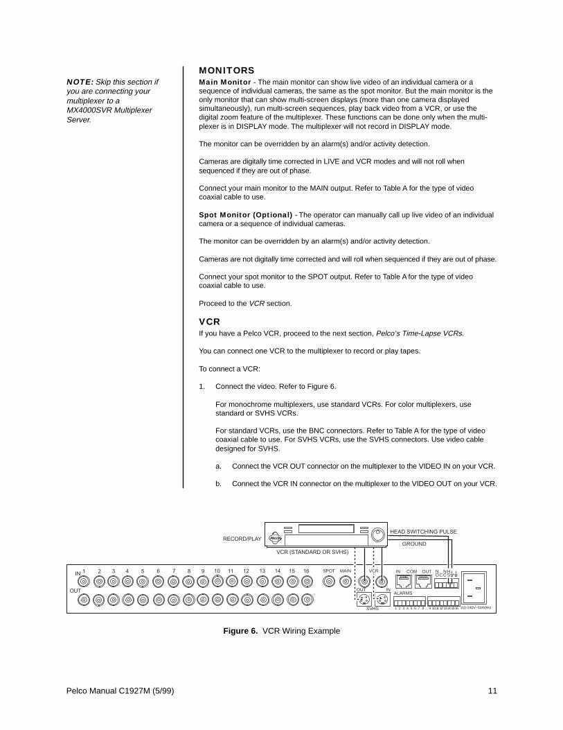
1. Connect the video. Refer to Figure 6.
For monochrome multiplexers, use standard VCRs. For color multiplexers, usestandard or SVHS VCRs.
For standard VCRs, use the BNC connectors. Refer to Table A for the type of videocoaxial cable to use. For SVHS VCRs, use the SVHS connectors. Use video cabledesigned for SVHS.
a. Connect the VCR OUT connector on the multiplexer to the VIDEO IN on your VCR.
b. Connect the VCR IN connector on the multiplexer to the VIDEO OUT on your VCR.
NOTE: Skip this section ifyou are connecting yourmultiplexer to aMX4000SVR MultiplexerServer.
Figure 6. VCR Wiring Example
RECORD/PLAYGROUND
VCRMAINSPOT
OUT IN
SVHS
IN COM OUT
ALARMS
1 2 3 4 5 6 7 8 9 10 11 14 151612 13 110-240V~50/60Hz
N NHOCC S
12 Pelco Manual C1927M (5/99)
2. For proper recording, the switching rate of the multiplexer between cameras mustmatch that of the VCR. There are two ways to do this:
a. One way is with a head switching pulse from the VCR. This is the most reliableway to synchronize the multiplexer and VCR. The pulse from the VCR tells themultiplexer how fast to switch between cameras. To use this method, connect thehead switching pulse output from the VCR to the HS (head switching) connectionon the multiplexer. Refer to Figure 6. The six-pin plug-in terminal block may bepulled out of the connector on the back of the multiplexer to facilitate ease ofwiring.
b. If a head switching pulse from the VCR is not available, you can synchronize theVCR and multiplexer by programming the multiplexer switching rate to match therecording speed of the VCR. This will be done in the Programming section, afteryou have finished installing your multiplexer. No wiring is required if you use thismethod.
Proceed to the Alarms section.
PELCO TIME-LAPSE VCR
A
B
REMOTE
RESET
IN
GND CLK
AUDIOVIDEO
IN OUT
CALL
OUT
OUTMIC
ALM
IN
RECSET RST MODE
VCRMAINSPOT
OUT IN
SVHS
IN COM OUT
ALARMS
1 2 3 4 5 6 7 8 9 10 11 14 151612 13 110-240V~50/60Hz
N NHOCC S
REMOTE
RESET
IN
GND CLK
AUDIOVIDEO
IN OUT
CALL
OUT
OUTMIC
ALM
IN
RECSET RST MODE
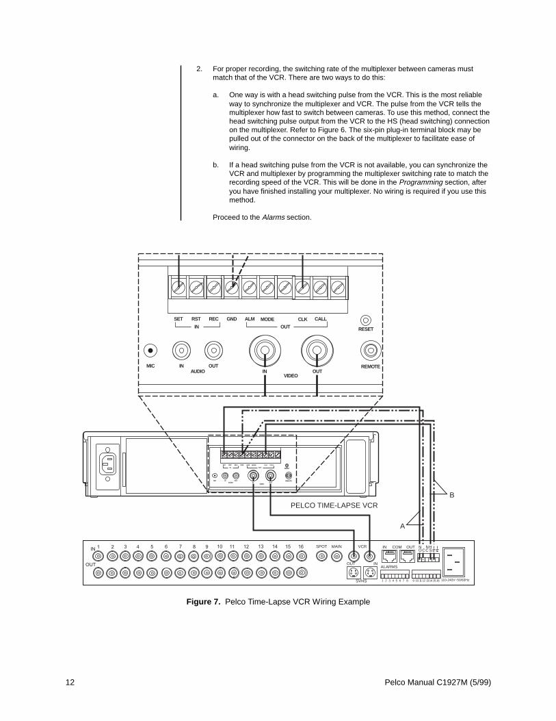
Figure 7. Pelco Time-Lapse VCR Wiring Example

Pelco Manual C1927M (5/99) 13
PELCO’S TIME-LAPSE VCRSYou can connect one of Pelco’s Time-Lapse VCR Models TLR2024, TLR2096, or TLR2168to the multiplexer as follows (refer to Figure 7):
1. Connect BNC video cable between the VCR connectors on the multiplexer and theVIDEO connectors on the VCR.
2. Automatic Speed Tracking lets the VCR control the multiplexer’s recording speed. It isthe most efficient recording method. To wire (refer to the “B” lines in Figure 7):
a. Connect the VCR’s CLK output to the multiplexer’s head switching (HS) input tosynchronize camera switching.
b. Connect the multiplexer’s ground terminal to the VCR’s GND terminal.
3. Alarm recording starts and stops recording when there are alarms. To wire (refer to the“A” lines in Figure 7):
a. Connect the multiplexer’s normally open (NO) relay terminal to the VCR’s SET IN(alarm input) terminal.
b. Connect the multiplexer’s common (C) terminal to the VCR’s GND terminal.
Proceed to the Alarms section.
ALARMSAlarm inputs require a ground signal through a contact opening or closure, such as a switchor relay.
To wire the alarm inputs (refer to Figure 8):
1. Connect one wire from the alarm source (for example, door) to one of the alarm inputpins of the multiplexer. The alarm input must correspond to the camera input. There isonly one alarm input per camera.
The eight-pin plug-in terminal blocks may be pulled out of the connectors on the backof the multiplexer to facilitate ease of wiring.
2. Connect a second wire from the alarm source to one of the ground connections on thesix-pin plug-in terminal block on the back of the multiplexer.
Figure 8. Alarm Wiring Example
GROUND
16
GROUND
VCRMAINSPOT
OUT IN
SVHS
IN COM OUT
ALARMS
1 2 3 4 5 6 7 8 9 10 11 14 1512 13 110-240V~50/60Hz
N NHOCC S

14 Pelco Manual C1927M (5/99)
3. Alarm inputs will be programmed in the Programming section for normally open ornormally closed operation.
Normally closed operation = current flow = alarm switch or relay closedNormally open operation = no current flow = alarm switch or relay open
In the example in Figure 8, current flows through the contacts (switch) in the doorwhen it is closed. When the door is open, no current flows. To cause an alarm whenthe door is opened, program the alarm input for normally closed (door is normallyclosed). To cause an alarm when the door is closed, program the alarm input fornormally open (door is normally open).
4. If your VCR has an alarm input to change the VCR to its alarm recording speed whenthe multiplexer receives an alarm, connect the VCR alarm input to the normally open(NO) relay contact on the multiplexer. Connect a wire from the relay’s common (C)connection to ground on the VCR.
Proceed to the Powering the Multiplexer section.
POWERING THE MULTIPLEXERIt is recommended that multiplexers being powered up for the first time or after extendedstorage be initialized using the following procedure. This will clear any random dataremaining in the multiplexer and initialize the memory for user programming.
1. Turn on power to your cameras, monitors, and any other equipment that is connectedto the multiplexer.
2. Plug in one end of the power cord into the multiplexer.
3. Press and hold the VIEW button on the front panel of the multiplexer while you plugthe power cord into an electrical outlet. When the Initialization Menu appears, releasethe VIEW button. The monitor will indicate PLEASE WAIT and begin a 20-secondcountdown. When the countdown has been completed, the Initialization Menu willdisappear, all programming menus will be at their default settings, and the multiplexerwill be ready for use.
If you are installing your system with a KBD4000 keyboard or MX4000SVR MultiplexerServer, proceed to the appropriate section for further installation instructions.
MULTIPLEXER WITH KBD4000 KEYBOARD
Refer to Figure 2 in the Applications section for an overview of a typical installation.
1. Follow the instructions in the Basic Installation section to mount the multiplexer; toconnect cameras, monitors, VCR, and alarms; and to power-up the multiplexer.
2. A maximum of 16 multiplexers can be daisy-chained together. If you are going todaisy-chain multiplexers, use the 6-foot (1.8 m) data cables that are supplied with themultiplexers. Connect a cable from the COM OUT port of the first multiplexer to theCOM IN port of the second multiplexer, then connect the COM OUT port of the secondmultiplexer to the COM IN port of the third multiplexer, etc.
3. Proceed to the KBD4000 Genex™ Multiplexer Keyboard Installation/Operation Manualto complete the installation, which involves setup and connection of the KBD4000keyboard, and programming the multiplexer.

Pelco Manual C1927M (5/99) 15
Figure 9. Front Panel, 9-Channel Color Simplex Multiplexer
DISPLAYRECORD
Sim
DISPLAYRECORD
Sim
Figure 10. Front Panel, 16-Channel Color Simplex Multiplexer
MULTIPLEXER WITH MX4000SVR SERVER
Refer to Figure 3 in the Applications section for an overview of a typical installation.
1. Follow the instructions in the Basic Installation section to mount the multiplexer; toconnect cameras, VCR, and alarms; and to power-up the multiplexer. Skip theMonitors section.
2. Proceed to the MX4000SVR Genex™ Multiplexer Server Installation/OperationManual to complete the installation. Also use the server manual to program the server.
3. Refer to this manual to program the multiplexer.
OPERATION
Refer to Figures 9 and 10 for views of the front panels. Monochrome front panels are thesame except for the word “Monochrome” instead of “Color” in the lower left corner.
There are three modes of operation that are selected by pressing the DISPLAY/RECORDbutton: RECORD, LIVE, VCR. The LED illuminates in the RECORD mode only. When theLED is off, look at the upper left corner of the monitor to see if the multiplexer is in the LIVEor VCR mode. The default mode is RECORD.

16 Pelco Manual C1927M (5/99)
Table B. Front Panel Controls
Button Operation Function
DISPLAY/ Press once Toggles main monitor display between record, live inputs, and playback from VCR.
RECORD In the RECORD mode, the red LED lights.
Press for 3 seconds Displays or exits the record setup menu on the main monitor.
CAMERA Press once Switches the selected camera to the main monitor (record, live, or playback).
Press twice Switches the selected camera to the spot monitor (live only).
Press for 3 seconds Displays or exits the camera setup menu on the main monitor.
SEQUENCE Press once Initiates or stops sequence on the main monitor.
Press twice Initiates or stops sequence on the spot monitor.
Press for 3 seconds Displays or exits sequence setup menu on the main monitor.
VIEW Press once In RECORD mode shows the multiplexed output to the VCR. Press again to exit.
In VCR mode shows the multiplexed input from the VCR. Press again to exit.
Press twice Displays alarm log on the main monitor.
Press twice Clears the alarm list and closes the log.
Press once Exits the alarm log without clearing the alarm list.
Press for 3 seconds Displays or exits system setup menu on the main monitor.
Press once Enables 2X zoom on displayed camera.
Press the button a second time for 4X zoom.
Press the button a third time to exit.
Press once Displays on the main monitor a picture-in-picture insert on top of full-screen
display.
Press button again to exit.
Once in the PIP mode, press for three seconds to enter the programming mode.
Press once Displays a group of four cameras on the main monitor.
Repeat pressing the button to display other groups.
Press for 3 seconds Enables programming mode to select four groups of four cameras to
display on the main monitor.
Press once Displays a group of nine cameras on the main monitor.
Press button again to display second group (16-channel models only).
Press for 3 seconds Enables programming mode to select two groups of nine cameras to
display on the main monitor.
(16-channel Press once Displays all 16 cameras on the main monitor.
models only) Press for 3 seconds Enables programming mode to select the order of 16 cameras to display on
the main monitor.
(Does not workin RECORD orVCR modes)
(Does not workin RECORDmode)
(Does not workin RECORDmode)
(Does not workin RECORDmode)
(Does not workin RECORDmode)
Pelco Manual C1927M (5/99) 17
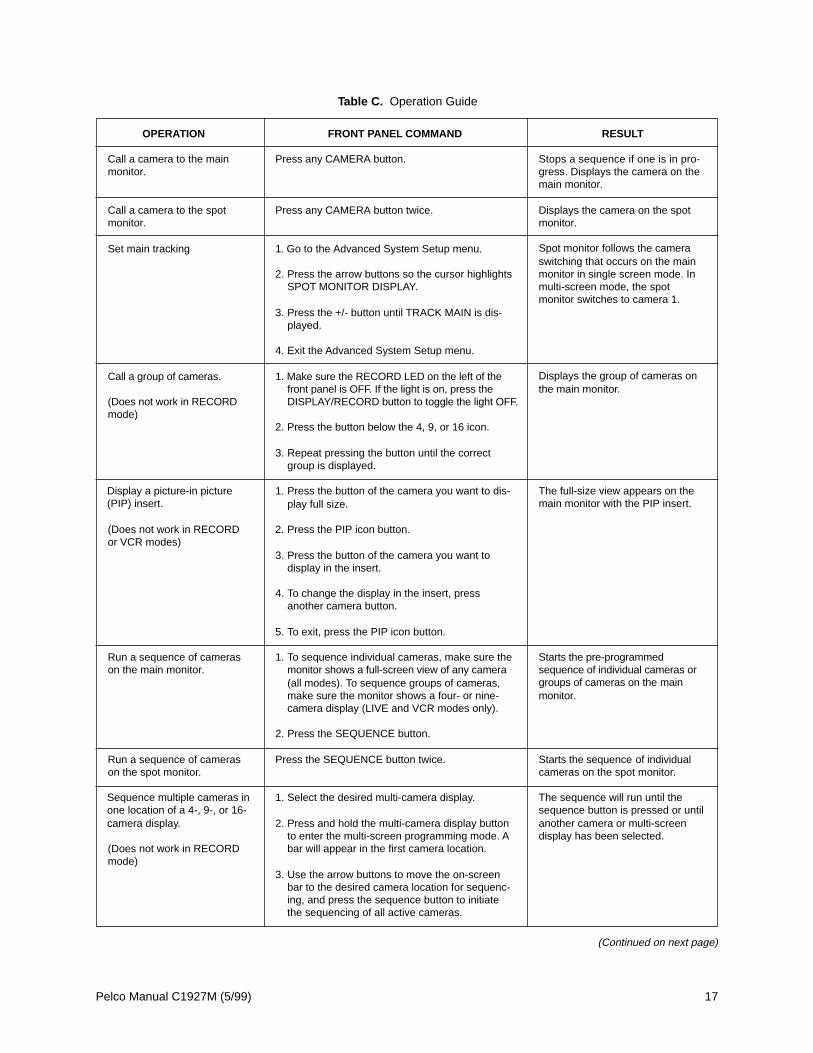
OPERATION FRONT PANEL COMMAND
Call a camera to the main Press any CAMERA button.monitor.
Call a camera to the spot Press any CAMERA button twice.monitor.
Set main tracking 1. Go to the Advanced System Setup menu.
2. Press the arrow buttons so the cursor highlightsSPOT MONITOR DISPLAY.
3. Press the +/- button until TRACK MAIN is dis-played.
4. Exit the Advanced System Setup menu.
Call a group of cameras. 1. Make sure the RECORD LED on the left of thefront panel is OFF. If the light is on, press the
(Does not work in RECORD DISPLAY/RECORD button to toggle the light OFF.mode)
2. Press the button below the 4, 9, or 16 icon.
3. Repeat pressing the button until the correctgroup is displayed.
1. Press the button of the camera you want to dis-play full size.
(Does not work in RECORD 2. Press the PIP icon button.or VCR modes)
3. Press the button of the camera you want todisplay in the insert.
4. To change the display in the insert, pressanother camera button.
5. To exit, press the PIP icon button.
1. To sequence individual cameras, make sure themonitor shows a full-screen view of any camera(all modes). To sequence groups of cameras,make sure the monitor shows a four- or nine-camera display (LIVE and VCR modes only).
2. Press the SEQUENCE button.
Press the SEQUENCE button twice.
1. Select the desired multi-camera display.
2. Press and hold the multi-camera display buttonto enter the multi-screen programming mode. A
(Does not work in RECORD bar will appear in the first camera location.mode)
3. Use the arrow buttons to move the on-screenbar to the desired camera location for sequenc-ing, and press the sequence button to initiatethe sequencing of all active cameras.
Table C. Operation Guide
RESULT
Stops a sequence if one is in pro-gress. Displays the camera on themain monitor.
Displays the camera on the spotmonitor.
Spot monitor follows the cameraswitching that occurs on the mainmonitor in single screen mode. Inmulti-screen mode, the spotmonitor switches to camera 1.
Displays the group of cameras onthe main monitor.
The full-size view appears on themain monitor with the PIP insert.
Starts the pre-programmedsequence of individual cameras orgroups of cameras on the mainmonitor.
Starts the sequence of individualcameras on the spot monitor.
The sequence will run until thesequence button is pressed or untilanother camera or multi-screendisplay has been selected.
Run a sequence of camerason the main monitor.
Display a picture-in picture(PIP) insert.
Run a sequence of camerason the spot monitor.
(Continued on next page)
Sequence multiple cameras inone location of a 4-, 9-, or 16-camera display.

18 Pelco Manual C1927M (5/99)
OPERATION FRONT PANEL COMMAND
Sequence PIP display. 1. Push the button.
(Does not work in RECORD 2. Push the SEQUENCE button.or VCR modes)
Stop a sequence. Press the SEQUENCE button once or press anyCAMERA button to stop a sequence on the mainmonitor. Press the SEQUENCE button twice tostop a sequence on the spot monitor.
Zoom on a camera. 1. Press the CAMERA button for the camera onwhich you want to zoom.
(Does not work in RECORDmode) 2. Press the button below the ZOOM icon. The
display will zoom to 2X magnification.
3. Use the arrow buttons to control the zoom loca-tion.
4. Press the zoom button a second time toincrease the zoom to 4X.
5. To exit, press the zoom button a third time.
Record a tape. Recording is done automatically as long as a VCRis connected and both the multiplexer and VCRare in the RECORD mode. While the multiplexeris in the RECORD mode (RECORD LED is on),you can only see a full-screen view of one camera(or one camera at a time if sequencing) on themain monitor.
Play a tape. 1. Make sure the RECORD LED on the left of thefront panel is OFF. If the light is not off, pressthe DISPLAY/RECORD button until the monitorshows VCR mode.
2. Turn on the VCR and press the PLAY button.
3. Press the button of the camera you want toview, or press a button below the 4, 9, or 16icons for multiple camera playback.
1. For a single alarm, press the VIEW button once.
2. For multiple alarms press the VIEW buttononce each time a camera with an alarmsequences to the main monitor.
1. For a single alarm, press the VIEW buttontwice.
2. For multiple alarms, press the VIEW buttontwice each time a camera with an alarmsequences to the spot monitor.
1. Press the VIEW button twice to display thealarm list.
2. Press the VIEW button twice to clear the listand close the log.
3. Press any CAMERA or the VIEW button onceto close the log without clearing the alarm list.
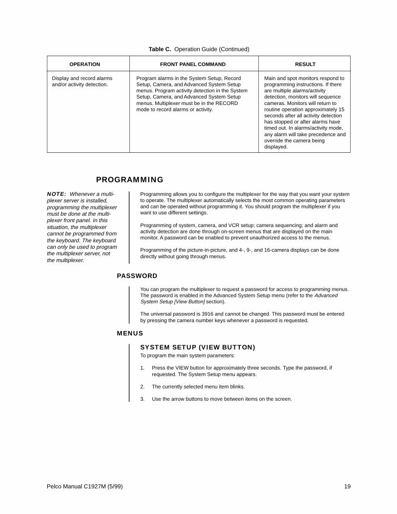
Table C. Operation Guide (Continued)
RESULT
Sequences all active cameras inthe PIP display.
Stops the sequence. The monitordisplays video from the camera onwhich the sequence stops.
Stops a sequence if one is in pro-gress. Displays a 2X or 4X zoom ofthe camera selected on the mainmonitor.
Records all cameras connected tothe multiplexer.
Displays the recorded cameras inthe selected format on the mainmonitor.
Deactivates the alarm.
Deactivates the alarms.
Deactivates the alarm.
Deactivates the alarms.
Displays or removes alarm list onthe main monitor.
Deactivate alarm(s) forcamera displayed on themain monitor
Deactivate alarm(s) forcamera displayed on thespot monitor.
Open or close a log of the last20 alarms.
Pelco Manual C1927M (5/99) 19
PROGRAMMING
Programming allows you to configure the multiplexer for the way that you want your systemto operate. The multiplexer automatically selects the most common operating parametersand can be operated without programming it. You should program the multiplexer if youwant to use different settings.
Programming of system, camera, and VCR setup; camera sequencing; and alarm andactivity detection are done through on-screen menus that are displayed on the mainmonitor. A password can be enabled to prevent unauthorized access to the menus.
Programming of the picture-in-picture, and 4-, 9-, and 16-camera displays can be donedirectly without going through menus.
PASSWORD
You can program the multiplexer to request a password for access to programming menus.The password is enabled in the Advanced System Setup menu (refer to the AdvancedSystem Setup [View Button] section).
The universal password is 3916 and cannot be changed. This password must be enteredby pressing the camera number keys whenever a password is requested.
MENUS
SYSTEM SETUP (VIEW BUTTON)To program the main system parameters:
1. Press the VIEW button for approximately three seconds. Type the password, ifrequested. The System Setup menu appears.
2. The currently selected menu item blinks.
3. Use the arrow buttons to move between items on the screen.
NOTE: Whenever a multi-plexer server is installed,programming the multiplexermust be done at the multi-plexer front panel. In thissituation, the multiplexercannot be programmed fromthe keyboard. The keyboardcan only be used to programthe multiplexer server, notthe multiplexer.
Table C. Operation Guide (Continued)
OPERATION FRONT PANEL COMMAND RESULT
Display and record alarmsand/or activity detection.
Program alarms in the System Setup, RecordSetup, Camera, and Advanced System Setupmenus. Program activity detection in the SystemSetup, Camera, and Advanced System Setupmenus. Multiplexer must be in the RECORDmode to record alarms or activity.
Main and spot monitors respond toprogramming instructions. If thereare multiple alarms/activitydetection, monitors will sequencecameras. Monitors will return toroutine operation approximately 15seconds after all activity detectionhas stopped or after alarms havetimed out. In alarms/activity mode,any alarm will take precedence andoverride the camera beingdisplayed.

20 Pelco Manual C1927M (5/99)
4. When the menu item you desire is highlighted (blinking), do one of the following:
• If a menu item has more than one option, press the +/- button to cycle throughthe options to select the one you want.
• If a menu item has only one option, press the +/- button to select it.
Time and DateSet the current time and date. The time uses a 24-hour clock.
Time DisplayON - Displays the time on the main monitor.OFF - The time is not shown on the main monitor.
Title DisplayON - Displays camera titles on the main monitor.OFF - Camera titles are not shown on the main monitor.
Record SpeedsSets the speed at which the VCR normally records video and the speed at which itrecords when there is an alarm(s). Setting the speeds in the System Setup menu alsosets the speeds in the Record Setup and Custom VCR Setup menus.
Main Monitor DisplayThe options are High Resolution or Reduced Flicker. Reduced Flicker can be selectedwhen there is flickering on the monitor screen, such as from a neon light. This is morevisible to the eye in PAL format multiplexers.
Global SetupsVideo TerminationsThese settings set the terminations for all video inputs. To set individual inputs, referto the Camera Setup section.
Set to 75 OHM when all equipment is connected only to the video IN connectors.
Set to LOOP HI-Z when all equipment is connected to the video OUT (looping) connec-tors. Equipment connected to the looping connectors must be terminated at 75 ohms.
Figure 11. Basic System Setup Menu
2/6/8 Hr2/6/8 Hr
MAIN MONITOR DISPLAY
RESET ACTIVITY DETECTION ALL CH TO
*2,6,or 8 Hr 120 Hr12 Hr 168 Hr16 Hr 180 Hr18 Hr 240 Hr24 Hr 360 Hr48 Hr 480 Hr72 Hr 600 Hr84 Hr 720 Hr96 Hr 960 Hr
HIGH RESOLUTION
HIGH RESOLUTIONREDUCED FLICKER
* 2/6/8 HR FOR NTSC/EIA MODEL MULTIPLEXERS, 3 HR FOR PAL/ CCIR MODELS. REMAINING RECORD SPEEDS DEPEND UPON VCR MODEL.
3
TIP: In any menu you canreverse the direction inwhich the options cycle bydouble-pressing the +/- but-ton.
TIP: You can exit a menuby pressing the correspond-ing button for approximatelythree seconds as you did toenter the menu.
NOTE: Title Display showsa maximum of 12 charactersin all modes except 16-cam-era display, in which only 9characters are shown.

Pelco Manual C1927M (5/99) 21
NO CHANGE - This is a pass-through selection in case you unintentionally hit the +/-button. This is not an undo button.
Alarm InputsRefer to the Alarms section for an explanation of normally closed and normally openoperation.
Dwell RatesSets the sequence dwell rate for all cameras. To set individual dwell rates for cameras,refer to the Sequence Setup section.
Activity DetectionENABLED/DISABLED - Turns activity detection on or off for all video inputs. To setindividual inputs, refer to the Camera Setup section.
NO CHANGE - This is a pass-through selection in case you unintentionally hit the +/-button. This is not an undo button.
5. When you have completed all the changes you want to make, go to EXIT or AD-VANCED SETUP.
6. Press the +/- button to exit the programming mode or to go to the advanced systemsetup menu.
When HELP is highlighted, you may press the +/- button to display a help screen that willtell you which buttons to press to configure specific options.
ADVANCED SYSTEM SETUP (VIEW BUTTON)To program the advanced main system parameters:
1. Press the VIEW button for approximately three seconds. The basic System Setupmenu appears.
2. The currently selected menu item blinks. Use the arrow buttons to highlight AD-VANCED SETUP.
3. Press the +/- button.
4. The Advanced System Setup menu appears.
5. Use the arrow buttons to move between items on the screen.
6. When the menu item you desire is highlighted (blinking), press the +/- button to cyclethrough the options.
Figure 12. Advanced System Setup Menu
ALL COLORCOLOR & B/WRESERVED
DATE FORMAT MM-DD-YYPASSWORD DISABLEDFRONT PANEL CONTROL ENABLED
MAIN MONITOR DISPLAYRESPONDS TO NONE
SPOT MONITOR DISPLAY SEQUENCERESPONDS TO ALARMS
CAMERA TYPES ALL COLOR
UNIT ID 001COMM. TYPE MASTER (KBD-T/D)
RELAY OUTPUT ALARM
MASTER (KBD-T/D)SLAVE
001–240
BLANKSEQUENCETRACK MAIN

22 Pelco Manual C1927M (5/99)
Date FormatSets the format for displaying the date on the main monitor.
PasswordEnables or disables password control to access programming menus.
Front Panel ControlEnables or disables the front panel buttons to operate the multiplexer. In either modeyou can access programming menus.
Main Monitor DisplaySelect ALARMS, ACTIVITY, or ALARMS/ACTIVITY if you want the main monitor toswitch to cameras that have alarms or activity detection. If you are using the mainmonitor for normal video and you do not want alarms or activity detection to overridewhat you are observing, select NONE.
Spot Monitor DisplayIf you want the spot monitor to switch to cameras that have alarms or activitydetection, select BLANK, SEQUENCE, or TRACK MAIN, then under RESPONDS TOselect ALARMS, ACTIVITY, or ALARMS/ACTIVITY. If you are using the spot monitorfor normal video and you do not want alarms or activity detection to override what youare observing, select NONE.
BLANK - Allows you to view an individual camera, but you cannot run a sequence. Analarm or activity detection will override the camera you are viewing. When the alarm oractivity detection goes away, the screen will return to the camera you were viewing.
SEQUENCE - Allows you to view an individual camera or run a sequence. An alarm oractivity detection will override what you are observing. When the alarm or activitydetection goes away, the screen will return to the camera or sequence you were viewing.
TRACK MAIN - The spot monitor will follow the camera switching that occurs on themain monitor. This feature is used only when a KBD4000 keyboard is connected to themultiplexer for controlling moveable cameras.
Camera TypesThe COLOR & B/W setting allows the multiplexer to adapt to the combination of bothcolor and monochrome video signals. The switching speed of the multiplexer is not asfast when it has to change formats between monochrome and color cameras. Formonochrome models, you will not receive color from a color camera except inRECORD mode. The RESERVED setting can improve performance when usingcameras with non-standard sync or poor video quality.
Unit IDThis is the address of the multiplexer. If your system has more than one multiplexer,each multiplexer must have its own address.
Comm. TypeIf your system has an MX4000SVR Genex™ Multiplexer Server and/or a KBD4000Genex™ Multiplexer Keyboard, one multiplexer (any one) must be the master. Onlyone multiplexer can be the master. All other multiplexers must be slaves. The mastermultiplexer communicates between the server and the slave multiplexers. If there isonly one multiplexer connected to a server, it must be the master. The KBD4000keyboard communicates with the multiplexer only when the multiplexer is in its defaultsetting of MASTER (KBD-T/D).
Relay OutputOperates the relay on the back of the multiplexer. The relay is used to change theVCR to its alarm recording speed (refer to the Alarms section).
7. When you have completed all the changes you want to make, go to EXIT or BASICSETUP.
8. Press the +/- button to exit the programming mode or to go to the basic system setupmenu.
When HELP is highlighted, you may press the +/- button to display a help screen that willtell you which buttons to press to configure specific options.
NOTE: Remember, onemultiplexer must be themaster. The default settingis Master (KBD-T/D).
NOTE: In the alarms mode,an alarm signal is producedwhen a remote switch opensor closes a ground in themultiplexer; for example, if aswitch is on a door and thedoor is opened (refer to theAlarms section). In the activ-ity mode, the multiplexercontinually monitors selectedcamera inputs for motion.When motion is detected,the multiplexer increases thefrequency with which thatcamera(s) is shown and re-corded. Activity detection ismost effective when only afew cameras are showingactivity (refer to the CameraSetup section).

Pelco Manual C1927M (5/99) 23
RECORD SETUP (DISPLAY/RECORD BUTTON)To program the VCR recording parameters:
1. Press the DISPLAY/RECORD button for approximately three seconds. Type thepassword, if requested. The Record Setup menu appears.
2. The currently selected menu item blinks.
3. Use the arrow buttons to move between items on the screen.
4. When the menu item you desire is highlighted (blinking), press the +/- button to cyclethrough the options to select the one you want.
Record SpeedsSets the speed at which the VCR normally records video and the speed at which itrecords when there is an alarm(s). Setting the speeds in the Record Setup menu alsosets the speeds in the System Setup and Custom VCR Setup menus.
VCR TypeSee Table D. If your VCR is not listed among the options, do either of the following:
• Select UNIVERSAL. In the recording speed menu item at the top of the screen,select an option that your VCR will support.
• Select CUSTOM. Then go to CONFIGURE CUSTOM VCR and press the +/-button to go to the Custom VCR Setup menu. The switch interval can bechanged only while in this setting.
VCR Video FormatComposite is standard video on a coaxial cable. SVHS is higher resolution video on aspecial cable. This feature is not available on monochrome units.
VCR Switch PulseENABLED means the multiplexer waits for a head switching pulse from the VCR. If themultiplexer does not get a pulse from the VCR (because of a broken wire or the VCRdoes not give a pulse in some modes), it may appear that the multiplexer is notworking properly.
DISABLED means the VCR head switching pulse is not used.
Alarm HandlingDetermines how alarms are recorded and for how long.
AS A PRIORITY updates and records camera(s) with an alarm more often thancamera(s) without an alarm.
ONLY records only camera(s) with an alarm.
Configure Custom VCRPress the +/- button to get to the CUSTOM VCR SETUP menu.
Playback FormatTapes made using Pelco, Robot, and DM multiplexers can be played.
5. When you have completed all the changes you want to make, go to EXIT.
6. Press the +/- button to exit the programming mode.
When HELP is highlighted, you may press the +/- button to display a help screen that willtell you which buttons to press to configure specific options.

24 Pelco Manual C1927M (5/99)
Table D. VCR Types
NTSC PAL
UNIVERSAL UNIVERSAL
GYYR TLC1800 ASUTSA TLVCR 251
GYYR 2100 ASUTSA TLVCR 964
GYYR 2100 HD MODE BURLE TC3910X
JVC SR-L900U HITACHI VTL30E
JVC SR-L901U HITACHI VT-L1000E
JVC SR-9070U HITACHI VT-L2000E
JVC BR-S925U JVC BR9060E
MITSUBISHI HS7424U JVC BR-S920/925
MITSUBISHI HS7496U JVC SR-L900E
MITSUBISHI HS5168U MITS. HS5300/5600
MITS. HS7168U NORM MITS. HS5424E
MITS. HS7168U HD PANAS. AG6024/6124
PANASONIC AG-RT600 PANASONIC AG6720
PANASONIC AG6124 PANASONIC AG6730
PANASONIC AG6730 PANASONIC AG6040
PELCO TLR2024 SANYO TLS900P
PELCO TLR2096 SANYO TLS1000
PELCO TLR2168 NORM SANYO SRT-500P
PELCO TLR2168 HD SANYO TLS2000
SANYO SRT600 SONY SVT100P
SANYO TLS924/972 SONY SVT5000P
SANYO TLS2500/7000 CUSTOM
TOSHIBA KV6300
TOSHIBA KV7024A
TOSHIBA KV7168A
TOSHIBA KV7960A
TOSHIBA KV8168A
CUSTOM
Figure 13. Basic VCR Settings Menu
****
ALARM DURATION30 SECONDS1 MINUTE2 MINUTES5 MINUTES10 MINUTES15 MINUTES
ENABLEDDISABLED
*2,6,or 8 Hr 24 Hr 96 Hr 240 Hr 12 Hr 48 Hr 120 Hr 360 Hr 16 Hr 72 Hr 168 Hr 480 Hr 18 Hr 84 Hr 180 Hr 600 Hr 720 Hr 960 Hr
PELCOROBOTDM
SEE TABLE D
* 2/6/8 HR FOR NTSC/EIA MODEL MULTIPLEXERS, 3 HOUR FOR PAL/CCIR MODELS. REMAINING RECORD SPEEDS DEPEND UPON VCR MODEL. ** NOT SHOWN ON MONOCHROME MODELS.
NORMAL REC. SPEED 2/6/8 HrALARM REC. SPEED 2/6/8 Hr
VCR SETUP
VCR TYPE UNIVERSALVCR VIDEO FORMAT COMPOSITEVCR SWITCH PULSE DISABLED
ALARM HANDLING
RECORD ALARMS AS A PRIORTIYALARM RECORD TIME ALARM DURATION
CONFIGURE CUSTOM VCR
PLAYBACK FORMAT PELCO

Pelco Manual C1927M (5/99) 25
Figure 14. Custom VCR Setup Menu
CUSTOM VCR SETUP (DISPLAY/RECORD BUTTON)To program the advanced VCR parameters:
1. Press the DISPLAY/RECORD button for approximately three seconds. The RecordSetup menu appears.
2. Make sure the VCR Type in the Record Setup menu is set to CUSTOM.
3. The currently selected menu item blinks. Use the arrow buttons to highlight CONFIG-URE CUSTOM VCR.
4. Press the +/- button.
5. The Custom VCR Setup menu appears.
6. Use the arrow buttons to move between items on the screen.
7. When the menu item you desire is highlighted (blinking), press the +/- button to cyclethrough the options.
Record SpeedsSets the speed at which the VCR normally records video and the speed at which itrecords when there is an alarm(s).
Setting the speeds in the Custom VCR Setup menu also sets the speeds in theSystem Setup and Record Setup menus.
IntervalInterval is the number of fields recorded by the VCR before switching to the next camera.
8. When you have completed all the changes you want to make, go to EXIT or BACK.
9. Press the +/- button to exit the programming mode or to return to the Record Setup menu.
When HELP is highlighted, you may press the +/- button to display a help screen that willtell you which buttons to press to configure specific options.
NOTE: For proper record-ing, the switching rate of themultiplexer must match thatof the VCR. If they do notmatch, the VCR may skipframes or record duplicateframes.
NORMAL RECORD SETUP
RECORD SPEED 2/6/8 HrSWITCH INTERVAL 003
ALARM RECORD SETUP
RECORD SPEED 2/6/8 HrSWITCH INTERVAL 003
EXIT BACK
003 TO 509**
*2,6,or 8 Hr 120 Hr12 Hr 168 Hr16 Hr 180 Hr18 Hr 240 Hr24 Hr 360 Hr48 Hr 480 Hr72 Hr 600 Hr84 Hr 720 Hr96 Hr 960 Hr
* 2/6/8 HR FOR NTSC/EIA MODEL MULTIPLEXERS, 3 HR FOR PAL/CCIR MODELS.REMAINING RECORD SPEEDS DEPEND UPON VCR MODEL.
** VCR TYPE IN RECORD SETUP MENU MUST BE SET TO CUSTOM IN ORDER TOMAKE SELECTIONS.

26 Pelco Manual C1927M (5/99)
CAMERA SETUP (CAMERA BUTTONS)To program a camera input:
1. Press the desired CAMERA button for approximately three seconds. Type thepassword, if requested. The Camera menu appears. A video insert appears that showswhat the camera is viewing. This is useful to make sure you have selected the correctcamera and to see what effect there is on the video when you select a menu option.
2. The currently selected menu item blinks.
3. Use the arrow buttons to move between items on the screen.
4. When the menu item you desire is highlighted (blinking), press the +/- button to cyclethrough the options to select the one you want. Use the right arrow button to advanceto the next character position when titling a camera.
Video TerminationSet to 75 OHM when equipment is connected only to the video IN connector.
Set to LOOP HI-Z when equipment is connected to the video OUT (looping) connec-tor. Equipment connected to the looping connector must be terminated at 75 ohms.
Alarm InputRefer to the Alarms section for an explanation of normally closed and normally openoperation.
Coaxitron® FormatEXTENDED - Use when your system has moveable cameras controlled by 32-bitCoaxitron® receivers, such as Esprit™, Intercept®, Spectra®, and LRD41C21/LRD41C22 Series.
OFF - Use when your system has fixed cameras only.
STANDARD - Use when your system has moveable cameras controlled by 15-bitCoaxitron® receivers, such as the CX9000 Series, the PT7700, and the ED25/27/28/29.
Figure 15. Basic Camera Menu
OPENCLOSEDDISABLED
VIDEO INPUT TERMINATION 75 OHMALARM INPUT NORMALLY OPENCOAXITRON FORMAT EXTENDED
ACTIVITY DETECTION ENABLEDSET DETECTION MASK
ENABLEDDISABLED
*
* ONLY NINE CHARACTERS APPEAR WHEN IN THE 16-CAMERA DISPLAY.
EXTENDEDOFFSTANDARD
(HYPHEN)

Pelco Manual C1927M (5/99) 27
Activity DetectionA camera can be set to respond or not to respond to motion. If enabled, select SETDETECTION MASK to define what part of the camera’s viewing field will be monitoredfor motion.
5. To program another camera, press the button for that camera. Repeat steps 2-4.
6. When you have completed all the changes you want to make, go to EXIT.
7. Press the +/- button to exit the programming mode.
When HELP is highlighted, you may press the +/- button to display a help screen that willtell you which buttons to press to configure specific options.
ACTIVITY MASK SETUPActivity detection continually monitors selected camera inputs for motion. When motion isdetected, the multiplexer increases the frequency with which that camera(s) is shown andrecorded. Activity detection is most effective when only a few cameras are showing activity.As the number of cameras with activity increases, the slower the frequency at which theycan be shown and recorded. If all 16 cameras show activity, there will be virtually noincrease.
The activity mask selects that portion or portions of the camera’s field of view that themultiplexer will monitor for motion. The entire grid is active on default.
To program an activity mask for a camera:
1. Press the desired CAMERA button for approximately three seconds. The Cameramenu appears.
2. The currently selected menu item blinks. Use the arrow buttons to highlight SETDETECTION MASK.
3. Press the +/- button. The Activity Mask appears.
4. The currently selected menu item or activity box blinks.
5. Use the arrow buttons to move between menu items and activity boxes on the screen.
6. Highlight the sensitivity menu item. Press the +/- button to select the sensitivity. Thehigher the sensitivity is, the less the amount of motion that will be needed to detectactivity.
Figure 16. Activity Dectection Mask
ACTIVITY DETECTION MED SENSITIVITY
SET ALL CLEAR ALL EXIT TEST
ACTIVITY BOX SET
ACTIVITY BOX CLEAR
LOW SENSITIVITYMED SENSITIVITYHIGH SENSITIVITY

28 Pelco Manual C1927M (5/99)
7. Turn activity boxes on or off.
To turn on all activity boxes, use the arrow buttons to choose SET ALL. Press the +/-button. All boxes will contain a symbol as shown in Figure 16. The multiplexer willmonitor motion in those boxes.
To turn off all activity boxes, use the arrow keys to choose CLEAR ALL. Press the +/-button. All boxes will be blank.
To turn on or off an individual box, use the arrow keys to select the box. Press +/-button to toggle a box on or off.
Turn off activity boxes where you want motion ignored, such as blowing trees,highways, computer monitors, fluorescent lighting, and non-problem areas. Anexample of a non-problem area would be a camera focused on a bank vault entrancebut ignoring tellers working nearby.
8. To test the activity detection, highlight TEST and press the +/- button.
Create motion in front of the camera. Small black and white dashes will flash wheremotion is detected.
To exit the test mode, press the +/- key to return to the mask.
9. If you did not like what you saw in the test mode, change the mask and test the activitydetection again.
10. When you finish defining the activity mask, go to EXIT. Press the +/- button to exit theprogramming mode.
11. If necessary, repeat steps 1-10 to program the activity mask for other cameras.
SEQUENCE SETUP (SEQUENCE BUTTON)Sequencing can be programmed in full screen, four-camera and nine-camera displays. Thecameras will not sequence when operating the zoom function. The LED(s) above thecamera button(s) will illuminate to indicate which camera(s) is being displayed.
To program camera sequencing:
1. Press the SEQUENCE button for approximately three seconds. Type the password, ifrequested. The Sequence menu appears.
2. The currently selected menu item blinks.
3. Use the arrow buttons to move between items on the screen.
4. When the menu item you desire is highlighted (blinking), press the +/- button to cyclethrough the options to select the one you want.
5. When you have completed all the changes you want to make, go to EXIT.
6. Press the +/- button to exit the programming mode.
When HELP is highlighted, you may press the +/- button to display a help screen that willtell you which buttons to press to configure specific options.

Pelco Manual C1927M (5/99) 29
HELP MENUThe Help menu is accessed from any other menu.
1. Use the up and down arrow buttons in any menu to highlight HELP.2. Press the +/- button. The Help menu appears.
Figure 18. Help Menu
GROUP QUAD (2x2)1 042 043 044 04
NINE (3x3)0404
DISP/RECBUTTON SETTING
VCR SPEED & ALARM
QUICK SETUP
MONITOR SETUP
HELP
+/– - SINGLE PRESS MODIFY DOUBLE PRESS CHANGE EDIT DIRECTION
HOLD BUTTONS TO ENTER/EXITTHEIR ASSOCIATED MENU
USE ARROWS TO NAVIGATE
Figure 17. Camera Sequence Menu
MULTIPLE CAMERA DISPLAY SETUP
The multiple camera display formats may be configured using the front panel controls. TheLEDs above the camera buttons will illuminate to indicate which cameras are being displayed.
PROGRAMMING THE PICTURE-IN-PICTURE DISPLAY( BUTTON)The on-screen location and size of the picture-in-picture (PIP) display are programmable.PIP is not available in VCR or RECORD modes.
To program the PIP display:
1. Press the button.
2. Press the button (for approximately three seconds) until the message PROGRAMPIP SIZE appears.
3. Use the arrow buttons to increase or decrease the PIP display size.4. Press the +/- button. The message PROGRAM PIP POSITION appears.5. Use the arrow buttons to move the PIP display location.6. Press the +/- button to exit the PIP programming menu.

30 Pelco Manual C1927M (5/99)
PROGRAMMING THE 4-CAMERA DISPLAYS ( BUTTON)You can program four groups of four cameras each. Each of the four groups can beprogrammed to include any four cameras. is not available in RECORD mode.
To program the four-camera displays:
1. Press the button to call up a four-camera display. If necessary, press the button again to advance to the four-camera group that you wish to configure.
2. Press the button for approximately three seconds. A bar will appear in the firstcamera location of the four-camera display, indicating that you are in the programmingmode.
3. Use the arrow buttons to move to each camera location in the four-camera display.
4. When the camera location that you desire is highlighted, choose the new camera bypressing the camera button for the desired camera.
5. To exit the programming mode, press any arrow button as many times as necessaryuntil the bar moves off the screen.
6. If necessary, repeat steps 1-5 to program another group.
PROGRAMMING THE 9-CAMERA DISPLAYS ( BUTTON)You can program two groups of nine cameras each. Both groups can be programmed toinclude any nine cameras. is not available in RECORD mode.
To program the nine-camera displays:
1. Press the button to call up a nine-camera display. If necessary, press the button again to advance to the other nine-camera group.
2. Press the button for approximately three seconds. A bar will appear in the firstcamera location of the nine-camera display, indicating that you are in the programmingmode.
3. Use the arrow buttons to move to each camera location in the nine-camera display.
4. When the camera location that you desire is highlighted, choose the new camera bypressing the camera button for the desired camera.
5. To exit the programming mode, press any arrow button as many times as necessaryuntil the bar moves off the screen.
6. If necessary, repeat steps 1-5 to program the second group.
PROGRAMMING THE 16-CAMERA DISPLAY ( BUTTON) is not available in RECORD mode.
To program the 16-camera display:
1. Press the button to call up the 16-camera display.
2. Press the button for approximately three seconds. A bar will appear in the firstcamera location of the 16-camera display, indicating that you are in the programmingmode.
3. Use the arrow buttons to move to each camera location in the 16-camera display.
4. When the camera location that you desire is highlighted, choose the new camera bypressing the camera button for the desired camera.
5. To exit the programming mode, press any arrow button as many times as necessaryuntil the bar moves off the screen.
NOTE: All active camerasmay be sequenced in onelocation of a 4-, 9-, or 16-camera display mode. Whilein a multiple-camera displaymode, use the arrow buttonsto move the on-screen barto the camera location forsequencing. Press the se-quence button to initiatesequencing of all activecameras. Refer to the Op-eration Guide table also.

Pelco Manual C1927M (5/99) 31
PROGRAMMING MENU DEFAULTS
Table E. Programming Menu Defaults
Menu Item Default
System Setup Time Display OnTitle Display OnNormal Record Speed 2/6/8 Hr (NTSC/EIA)
3 Hr (PAL/CCIR)Alarm Record Speed 2/6/8 Hr (NTSC/EIA)
3 Hr (PAL/CCIR)Main Monitor Display High ResolutionReset All Video Terminations To 75 OhmReset All Alarm Inputs To Normally OpenedReset All Seq Dwell Rates To 02Reset Activity Detection All Ch To Enabled
Advanced System Date Format MM-DD-YY (NTSC/EIA)Setup DD-MM-YY (PAL/CCIR)
Password DisabledSystem Password 3916Front Panel Control EnabledMain Monitor Display Responds To NoneSpot Monitor Display SequenceResponds To AlarmsCamera Types All ColorUnit ID 001Comm. Type Master (KBD-T/D)Relay Output Alarm
Record Setup Normal Rec. Speed 2/6/8 Hr (NTSC/EIA)3 Hr (PAL/CCIR)
Alarm Rec. Speed 2/6/8 Hr (NTSC/EIA)3 Hr (PAL/CCIR)
VCR Type UniversalVCR Video Format CompositeVCR Switch Pulse DisabledRecord Alarms As A PriorityAlarm Record Time Alarm DurationPlayback Format Pelco
Custom VCR Normal Record Speed 2/6/8 Hr (NTSC/EIA)Setup 3 Hr (PAL/CCIR)
Normal Switch Interval 003Alarm Record Speed 2/6/8 Hr (NTSC/EIA)
3 Hr (PAL/CCIR)Alarm Switch Speed 003
Camera Title Camera NumberVideo Input Termination 75 OhmAlarm Input Normally OpenCoaxitron Format ExtendedActivity Detection Enabled
Activity Detection Sensitivity MedActivity Boxes Set All
Sequence Individual Camera Dwell Time 02Quad (2x2) Dwell Time 04Nine (3x3) Dwell Time 04

32 Pelco Manual C1927M (5/99)
TROUBLESHOOTING
If you have difficulty operating your system, run through the following checklist to see if youcan solve the problem.
1. Are the keyboard switches set properly?
2. Is the equipment wired properly?
3. Are the menu options in the multiplexer(s) and server set properly?
4. Has the multiplexer been set to the correct mode using the DISPLAY/RECORD button?
5. The main monitor will display multiple screen images. The spot monitor displays fullscreen views only.
6. SPOT MONITOR must be selected to operate presets, patterns, and auxiliaries.
7. Tape playback can be done only on the main monitor while in the VCR mode.
8. Moveable cameras must be Coaxitron® compatible and the proper Coaxitron® formatselected in the Camera menu of the multiplexer. If the proper format is not selected,the camera will either not move or have sluggish control.
9. Moveable cameras can be operated with the joystick only if the spot monitor is pro-grammed to track the main monitor or SPOT MONITOR is chosen. The camera willmove on the main monitor if the same camera is being shown on both the main andspot monitors.
10. The position of switch 7 on the keyboard determines how you call cameras.
If the switch is ON, all cameras are addressed consecutively. Do not count just thecameras installed. Count 16 camera inputs per multiplexer, even if a multiplexer has only9 inputs. The first input of multiplexer 1 is always camera 1, the first input of multi-plexer 2 is always camera 17, the second input of multiplexer 3 is always camera 34.
If the switch is OFF, cameras are addressed in groups of 9 or 16 according to theaddress of the multiplexer. Select a multiplexer (for example, number 3), then choosea camera (1-9 or 1-16).
11. If you have one multiplexer, it must be the master. If you have more than onemultiplexer, one of them (any one) must be the master and all the others slaves(Advanced System Setup menu of multiplexer).
12. If you have more than one multiplexer, they must have different addresses (AdvancedSystem Setup menu of multiplexer).
13. If you have a server, the address of the multiplexer must correspond to the input it isconnected to on the server. For example, if the multiplexer goes to input 4 on theserver, the multiplexer must be address 4.
14. If you have a server, each keyboard must have its own address.
15. If you have a server, each keyboard controls its corresponding monitor(s). In theSINGLE mode, keyboard 1 controls monitor 1, keyboard 2 controls monitor 2, etc. Inthe PAIRED mode, keyboard 1 controls monitor 1 (main) and monitor 2 (spot), andkeyboard 3 controls monitor 3 (main) and monitor 4 (spot). In the paired mode,keyboards 2 and 4 are not used.
16. If you have a server and cannot change between full screen and multiple screen viewson the main monitor, check the MAIN MONITOR CONTROL setting in the Monitormenu of the server.
17. Adjust head tracking control on the VCR until the picture stabilizes if:
a. the picture appears jittery when multiplexer is in VCR playback mode, or
b. one camera view sequences out of order when the multiplexer is in multi-screenVCR playback mode.

Pelco Manual C1927M (5/99) 33
RESETTo reset the multiplexer:
1. Unplug the power cord.
2. Press and hold the VIEW button on the front panel of the multiplexer while you plugthe power cord into an electrical outlet. When the Initialization Menu appears, releasethe VIEW button. The monitor will indicate PLEASE WAIT and begin a 20-secondcountdown. When the countdown has been completed, the Initialization Menu willdisappear, all programming menus will be at their default settings, and the multiplexerwill be ready for use.
3. Reprogram the multiplexer. Refer to the Programming section.
SPECIFICATIONS
VIDEOInput Level: 1 Vp-p, composite
NTSC: 525 lines, 60 fields/second
PAL: 625 lines, 50 fields/second
Digital Image: 768(H) x 512(V) pixels full screen, 1536 bytes horizontal memory,26 MB display image memory, 8-bit luminance, 256 shades of gray8-bit chrominance, over 16 million colors
Format: CCIR 601 4:2:2Sampling Rate: 13.5 MHzGeometric Error: Less than 1 percent, all modesResizing: Multi-element horizontal and vertical finite impulse response
Analog ProcessingBandwidth: 20 MHzDifferential Phase: Less than 2 degreesDifferential Gain: Less than 2 percent
Character Generator: Programmable, bit mapped
ELECTRICALOperating Voltage: 120 VAC (+15/-30%), 50/60 Hz or
230 VAC (+15/-30%, 50/60 Hz
Power: Less than 25 watts
Video Inputs: Nine or sixteenBNC, looping with programmable termination, 75 ohms or Hi-Z
Monitor Outputs: TwoMain: BNC, 75 ohmsSpot: BNC, 75 ohms
VCR Inputs: OneVCR In: BNC, composite, 75 ohms
4-pin mini-DIN, YC input (SVHS)
VCR Outputs: OneVCR Out: BNC, composite, 75 ohms
4-pin mini-DIN, YC input (SVHS)
Alarm Inputs: Sixteen individually programmable for NO or NC
Alarm Output: One Form-C relay, 0.5 A continuous, 1.0 A momentary
GENERALOperatingTemperature: 32° to 122°F (0° to 50°C)
Relative Humidity: 90% (non-condensing)
Construction: Aluminum
Finish: Black
Dimensions: 1.75" H x 17.2" W x 12.2" D(4.45 cm x 43.69 cm x 30.99 cm)
Weight: Unit Shipping10.6 lb (4.80 kg) 14 lb (6.35 kg)
(Design and product specifications subject to change without notice.)

34 Pelco Manual C1927M (5/99)
REVISION HISTORY
Manual # Date CommentsC1927M 3/99 Preliminary version released for beta evaluation.
5/99 Original version.
® Pelco and the Pelco logo are registered trademarks of Pelco. © Copyright 1999, Pelco. All rights reserved.
WARRANTYPelco will repair or replace, without charge, any merchandise proved defectivein material or workmanship for a period of one year after the date of shipment.Exceptions to this warranty are as noted below:
• Three years on Genex™ Series (multiplexers, server, and keyboard).• Two years on all standard motorized and fixed focal length lenses.• Two years on Esprit™, Legacy®, Intercept®, PV1000 Series, CM6700/
CM8500/CM9500/CM9750/CM9760 Matrix, Spectra®, DF5 Series and DF8Fixed Dome products.
• Two years on WW5700 series window wiper (excluding wiper blades).• Two years on cameras.• Six months on all pan and tilts, scanners or preset lenses used in continu-
ous motion applications (that is, preset scan, tour and auto scan modes).
Pelco will warrant all replacement parts and repairs for 90 days from the date ofPelco shipment. All goods requiring warranty repair shall be sent freight prepaidto Pelco, Clovis, California. Repairs made necessary by reason of misuse, al-teration, normal wear, or accident are not covered under this warranty.
Pelco assumes no risk and shall be subject to no liability for damages or lossresulting from the specific use or application made of the Products. Pelco’sliability for any claim, whether based on breach of contract, negligence, infringe-ment of any rights of any party or product liability, relating to the Products shallnot exceed the price paid by the Dealer to Pelco for such Products. In no eventwill Pelco be liable for any special, incidental or consequential damages (includ-ing loss of use, loss of profit and claims of third parties) however caused, whetherby the negligence of Pelco or otherwise.
The above warranty provides the Dealer with specific legal rights. The Dealermay also have additional rights, which are subject to variation from state to state.
If a warranty repair is required, the Dealer must contact Pelco at (800) 289-9100or (559) 292-1981 to obtain a Repair Authorization number (RA), and providethe following information:
1. Model and serial number2. Date of shipment, P.O. number, Sales Order number, or Pelco invoice number3. Details of the defect or problem
If there is a dispute regarding the warranty of a product which does not fallunder the warranty conditions stated above, please include a written explana-tion with the product when returned.
Ship freight prepaid to: Pelco300 West Pontiac WayClovis, CA 93612-5699
Method of return shipment shall be the same or equal to the method by whichthe item was received by Pelco.
RETURNSIn order to expedite parts returned to the factory for repair or credit, please callthe factory at (800) 289-9100 or (559) 292-1981 to obtain an authorization num-ber (CA number if returned for credit, and RA number if returned for repair).Goods returned for repair or credit should be clearly identified with the assignedCA/RA number and freight should be prepaid. All merchandise returned for creditmay be subject to a 20% restocking and refurbishing charge.
Ship freight prepaid to: Pelco300 West Pontiac WayClovis, CA 93612-5699
WARRANTY AND RETURN INFORMATION
REGULATORY NOTICES
Note: This equipment has been tested and found to comply with the limits of a Class Adigital device, pursuant to part 15 of the FCC rules. These limits are designed to providereasonable protection against harmful interference when the equipment is operated in acommercial environment. This equipment generates, uses, and can radiate radio frequencyenergy and, if not installed and used in accordance with the instruction manual, may causeharmful interference to radio communications. Operation of this equipment in a residentialarea is likely to cause harmful interference in which case the user will be required to correctthe interference at his own expense.