Embed Size (px)
Citation preview
NA
AM
S S
tan
da
rd
NAAMS Parts
NAAMS Parts
18001799
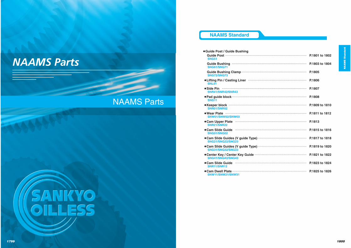
Guide Post / Guide Bushing
Guide Post ………………………………………………………………… P.1801 to 1802SNG51
Guide Bushing …………………………………………………………… P.1803 to 1804SNG61/SNG71
Guide Bushing Clamp …………………………………………………… P.1805SNG72/SNG73
Lifting Pin / Casting Liner ……………………………………………… P.1806SNL01
Side Pin …………………………………………………………………… P.1807SNR41/SNR42/SNR43
Pad guide block …………………………………………………………… P.1808SNG11
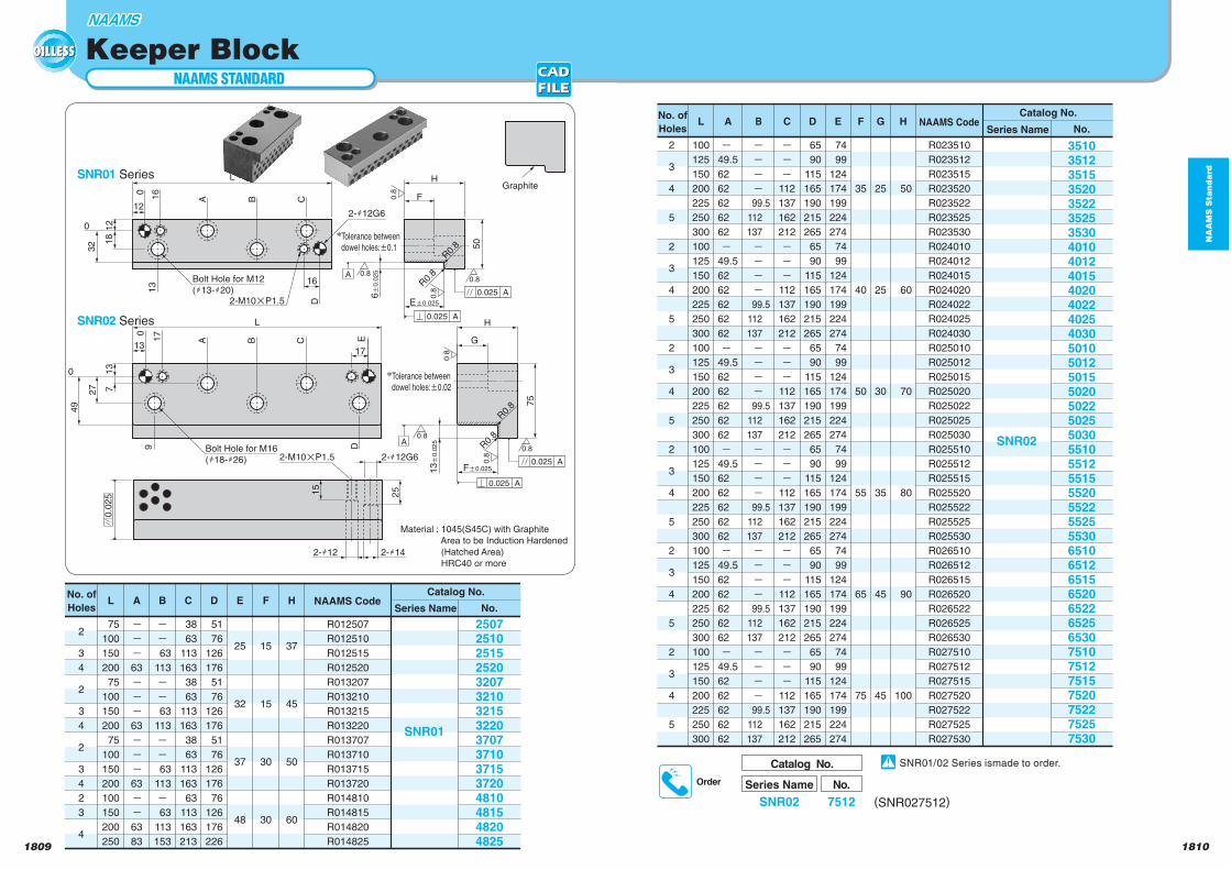
Keeper block ……………………………………………………………… P.1809 to 1810SNR01/SNR02
Wear Plate ………………………………………………………………… P.1811 to 1812SNW01/SNW02/SNW03
Cam Upper Plate ………………………………………………………… P.1813SNR21/SNR22
Cam Slide Guide ………………………………………………………… P.1815 to 1816SNG01/SNG02
Cam Slide Guides (V guide Type) ……………………………………… P.1817 to 1818SNG21/SNG22/SNG23
Cam Slide Guides (V guide Type) ……………………………………… P.1819 to 1820SNG31/SNG32/SNG33
Center Key / Center Key Guide ………………………………………… P.1821 to 1822SNG41/SNG42/SNG43
Cam Slide Guide ………………………………………………………… P.1823 to 1824SNR11/SNR12
Cam Dwell Plate …………………………………………………………… P.1825 to 1826SNW11/SNW21/SNW31
NAAMS Standard
NA
AM
S S
tan
da
rd
NAAMS STANDARD
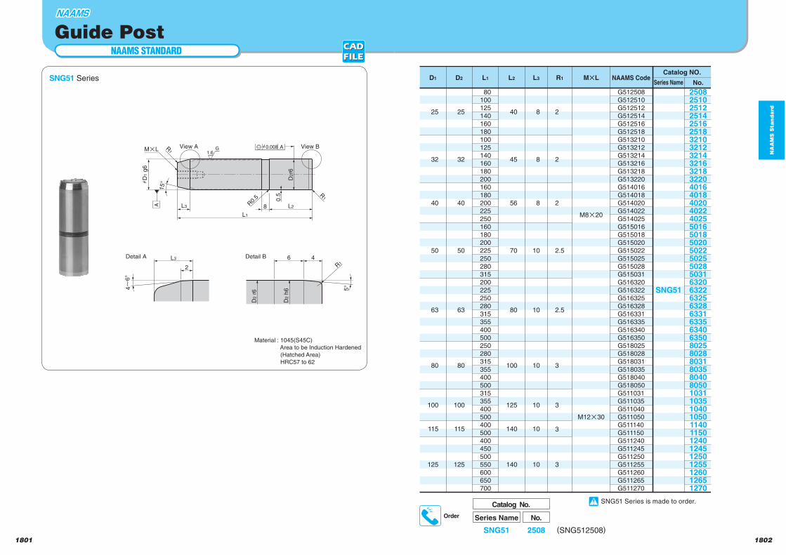
SNG51 Series
18021801
Guide Post
Series Name
Catalog No.
SNG51
No.
2508 (SNG512508)
Order
G1.6
0.5
2
L3
hD
1 g
6
R1
4~
6°
A
View B
R0.
5
8 L2
L1
15°
View A
Detail A Detail BL3 6 4
R1
5°
D2 h
6
D2 r
6
MpL Ah0.008
D2r6
R1
No.
G512508
G512510
G512512
G512514
G512516
G512518
G513210
G513212
G513214
G513216
G513218
G513220
G514016
G514018
G514020
G514022
G514025
G515016
G515018
G515020
G515022
G515025
G515028
G515031
G516320
G516322
G516325
G516328
G516331
G516335
G516340
G516350
G518025
G518028
G518031
G518035
G518040
G518050
G511031
G511035
G511040
G511050
G511140
G511150
G511240
G511245
G511250
G511255
G511260
G511265
G511270
2508
2510
2512
2514
2516
2518
3210
3212
3214
3216
3218
3220
4016
4018
4020
4022
4025
5016
5018
5020
5022
5025
5028
5031
6320
6322
6325
6328
6331
6335
6340
6350
8025
8028
8031
8035
8040
8050
1031
1035
1040
1050
114011501240124512501255126012651270
SNG51
25
32
40
50
63
80
100
115
125
D1
25
32
40
50
63
80
100
115
125
D2
80
100
125
140
160
180
100
125
140
160
180
200
160
180
200
225
250
160
180
200
225
250
280
315
200
225
250
280
315
355
400
500
250
280
315
355
400
500
315
355
400
500
400
500
400
450
500
550
600
650
700
L1
40
45
56
70
80
100
125
140
140
L2
8
8
8
10
10
10
10
10
10
L3
2
2
2
2.5
2.5
3
3
3
3
R1
M8p20
M12p30
MPLSeries Name
Catalog NO.NAAMS Code
Material : 1045(S45C)
Area to be Induction Hardened
(Hatched Area)
HRC57 to 62
SNG51 Series is made to order.
NA
AM
S S
tan
da
rd
18041803
NAAMS STANDARD
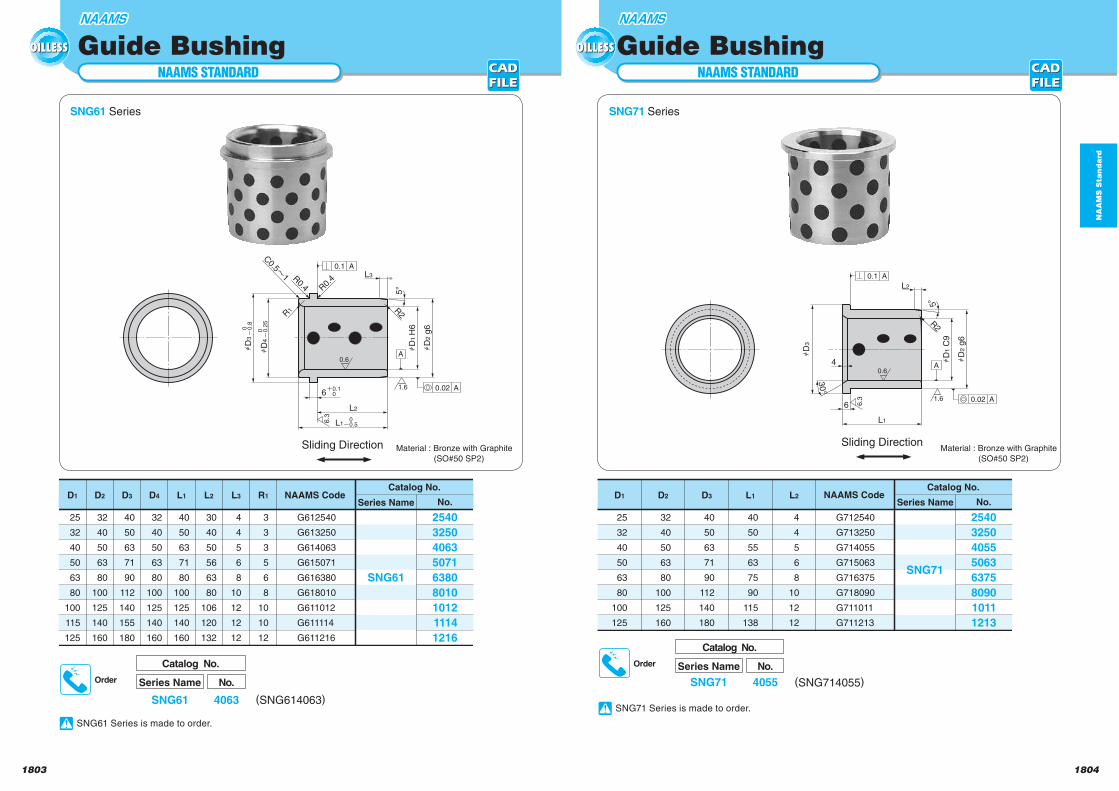
Guide BushingNAAMS STANDARD
Guide Bushing
SNG61 Series SNG71 Series
R2
C0.5n
1 R0.4 R0.
4
hD
4
hD
1 H
6
hD
2 g
6
hD
3
R1
L3
5°
L2
L1
6i0.1
0
0o0.5
A0.1
A0.02
A0.6
6.3
1.6
0o
0.2
5
0o
0.8
No.
G712540
G713250
G714055
G715063
G716375
G718090
G711011
G711213
2540
3250
4055
5063
6375
8090
1011
1213
Catalog No.
SNG71
40
50
55
63
75
90
115
138
L1
4
4
5
6
8
10
12
12
L2
40
50
63
71
90
112
140
180
D3
32
40
50
63
80
100
125
160
D2
25
32
40
50
63
80
100
125
D1Series Name
NAAMS Code Series Name No.
G612540
G613250
G614063
G615071
G616380
G618010
G611012
G611114
G611216
2540
3250
4063
5071
6380
8010
1012
1114
1216
Catalog No.
SNG61
NAAMS Code
25
32
40
50
63
80
100
115
125
D1
32
40
50
63
80
100
125
140
160
D2
40
50
63
71
90
112
140
155
180
D3
32
40
50
63
80
100
125
140
160
D4
40
50
63
71
80
100
125
140
160
L1
30
40
50
56
63
80
106
120
132
L2
4
4
5
6
8
10
12
12
12
L3
3
3
3
5
6
8
10
10
12
R1
Material : Bronze with Graphite
(SO#50 SP2)
Material : Bronze with Graphite
(SO#50 SP2)
Series Name
Catalog No.
SNG61
No.
4063 (SNG614063)
Order
Series Name
Catalog No.
SNG71
No.
4055 (SNG714055)
Order
6.3 1.6
0.6
30°
hD
3
hD
1 C
9
hD
2 g
6
4
L1
R2
5°
6
L2
A0.1
A0.02
A
Sliding Direction Sliding Direction
SNG61 Series is made to order.
SNG71 Series is made to order.
NA
AM
S S
tan
da
rd
18061805
NAAMS STANDARD
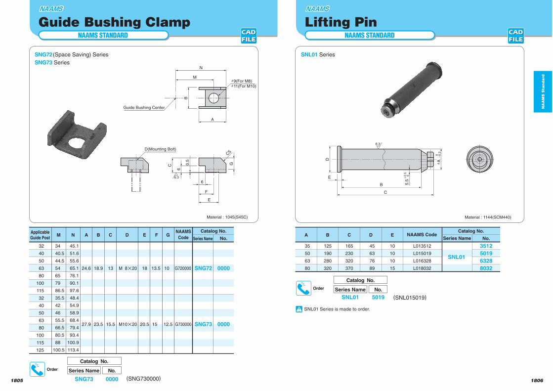
Guide Bushing ClampNAAMS STANDARD
Lifting Pin
SNG72 (Space Saving) Series
SNG73 Series
SNL01 Series
D(Mounting Bolt)
h9(For M8)
h11(For M10)
Guide Bushing Center
G
F
N
M
A
B
C 0.5
E
66
C5
6.3
No.
L013512
L015019
L016328
L018032
3512
5019
6328
8032
Catalog No.
SNL01
45
63
76
89
D
10
10
10
15
E
165
230
320
370
C
125
190
280
320
B
35
50
63
80
ASeries Name
NAAMS Code Series Name No.
G720000
G730000
0000
0000
Catalog No.
SNG72
SNG73
NAAMS
Code
32
40
50
63
80
100
115
32
40
50
63
80
100
115
125
Applicable
Guide Post
M 8p20
M10p20
D
13
15.5
C
18
20.5
E
13.5
15
F
10
12.5
G
18.9
23.5
B
24.6
27.9
A
45.1
51.6
55.6
65.1
76.1
90.1
97.6
48.4
54.9
58.9
68.4
79.4
93.4
100.9
113.4
N
34
40.5
44.5
54
65
79
86.5
35.5
42
46
55.5
66.5
80.5
88
100.5
M
Material : 1045(S45C)
Series Name
Catalog No.
SNG73
No.
0000 (SNG730000)
Order
Series Name
Catalog No.
SNL01
No.
5019 (SNL015019)
Order
B
C
E
D
5.5i
0.5
0
6.3
hA
0
o0.3
Material : 1144(SCM440)
SNL01 Series is made to order.
NA
AM
S S
tan
da
rd
18081807
No.
R412511
R413513
R415017
R416321
2511351350176321
Catalog No.
SNR41
110
130
170
210
L
17
27
42
55
H
22
32
47
60
E
25
30
35
45
F
75
95
135
170
G
25
35
50
63
D
No.
R422513
R423515
R425020
R426325
2513351550206325
Catalog No.
SNR42
130
155
200
250
L
17
27
42
55
H
20
25
30
40
J
22
32
47
60
E
25
30
35
45
F
75
95
135
170
G
25
35
50
63
D
No.
R430001
R430002
00010002
Catalog No.
SNR43
Series NameNAAMS Code
Series NameNAAMS Code
Series NameNAAMS Code
Series Name
Catalog No.
SNR43
No.
0001 (SNR430001)
Order
h1
2.5a
0.3
10
30°
30°
h32a0.3
R3
R6.2
5
5
32
M12p20
J
L
6 6
M12p20
hH
hD
d1
1
hE
h1
1
hH
hD
d1
1
hE
h1
1
L
G
6
F
2
C2
C2
48
G
F
R3
2
5
R27.5
54
Material : 1045(S45C)
SNR41 Series SNR430001
SNR430002SNR42 Series
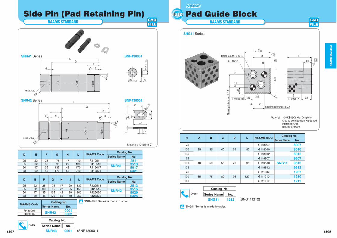
NAAMS STANDARD
Side Pin (Pad Retaining Pin)
SNR41/42 Series is made to order.
NAAMS STANDARD
SNG11 Series
Material : 1045(S45C) with Graphite
Area to be Induction Hardened
(Hatched Area)
HRC40 or more
Pad Guide Block
Series Name
Catalog No.
SNG11
No.
1212 (SNG111212)
Order
No.
G118007
G118010
G118012
G119507
G119510
G119512
G111207
G111210
G111212
8007
8010
8012
9507
9510
9512
1207
1210
1212
Catalog No.
SNG11
80
95
120
L
55
70
95
D
40
55
80
C
35
50
75
B
25
40
65
A
75
100
125
75
100
125
75
100
125
HSeries Name
NAAMS Code
B A
32
Bolt Hole for 2-M16
2-h16G6C6
L
C
10
0 A
0
20
25
L0
o0.03
0o
0.0
3
D
B
H
25
B0.025 A0.025
0.8
0.8
0.8
Spacing tolerance a0.1
Spaci
ng tole
rance
a0
.1
SNG11 Series is made to order.
NA
AM
S S
tan
da
rd
18101809
Series Name
Catalog No.
SNR02
No.
7512 (SNR027512)
Order
No.
R023510
R023512
R023515
R023520
R023522
R023525
R023530
R024010
R024012
R024015
R024020
R024022
R024025
R024030
R025010
R025012
R025015
R025020
R025022
R025025
R025030
R025510
R025512
R025515
R025520
R025522
R025525
R025530
R026510
R026512
R026515
R026520
R026522
R026525
R026530
R027510
R027512
R027515
R027520
R027522
R027525
R027530
3510
35123515352035223525353040104012401540204022402540305010501250155020502250255030551055125515552055225525553065106512651565206522652565307510751275157520752275257530
Catalog No.
SNR02
100
125
150
200
225
250
300
100
125
150
200
225
250
300
100
125
150
200
225
250
300
100
125
150
200
225
250
300
100
125
150
200
225
250
300
100
125
150
200
225
250
300
L
o49.5
62
62
62
62
62
o49.5
62
62
62
62
62
o49.5
62
62
62
62
62
o49.5
62
62
62
62
62
o49.5
62
62
62
62
62
o49.5
62
62
62
62
62
A
o o o o 99.5
112
137
o o o o 99.5
112
137
o o o o 99.5
112
137
o o o o 99.5
112
137
o o o o 99.5
112
137
o o o o 99.5
112
137
B
65
90
115
165
190
215
265
65
90
115
165
190
215
265
65
90
115
165
190
215
265
65
90
115
165
190
215
265
65
90
115
165
190
215
265
65
90
115
165
190
215
265
D
o
o
o
112
137
162
212
o
o
o
112
137
162
212
o
o
o
112
137
162
212
o
o
o
112
137
162
212
o
o
o
112
137
162
212
o
o
o
112
137
162
212
C
74
99
124
174
199
224
274
74
99
124
174
199
224
274
74
99
124
174
199
224
274
74
99
124
174
199
224
274
74
99
124
174
199
224
274
74
99
124
174
199
224
274
E
35
40
50
55
65
75
F
25
25
30
35
45
45
G
50
60
70
80
90
100
H
2
3
4
5
2
3
4
5
2
3
4
5
2
3
4
5
2
3
4
5
2
3
4
5
Series NameNAAMS Code
No. of
Holes
NAAMS STANDARD
SNR01 Series
Keeper Block
16
12
12
18
Ea0.025
6a
0.0
25
2-h12G6
2-h12 2-h14
2-M10pP1.5
2-M10pP1.5
Fa0.025
15
25
A
A
L
1317
0
32
49
27 7
13
0
17
9
A B C E
0
0
A B C
13
D
D
16Bolt Hole for M12
(h13-h20)
2-h12G6
H
G
H
F
13a
0.0
25
50
R0.
8
L
75
R0.
8
0.0
25
A0.025
A0.025
A0.0250
.8
0.8
0.8
0.80
.8
0.8
0.80.8
Bolt Hole for M16
(h18-h26)
A0.025
R0.
8
Tolerance between
dowel holes:a0.1
Tolerance between
dowel holes:a0.02
R0.
8
Graphite
No.
R012507
R012510
R012515
R012520
R013207
R013210
R013215
R013220
R013707
R013710
R013715
R013720
R014810
R014815
R014820
R014825
2507251025152520320732103215322037073710371537204810481548204825
Catalog No.
SNR01
75
100
150
200
75
100
150
200
75
100
150
200
100
150
200
250
o
o
o
63
o
o
o
63
o
o
o
63
o
o
63
83
o o 63
113
o o 63
113
o o 63
113
o 63
113
153
38
63
113
163
38
63
113
163
38
63
113
163
63
113
163
213
51
76
126
176
51
76
126
176
51
76
126
176
76
126
176
226
25
32
37
48
15
15
30
30
37
45
50
60
L A B C D E F H
2
3
4
2
3
4
2
3
4
2
3
4
Series NameNAAMS Code
No. of
Holes
SNR02 Series
Material : 1045(S45C) with Graphite
Area to be Induction Hardened
(Hatched Area)
HRC40 or more
SNR01/02 Series ismade to order.
NA
AM
S S
tan
da
rd
1812
NAAMS STANDARD
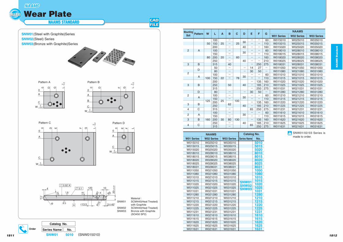
SNW01 (Steel with Graphite)Series
SNW02 (Steel) Series
SNW03 (Bronze with Graphite)Series
1811
Wear Plate
No.
W035010
W035015
W035020
W038010
W038015
W038020
W038025
W038031
W031050
W031080
W031010
W031015
W031020
W031025
W031031
W031280
W031210
W031215
W031220
W031225
W031231
W031610
W031615
W031620
W031625
W031631
W025010
W025015
W025020
W028010
W028015
W028020
W028025
W028031
W021050
W021080
W021010
W021015
W021020
W021025
W021031
W021280
W021210
W021215
W021220
W021225
W021231
W021610
W021615
W021620
W021625
W021631
W015010
W015015
W015020
W018010
W018015
W018020
W018025
W018031
W011050
W011080
W011010
W011015
W011020
W011025
W011031
W011280
W011210
W011215
W011220
W011225
W011231
W011610
W011615
W011620
W011625
W011631
50105015502080108015802080258031105010801010101510201025103112801210121512201225123116101615162016251631
Catalog No.
SNW01SNW02SNW03
NAAMS
W035010
W035015
W035020
W038010
W038015
W038020
W038025
W038031
W031050
W031080
W031010
W031015
W031020
W031025
W031031
W031280
W031210
W031215
W031220
W031225
W031231
W031610
W031615
W031620
W031625
W031631
W025010
W025015
W025020
W028010
W028015
W028020
W028025
W028031
W021050
W021080
W021010
W021015
W021020
W021025
W021031
W021280
W021210
W021215
W021220
W021225
W021231
W021610
W021615
W021620
W021625
W021631
W015010
W015015
W015020
W018010
W018015
W018020
W018025
W018031
W011050
W011080
W011010
W011015
W011020
W011025
W011031
W011280
W011210
W011215
W011220
W011225
W011231
W011610
W011615
W011620
W011625
W011631
50
80
100
125
160
A
B
D
A
B
D
A
B
C
A
B
C
2
3
2
3
2
3
4
2
3
4
W
100
150
200
100
150
200
250
315
50
80
100
150
200
250
315
80
100
150
200
250
315
100
150
200
250
315
L
25
20
22
25
30
A
-------40
----
50
---
62
---80
--
B
25
60
78
100
130
C
30
40
30
40
--
30
40
-
30
40
30
40
D
--------14
30
-----30
----65
---
65
E
- - - - - - -
250
27
50
- -
135
185
250
50
- -
135
185
250
- -
135
185
250
F
60
110
160
60
110
160
210
275
- - 60
110
160
210
275
- 60
110
160
210
275
60
110
160
210
275
GNAAMS
Series NameW03 SeriesW02 SeriesW01 Series
W03 SeriesW02 SeriesW01 Series
Mounting
BoltPattern
Series Name
Catalog No.
SNW01
No.
5010 (SNW015010)
Order
3p45°
20a
0.0
1
30°
10
15°
h13.5
h20
R5
0
W
A
13
0.1
0 D G L
0
B
W
A
0 D F G L
0 0 E F LD E F G L
C
0
W
A
C
0
W
A
C
R
R3
R10
4
C
A0.02
A
6.3
6.3
1.6
Pattern A Pattern B
Pattern DPattern C
0o
0.2
0o
0.2
0o
0.2
0o0.2
0o0.2
0o0.2
0o0.2
SNW01/02/03 Series is
made to order.
Material :
SNW01 SCM440(Heat Treated)
with Graphite
SNW02 SCM440(Heat Treated)
SNW03 Bronze with Graphite
(SO#50 SP2)
1813
NA
AM
S S
tan
da
rd
1814
NAAMS STANDARD
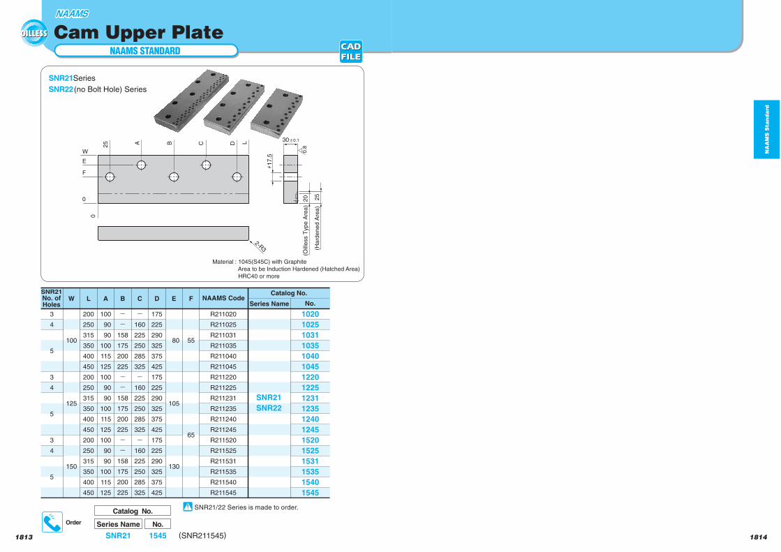
Cam Upper Plate
SNR21Series
SNR22 (no Bolt Hole) Series
E
W
F
0
25 A B C D L
0
2-R3
h1
7.5
25
20
30a0.1
0.8
(Oill
ess T
yp
e A
rea
)
(Ha
rde
ne
d A
rea
)
No.
R211020
R211025
R211031
R211035
R211040
R211045
R211220
R211225
R211231
R211235
R211240
R211245
R211520
R211525
R211531
R211535
R211540
R211545
1020
1025
1031
1035
1040
1045
1220
1225
1231
1235
1240
1245
1520
1525
1531
1535
1540
1545
Catalog No.
SNR21
SNR22
55
65
F
80
105
130
E
175
225
290
325
375
425
175
225
290
325
375
425
175
225
290
325
375
425
D
--
158
175
200
225
--
158
175
200
225
--
158
175
200
225
B
100
90
90
100
115
125
100
90
90
100
115
125
100
90
90
100
115
125
A
200
250
315
350
400
450
200
250
315
350
400
450
200
250
315
350
400
450
L
100
125
150
W
-160
225
250
285
325
-160
225
250
285
325
-160
225
250
285
325
C
3
4
5
3
4
5
3
4
5
SNR21
No. of
Holes Series NameNAAMS Code
Series Name
Catalog No.
SNR21
No.
1545 (SNR211545)
Order
Material : 1045(S45C) with Graphite
Area to be Induction Hardened (Hatched Area)
HRC40 or more
SNR21/22 Series is made to order.
NA
AM
S S
tan
da
rd
1816
NAAMS STANDARD
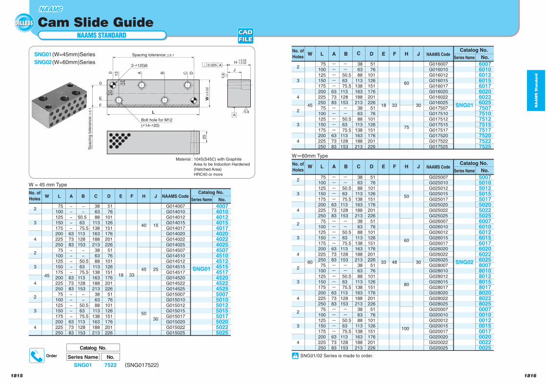
SNG01 (W=45mm)Series
SNG02 (W=60mm)Series
1815
Cam Slide Guide
75
100
125
150
175
200
225
250
75
100
125
150
175
200
225
250
75
100
125
150
175
200
225
250
38
63
88
113
138
163
188
213
38
63
88
113
138
163
188
213
38
63
88
113
138
163
188
213
51
76
101
126
151
176
201
226
51
76
101
126
151
176
201
226
51
76
101
126
151
176
201
226
18 33
40
45
50
15
25
30
−
−
50.5
63
75.5
113
128
153
−
−
50.5
63
75.5
113
128
153
−
−
50.5
63
75.5
113
128
153
−
−
−
−
−
63
73
83
−
−
−
−
−
63
73
83
−
−
−
−
−
63
73
83
HFEDCBAL JSeries Name No.
2
3
4
2
3
4
2
3
4
G014007
G014010
G014012
G014015
G014017
G014020
G014022
G014025
G014507
G014510
G014512
G014515
G014517
G014520
G014522
G014525
G015007
G015010
G015012
G015015
G015017
G015020
G015022
G015025
400740104012401540174020402240254507451045124515451745204522452550075010501250155017502050225025
Catalog No.
SNG01
NAAMS Code
45
WNo. of
Holes
W = 45 mm Type
No.
2
3
4
2
3
4
2
3
4
2
3
4
75
100
125
150
175
200
225
250
75
100
125
150
175
200
225
250
75
100
125
150
175
200
225
250
75
100
125
150
175
200
225
250
38
63
88
113
138
163
188
213
38
63
88
113
138
163
188
213
38
63
88
113
138
163
188
213
38
63
88
113
138
163
188
213
51
76
101
126
151
176
201
226
51
76
101
126
151
176
201
226
51
76
101
126
151
176
201
226
51
76
101
126
151
176
201
226
33 48
50
60
80
100
30
G025007
G025010
G025012
G025015
G025017
G025020
G025022
G025025
G026007
G026010
G026012
G026015
G026017
G026020
G026022
G026025
G028007
G028010
G028012
G028015
G028017
G028020
G028022
G028025
G020007
G020010
G020012
G020015
G020017
G020020
G020022
G020025
5007
5010
5012
5015
5017
5020
5022
5025
6007
6010
6012
6015
6017
6020
6022
6025
8007
8010
8012
8015
8017
80208022802500070010001200150017002000220025
Catalog No.
- - 50.5
63
75.5
113
128
153
- - 50.5
63
75.5
113
128
153
- - 50.5
63
75.5
113
128
153
- - 50.5
63
75.5
113
128
153
-----63
73
83
-----63
73
83
-----63
73
83
-----63
73
83
SNG02
HFE
60
W DCBAL J
No.
2
3
4
2
3
4
75
100
125
150
175
200
225
250
75
100
125
150
175
200
225
250
38
63
88
113
138
163
188
213
38
63
88
113
138
163
188
213
51
76
101
126
151
176
201
226
51
76
101
126
151
176
201
226
18 33
60
75
30
G016007
G016010
G016012
G016015
G016017
G016020
G016022
G016025
G017507
G017510
G017512
G017515
G017517
G017520
G017522
G017525
6007601060126015601760206022602575077510751275157517752075227525
Catalog No.
- - 50.5
63
75.5
113
128
153
- - 50.5
63
75.5
113
128
153
-----63
73
83
-----63
73
83
SNG01
HFE
45
W DCBAL J
No. of
Holes Series Name
Wm60mm Type
NAAMS Code
No. of
Holes Series NameNAAMS Code
Series Name
Catalog No.
SNG01
No.
7522 (SNG017522)
Order
12
12
2-h12G6
Bolt hole for M12
(h14-h20)
13
F
25
J
H
L
0
E
DCBA0
A0.025
0.8
0.8A
i0.05i0.02
Spacing tolerance:a0.1
Sp
acin
g t
ole
ran
ce
:a0.1
Wa
0.0
2
Material : 1045(S45C) with Graphite
Area to be Induction Hardened
(Hatched Area)
HRC40 or more
SNG01/02 Series is made to order.
NA
AM
S S
tan
da
rd
1818
NAAMS STANDARD
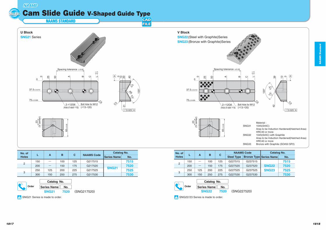
U Block
SNG21 Series
V Block
SNG22 (Steel with Graphite)Series
SNG23 (Bronze with Graphite)Series
1817
Cam Slide Guide V-Shaped Guide Type
Series Name
Catalog No.
SNG21
No.
7520 (SNG217520)
Order Series Name
Catalog No.
SNG22
No.
7520 (SNG227520)
Order
65a
0.0
5
2-h12G6
(Hole of relief h16)
C5
C3
0
12
0°
40
21
20
100L0 CBA50
25
37.5a0.013
75a0.026
Bolt Hole for M12
(h13-h20)A0.025
A
0.8
0.8
R5
Spacing tolerance a0.02
o0.1
o0.3
23
(V c
en
ter)
Bolt Hole for M12
(h13-h20)
L
C5
120°
42
39
13 0C
0
A50
250
37.5a0.013
B
75a0.026
C3
65a
0.0
5
2-h12G6
(Hole of relief h16)
A
A0.025
0.8
0.8
Spacing tolerance a0.02
o0.1
o0.3
23
(V cente
r)
No.
2
3
G217515
G217520
G217525
G217530
7515
7520
7525
7530
Catalog No.
125
175
225
275
ーー
125
150
SNG21
C
100
150
200
250
BA
150
200
250
300
LSeries Name
NAAMS Code No. of
Holes No.
G237515
G237520
G237525
G237530
G227515
G227520
G227525
G227530
7515
7520
7525
7530
Catalog No.
SNG22
SNG23
125
175
225
275
C
100
150
200
250
B
ーー
125
150
A
150
200
250
300
L
2
3
Series Name
NAAMS Code No. of
Holes Steel Type Bronze Type
Material :
SNG31 1045(S45C)
Area to be Induction Hardened(Hatched Area)
HRC40 or more
SNG32 1045(S45C) with Graphite
Area to be Induction Hardened(Hatched Area)
HRC40 or more
SNG33 Bronze with Graphite (SO#50 SP2)
SNG21 Series is made to order. SNG22/23 Series is made to order.
NA
AM
S S
tan
da
rd
18201819
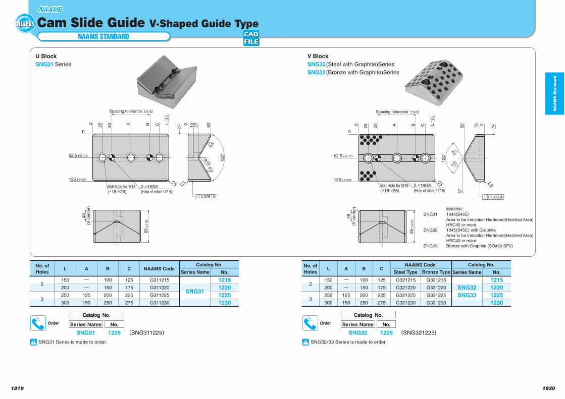
U Block
SNG31 Series
V Block
SNG32 (Steel with Graphite)Series
SNG33 (Bronze with Graphite)Series
A 60
27
15
120°
2-h16G6
(Hole of relief h17.5)
C3C5
0
125a0.026
62.5a0.013
0
LCB50
250
A
A0.025
0.8
0.8
Bolt Hole for M16
(h18-h26)
R10
85a
0.0
5
Spacing tolerance a0.02
o0.1
o0.3
28
(V cente
r)
12
0°
57
52
15 0CBA
2-h16G6
(Hole of relief h17.5)Bolt Hole for M16
(h18-h26)
50
25 L
125a0.026
62.5a0.013
0
0
C5 C3
85a
0.0
5
A
A0.025
0.8
0.8
Spacing tolerance a0.02
o0
.1o
0.3
28
(V c
en
ter)
No.
G331215
G331220
G331225
G331230
G321215
G321220
G321225
G321230
1215
1220
1225
1230
Catalog No.
SNG32
SNG33
125
175
225
275
C
100
150
200
250
B
ーー
125
150
A
150
200
250
300
L
2
3
Series Name
NAAMS Code No. of
Holes Steel Type Bronze TypeNo.
2
3
G311215
G311220
G311225
G311230
1215
1220
1225
1230
Catalog No.
125
175
225
275
ーー
125
150
SNG31
C
100
150
200
250
BA
150
200
250
300
LSeries Name
NAAMS Code No. of
Holes
Series Name
Catalog No.
SNG31
No.
1225 (SNG311225)
Order Series Name
Catalog No.
SNG32
No.
1225 (SNG321225)
Order
NAAMS STANDARD
Cam Slide Guide V-Shaped Guide Type
Material :
SNG31 1045(S45C)
Area to be Induction Hardened(Hatched Area)
HRC40 or more
SNG32 1045(S45C) with Graphite
Area to be Induction Hardened(Hatched Area)
HRC40 or more
SNG33 Bronze with Graphite (SO#50 SP2)
SNG31 Series is made to order. SNG32/33 Series is made to order.
NA
AM
S S
tan
da
rd
18221821
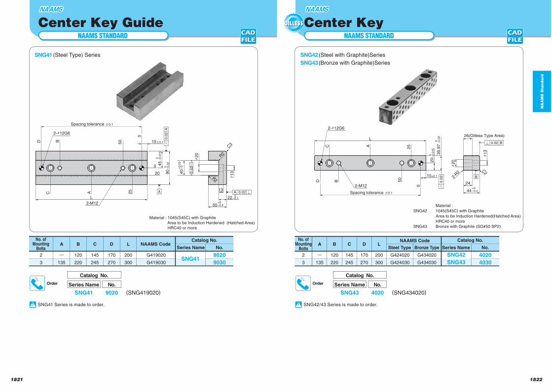
NAAMS STANDARD
Center Key GuideNAAMS STANDARD
Center Key
SNG41 (Steel Type) Series SNG42 (Steel with Graphite)Series
SNG43 (Bronze with Graphite)Series
0-
0.0
15
4
5
13
h2
0A
0.0
2
D B 50
C A
L
25
15a0.1
20
0
0
22
R2
h1
390
0-
0.0
2
40
+0.0
2-
0
50+0-0.4
A0
.02
A 0.02
R2
2-M12
2-h12G6
C3
Spacing tolerance a0.1
0-0.1
No.
2
3
G434020
G434030
G424020
G424030
4020
4030
Catalog No.
SNG42
SNG43
200
300
L
170
270
D
145
245
C
120
220
B
ー135
ASteel Type Bronze Type Series Name
NAAMS Code No. ofMounting
BoltsNo.
2
3
170
270
200
300
G419020
G419030
9020
9030
Catalog No.
145
245
ー135
SNG41
LDC
120
220
BASeries Name
NAAMS Code No. of
MountingBolts
Material : 1045(S45C) with Graphite
Area to be Induction Hardened (Hatched Area)
HRC40 or more
Series Name
Catalog No.
SNG41
No.
9020 (SNG419020)
Order Series Name
Catalog No.
SNG43
No.
4020 (SNG434020)
Order
h2
020
15±0.1
D B
C A
B
L
25
50
0
24
h1
3
44+0-0.4
26(Oilless Type Area)
0.0
2
B0.02
2-M12
2-h12G6
2-R
2
C2
Spacing tolerance a0.1
39
.97
0-
0.0
2
0-
0.0
15
Material :
SNG42 1045(S45C) with Graphite
Area to be Induction Hardened(Hatched Area)
HRC40 or more
SNG43 Bronze with Graphite (SO#50 SP2)
SNG41 Series is made to order. SNG42/43 Series is made to order.
NA
AM
S S
tan
da
rd
18241823
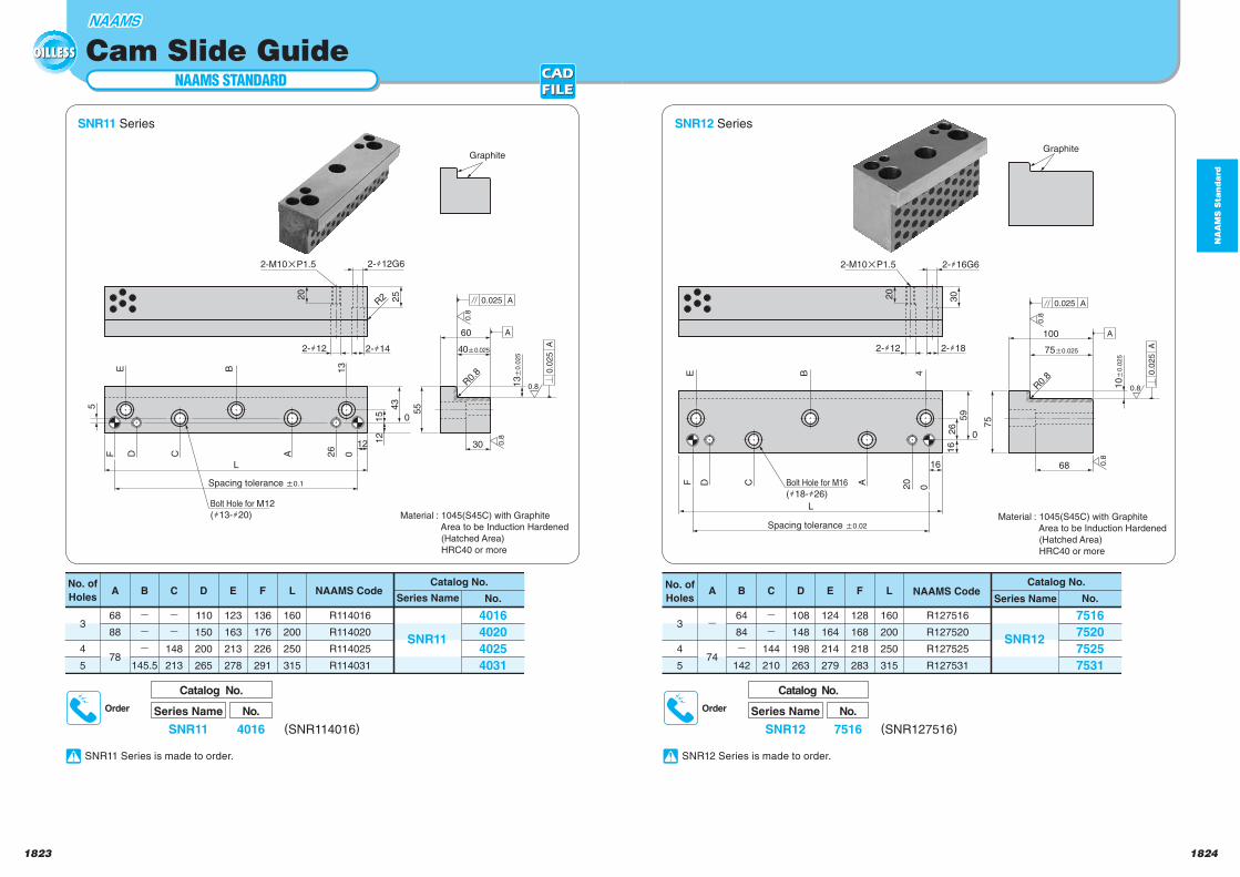
NAAMS STANDARD
Cam Slide Guide
SNR11 Series
Graphite
2-h12G6
R0.
8
13a
0.0
25
0
25
A
30
55
60
2-M10pP1.5
20
E
5
F D C A 26
0
B 13
R2
2-h12 2-h14
L
Bolt Hole for M12
(h13-h20)
12
43
15
A0
.02
5
0.8
0.8
0.8
A0.025
40a0.025
12
Spacing tolerance a0.1
No.
R127516
R127520
R127525
R127531
7516
7520
7525
7531
Catalog No.
SNR12
160
200
250
315
L
128
168
218
283
F
108
148
198
263
D
124
164
214
279
E
--
144
210
C
64
84
-142
B
-
74
A
3
4
5
Series NameNAAMS Code
No. of
HolesNo.
R114016
R114020
R114025
R114031
4016
4020
4025
4031
Catalog No.
SNR11
160
200
250
315
L
136
176
226
291
F
110
150
200
265
D
123
163
213
278
E
--
148
213
C
---
145.5
B
68
88
78
A
3
4
5
Series NameNAAMS Code
No. of
Holes
Material : 1045(S45C) with Graphite
Area to be Induction Hardened
(Hatched Area)
HRC40 or more
Series Name
Catalog No.
SNR11
No.
4016 (SNR114016)
Order Series Name
Catalog No.
SNR12
No.
7516 (SNR127516)
Order
SNR12 Series
Graphite
2-h16G6
2-h18
2-M10pP1.5
30
100
75
26
59
20
0ACDFE B 4
16
20
2-h12
68
0
16
L
R0.
8
10a
0.0
25
A0
.02
5
0.8
0.8
0.8
A0.025
Bolt Hole for M16
(h18-h26)
75a0.025
A
Spacing tolerance a0.02Material : 1045(S45C) with Graphite
Area to be Induction Hardened
(Hatched Area)
HRC40 or more
SNR12 Series is made to order. SNR11 Series is made to order.
NA
AM
S S
tan
da
rd
1826
NAAMS STANDARD
1825
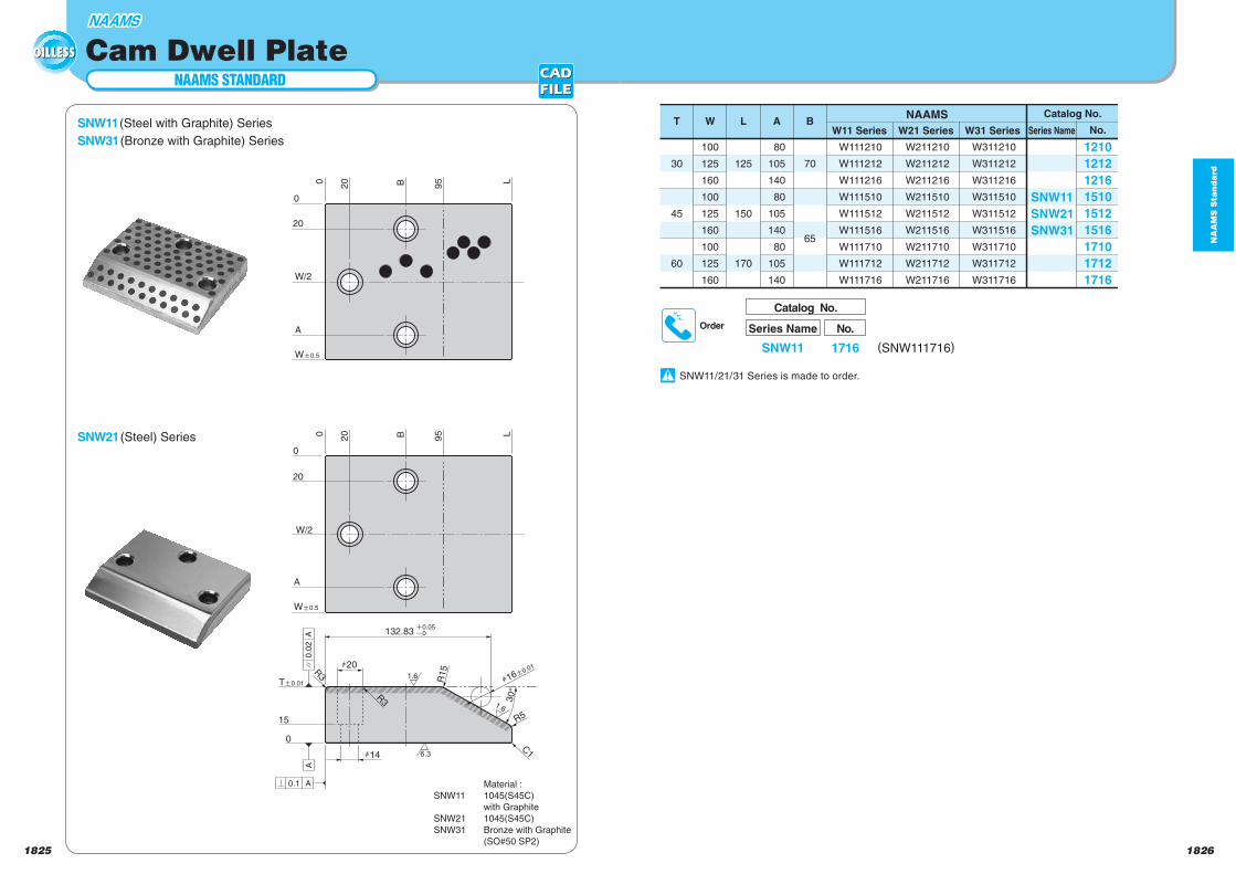
Cam Dwell Plate
Series Name
Catalog No.
SNW11
No.
1716 (SNW111716)
Order
SNW11 (Steel with Graphite) Series
SNW31 (Bronze with Graphite) SeriesNo.
W311210
W311212
W311216
W311510
W311512
W311516
W311710
W311712
W311716
W211210
W211212
W211216
W211510
W211512
W211516
W211710
W211712
W211716
W111210
W111212
W111216
W111510
W111512
W111516
W111710
W111712
W111716
30
45
60
100
125
160
100
125
160
100
125
160
125
150
170
80
105
140
80
105
140
80
105
140
70
65
1210
1212
1216
1510
1512
1516
1710
1712
1716
Catalog No.
SNW11
SNW21
SNW31
NAAMST W L A B
Series NameW31 SeriesW21 SeriesW11 Series
h16a
0.01
Ta0.01
i0.05
o0
h14
h20
0
0
20
95B L
20
A
A
W/2
Wa0.5
Wa0.5
W/2
20
20
95
0
0 LB
A
A0.0
2
R3
15
R15
R5
30°
0
R3
6.3
1.6
1.6
A0.1
C1
132.83
SNW21 (Steel) Series
SNW11/21/31 Series is made to order.
Material :
SNW11 1045(S45C)
with Graphite
SNW21 1045(S45C)
SNW31 Bronze with Graphite
(SO#50 SP2)
European Standard
18281827
Eu
rop
ea
nS
tan
da
rd
VDI DIN Standard
Die Guide Components ……………………………………………………… P.1829 to 1838GP DIN9833 / DIN9825(01) /GPF03(03) /GPF04(04) /GPF05(05)
9834 / VDI-KL
Slide Components ……………………………………………………………… P.1839 to 1844VDI(SP2) /VDI(ST01,ST02) /VSM(SP2,ST)
Cam Slide Components ……………………………………………………… P.1845 to 1858VSOP(SP2,ST) /VG2/2GLF, 3GLF/VPON, VPUN/VPO,VPU/VSOL/VTK
Cam Units (Roller Cam Units) ………………………………………………… P.1859 to 1866PSCX/OCX/DR
AFNOR CNOMO Standard
Die Guide Components ……………………………………………………… P.1867 to 1870ERGP/GPNP/RNG/ERGB/GBNS/GBNH/GBKL
Slide Components ……………………………………………………………… P.1871 to 1876RWPW/RWPF/RWPR/RSP/RSPR/REWP
Cam Slide Components ……………………………………………………… P.1877 to 1886RCUW/RCUS/RHCP/RHCPB/RCSDP/PCSU/PCSV/CSGL
RCSGR/RCSG
European Standard
European Standard
18301829
Eu
rop
ea
nS
tan
da
rd
EUROPEAN STANDARD
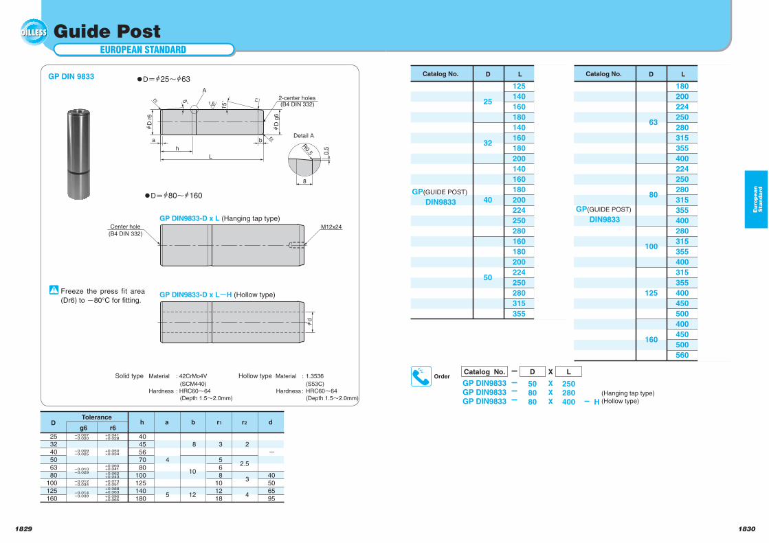
Guide Post
a b
h
L
D r
6
D g
6
15˚ r1
r2
r2 5˚
2-center holes
A
Detail A
0.5
8
R0.5
Center hole M12x24
d
(B4 DIN 332)
(B4 DIN 332)1.6
GP DIN 9833 Catalog No. D L
GP(GUIDE POST)
DIN9833
125
140
160
180
140
160
180
200
140
160
180
200
224
250
280
160
180
200
224
250
280
315
355
25
32
40
50
OrderCatalog No.
GP DIN9833GP DIN9833GP DIN9833
D X LSolid type Material : 42CrMo4V
(SCM440)
Hardness : HRC60 64
(Depth 1.5 2.0mm)
Freeze the press fit area
(Dr6) to 80°C for fitting.
Hollow type Material : 1.3536
(S53C)
Hardness : HRC60 64
(Depth 1.5 2.0mm)
508080
X
X
X
250280400 H
(Hanging tap type)(Hollow type)
DTolerance
r6g6h a b r1 r2 d
253240506380
100125160
4045567080
100125140180
4
5
8
10
12
3
568
101218
2
2.5
3
4
40506595
-0.007-0.020
+0.041+0.028
-0.009-0.025
+0.050+0.034
-0.010-0.029
-0.012-0.034
-0.014-0.039
+0.060+0.041
+0.062+0.043
+0.073+0.051
+0.088+0.063
+0.090+0.065
Catalog No. D L
GP(GUIDE POST)
DIN9833
180
200
224
250
280
315
355
400
224
250
280
315
355
400
280
315
355
400
315
355
400
450
500
400
450
500
560
63
80
100
125
160
D 25 63
D 80 160
GP DIN9833-D x L (Hanging tap type)
GP DIN9833-D x L H (Hollow type)
18321831
Eu
rop
ea
nS
tan
da
rd
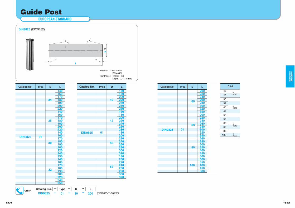
EUROPEAN STANDARD
Guide Post
DIN9825 (ISO9182)
Material : 42CrMo4V
(SCM440)
Hardness : HRC60 64
(Depth 1.0 1.5mm)
Catalog No. Type
DIN9825
L
140160170180190200220140160170180190200220140160170180190200220240250140160170180190200220240250
01
D
24
25
30
32
Catalog No. Type
DIN9825
L
160180200220240250280160180200220240250280180200220240260280300320180200220240260280300320
01
D
40
42
50
52
Catalog No. Type
DIN9825
L
200220240260280300320350200220240260280300320350260280300350400450500300350400450500
01
D
60
63
80
100
3 5
L
hD
h6
8˚
15˚
OrderCatalog No.
DIN9825
Type D
01 30
L
200
24
25
30
32
40
42
50
52
60
63
80
100
0
0.013
0
0.016
0
0.019
0
0.022
(DIN 9825-01-30-200)
18341833
Eu
rop
ea
nS
tan
da
rd
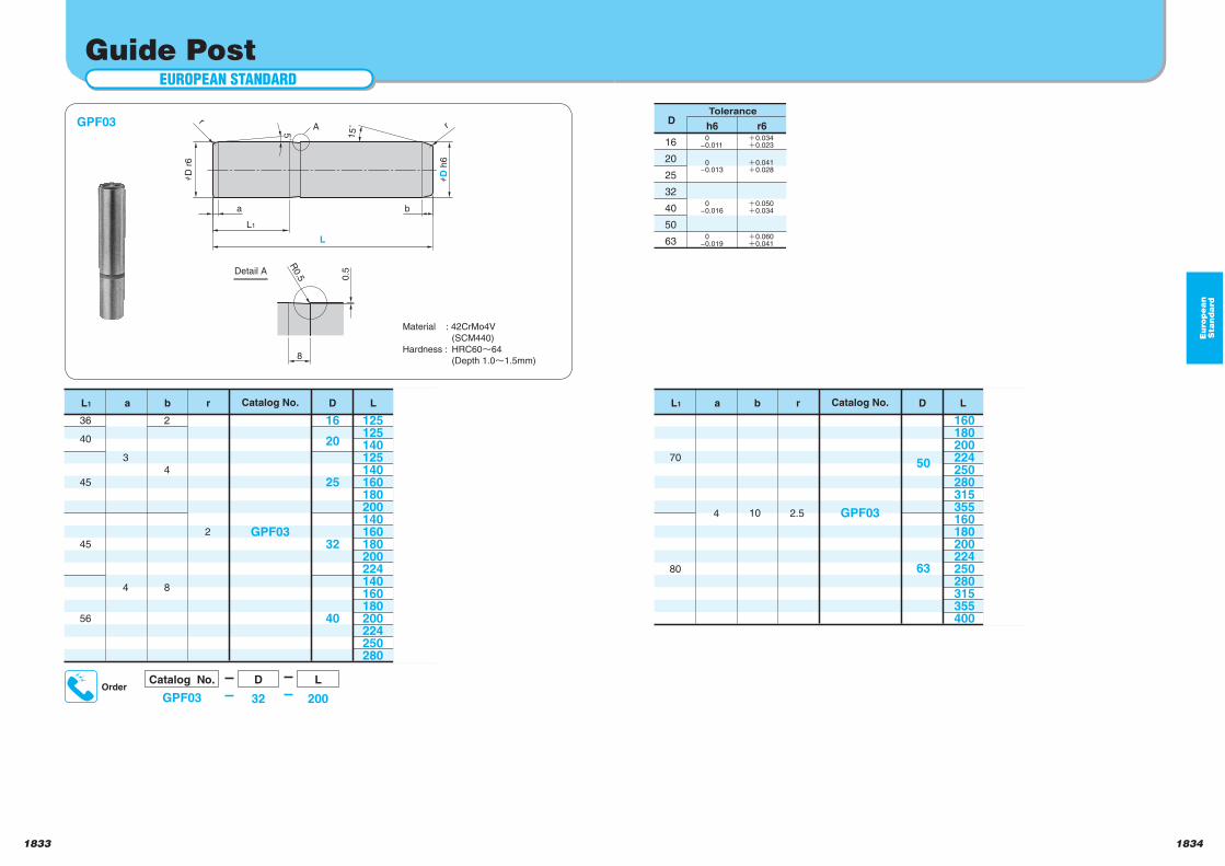
EUROPEAN STANDARD
Guide Post
GPF03
Material : 42CrMo4V
(SCM440)
Hardness : HRC60 64
(Depth 1.0 1.5mm)
Catalog No.
GPF03
L
125125140125140160180200140160180200224140160180200224250280
D
16
20
25
32
40
36
40
45
45
56
3
4
aL1 r
2
b
2
4
8
Catalog No.
GPF03
L
160180200224250280315355160180200224250280315355400
D
50
63
70
80
4
aL1 r
2.5
b
10
15˚
a
A
L1
L
b
hD
r6
hD
h6
r
5˚
rD
Tolerance
h6 r6
16
20
25
32
40
50
63
0
-0.011
0
-0.013
0
-0.016
0
-0.019
0.034
0.023
0.041
0.028
0.050
0.034
0.060
0.041
0.5
8
R0.5
Detail A
OrderCatalog No.
GPF03
D
32
L
200
18361835
Eu
rop
ea
nS
tan
da
rd
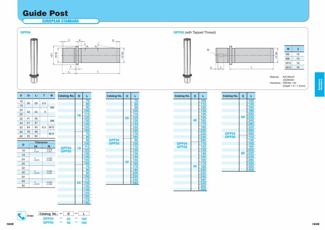
EUROPEAN STANDARD
Guide Post
OrderCatalog No.
GPF04GPF05
D L
3240
160160
GPF04
Material : 42CrMo4V
(SCM440)
Hardness : HRC60 64
(Depth 1.0 1.5mm)
8˚
3
8˚
8
L1 L
hD
f6
hD
1
T
8
hD
h6
M
5 j L
hD
h6
DTolerance
h6 f6
18
19
24
25
32
40
50
63
80
0
0.011
0
0.013
0
0.016
0
0.019
0.016
0.027
0.020
0.033
0.025
0.041
0.030
0.049
D
18
19
24
25
32
40
50
63
80
D1
26
33
41
51
64
76
93
L1
20
24
30
37
45
49
60
T
3.5
5
6.5
M
M6
M8
M10
M12
Catalog No.
GPF04GPF05
L
708090
100110120130140150160708090
100110120130140150160708090
100110120130140150160170180
D
18
19
24
Catalog No.
GPF04GPF05
L
708090
10011012013014015016017018090
100110120130140150160170180200220240280
D
25
32
Catalog No.
GPF04GPF05
L
100110120130140150160170180200220240280110120130140150160170180200220240280320360400
D
40
50
Catalog No.
GPF04GPF05
L
120140160180200220240280320360400120140160180200220240280320360400
D
63
80
GPF05 (with Tapped Thread)
M6
M8
M10
M12
15
15
16
16
18381837
Eu
rop
ea
nS
tan
da
rd
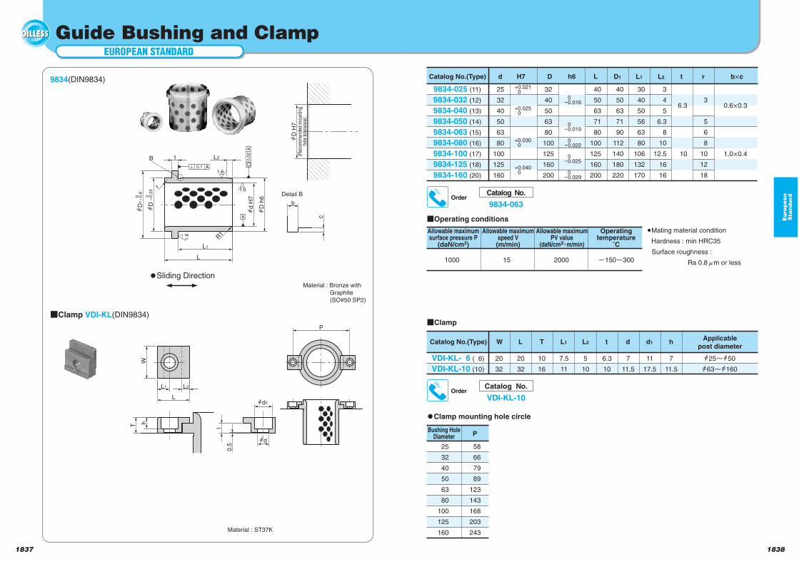
EUROPEAN STANDARD
Guide Bushing and Clamp
B
d
d1
L1
h
b
(Rec
omm
ende
d m
ount
ing
hole
tole
ranc
e)
1.6
L1
Ld
H7
D h
6
D
D1
0-
0.2
5
0-
0.8
A
A0
.02
t
0.1 A
r
R1
1.6
1.6
L2
P
W
L2
L
T
0.5
t
D H
7
Detail B
c
9834(DIN9834)
Material : ST37K
Catalog No.
9834-063Order
Catalog No.(Type) D1 L1 t r b cd
9834-025 (11)
9834-032 (12)
9834-040 (13)
9834-050 (14)
9834-063 (15)
9834-080 (16)
9834-100 (17)
9834-125 (18)
9834-160 (20)
32
40
50
63
80
100
125
160
200
25
32
40
50
63
80
100
125
160
40
50
63
71
80
100
125
160
200
40
50
63
71
90
112
140
180
220
30
40
50
56
63
80
106
132
170
3
4
5
6.3
8
10
12.5
16
16
3
5
6
8
10
12
18
L2
6.3
10
0.6 0.3
1.0 0.4
LDH7 h6
+0.0210
+0.0250
+0.0300
+0.0400 0
-0.029
0-0.025
0-0.022
0-0.019
0-0.016
Material : Bronze with
Graphite
(SO#50 SP2)
Clamp VDI-KL(DIN9834)
Sliding Direction
Operating conditions
1000 15 2000 150 300
Allowable maximumsurface pressure P
(daN/cm2)
Allowable maximumspeed V(m/min)
Allowable maximumPV value
(daN/cm2 m/min)
Operatingtemperature
˚C
Mating material condition
Hardness : min HRC35
Surface roughness :
Ra 0.8 m or less
Clamp
Catalog No.(Type) W L T L1 L2 t d d1 hApplicable
post diameter
VDI-KL- 6 ( 6)
VDI-KL-10 (10)
20
32
20
32
10
16
7.5
11
5
10
6.3
10
7
11.5
11
17.5
7
11.5
25 50
63 160
Catalog No.
VDI-KL-10Order
Clamp mounting hole circle
PBushing Hole
Diameter
25
32
40
50
63
80
100
125
160
58
66
79
89
123
143
168
203
243
Eu
rop
ea
nS
tan
da
rd
18401839
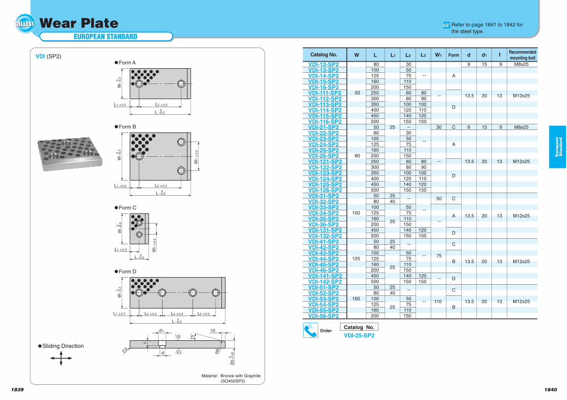
EUROPEAN STANDARD
Wear Plate
L2 0.2
t
0-
0.2
W
0-
0.2
W
0-
0.2
W
0-
0.2
W
0-0.2
L1 0.2
L1 0.2
L2 0.2
L2 0.2
L1 0.2
L1 0.2 L2 0.2L3 0.2
L
0-0.2L
0-0.2L
0-0.2L
W1
0
.2
W1
0.2
15˚
d1
d
10
C3
R5
20
0
-0
.02
1.6
3.2
VDI (SP2)Form A
Form B
Material : Bronze with Graphite
(SO#50SP2)
Catalog No.
VDI-25-SP2Order
Form C
Catalog No. W L L1 L2 W1 Form d d1 tRecommended
mounting bolt
VDI-12-SP2VDI-13-SP2VDI-14-SP2VDI-15-SP2VDI-16-SP2VDI-111-SP2VDI-112-SP2VDI-113-SP2VDI-114-SP2VDI-115-SP2VDI-116-SP2VDI-21-SP2VDI-22-SP2VDI-23-SP2VDI-24-SP2VDI-25-SP2VDI-26-SP2VDI-121-SP2VDI-122-SP2VDI-123-SP2VDI-124-SP2VDI-125-SP2VDI-126-SP2VDI-31-SP2VDI-32-SP2VDI-33-SP2VDI-34-SP2VDI-35-SP2VDI-36-SP2VDI-131-SP2VDI-132-SP2VDI-41-SP2VDI-42-SP2VDI-43-SP2VDI-44-SP2VDI-45-SP2VDI-46-SP2VDI-141-SP2VDI-142-SP2VDI-51-SP2VDI-52-SP2VDI-53-SP2VDI-54-SP2VDI-55-SP2VDI-56-SP2
50
80
100
125
160
801001251602002503003504004505005080
1001251602002503003504004505005080
1001251602004505005080
1001251602004505005080
100125160200
25
2540
25
2540
25
2540
25
305075
1101506080
100120140150
305075
1101506080
100120140150
5075
110150140150
5075
110150140150
5075
110150
L3
8090
100110120150
8090
100110120150
120150
120150
30
50
75
110
A
D
C
A
D
C
A
D
C
B
D
C
B
9
13.5
9
13.5
13.5
13.5
13.5
15
20
15
20
20
20
20
9
13
9
13
13
13
13
M8x25
M12x25
M8x25
M12x25
M12x25
M12x25
M12x25
Form D
Sliding Direction
Refer to page 1841 to 1842 for
the steel type.
18421841
Eu
rop
ea
nS
tan
da
rd
EUROPEAN STANDARD
Wear Plate
15˚
0-
0.2
0-0.2
0-
0.2
0-0.2
W
L1 0.2 L2 0.2
L W
W1
0.2
L1 0.2 L2 0.2
L
W
L1 0.2
L
W1
0.2
0-
0.2
0-0.2
d1
d
10
20
0
-0
.02C
3
R5
t
1.6
3.2
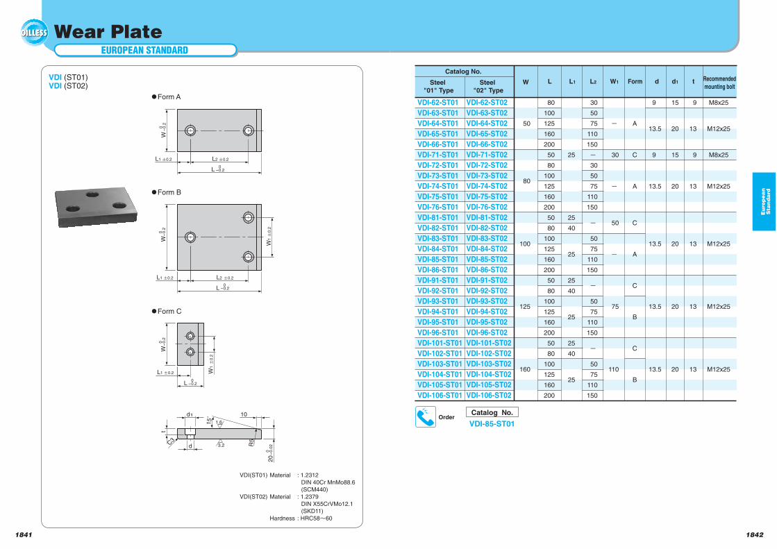
VDI (ST01)VDI (ST02)
Form A
Form B
VDI(ST01) Material : 1.2312
DIN 40Cr MnMo88.6
(SCM440)
VDI(ST02) Material : 1.2379
DIN X55CrVMo12.1
(SKD11)
Hardness : HRC58 60
Catalog No.
VDI-85-ST01Order
Form C
Catalog No.
W L L1 L2 W1 Form d d1 t Recommended
mounting boltSteel
"01" Type
Steel
"02" Type
VDI-62-ST01
VDI-63-ST01
VDI-64-ST01
VDI-65-ST01
VDI-66-ST01
VDI-71-ST01
VDI-72-ST01
VDI-73-ST01
VDI-74-ST01
VDI-75-ST01
VDI-76-ST01
VDI-81-ST01
VDI-82-ST01
VDI-83-ST01
VDI-84-ST01
VDI-85-ST01
VDI-86-ST01
VDI-91-ST01
VDI-92-ST01
VDI-93-ST01
VDI-94-ST01
VDI-95-ST01
VDI-96-ST01
VDI-101-ST01
VDI-102-ST01
VDI-103-ST01
VDI-104-ST01
VDI-105-ST01
VDI-106-ST01
VDI-62-ST02
VDI-63-ST02
VDI-64-ST02
VDI-65-ST02
VDI-66-ST02
VDI-71-ST02
VDI-72-ST02
VDI-73-ST02
VDI-74-ST02
VDI-75-ST02
VDI-76-ST02
VDI-81-ST02
VDI-82-ST02
VDI-83-ST02
VDI-84-ST02
VDI-85-ST02
VDI-86-ST02
VDI-91-ST02
VDI-92-ST02
VDI-93-ST02
VDI-94-ST02
VDI-95-ST02
VDI-96-ST02
VDI-101-ST02
VDI-102-ST02
VDI-103-ST02
VDI-104-ST02
VDI-105-ST02
VDI-106-ST02
50
80
100
125
160
80
100
125
160
200
50
80
100
125
160
200
50
80
100
125
160
200
50
80
100
125
160
200
50
80
100
125
160
200
25
25
40
25
25
40
25
25
40
25
30
50
75
110
150
30
50
75
110
150
50
75
110
150
50
75
110
150
50
75
110
150
30
50
75
110
A
C
A
C
A
C
B
C
B
9
13.5
9
13.5
13.5
13.5
13.5
15
20
15
20
20
20
20
9
13
9
13
13
13
13
M8x25
M12x25
M8x25
M12x25
M12x25
M12x25
M12x25
18441843
Eu
rop
ea
nS
tan
da
rd
EUROPEAN STANDARD
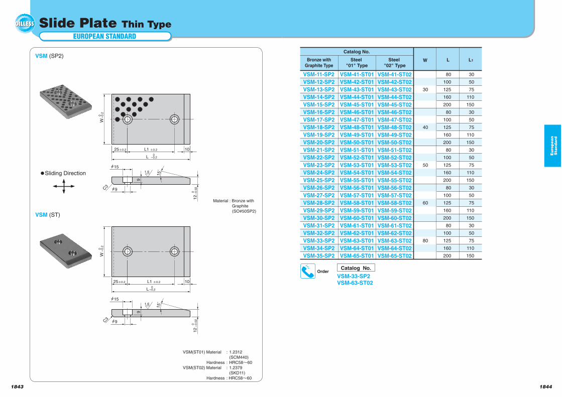
Slide Plate Thin Type
0-
0.0
2
25 0.2
0-
0.0
2
25 0.2
W
L1 0.2
0-
0.2
L 0
-0.215˚
12
10
15
9C3
9
15˚
0-0.2
L1 0.2
L
W
15
9C3
9
0-
0.2
12
10
1.6
1.6
VSM (SP2)
VSM(ST01) Material : 1.2312
(SCM440)
Hardness : HRC58 60
VSM(ST02) Material : 1.2379
(SKD11)
Hardness : HRC58 60
Catalog No.
VSM-33-SP2VSM-63-ST02
Order
80
100
125
160
200
80
100
125
160
200
80
100
125
160
200
80
100
125
160
200
80
100
125
160
200
30
50
75
110
150
30
50
75
110
150
30
50
75
110
150
30
50
75
110
150
30
50
75
110
150
30
40
50
60
80
W L L1
VSM-11-SP2
VSM-12-SP2
VSM-13-SP2
VSM-14-SP2
VSM-15-SP2
VSM-16-SP2
VSM-17-SP2
VSM-18-SP2
VSM-19-SP2
VSM-20-SP2
VSM-21-SP2
VSM-22-SP2
VSM-23-SP2
VSM-24-SP2
VSM-25-SP2
VSM-26-SP2
VSM-27-SP2
VSM-28-SP2
VSM-29-SP2
VSM-30-SP2
VSM-31-SP2
VSM-32-SP2
VSM-33-SP2
VSM-34-SP2
VSM-35-SP2
VSM-41-ST01
VSM-42-ST01
VSM-43-ST01
VSM-44-ST01
VSM-45-ST01
VSM-46-ST01
VSM-47-ST01
VSM-48-ST01
VSM-49-ST01
VSM-50-ST01
VSM-51-ST01
VSM-52-ST01
VSM-53-ST01
VSM-54-ST01
VSM-55-ST01
VSM-56-ST01
VSM-57-ST01
VSM-58-ST01
VSM-59-ST01
VSM-60-ST01
VSM-61-ST01
VSM-62-ST01
VSM-63-ST01
VSM-64-ST01
VSM-65-ST01
VSM-41-ST02
VSM-42-ST02
VSM-43-ST02
VSM-44-ST02
VSM-45-ST02
VSM-46-ST02
VSM-47-ST02
VSM-48-ST02
VSM-49-ST02
VSM-50-ST02
VSM-51-ST02
VSM-52-ST02
VSM-53-ST02
VSM-54-ST02
VSM-55-ST02
VSM-56-ST02
VSM-57-ST02
VSM-58-ST02
VSM-59-ST02
VSM-60-ST02
VSM-61-ST02
VSM-62-ST02
VSM-63-ST02
VSM-64-ST02
VSM-65-ST02
Steel
"02" Type
Steel
"01" Type
Bronze with
Graphite Type
Catalog No.
VSM (ST)
Material : Bronze with
Graphite
(SO#50SP2)
Sliding Direction
18461845
EUROPEAN STANDARD
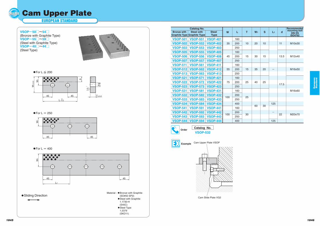
Cam Upper Plate
dT 0.245 45
W1
L 0
-0.2
W0
.2
S
L1
45 45
45 45
W1
W1
1.6
VSOP 50 54(Bronze with Graphite Type)VSOP 55 59(Steel with Graphite Type)VSOP 40 44(Steel Type)
Material : Bronze with Graphite
(SO#50 SP2)
Steel with Graphite
1.1730-H
(S45C)
Steel Type
1.2379
(SKD11)
Catalog No.
VSOP-532Order
10
15
20
25
30
10
15
15
25
25
30
160
200
250
160
200
250
160
200
250
160
200
250
160
200
250
400
160
200
250
400
35
45
55
75
100
100
125
125
11
13.5
17.5
22
M10x30
M12x40
M16x50
M16x60
M20x70
20
30
35
40
60
W L W1 S L1 dT
VSOP-501
VSOP-502
VSOP-503
VSOP-505
VSOP-506
VSOP-507
VSOP-511
VSOP-512
VSOP-513
VSOP-521
VSOP-522
VSOP-523
VSOP-531
VSOP-532
VSOP-533
VSOP-534
VSOP-541
VSOP-542
VSOP-543
VSOP-544
VSOP-551
VSOP-552
VSOP-553
VSOP-555
VSOP-556
VSOP-557
VSOP-561
VSOP-562
VSOP-563
VSOP-571
VSOP-572
VSOP-573
VSOP-581
VSOP-582
VSOP-583
VSOP-584
VSOP-591
VSOP-592
VSOP-593
VSOP-594
VSOP-401
VSOP-402
VSOP-403
VSOP-405
VSOP-406
VSOP-407
VSOP-411
VSOP-412
VSOP-413
VSOP-421
VSOP-422
VSOP-423
VSOP-431
VSOP-432
VSOP-433
VSOP-434
VSOP-441
VSOP-442
VSOP-443
VSOP-444
Steel
Type
Steel with
Graphite Type
Bronze with
Graphite Type
Catalog No. Recommendedmounting bolt
DIN ENISO4762
Sliding Direction
ExampleCam Upper Plate VSOP
Cam Slide Plate VG2
For L 200
For L 250
For L 400
Eu
rop
ea
nS
tan
da
rd
18481847
Eu
rop
ea
nS
tan
da
rd
EUROPEAN STANDARD
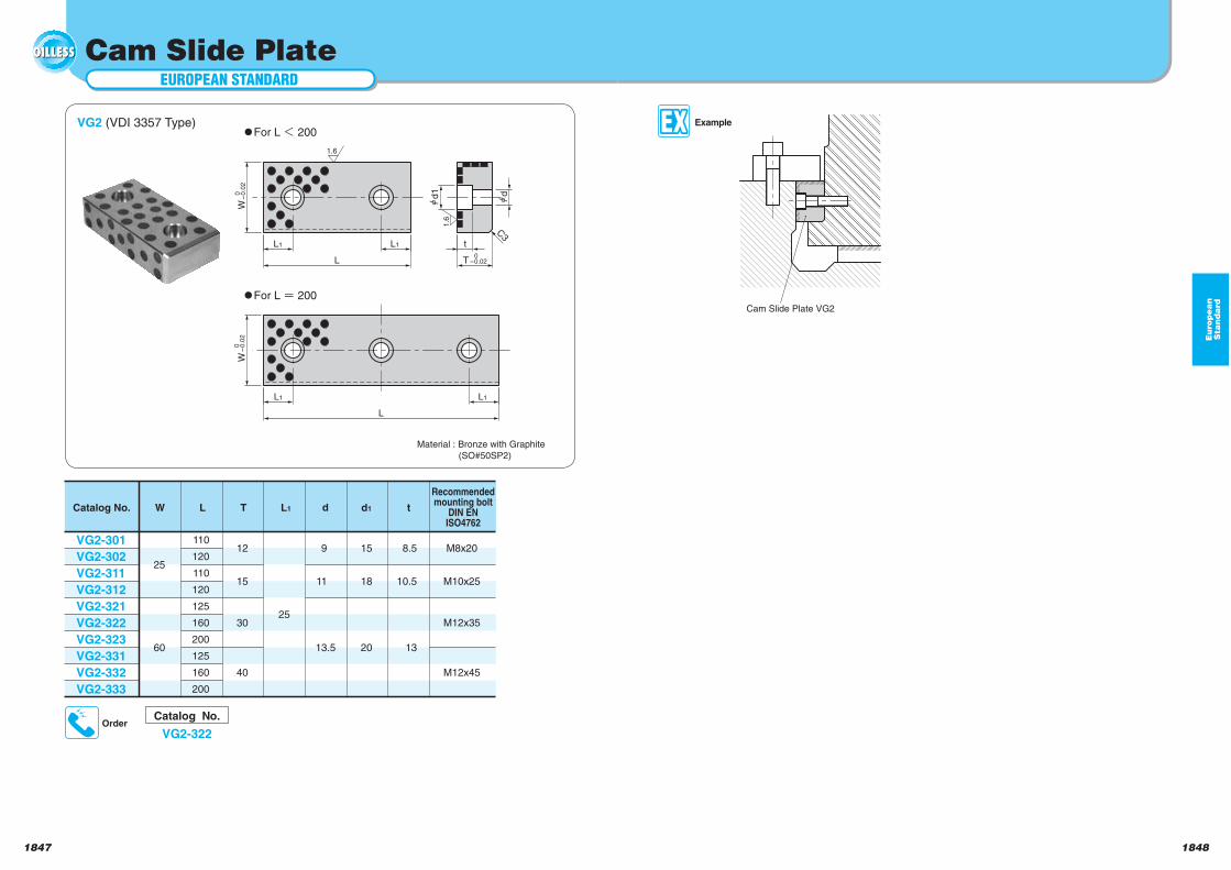
Cam Slide Plate
d1
L1 L1
L
W 0
-0
.02
t
T
d
C3
0-
0.0
2W
L
L1 L1
0-0.02
1.6
1.6
VG2 (VDI 3357 Type)
Material : Bronze with Graphite
(SO#50SP2)
Catalog No.
VG2-322Order
For L 200
For L 200
Example
Cam Slide Plate VG2
Catalog No. d1 t
Recommendedmounting bolt
DIN ENISO4762
W L
VG2-301
VG2-302
VG2-311
VG2-312
VG2-321
VG2-322
VG2-323
VG2-331
VG2-332
VG2-333
25
60
12
15
30
40
110
120
110
120
125
160
200
125
160
200
25
8.5
10.5
13
15
18
20
9
11
13.5
M8x20
M10x25
M12x35
M12x45
dT L1
18501849
Eu
rop
ea
nS
tan
da
rd
EUROPEAN STANDARD
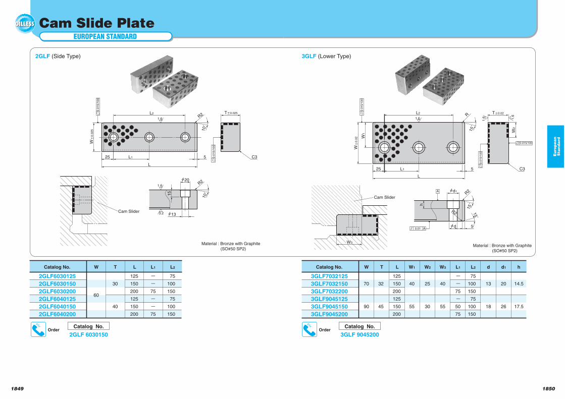
Cam Slide Plate
10˚
Ta0.025
10˚
h20
Wa
0.0
25
25 L1
L2
L
C35
R2
R2
h13
1.6
15
3.2
1.6
0.0
15
/10
0
0.0
15
/10
0Cam Slider
2GLF (Side Type)
Material : Bronze with Graphite
(SO#50 SP2)
Catalog No.
3GLF 9045200Order
Catalog No. W T
3GLF7032125
3GLF7032150
3GLF7032200
3GLF9045125
3GLF9045150
3GLF9045200
70
90
40
55
32
45
25
30
W1
125
150
200
125
150
200
L W2
40
55
W3
-
-
75
-
50
75
L1
75
100
150
75
100
150
L2
13
18
d
20
26
d1
14.5
17.5
h
Catalog No.
2GLF 6030150Order
3GLF (Lower Type)
h
d 5
15˚
15˚
d1
15˚
25 L1
L2
L
W1
Wa
0.0
2
Ta0.02
5
R
C3
R2
R2
0.0
15/1
00
0.0
15/1
00
0.015/100
A
0.01 A
1.6
1.6 1.6
W2
W3
Cam Slider
Material : Bronze with Graphite
(SO#50 SP2)
Catalog No. W T
2GLF6030125
2GLF6030150
2GLF6030200
2GLF6040125
2GLF6040150
2GLF6040200
60
-
-
75
-
-
75
30
40
75
100
150
75
100
150
L1
125
150
200
125
150
200
L L2
1851 1852
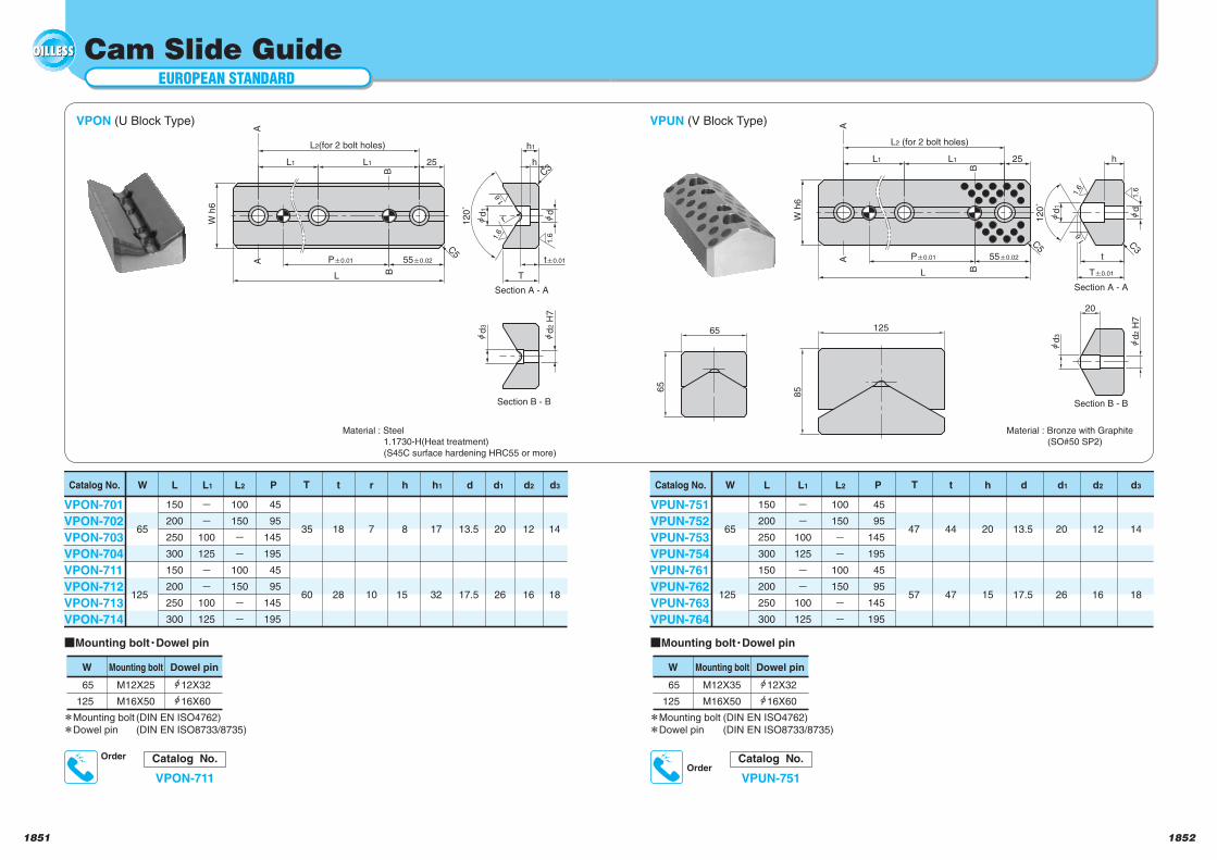
EUROPEAN STANDARD
Cam Slide Guide
h1
C3
d1
25L1L1
L2(for 2 bolt holes)
W h
6
55 0.02P 0.01
L
12
0˚
d
h
t 0.01
T
d2 H
7
d3
AA
BB
Section A - A
Section B - B
C5
65
65
r
1.6
1.6
1.6
VPON (U Block Type)
Catalog No. t r h1 d d1 d3W L
VPON-701
VPON-702
VPON-703
VPON-704
VPON-711
VPON-712
VPON-713
VPON-714
65
125
100
150
o
o
100
150
o
o
150
200
250
300
150
200
250
300
45
95
145
195
45
95
145
195
7
10
h
8
15
17
32
13.5
17.5
20
26
14
18
d2
12
16
18
28
35
60
TL2
o
o
100
125
o
o
100
125
L1 P
VPUN (V Block Type)
Material : Steel
1.1730-H(Heat treatment)
(S45C surface hardening HRC55 or more)
h
d1
25L1L1
L2 (for 2 bolt holes)
55 0.02P 0.01
L
W h
6
12
0˚
d
t
T 0.01
C3
d2 H
7
d3
20
AA
BB
Section A - A
Section B - B
C5
85
125
1.61.6
1.6
Material : Bronze with Graphite
(SO#50 SP2)
W
65
125
Mounting bolt (DIN EN ISO4762)Dowel pin (DIN EN ISO8733/8735)
Mounting bolt
M12X25
M16X50
Dowel pin
12X32
16X60
Mounting bolt Dowel pin
Catalog No.
VPON-711
Order
Catalog No. t h d1 d2 d3W L
VPUN-751
VPUN-752
VPUN-753
VPUN-754
VPUN-761
VPUN-762
VPUN-763
VPUN-764
65
125
100
150
o
o
100
150
o
o
150
200
250
300
150
200
250
300
45
95
145
195
45
95
145
195
20
15
d
13.5
17.5
20
26
12
16
14
18
44
47
47
57
TL2
o
o
100
125
o
o
100
125
L1 P
W
65
125
Mounting bolt (DIN EN ISO4762)
Dowel pin (DIN EN ISO8733/8735)
Mounting bolt
M12X35
M16X50
Dowel pin
12X32
16X60
Mounting bolt Dowel pin
Catalog No.
VPUN-751Order
18541853
Eu
rop
ea
nS
tan
da
rd
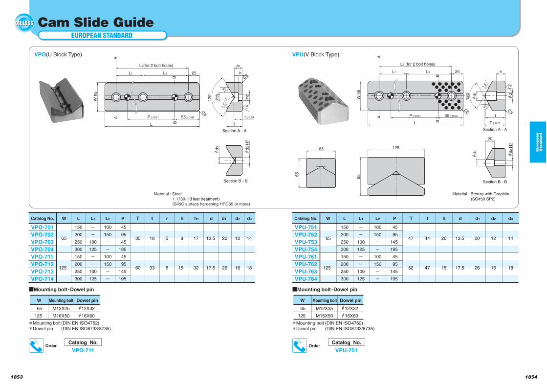
EUROPEAN STANDARD
Cam Slide Guide
h1
C3
d1
25L1L1
L2(for 2 bolt holes)
W h
6
55 0.02P 0.01
L
12
0˚
d
h
t 0.01
T
d2 H
7
d3
AA
BB
Section A - A
Section B - B
C5
65
65
r
1.6
1.6
1.6
VPO(U Block Type)
Catalog No. t r h1 d d1 d3W L
VPO-701
VPO-702
VPO-703
VPO-704
VPO-711
VPO-712
VPO-713
VPO-714
65
125
100
150
100
150
150
200
250
300
150
200
250
300
45
95
145
195
45
95
145
195
5
5
h
8
15
17
32
13.5
17.5
20
26
14
18
d2
12
16
18
33
35
60
TL2
100
125
100
125
L1 P
VPU(V Block Type)
Material : Steel
1.1730-H(Heat treatment)
(S45C surface hardening HRC55 or more)
h
d1
25L1L1
L2 (for 2 bolt holes)
55 0.02P 0.01
L
W h
6
12
0˚
d
t
T 0.01
C3
d2 H
7
d3
20
AA
BB
Section A - A
Section B - B
C5
85
125
1.61.6
1.6
Material : Bronze with Graphite
(SO#50 SP2)
W
65
125
Mounting bolt (DIN EN ISO4762)Dowel pin (DIN EN ISO8733/8735)
Mounting bolt
M12X25
M16X50
Dowel pin
12X32
16X60
Mounting bolt Dowel pin
Catalog No.
VPO-711Order
Catalog No. t h d1 d2 d3W L
VPU-751
VPU-752
VPU-753
VPU-754
VPU-761
VPU-762
VPU-763
VPU-764
65
125
100
150
100
150
150
200
250
300
150
200
250
300
45
95
145
195
45
95
145
195
20
15
d
13.5
17.5
20
26
12
16
14
18
44
47
47
52
TL2
100
125
100
125
L1 P
W
65
125
Mounting bolt (DIN EN ISO4762)
Dowel pin (DIN EN ISO8733/8735)
Mounting bolt
M12X35
M16X50
Dowel pin
12X32
16X60
Mounting bolt Dowel pin
Catalog No.
VPU-751Order
18561855
Eu
rop
ea
nS
tan
da
rd
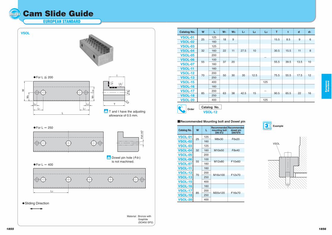
EUROPEAN STANDARD
Cam Slide Guide
d
L1
L2
L1
L2
L
W2
W
T
t
W1
C3
d1
H7
L3
1.6
1.6
0 0.0
2
VSOL
Catalog No.
VSOL-12Order
Catalog No. L2 L3 T t d d1W L
VSOL-01
VSOL-02
VSOL-03
VSOL-04
VSOL-05
VSOL-06
VSOL-07
VSOL-11
VSOL-12
VSOL-13
VSOL-15
VSOL-16
VSOL-17
VSOL-18
VSOL-20
25
32
55
70
85
18
22
37
50
63
125
160
125
160
200
100
160
160
200
250
400
160
200
250
400
9
11
20
30
38
125
125
15.5
30.5
55.5
75.5
90.5
8.5
15.5
39.5
55.5
65.5
9
11
13.5
17.5
22
6
8
10
12
16
10
12.5
15
27.5
35
42.5
L1W1 W2
Material : Bronze with
Graphite
(SO#50 SP2)
Sliding Direction
For L 200
For L 250
For L 400
T and t have the adjusting
allowance of 0.5 mm.
Dowel pin hole ( d1)
is not machined.
Example
VSOL
Catalog No.Recommendedmounting bolt
DIN 912W L
VSOL-01
VSOL-02
VSOL-03
VSOL-04
VSOL-05
VSOL-06
VSOL-07
VSOL-11
VSOL-12
VSOL-13
VSOL-15
VSOL-16
VSOL-17
VSOL-18
VSOL-20
25
32
55
70
85
125
160
125
160
200
100
160
160
200
250
400
160
200
250
400
M8x30
M10x50
M12x80
M16x100
M20x120
Recommendeddowel pinDIN7979
6x20
8x40
10x60
12x70
16x70
Recommended Mounting bolt and Dowel pin
18581857
Eu
rop
ea
nS
tan
da
rd
EUROPEAN STANDARD
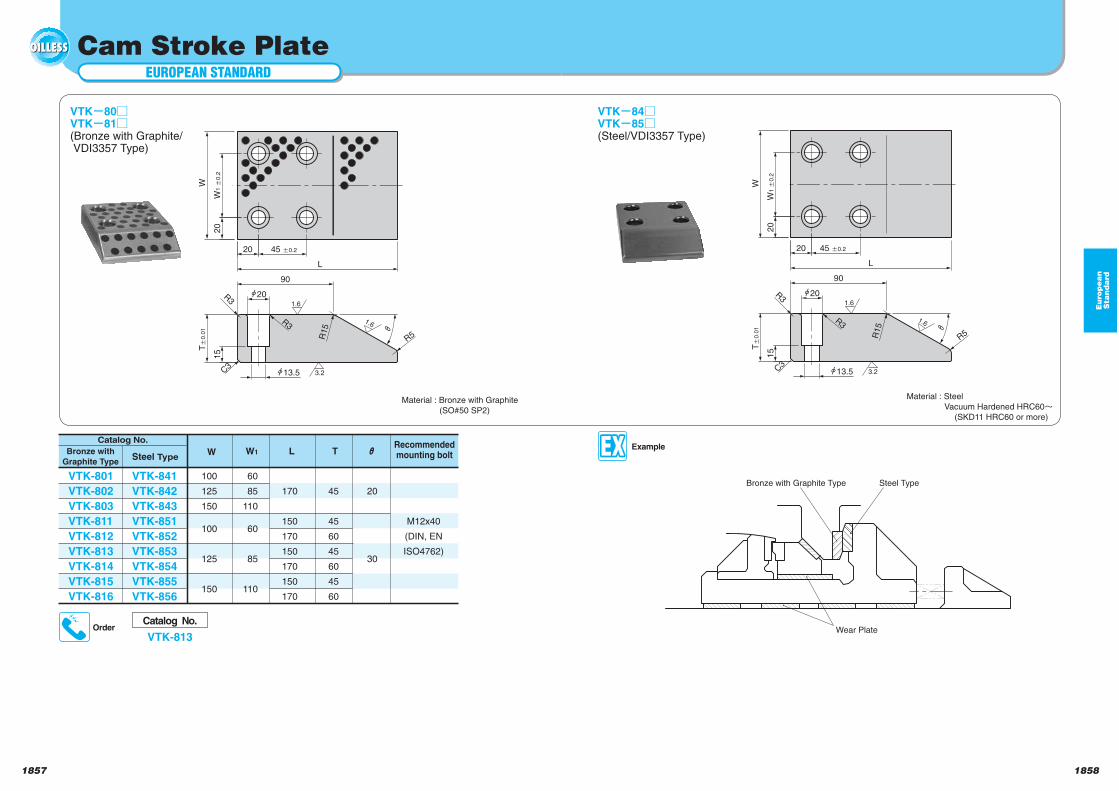
Cam Stroke Plate
VTK 80VTK 81(Bronze with Graphite/ VDI3357 Type)
Material : Bronze with Graphite
(SO#50 SP2)
20
30
170
150
170
150
170
150
170
60
85
110
60
85
110
100
125
150
100
125
150
M12x40
(DIN, EN
ISO4762)
45
45
60
45
60
45
60
W W1 TL
VTK-801
VTK-802
VTK-803
VTK-811
VTK-812
VTK-813
VTK-814
VTK-815
VTK-816
VTK-841
VTK-842
VTK-843
VTK-851
VTK-852
VTK-853
VTK-854
VTK-855
VTK-856
Steel TypeBronze with
Graphite Type
Catalog No.Recommendedmounting bolt
Catalog No.
VTK-813Order
15
20
20
20
L
45 0.2
W1
0.2
W
90
13.5
R3
R5
C3
R3R
15
T0
.01
1.6
1.6
3.2
15
20
R3
13.5
90
L
45 0.220
C3
R3
W
W1
0.2
20
R5R15
T0
.01
1.6
1.6
3.2
Material : Steel
Vacuum Hardened HRC60
(SKD11 HRC60 or more)
VTK 84VTK 85(Steel/VDI3357 Type)
Example
Wear Plate
Steel TypeBronze with Graphite Type
1859 1860
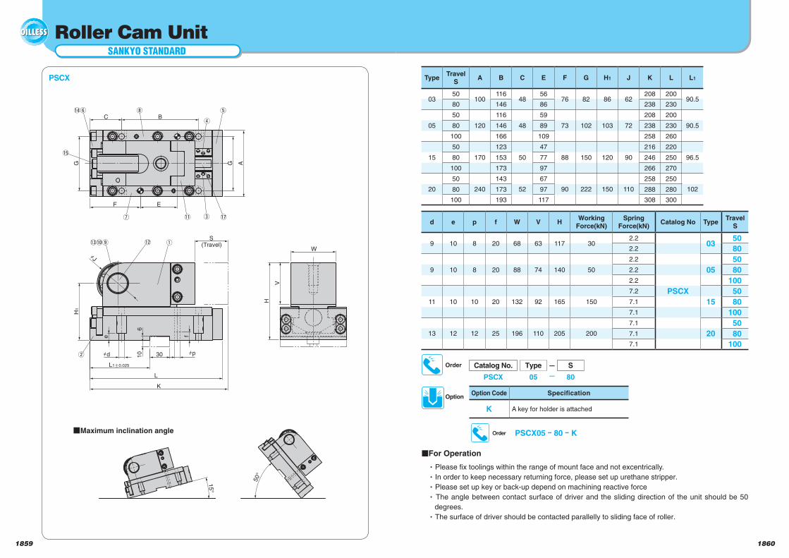
PSCX05 ー 80 ー KOrder
Option Code Specification
K A key for holder is attached
Option
Catalog No. Type – S
PSCX 05 80
Order
Roller Cam Unit
L
H1
30
AG
B
E
V
hJ
S(Travel)
C
F
W
K
H
e
G
hd hp
f
610
!1 !7
!2 q
!5
!3!0o
u
w
r
ti!4y
L1a0.025
e
50°
15°
qMaximum inclination angle
TypeTravel
SA B C E F G H1 J K L L1
0350
100116
4856
76 82 86 62208 200
90.580 146 86 238 230
05
50
120
116
48
59
73 102 103 72
208 200
90.580 146 89 238 230
100 166 109 258 260
15
50
170
123
50
47
88 150 120 90
216 220
96.580 153 77 246 250
100 173 97 266 270
20
50
240
143
52
67
90 222 150 110
258 250
10280 173 97 288 280
100 193 117 308 300
d e p f W V HWorking
Force(kN)
Spring
Force(kN)Catalog No Type
Travel
S
9 10 8 20 68 63 117 302.2
PSCX
0350
2.2 80
9 10 8 20 88 74 140 50
2.2
05
50
2.2 80
2.2 100
11 10 10 20 132 92 165 150
7.2
15
50
7.1 80
7.1 100
13 12 12 25 196 110 205 200
7.1
20
50
7.1 80
7.1 100
For Operation
Please fix toolings within the range of mount face and not excentrically.
In order to keep necessary returning force, please set up urethane stripper.
Please set up key or back-up depend on machining reactive force
The angle between contact surface of driver and the sliding direction of the unit should be 50
degrees.
The surface of driver should be contacted parallelly to sliding face of roller.
SANKYO STANDARD
PSCX
1861 1862
Roller Cam Unit
Spring Specification
TypeTravel
SModel Remark
0350 M2-150-50
Gas spring by KALLER
80 M2-150-80
05
50 M2-150-50
80 M2-150-80
100 M2-150-100
15
50 X500-50
80 X500-80
100 X500-100
20
50 X750-50
80 X750-80
100 X750-100
Table of Components
No. Descripsion Qty Material and Remark
Cam Slider 1 S45C(1045)
Base 1 S45C(1045)
Cam Slide Guide-L 1 Bronze with Graphite(SO#50SP7)
Cam Slide Guide-R 1 Bronze with Graphite(SO#50SP7)
Front Plate 1 S45C(1045)
Stopper Plate 1 S45C(1045)
Upper Plate-L 1 Bronze with Graphite(SO#50SP7)
Upper Plate-R 1 Bronze with Graphite(SO#50SP7)
Roller 1 SUJ-2
Bush 1 Bronze with Graphite(SO#50SP2)
Mount Face Plate 1 S45C(1045)
Pin 1 S45C(1045)
Washer 2 Bronze with Graphite(SO#50SP2)
Urethane 2 Urethane
Spring Stopper 1 SS400(1020)
Spacer 1 SS400(1020)
Gas Spring 1 Refer to Spring Specification
SANKYO STANDARD
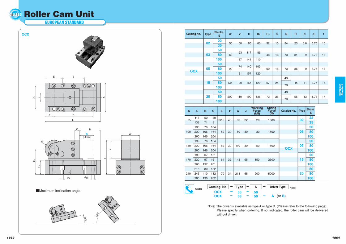
18641863
EUROPEAN STANDARD
Roller Cam Unit
15ϒ
(Stroke)
K
L
A
F C
JG
E B
d d1
H2
H1
R
S W
V
H
t
N
50ϒ
OCX Catalog No. Type
OCX
Stroke
S
22
35
50
80
100
50
80
100
50
80
100
50
80
100
W
50
63
90
135
200
V
50
63
87
74
91
90
110
H
85
117
141
140
157
165
190
H1
63
86
110
103
120
120
135
H2
32
48
60
67
72
K
15
16
16
25
25
N
34
73
73
43
73
43
73
R
23
31
36
45
55
d
6.6
9
9
11
13
d1
5.75
7.75
7.75
9.75
11.75
t
10
15
18
14
17
02
03
05
15
20
Maximum inclination angle
Eu
rop
ea
nS
tan
da
rd
OrderCatalog No.
OCXOCX
Type S
0303
5050
Driver Type
A (or B)
Catalog No. Type
OCX
Stroke
S
SpringForce
(N)
WorkingForce (kN)
JGFECBLA
22
35
50
80
100
50
80
100
50
80
100
50
80
100
1000
1500
1500
2500
5000
20
30
50
150
200
22
30
30
65
65
63
80
110
148
218
43
30
30
32
34
32.5
59
59
64
70
30
51
134
164
204
134
164
204
131
161
201
152
182
202
50
71
76
106
146
76
106
146
67
97
137
80
110
130
115
136
190
220
260
190
220
260
190
220
260
215
245
265
75
100
130
170
240
02
03
05
15
20
Note)
Note) The driver is available as type A or type B. (Please refer to the following page)
Please specify when ordering. If not indicated, the roller cam will be delivered
without driver.
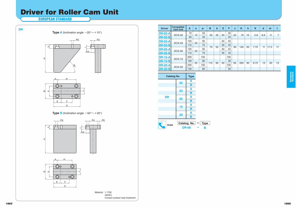
18661865
Eu
rop
ea
nS
tan
da
rd
EUROPEAN STANDARD
Driver for Roller Cam Unit
h
J
a a1
E
A
B b
F
50˚
H
h
K
A
a1a
E
B b
F
d
d1
t
d
J
Kd
t
d1
H
DR DriverCompatibleCam Unit
DR-02-A
DR-02-B
DR-03-A
DR-03-B
DR-05-A
DR-05-B
DR-15-A
DR-15-B
DR-20-A
DR-20-B
A
OCX-02
OCX-03
OCX-05
OCX-15
OCX-20
70
60
135
115
135
115
200
130
200
130
a
10
20
20
25
a1
50
40
95
75
95
75
150
80
150
80
B
50
75
115
b
35
52
90
E
20
40
35
40
35
50
F
30
20
55
45
55
45
100
30
100
30
J
22
30
65
H
70
140
205
h
10
20
30
K
5.8
7.75
9.75
d
6.6
11
13
d1
11
17.5
20
t
7
11
13
Material : 1.1730
(S45C)
Contact surface heat treatment
Type B (Inclination angle 50° 20°)
Catalog No.
DR
Type
A
B
A
B
A
B
A
B
A
B
02
03
05
15
20
Type A (Inclination angle 20° 15°)
OrderCatalog No.
DR-05
Type
B
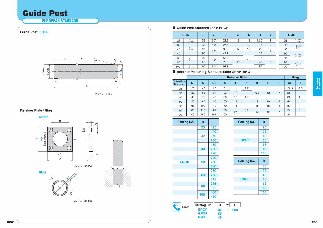
18681867
Eu
rop
ea
nS
tan
da
rd
EUROPEAN STANDARD
Guide Post
(Pos
t dia
met
er)
d1
15ϒ
r
R
D h
5
D1
D h
5
D d
8
a b
L1 e
L
D1
d
A
A
B
B
D
D1
d
t
T
h
D(P
ost d
iamete
r)
Guide Post ERGP
Material : S45C
Guide PostDiameter
Retainer Plate Ring
25
32
40
50
63
80
100
25
32
40
50
63
80
100
25
32
40
50
63
80
100
Catalog No.
ERGP
L
125
140
160
200
180
200
220
220
250
280
250
280
315
315
355
400
450
25
32
40
50
63
80
100
25
32
63
80
100
125
160
2.7
4.2
4.2
6.2
6.2
22.3
27.8
35.8
45.8
56.8
73.8
93.8
8
12
18
8
10
12
16
12.5
16
20
25
31.5
40
50
2
2
3
5
45
56
70
80
100
110
140
D
D
D h5 L1 e D1 a b R r D d8
A
28
37
45
55
70
87
107
D1
31
36
50
55
70
80
100
B
10
12
14
18
20
T
2.7
4.2
6.2
h
6.6
9
11
14
d
12
16
18
22
d1
7
9
11
13
t
22.5
28
36
46
57
74
94
D1
2.5
4
6
d
25
32
40
50
63
80
100
Catalog No.
GPNP
25
32
40
50
63
80
100
D
Catalog No.
RNG
25
32
40
50
63
80
100
D
0
-0.009
0
-0.009
0
-0.013
0
-0.015
-0.065
-0.098
-0.080
-0.119
-0.100
-0.146
-0.120
-0.174
Retainer Plate / Ring
Material : SS400
Material : SS400
RNG
GPNP
OrderCatalog No.
ERGPGPNPRNG
D L
325040
200
Guide Post Standard Table ERGP
Retainer Plate/Ring Standard Table GPNP RNG
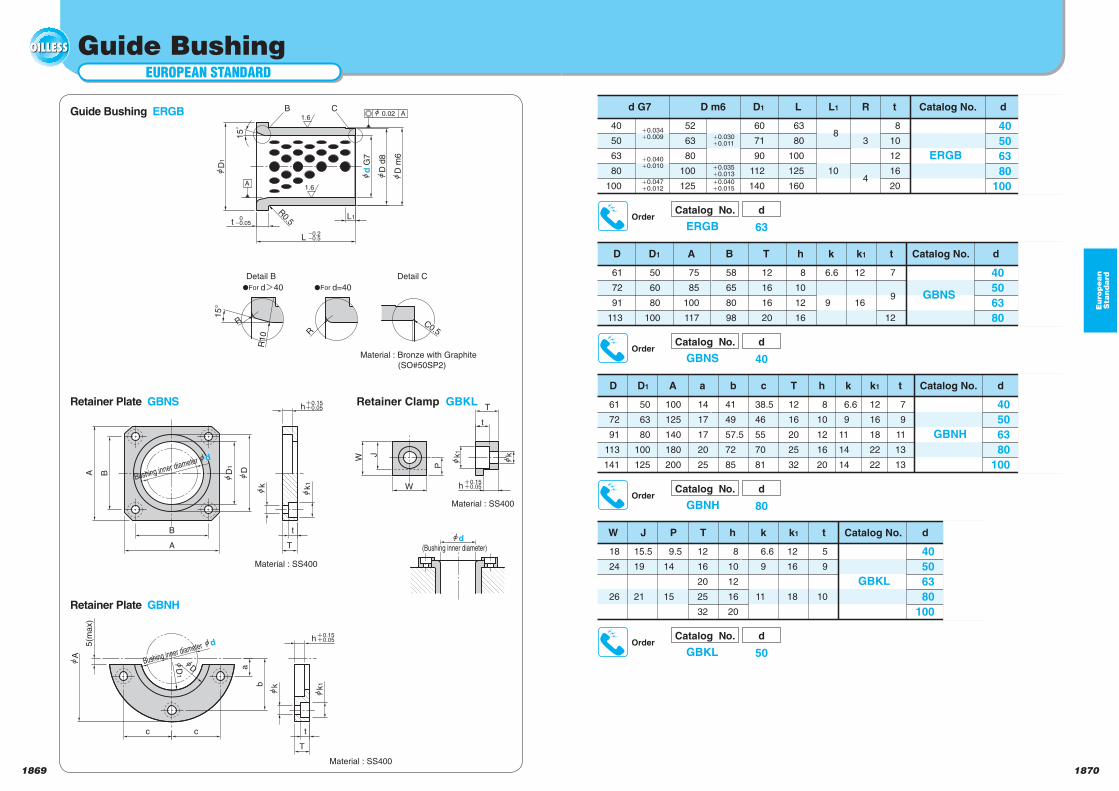
18701869
Eu
rop
ea
nS
tan
da
rd
EUROPEAN STANDARD
Guide Bushing
15°
15
˚
0o0.05
tFor d=40
Detail C
R
tFor dd40
R
Detail B
R10
L
hD
1
o0.2o0.5
t
A
R0.5
1.6
B
1.6
h G
7
hD
d8
hD
m6
L1
h 0.02C
A
C0.5
Guide Bushing ERGB
Material : Bronze with Graphite
(SO#50SP2)
k
h 0.150.05
T
T
Bushing inner diameter d
A
B
A B DD1
h
k k1
t
DD1
a
b
5(m
ax)
c c t
h
k k1
W J
W
P
t
T
k1
0.150.05
0.150.05
A
d(Bushing inner diameter)
Bushing inner diameter d
Catalog No.
ERGB
40
50
63
80
100
d
3
4
R
8
10
L1
63
80
100
125
160
L
8
10
12
16
20
t
60
71
90
112
140
D1
52
63
80
100
125
D m6
40
50
63
80
100
d G7
i0.034
i0.009
i0.040
i0.010
i0.047
i0.012
i0.030
i0.011
i0.035
i0.013
i0.040
i0.015
Catalog No.
GBNS
40
50
63
80
d
12
16
k1
7
9
12
t
6.6
9
k
8
10
12
16
h
12
16
16
20
T
75
85
100
117
A
58
65
80
98
B
50
60
80
100
D1
61
72
91
113
D
Catalog No.
GBNH
40
50
63
80
100
d
6.6
9
11
14
14
k
12
16
18
22
22
k1
7
9
11
13
13
t
8
10
12
16
20
h
12
16
20
25
32
T
38.5
46
55
70
81
c
100
125
140
180
200
A
14
17
17
20
25
a
41
49
57.5
72
85
b
50
63
80
100
125
D1
61
72
91
113
141
D
Catalog No.
GBKL
40
50
63
80
100
d
5
9
10
t
12
16
18
k1
12
16
20
25
32
T
8
10
12
16
20
h
6.6
9
11
k
9.5
14
15
P
18
24
26
W
15.5
19
21
J
Retainer Plate GBNS
Retainer Plate GBNH
Retainer Clamp GBKL
Material : SS400
Material : SS400
Material : SS400
OrderCatalog No.
ERGB
d
63
OrderCatalog No.
GBNS
d
40
OrderCatalog No.
GBNH
d
80
OrderCatalog No.
GBKL
d
50
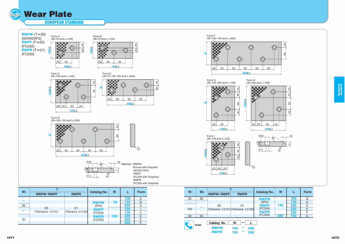
18721871
Eu
rop
ea
nS
tan
da
rd
EUROPEAN STANDARD
Wear Plate
RWPW (T 20)(SO#50SP2)RWPF (T 20)(FC250)RWPR (T 21)(FC250)
Catalog No.
RWPW(SP2)
RWPF(FC250)
RWPR(FC250)
70
100
W L Form
20(Tolerance a0.01)
21(Tolerance a0.25)
o
20
o
50
A
B
D
I
C
D
E
F
100150200100150200250300
TW1
RWPWYRWPF RWPR
Material : RWPW
Bronze with Graphite
(SO#50 SP2)
RWPF
(FC250 with Graphite)
RWPR
(FC250 with Graphite)
30˚
T
20 25 25
25
30
20
20 50
25
W1
W2
W1
20 25 25
25
25
25
25
20 50
300(L)
W
50 5050 50
W1
W
100(L)
15
0(W
)
50
150(L)
50
10
0(W
)
100(L)
14
11
20 12
R10
Form F(W=100 150 and L=300)
Form G(W=150 200 and L=100)
Form H(W=150 and L=150)
Form I(W=100 and L=100)
C3
25
20 25 25
30˚
T
20
25
W1
W1
25
20
25
20
2020
25
20
70
(W)
50
100(L)
70(W
)
50 50
150(L)
10
0(W
)
50
50
150(L)
W50 50 50
200(L)
W
50 50 50 50
250(L)
12
14
11
20
C3
R10
Form A(W=70 and L=100)
Form B(W=70 and L=150)
Form C(W=100 and L=150)
Form D(W=70 100 150 and L=200)
Form E(W=100 150 and L=250)
Catalog No.
RWPW(SP2)
RWPF(FC250)
RWPR(FC250)
150
200
W L
20(Tolerance a0.01)
21(Tolerance a0.25)
25
o
100
50
100150200250300100
TW1
50
o
50
W2
G
H
D
E
F
G
FormRWPWYRWPF RWPR
OrderCatalog No.
RWPWRWPR
W L
100150
200250
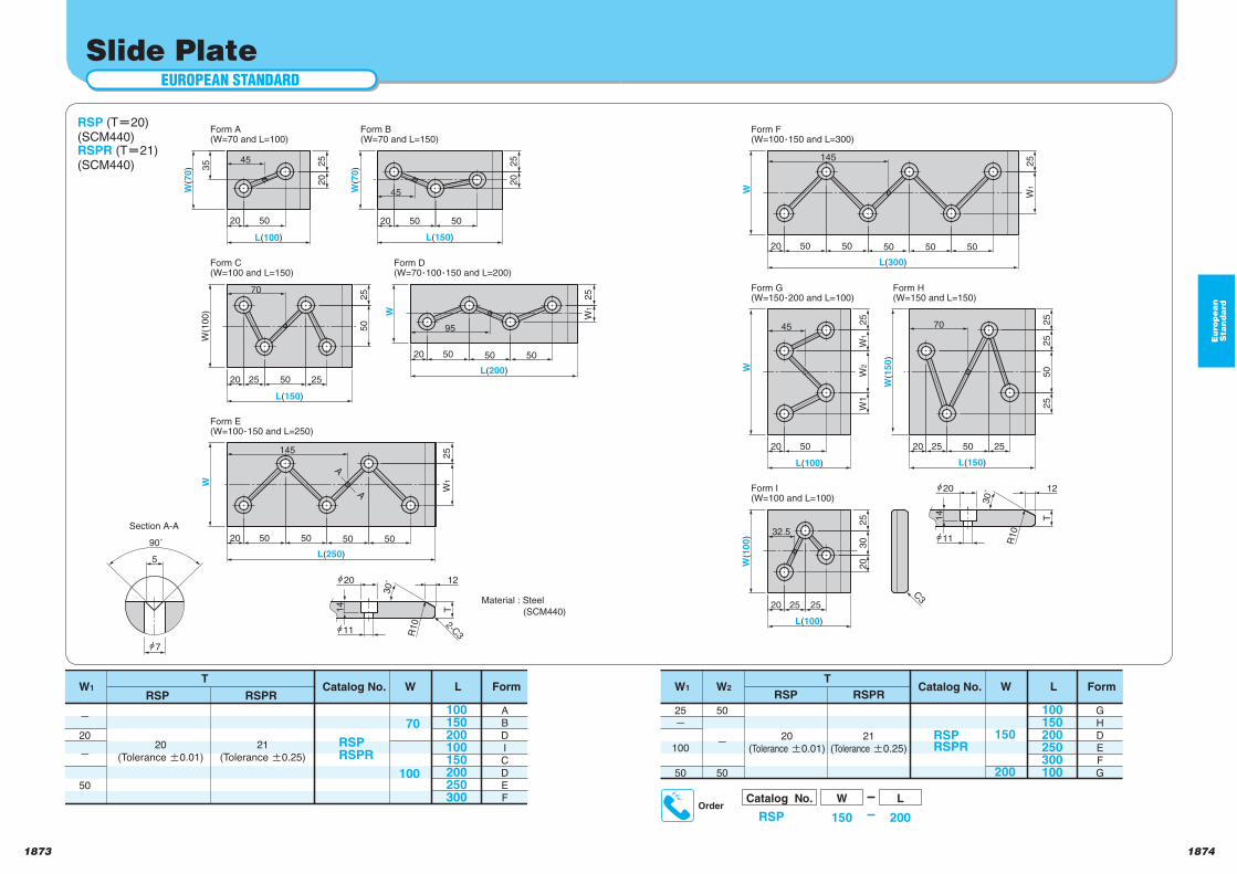
18741873
Eu
rop
ea
nS
tan
da
rd
EUROPEAN STANDARD
Slide Plate
RSP (T 20)(SCM440)RSPR (T 21)(SCM440)
Catalog No.
RSPRSPR
70
100
W L
20
(Tolerance a0.01)
21
(Tolerance a0.25)
o
20
o
50
100150200100150200250300
TW1
A
B
D
I
C
D
E
F
FormRSP RSPR
Material : Steel
(SCM440)
11
T
25
W1
W2
W1
32.5
20
25
25 25
20
20
20 20 25 25
25
25
25
25
50
L(300)
W
50 5050 50
W1
W
50
L(100)
W(1
50)
50
L(150)
50
W(1
00
)
L(100)
30
C3
Form F(W=100Y150 and L=300)
Form G(W=150Y200 and L=100)
Form H(W=150 and L=150)
Form I(W=100 and L=100)
145
45 70
30˚
14
h20 12
R10
90˚
5
7
Section A-A
11
25
W1
20 50
25
25
20
25
20
20
25
50
20 25 50
20
25
20
W(7
0)
50
L(100)
W(7
0)
50 50
L(150)
W(1
00
)
L(150)W
50 50
L(200)
W
50 50 50 50
W1
L(250)
2-C3
Form A(W=70 and L=100)
Form B(W=70 and L=150)
Form C(W=100 and L=150)
Form D(W=70Y100Y150 and L=200)
Form E(W=100Y150 and L=250)
35 45
70
95
145
A
A
45
30˚
T
12
14
h20
R10
Catalog No.
RSPRSPR
150
200
W L
20
(Tolerance a0.01)
21
(Tolerance a0.25)
25
o
100
50
100150200250300100
TW1
50
o
50
W2
G
H
D
E
F
G
FormRSP RSPR
OrderCatalog No.
RSP
W L
150 200
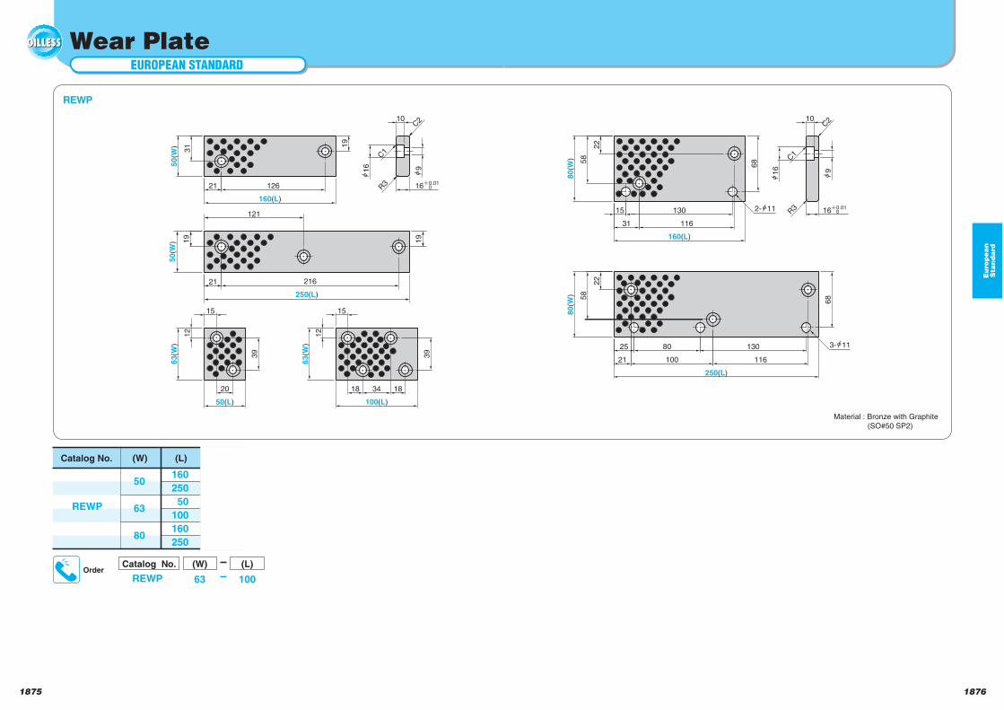
18761875
EUROPEAN STANDARD
Wear Plate
21
25
22
22
20 1818
19
21
160(L)
31
50
(W)
126
15
12
39
63(W
)
50(L)
15
34
100(L)
12
39
63(W
)
58
80(W
)
15
31 116
130 16 0.010
10
R3
58
68
100 116
80 130
2- 11
3- 11
80(W
)
16 9
68
160(L)
250(L)
10
16 R3 0.01
0
916
C1
C2
C1
C2
19
50
(W)
21 216
19
250(L)
121
REWP
Material : Bronze with Graphite
(SO#50 SP2)
Catalog No.
REWP
50
63
80
(W)
160
250
50
100
160
250
(L)
Eu
rop
ea
nS
tan
da
rd
OrderCatalog No.
REWP
(W) (L)
63 100
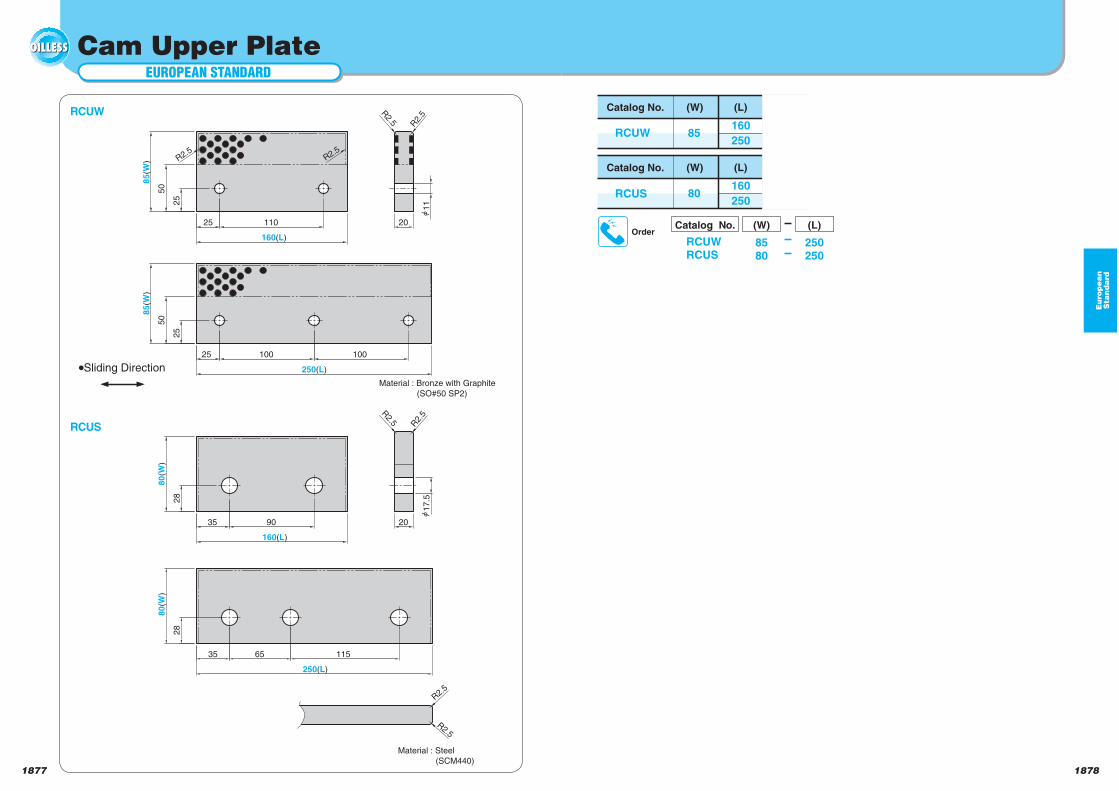
18781877
Eu
rop
ea
nS
tan
da
rd
EUROPEAN STANDARD
Cam Upper Plate
112
5
50
85(W
)
25
50
85(W
)
25 110
160(L)
25 100 100
250(L)
20
R2.
5R2.5
R2.5R2.5
RCUW Catalog No.
RCUW 85
(W)
160
250
(L)
Catalog No.
RCUS 80
(W)
160
250
(L)
Material : Steel
(SCM440)
20
17
.5
R2.5 R
2.5
28
80
(W)
35 90
160(L)
28
80(W
)
35 65 115
250(L)
R2.5
R2.5
Sliding Direction
RCUS
Material : Bronze with Graphite
(SO#50 SP2)
OrderCatalog No.
RCUWRCUS
(W) (L)
8580
250250
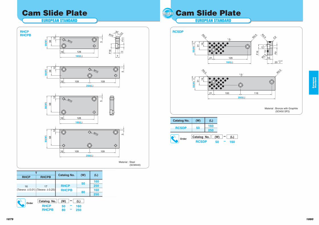
18801879
50
(W)
19
21
R3.
521
19
31
126
160(L)
50(W
) 0
.05
0
R3.5 R
3.5
20
916
0.010
250(L)
100
0.0
50
R3.5 R
3.5
116
31
10
1.6
1.6
1.6
C2
C1
R3.5
Eu
rop
ea
nS
tan
da
rd
EUROPEAN STANDARD
Cam Slide Plate
16
16
16
T
161
2
38
50(W
)
128
160(L)1
2
38
50
(W)
109 109
250(L)
12
68
80(W
)
128
160(L)
109 109
250(L)
12
68
80(W
)
11
30˚
5
R10
M10
11
18
55
5
M10
M10
M10
C2RHCPRHCPB
Catalog No.
RHCP
RHCPB
50
80
(W) (L)
16
(Tolerance 0.01)
17
(Tolerance 0.25)
160
250
160
250
T
RHCP RHCPB
RCSDP
Material : Steel
(SCM440)
EUROPEAN STANDARD
Material : Bronze with Graphite
(SO#50 SP2)
Catalog No.
RCSDP 50
(W)
160
250
(L)
Cam Slide Plate
OrderCatalog No.
RCSDP
(W) (L)
50 160
OrderCatalog No.
RHCPRHCPB
(W) (L)
5080
160250
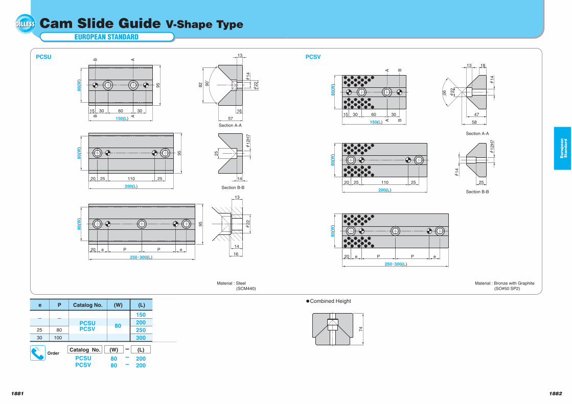
18821881
Eu
rop
ea
nS
tan
da
rd
EUROPEAN STANDARD
Cam Slide Guide V-Shape Type
PCSU
Material : Steel
(SCM440)
Catalog No.
PCSUPCSV
80
(W)
150
200
250
300
(L)
80
100
P
25
30
e
95
82
95
95
20 e14
16
13
22
16
13
2520 25
15 30
A
BB
A
Section A-A
Section B-B
80(W
)
60 30
150(L)
90
˚ h1
4
57
25
110
200(L)
h1
2H
7h
22
P P e
250Y300(L)
80(W
)8
0(W
)
14
e20
2520 25
13 18
22
250Y300(L)
P
60
150(L)
200(L)
110
80(W
)8
0(W
)8
0(W
)
15 30
BB
P e
25
30
AA
Section A-A
Section B-B
90˚
h1
4
47
58
h1
4
h1
2H
7
Material : Bronze with Graphite
(SO#50 SP2)
PCSV
74
Combined Height
OrderCatalog No.
PCSUPCSV
(W) (L)
8080
200200
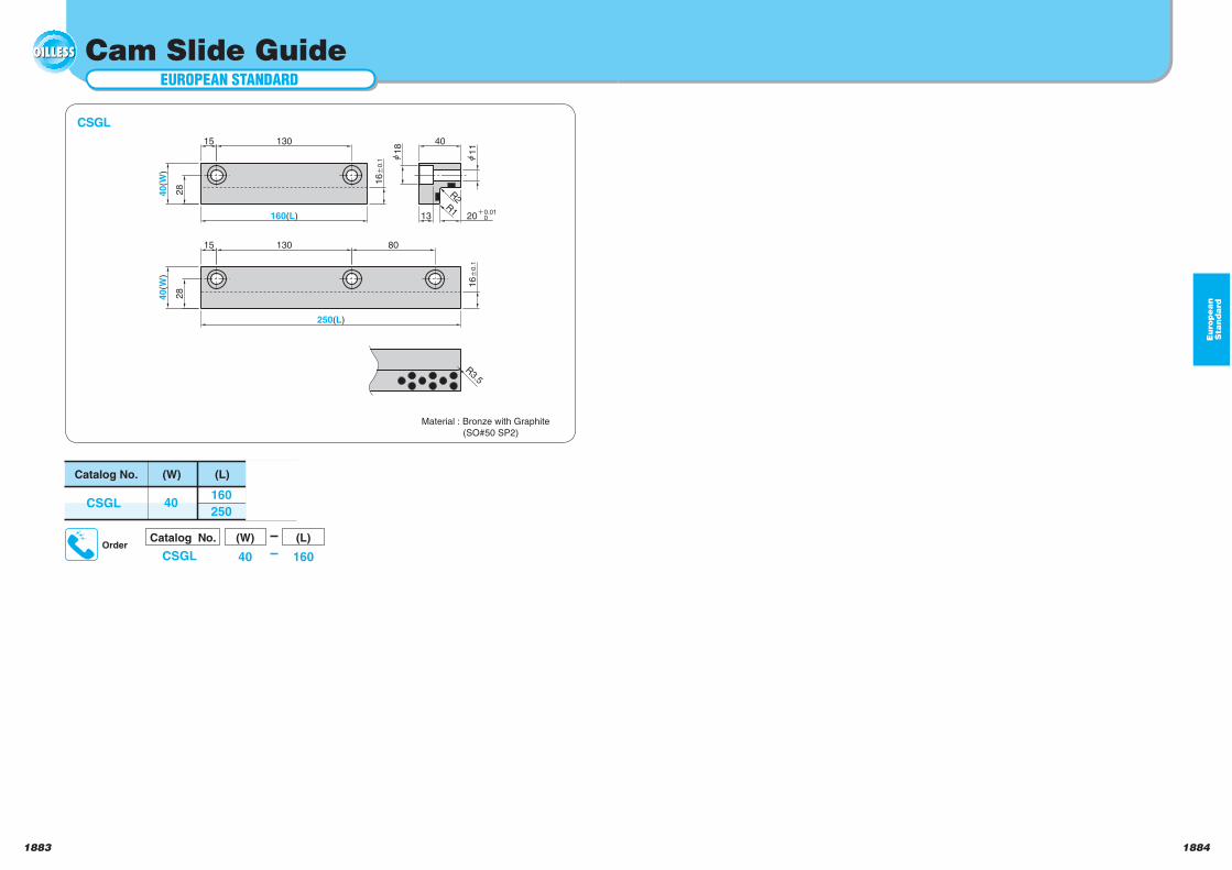
18841883
Eu
rop
ea
nS
tan
da
rd
EUROPEAN STANDARD
Cam Slide Guide
16a
0.1
16a
0.1
15
13
15 130
40(W
)
160(L)
40
20 i0.01
0
h1
8
h1
1
R2
R1
130 80
250(L)
40(W
)
28
28
R3.5
CSGL
Material : Bronze with Graphite
(SO#50 SP2)
Catalog No.
CSGL 40
(W)
160
250
(L)
OrderCatalog No.
CSGL
(W) (L)
40 160
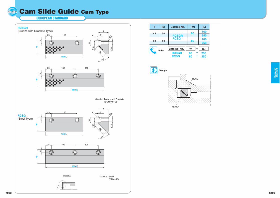
18861885
Eu
rop
ea
nS
tan
da
rd
EUROPEAN STANDARD
Cam Slide Guide Cam Type
25
25
25
45˚
25
25
25 110
160(L)
W
18
11
12
(S)
T
C3
110
160(L)
12
W
(S)
45˚
1118
T
C3
12
W
100 100
250(L)
12
W
100 100
250(L)
13
13
A
A
Detail A
C1
RCSGR(Bronze with Graphite Type)
Material : Bronze with Graphite
(SO#50 SP2)
Material : Steel
(SCM440)
Catalog No.
RCSGRRCSG
60
80
(W)
160
250
160
250
(L)
45
60
T
50
80
(S)
OrderCatalog No.
RCSGRRCSG
W (L)
6060
250250
Example
RCSGR
RCSG
RCSG(Steel Type)
Te
ch
nic
al D
ata
Technical data
Technical Data
Technical Data
1888
Te
ch
nic
al D
ata
Types and Features of Oilless Bearing ……………………………………………P.1889
Special Solid Lubricant Bearing ……………………………………………………P.1891
SO#50 Design Procedure ……………………………………………………………P.1893
SI Unit Conversion Table ……………………………………………………………P.1899
Fit Commonly Used ……………………………………………………………………P.1900
Tolerances of Commonly Used Hole Fits (Hole) ……………………… P.1901 to 1902
Tolerances of Commonly Used Hole Fits(Shaft) ……………………… P.1903 to 1904
JIS Limit and Fits Tolerance (Hole) …………………………………………………P.1905
JIS Limit and Fits Tolerance(Shaft) …………………………………………………P.1906
General Dimensional Tolerance ………………………………………… P.1907 to 1908
Surface Roughness ……………………………………………………………………P.1909
Surface Roughness by Different Processes (Reference) ………………………P.1910
Hardness conversion table ……………………………………………… P.1911 to 1912
Diameters of Straight Bolt Holes and Counterbore Holes ……………………P.1913
Dimensions of Hexagon Socket Head Bolt Holes (Reference) ………………P.1914
Hexagon Socket Head Bolt ……………………………………………… P.1915 to 1916
Hexagon Bolt ……………………………………………………………………………P.1917
Hexagon Nut ……………………………………………………………………………P.1918
Conversion Table of Trigometrical Function ………………………… P.1919 to 1920
Surface Area Calculation of Plane Figure …………………………………………P.1921
Calculation of Cubic Volume and Surface …………………………………………P.1922
Steel Materials ……………………………………………………………… P.1923 to 1926
Non-Ferrous Materials …………………………………………………… P.1927 to 1928
Calculation Standard of Punching Force ……………………………… P.1929 to 1930
How to Calculate Blank Size for Draw Die ……………………………… P.1931 to 1934
Material Property for Stamping ………………………………………… P.1935 to 1936
Comparison of Materials between JIS and Foreigh Standard ……… P.1939 to 1944
Steel Brandes Comparison Table …………………………………………………P.1945
1887
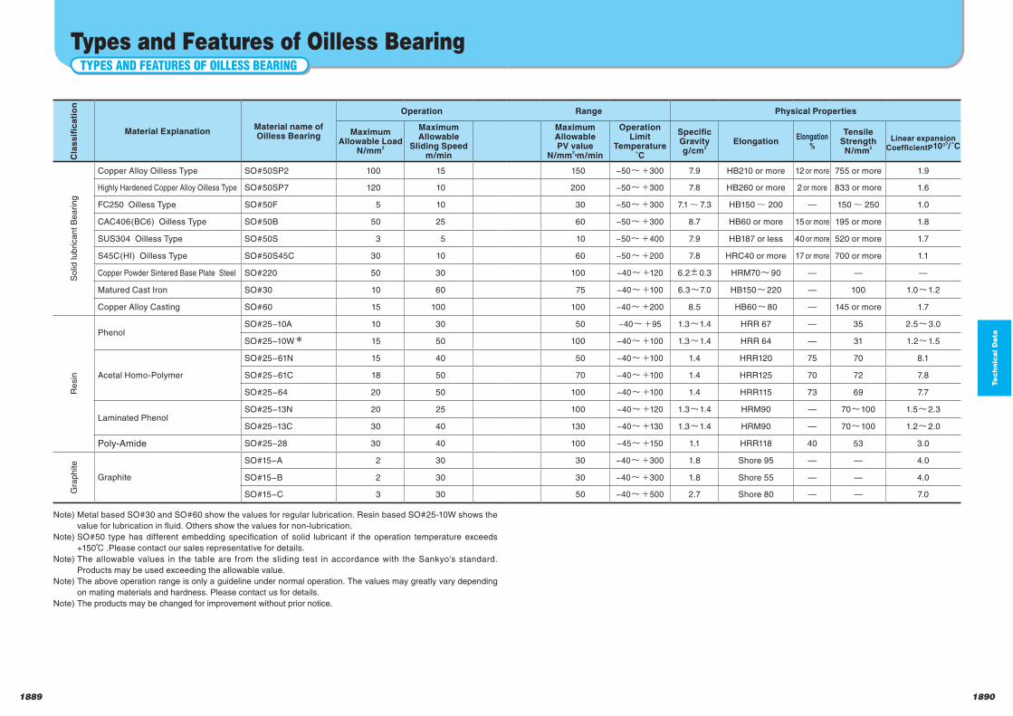
Te
ch
nic
al D
ata
18901889
TYPES AND FEATURES OF OILLESS BEARING
Types and Features of Oilless Bearing
Note) Metal based SO#30 and SO#60 show the values for regular lubrication. Resin based SO#25-10W shows the
value for lubrication in fluid. Others show the values for non-lubrication.
Note) SO#50 type has different embedding specification of solid lubricant if the operation temperature exceeds
+150℃ .Please contact our sales representative for details.
Note) The allowable values in the table are from the sliding test in accordance with the Sankyo's standard.
Products may be used exceeding the allowable value.
Note) The above operation range is only a guideline under normal operation. The values may greatly vary depending
on mating materials and hardness. Please contact us for details.
Note) The products may be changed for improvement without prior notice.
Material ExplanationMaterial name ofOilless Bearing
Operation Range Physical Properties
MaximumAllowable Load
N/mm2
MaximumAllowable
Sliding Speedm/min
MaximumAllowablePV value
N/mm2・m/min
OperationLimit
Temperature˚C
SpecificGravityg/cm
3Elongation
Elongation%
TensileStrengthN/mm
2
Linear expansionCoefficientP10O5
/ ˚C
Copper Alloy Oilless Type SO#50SP2 100 15 150 −50 300 7.9 HB210 or more 12 or more 755 or more 1.9
Highly Hardened Copper Alloy Oilless Type SO#50SP7 120 10 200 −50 300 7.8 HB260 or more 2 or more 833 or more 1.6
FC250 Oilless Type SO#50F 5 10 30 −50 300 7.1~ 7.3 HB150~ 200 — 150~ 250 1.0
CAC406(BC6) Oilless Type SO#50B 50 25 60 −50 300 8.7 HB60 or more 15 or more 195 or more 1.8
SUS304 Oilless Type SO#50S 3 5 10 −50 400 7.9 HB187 or less 40 or more 520 or more 1.7
S45C(HI) Oilless Type SO#50S45C 30 10 60 −50 200 7.8 HRC40 or more 17 or more 700 or more 1.1
Copper Powder Sintered Base Plate Steel SO#220 50 30 100 −40 120 6.2 0.3 HRM70 90 — — —
Matured Cast Iron SO#30 10 60 75 −40 100 6.3 7.0 HB150 220 — 100 1.0 1.2
Copper Alloy Casting SO#60 15 100 100 −40 200 8.5 HB60 80 — 145 or more 1.7
PhenolSO#25−10A 10 30 50 −40 95 1.3 1.4 HRR 67 — 35 2.5 3.0
SO#25−10W 15 50 100 −40 100 1.3 1.4 HRR 64 — 31 1.2 1.5
Acetal Homo-Polymer
SO#25−61N 15 40 50 −40 100 1.4 HRR120 75 70 8.1
SO#25−61C 18 50 70 −40 100 1.4 HRR125 70 72 7.8
SO#25−64 20 50 100 −40 100 1.4 HRR115 73 69 7.7
Laminated Phenol SO#25−13N 20 25 100 −40 120 1.3 1.4 HRM90 — 70 100 1.5 2.3
SO#25−13C 30 40 130 −40 130 1.3 1.4 HRM90 — 70 100 1.2 2.0
Poly-Amide SO#25−28 30 40 100 −45 150 1.1 HRR118 40 53 3.0
Graphite
SO#15−A 2 30 30 −40 300 1.8 Shore 95 — — 4.0
SO#15−B 2 30 30 −40 300 1.8 Shore 55 — — 4.0
SO#15−C 3 30 50 −40 500 2.7 Shore 80 — — 7.0
So
lid lu
brica
nt
Be
arin
gR
esin
G
rap
hite
C
las
sifi
ca
tio
n
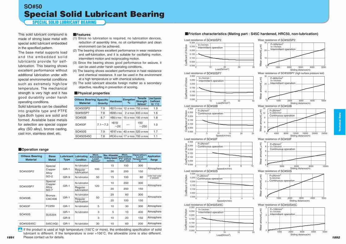
Te
ch
nic
al D
ata
18921891
SPECIAL SOLID LUBRICANT BEARING
SO#50
Special Solid Lubricant Bearing
This solid lubricant compound is
made of strong base metal with
special solid lubricant embedded
in the specified pattern.
The base metal supports load
a n d t h e e m b e d d e d s o l i d
lubricants provide for self-
lubrication. This bearing shows
excellent performance without
additional lubrication under with
special environmental conditions
such as extremely high/low
temperature. The mechanical
strength is very high and it has
good durability under harsh
operating conditions.
Solid lubricants can be classified
into graphite type and PTFE
type.Both types are solid and
formed. Available base metals
for selection are special copper
alloy (SO alloy), bronze casting,
cast iron, stainless steel, etc.
Features(1) Since no lubrication is required, no lubrication devices,
reduction of assembly time, no oil contamination and clean
environment can be achieved.
(2) The bearing shows excellent performance in wear resistance
and self-lubrication, and it is suitable for oscillating motion,
intermittent motion and reciprocating motion.
(3) Since the bearing shows good performance for seizure, it
can be used under harsh operating conditions.
(4) The bearing shows excellent performance in heat resistance
and chemical resistance. It can be used in the environment
at a high temperature or with chemical solutions.
(5) The solid lubricant absorbs foreign matter as a secondary
objective, resulting in prevention of scoring.
Friction characteristics (Mating part : S45C hardened, HRC50, non-lubrication)
SO#50SP2
SO#50SP7
SO#50B
SO#50F
SO#50S
SO#50S45C
Special
Copper
Alloy
SO-2
SpecialCopperAlloySO-7
Bronze
CAC406
FC250
SUS304
S45C(HQI)
GR-1
GR-9
GR-1
GR-1
GR-1
GR-1
GR-9
GR-1
No lubrication
No lubrication
No lubrication
No lubrication
No lubrication
No lubrication
No lubrication
100
50
120
50
5
3
3
30
15
30
15
10
20
25
20
10
5
10
10
150
200
100
200
250
60
100
30
10
20
60
300
150
80
300
150
300
150
300
400
150
200
Oilless Bearing
Material
Base
Metal
LubricantType
Lubricating
Condition
Max.Allowable
Load N/mm2
Max. AllowableSliding Speed
m/min
Max.AllowablePV valueN/mm2
Ym/min
OperationLimit
Temperature˚C
Application
Range
Atmosphere
Atmosphere
Atmosphere
Atmosphere
Atmosphere
Atmosphere
Atmosphere
Under fresh wateror seawater
Regularlubrication
Regularlubrication
Regularlubrication
Operation range
SO#50SP2
S0#50SP7
SO#50B
SO#50F
SO#50S
SO#50S45C
HB210 or more
HB260 or more
HB60 or more
HB150 n200
HB187 or less
HRC40 or more
12 or more
2 or more
15 or more
—
40 or more
17 or more
7.9
7.8
8.7
7.1n7.3
7.9
7.8
755 or more
833 or more
195 or more
150 n250
520 or more
700 or more
1.9
1.6
1.8
1.0
1.7
1.1
Oilless Bearing
Material
Specific
GravityHardness
Elongation%
TensileStrength N/mm2
Linear ExpansionCoefficient10o5/˚C
Physical properties
0
10
20
30
0 1000 2000 3000 4000 5000
Sliding distance(m)
Wear
am
ount(l
m)
0.000
0.050
0.100
0.150
0.200
0.250
0.300
0 10 20 30 40Load(N/mm2)
Load resistance of SO#50SP2 Wear resistance of SO#50SP2
Coeffic
ient of fr
ictio
n
0
10
20
30
0 1000 2000 3000 4000 5000
Sliding distance(m)
Wear
am
ount(l
m)
0.000
0.050
0.100
0.150
0.200
0.250
0.300
0 10 20 30 40Load(N/mm2)
Coeffic
ient of fr
ictio
n
0
2
4
6
8
10
0 3000 6000 9000 12000Sliding distance(m)
Wear
am
ount(l
m)
0
3
6
9
12
15
0 4000 8000 12000 16000 20000 24000
Sliding distance(m)
Wear
am
ount(l
m)
0.000
0.050
0.100
0.150
0.200
0.250
0.300
0 2 4 6 8 10
Speed(m/min)
Coeffic
ient of fr
ictio
n
0.000
0.050
0.100
0.150
0.200
0.250
0.300
0 5 10 15 20 25Speed(m/min)
Coeffic
ient of fr
ictio
n
P=2N/mm2
V=10m/minContinuous operation
0
1
2
3
0 1000 2000 3000 4000 5000
Sliding distance(m)
Wear
am
ount(l
m)
0.000
0.050
0.100
0.150
0.200
0.250
0.300
0 5 10 15 20
Load(N/mm2)
Coeffic
ient of fr
ictio
n V=1m/minIntermittent operation
0
1
2
3
0 1000 2000 3000 4000 5000
Sliding distance(m)
Wear
am
ount(l
m)
Speed(m/min)
Coeffic
ient of fr
ictio
n
0.000
0.050
0.100
0.150
0.200
0.250
0.300
0 1 2 3 4 5
Load resistance of SO#50SP7 Wear resistance of SO#50SP7 (high surface pressure test)
Load resistance of SO#50B Wear resistance of SO#50B
Load resistance of SO#50F Wear resistance of SO#50F
Load resistance of SO#50S Wear resistance of SO#50S
Load resistance of SO#50S45C Wear resistance of SO#50S45C
P=15N/mm2
V=1m/minIntermittent operation
P=2N/mm2
V=5m/minContinuous operation
P=2N/mm2
Continuous operation
P=2N/mm2
Continuous operation
P=2N/mm2
Continuous operation
V=1m/minIntermittent operation
P=2N/mm2
V=20m/minContinuous operation
P=80N/mm2
V=1m/minIntermittent operation
V=1m/minIntermittent operation
P=50N/mm2
V=1m/minIntermittent operation
If the product is used at high temperature (150˚C or more), the embedding specification of solid lubricant is different. If the temperature is over +100˚C, the allowable zone is also different. Please contact us for details.
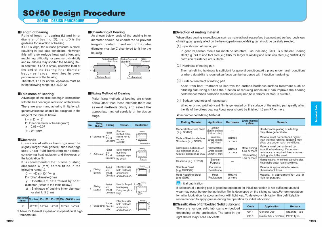
Te
ch
nic
al D
ata
18941893
SO#50 Design Procedure
Length of bearingRatio of length of bearing (L) and inner
diameter of bearing (D), i.e. L/D is the
guideline for selection of bearing.
If L/D is large, the surface pressure is small,
resulting in less load conditions. However,
this will also reduce heat radiation, and
machining difficulty for precise cylindricity
and roundness may shorten the bearing life.
In contrast, if L/D is small, eccentric load at
the end of the bearing inner diameter
b e c o m e s l a r g e , r e s u l t i n g i n p o o r
performance of the bearing.
Therefore, L/D for normal operation must be
in the following range: 0.5 <L/D <2
Thickness of BearingAdvantage of the slide bearing,in comparison
with the ball bearing,is reduction of thickness.
There are also manufacturing limitations.In
general,thickness should be designed in the
range of the formula below.
t D βD: Inner diameter of bearing(mm):0.05 0.07
β:2 5mm
ClearanceClearance of oil less bushings must be
slightly larger than general slide bearings
used under fluid lubricating conditions,
considering heat radiation and thickness of
the lubrication film.
It is recommended that oilless bushing
clearance C (mm) before f i t be in the
following range:ΔC γD s 10
- 3 ΔDs: Shaft diameter(mm)
γ : Coefficient determined by shaft
diameter (Refer to the table below.)
Δ : Shrinkage of bushing inner diameter
for shrink fit (mm)
Chamfering of BearingAs shown below, ends of the bushing inner
diameter should be chamfered to prevent
irregular contact. Insert end of the outer
diameter must be C chamfered to fit into the
housing.
Selection of mating material
When oilless bearing is used,factors such as material,hardness,surface treatment and surface roughness
of mating part greatly affect on the bearing performance.Mating part should be carefully selected.
Shaft Diameter(mm) 50 or less 50N180 180N250 250N500 500 or more
γ 2.0n3.0 1.5n3.0 1.5n2.5 1.5n2.5 1.0n2.5
RadialandThrustDirections
1
Standard method. Press cold fit, hot fit, etc. are available.
Effective with
both methods
of shrink fit
and adhesion.
RadialandThrustDirections
2
Easy method,
but fixing
strength may
be small.
RadialandThrustDirections
3
RadialandThrustDirections
4
Used for flanged
bushing only.
Fixing strength is
large.
ThrustDirectionOnly
5
Effective with
both methods
of shrink fit
and adhesion.
No.Fixing
MethodSliding Remark Illustration
Shrink Fit
Adhesion
Fixing
Bolt(1)
Fixing
Bolt(2)
Snap ring
Interference
Bu
sh
ing
Housing
Adhesive
Bu
sh
ing
Housing F
ixin
g B
olt
Bu
sh
ing
Housing
Fix
ing
Bo
lt
Bu
sh
ing
Housing
Bu
sh
ing
Housing
Sn
ap
Rin
g
Fixing Method of Dearing
Major fixing methods of bearing are shown
below.Other than these methods,there are
several methods.Study and select the
appropriate method carefully at the design
stage.
Allow for thermal expansion in operation at high
temperature.
Radius Chamfered(Both Ends)
C chamfered
Radius Chamfered(Both Ends)
C chamfered
RadiusChamfered
Classification of Embedded Solid Lubricant
There are various solid lubricants embedded
depending on the application. The table in the
right shows major solid lubricants.
【1】Specification of mating part
In general,carbon steels for machine structural use including S45C is sufficient.Bearing
steel,e.g. SUJ2 and tool steel,e.g.SK5 for larger durabilitiy,and stainless steel,e.g.SUS304,for
corrosion resistance are suitable.
【2】Hardness of mating part
Thermal refining hardness is sufficient for general conditions.At a place under harsh conditions
or where durability is required,surfaces can be hardened with induction hardening.
【3】Surface treatment of mating part
Apart from heat treatment to improve the surface hardness,surface treatment such as
nitriding,sulfurizing,etc.has the function of reducing adhesion.It can improve the bearing
performance.When corrosion resistance is required,hard chromium steel is suitable.
【4】Surface roughness of mating part
Whether or not solid lubricant film is generated on the surface of the mating part greatly affect
the life of the oilless bearing.Roughness should be finished 1.6 m RA or more.
Recommended Mating Material
Initial Lubrication
If selection of a mating part is good but operation for initial lubrication is not sufficient,unusual
wear may occur before the lubrication film is developed on the sliding surface.Perform operation
for initial lubrication for about an hour with light load.To develop a lubrication film definitely,it is
recommended to apply grease during the operation for initial lubrication.
Code Application Remark
GR-1
GR-9
General Use
Under Sea Water or Fresh Water
Graphite Type
PTFE Type
SO#50 DESIGN PROCEDURE
Mating Material Application HardnessSurface Roughness
mRmax Remark
General Structural Steel (e.g. SS400)
Light Duty(Surface pressure: 1 N/mm2 or less)
−
Metal sliding1.6a or more
Resin sliding0.8a or more
Hard chrome plating or nitridingmay allow general use.
Carbon Steel for MachineStructure (e.g. S35C)
General UseSurface pressure:
1 to 5 N/mm2
HRC25or more
Material must be hardened higherthan thermal refining. Nitriding mayallow use under harsh conditions.
Bearing steel such as SUJ2Tool steel such as SK5Alloy tool steel such as SKS3
Harsh ConditionsSurface pressure:5 N/mm2 or more
HRC45or more
Material must be hardened byinduction hardening. If corrosionresistance is required, hard chromeplating should be used.
Cast iron (e.g. FC250)Special Purpose
−Mating material for general stamping dies.Not suitable under harsh conditions.
Stainless Steel(e.g. SUS304)
CorrosionResistance
−Material is appropriate for use inchemical solutions.
Heat Resisting Steel(e.g. SUH3)
Heat Resistance
HRC45or more
Material is appropriate for use at high temperature.
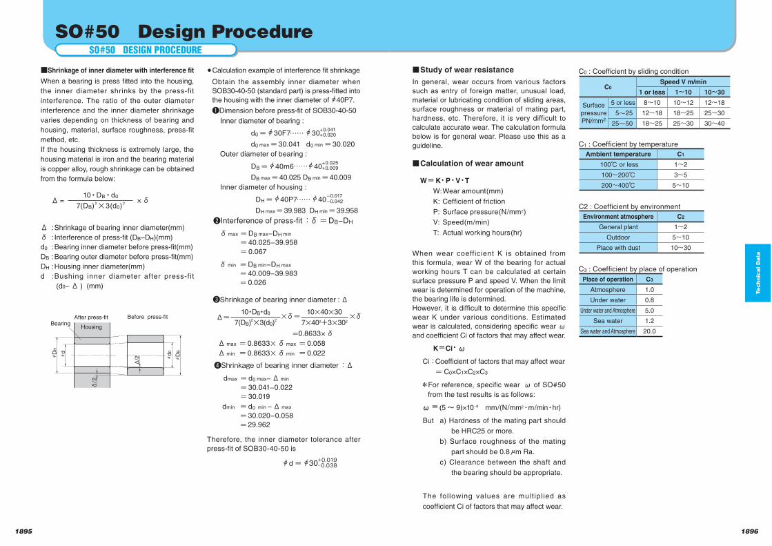
1895 1896
Te
ch
nic
al D
ata
SO#50 Design ProcedureSO#50 DESIGN PROCEDURE
Shrinkage of inner diameter with interference fit
When a bearing is press fitted into the housing,
the inner diameter shrinks by the press-fit
interference. The ratio of the outer diameter
interference and the inner diameter shrinkage
varies depending on thickness of bearing and
housing, material, surface roughness, press-fit
method, etc.
If the housing thickness is extremely large, the
housing material is iron and the bearing material
is copper alloy, rough shrinkage can be obtained
from the formula below:
Δ : Shrinkage of bearing inner diameter(mm)
δ : Interference of press-fit (DB−DH)(mm)
d0 : Bearing inner diameter before press-fit(mm)
DB : Bearing outer diameter before press-fit(mm)
DH : Housing inner diameter(mm)
d : Bushing inner diameter after press-fit
(d0−Δ ) (mm)
Calculation example of interference fit shrinkage
Obtain the assembly inner diameter when
SOB30-40-50 (standard part) is press-fitted into
the housing with the inner diameter of 40P7.
Dimension before press-fit of SOB30-40-50
Inner diameter of bearing :
d0 30F7…… 30+0.041+0.020
d0 max 30.041 d0 min 30.020
Outer diameter of bearing :
DB 40m6…… 40+0.025+0.009
DB max 40.025 DB min 40.009
Inner diameter of housing :
DH 40P7…… 40–0.017–0.042
DH max 39.983 DH min 39.958
Interference of press-fit :δ DB−DH
δmax DB max−DH min
40.025−39.958
0.067
Shrinkage of bearing inner diameter :Δ
0.8633×δ Δ max 0.8633 δmax 0.058
Δ min 0.8633 δmin 0.022
Shrinkage of bearing inner diameter :Δ
dmax d0 max−Δ min
30.041−0.022
30.019
Therefore, the inner diameter tolerance after
press-fit of SOB30-40-50 is
d= 30+0.019‒0.038
Study of wear resistance
In general, wear occurs from various factors
such as entry of foreign matter, unusual load,
material or lubricating condition of sliding areas,
surface roughness or material of mating part,
hardness, etc. Therefore, it is very difficult to
calculate accurate wear. The calculation formula
below is for general wear. Please use this as a
guideline.
Calculation of wear amount
W K P V T
W: Wear amount(mm)
K: Cefficient of friction
P: Surface pressure(N/mm2)
V: Speed(m/min)
T: Actual working hours(hr)
When wear coefficient K is obtained from
this formula, wear W of the bearing for actual
working hours T can be calculated at certain
surface pressure P and speed V. When the limit
wear is determined for operation of the machine,
the bearing life is determined.
However, it is difficult to determine this specific
wear K under various conditions. Estimated
wear is calculated, considering specific wear ω
and coefficient Ci of factors that may affect wear.
K Ci ω
Ci: Coefficient of factors that may affect wear
= C0×C1×C2×C3
For reference, specific wear ω of SO#50
from the test results is as follows:
ω (5~ 9)×10−8 mm/(N/mm2・m/min・hr)
But a) Hardness of the mating part should
be HRC25 or more.
b) Surface roughness of the mating
part should be 0.8 m Ra.
c) Clearance between the shaft and
the bearing should be appropriate.
The following values are multiplied as
coefficient Ci of factors that may affect wear.
C0 : Coefficient by sliding condition
C1 : Coefficient by temperature
C2 : Coefficient by environment
C3 : Coefficient by place of operation
C0Speed V m/min
1 or less 1 10 10 30
Surfacepressure PN/mm2
5 or less 8 10 10 12 12 18
5 25 12 18 18 25 25 30
25 50 18 25 25 30 30 40
Ambient temperature C1
100℃ or less 1 2
100 200℃ 3 5
200 400℃ 5 10
Environment atmosphere C2
General plant 1 2
Outdoor 5 10
Place with dust 10 30
Place of operation C3
Atmosphere 1.0
Under water 0.8
Under water and Atmosphere 5.0
Sea water 1.2
Sea water and Atmosphere 20.0
hd
hD
H
hd
0
hD
B
Δ/2
δ/2
HousingBearing
Before press-fit After press-fit
Δ =10 DB d0
×δ7(DB)
23(d0)
2
Δ10 DB d0 δ 10 40 30 δ
7(DB)2
3(d0)2
7 402+3 302
δmin DB min−DH max
40.009−39.983
0.026
dmin d0 min −Δ max
30.020−0.058
29.962
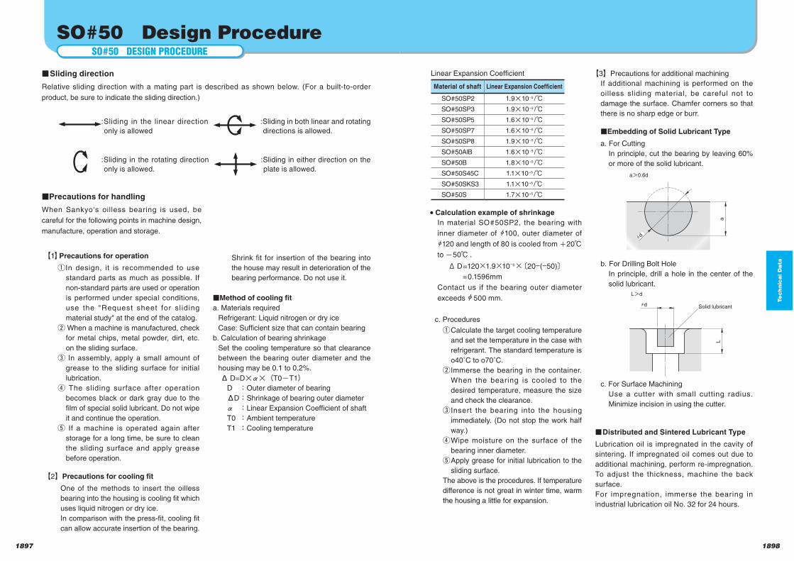
1897 1898
Te
ch
nic
al D
ata
Sliding direction Relative sliding direction with a mating part is described as shown below. (For a built-to-order
product, be sure to indicate the sliding direction.)
SO#50 Design ProcedureSO#50 DESIGN PROCEDURE
【1】Precautions for operation
In design, it is recommended to use
standard parts as much as possible. If
non-standard parts are used or operation
is performed under special conditions,
use the "Request sheet for sl iding
material study" at the end of the catalog.
When a machine is manufactured, check
for metal chips, metal powder, dirt, etc.
on the sliding surface.
In assembly, apply a small amount of
grease to the sliding surface for initial
lubrication.
The sliding surface after operation
becomes black or dark gray due to the
film of special solid lubricant. Do not wipe
it and continue the operation.
If a machine is operated again after
storage for a long time, be sure to clean
the sliding surface and apply grease
before operation.
【2】Precautions for cooling fit
One of the methods to insert the oilless
bearing into the housing is cooling fit which
uses liquid nitrogen or dry ice.
In comparison with the press-fit, cooling fit
can allow accurate insertion of the bearing.
Shrink fit for insertion of the bearing into
the house may result in deterioration of the
bearing performance. Do not use it.
Method of cooling fit
a. Materials required
Refrigerant: Liquid nitrogen or dry ice
Case: Sufficient size that can contain bearing
b. Calculation of bearing shrinkage
Set the cooling temperature so that clearance
between the bearing outer diameter and the
housing may be 0.1 to 0.2%.
Δ D=D (T0 T1) D :Outer diameter of bearing
ΔD :Shrinkage of bearing outer diameter
:Linear Expansion Coefficient of shaft
T0 :Ambient temperature
T1 :Cooling temperature
Calculation example of shrinkage In material SO#50SP2, the bearing with
inner diameter of 100, outer diameter of
120 and length of 80 is cooled from 20℃
to 50℃ .
ΔD=120 1.9 10−5 〔20−(−50)〕 =0.1596mm
Contact us if the bearing outer diameter
exceeds 500 mm.
c. Procedures
Calculate the target cooling temperature
and set the temperature in the case with
refrigerant. The standard temperature is
o40˚C to o70˚C.
Immerse the bearing in the container.
When the bearing is cooled to the
desired temperature, measure the size
and check the clearance.
Insert the bearing into the housing
immediately. (Do not stop the work half
way.)
Wipe moisture on the surface of the
bearing inner diameter.
Apply grease for initial lubrication to the
sliding surface.
The above is the procedures. If temperature
difference is not great in winter time, warm
the housing a little for expansion.
【3】Precautions for additional machining
If additional machining is performed on the
oilless sliding material, be careful not to
damage the surface. Chamfer corners so that
there is no sharp edge or burr.
Embedding of Solid Lubricant Type
a. For Cutting
In principle, cut the bearing by leaving 60%
or more of the solid lubricant.
b. For Drilling Bolt Hole
In principle, drill a hole in the center of the
solid lubricant.
c. For Surface Machining
Use a cutter with small cutting radius.
Minimize incision in using the cutter.
Distributed and Sintered Lubricant Type
Lubrication oil is impregnated in the cavity of
sintering. If impregnated oil comes out due to
additional machining, perform re-impregnation.
To adjust the thickness, machine the back
surface.
For impregnation, immerse the bearing in
industrial lubrication oil No. 32 for 24 hours.
hd
a
a>0.6d
>
Material of shaft Linear Expansion Coefficient
SO#50SP2 1.9 10–5 /℃SO#50SP3 1.9 10–5 /℃SO#50SP5 1.6 10–5 /℃SO#50SP7 1.6 10–5 /℃SO#50SP8 1.9 10–5 /℃SO#50AlB 1.6 10–5 /℃SO#50B 1.8 10–5 /℃SO#50S45C 1.1 10–5 /℃SO#50SKS3 1.1 10–5 /℃SO#50S 1.7 10–5 /℃
Linear Expansion Coefficient
>hd
L
L>d
Solid lubricant
Precautions for handling
When Sankyo's oilless bearing is used, be
careful for the following points in machine design,
manufacture, operation and storage.
:Sliding in either direction on the
plate is allowed.
:Sliding in both linear and rotating
directions is allowed.
:Sliding in the rotating direction
only is allowed.
:Sliding in the linear direction
only is allowed
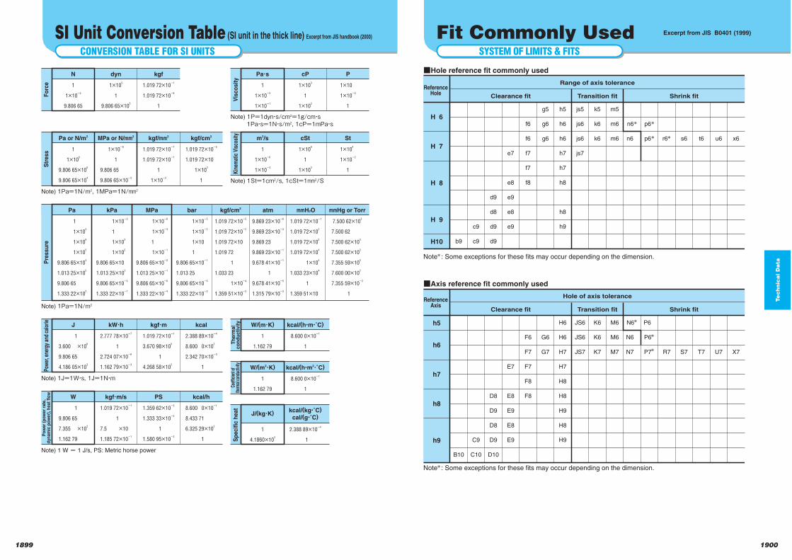
Te
ch
nic
al D
ata
19001899
Note : Some exceptions for these fits may occur depending on the dimension.
Range of axis tolerance
Clearance fit Transition fit Shrink fit
ReferenceHole
qHole reference fit commonly used
b9
H 6
H 7
H 8
H 9
H10
c9
c9
d9
d8
d9
d9
e7
e8
e9
e8
e9
f6
f6
f7
f7
f8
g5
g6
g6
h5
h6
h6
h7
h7
h8
h8
h9
js5
js6
js6
js7
k5
k6
k6
m5
m6
m6
n6
n6
p6
p6 r6 s6 t6 u6 x6
Hole of axis tolerance
Clearance fit Transition fit Shrink fit
qAxis reference fit commonly used
B10
h5
h6
h7
h8
h9 C9
C10
D8
D9
D8
D9
D10
E7
E8
E9
E8
E9
F6
F7
F7
F8
F8
G6
G7
H6
H6
H7
H7
H8
H8
H9
H8
H9
JS6
JS6
JS7
K6
K6
K7
M6
M6
M7
N6
N6
N7
P6
P6
P7 R7 S7 T7 U7 X7
Note : Some exceptions for these fits may occur depending on the dimension.
ReferenceAxis
SYSTEM OF LIMITS & FITS
Fit Commonly UsedCONVERSION TABLE FOR SI UNITS
SI Unit Conversion Table (SI unit in the thick line) Excerpt from JIS handbook (2000)
N
1
1×10⁻⁵
9.806 65
dyn
1×10⁵
1
9.806 65×105
kgf
1.019 72×10-1
1.019 72×10-6
1
Pa・s
1
1×10⁻³
1×10⁻¹
Note) 1P=1dyn・s/cm2=1g/cm・s1Pa・s=1N・s/m2, 1cP=1mPa・s
Note) 1St=1cm2/s, 1cSt=1mm2/S
Note) 1Pa=1N/m2, 1MPa=1N/mm2
cP
1×10³
1
1×10²
P
1×10
1×10⁻²
1
m2/s
1
1×10⁻⁶
1×10⁻⁴
cSt
1×10⁶
1
1×10²
St
1×10⁴
1×10⁻²
1
W/(m・K)
1
1.162 79
kcal/(h・m・C)
8.600 0×10-1
1
W/(m2・K)
1
1.162 79
kcal/(h・m2・C)
8.600 0×10-1
1
J/(kg・K)
1
4.1860×10³
kcal/(kg・C)
cal/(g・C)
2.388 89×10-4
1
Pa or N/m2
1
1×10⁶
9.806 65×106
9.806 65×104
MPa or N/mm2
1×10⁻⁶
1
9.806 65
9.806 65×10-2
kgf/mm2
1.019 72×10-7
1.019 72×10-1
1
1×10⁻²
kgf/cm2
1.019 72×10-5
1.019 72×10
1×10²
1
Note) 1J=1W・s, 1J=1N・m
J
1
3.600 ×10⁶
9.806 65
4.186 05×103
kW・h
2.777 78×10-7
1
2.724 07×10-6
1.162 79×10-3
kgf・m
1.019 72×10-1
3.670 98×105
1
4.268 58×102
kcal
2.388 89×10-4
8.600 0×102
2.342 70×10-3
1
Note) 1 W m 1 J/s, PS: Metric horse power
W
1
9.806 65
7.355 ×10²
1.162 79
kgf・m/s
1.019 72×10-1
1
7.5 ×10
1.185 72×10-1
PS
1.359 62×10-3
1.333 33×10-2
1
1.580 95×10-3
kcal/h
8.600 0×10-1
8.433 71
6.325 29×102
1
Note) 1Pa=1N/m2
Pa
1
1×10³
1×10⁶
1×10⁵
9.806 65×104
1.013 25×105
9.806 65
1.333 22×102
kPa
1×10⁻³
1
1×10³
1×10²
9.806 65×10
1.013 25×102
9.806 65×10-3
1.333 22×10-1
MPa
1×10⁻⁶
1×10⁻³
1
1×10⁻¹
9.806 65×10-2
1.013 25×10-1
9.806 65×10-6
1.333 22×10-4
bar
1×10⁻⁵
1×10⁻²
1×10
1
9.806 65×10-1
1.013 25
9.806 65×10-5
1.333 22×10-3
kgf/cm2
1.019 72×10-5
1.019 72×10-2
1.019 72×10
1.019 72
1
1.033 23
1×10⁻⁴
1.359 51×10-3
atm
9.869 23×10-6
9.869 23×10-3
9.869 23
9.869 23×10-1
9.678 41×10-1
1
9.678 41×10-5
1.315 79×10-3
mmH2O
1.019 72×10-1
1.019 72×102
1.019 72×105
1.019 72×104
1×10⁴
1.033 23×104
1
1.359 51×10
mmHg or Torr
7.500 62×103
7.500 62
7.500 62×103
7.500 62×102
7.355 59×102
7.600 00×102
7.355 59×10-2
1
Fo
rce
Vis
co
sit
yK
inem
atic
Vis
cosi
tyT
he
rma
lc
on
du
cti
vit
yCo
effic
ient
of
ther
mal
con
duct
ivity
Sp
ecif
ic h
eat
Str
ess
Pow
er, e
nerg
y an
d ca
lorie
Po
wer
(po
wer
rate
,d
yn
am
ic p
ow
er)
, h
eat
flo
wP
ressu
re
Excerpt from JIS B0401 (1999)
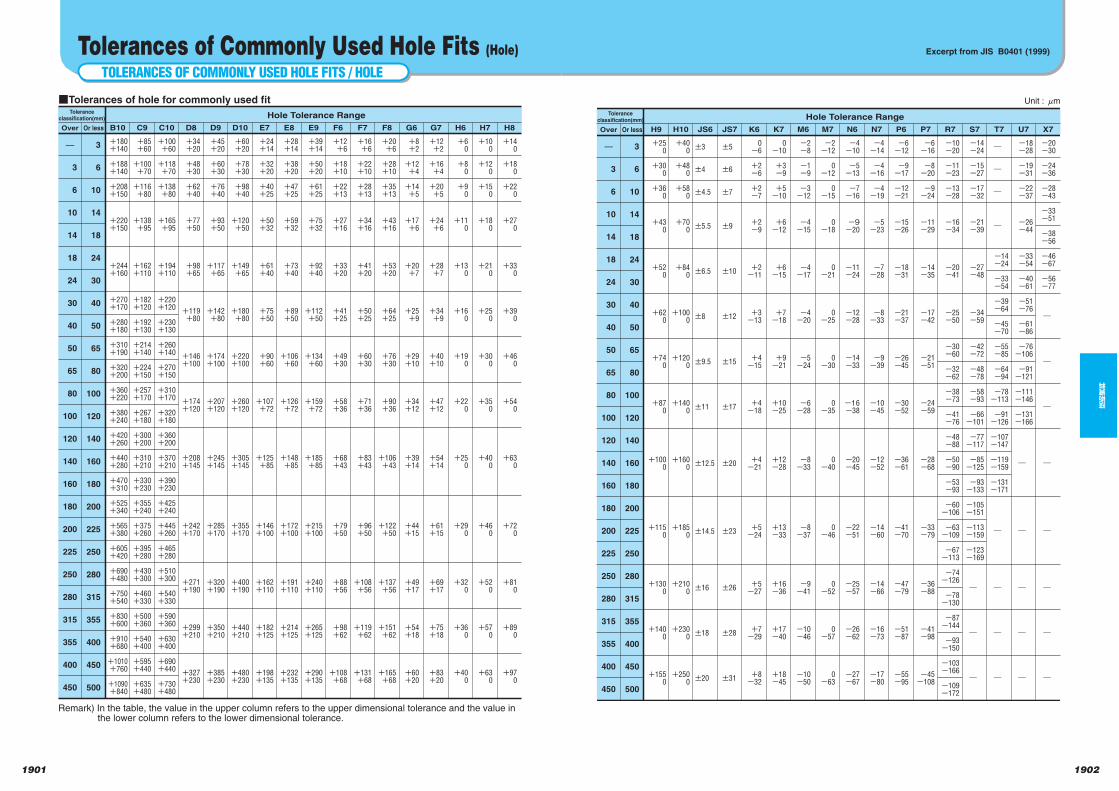
Te
ch
nic
al D
ata
1902
技術資料
1901
Unit : lm
Hole Tolerance RangeTolerance
classification(mm)
Over Or less H9
+25
0
+30
0
+36
0
+43
0
+52
0
+62
0
+74
0
+87
0
+100
0
+115
0
+130
0
+140
0
+155
0
H10
+40
0
+48
0
+58
0
+70
0
+84
0
+100
0
+120
0
+140
0
+160
0
+185
0
+210
0
+230
0
+250
0
JS6
±3
±4
±4.5
±5.5
±6.5
±8
±9.5
±11
±12.5
±14.5
±16
±18
±20
±5
±6
±7
±9
±10
±12
±15
±17
±20
±23
±26
±28
±31
JS7 K6
0
-6
+2
-6
+2
-7
+2
-9
+2
-11
+3
-13
+4
-15
+4
-18
+4
-21
+5
-24
+5
-27
+7
-29
+8
-32
0
-10
+3
-9
+5
-10
+6
-12
+6
-15
+7
-18
+9
-21
+10
-25
+12
-28
+13
-33
+16
-36
+17
-40
+18
-45
K7 M6
-2
-8
-1
-9
-3
-12
-4
-15
-4
-17
-4
-20
-5
-24
-6
-28
-8
-33
-8
-37
-9
-41
-10
-46
-10
-50
-2
-12
0
-12
0
-15
0
-18
0
-21
0
-25
0
-30
0
-35
0
-40
0
-46
0
-52
0
-57
0
-63
-4
-10
-5
-13
-7
-16
-9-20
-11
-24
-12
-28
-14
-33
-16
-38
-20
-45
-22
-51
-25
-57
-26
-62
-27
-67
-4
-14
-4
-16
-4
-19
-5
-23
-7
-28
-8
-33
-9
-39
-10
-45
-12
-52
-14
-60
-14
-66
-16
-73
-17
-80
-6
-12
-9
-17
-12
-21
-15
-26
-18
-31
-21
-37
-26
-45
-30
-52
-36
-61
-41
-70
-47
-79
-51
-87
-55
-95
M7 N6 N7 P6 P7
-6
-16
-8
-20
-9
-24
-11
-29
-14
-35
-17
-42
-21
-51
-24
-59
-28
-68
-33
-79
-36
-88
-41
-98
-45
-108
R7
-10
-20
-11
-23
-13
-28
-16
-34
-20
-41
-25
-50
-30
-60
-32
-62
-38
-73
-41
-76
-48
-88
-50
-90
-53
-93
-60
-106
-63
-109
-67
-113
-74
-126
-78
-130
-87
-144
-93
-150
-103
-166
-109
-172
S7
-14
-24
-15
-27
-17
-32
-21
-39
-27
-48
-34
-59
-42
-72
-48
-78
-58
-93
-66
-101
-77
-117
-85
-125
-93
-133
-105
-151
-113
-159
-123
-169
_
_
_
T7
_
_
_
_
-14
-24
-33
-54
-39
-64
-45
-70
-55
-85
-64
-94
-78
-113
-91
-126
-107
-147
-119
-159
-131
-171
_
_
_
_
U7
-18
-28
-19
-31
-22
-37
-26
-44
-33
-54
-40
-61
-51
-76
-61
-86
-76
-106
-91
-121
-111
-146
-131
-166
_
_
_
_
_
X7
-20
-30
-24
-36
-28
-43
-33
-51
-38
-56
-46
-67
-56
-77
_
_
_
_
_
_
_
_
3
6
10
14
18
24
30
40
50
65
80
100
120
140
160
180
200
225
250
280
315
355
400
450
3
6
10
14
18
24
30
40
50
65
80
100
120
140
160
180
200
225
250
280
315
355
400
450
500
Excerpt from JIS B0401 (1999)
TOLERANCES OF COMMONLY USED HOLE FITS / HOLE
Tolerances of Commonly Used Hole Fits (Hole)
Remark) In the table, the value in the upper column refers to the upper dimensional tolerance and the value in the lower column refers to the lower dimensional tolerance.
Hole Tolerance RangeTolerance
classification(mm)
Over Or less B10
qTolerances of hole for commonly used fit
+180
+140
+188
+140
+208
+150
+220
+150
+244
+160
+270
+170
+280
+180
+310
+190
+320
+200
+360
+220
+380
+240
+420
+260
+440
+280
+470
+310
+525
+340
+565
+380
+605
+420
+690
+480
+750
+540
+830
+600
+910
+680
+1010
+760
+1090
+840
C9
+85
+60
+100
+70
+116
+80
+138
+95
+162
+110
+182
+120
+192
+130
+214
+140
+224
+150
+257
+170
+267
+180
+300
+200
+310
+210
+330
+230
+355
+240
+375
+260
+395
+280
+430
+300
+460
+330
+500
+360
+540
+400
+595
+440
+635
+480
C10
+100
+60
+118
+70
+138
+80
+165
+95
+194
+110
+220
+120
+230
+130
+260
+140
+270
+150
+310
+170
+320
+180
+360
+200
+370
+210
+390
+230
+425
+240
+445
+260
+465
+280
+510
+300
+540
+330
+590
+360
+630
+400
+690
+440
+730
+480
D8
+34
+20
+48
+30
+62
+40
+77
+50
+98
+65
+119
+80
+146
+100
+174
+120
+208
+145
+242
+170
+271
+190
+299
+210
+327
+230
D9
+45
+20
+60
+30
+76
+40
+93
+50
+117
+65
+142
+80
+174
+100
+207
+120
+245
+145
+285
+170
+320
+190
+350
+210
+385
+230
D10
+60
+20
+78
+30
+98
+40
+120
+50
+149
+65
+180
+80
+220
+100
+260
+120
+305
+145
+355
+170
+400
+190
+440
+210
+480
+230
E7
+24
+14
+32
+20
+40
+25
+50
+32
+61
+40
+75
+50
+90
+60
+107
+72
+125
+85
+146
+100
+162
+110
+182
+125
+198
+135
E8
+28
+14
+38
+20
+47
+25
+59
+32
+73
+40
+89
+50
+106
+60
+126
+72
+148
+85
+172
+100
+191
+110
+214
+125
+232
+135
E9
+39
+14
+50
+20
+61
+25
+75
+32
+92
+40
+112
+50
+134
+60
+159
+72
+185
+85
+215
+100
+240
+110
+265
+125
+290
+135
F6
+12
+6
+18
+10
+22
+13
+27
+16
+33
+20
+41
+25
+49
+30
+58
+36
+68
+43
+79
+50
+88
+56
+98
+62
+108
+68
F7
+16
+6
+22
+10
+28
+13
+34
+16
+41
+20
+50
+25
+60
+30
+71
+36
+83
+43
+96
+50
+108
+56
+119
+62
+131
+68
F8
+20
+6
+28
+10
+35
+13
+43
+16
+53
+20
+64
+25
+76
+30
+90
+36
+106
+43
+122
+50
+137
+56
+151
+62
+165
+68
G6
+8
+2
+12
+4
+14
+5
+17
+6
+20
+7
+25
+9
+29
+10
+34
+12
+39
+14
+44
+15
+49
+17
+54
+18
+60
+20
G7
+12
+2
+16
+4
+20
+5
+24
+6
+28
+7
+34
+9
+40
+10
+47
+12
+54
+14
+61
+15
+69
+17
+75
+18
+83
+20
H6
+6
0
+8
0
+9
0
+11
0
+13
0
+16
0
+19
0
+22
0
+25
0
+29
0
+32
0
+36
0
+40
0
H7
+10
0
+12
0
+15
0
+18
0
+21
0
+25
0
+30
0
+35
0
+40
0
+46
0
+52
0
+57
0
+63
0
H8
+14
0
+18
0
+22
0
+27
0
+33
0
+39
0
+46
0
+54
0
+63
0
+72
0
+81
0
+89
0
+97
0
3
6
10
14
18
24
30
40
50
65
80
100
120
140
160
180
200
225
250
280
315
355
400
450
3
6
10
14
18
24
30
40
50
65
80
100
120
140
160
180
200
225
250
280
315
355
400
450
500
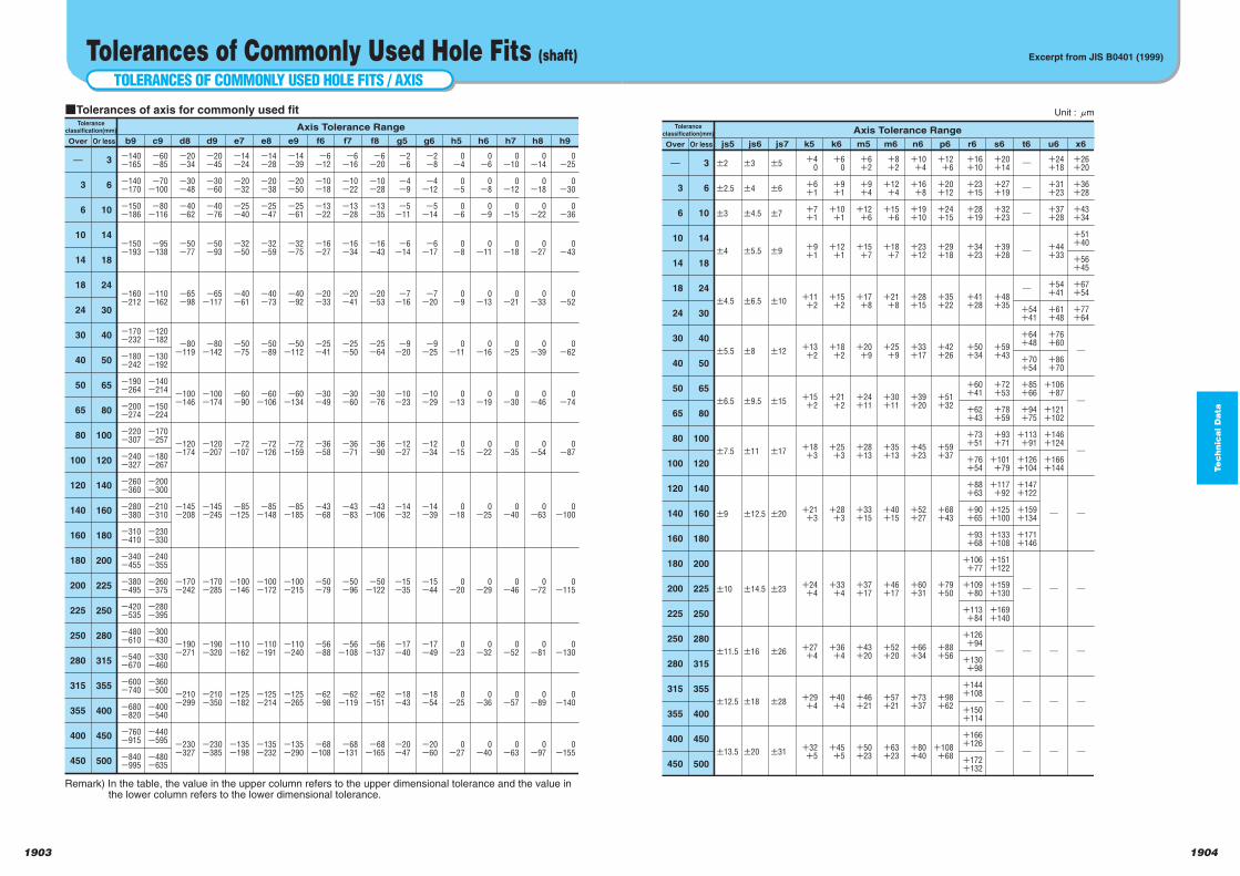
Te
ch
nic
al D
ata
19041903
Unit : lm
Axis Tolerance RangeTolerance
classification(mm)
Over Or less js5 js6 js7
±5
±6
±7
±9
±10
±12
±15
±17
±20
±23
±26
±28
±31
±3
±4
±4.5
±5.5
±6.5
±8
±9.5
±11
±12.5
±14.5
±16
±18
±20
±2
±2.5
±3
±4
±4.5
±5.5
±6.5
±7.5
±9
±10
±11.5
±12.5
±13.5
k5 k6
+6
0
+9
+1
+10
+1
+12
+1
+15
+2
+18
+2
+21
+2
+25
+3
+28
+3
+33
+4
+36
+4
+40
+4
+45
+5
+4
0
+6
+1
+7
+1
+9
+1
+11
+2
+13
+2
+15
+2
+18
+3
+21
+3
+24
+4
+27
+4
+29
+4
+32
+5
+6
+2
+9
+4
+12
+6
+15
+7
+17
+8
+20
+9
+24
+11
+28
+13
+33
+15
+37
+17
+43
+20
+46
+21
+50
+23
m5 m6
+8
+2
+12
+4
+15
+6
+18
+7
+21
+8
+25
+9
+30
+11
+35
+13
+40
+15
+46
+17
+52
+20
+57
+21
+63
+23
+10
+4
+16
+8
+19
+10
+23
+12
+28
+15
+33
+17
+39
+20
+45
+23
+52
+27
+60
+31
+66
+34
+73
+37
+80
+40
+12
+6
+20
+12
+24
+15
+29
+18
+35
+22
+42
+26
+51
+32
+59
+37
+68
+43
+79
+50
+88
+56
+98
+62
+108
+68
n6 p6 r6
+16
+10
+23
+15
+28
+19
+34
+23
+41
+28
+50
+34
+60
+41
+62
+43
+73
+51
+76
+54
+88
+63
+90
+65
+93
+68
+106
+77
+109
+80
+113
+84
+126
+94
+130
+98
+144
+108
+150
+114
+166
+126
+172
+132
s6
+20
+14
+27
+19
+32
+23
+39
+28
+48
+35
+59
+43
+72
+53
+78
+59
+93
+71
+101
+79
+117
+92
+125
+100
+133
+108
+151
+122
+159
+130
+169
+140
_
_
_
t6
_
_
_
_
_
+54
+41
+64
+48
+70
+54
+85
+66
+94
+75
+113
+91
+126
+104
+147
+122
+159
+134
+171
+146
_
_
_
_
u6
+24
+18
+31
+23
+37
+28
+44
+33
+54
+41
+61
+48
+76
+60
+86
+70
+106
+87
+121
+102
+146
+124
+166
+144
_
_
_
_
_
x6
+26
+20
+36
+28
+43
+34
+51
+40
+56
+45
+67
+54
+77
+64
_
_
_
_
_
_
_
_
3
6
10
14
18
24
30
40
50
65
80
100
120
140
160
180
200
225
250
280
315
355
400
450
3
6
10
14
18
24
30
40
50
65
80
100
120
140
160
180
200
225
250
280
315
355
400
450
500
Excerpt from JIS B0401 (1999)
TOLERANCES OF COMMONLY USED HOLE FITS / AXIS
Tolerances of Commonly Used Hole Fits (shaft)
Remark) In the table, the value in the upper column refers to the upper dimensional tolerance and the value in the lower column refers to the lower dimensional tolerance.
Axis Tolerance RangeTolerance
classification(mm)
Over Or less b9
qTolerances of axis for commonly used fit
-140
-165
-140
-170
-150
-186
-150
-193
-160
-212
-170
-232
-180
-242
-190
-264
-200
-274
-220
-307
-240
-327
-260
-360
-280
-380
-310
-410
-340
-455
-380
-495
-420
-535
-480
-610
-540
-670
-600
-740
-680
-820
-760
-915
-840
-995
c9
-60
-85
-70
-100
-80
-116
-95
-138
-110
-162
-120
-182
-130
-192
-140
-214
-150
-224
-170
-257
-180
-267
-200
-300
-210
-310
-230
-330
-240
-355
-260
-375
-280
-395
-300
-430
-330
-460
-360
-500
-400
-540
-440
-595
-480
-635
d8
-20
-34
-30
-48
-40
-62
-50
-77
-65
-98
-80
-119
-100
-146
-120
-174
-145
-208
-170
-242
-190
-271
-210
-299
-230
-327
d9
-20
-45
-30
-60
-40
-76
-50
-93
-65
-117
-80
-142
-100
-174
-120
-207
-145
-245
-170
-285
-190
-320
-210
-350
-230
-385
e7
-14
-24
-20
-32
-25
-40
-32
-50
-40
-61
-50
-75
-60
-90
-72
-107
-85
-125
-100
-146
-110
-162
-125
-182
-135
-198
e8
-14
-28
-20
-38
-25
-47
-32
-59
-40
-73
-50
-89
-60
-106
-72
-126
-85
-148
-100
-172
-110
-191
-125
-214
-135
-232
e9
-14
-39
-20
-50
-25
-61
-32
-75
-40
-92
-50
-112
-60
-134
-72
-159
-85
-185
-100
-215
-110
-240
-125
-265
-135
-290
f6
-6
-12
-10
-18
-13
-22
-16
-27
-20
-33
-25
-41
-30
-49
-36
-58
-43
-68
-50
-79
-56
-88
-62
-98
-68
-108
f7
-6
-16
-10
-22
-13
-28
-16
-34
-20
-41
-25
-50
-30
-60
-36
-71
-43
-83
-50
-96
-56
-108
-62
-119
-68
-131
f8
-6
-20
-10
-28
-13
-35
-16
-43
-20
-53
-25
-64
-30
-76
-36
-90
-43
-106
-50
-122
-56
-137
-62
-151
-68
-165
g5
-2
-6
-4
-9
-5
-11
-6
-14
-7
-16
-9
-20
-10
-23
-12
-27
-14
-32
-15
-35
-17
-40
-18
-43
-20
-47
g6
-2
-8
-4
-12
-5
-14
-6
-17
-7
-20
-9
-25
-10
-29
-12
-34
-14
-39
-15
-44
-17
-49
-18
-54
-20
-60
h5
0
-4
0
-5
0
-6
0
-8
0
-9
0
-11
0
-13
0
-15
0
-18
0
-20
0
-23
0
-25
0
-27
h6
0
-6
0
-8
0
-9
0
-11
0
-13
0
-16
0
-19
0
-22
0
-25
0
-29
0
-32
0
-36
0
-40
h7
0
-10
0
-12
0
-15
0
-18
0
-21
0
-25
0
-30
0
-35
0
-40
0
-46
0
-52
0
-57
0
-63
h8
0
-14
0
-18
0
-22
0
-27
0
-33
0
-39
0
-46
0
-54
0
-63
0
-72
0
-81
0
-89
0
-97
h9
0
-25
0
-30
0
-36
0
-43
0
-52
0
-62
0
-74
0
-87
0
-100
0
-115
0
-130
0
-140
0
-155
3
6
10
14
18
24
30
40
50
65
80
100
120
140
160
180
200
225
250
280
315
355
400
450
3
6
10
14
18
24
30
40
50
65
80
100
120
140
160
180
200
225
250
280
315
355
400
450
500
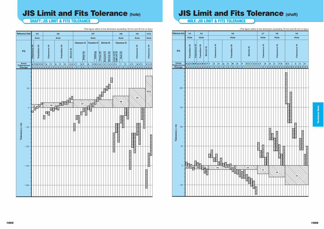
Te
ch
nic
al D
ata
Reference Axis
Fit
Hole
ToleranceRange
h4
Hole
h5
Hole
h6
Hole
h7
Hole
(The figure refers to the dimension exceeding 18 mm and 30 mm or less.)
H
5
Js
5
K
5
M
5
M
6
Js
6
K
5
M
6
N
6
P
6
H
6 7
Js
6 7
K
6 7
M
6 7
N
6 7
P
6 7
F
6
F
7 8
H
7 8
E
7
R
7
S
7
T
7
h8
Hole
h9
Hole
D
8 9
E
8 9
H
8 9
C
9 10
F
8
B
10
8
D
9
10
E
8 9
H
8 9
U
7
X
77
G
6 7
200
150
100
50
0
-50
Tra
nsit
ion
fit
Tra
nsit
ion
fit
Tra
nsit
ion
fit
Sh
rin
k f
it
Sh
rin
k f
it
Cle
aran
ce f
it
Cle
aran
ce f
it
Cle
aran
ce f
it
Cle
aran
ce f
it
Cle
aran
ce f
it
To
lera
nce (l
m)
h4 h5 h6 h6h7
h8
h9
19061905
HOLE:JIS LIMIT & FITS TOLERANCE
JIS Limit and Fits Tolerance (shaft)
SHAFT:JIS LIMIT & FITS TOLERANCE
JIS Limit and Fits Tolerance (hole)
Reference Hole
Fit
Axis
ToleranceRange
H5
Axis
H6
Axis
H7
Axis
H8
Axis
(The figure refers to the dimension exceeding 18 mm and 30 mm or less.)
g
4
h
4
js
4
k
4
m
4
n
6
p
6
f
6
g
5 6
h
6 7
js
6 7
e
7
f
6
g
6
e
8 9
f
7 8
h
7 8
d
9
k
6
m
6
n
6
p
6
r
6
s
6
t
6
H9
Axis
H10
Axis
d
8 9
g
8
e
9
h
8 9
c
9
b
9
c
9
d
9
u
6
x
67
h
5 6
js
5 6
k
5 6
m
5 6
50
0
-50
-100
-150
-200
Clearance fit Transition fit Shrink fit Clearance fit
Cle
aran
ce f
it
Cle
aran
ce f
it
Slid
e f
it
Hit
tin
g
Press f
it
Str
ong
pres
s fit
Sh
rin
k f
it
Lo
os
e r
oll
fit
Lig
ht
roll f
it
Ro
ll f
it
Cle
aran
ce f
it
Cle
aran
ce f
it
Tra
nsit
ion
fit
Tra
nsit
ion
fit
Sh
rin
k f
it
To
lera
nce (l
m)
H5 H6H7
H8
H9
H10
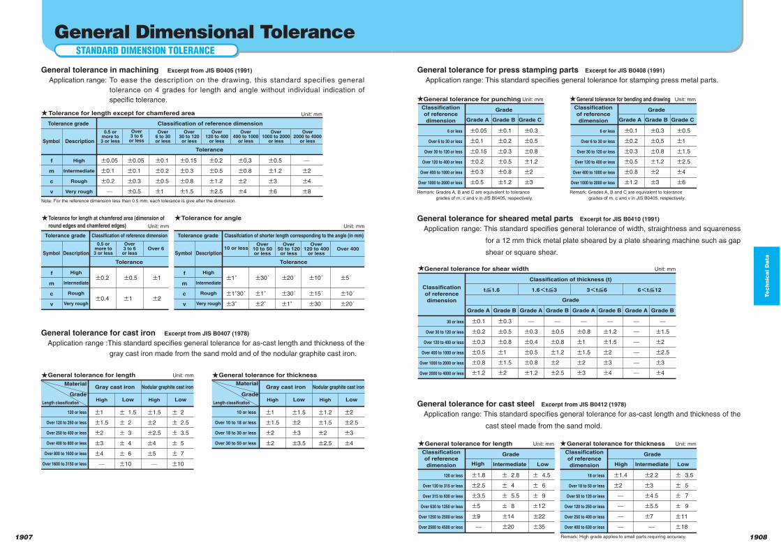
Te
ch
nic
al D
ata
19081907
±0.05
±0.1
±0.15
±0.2
±0.3
±0.5
±0.1
±0.2
±0.3
±0.5
±0.8
±1.2
±0.3
±0.5
±0.8
±1.2
±2
±3
±0.1
±0.2
±0.3
±0.5
±0.8
±1.2
±0.3
±0.5
±0.8
±1.2
±2
±3
±0.5
±1
±1.5
±2.5
±4
±6
±0.1
±0.2
±0.3
±0.5
±0.8
±1.2
±0.3
±0.5
±0.8
±1
±1.5
±2
±0.3
±0.4
±0.5
±0.8
±1.2
±0.5
±0.8
±1.2
±2
±2.5
±0.8
±1
±1.5
±2
±3
±1.2
±1.5
±2
±3
±4
±1.5
±2
±2.5
±3
±4
±1.8
±2.5
±3.5
±5
±9
± 2.8
± 4
± 5.5
± 8
±14
±20
± 4.5
± 6
± 9
±12
±22
±35
±1.4
±2
±2.2
±3
±4.5
±5.5
±7
± 3.5
± 5
± 7
± 9
±11
±18
6 or less
Over 6 to 30 or less
Over 30 to 120 or less
Over 120 to 400 or less
Over 400 to 1000 or less
Over 1000 to 2000 or less
GradeClassification
of reference
dimension Grade A Grade B Grade C
Unit: mmGeneral tolerance for punching
Remark: Grades A, B and C are equivalent to tolerance
grades of m, c and v in JIS B0405, respectively.
6 or less
Over 6 to 30 or less
Over 30 to 120 or less
Over 120 to 400 or less
Over 400 to 1000 or less
Over 1000 to 2000 or less
GradeClassification
of reference
dimension Grade A Grade B Grade C
Unit: mmGeneral tolerance for bending and drawing
Remark: Grades A, B and C are equivalent to tolerance
grades of m, c and v in JIS B0405, respectively.
30 or less
Over 30 to 120 or less
Over 120 to 400 or less
Over 400 to 1000 or less
Over 1000 to 2000 or less
Over 2000 to 4000 or less
tF1.6
Classification of thickness (t)
Classification
of reference
dimension
Grade A Grade B
1.6StF3
Grade A Grade B
3StF6
Grade A Grade B
6StF12
Grade A Grade B
Unit: mmGeneral tolerance for shear width
120 or less
Over 120 to 315 or less
Over 315 to 630 or less
Over 630 to 1250 or less
Over 1250 to 2500 or less
Over 2500 to 4500 or less
GradeClassification
of reference
dimension Intermediate Low
Unit: mmGeneral tolerance for length
18 or less
Over 18 to 50 or less
Over 50 to 120 or less
Over 120 to 250 or less
Over 250 to 400 or less
Over 400 to 630 or less
GradeClassification
of reference
dimension High Intermediate Low
Unit: mmGeneral tolerance for thickness
Remark: High grade applies to small parts requiring accuracy.
High
Grade
General tolerance for press stamping parts Excerpt for JIS B0408 (1991)
Application range: This standard specifies general tolerance for stamping press metal parts.
General tolerance for sheared metal parts Excerpt for JIS B0410 (1991)
Application range: This standard specifies general tolerance of width, straightness and squareness
for a 12 mm thick metal plate sheared by a plate shearing machine such as gap
shear or square shear.
General tolerance for cast steel Excerpt from JIS B0412 (1978)
Application range: This standard specifies general tolerance for as-cast length and thickness of the
cast steel made from the sand mold.
STANDARD DIMENSION TOLERANCE
General Dimensional Tolerance
f
m
c
v
±0.05
±0.1
±0.2
±0.05
±0.1
±0.3
±0.5
±0.1
±0.2
±0.5
±1
±0.15
±0.3
±0.8
±1.5
±0.2
±0.5
±1.2
±2.5
±0.3
±0.8
±2
±4
±0.5
±1.2
±3
±6
±2
±4
±8
Tolerance
f
m
c
v
±1°
±1°30´
±3°
±30´
±1°
±2°
±20´
±30´
±1°
±10´
±15´
±30´
±5´
±10´
±20´
Tolerance
Note: For the reference dimension less than 0.5 mm, each tolerance is give after the dimension.
f
m
c
v
±0.2
±0.4
±0.5
±1
±1
±2
Tolerance
±1
±1.5
±2
±3
±4
± 1.5
± 2
± 3
± 4
± 6
±10
±1.5
±2
±2.5
±4
±5
± 2
± 2.5
± 3.5
± 5
± 7
±10
±1
±1.5
±2
±2
±1.5
±2
±3
±3.5
±1.2
±1.5
±2
±2.5
±2
±2.5
±3
±4
Tolerance for length except for chamfered area
Tolerance grade
Symbol Description
High
Intermediate
Rough
Very rough
0.5 ormore to3 or less
Over3 to 6
or less
Over6 to 30or less
Over30 to 120or less
Over120 to 400
or less
Over400 to 1000
or less
Over1000 to 2000
or less
Over2000 to 4000
or less
Classification of reference dimension
Unit: mm
Unit: mm
Unit: mm
Tolerance for length at chamfered area (dimension of
round edges and chamfered edges)
Tolerance for angle
Tolerance grade
Symbol Description
High
Intermediate
Rough
Very rough
10 or lessOver
10 to 50or less
Over50 to 120or less
Over120 to 400
or lessOver 400
Classifciation of shorter length corresponding to the angle (in mm)Tolerance grade
Symbol Description
High
Intermediate
Rough
Very rough
0.5 ormore to3 or less
Over3 to 6
or lessOver 6
Classification of reference dimension
Material
Grade
Length classification
120 or less
Over 120 to 250 or less
Over 250 to 400 or less
Over 400 to 800 or less
Over 800 to 1600 or less
Over 1600 to 3150 or less
Gray cast iron
High Low
Nodular graphite cast iron
High Low
Unit: mmGeneral tolerance for length
Material
Grade
Length classification
10 or less
Over 10 to 18 or less
Over 18 to 30 or less
Over 30 to 50 or less
Gray cast iron
High Low
Nodular graphite cast iron
High Low
General tolerance for thickness
General tolerance in machining Excerpt from JIS B0405 (1991)
Application range: To ease the description on the drawing, this standard specifies general
tolerance on 4 grades for length and angle without individual indication of
specific tolerance.
General tolerance for cast iron Excerpt from JIS B0407 (1978)
Application range :This standard specifies general tolerance for as-cast length and thickness of the
gray cast iron made from the sand mold and of the nodular graphite cast iron.
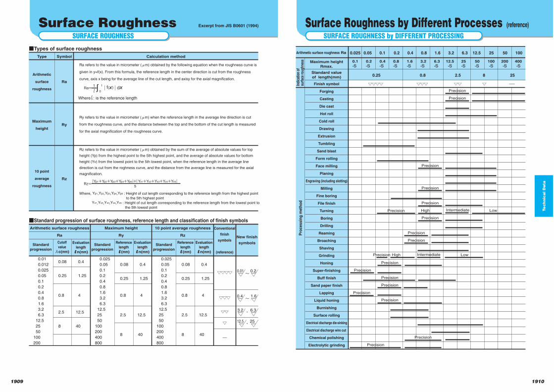
Te
ch
nic
al D
ata
19101909
SURFACE ROUGHNESS by DIFFERENT PROCESSING
Surface Roughness by Different Processes (reference)
Finish symbol
Forging
Casting
Die cast
Hot roll
Cold roll
Drawing
Extrusion
Tumbling
Sand blast
Form rolling
Face milling
Planing
Engraving (including slotting)
Milling
Fine boring
File finish
Turning
Boring
Drilling
Reaming
Broaching
Shaving
Grinding
Honing
Super-finishing
Buff finish
Sand paper finish
Lapping
Liquid honing
Burnishing
Surface rolling
Electrical discharge die-sinking
Electrical discharge wire cut
Chemical polishing
Electrolytic grinding
0.025
0.1
-S
0.05
0.2
-S
0.1
0.4
-S
0.2
0.8
-S
0.4
1.6
-S
0.8
3.2
-S
1.6
6.3
-S
3.2
12.5
-S
6.3
25
-S
12.5
50
-S
25
100
-S
50
200
-S
100
400
-S
0.25 0.8 2.5 8 25
Arithmetic surface roughness Ra
Maximum height
Rmax.
Standard value
of length(mm)
Indi
catio
n of
surf
ace
roug
hnes
sP
rocessin
g m
eth
od
▽▽▽▽ ▽▽▽ ▽▽ ▽Precision
Precision
Precision
Precision
Precision
Intermediate High Low
Precision
Precision
Precision
Precision
Intermediate High LowPrecision
Precision
Precision
Precision
Precision
Precision
Precision
Precision
Precision
SURFACE ROUGHNESS
Surface Roughness Excerpt from JIS B0601 (1994)
Whereι : is the reference length
Calculation methodType
Arithmetic
surface
roughness
Ra
Ry
Rz
Maximum
height
10 point
average
roughness
Symbol
qTypes of surface roughness
qStandard progression of surface roughness, reference length and classification of finish symbols
Ra= ∫0
1|f(χ)|dχ1ι
Rz=|Yp1+Yp2+Yp3+Yp4+Yp5|+|Yv1+Yv2+Yv3+Yv4+Yv5|
5
0.01
0.012
0.025
0.05
0.1
0.2
0.4
0.8
1.6
3.2
6.3
12.5
25
50
100
200
0.08
0.25
0.8
2.5
8
Arithmetic surface roughness
Ra
Conventional
finish
symbols
(reference)
New finish
symbols
0.4
1.25
4
12.5
40
0.025
0.05
0.1
0.2
0.4
0.8
1.6
3.2
6.3
12.5
25
50
100
200
400
800
0.08
0.25
0.8
2.5
8
Maximum height
Ry
0.4
1.25
4
12.5
40
0.025
0.05
0.1
0.2
0.4
0.8
1.6
3.2
6.3
12.5
25
50
100
200
400
800
0.08
0.25
0.8
2.5
8
0.4
1.25
4
12.5
40
▽▽▽▽
▽▽▽
▽▽
▽
10 point average roughness
Rz
0.01 0.2
0.4 1.6
3.2 6.3
12.5 25
~
~
・
・
Ra refers to the value in micrometer (lm) obtained by the following equation when the roughness curve is
given in y=f(x). From this formula, the reference length in the center direction is cut from the roughness
curve, axis x being for the average line of the cut length, and axisy for the axial magnification.
Ry refers to the value in micrometer (lm) when the reference length in the average line direction is cut
from the roughness curve, and the distance between the top and the bottom of the cut length is measured
for the axial magnification of the roughness curve.
Where, Yp1,Yp2,Yp3,Yp4,Yp5 : Height of cut length corresponding to the reference length from the highest point
to the 5th highest pointYv1,Yv2,Yv3,Yv4,Yv5 : Height of cut length corresponding to the reference length from the lowest point to
the 5th lowest point
Rz refers to the value in micrometer (lm) obtained by the sum of the average of absolute values for top
height (Yp) from the highest point to the 5th highest point, and the average of absolute values for bottom
height (Yv) from the lowest point to the 5th lowest point, when the reference length in the average line
direction is cut from the roghness curve, and the distance from the average line is measured for the axial
magnification.
Standard
progression
Cutoff
value
λc(mm)
Evaluation
length
Jn(mm)
Standard
progression
Reference
length
J(mm)
Evaluation
length
Jn(mm)
Standard
progression
Reference
length
J(mm)
Evaluation
length
Jn(mm)
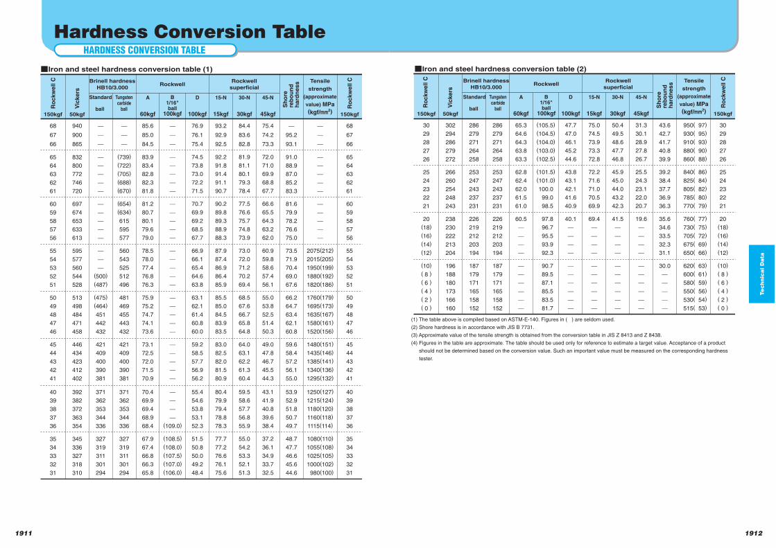
Te
ch
nic
al D
ata
19121911
150kgf 150kgf50kgf
A
60kgf
D
100kgf
15-N
15kgf
30-N
30kgf
30
29
28
27
26
302
294
286
279
272
286
279
271
264
258
286
279
271
264
258
30
29
28
27
26
43.6
42.7
41.7
40.8
39.9
950( 97)
930( 95)
910( 93)
880( 90)
860( 88)
65.3
64.6
64.3
63.8
63.3
(105.5)
(104.5)
(104.0)
(103.0)
(102.5)
47.7
47.0
46.1
45.2
44.6
75.0
74.5
73.9
73.3
72.8
50.4
49.5
48.6
47.7
46.8
31.3
30.1
28.9
27.8
26.7
25
24
23
22
21
266
260
254
248
243
253
247
243
237
231
253
247
243
237
231
25
24
23
22
21
39.2
38.4
37.7
36.9
36.3
840( 86)
825( 84)
805( 82)
785( 80)
770( 79)
62.8
62.4
62.0
61.5
61.0
(101.5)
(101.0)
100.0
99.0
98.5
43.8
43.1
42.1
41.6
40.9
72.2
71.6
71.0
70.5
69.9
45.9
45.0
44.0
43.2
42.3
25.5
24.3
23.1
22.0
20.7
20
(18)
(16)
(14)
(12)
238
230
222
213
204
226
219
212
203
194
226
219
212
203
194
20
(18)
(16)
(14)
(12)
35.6
34.6
33.5
32.3
31.1
760( 77)
730( 75)
705( 72)
675( 69)
650( 66)
60.5
97.8
96.7
95.5
93.9
92.3
40.1
69.4
41.5
19.6
(10)
( 8 )
( 6 )
( 4 )
( 2 )
( 0 )
196
188
180
173
166
160
187
179
171
165
158
152
187
179
171
165
158
152
(10)
( 8 )
( 6 )
( 4 )
( 2 )
( 0 )
30.0
620( 63)
600( 61)
580( 59)
550( 56)
530( 54)
515( 53)
90.7
89.5
87.1
85.5
83.5
81.7
45-N
45kgf
(1) The table above is compiled based on ASTM-E-140. Figures in ( ) are seldom used.
(2) Shore hardness is in accordance with JIS B 7731.
(3) Approximate value of the tensile strength is obtained from the conversion table in JIS Z 8413 and Z 8438.
(4) Figures in the table are approximate. The table should be used only for reference to estimate a target value. Acceptance of a product
should not be determined based on the conversion value. Such an important value must be measured on the corresponding hardness
tester.
qIron and steel hardness conversion table (2)
Brinell hardness
HB10/3.000Rockwell
Rockwell
superficial
Tensile
strength
(approximate
value) MPa
(kgf/mm2)
Ro
ck
we
ll C
Ro
ck
we
ll C
Vic
ke
rs
Sh
ore
reb
ou
nd
ha
rdn
es
s
Standard
ball
Tungstencarbide
ball
B1/16"ball
100kgf
HARDNESS CONVERSION TABLE
Hardness Conversion Table
68
67
66
940
900
865
150kgf
68
67
66
150kgf
95.2
93.1
50kgf
85.6
85.0
84.5
A
60kgf
76.9
76.1
75.4
D
100kgf
93.2
92.9
92.5
15-N
15kgf
84.4
83.6
82.8
30-N
30kgf
75.4
74.2
73.3
65
64
63
62
61
832
800
772
746
720
(739)
(722)
(705)
(688)
(670)
65
64
63
62
61
91.0
88.9
87.0
85.2
83.3
83.9
83.4
82.8
82.3
81.8
74.5
73.8
73.0
72.2
71.5
92.2
91.8
91.4
91.1
90.7
81.9
81.1
80.1
79.3
78.4
72.0
71.0
69.9
68.8
67.7
60
59
58
57
56
697
674
653
633
613
(654)
(634)
615
595
577
60
59
58
57
56
81.6
79.9
78.2
76.6
75.0
81.2
80.7
80.1
79.6
79.0
70.7
69.9
69.2
68.5
67.7
90.2
89.8
89.3
88.9
88.3
77.5
76.6
75.7
74.8
73.9
66.6
65.5
64.3
63.2
62.0
55
54
53
52
51
595
577
560
544
528
(500)
(487)
560
543
525
512
496
55
54
53
52
51
73.5
71.9
70.4
69.0
67.6
2075(212)
2015(205)
1950(199)
1880(192)
1820(186)
78.5
78.0
77.4
76.8
76.3
66.9
66.1
65.4
64.6
63.8
87.9
87.4
86.9
86.4
85.9
73.0
72.0
71.2
70.2
69.4
60.9
59.8
58.6
57.4
56.1
50
49
48
47
46
513
498
484
471
458
(475)
(464)
451
442
432
481
469
455
443
432
50
49
48
47
46
66.2
64.7
63.4
62.1
60.8
1760(179)
1695(173)
1635(167)
1580(161)
1520(156)
75.9
75.2
74.7
74.1
73.6
63.1
62.1
61.4
60.8
60.0
85.5
85.0
84.5
83.9
83.5
68.5
67.6
66.7
65.8
64.8
55.0
53.8
52.5
51.4
50.3
45
44
43
42
41
446
434
423
412
402
421
409
400
390
381
421
409
400
390
381
45
44
43
42
41
59.6
58.4
57.2
56.1
55.0
1480(151)
1435(146)
1385(141)
1340(136)
1295(132)
73.1
72.5
72.0
71.5
70.9
59.2
58.5
57.7
56.9
56.2
83.0
82.5
82.0
81.5
80.9
64.0
63.1
62.2
61.3
60.4
49.0
47.8
46.7
45.5
44.3
40
39
38
37
36
392
382
372
363
354
371
362
353
344
336
371
362
353
344
336
40
39
38
37
36
53.9
52.9
51.8
50.7
49.7
1250(127)
1215(124)
1180(120)
1160(118)
1115(114)
70.4
69.9
69.4
68.9
68.4
(109.0)
55.4
54.6
53.8
53.1
52.3
80.4
79.9
79.4
78.8
78.3
59.5
58.6
57.7
56.8
55.9
43.1
41.9
40.8
39.6
38.4
35
34
33
32
31
345
336
327
318
310
327
319
311
301
294
327
319
311
301
294
35
34
33
32
31
48.7
47.7
46.6
45.6
44.6
1080(110)
1055(108)
1025(105)
1000(102)
980(100)
67.9
67.4
66.8
66.3
65.8
(108.5)
(108.0)
(107.5)
(107.0)
(106.0)
51.5
50.8
50.0
49.2
48.4
77.7
77.2
76.6
76.1
75.6
55.0
54.2
53.3
52.1
51.3
37.2
36.1
34.9
33.7
32.5
45-N
45kgf
qIron and steel hardness conversion table (1)
Brinell hardness
HB10/3.000Rockwell
Rockwell
superficial
Tensile
strength
(approximate
value) MPa
(kgf/mm2)
Ro
ck
we
ll C
Ro
ck
we
ll C
Vic
ke
rs
Sh
ore
reb
ou
nd
ha
rdn
es
s
Standard
ball
Tungstencarbide
ball
B1/16"ball
100kgf
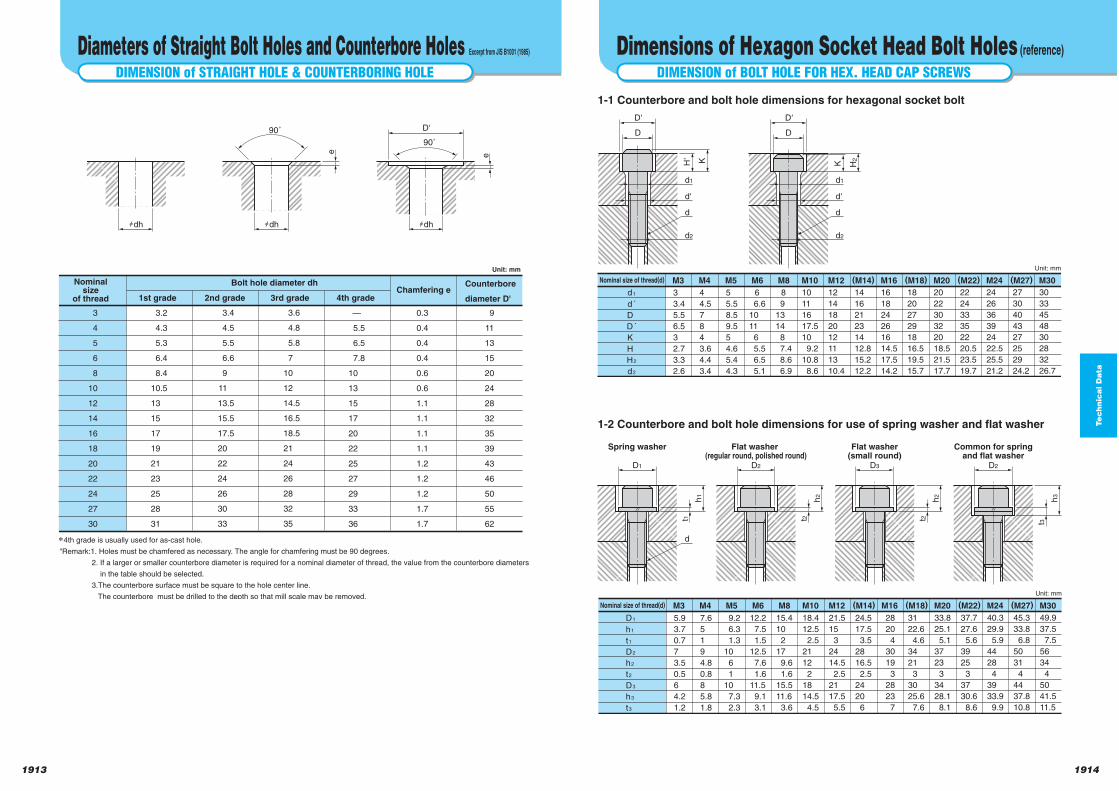
Te
ch
nic
al D
ata
19141913
DIMENSION of BOLT HOLE FOR HEX. HEAD CAP SCREWS
Dimensions of Hexagon Socket Head Bolt Holes (reference)
d1
d'
d2
D'
D
H' K
d1
d'
d2
D'
D
K H2
d d
3
3.4
5.5
6.5
3
2.7
3.3
2.6
4
4.5
7
8
4
3.6
4.4
3.4
5
5.5
8.5
9.5
5
4.6
5.4
4.3
6 6.6
10
11
6
5.5
6.5
5.1
8 9
13
14
8
7.4
8.6
6.9
10
11
16
17.5
10
9.2
10.8
8.6
12
14
18
20
12
11
13
10.4
14
16
21
23
14
12.8
15.2
12.2
16
18
24
26
16
14.5
17.5
14.2
18
20
27
29
18
16.5
19.5
15.7
20
22
30
32
20
18.5
21.5
17.7
22
24
33
35
22
20.5
23.5
19.7
24
26
36
39
24
22.5
25.5
21.2
27
30
40
43
27
25
29
24.2
30
33
45
48
30
28
32
26.7
d1
d´
D
D´
K
H
H2
d2
Nominal size of thread(d) M3 M4 M5 M6 M8 M10 M12 (M14) (M18) (M22) (M27)M16 M20 M24 M30
Unit: mm
D1
Spring washer
t1
h1
d
D2
Flat washer (regular round, polished round)
t2
h2
D3
Flat washer(small round)
t2
h2
D2
Common for springand flat washer
t3
h3
5.9
3.7
0.7
7
3.5
0.5
6
4.2
1.2
7.6
5
1
9
4.8
0.8
8
5.8
1.8
9.2
6.3
1.3
10
6
1
10
7.3
2.3
12.2
7.5
1.5
12.5
7.6
1.6
11.5
9.1
3.1
15.4
10
2
17
9.6
1.6
15.5
11.6
3.6
18.4
12.5
2.5
21
12
2
18
14.5
4.5
21.5
15
3
24
14.5
2.5
21
17.5
5.5
24.5
17.5
3.5
28
16.5
2.5
24
20
6
31
22.6
4.6
34
21
3
30
25.6
7.6
28
20
4
30
19
3
28
23
7
33.8
25.1
5.1
37
23
3
34
28.1
8.1
37.7
27.6
5.6
39
25
3
37
30.6
8.6
40.3
29.9
5.9
44
28
4
39
33.9
9.9
45.3
33.8
6.8
50
31
4
44
37.8
10.8
49.9
37.5
7.5
56
34
4
50
41.5
11.5
D1
h1
t1
D2
h2
t2
D3
h3
t3
Nominal size of thread(d) M3 M4 M5 M6 M8 M10 M12 (M14) (M18) (M22) (M27)M16 M20 M24 M30
Unit: mm
1-1 Counterbore and bolt hole dimensions for hexagonal socket bolt
1-2 Counterbore and bolt hole dimensions for use of spring washer and flat washer
DIMENSION of STRAIGHT HOLE & COUNTERBORING HOLE
Diameters of Straight Bolt Holes and Counterbore Holes Excerpt from JIS B1001 (1985)
90˚
90˚
hdh hdh
e
hdh
e
D'
3
4
5
6
8
10
12
14
16
18
20
22
24
27
30
3.2
4.3
5.3
6.4
8.4
10.5
13
15
17
19
21
23
25
28
31
3.4
4.5
5.5
6.6
9
11
13.5
15.5
17.5
20
22
24
26
30
33
3.6
4.8
5.8
7
10
12
14.5
16.5
18.5
21
24
26
28
32
35
—
5.5
6.5
7.8
10
13
15
17
20
22
25
27
29
33
36
0.3
0.4
0.4
0.4
0.6
0.6
1.1
1.1
1.1
1.1
1.2
1.2
1.2
1.7
1.7
9
11
13
15
20
24
28
32
35
39
43
46
50
55
62
4th grade is usually used for as-cast hole.
"Remark:1. Holes must be chamfered as necessary. The angle for chamfering must be 90 degrees.
2. If a larger or smaller counterbore diameter is required for a nominal diameter of thread, the value from the counterbore diameters
in the table should be selected.
3.The counterbore surface must be square to the hole center line.
The counterbore must be drilled to the depth so that mill scale may be removed.
Nominalsize
of thread 1st grade 2nd grade 3rd grade 4th grade
Bolt hole diameter dhChamfering e
Counterbore
diameter D'
Unit: mm
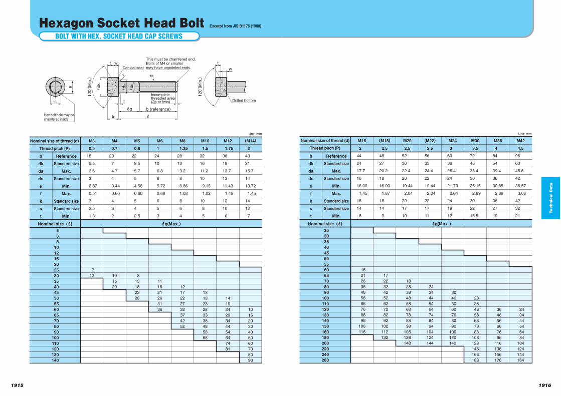
Te
ch
nic
al D
ata
19161915
2
44
24
17.7
16
16.00
1.45
16
14
8
16
21
26
36
46
56
66
76
86
96
106
116
17
22
32
42
52
62
72
82
92
102
112
132
18
28
38
48
58
68
78
88
98
108
128
148
24
34
44
54
64
74
84
94
104
124
144
30
40
50
60
70
80
90
100
120
140
28
38
48
58
68
78
88
108
128
148
168
188
36
46
56
66
76
96
116
136
156
176
24
34
44
54
64
84
104
124
144
164
b
dk
da
ds
e
f
k
s
t
Reference
Standard size
Max.
Standard size
Min.
Max.
Standard size
Standard size
Min.
Nominal size (J)
25
30
35
40
45
50
55
60
65
70
80
90
100
110
120
130
140
150
160
180
200
220
240
260
Jg(Max.)
M16
2.5
48
27
20.2
18
16.00
1.87
18
14
9
(M18)
2.5
52
30
22.4
20
19.44
2.04
20
17
10
M20
2.5
56
33
24.4
22
19.44
2.04
22
17
11
(M22)
3
60
36
26.4
24
21.73
2.04
24
19
12
M24
3.5
72
45
33.4
30
25.15
2.89
30
22
15.5
M30
4
84
54
39.4
36
30.85
2.89
36
27
19
M36
4.5
96
63
45.6
42
36.57
3.06
42
32
21
M42Nominal size of thread (d)
Thread pitch (P)
Unit: mm
BOLT WITH HEX. SOCKET HEAD CAP SCREWS
Hexagon Socket Head Bolt Excerpt from JIS B1176 (1988)
e
s f
Incompletethreaded area(2p or less)
k j
jg b (reference)
Hex bolt hole may bechamfered inside
t
hd
k
hd
a
hd
s
12
0˚(
Min
.)
w
r d
Conical seat
t
12
0˚(
Min
.)
w
Drilled bottom
This must be chamfered end.Bolts of M4 or smallermay have unpointed ends.
0.5
18
5.5
3.6
3
2.87
0.51
3
2.5
1.3
7
12 10
15
20
8
13
18
23
28
11
16
21
26
31
36
12
17
22
27
32
37
42
52
13
18
23
28
33
38
48
58
68
14
19
24
29
34
44
54
64
74
81
10
15
20
30
40
50
60
70
80
90
b
dk
da
ds
e
f
k
s
t
Reference
Standard size
Max.
Standard size
Min.
Max.
Standard size
Standard size
Min.
Nominal size of thread (d)
Thread pitch (P)
Nominal size (J)
5
6
8
10
12
16
20
25
30
35
40
45
50
55
60
65
70
80
90
100
110
120
130
140
Jg(Max.)
M3
0.7
20
7
4.7
4
3.44
0.60
4
3
2
M4
0.8
22
8.5
5.7
5
4.58
0.60
5
4
2.5
M5
1
24
10
6.8
6
5.72
0.68
6
5
3
M6
1.25
28
13
9.2
8
6.86
1.02
8
6
4
M8
1.5
32
16
11.2
10
9.15
1.02
10
8
5
M10
1.75
36
18
13.7
12
11.43
1.45
12
10
6
M12
2
40
21
15.7
14
13.72
1.45
14
12
7
(M14)
Unit: mm
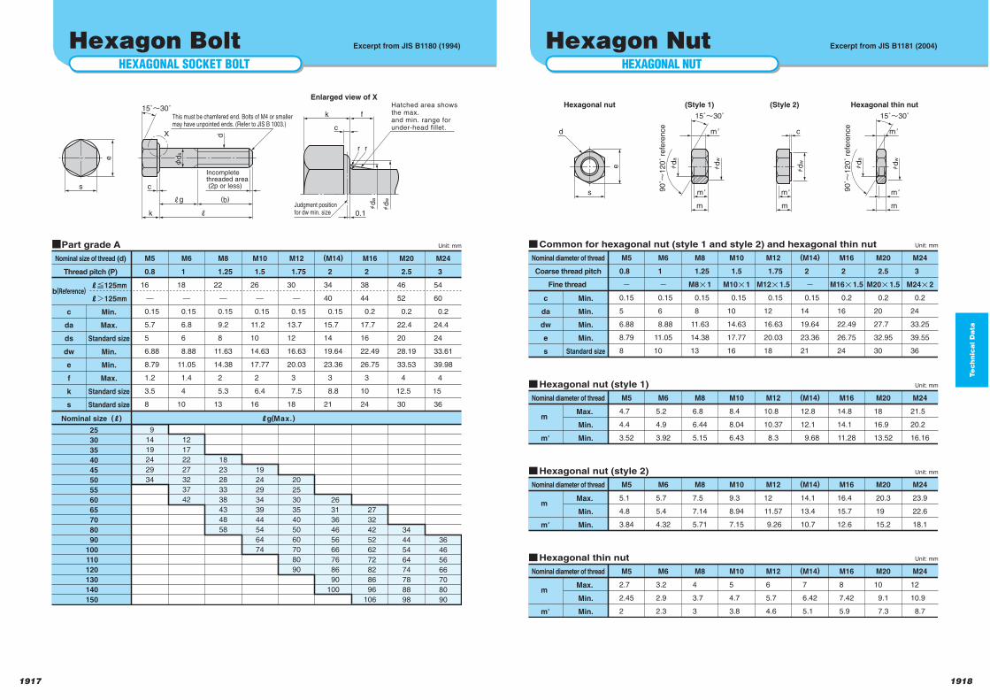
Te
ch
nic
al D
ata
19181917
HEXAGONAL NUT
Hexagon Nut Excerpt from JIS B1181 (2004)
e
s m'
m
d
hd
a
m'
hd
w
90˚n
12
0˚
refe
ren
ce
15˚n30˚
Hexagonal nut (Style 1)
m'
m
hd
a
m'
hd
w
90˚n
12
0˚
refe
ren
ce
15˚n30˚
Hexagonal thin nut
m'
m
c
hd
w
(Style 2)
0.8
o
0.15
5
6.88
8.79
8
c
da
dw
e
s
Min.
Min.
Min.
Min.
Standard size
Nominal diameter of thread
Coarse thread pitch
Fine thread
M5
1
o
0.15
6
8.88
11.05
10
M6
1.25
M8p1
0.15
8
11.63
14.38
13
M8
1.5
M10p1
0.15
10
14.63
17.77
16
M10
1.75
M12p1.5
0.15
12
16.63
20.03
18
M12
2
o
0.15
14
19.64
23.36
21
(M14)
2
M16p1.5
0.2
16
22.49
26.75
24
M16
2.5
M20p1.5
0.2
20
27.7
32.95
30
M20
3
M24p2
0.2
24
33.25
39.55
36
M24
Unit: mmqCommon for hexagonal nut (style 1 and style 2) and hexagonal thin nut
4.7
4.4
3.52
m
m'
Max.
Min.
Min.
Nominal diameter of thread M5
5.2
4.9
3.92
M6
6.8
6.44
5.15
M8
8.4
8.04
6.43
M10
10.8
10.37
8.3
M12
12.8
12.1
9.68
(M14)
14.8
14.1
11.28
M16
18
16.9
13.52
M20
21.5
20.2
16.16
M24
Unit: mmqHexagonal nut (style 1)
5.1
4.8
3.84
m
m'
Max.
Min.
Min.
Nominal diameter of thread M5
5.7
5.4
4.32
M6
7.5
7.14
5.71
M8
9.3
8.94
7.15
M10
12
11.57
9.26
M12
14.1
13.4
10.7
(M14)
16.4
15.7
12.6
M16
20.3
19
15.2
M20
23.9
22.6
18.1
M24
Unit: mmqHexagonal nut (style 2)
2.7
2.45
2
m
m'
Max.
Min.
Min.
Nominal diameter of thread M5
3.2
2.9
2.3
M6
4
3.7
3
M8
5
4.7
3.8
M10
6
5.7
4.6
M12
7
6.42
5.1
(M14)
8
7.42
5.9
M16
10
9.1
7.3
M20
12
10.9
8.7
M24
Unit: mmqHexagonal thin nut
HEXAGONAL SOCKET BOLT
Hexagon Bolt Excerpt from JIS B1180 (1994)
e
s c
X
Incompletethreaded area (2p or less)
k 0.1
k f
j
jg (b)
φd
s
d
This must be chamfered end. Bolts of M4 or smaller may have unpointed ends. (Refer to JIS B 1003.)
Judgment positionfor dw min. size
Hatched area showsthe max.and min. range forunder-head fillet.
15˚n30˚
Enlarged view of X
c
hd
a
hd
w
r r
0.8
16
0.15
5.7
5
6.88
8.79
1.2
3.5
8
9
14
19
24
29
34
12
17
22
27
32
37
42
18
23
28
33
38
43
48
58
19
24
29
34
39
44
54
64
74
20
25
30
35
40
50
60
70
80
90
26
31
36
46
56
66
76
86
90
100
27
32
42
52
62
72
82
86
96
106
34
44
54
64
74
78
88
98
b(Reference)
c
da
ds
dw
e
f
k
s
Jf125mm
Jd125mm
Min.
Max.
Standard size
Min.
Min.
Max.
Standard size
Standard size
Nominal size of thread (d)
Thread pitch (P)
Nominal size (J)
25
30
35
40
45
50
55
60
65
70
80
90
100
110
120
130
140
150
Jg(Max.)
M5
1
18
0.15
6.8
6
8.88
11.05
1.4
4
10
M6
1.25
22
0.15
9.2
8
11.63
14.38
2
5.3
13
M8
1.5
26
0.15
11.2
10
14.63
17.77
2
6.4
16
M10
1.75
30
0.15
13.7
12
16.63
20.03
3
7.5
18
M12
2
34
40
0.15
15.7
14
19.64
23.36
3
8.8
21
(M14)
2
38
44
0.2
17.7
16
22.49
26.75
3
10
24
M16
2.5
46
52
0.2
22.4
20
28.19
33.53
4
12.5
30
M20
36
46
56
66
70
80
90
3
54
60
0.2
24.4
24
33.61
39.98
4
15
36
M24
Unit: mmqPart grade A
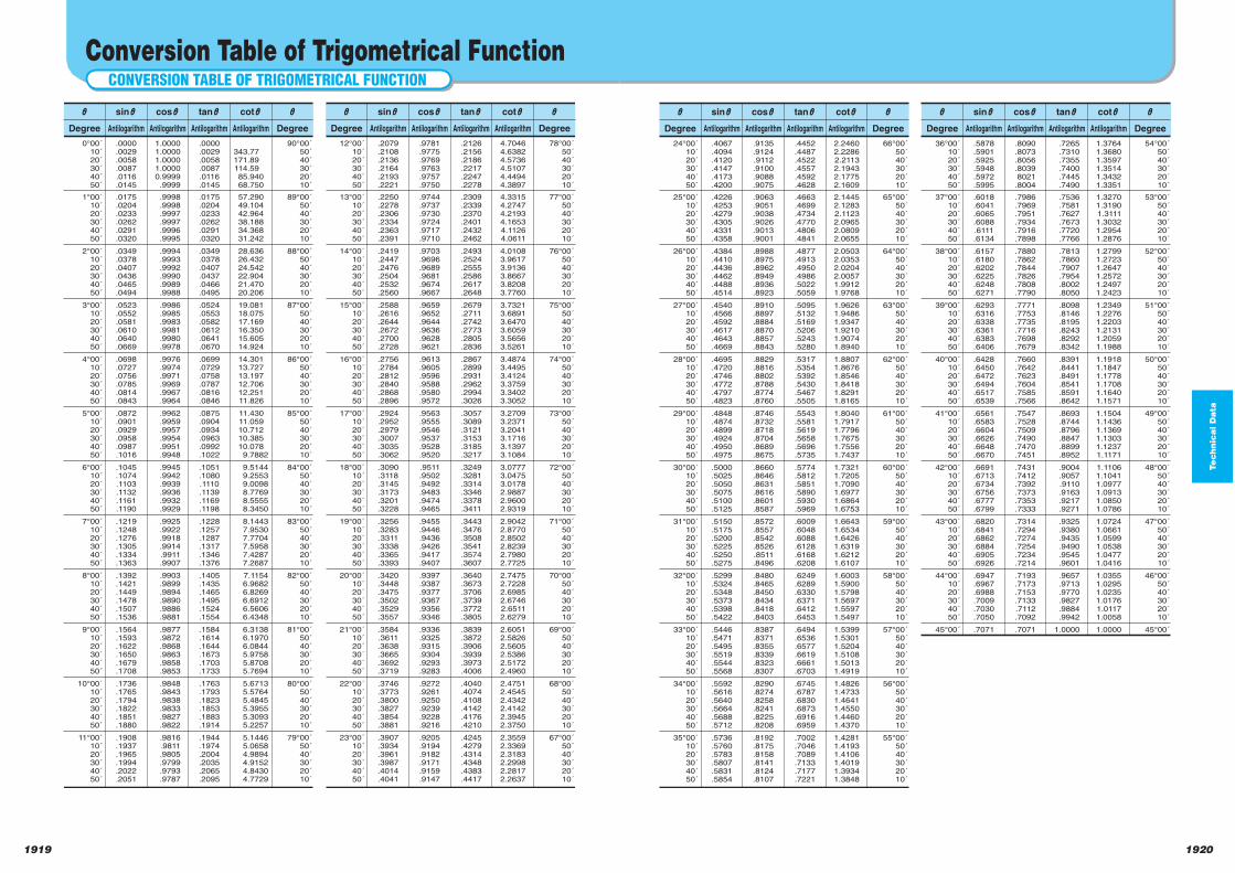
Te
ch
nic
al D
ata
19201919
K
Degree
24°00´
10´
20´
30´
40´
50´
66°00´
50´
40´
30´
20´
10´
sinK
Antilogarithm
.4067
.4094
.4120
.4147
.4173
.4200
cosK
Antilogarithm
.9135
.9124
.9112
.9100
.9088
.9075
tanK
Antilogarithm
.4452
.4487
.4522
.4557
.4592
.4628
2.2460
2.2286
2.2113
2.1943
2.1775
2.1609
25°00´
10´
20´
30´
40´
50´
65°00´
50´
40´
30´
20´
10´
.4226
.4253
.4279
.4305
.4331
.4358
.9063
.9051
.9038
.9026
.9013
.9001
.4663
.4699
.4734
.4770
.4806
.4841
2.1445
2.1283
2.1123
2.0965
2.0809
2.0655
26°00´
10´
20´
30´
40´
50´
64°00´
50´
40´
30´
20´
10´
.4384
.4410
.4436
.4462
.4488
.4514
.8988
.8975
.8962
.8949
.8936
.8923
.4877
.4913
.4950
.4986
.5022
.5059
2.0503
2.0353
2.0204
2.0057
1.9912
1.9768
27°00´
10´
20´
30´
40´
50´
63°00´
50´
40´
30´
20´
10´
.4540
.4566
.4592
.4617
.4643
.4669
.8910
.8897
.8884
.8870
.8857
.8843
.5095
.5132
.5169
.5206
.5243
.5280
1.9626
1.9486
1.9347
1.9210
1.9074
1.8940
28°00´
10´
20´
30´
40´
50´
62°00´
50´
40´
30´
20´
10´
.4695
.4720
.4746
.4772
.4797
.4823
.8829
.8816
.8802
.8788
.8774
.8760
.5317
.5354
.5392
.5430
.5467
.5505
1.8807
1.8676
1.8546
1.8418
1.8291
1.8165
29°00´
10´
20´
30´
40´
50´
61°00´
50´
40´
30´
20´
10´
.4848
.4874
.4899
.4924
.4950
.4975
.8746
.8732
.8718
.8704
.8689
.8675
.5543
.5581
.5619
.5658
.5696
.5735
1.8040
1.7917
1.7796
1.7675
1.7556
1.7437
30°00´
10´
20´
30´
40´
50´
60°00´
50´
40´
30´
20´
10´
.5000
.5025
.5050
.5075
.5100
.5125
.8660
.8646
.8631
.8616
.8601
.8587
.5774
.5812
.5851
.5890
.5930
.5969
1.7321
1.7205
1.7090
1.6977
1.6864
1.6753
31°00´
10´
20´
30´
40´
50´
59°00´
50´
40´
30´
20´
10´
.5150
.5175
.5200
.5225
.5250
.5275
.8572
.8557
.8542
.8526
.8511
.8496
.6009
.6048
.6088
.6128
.6168
.6208
1.6643
1.6534
1.6426
1.6319
1.6212
1.6107
32°00´
10´
20´
30´
40´
50´
58°00´
50´
40´
30´
20´
10´
.5299
.5324
.5348
.5373
.5398
.5422
.8480
.8465
.8450
.8434
.8418
.8403
.6249
.6289
.6330
.6371
.6412
.6453
1.6003
1.5900
1.5798
1.5697
1.5597
1.5497
33°00´
10´
20´
30´
40´
50´
57°00´
50´
40´
30´
20´
10´
.5446
.5471
.5495
.5519
.5544
.5568
.8387
.8371
.8355
.8339
.8323
.8307
.6494
.6536
.6577
.6619
.6661
.6703
1.5399
1.5301
1.5204
1.5108
1.5013
1.4919
34°00´
10´
20´
30´
40´
50´
56°00´
50´
40´
30´
20´
10´
.5592
.5616
.5640
.5664
.5688
.5712
.8290
.8274
.8258
.8241
.8225
.8208
.6745
.6787
.6830
.6873
.6916
.6959
1.4826
1.4733
1.4641
1.4550
1.4460
1.4370
35°00´
10´
20´
30´
40´
50´
55°00´
50´
40´
30´
20´
10´
.5736
.5760
.5783
.5807
.5831
.5854
.8192
.8175
.8158
.8141
.8124
.8107
.7002
.7046
.7089
.7133
.7177
.7221
1.4281
1.4193
1.4106
1.4019
1.3934
1.3848
cotK
Antilogarithm
K
Degree
K
Degree
36°00´
10´
20´
30´
40´
50´
54°00´
50´
40´
30´
20´
10´
sinK
Antilogarithm
.5878
.5901
.5925
.5948
.5972
.5995
cosK
Antilogarithm
.8090
.8073
.8056
.8039
8021
.8004
tanK
Antilogarithm
.7265
.7310
.7355
.7400
.7445
.7490
1.3764
1.3680
1.3597
1.3514
1.3432
1.3351
37°00´
10´
20´
30´
40´
50´
53°00´
50´
40´
30´
20´
10´
.6018
.6041
.6065
.6088
.6111
.6134
.7986
.7969
.7951
.7934
.7916
.7898
.7536
.7581
.7627
.7673
.7720
.7766
1.3270
1.3190
1.3111
1.3032
1.2954
1.2876
38°00´
10´
20´
30´
40´
50´
52°00´
50´
40´
30´
20´
10´
.6157
.6180
.6202
.6225
.6248
.6271
.7880
.7862
.7844
.7826
.7808
.7790
.7813
.7860
.7907
.7954
.8002
.8050
1.2799
1.2723
1.2647
1.2572
1.2497
1.2423
39°00´
10´
20´
30´
40´
50´
51°00´
50´
40´
30´
20´
10´
.6293
.6316
.6338
.6361
.6383
.6406
.7771
.7753
.7735
.7716
.7698
.7679
.8098
.8146
.8195
.8243
.8292
.8342
1.2349
1.2276
1.2203
1.2131
1.2059
1.1988
40°00´
10´
20´
30´
40´
50´
50°00´
50´
40´
30´
20´
10´
.6428
.6450
.6472
.6494
.6517
.6539
.7660
.7642
.7623
.7604
.7585
.7566
.8391
.8441
.8491
.8541
.8591
.8642
1.1918
1.1847
1.1778
1.1708
1.1640
1.1571
41°00´
10´
20´
30´
40´
50´
49°00´
50´
40´
30´
20´
10´
.6561
.6583
.6604
.6626
.6648
.6670
.7547
.7528
.7509
.7490
.7470
.7451
.8693
.8744
.8796
.8847
.8899
.8952
1.1504
1.1436
1.1369
1.1303
1.1237
1.1171
42°00´
10´
20´
30´
40´
50´
48°00´
50´
40´
30´
20´
10´
.6691
.6713
.6734
.6756
.6777
.6799
.7431
.7412
.7392
.7373
.7353
.7333
.9004
.9057
.9110
.9163
.9217
.9271
1.1106
1.1041
1.0977
1.0913
1.0850
1.0786
43°00´
10´
20´
30´
40´
50´
47°00´
50´
40´
30´
20´
10´
.6820
.6841
.6862
.6884
.6905
.6926
.7314
.7294
.7274
.7254
.7234
.7214
.9325
.9380
.9435
.9490
.9545
.9601
1.0724
1.0661
1.0599
1.0538
1.0477
1.0416
44°00´
10´
20´
30´
40´
50´
46°00´
50´
40´
30´
20´
10´
.6947
.6967
.6988
.7009
.7030
.7050
.7193
.7173
.7153
.7133
.7112
.7092
.9657
.9713
.9770
.9827
.9884
.9942
1.0355
1.0295
1.0235
1.0176
1.0117
1.0058
45°00´ 45°00´.7071 .7071 1.0000 1.0000
cotK
Antilogarithm
K
Degree
CONVERSION TABLE OF TRIGOMETRICAL FUNCTION
Conversion Table of Trigometrical Function
K
Degree
0°00´
10´
20´
30´
40´
50´
90°00´
50´
40´
30´
20´
10´
sinK
Antilogarithm
.0000
.0029
.0058
.0087
.0116
.0145
cosK
Antilogarithm
1.0000
1.0000
1.0000
1.0000
0.9999
.9999
tanK
Antilogarithm
.0000
.0029
.0058
.0087
.0116
.0145
343.77
171.89
114.59
85.940
68.750
1°00´
10´
20´
30´
40´
50´
89°00´
50´
40´
30´
20´
10´
.0175
.0204
.0233
.0262
.0291
.0320
.9998
.9998
.9997
.9997
.9996
.9995
.0175
.0204
.0233
.0262
.0291
.0320
57.290
49.104
42.964
38.188
34.368
31.242
2°00´
10´
20´
30´
40´
50´
88°00´
50´
40´
30´
20´
10´
.0349
.0378
.0407
.0436
.0465
.0494
.9994
.9993
.9992
.9990
.9989
.9988
.0349
.0378
.0407
.0437
.0466
.0495
28.636
26.432
24.542
22.904
21.470
20.206
3°00´
10´
20´
30´
40´
50´
87°00´
50´
40´
30´
20´
10´
.0523
.0552
.0581
.0610
.0640
.0669
.9986
.9985
.9983
.9981
.9980
.9978
.0524
.0553
.0582
.0612
.0641
.0670
19.081
18.075
17.169
16.350
15.605
14.924
4°00´
10´
20´
30´
40´
50´
86°00´
50´
40´
30´
20´
10´
.0698
.0727
.0756
.0785
.0814
.0843
.9976
.9974
.9971
.9969
.9967
.9964
.0699
.0729
.0758
.0787
.0816
.0846
14.301
13.727
13.197
12.706
12.251
11.826
5°00´
10´
20´
30´
40´
50´
85°00´
50´
40´
30´
20´
10´
.0872
.0901
.0929
.0958
.0987
.1016
.9962
.9959
.9957
.9954
.9951
.9948
.0875
.0904
.0934
.0963
.0992
.1022
11.430
11.059
10.712
10.385
10.078
9.7882
6°00´
10´
20´
30´
40´
50´
84°00´
50´
40´
30´
20´
10´
.1045
.1074
.1103
.1132
.1161
.1190
.9945
.9942
.9939
.9936
.9932
.9929
.1051
.1080
.1110
.1139
.1169
.1198
9.5144
9.2553
9.0098
8.7769
8.5555
8.3450
7°00´
10´
20´
30´
40´
50´
83°00´
50´
40´
30´
20´
10´
.1219
.1248
.1276
.1305
.1334
.1363
.9925
.9922
.9918
.9914
.9911
.9907
.1228
.1257
.1287
.1317
.1346
.1376
8.1443
7.9530
7.7704
7.5958
7.4287
7.2687
8°00´
10´
20´
30´
40´
50´
82°00´
50´
40´
30´
20´
10´
.1392
.1421
.1449
.1478
.1507
.1536
.9903
.9899
.9894
.9890
.9886
.9881
.1405
.1435
.1465
.1495
.1524
.1554
7.1154
6.9682
6.8269
6.6912
6.5606
6.4348
9°00´
10´
20´
30´
40´
50´
81°00´
50´
40´
30´
20´
10´
.1564
.1593
.1622
.1650
.1679
.1708
.9877
.9872
.9868
.9863
.9858
.9853
.1584
.1614
.1644
.1673
.1703
.1733
6.3138
6.1970
6.0844
5.9758
5.8708
5.7694
10°00´
10´
20´
30´
40´
50´
80°00´
50´
40´
30´
20´
10´
.1736
.1765
.1794
.1822
.1851
.1880
.9848
.9843
.9838
.9833
.9827
.9822
.1763
.1793
.1823
.1853
.1883
.1914
5.6713
5.5764
5.4845
5.3955
5.3093
5.2257
11°00´
10´
20´
30´
40´
50´
79°00´
50´
40´
30´
20´
10´
.1908
.1937
.1965
.1994
.2022
.2051
.9816
.9811
.9805
.9799
.9793
.9787
.1944
.1974
.2004
.2035
.2065
.2095
5.1446
5.0658
4.9894
4.9152
4.8430
4.7729
cotK
Antilogarithm
K
Degree
K
Degree
12°00´
10´
20´
30´
40´
50´
78°00´
50´
40´
30´
20´
10´
sinK
Antilogarithm
.2079
.2108
.2136
.2164
.2193
.2221
cosK
Antilogarithm
.9781
.9775
.9769
.9763
.9757
.9750
tanK
Antilogarithm
.2126
.2156
.2186
.2217
.2247
.2278
4.7046
4.6382
4.5736
4.5107
4.4494
4.3897
13°00´
10´
20´
30´
40´
50´
77°00´
50´
40´
30´
20´
10´
.2250
.2278
.2306
.2334
.2363
.2391
.9744
.9737
.9730
.9724
.9717
.9710
.2309
.2339
.2370
.2401
.2432
.2462
4.3315
4.2747
4.2193
4.1653
4.1126
4.0611
14°00´
10´
20´
30´
40´
50´
76°00´
50´
40´
30´
20´
10´
.2419
.2447
.2476
.2504
.2532
.2560
.9703
.9696
.9689
.9681
.9674
.9667
.2493
.2524
.2555
.2586
.2617
.2648
4.0108
3.9617
3.9136
3.8667
3.8208
3.7760
15°00´
10´
20´
30´
40´
50´
75°00´
50´
40´
30´
20´
10´
.2588
.2616
.2644
.2672
.2700
.2728
.9659
.9652
.9644
.9636
.9628
.9621
.2679
.2711
.2742
.2773
.2805
.2836
3.7321
3.6891
3.6470
3.6059
3.5656
3.5261
16°00´
10´
20´
30´
40´
50´
74°00´
50´
40´
30´
20´
10´
.2756
.2784
.2812
.2840
.2868
.2896
.9613
.9605
.9596
.9588
.9580
.9572
.2867
.2899
.2931
.2962
.2994
.3026
3.4874
3.4495
3.4124
3.3759
3.3402
3.3052
17°00´
10´
20´
30´
40´
50´
73°00´
50´
40´
30´
20´
10´
.2924
.2952
.2979
.3007
.3035
.3062
.9563
.9555
.9546
.9537
.9528
.9520
.3057
.3089
.3121
.3153
.3185
.3217
3.2709
3.2371
3.2041
3.1716
3.1397
3.1084
18°00´
10´
20´
30´
40´
50´
72°00´
50´
40´
30´
20´
10´
.3090
.3118
.3145
.3173
.3201
.3228
.9511
.9502
.9492
.9483
.9474
.9465
.3249
.3281
.3314
.3346
.3378
.3411
3.0777
3.0475
3.0178
2.9887
2.9600
2.9319
19°00´
10´
20´
30´
40´
50´
71°00´
50´
40´
30´
20´
10´
.3256
.3283
.3311
.3338
.3365
.3393
.9455
.9446
.9436
.9426
.9417
.9407
.3443
.3476
.3508
.3541
.3574
.3607
2.9042
2.8770
2.8502
2.8239
2.7980
2.7725
20°00´
10´
20´
30´
40´
50´
70°00´
50´
40´
30´
20´
10´
.3420
.3448
.3475
.3502
.3529
.3557
.9397
.9387
.9377
.9367
.9356
.9346
.3640
.3673
.3706
.3739
.3772
.3805
2.7475
2.7228
2.6985
2.6746
2.6511
2.6279
21°00´
10´
20´
30´
40´
50´
69°00´
50´
40´
30´
20´
10´
.3584
.3611
.3638
.3665
.3692
.3719
.9336
.9325
.9315
.9304
.9293
.9283
.3839
.3872
.3906
.3939
.3973
.4006
2.6051
2.5826
2.5605
2.5386
2.5172
2.4960
22°00´
10´
20´
30´
40´
50´
68°00´
50´
40´
30´
20´
10´
.3746
.3773
.3800
.3827
.3854
.3881
.9272
.9261
.9250
.9239
.9228
.9216
.4040
.4074
.4108
.4142
.4176
.4210
2.4751
2.4545
2.4342
2.4142
2.3945
2.3750
23°00´
10´
20´
30´
40´
50´
67°00´
50´
40´
30´
20´
10´
.3907
.3934
.3961
.3987
.4014
.4041
.9205
.9194
.9182
.9171
.9159
.9147
.4245
.4279
.4314
.4348
.4383
.4417
2.3559
2.3369
2.3183
2.2998
2.2817
2.2637
cotK
Antilogarithm
K
Degree
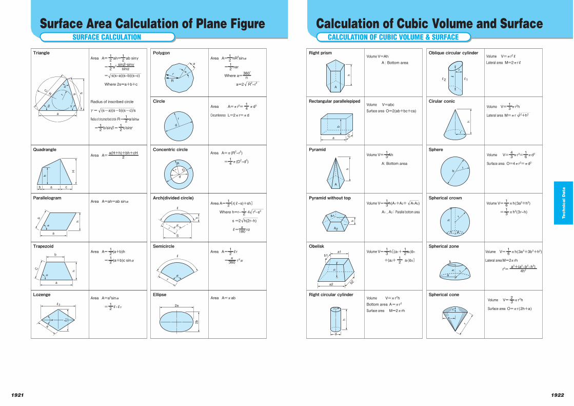
Te
ch
nic
al D
ata
19221921
CALCULATION OF CUBIC VOLUME & SURFACE
Calculation of Cubic Volume and Surface
r
d
r
h
A
b
aC
h
A
A2
A1
h
a2 b2
a1
b1
h
h
d
r
r
r
a
hh
a
a
b
h
h
r
j2 j1
j
Right prism Oblique circular cylinder
Rectangular parallelepiped Cirular conic
Pyramid Sphere
Pyramid without top Spherical crown
Obelisk Spherical zone
Right circular cylinder Spherical cone
r
V=Ah
A : Bottom area
Volume
V=abc
O=2(ab+bc+ca)
Volume
Surface area
V= Ah
A: Bottom area
Volume13
V= h(A1+A2+ A1A2)
A1 , A2 : Parallel bottom area
Volume13
V= h[(a1+ a2)b1
+(a2+ a1)b2]
Volume13
12
12
V=xr2h
A=xr2
M=2xrh
Volume
Bottom area
Surface area
V=xr2j
M=2xrj
Volume
Lateral area
V= xr2h
M=xr r2+h2
Volume
Lateral area
13
V= xr3= xd3
O=4xr2=xd2
Volume
Surface area
43
16
V= xh(3a2+h2)
= xh2(3r−h)
Volume1613
V= xh(3a2+3b2+h2)
M=2xrh
r2=
Volume
Lateral area
16
a2+(a2−b2−h2)4h2
V= xr2h
O=xr (2h+a)
Volume
Surface area
23
SURFACE CALCULATION
Surface Area Calculation of Plane Figure
a
h
b a c
hC
bR
β
z
r
γ
S
r
z
j
r
R
z
r
R
D
d
r
a
r
z
d
H
h
a
b
z
a
b
h
C
j2
a
z
j1
2a
2b
z
j
Triangle Polygon
Circle
Quadrangle Concentric circle
Parallelogram Arch(divided circle)
Trapezoid Semicircle
Lozenge Ellipse
A= ah= ab sinγ
= a2
= s(s−a)(s−b)(s−c)
Where 2s=a+b+c
Area
Radius of inscribed circle
γm (soa)(sob)(soc)/s
Radius of circumscribed circle Rm a/sinz
m b/sinβm c/sinγ
1212
sinβ・sinγsinα
12
12
12
12
A= Areaa(H+h)+bh+cH
2
A= (a+b)h
= (a+b)c sinz
Area1212
A=ah=ab sinzArea
A=a2sinz
= j1j2
Area
12
A= nR2sinz
= nar
Where a=
a=2 R2−r
2
Area1212
360゜n
A=xr2= xd2
L=2xr=xd
Area
Circumference
14
A=x(R2−r
2)
= x(D2−d
2)
Area
14
A= [r(j−s)+sh]
Where h=r− 4 r2−s2
s =2 h(2r−h)
j= rα
Area12
12
x
180
A= jr
= r2z
Area12x
360
A=xabArea
h
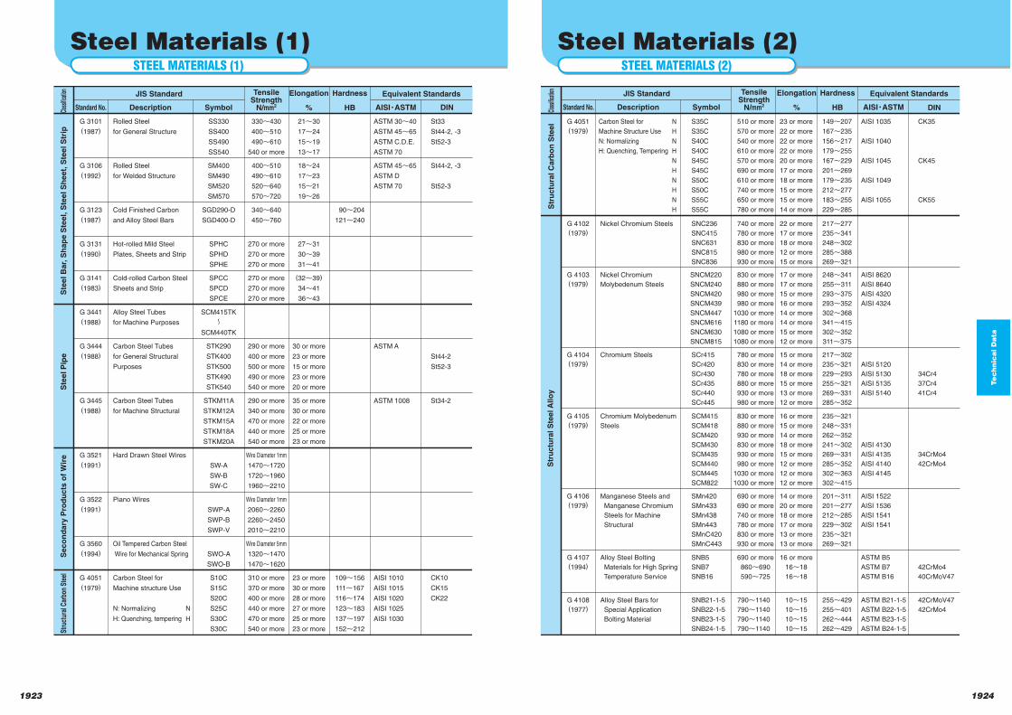
Te
ch
nic
al D
ata
19241923
STEEL MATERIALS (2)
Steel Materials (2)
S35C
S35C
S40C
S40C
S45C
S45C
S50C
S50C
S55C
S55C
510 or more
570 or more
540 or more
610 or more
570 or more
690 or more
610 or more
740 or more
650 or more
780 or more
Carbon Steel for N
Machine Structure Use H
N: Normalizing N
H: Quenching, Tempering H
N
H
N
H
N
H
G 4051
(1979)
23 or more
22 or more
22 or more
22 or more
20 or more
17 or more
18 or more
15 or more
15 or more
14 or more
149n207
167n235
156n217
179n255
167n229
201n269
179n235
212n277
183n255
229n285
AISI 1035
AISI 1040
AISI 1045
AISI 1049
AISI 1055
AISI 8620
AISI 8640
AISI 4320
AISI 4324
CK35
CK45
CK55
34Cr4
37Cr4
41Cr4
SNC236
SNC415
SNC631
SNC815
SNC836
740 or more
780 or more
830 or more
980 or more
930 or more
Nickel Chromium SteelsG 4102
(1979)
22 or more
17 or more
18 or more
12 or more
15 or more
217n277
235n341
248n302
285n388
269n321
SNCM220
SNCM240
SNCM420
SNCM439
SNCM447
SNCM616
SNCM630
SNCM815
830 or more
880 or more
980 or more
980 or more
1030 or more
1180 or more
1080 or more
1080 or more
Nickel Chromium
Molybedenum Steels
G 4103
(1979)
17 or more
17 or more
15 or more
16 or more
14 or more
14 or more
15 or more
12 or more
248n341
255n311
293n375
293n352
302n368
341n415
302n352
311n375
AISI 5120
AISI 5130
AISI 5135
AISI 5140
SCr415
SCr420
SCr430
SCr435
SCr440
SCr445
780 or more
830 or more
780 or more
880 or more
930 or more
980 or more
Chromium SteelsG 4104
(1979)
15 or more
14 or more
18 or more
15 or more
13 or more
12 or more
217n302
235n321
229n293
255n321
269n331
285n352
34CrMo4
42CrMo4
AISI 4130
AISI 4135
AISI 4140
AISI 4145
SCM415
SCM418
SCM420
SCM430
SCM435
SCM440
SCM445
SCM822
830 or more
880 or more
930 or more
830 or more
930 or more
980 or more
1030 or more
1030 or more
Chromium Molybedenum
Steels
G 4105
(1979)
16 or more
15 or more
14 or more
18 or more
15 or more
12 or more
12 or more
12 or more
235n321
248n331
262n352
241n302
269n331
285n352
302n363
302n415
AISI 1522
AISI 1536
AISI 1541
AISI 1541
SMn420
SMn433
SMn438
SMn443
SMnC420
SMnC443
690 or more
690 or more
740 or more
780 or more
830 or more
930 or more
Manganese Steels and
Manganese Chromium
Steels for Machine
Structural
G 4106
(1979)
14 or more
20 or more
18 or more
17 or more
13 or more
13 or more
201n311
201n277
212n285
229n302
235n321
269n321
42CrMo4
40CrMoV47
ASTM B5
ASTM B7
ASTM B16
SNB5
SNB7
SNB16
690 or more
860n690
590n725
Alloy Steel Bolting
Materials for High Spring
Temperature Service
G 4107
(1994)
16 or more
16n18
16n18
42CrMoV47
42CrMo4
ASTM B21-1-5
ASTM B22-1-5
ASTM B23-1-5
ASTM B24-1-5
SNB21-1-5
SNB22-1-5
SNB23-1-5
SNB24-1-5
790n1140
790n1140
790n1140
790n1140
Alloy Steel Bars for
Special Application
Bolting Material
G 4108
(1977)
10n15
10n15
10n15
10n15
255n429
255n401
262n444
262n429
DIN
JIS Standard Equivalent StandardsTensileStrength
N/mm2
Elongation
%
Hardness
HBDescription Symbol AISIYASTMStandard No.Clas
sifica
tion
Str
uc
tura
l C
arb
on
Ste
el
Str
uc
tura
l S
tee
l A
llo
y
STEEL MATERIALS (1)
Steel Materials (1)
SS330
SS400
SS490
SS540
330n430
400n510
490n610
540 or more
Rolled Steel
for General Structure
G 3101
(1987)
JIS Standard Equivalent StandardsTensileStrength
N/mm2
21n30
17n24
15n19
13n17
Elongation
%
Hardness
HBDescription Symbol
ASTM 30n40
ASTM 45n65
ASTM C.D.E.
ASTM 70
AISIYASTM
St33
St44-2, -3
St52-3
SM400
SM490
SM520
SM570
400~510
490~610
520~640
570~720
Rolled Steel
for Welded Structure
G 3106
(1992)
18~24
17~23
15~21
19~26
ASTM 45n65
ASTM D
ASTM 70
St44-2, -3
St52-3
SGD290-D
SGD400-D
340n640
450n760
Cold Finished Carbon
and Alloy Steel Bars
G 3123
(1987)
90n204
121n240
SPHC
SPHD
SPHE
270 or more
270 or more
270 or more
Hot-rolled Mild Steel
Plates, Sheets and Strip
G 3131
(1990)
27n31
30n39
31n41
SPCC
SPCD
SPCE
270 or more
270 or more
270 or more
Cold-rolled Carbon Steel
Sheets and Strip
G 3141
(1983)
(32n39)
34n41
36~43
SCM415TK
SCM440TK
n
Alloy Steel Tubes
for Machine Purposes
G 3441
(1988)
STK290
STK400
STK500
STK490
STK540
290 or more
400 or more
500 or more
490 or more
540 or more
Carbon Steel Tubes
for General Structural
Purposes
G 3444
(1988)
30 or more
23 or more
15 or more
23 or more
20 or more
ASTM A
St44-2
St52-3
STKM11A
STKM12A
STKM15A
STKM18A
STKM20A
290 or more
340 or more
470 or more
440 or more
540 or more
Carbon Steel Tubes
for Machine Structural
G 3445
(1988)
35 or more
30 or more
22 or more
25 or more
23 or more
ASTM 1008 St34-2
SW-A
SW-B
SW-C
Wire Diameter 1mm
1470n1720
1720n1960
1960n2210
Hard Drawn Steel WiresG 3521
(1991)
SWP-A
SWP-B
SWP-V
Wire Diameter 1mm
2060n2260
2260n2450
2010n2210
Piano WiresG 3522
(1991)
SWO-A
SWO-B
Wire Diameter 5mm
1320n1470
1470n1620
Oil Tempered Carbon Steel
Wire for Mechanical Spring
G 3560
(1994)
S10C
S15C
S20C
S25C
S30C
S30C
310 or more
370 or more
400 or more
440 or more
470 or more
540 or more
Carbon Steel for
Machine structure Use
N: Normalizing N
H: Quenching, tempering H
G 4051
(1979)
23 or more
30 or more
28 or more
27 or more
25 or more
23 or more
109n156
111n167
116n174
123n183
137n197
152n212
AISI 1010
AISI 1015
AISI 1020
AISI 1025
AISI 1030
CK10
CK15
CK22
DINStandard No.Clas
sifica
tion
Ste
el
Ba
r, S
ha
pe
Ste
el,
Ste
el
Sh
ee
t, S
tee
l S
trip
Ste
el
Pip
eS
ec
on
da
ry P
rod
uc
ts o
f W
ire
Stru
ctur
al C
arbo
n St
eel
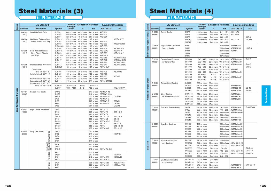
Te
ch
nic
al D
ata
19261925
STEEL MATERIALS (4)
Steel Materials (4)
SUP3
SUP7
SUP9
SUP10
SUP12
SUJ1
SUJ2
SUJ3
SUJ4
SUJ5
SF340A
SF390A
SF440A
SF490A
SF540A
SF590A
SF540B
SF590B
SF640B
SC360
SC410
SC450
SC480
SCW410
SCW450
SCW480
SCW550
SCW620
SCS1
SCS3
SCS6
SCS10
SCS12
SCS16
FC100
FC150
FC200
FC250
FC300
FC350
FCD370
FCD400
FCD450
FCD500
FCD600
FCD700
FCD800
FCMB270
FCMB310
FCMB340
FCMB360
1080 or more
1230 or more
1230 or more
1230 or more
1230 or more
340n440
390n490
440n540
490n590
540n640
590n690
510n600
590n740
640n780
360 or more
410 or more
450 or more
480 or more
410 or more
450 or more
480 or more
550 or more
620 or more
540 or more
590 or more
750 or more
620 or more
480 or more
390 or more
100 or more
150 or more
200 or more
250 or more
300 or more
350 or more
370 or more
400 or more
450 or more
500 or more
600 or more
700 or more
800 or more
270 or more
310 or more
340 or more
360 or more
Spring Steels
High Carbon Chromium
Bearing Steels
Carbon Steel Forgings
for General Use
Carbon Steel Casting
Steel Casting
for Welded Structure
Stainless Steel Casting
Gray Iron Castings
Spheroidal Graphite
Iron Castings
Blackheart Malleable
Iron Castings
G 4801
(1984)
G 4805
(1990)
G 3201
(1988)
G 5101
(1991)
G 5102
(1991)
G 5121
(1991)
G 5501
(1995)
G 5502
(1989)
G 5702
(1988)
8 or more
9 or more
9 or more
10 or more
9 or more
27 or more
25 or more
24 or more
22 or more
20 or more
18 or more
16n21
14n19
10n16
23 or more
21 or more
19 or more
17 or more
21 or more
20 or more
20 or more
18 or more
17 or more
18 or more
16 or more
15 or more
15 or more
28 or more
38 or more
17 or more
12 or more
10 or more
7 or more
3 or more
2 or more
2 or more
5 or more
8 or more
10 or more
14 or more
341n401
363n429
363n429
363n429
363n429
201 or less
201 or less
207 or less
201 or less
207 or less
90 or more
105 or more
121 or more
134 or more
152 or more
167 or more
152 or more
167 or more
183 or more
163n229
170n235
285 or less
302 or less
183 or less
183 or less
201 or less
212 or less
223 or less
241 or less
262 or less
277 or less
179 or less
201 or less
143n217
170n241
192n269
229n302
248n352
AISI 1075
AISI 9260
AISI 6150
ASTM 51100
ASTM 52100
ASTM 1
ASTM classA
ASTM classB
ASTM classC
ASTM D
ASTM classE
ASTM classF
ASTM 60-30
ASTM 65-35
ASTM 70-36
ASTM WCA
ASTM WCB
ASTM WCC
ASTM CA15
ASTM CA15M
ASTM CA6NM
ASTM CF-20
ASTM CF-30
ASTM class20
ASTM class30
ASTM class35
ASTM class40
ASTM class45
ASTM class50
ASTM 60-40-18
ASTM 65-45-12
ASTM 80-55-06
ASTM100-70-03
ASTM 32510
ASTM 35018
55Cr3
50CrV4
100Cr6
St37-3
St44-3
St52-3
GS-45
GS-52
G-X12Cr14
GGG-50
GGG-60
GGG-70
GTS-35-10
DIN
JIS Standard Equivalent StandardsTensileStrength
N/mm2
Elongation
%
Hardness
HBDescription Symbol AISIYASTMStandard No.Clas
sifica
tion
Stee
l for
Spe
cial
Pur
pose
(Con
tinue
d)C
as
t a
nd
Fo
rge
d S
tee
lC
as
t ir
on
STEEL MATERIALS (3)
Steel Materials (3)
SUS201
SUS202
SUS301
SUS301J1
SUS302
SUS303
SUS303Se
SUS304
SUS304L
SUS305
SUS310S
SUS316
SUS317
SUS321
SUS347
SUSXM7
SUS405
SUS429
SUS430
SUS434
SUS444
SUS630
SUS631
SK140
SK120
SK105
SK95
SK85
SK75
SK65
SKH2
SKH3
SKH4
SKH10
SKH51
SKH53
SKH55
SKH57
SKH59
SKS11
SKS2
SKS21
SKS5
SKS7
SKS4
SKS41
SKS43
SKS3
SKS31
SKD1
SKD11
SKD6
SKD7
SKT3
640 or more
590 or more
520 or more
570 or more
520 or more
520 or more
520 or more
520 or more
480 or more
480 or more
520 or more
550 or more
520 or more
520 or more
520 or more
480 or more
410 or more
450 or more
450 or more
450 or more
410 or more
930n1310
1030n1230
Stainless Steel Bars
Hot Rolled Stainless Steel
Plates, Sheets and Strip
Cold Rolled Stainless
Steel Plates, Sheets
and Strip
Stainless Steel Wire Rods
Designation
Bar : SUS***-B
Hot rolled strip : SUS***-HP
Hot rolled strip : SUS***-HS
Cold rolled strip : SUS***-CP
Cold rolled strip : SUS***-CS
Wire : SUS***-WR
Carbon Tool Steels
High Speed Tool Steels
Alloy Tool Steels
G 4303(1991)
G 4304(1991)
G 4305(1991)
G 4308(1991)
G 4401(2000)
G 4403(1983)
G 4404(2000)
40 or more
40 or more
40 or more
45 or more
40 or more
40 or more
40 or more
40 or more
40 or more
40 or more
40 or more
40 or more
40 or more
40 or more
40 or more
40 or more
20 or more
22 or more
22 or more
22 or more
20 or more
5n10
3n5
241 or less
207 or less
207 or less
187 or less
187 or less
187 or less
187 or less
187 or less
187 or less
187 or less
187 or less
187 or less
187 or less
187 or less
187 or less
187 or less
183 or less
183 or less
183 or less
183 or less
217 or less
277n375
192 or less
217 or less
212 or less
212 or less
207 or less
207 or less
201 or less
201 or less
248 or less
269 or less
285 or less
285 or less
255 or less
269 or less
277 or less
293 or less
277 or less
241 or less
217 or less
217 or less
207 or less
217 or less
201 or less
217 or less
212 or less
217 or less
217 or less
248 or less
255 or less
229 or less
229 or less
235 or less
AISI 201
AISI 202
AISI 301
AISI 302
AISI 303
AISI 303e
AISI 304
AISI 304L
AISI 305
AISI 310S
AISI 316
AISI 317
AISI 321
AISI 347
ASTM XM7
AISI 405
AISI 429
AISI 430
AISI 434
ASTM S44400
ASTM W1-13
ASTM W1-111/2
ASTM W1-10
ASTM W1-9
ASTM W1-8
ASTM W1-7
ASTM T1
ASTM T4
ASTM T5
ASTM T15
ASTM M2
ASTM M3-2
ASTM
ASTM
ASTM M42
ASTM W2-91/2
ASTM BD3
ASTM BD2
ASTM H11
ASTM H10
X20CrNi177
X10CrNiS189
X5CrNi1810
X2CrNi1911
X5CrNi1812
X5CrNiMo17122
X2CrNiMo18164
X6CrNiTi1810
X6CrNiNb1810
X6CrA113
X6Cr17
X7CrNiA1177
C105W1
C80W1
C80W1
C70W2
S18-1-2-5
S12-1-4-5
S6-5-3
S6-5-3
S6-5-2-5
S10-4-3-10
S2-10-1-8
105WCr6
105WCr6
X210Cr12
X38CrMoV51
X32CrMoV33
DIN
JIS Standard Equivalent StandardsTensileStrength
N/mm2
Elongation
%
Hardness
HBDescription Symbol AISIYASTMStandard No.Clas
sifica
tion
Ste
el
for
Sp
ec
ial
Pu
rpo
se
For C
uttin
g To
olFo
r Col
d D
ieFo
r Hot
Die
For I
mpa
ctR
esis
tanc
eTo
ol
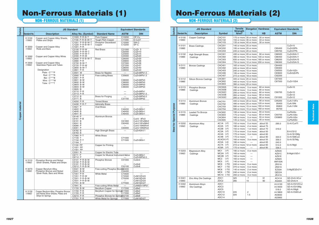
Te
ch
nic
al D
ata
19281927
NON-FERROUS MATERIALS (2)
Non-Ferrous Materials (2)
AC1A (-F)
AC2A (-F)
AC2B (-F)
AC3A (-F)
AC4A (-F)
AC4B (-F)
AC4CH (-F)
AC5A (-0)
AC7A (-F)
AC8A (-F)
MC1 (-F)
MC2A (-F)
MC2B (-F)
MC3 (-F)
MC5 (-F)
MC6 (-T5)
MC7 (-T5)
MC8 (-T5)
MC9 (-T6)
MC10 (-T5)
ZDC1
ZDC2
ADC1
ADC3
ADC5
ADC10
ADC12
ADC14
175 or more155 or more135 or more
145 or more
195 or more
245 or more
430 or more
490 or more
635 or more
755 or more
165 or more
245 or more245 or more195 or more215 or more
345 or more
440 or more390 or more
195 or more
295 or more295 or more265 or more295 or more
440 or more
490 or more
590 or more
590 or more
195 or more
175 or more165 or more145 or more
150 or more
180 or more
150 or more
170 or more
170 or more
170 or more
160 or more
180 or more
210 or more
170 or more
180 or more
160 or more
160 or more
160 or more
140 or more
240 or more
270 or more
140 or more
240 or more
200 or more
325
285
245
225
35 or more35 or more40 or more
25 or more
20 or more
20 or more
20 or more
18 or more
15 or more
12 or more
15 or more
20 or more15 or more15 or more18 or more
25 or more
12 or more20 or more
5 or more
5 or more10 or more 3 or more 5 or more
20 or more
20 or more
15 or more
15 or more
10 or more
7 or more 5 or more 5 or more
5 or more
2 or more
1 or more
5 or more
3 or more
—
3 or more
—
12 or more
—
4 or more
—
—
—
—
5 or more
5 or more
2 or more
2 or more
3 or more
7
10
2
1.5
35 or more 33 or more 30 or more
90 or more
100 or more
165 or more
200 or more
60 or more
80 or more 80 or more 90 or more 90 or more
90 or more
120 or more
160 or more
160 or more
65 or more
60 or more 55 or more 45 or more
about 55
about 75
about 70
about 50
about 60
about 90
about 55
about 65
about 60
about 85
91
82
C85400
C85700
C86500
C86400
C86200
C86300
C84400C90300C90500C83600C92200
C87400C87500
C90700
C91000
C95200
95400
95800
95700
C93700C93800
295.0
319.0
333.0
356.0
242.0
514.0
336.0
AZ63A
AZ91C
AZ91E
AZ92A
AM100A
ZK51A
ZK61A
EZ33A
QE22A
ZE41A
AC41A
AG40A
Aj4130
Aj3500
518.0
Aj3800
A03830
A23900
CuZn15
CuZn33Pb
CuZn37Pb
CuZn35Aj1
CuZn34Aj1
CuZn25Aj5
CuZn25Aj5
CuSn10ZnCuSn5ZnPb
CuZn15Si4
CuSn10
CuSn10CuSn12CuSn12
CuAj10Fe
CuAj9Ni
CuAj10Ni
CuPb5Sn
CuPb10SnCuPb15SnCuPb20Sn
G-AjCu4Ti
B-AjSi12
G-AjSi10Mg
G-AjSi8Cu3
G-AjSi7Mg
G-AjMg5
B-MgAj9Zn1
G-MgSE3Zn27r1
GD-ZnAj4Cul
GD-ZnAj4
GD-AjSi12(Cu)
GD-AjSi10Mg
GD-AjMg9
GD-AjSi9Cu3
Copper Castings
Brass Castings
High Strength Brass
Castings
Bronze Castings
Silicon Bronze Castings
Phosphor Bronze Castings
Aluminium Bronze
Castings
Leaded Tin Bronze
Castings
Aluminium Alloy
Castings
Magnesium Alloy
Castings
Zinc Alloy Die Castings
Aluminium Alloyn
Die Castings
H 5100(1990)
H 5101(1988)
H 5102(1988)
H 5111(1988)
H 5112(1988)
H 5113(1988)
H 5114(1988)
H 5115(1988)
H 5202(1992)
H 5203(1992)
H 5301(1990)
H 5302(1990)
ASTM DIN
CAC101CAC102 CAC103
CAC201
CAC202
CAC203
CAC301
CAC302
CAC303
CAC304
CAC401CAC402CAC403CAC406CAC407
CAC801CAC802 CAC803
CAC502A CAC502BCAC502C CAC503B CAC503C
CAC701CAC702CAC703CAC704
CAC602 CAC603 CAC604 CAC605
JIS Standard Equivalent StandardsTensileStrength
N/mm2
Elongation
%
Hardness
HBDescription SymbolStandard No.Clas
sifica
tion
Ste
el
for
Sp
ec
ial
Pu
rpo
se
NON-FERROUS MATERIALS (1)
Non-Ferrous Materials (1)
C1020 PYRYBYT
C1100 PYRYBYWYT
C1201 PYRYBYWYT
C1220 PYRYBYWYT
C1221 PYR
C2100 PYRYW
C2200 PYRYWYT
C2300 PYRYWYT
C2400 PYRYW
C2600 PYRYBYWYT
C2680 PYR
C2700 BYWYT
C2720 PYRYW
C2800 BYWYT
C2801 PYR
C3501 W
C3560 PYR
C3561 PYR
C3601 BYW
C3602 BYW
C3603 BYW
C3604 BYW
C3605 B
C3710 PYR
C3713 PYR
C3712 B
C3771 B
C4250 PYR
C4430 PYRYT
C4621 P
C4622 B
C4640 B
C4641 B
C6140 P
C6161 PYB
C6191 B
C6241 B
C6280 P
C6301 P
C6782 B
C6783 B
C7060 PYT
C7100 T
C7150 PYT
C7164 T
C1100 PP
C1221 PP
C1401 PP
C2051 R
C6711 P
C6712 P
C5101 PYRYBYW
C5102 PYRYBYW
C5191 PYRYBYW
C5212 PYRYBYW
C5341 BYW
C5441 BYW
C7351 PYR
C7451 PYRYW
C7521 PYRYBYW
C7541 PYRYBYW
C7701 BYW
C7941 B
C1720 BYW
C1700 PYRC1720 PYR
C5210 PYR
C7701 PYR
Pure Copper
Tough Pitch Copper
Phosphor DeoxidizedCopper
Red Brass
Brass
Brass for Nipples
Free-cutting Brass
Brass for Forging
Tinned Brass
Admiralty Brass
Oval Brass
Aluminum Bronze
High Strength Brass
White Brass
Copper for Printing
Copper for Electric Tube
Copper for Musical Instrument Valve
Phosphor Bronze
Free-cutting Phosphor Bronze
White Metal
Free-cutting White Metal
Beryllium Copper
Beryllium Copper for Springs
Phosphor Bronze for Springs
White Metal for Springs
Copper and Copper Alloy Sheets, Plates and Strips
Copper and Copper Alloy Rods and Bars
Copper and Copper Alloy Wires
Copper and Copper Alloy Seamless Pipes and Tubes
Designation
Plate : C****P
Rod : C****R
Bar : C****B
Wire : C****W
Tube : C****T
Phosphor Bronze and Nickel Silver Sheets, Plates and Strips
Copper Berylium Alloy.Phosphor Bronze and Nickel Silver Rods, Bars and Wires
Copper Berylium Alloy, Phosphor Bronze and Nickel Silver Sheets, Plates and Strips for Springs
H 3100(1990)
H 3250(1992)
H 3260(1992)
H 3300(1992)
H 3110(1992)
H 3270(1992)
H 3130(1992)
JIS Standard Equivalent Standards
Description Alloy No. (Symbol) Standard Name
C10200
C11000
C12000C12200
C21000C22000C23000C24000
C26000C26800C27000C27200C28000C28000
—
C35600
C36000C36000C36000C36000
——
—C37700
—C46200C46400C46400
—C61900C62400
—C63000
—
C71000C71500
——
C51000
—C52100
C53400C54400
C73500C74500C75200
—C77000
—
C17200
C17000C17200
C52100
C77000
ASTM
OF-Cu
E-Cu57
SW-C.SF-C.
CuZn 5CuZn10CuZn15CuZn20
CuZn30CuZn36CuZn36CuZn37CuZn40CuZn40
CuZn36Pb1.5
CuZn36Pb1.5
CuZn36Pb3CuZn36Pb3CuZn39Pb3CuZn39Pb3
CuZn39Pb1CuZn38Pb1.5
CuZn39Pb0.5CuZn39Pb2
—CuZn38Sn1CuZn38Sn1CuZn38Sn1
CuAj 8Fe3CuAj10Fe3Mn2CuAj10Fe3Mn2CuAj10Ni5Fe4CuAj10Ni5Fe4
CuZn40Aj1
—CuZn38Sn1
CuZn38Sn1CuZn39Pb0.5
CuSn4
CuSn6CuSn8
—CuNi12Zn24CuNi18Zn20CuNi12Zn24CuNi18Zn27
CuNi8Zn19Pb1
CuBe2
CuBe2CuBe2
CuBe8
CuNi18Zn27
DINStandard No.Clas
sifica
tion
Co
pp
er
ma
teri
al
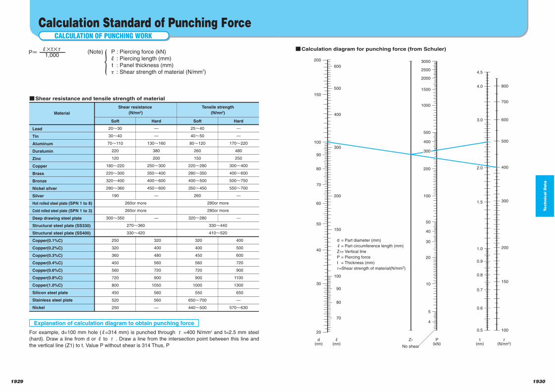
Te
ch
nic
al D
ata
19301929
qCalculation diagram for punching force (from Schuler)
200.5
0.6
0.7
0.8
0.9
1.0
1.5
2.0
3.0
4.0
4.5
4
d(mm)
d = Part diameter (mm)
j = Part circumference length (mm)
Z1= Vertical line
P = Piercing force
t = Thickness (mm)
τ=Shear strength of material(N/mm2)
Z1
No shear
5
10
20
30
40
50
100
200
400
500
1000
1500
2000
2500
3000
P(kN)
t(mm)
30
40
50
60
70
80
90
100
150
200
70
80
90
100
150
200
300
400
500
600
j(mm)
100
150
200
300
400
500
600
700
800
τ(N/mm2)
300
CALCULATION OF PUNCHING WORK
Calculation Standard of Punching Force
Lead
Tin
Aluminum
Duralumin
Zinc
Copper
Brass
Bronze
Nickel silver
Silver
Hot rolled steel plate (SPN 1 to 8)
Cold rolled steel plate (SPN 1 to 3)
Deep drawing steel plate
Structural steel plate (SS330)
Structural steel plate (SS400)
Copper(0.1%C)
Copper(0.2%C)
Copper(0.3%C)
Copper(0.4%C)
Copper(0.6%C)
Copper(0.8%C)
Copper(1.0%C)
Silicon steel plate
Stainless steel plate
Nickel
20n30
30n40
70n110
220
120
180n220
220n300
320n400
280n360
190
300n350
250
320
360
450
560
720
800
450
520
250
260or more
260or more
270n360
330n420
—
—
130n160
380
200
250n300
350n400
400n600
450n600
—
—
320
400
480
560
720
900
1050
560
560
—
Material
Soft Hard
Shear resistance
(N/mm2)
25n40
40n50
80n120
260
150
220n280
280n350
400n500
350n450
260
320~280
320
400
450
560
720
900
1000
550
650n700
440n500
280or more
280or more
330n440
410n520
—
170n220
480
250
300n400
400n600
500n750
550n700
—
—
400
500
600
720
900
1100
1300
650
—
570n630
Soft Hard
Tensile strength
(N/mm2)
qShear resistance and tensile strength of material
Explanation of calculation diagram to obtain punching force
For example, d=100 mm hole ( =314 mm) is punched through τ =400 N/mm2 and t=2.5 mm steel
(hard). Draw a line from d or to τ . Draw a line from the intersection point between this line and
the vertical line (Z1) to t. Value P without shear is 314 Thus, P
P=1,000
t τ (Note) P : Piercing force (kN) : Piercing length (mm)
t : Panel thickness (mm) τ : Shear strength of material (N/mm2)
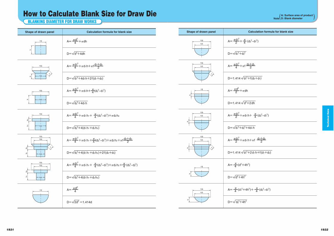
Te
ch
nic
al D
ata
19321931
hd1
f
hd2
h
hd1
hd2
hd2
hd1
hd
hh
hd
h
hd1
f
hd2
h
hd1
hd2
Shape of drawn panel Calculation formula for blank size
A= + (d22−d1
2)xd1
2
2x
4
D= d12+d2
2
A= +xfxd1
2
4d2+d1
2
d1+d2
2
D=1.414 d12+f (d2+d1)
D=1.414 d2+2dh
D=1.414 d12+2d1 h+f (d1+d2)
A= +xdhxd2
2
A= +xd1 h+ (d22−d1
2)xd1
2
2x
4
D= d12+d2
2+4d1 h
A= +xd1 h+xf xd1
2
2
A= (d2+4h2)x
4
A= (d12+4h2)+ (d2
2−d12)
x
4x
4
D= d2+4h2
D= d22+4h2
BLANKING DIAMETER FOR DRAW WORKS
How to Calculate Blank Size for Draw Die
hd
h
hd2
f
h
hd3
f
hd2
h
hd2
h1
h2
hd2
h1
h2
hd1
hd1
hd1
hd1
hd3
hd2
h1
hd
h2
hd1
Shape of drawn panel Calculation formula for blank size
A= +xdhxd2
4
D= d2+4dh
A= +xd1h+xfxd1
2
4d1+d2
2
d2+d3
2
D= d12+4d1h+2f(d1+d2)
A= +xd1h+ (d22−d1
2)xd1
2
4x
4
D= d22+4d1h
A= +xd1 h1+ (d22−d1
2)+xd2 h2xd1
2
4x
4
D= d22+4(d1 h1+d2 h2)
A= +xd1 h1+ (d22−d1
2)+xd2 h2+xfxd1
2
4x
4
D= d22+4(d1 h1+d2 h2)+2f(d2+d3)
A= +xd1 h1+ (d22−d1
2)+xd2 h2+ (d32−d2
2)xd1
2
4
A= xd2
4
x
4x
4
D= d32+4(d1 h1+d2 h2)
D= 2d2 =1.414d
Note( )A: Surface area of productD: Blank diameter
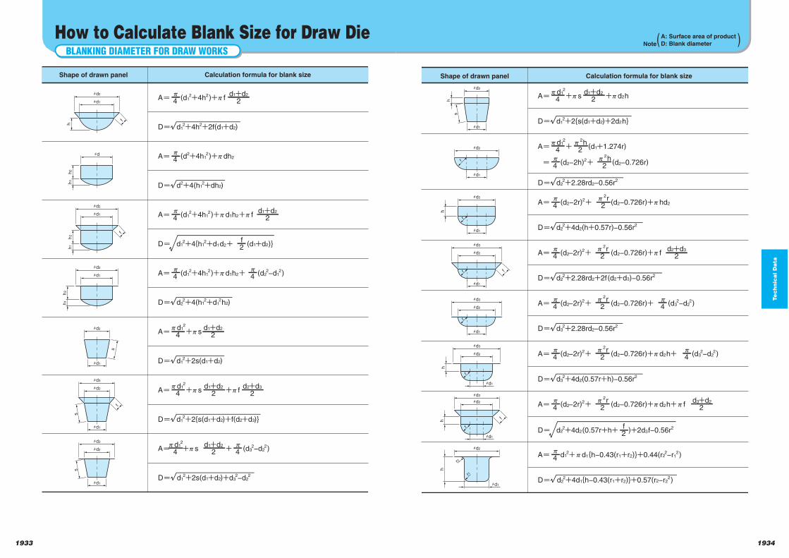
Te
ch
nic
al D
ata
19341933
h
ff
hd2
hd1
s
Dm d22+4d2(0.57r+h+ )+2d3f−0.56r2f
2
hd2
hd1
r
hd2
hd1
r
hh
hd2
hd3
hd1
r
hd2
hd3
hd1
r
hd2
hd3
hd1
r
h
hd2
hd3
hd1
r
h
hd2
hd1
r1
r2
Shape of drawn panel Calculation formula for blank size
Dm d22+2.28rd2+2f(d2+d3)−0.56r2
Dm d22+4d2(h+0.57r)−0.56r2
Dm d32+2.28rd2−0.56r2
Dm d32+4d2(0.57r+h)−0.56r2
Dm d22+4d1{h−0.43(r1+r2)}+0.57(r2−r2
2)
Am (d2−2r)2+ (d2−0.726r)+xhd2x
4
Am (d2−2r)2+ (d2−0.726r)+xfx
4
x
4
x
4
d2+d3
2
Dm d12+2{s(d1+d2)+2d2h}
d1+d2
2Am +xs +xd2hxd1
2
4
Dm d22+2.28rd2−0.56r2
x2h2Am + (d1+1.274r)
xd12
4
x2h2
x2r
2
x2r
2
Am (d2−2r)2+ (d2−0.726r)+ (d32−d2
2)x
4x
2r2
x
4Am (d2−2r)2+ (d2−0.726r)+xd2h+ (d32−d2
2)x
4x
2r2
d3+d2
2Am (d2−2r)2+ (d2−0.726r)+xd2h+xfx
4x
2r2
Am d12+xd1{h−0.43(r1+r2)}+0.44(r2
2−r12)
x
4
m (d2−2h)2+ (d2−0.726r)
BLANKING DIAMETER FOR DRAW WORKS
How to Calculate Blank Size for Draw Die
f
hd2
f
hd3
f
hd1
h
hd2
hd
h1
h2
hd1
h1
h2
hd2
hd1
h1
h2
hd2
hd1
s
hd2
hd1
s
hd3
hd2
hd1
sShape of drawn panel Calculation formula for blank size
Am (d12+4h2)+xf
x
4
Am (d2+4h12)+xdh2
x
4
Dm d12+4h2+2f(d1+d2)
Dm d2+4(h12+dh2)
Dm d22+4(h1
2+d12h2)
Dm d12+2s(d1+d2)
Dm d12+2{s(d1+d2)+f(d2+d3)}
Dm d12+4{h1
2+d1d2+ (d1+d2)}
d1+d2
2
Am (d12+4h1
2)+xd1h2+xfx
4
f2
d1+d2
2
Am (d12+4h1
2)+xd1h2+ (d22−d1
2)x
4
x
4
x
4
d1+d2
2Am +xs xd1
2
4
d1+d2
2d2+d3
2Am +xs +xfxd1
2
4
Dm d12+2s(d1+d2)+d3
2−d22
d1+d2
2Am +xs + (d32−d2
2)xd1
2
4
Note( )A: Surface area of productD: Blank diameter
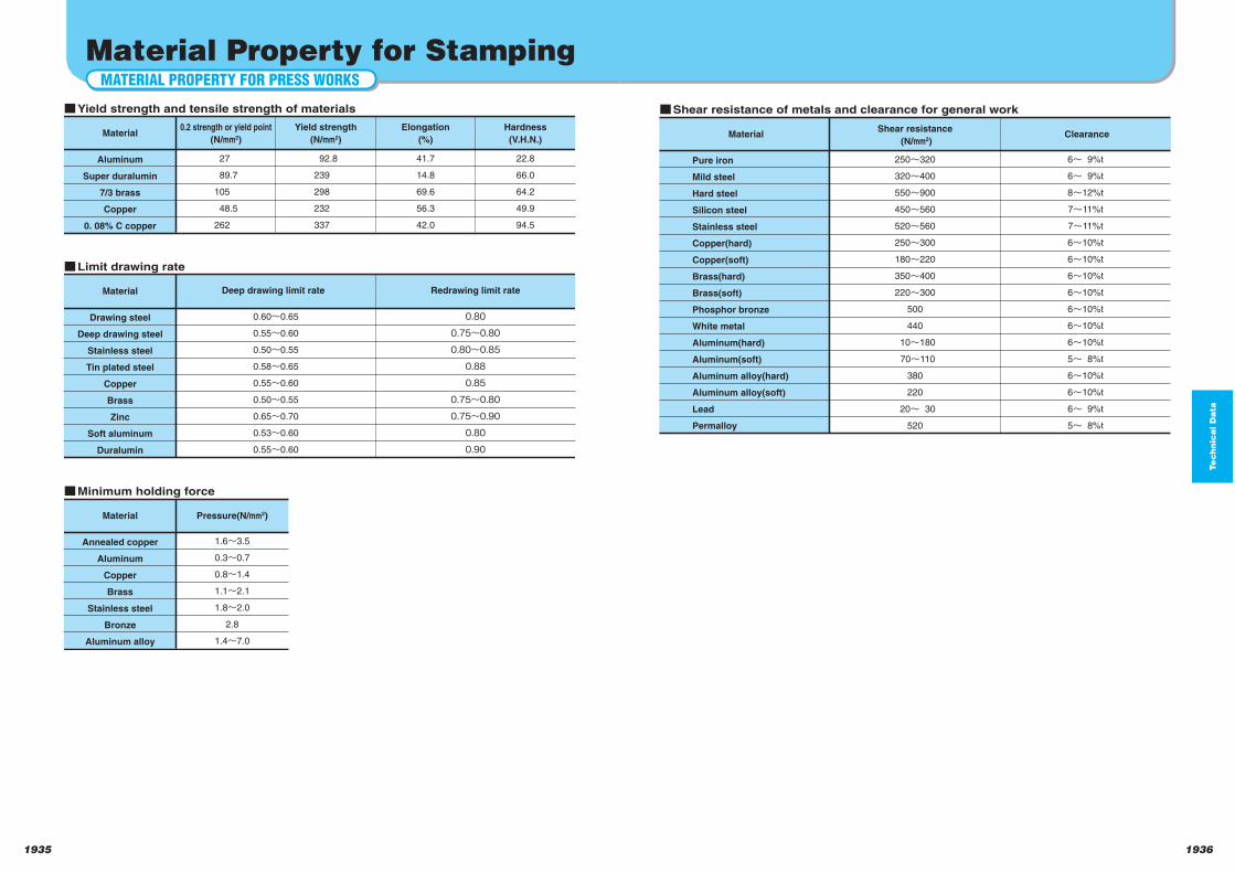
Te
ch
nic
al D
ata
19361935
Pure iron
Mild steel
Hard steel
Silicon steel
Stainless steel
Copper(hard)
Copper(soft)
Brass(hard)
Brass(soft)
Phosphor bronze
White metal
Aluminum(hard)
Aluminum(soft)
Aluminum alloy(hard)
Aluminum alloy(soft)
Lead
Permalloy
250n320
320n400
550n900
450n560
520n560
250n300
180n220
350n400
220n300
500
440
10n180
70n110
380
220
20n 30
520
6n 9%t
6n 9%t
8n12%t
7n11%t
7n11%t
6n10%t
6n10%t
6n10%t
6n10%t
6n10%t
6n10%t
6n10%t
5n 8%t
6n10%t
6n10%t
6n 9%t
5n 8%t
qShear resistance of metals and clearance for general work
MaterialShear resistance
(N/mm2)Clearance
MATERIAL PROPERTY FOR PRESS WORKS
Material Property for Stamping
Aluminum
Super duralumin
7/3 brass
Copper
0. 08% C copper
27
89.7
105
48.5
262
Material
92.8
239
298
232
337
41.7
14.8
69.6
56.3
42.0
22.8
66.0
64.2
49.9
94.5
qYield strength and tensile strength of materials
Drawing steel
Deep drawing steel
Stainless steel
Tin plated steel
Copper
Brass
Zinc
Soft aluminum
Duralumin
0.60~0.65
0.55~0.60
0.50~0.55
0.58~0.65
0.55~0.60
0.50~0.55
0.65~0.70
0.53~0.60
0.55~0.60
Material
0.80
0.75~0.80
0.80~0.85
0.88
0.85
0.75~0.80
0.75~0.90
0.80
0.90
qLimit drawing rate
Annealed copper
Aluminum
Copper
Brass
Stainless steel
Bronze
Aluminum alloy
1.6~3.5
0.3~0.7
0.8~1.4
1.1~2.1
1.8~2.0
2.8
1.4~7.0
Material Pressure(N/mm2)
qMinimum holding force
0.2 strength or yield point
(N/mm2)
Yield strength
(N/mm2)
Elongation
(%)
Hardness
(V.H.N.)
Deep drawing limit rate Redrawing limit rate
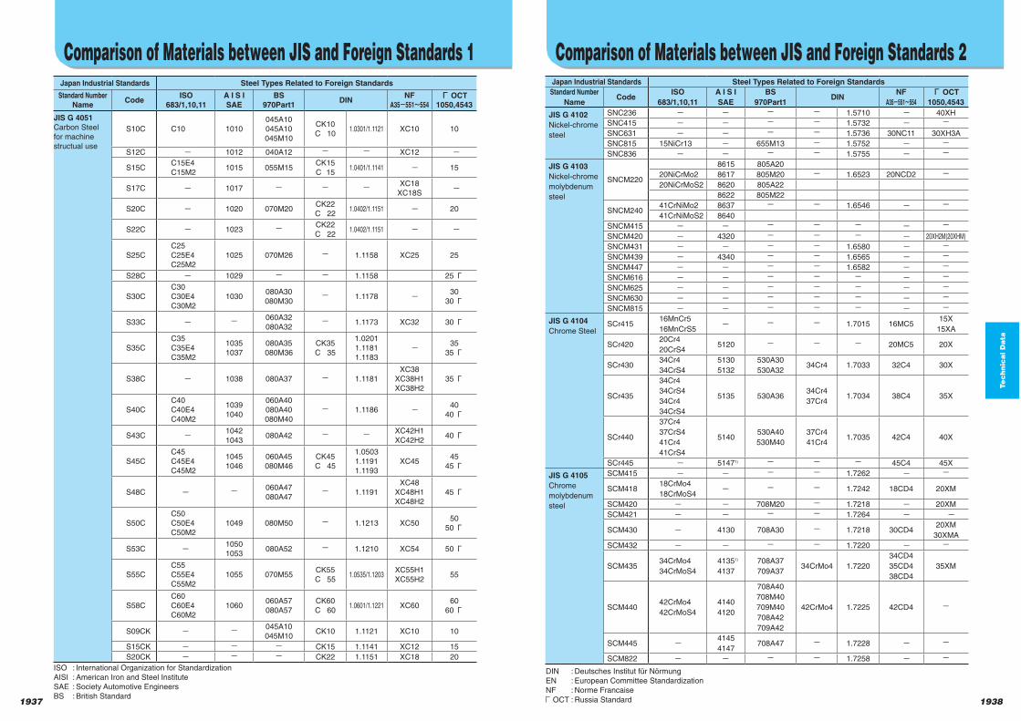
1937 1938
Te
ch
nic
al D
ata
Comparison of Materials between JIS and Foreign Standards 1Japan Industrial Standards Steel Types Related to Foreign Standards
Standard NumberName
CodeISO
683/1,10,11A I S ISAE
BS970Part1
DINNF
A35 551 554Г OCT
1050,4543
JIS G 4051Carbon Steel
for machine
structual use
S10C C10 1010
045A10
045A10
045M10
CK10
C 101.0301/1.1121 XC10 10
S12C 1012 040A12 XC12
S15CC15E4
C15M21015 055M15
CK15
C 151.0401/1.1141 15
S17C 1017XC18
XC18S
S20C 1020 070M20CK22
C 221.0402/1.1151 20
S22C 1023CK22
C 221.0402/1.1151
S25C
C25
C25E4
C25M2
1025 070M26 1.1158 XC25 25
S28C 1029 1.1158 25Г
S30C
C30
C30E4
C30M2
1030080A30
080M301.1178
30
30Г
S33C 060A32
080A321.1173 XC32 30Г
S35C
C35
C35E4
C35M2
1035
1037
080A35
080M36
CK35
C 35
1.0201
1.1181
1.1183
35
35Г
S38C 1038 080A37 1.1181
XC38
XC38H1
XC38H2
35Г
S40C
C40
C40E4
C40M2
1039
1040
060A40
080A40
080M40
1.1186 40
40Г
S43C 1042
1043080A42
XC42H1
XC42H240Г
S45C
C45
C45E4
C45M2
1045
1046
060A45
080M46
CK45
C 45
1.0503
1.1191
1.1193
XC4545
45Г
S48C 060A47
080A471.1191
XC48
XC48H1
XC48H2
45Г
S50C
C50
C50E4
C50M2
1049 080M50 1.1213 XC5050
50Г
S53C 1050
1053080A52 1.1210 XC54 50Г
S55C
C55
C55E4
C55M2
1055 070M55CK55
C 551.0535/1.1203
XC55H1
XC55H255
S58C
C60
C60E4
C60M2
1060060A57
080A57
CK60
C 601.0601/1.1221 XC60
60
60Г
S09CK 045A10
045M10CK10 1.1121 XC10 10
S15CK CK15 1.1141 XC12 15
S20CK CK22 1.1151 XC18 20
Japan Industrial Standards Steel Types Related to Foreign Standards
Standard Number
NameCode
ISO
683/1,10,11
A I S I
SAE
BS
970Part1DIN
NF
A35 551 554
Г OCT
1050,4543
JIS G 4102
Nickel-chrome
steel
SNC236 1.5710 40XH
SNC415 1.5732
SNC631 1.5736 30NC11 30XH3A
SNC815 15NiCr13 655M13 1.5752
SNC836 1.5755
JIS G 4103
Nickel-chrome
molybdenum
steel
SNCM220
8615 805A20
20NiCrMo2 8617 805M20 1.6523 20NCD2
20NiCrMoS2 8620 805A22
8622 805M22
SNCM24041CrNiMo2 8637 1.6546
41CrNiMoS2 8640
SNCM415
SNCM420 4320 20XH2M(20XHM)
SNCM431 1.6580
SNCM439 4340 1.6565
SNCM447 1.6582
SNCM616
SNCM625
SNCM630
SNCM815
JIS G 4104
Chrome SteelSCr415
16MnCr5
16MnCrS5 1.7015 16MC5
15X
15XA
SCr42020Cr4
20CrS45120 20MC5 20X
SCr43034Cr4
34CrS4
5130
5132
530A30
530A3234Cr4 1.7033 32C4 30X
SCr435
34Cr4
34CrS4
34Cr4
34CrS4
5135 530A3634Cr4
37Cr41.7034 38C4 35X
SCr440
37Cr4
37CrS4
41Cr4
41CrS4
5140530A40
530M40
37Cr4
41Cr41.7035 42C4 40X
SCr445 51471) 45C4 45X
JIS G 4105
Chrome
molybdenum
steel
SCM415 1.7262
SCM41818CrMo4
18CrMoS4 1.7242 18CD4 20XM
SCM420 708M20 1.7218 20XM
SCM421 1.7264
SCM430 4130 708A30 1.7218 30CD420XM
30XMA
SCM432 1.7220
SCM43534CrMo4
34CrMoS4
41351)
4137
708A37
709A3734CrMo4 1.7220
34CD4
35CD4
38CD4
35XM
SCM44042CrMo4
42CrMoS4
4140
4120
708A40
708M40
709M40
708A42
709A42
42CrMo4 1.7225 42CD4
SCM445 4145
4147708A47 1.7228
SCM822 1.7258
Comparison of Materials between JIS and Foreign Standards 2
ISO : International Organization for Standardization
AISI : American Iron and Steel Institute
SAE : Society Automotive Engineers
BS : British Standard
DIN : Deutsches Institut für Nörmung
EN : European Committee Standardization
NF : Norme Francaise
ГOCT : Russia Standard

1939 1940
Te
ch
nic
al D
ata
Te
ch
nic
al D
ata
Japan Industrial Standards Steel Types Related to Foreign Standards
Standard NumberName
CodeISO
683/1,10,11A I S ISAE
BS970Part1
DINNF
A35 551 554Г OCT
1050,4543
JIS G 4106
Structual
manganese
steel for
machine
Structual use
and
manganess
chrome steel
SMn420 22Mn6 1522120M19
150M191.1160 20M5
SMn433 15361)120M36
150M361.1166 35M5
30Г 2
35Г 2
SMn438 36Mn6 1541 150M36 1.1167 40M635Г 2
40Г 2
SMn443 42Mn6 1541135M44
150M4040M6
40Г 2
45Г 2
SMnC420 1.1133
SMnC443
JIS G 4202Aluminum
chrome
molybdenum
steel
SACM645 41CrAIMo74 905M39 41CrAIMo72) 1.8509 40CAD6.12
JIS G 4052
Structual steel
with
guaranteed
hardenability
(H steel)
SMn420H 22Mn6 1522H 1.1160 20M5
SMn433H 1.1166 35M5
SMn438H 36Mn6 1541H 1.1167 40M6
SMn443H 42Mn6 1541H 40M6
SMnC420H 1.7147
SMnC443H
SCr415H16MnCr5
16MnCrS51.7015 16MC5 15X
SCr420H20Cr4
20CrS45120H 20MC5 20X
SCr430H34Cr4
34CrS4
5130H
5132H530H32 34Cr4 1.7033 32C4 30X
SCr435H
34Cr4
34CrS4
37Cr4
37CrS4
5135H 530H3634Cr4
37Cr41.7034 38C4 35X
SCr440H
37Cr4
37CrS4
41Cr4
41CrS4
5140H 530H4037Cr4
41Cr41.7035 42C4 40X
SCM415H 1.7262
SCM418H18CrMo4
18CrMoS41.7242 18CD4
SCM420H 708H20 1.7264
SCM435H34CrMo4
34CrMoS4
4135H
4137H708H37 34CrMo4 1.7220
34CD4
38CD4
SCM440H42CrMo4
42CrMoS4
4140H
4142H708H42
42CrMo4 1.7225 42CD4
SCM445H 4145H
4147H708H45 1.7228
SCM822H 1.7258
SNC415H 1.5732
SNC631H 1.5736 30NC11
SNC815H 15NiCr13 655H13 1.5752
SNCM220H20NiCrMo2
20NiCrMoS2
8617H
8620H
8622H
805H17
805H20
805H22
1.6523 20NCD2
SNCM420H 4320H
Comparison of Materials between JIS and Foreign Standards 3 Comparison of Materials between JIS and Foreign Standards 4
Japan Industrial Standards Steel Types Related to Foreign Standards
Standard NumberName
CodeISO
683/1,10,11A I S ISAE
BS970Part1
DINNF
A35 551 554Г OCT
1050,4543
JIS G 4107
High-
temperature
alloy steel for
bolts
SNB5 501 BS1506-625
SNB7
4140
4142
4145
708A40
708M40
709M40
708A42
709A42
BS1506-621
Grade A
42CrMo43) 1.7225 42CD4
SNB16 BS1506-661 40CrMoV473) 1.7711 42CDV44)
JIS G 4108
Steel bar for
special-purpose
alloy steel bolt
SNB21-1 5 BS1506-661 40CrMoV473) 1.7711 42CDV44)
SNB22-1 5 4142708A42
709A4242CrMo43) 1.7223 42CD4
SNB23-1 5 E4340 1.6562SNB24-1 5 1.6565
Note : 1) Not specified by AISI.
2) DIN 17211
3) DIN 17240, DIN 1654Part4
4) NFA 35-558
Aluminum and aluminum alloy extender * : Regulation of chemical components
** : Regulation of mechanical properities
Japan Industrial Standards Steel Types Related to Foreign Standards
Standard NumberName
Code
ISO6361:90
ISO209:89
AA
AA:93
ASTM
B209M:95
FS
QQ-A-250
BSEN485-2:95**
BSEN573-3:95*
DINEN485-2:95**
DINEN573-3:94*
JIS H 4000:88
Aluminum
sheet and bars
A2017P AlCu4MgSi(A) EN AW-2017A EN AW-2017A
A5052P AlMg2.5 5052 50525052
(QQ-A-250/8F)EN AW-5052 EN AW-5052
A6061P 6061 60616061
(QQ-A-250/11F)EN AW-6061 EN AW-6061
A7075P AlZn5.5MgCu 7075 70757075
(QQ-A-250/12F)EN AW-7075 EN AW-7075
( )
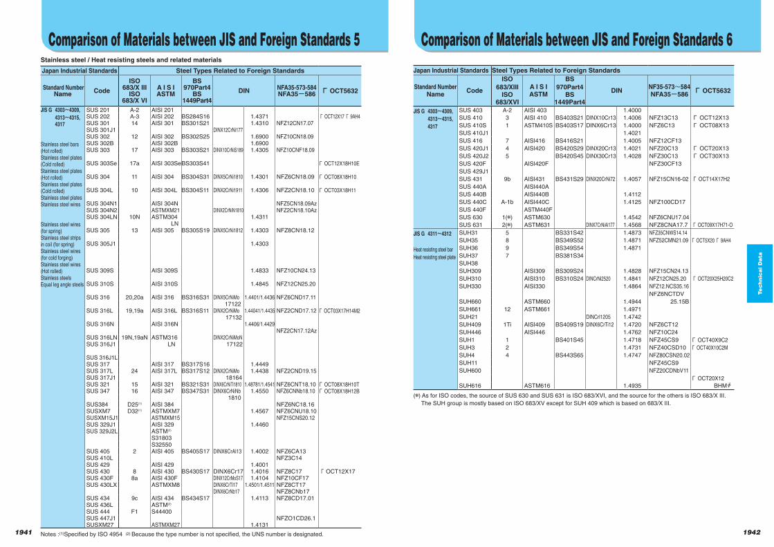
1941 1942
Te
ch
nic
al D
ata
Te
ch
nic
al D
ata
Stainless steel / Heat resisting steels and related materials
Japan Industrial Standards Steel Types Related to Foreign Standards
Standard NumberName
Code
ISO683/X III
ISO683/X VI
A I S IASTM
BS970Part4
BS1449Part4
DINNFA35-573-584NFA35 586 Г OCT5632
SUS 201 A-2 AISI 201SUS 202 A-3 AISI 202 BS284S16 1.4371 ГOCT12X17Г 9AH4SUS 301 14 AISI 301 BS301S21 1.4310 NFZ12CN17.07SUS 301J1 DINX12CrNi177SUS 302 12 AISI 302 BS302S25 1.6900 NFZ10CN18.09SUS 302B AISI 302B 1.6900SUS 303 17 AISI 303 BS303S21 DINX10CrNiS189 1.4305 NFZ10CNF18.09
SUS 303Se 17a AISI 303SeBS303S41 Г OCT12X18H10E
SUS 304 11 AISI 304 BS304S31 DINX5CrNi1810 1.4301 NFZ6CN18.09 Г OCT08X18H10
SUS 304L 10 AISI 304L BS304S11 DINX2CrNi1911 1.4306 NFZ2CN18.10 Г OCT03X18H11
SUS 304N1 AISI 304N NFZ5CN18.09AzSUS 304N2 ASTMXM21 DINX2CrNiN1810 NFZ2CN18.10AzSUS 304LN 10N ASTM304 1.4311
LNSUS 305 13 AISI 305 BS305S19 DINX5CrNi1812 1.4303 NFZ8CN18.12
SUS 305J1 1.4303
SUS 309S AISI 309S 1.4833 NFZ10CN24.13
SUS 310S AISI 310S 1.4845 NFZ12CN25.20
SUS 316 20,20a AISI 316 BS316S31 DINX5CrNiMo 1.4401/1.4436 NFZ6CND17.11 17122
SUS 316L 19,19a AISI 316L BS316S11 DINX2CrNiMo 1.44041/1.4435 NFZ2CND17.12 Г OCT03X17H14M2 17132
SUS 316N AISI 316N 1.4406/1.4429NFZ2CN17.12Az
SUS 316LN 19N,19aN ASTM316 DINX2CrNiMoN SUS 316J1 LN 17122
SUS 316J1LSUS 317 AISI 317 BS317S16 1.4449SUS 317L 24 AISI 317L BS317S12 DINX2CrNiMo 1.4438 NFZ2CND19.15SUS 317J1 18164SUS 321 15 AISI 321 BS321S31 DINX6CrNiTi1810 1.48781/1.4541 NFZ6CNT18.10 Г OCT08X18H10TSUS 347 16 AISI 347 BS347S31 DINX6CrNiNb 1.4550 NFZ6CNNb18.10 Г OCT08X18H12B
1810SUS384 D25(1) AISI 384 NFZ6NC18.16SUSXM7 D32(1) ASTMXM7 1.4567 NFZ6CNU18.10SUSXM15J1 ASTMXM15 NFZ15CNS20.12SUS 329J1 AISI 329 1.4460SUS 329J2L ASTM(2)
S31803S32550
SUS 405 2 AISI 405 BS405S17 DINX6CrAl13 1.4002 NFZ6CA13SUS 410L NFZ3C14SUS 429 AISI 429 1.4001SUS 430 8 AISI 430 BS430S17 DINX6Cr17 1.4016 NFZ8C17 ГOCT12X17SUS 430F 8a AISI 430F DINX12CrMoS17 1.4104 NFZ10CF17SUS 430LX ASTMXM8 DINX6CrTi17 1.4501/1.4511 NFZ8CT17
DINX6CrNb17 NFZ8CNb17SUS 434 9c AISI 434 BS434S17 1.4113 NFZ8CD17.01SUS 436L ASTM(2)
SUS 444 F1 S44400SUS 447J1 NFZO1CD26.1SUSXM27 ASTMXM27 1.4131
Notes :(1)Specified by ISO 4954 (2) Because the type number is not specified, the UNS number is designated.
JIS G 4303 4309,
4313 4315, 4317
Stainless steel bars(Hot rolled)Stainless steel plates(Cold rolled)Stainless steel plates(Hot rolled)Stainless steel plates(Cold rolled)Stainless steel platesStainless steel wires
Stainless steel wires(for spring)Stainless steel stripsin coil (for spring)Stainless steel wires(for cold forging)Stainless steel wires(Hot rolled)Stainless steelsEqual leg angle steels
Comparison of Materials between JIS and Foreign Standards 5
Japan Industrial Standards Steel Types Related to Foreign Standards
Standard NumberName
Code
ISO
683/XIIIISO
683/XVI
A I S IASTM
BS
970Part4BS
1449Part4
DINNF35-573 584NFA35 586
Г OCT5632
SUS 403 A-2 AISI 403 1.4000
SUS 410 3 AISI 410 BS403S21 DINX10Cr13 1.4006 NFZ13C13 Г OCT12X13
SUS 410S 1 ASTM410S BS403S17 DINX6Cr13 1.4000 NFZ6C13 Г OCT08X13
SUS 410J1 1.4021
SUS 416 7 AISI416 BS416S21 1.4005 NFZ12CF13
SUS 420J1 4 AISI420 BS420S29 DINX20Cr13 1.4021 NFZ20C13 Г OCT20X13
SUS 420J2 5 BS420S45 DINX30Cr13 1.4028 NFZ30C13 Г OCT30X13
SUS 420F AISI420F NFZ30CF13
SUS 429J1
SUS 431 9b AISI431 BS431S29 DINX20CrNi72 1.4057 NFZ15CN16-02 Г OCT14X17H2
SUS 440A AISI440A
SUS 440B AISI440B 1.4112
SUS 440C A-1b AISI440C 1.4125 NFZ100CD17
SUS 440F ASTM440F
SUS 630 1( ) ASTM630 1.4542 NFZ6CNU17.04
SUS 631 2( ) ASTM631 DINX7CrNiAl177 1.4568 NFZ8CNA17.7 Г OCT09X17H71-O
SUH31 5 BS331S42 1.4873 NFZ35CNWS14.14
SUH35 8 BS349S52 1.4871 NFZ52CMN21.09 Г OCT5X20Г 9AH4
SUH36 9 BS349S54 1.4871
SUH37 7 BS381S34
SUH38
SUH309 AISI309 BS309S24 1.4828 NFZ15CN24.13
SUH310 AISI310 BS310S24 DINCrNi2520 1.4841 NFZ12CN25.20 Г OCT20X25H20C2
SUH330 AISI330 1.4864 NFZ12.NCS35.16
NFZ6NCTDV
SUH660 ASTM660 1.4944 25.15B
SUH661 12 ASTM661 1.4971
SUH21 DINCrl1205 1.4742
SUH409 1Ti AISI409 BS409S19 DINX6CrTi12 1.4720 NFZ6CT12
SUH446 AISI446 1.4762 NFZ10C24
SUH1 1 BS401S45 1.4718 NFZ45CS9 Г OCT40X9C2
SUH3 2 1.4731 NFZ40CSD10 Г OCT40X10C2M
SUH4 4 BS443S65 1.4747 NFZ80CSN20.02
SUH11 NFZ45CS9
SUH600 NFZ20CDNbV11
Г OCT20X12
SUH616 ASTM616 1.4935 BHM
( ) As for ISO codes, the source of SUS 630 and SUS 631 is ISO 683/XVI, and the source for the others is ISO 683/X III.
The SUH group is mostly based on ISO 683/XV except for SUH 409 which is based on 683/X III.
JIS G 4303 4309,
4313 4315,
4317
JIS G 4311 4312
Heat resisting steel bar
Heat resisting steel plate
Comparison of Materials between JIS and Foreign Standards 6
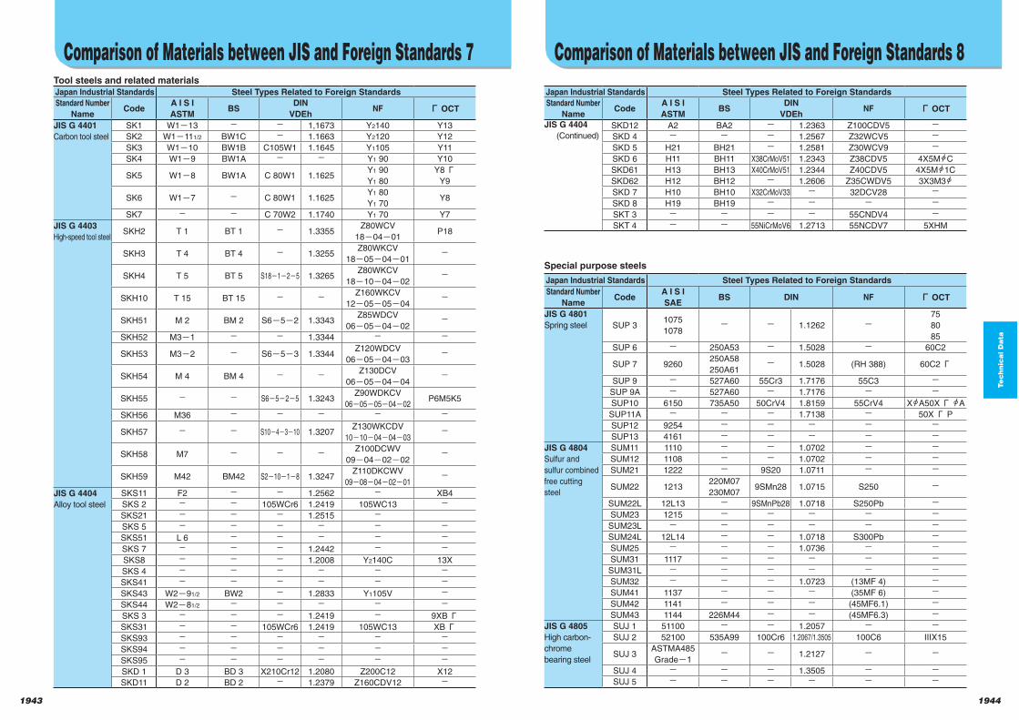
1943 1944
Te
ch
nic
al D
ata
Te
ch
nic
al D
ata
Tool steels and related materialsJapan Industrial Standards Steel Types Related to Foreign Standards
Standard Number
NameCode
A I S I
ASTMBS
DIN
VDEhNF Г OCT
SK1 W1 13 1,1673 Y2140 Y13
SK2 W1 111/2 BW1C 1.1663 Y2120 Y12
SK3 W1 10 BW1B C105W1 1.1645 Y1105 Y11
SK4 W1 9 BW1A Y1 90 Y10
SK5 W1 8 BW1A C 80W1 1.1625Y1 90
Y1 80
Y8ГY9
SK6 W1 7 C 80W1 1.1625Y1 80
Y1 70Y8
SK7 C 70W2 1.1740 Y1 70 Y7
SKH2 T 1 BT 1 1.3355Z80WCV
18 04 01P18
SKH3 T 4 BT 4 1.3255Z80WKCV
18 05 04 01
SKH4 T 5 BT 5 S18 1 2 5 1.3265Z80WKCV
18 10 04 02
SKH10 T 15 BT 15Z160WKCV
12 05 05 04
SKH51 M 2 BM 2 S6 5 2 1.3343Z85WDCV
06 05 04 02
SKH52 M3 1 1.3344
SKH53 M3 2 S6 5 3 1.3344Z120WDCV
06 05 04 03
SKH54 M 4 BM 4Z130DCV
06 05 04 04
SKH55 S6 5 2 5 1.3243Z90WDKCV
06 05 05 04 02P6M5K5
SKH56 M36
SKH57 S10 4 3 10 1.3207Z130WKCDV
10 10 04 04 03
SKH58 M7Z100DCWV
09 04 02 02
SKH59 M42 BM42 S2 10 1 8 1.3247Z110DKCWV
09 08 04 02 01
SKS11 F2 1.2562 XB4
SKS 2 105WCr6 1.2419 105WC13
SKS21 1.2515
SKS 5
SKS51 L 6
SKS 7 1.2442
SKS8 1.2008 Y2140C 13X
SKS 4
SKS41
SKS43 W2 91/2 BW2 1.2833 Y1105V
SKS44 W2 81/2
SKS 3 1.2419 9XBГSKS31 105WCr6 1.2419 105WC13 XBГSKS93
SKS94
SKS95
SKD 1 D 3 BD 3 X210Cr12 1.2080 Z200C12 X12
SKD11 D 2 BD 2 1.2379 Z160CDV12
JIS G 4401
Carbon tool steel
JIS G 4403
High-speed tool steel
JIS G 4404
Alloy tool steel
Comparison of Materials between JIS and Foreign Standards 7
Japan Industrial Standards Steel Types Related to Foreign Standards
Standard Number
NameCode
A I S I
ASTMBS
DIN
VDEhNF Г OCT
SKD12 A2 BA2 1.2363 Z100CDV5
SKD 4 1.2567 Z32WCV5
SKD 5 H21 BH21 1.2581 Z30WCV9
SKD 6 H11 BH11 X38CrMoV51 1.2343 Z38CDV5 4X5M C
SKD61 H13 BH13 X40CrMoV51 1.2344 Z40CDV5 4X5M 1C
SKD62 H12 BH12 1.2606 Z35CWDV5 3X3M3
SKD 7 H10 BH10 X32CrMoV33 32DCV28
SKD 8 H19 BH19
SKT 3 55CNDV4
SKT 4 55NiCrMoV6 1.2713 55NCDV7 5XHM
Special purpose steels
Japan Industrial Standards Steel Types Related to Foreign Standards
Standard Number
NameCode
A I S I
SAEBS DIN NF Г OCT
SUP 31075
10781.1262
75
80
85
SUP 6 250A53 1.5028 60C2
SUP 7 9260250A58
250A611.5028 (RH 388) 60C2Г
SUP 9 527A60 55Cr3 1.7176 55C3
SUP 9A 527A60 1.7176
SUP10 6150 735A50 50CrV4 1.8159 55CrV4 X A50XГ A
SUP11A 1.7138 50X Г P
SUP12 9254
SUP13 4161
SUM11 1110 1.0702
SUM12 1108 1.0702
SUM21 1222 9S20 1.0711
SUM22 1213220M07
230M079SMn28 1.0715 S250
SUM22L 12L13 9SMnPb28 1.0718 S250Pb
SUM23 1215
SUM23L
SUM24L 12L14 1.0718 S300Pb
SUM25 1.0736
SUM31 1117
SUM31L
SUM32 1.0723 (13MF 4)
SUM41 1137 (35MF 6)
SUM42 1141 (45MF6.1)
SUM43 1144 226M44 (45MF6.3)
SUJ 1 51100 1.2057
SUJ 2 52100 535A99 100Cr6 1.2067/1.3505 100C6 IIIX15
SUJ 3ASTMA485
Grade 11.2127
SUJ 4 1.3505
SUJ 5
JIS G 4404
(Continued)
Comparison of Materials between JIS and Foreign Standards 8
JIS G 4801
Spring steel
JIS G 4804
Sulfur and
sulfur combined
free cutting
steel
JIS G 4805
High carbon-
chrome
bearing steel
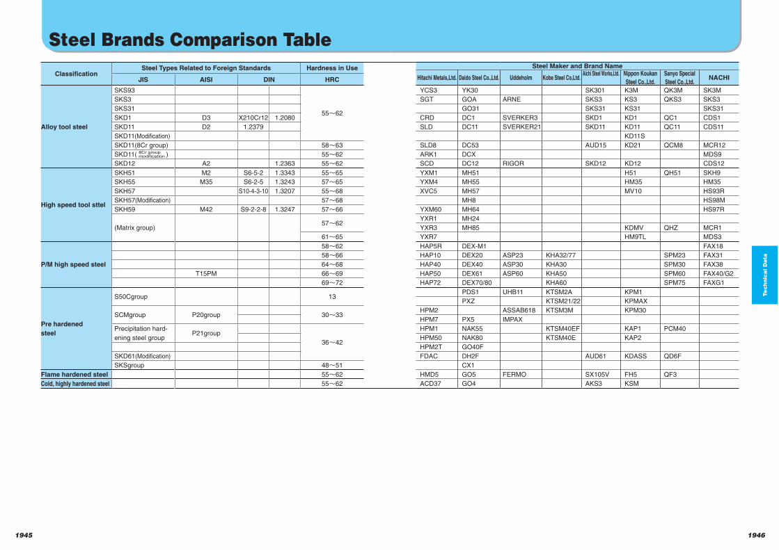
1945 1946
Te
ch
nic
al D
ata
ClassificationSteel Types Related to Foreign Standards Hardness in Use
JIS AISI DIN HRC
Alloy tool steel
SKS93
55 62
SKS3
SKS31
SKD1 D3 X210Cr12 1.2080
SKD11 D2 1.2379
SKD11(Modification)
SKD11(8Cr group) 58 63
SKD11( ) 55 62
SKD12 A2 1.2363 55 62
High speed tool sttel
SKH51 M2 S6-5-2 1.3343 55 65
SKH55 M35 S6-2-5 1.3243 57 65
SKH57 S10-4-3-10 1.3207 55 68
SKH57(Modification) 57 68
SKH59 M42 S9-2-2-8 1.3247 57 66
(Matrix group)57 62
61 65
P/M high speed steel
58 62
58 66
64 68
T15PM 66 69
69 72
Pre hardened
steel
S50Cgroup 13
SCMgroup P20group 30 33
Precipitation hard-
ening steel groupP21group
36 42
SKD61(Modification)
SKSgroup 48 51
Flame hardened steel 55 62
Cold, highly hardened steel 55 62
Steel Brands Comparison Table
Steel Maker and Brand Name
Hitachi Metals,Ltd. Daido Steel Co.,Ltd. Uddeholm Kobe Steel Co,Ltd.Aichi Steel Works,Ltd.
Nippon Koukan
Steel Co.,Ltd.
Sanyo Special
Steel Co.,Ltd.NACHI
YCS3 YK30 SK301 K3M QK3M SK3M
SGT GOA ARNE SKS3 KS3 QKS3 SKS3
GO31 SKS31 KS31 SKS31
CRD DC1 SVERKER3 SKD1 KD1 QC1 CDS1
SLD DC11 SVERKER21 SKD11 KD11 QC11 CDS11
KD11S
SLD8 DC53 AUD15 KD21 QCM8 MCR12
ARK1 DCX MDS9
SCD DC12 RIGOR SKD12 KD12 CDS12
YXM1 MH51 H51 QH51 SKH9
YXM4 MH55 HM35 HM35
XVC5 MH57 MV10 HS93R
MH8 HS98M
YXM60 MH64 HS97R
YXR1 MH24
YXR3 MH85 KDMV QHZ MCR1
YXR7 HM9TL MDS3
HAP5R DEX-M1 FAX18
HAP10 DEX20 ASP23 KHA32/77 SPM23 FAX31
HAP40 DEX40 ASP30 KHA30 SPM30 FAX38
HAP50 DEX61 ASP60 KHA50 SPM60 FAX40/G2
HAP72 DEX70/80 KHA60 SPM75 FAXG1
PDS1 UHB11 KTSM2A KPM1
PXZ KTSM21/22 KPMAX
HPM2 ASSAB618 KTSM3M KPM30
HPM7 PX5 IMPAX
HPM1 NAK55 KTSM40EF KAP1 PCM40
HPM50 NAK80 KTSM40E KAP2
HPM2T GO40F
FDAC DH2F AUD61 KDASS QD6F
CX1
HMD5 GO5 FERMO SX105V FH5 QF3
ACD37 GO4 AKS3 KSM
8Cr groupmodification
1947 1948
お取り引きにあたってCompany Outline
Head-quarter and Branches …………………………………………………………P.1949
Locations of Overseas …………………………………………………… P.1950 to 1953
Company Outline
Company Outline
Co
mp
an
y O
utl
ine
1947
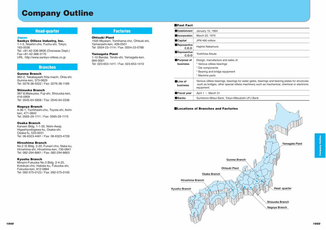
19501949
Gunma Branch
Osaka Branch
Hiroshima Branch
Kyushu Branch Head -quarter
Nagoya Branch
Shizuoka Branch
Ohtsuki Plant
Yamagata Plant
Company Outline
January 10, 1964
March 25, 1970
JPN ¥90 million
Hajime Nakamura
Various oilless bearings, bearings for water gates, bearings and bearing plates for structures
such as bridges, other special oilless machinery such as mechanical, chemical or electronic
equipment.
Sumitomo-Mitsui Bank, Tokyo-Mitsubishi UFJ Bank
Design, manufacture and sales of:
* Various oilless bearings
* Die components
* Bearing and bridge equipment
* Machine parts
qIncorporation
qEstablishment
qCapital
qRepresentive
C.E.O
Yoshihisa AtsutaqRepresentive
C.O.O
qLine of
business
April 1 o March 31qFiscal year
qBanks
qPurpose of
business
Co
mp
an
y O
utl
ine
Head-quarter
JapanSankyo Oilless Industry, Inc.1-1-5, Nisshin-cho, Fuchu-shi, Tokyo, 183-0036 Tel: +81-42-336-9606 (Overseas Dept.) Fax:+81-42-368-3170URL http://www.sankyo-oilless.co.jp
Branches
Gunma Branch962-2, Takabayashi Kita-machi, Ohta-shi, Gunma-ken, 373-0829Tel: 0276-38-5522 / Fax: 0276-38-1189
Shizuoka Branch387-8,Matsuoka, Fuji-shi, Shizuoka-ken, 416-0909Tel: 0545-64-5858 / Fax: 0545-64-0336
Nagoya Branch4-36-1, Tuchihashi-cho, Toyota-shi, Aichi-ken, 471-0842Tel: 0565-29-1111 / Fax: 0565-29-1115
Osaka BranchKansen Bldg. 1-1-35, Nishi-Awaji, Higashiyodogawa-ku, Osaka-shi, Osaka-fu, 533-0031Tel: 06-6323-4461 / Fax: 06-6323-4728
Hiroshima BranchNo.2 IS Bldg. 2-20, Funairi-cho, Naka-ku, Hiroshima-shi, Hiroshima-ken, 730-0841Tel: 082-294-8661 / Fax: 082-294-8663
Kyushu BranchMinami-Fukuoka No.3 Bldg. 2-4-25, Kotobuki-cho, Hakata-ku, Fukuoka-shi, Fukuoka-ken, 812-0884Tel: 092-575-0123 / Fax: 092-575-0100
Factories
Ohtsuki Plant1500 Miyatani, Tomihama-cho, Ohtsuki-shi, Yamanashi-ken, 409-0501Tel: 0554-23-1114 / Fax: 0554-23-0788
Yamagata Plant1-10 Bandai, Tendo-shi, Yamagata-ken, 994-0001Tel: 023-653-1411 / Fax: 023-653-1410
Fast Fact
Locations of Branches and Factories

1951 1952
Co
mp
an
y O
utl
ine
Sankyo Global NetworkLOCATIONS OF OVERSEAS BRANCHES AND AGENTS
HEAD OFFICE
JapanSankyo Oilless Industry, Inc.1-1-5, Nisshin-cho, Fuchu-shiTokyo, 183-0036, JapanTel: +81-42-336-9606Fax:+81-42-360-1518E-mail: [email protected]: http://www.sankyo-oilless.co.jp
EUROPE &SOUTH AFRICAGermanySankyo Oilless Industry GmbHEllerstrasse 101 D-40721 Hilden, Postfach 126, GermanyTel:+49-2103-584600Fax:+49-2103-584611E-mail: [email protected]: http://www.sankyo-oilless.com
FranceBaico Trading S.R.L.Sankyo Oilless France Div.Via C. Leone, 34/a10090 Cascine Vica-Rivoli To, ItalyTel:+39-011-9576132Fax:+39-011-9593663E-mail: [email protected]: http://www.sankyo-oilless.it
Italy Baico Trading S.R.L.Sankyo Oilless Italia Div.Via C. Leone, 34/a10090 Cascine Vica-Rivoli To, ItalyTel:+39-011-9576132Fax:+39-011-9593663E-mail: [email protected]: http://www.sankyo-oilless.it
SpainSankyo Desarrollos Tecnicos S.L.C/Manisitu, 5-Pabellòn APoligono Industrial Lurgorri01240 ALEGRIA-DULANTZI, SpainTel:+34-945-420840Fax:+34-945-420841E-mail: [email protected]: http://www.sankyo-sdt.com
U.K. / IRELANDSankyo Oilless Industry (U.K.) Ltd.Huffwood Trading EstateBrookers Road, BillingshurstWest Sussex, RH14 9UR, U.K.Tel:+44-1-403-785378Fax:+44-1-403-784634E-mail: [email protected]
U.S.A.Sankyo Oilless Industry (U.S.A.) Corporation44244 Phoenix Dr.Sterling Heights, MI 48314Tel:+1-586-254-3100Fax:+1-586-254-3204E-mail: [email protected]: http://www.sankyo-oilless-usa.com
Tennessee Branch750 Old Hickory Blvd. Suite 150,Building 2 Brentwood, TN37027Tel:+1-615-371-6148Fax:+1-615-369-6248
BrazilLibracon-Assessoria E Consultoria De Negocios S/C Ltda.Rua Dr Siqueira Campos,12801509-020-S.Paulo-BrasilTel:+55-11-3284-0247Fax:+55-11-3251-0405E-mail:[email protected]
PolandSANKYO Oilless Industry Polska Sp. z o.o.ul. Henryka Opienskiego 102-495 Warsaw,PolandTel:+48-22-882-42-50Fax:+48-22-867-66-93Email: [email protected]
PortugalSankyo Oilless Portugal LDA.Zone Industrial Dos Pousos Apartado 3532403 Leiria Codex, PortugalTel:+351-244-830580Fax:+351-244-830585
Czech RepublicSankyo Oilless Industry SPOL S.R.O.Prumyslova1109334 01 Prestice Czech RepublicTel:+420-377-429-886Fax:+420-377-464-310E-mail: [email protected]: http://www.sankyo-oilless.cz
TurkeySankyo Oilless Makine San. Tic. Ltd. Sti.Yukari Dudullu Des San. Sitesi104, Sok.A8 Blok No.6TR-81260 Umraniye,Istanbul, TurkeyTel:+90-216-3650723Fax:+90-216-4202256E-mail: [email protected]: http://www.sankyo-oilless.com.tr
South AfricaSankyo Oilless South Africa (Pty) Ltd.PO Box 869 Port Elizabeth 6000South AfricaTel:+27-41-453-3008Fax:+27-41-451-3140E-mail: [email protected]
BRANCHES & SALES AGENTS
HEAD OFFICE
PRODUCTION SITE PLANT
SALES OFFICE AGENCY

19541953
Sankyo Global NetworkLOCATIONS OF OVERSEAS BRANCHES AND AGENTS
ASIA & OCEANIAChinaSankyo Oilless Industry(Tianjin)Co.,Ltd.No.12 XEDA Huiya Industrial ParkTianjin Xiging EconomicDevelopment Area, Tianjin, 300385, ChinaTel: +86-22-83969388Fax:+86-22-83965253
Shanghai Al-charm InternationalTrading Co.,Ltd.Unit 1303,Haisen International Mansion,No.1, Lane 829, Wan Hang Du Road,Shanghai 200042,ChinaTel:+86-21-6232-5025Fax:+86-21-6232-5023E-mail:[email protected]
Zhu Hai Gang Li Tuo DevelopmentCo.Ltd. Guangzhou OfficeUnit608, Wei Cheng Business Affairs,Building, 197-3 Huang Pu Da Dao Zhong,Guangdong, Guangzhou, ChinaTel:+86-20-85636157Fax:+86-20-85636158
Shinwa(Tianjin) International Trading Co.,Ltd.9F, B Building, Fenghui Plaza, No.103, WeidiRoad, Hexi Dist., Tianjin, 300381, ChinaTel:+86-22-28135671Fax:+86-22-28135672E-mail:[email protected]
Hong KongAeromat International,Ltd.Unit 4,13/F.,Hung Tat Industrial Bldg.,43 Hung To Road,Kwun Tong ,Kowloon,Hong KongTel:+852-23430963Fax:+852-27907499
ThailandSankyo Oilless Industry (Asia) Co.,Ltd2/10 Moo 16 Thepaark RD., Bangsaothong, Bangsaothong, Samuthprakarn 10540 ThailandTel: +662-313-1136Fax:+662-313-1140
KoreaSamjin International Co.C-105, 654-2, Junpo-Dong,Busanjin-Gu, Busan, KoreaTel:+82-51-802-0540Fax:+82-51-807-4254
TaiwanAl-Charm Enterprise Co., Ltd.6F-1, No. 888, Ching Kuo Road,Tao Yuan, Taiwan, R.O.C.Tel:+886-3-317-1155Fax:+886-3-317-6347/6348E-mail: [email protected]: http://www.ace-bearing.com.tw
MalaysiaTMEH Engineering Sdn Bhd2A, Jalan TP7/5,Sime UEP Industrial Park,40000 Shah Alam, SelangorDaral Ehsan, MalaysiaTel:+60-3-5192-5722Fax:+60-3-5192-5733E-mail:[email protected]
IndonesiaAkai Precision ComponentsTaman Permata IndahⅡBlok Z1/17/10C(Blk Bank Danamon)Jakarta 14450, IndonesiaTel:+62-21-6681153Fax:+62-21-6681136E-mail:[email protected]
SingaporeDELCO AUTOPARTS Pte.,Ltd111 North Bridge Road,# 27-01/02Peninsula Plaza,Singapore 179098Tel:+65-63891690Fax:+65-63891691
IndiaDeeco Mechatron Marketing Pvt. Ltd,101/102, Dunhill Villa Besant Road, Santa Cruz(W), Mumbai 400 054, IndiaTel: +91-22-26184205Fax:-91-22-26105375E-mail: [email protected]
Xlar EnterprisesKD-95, Kavi Nagar, Ghaziabad-201002, IndiaTel: +91-120-2719034Fax:-91-120-2759164E-mail: [email protected]
Australia / New ZealandRoblan PSAUnit 1, 2 Heald Road, Inglebum, NSW 2565 AustraliaE-mail: [email protected]: http://www.roblan.com.au
Die
Dra
win
g I
nd
ex
Die Drawing Index
Die Drawing Index
19561955
Blanking Die ……………………………………………………………………………P.1957
Draw Die (Double Action) ……………………………………………………………P.1958
Draw Die (Single Action) ………………………………………………… P.1959 to 1960
Flange Die …………………………………………………………………… P.1961 to 1962
Pierce Cut / Cam Cut Die ……………………………………………………………P.1963
Cam Flange Die …………………………………………………………………………P.1964
Pierce / Cam Pierced Die ……………………………………………………………P.1965
Aerial Cam Pierced Die ………………………………………………………………P.1966
Trim Pierce Die …………………………………………………………………………P.1967
Die Set ……………………………………………………………………………………P.1968
Hemming Die ………………………………………………………………… P.1969 to 1970
Die Drawing Index
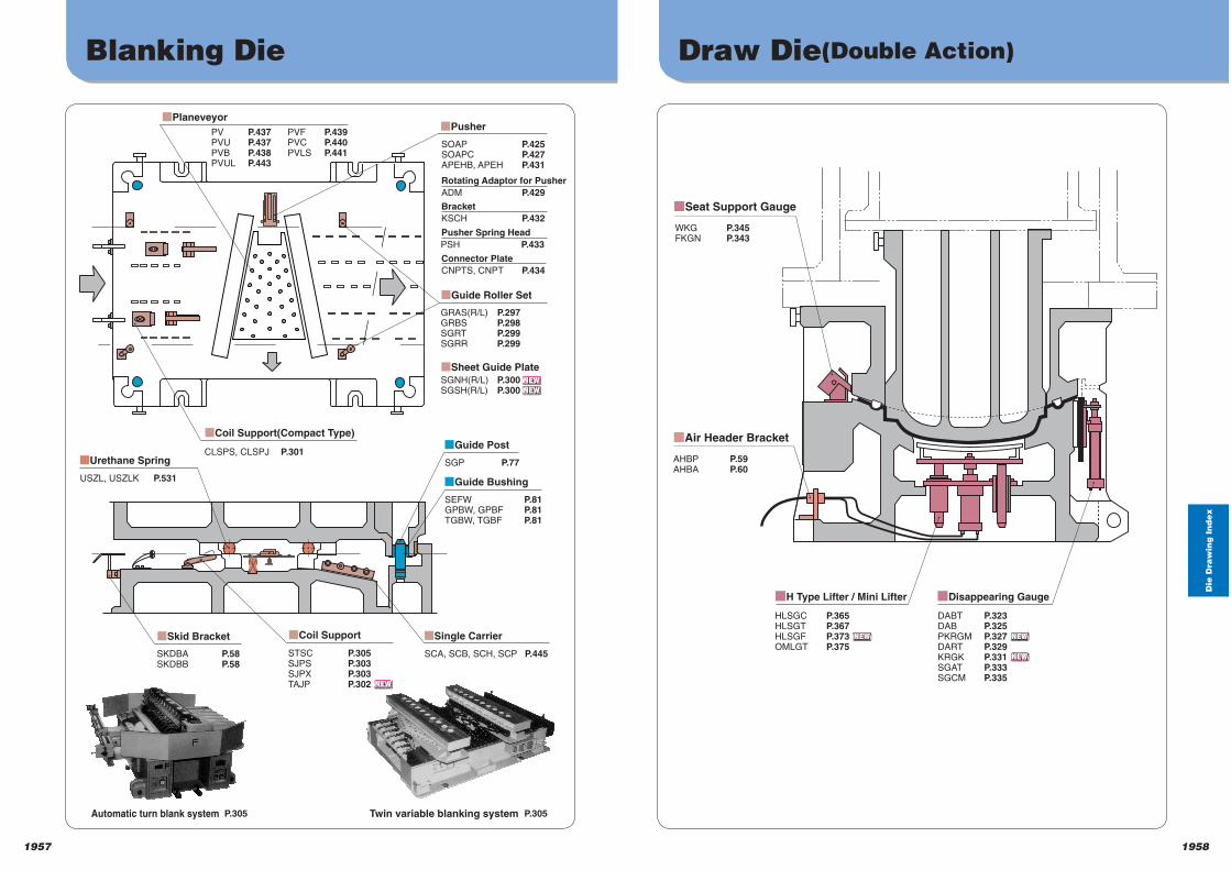
Die
Dra
win
g I
nd
ex
19581957
Blanking Die Draw Die(Double Action)
SEFW P.81
GPBW, GPBF P.81
TGBW, TGBF P.81
SGP P.77
USZL, USZLK P.531
CLSPS, CLSPJ P.301
STSC P.305SJPS P.303SJPX P.303TAJP P.302
SKDBA P.58SKDBB P.58
GRAS(R/L) P.297GRBS P.298SGRT P.299SGRR P.299
■Sheet Guide Plate
SGNH(R/L) P.300SGSH(R/L) P.300
■Pusher
■Guide Roller Set
■Coil Support■Skid Bracket
■Coil Support(Compact Type)
■Urethane Spring
■Guide Post
SCA, SCB, SCH, SCP P.445
■Single Carrier
■Guide Bushing
SOAP P.425SOAPC P.427APEHB, APEH P.431
ADM P.429
■Planeveyor
Rotating Adaptor for Pusher
KSCH P.432
Bracket
PSH P.433
Pusher Spring Head
CNPTS, CNPT P.434
Connector Plate
PV P.437PVU P.437PVB P.438PVUL P.443
PVF P.439PVC P.440PVLS P.441
■Seat Support Gauge
■Air Header Bracket
HLSGC P.365HLSGT P.367HLSGF P.373OMLGT P.375
WKG P.345FKGN P.343
AHBP P.59AHBA P.60
DABT P.323DAB P.325PKRGM P.327DART P.329KRGK P.331SGAT P.333SGCM P.335
■H Type Lifter / Mini Lifter ■Disappearing Gauge
Automatic turn blank system P.305 Twin variable blanking system P.305
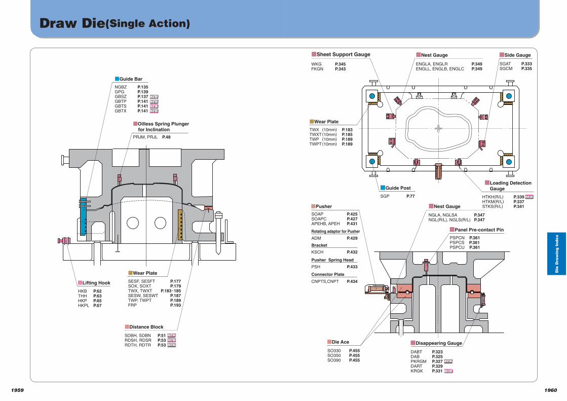
Die
Dra
win
g I
nd
ex
19601959
Draw Die(Single Action)
■Guide Bar
NGBZ P.135GPG P.139GBSZ P.137GBTP P.141GBTS P.141GBTX P.141
■Lifting Hook
HKB P.62THH P.63HKP P.65HKPL P.67
SDBH, SDBN P.51RDSH, RDSR P.53RDTH, RDTR P.53
SESF, SESFT P.177SOX, SOXT P.179TWX, TWXT P.183Y185SESW, SESWT P.187TWP, TWPT P.189FRP P.193
■Wear Plate
■Distance Block
PRJM, PRJL P.48
■Oilless Spring Plunger
for Inclination
■Nest Gauge
■Nest Gauge
■Sheet Support Gauge
WKG P.345FKGN P.343
■Wear Plate
TWX (10mm) P.183TWXT (10mm) P.185TWP (10mm) P.189TWPT (10mm) P.189
ENGLA, ENGLR P.349ENGLL, ENGLB, ENGLC P.349
■Pusher
SOAP P.425SOAPC P.427APEHB, APEH P.431
ADM P.429
Rotating adaptor for Pusher
KSCH P.432
Bracket
PSH P.433
Pusher Spring Head
CNPTS,CNPT P.434
Connector Plate
DABT P.323DAB P.325PKRGM P.327DART P.329KRGK P.331
■Disappearing Gauge
PSPCN P.361PSPCS P.361PSPCU P.361
■Panel Pre-contact Pin
SO330 P.455SO350 P.455SO390 P.455
■Die Ace
SGP P.77
■Guide Post
SGAT P.333SGCM P.335
■Side Gauge
HTKH(R/L) P.339HTKM(R/L) P.337STKS(R/L) P.341
NGLA, NGLSA P.347NGL(R/L), NGLS(R/L) P.347
■Loading Detection
Gauge
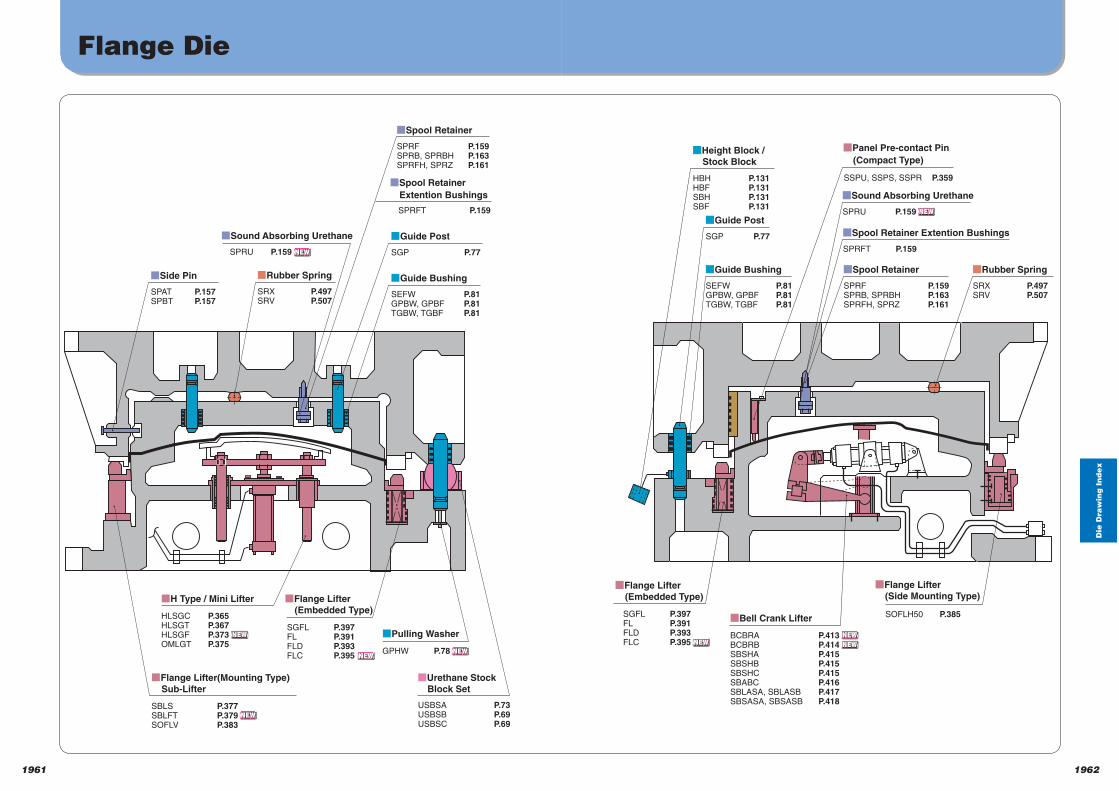
Die
Dra
win
g I
nd
ex
19621961
Flange Die
SPAT P.157SPBT P.157
qSide Pin
SEFW P.81GPBW, GPBF P.81TGBW, TGBF P.81
qGuide Bushing
SPRF P.159SPRB, SPRBH P.163SPRFH, SPRZ P.161
qSpool Retainer
SPRU P.159
qSound Absorbing Urethane
SPRFT P.159
qSpool Retainer
Extention Bushings
USBSA P.73USBSB P.69USBSC P.69
qUrethane Stock
Block Set
SGP P.77
qGuide Post
SRX P.497SRV P.507
qRubber Spring
HLSGC P.365HLSGT P.367HLSGF P.373OMLGT P.375
qH Type / Mini Lifter
GPHW P.78
qPulling WasherSGFL P.397FL P.391FLD P.393FLC P.395
qFlange Lifter
(Embedded Type)
SBLS P.377SBLFT P.379SOFLV P.383
qFlange Lifter(Mounting Type)
Sub-Lifter
SEFW P.81GPBW, GPBF P.81TGBW, TGBF P.81
■Guide Bushing
HBH P.131HBF P.131SBH P.131SBF P.131
■Height Block /
Stock Block
SGP P.77
■Guide Post
SSPU, SSPS, SSPR P.359
■Panel Pre-contact Pin
(Compact Type)
SRX P.497SRV P.507
■Rubber Spring
SPRF P.159SPRB, SPRBH P.163SPRFH, SPRZ P.161
■Spool Retainer
SPRFT P.159
■Spool Retainer Extention Bushings
SPRU P.159
■Sound Absorbing Urethane
BCBRA P.413BCBRB P.414SBSHA P.415SBSHB P.415SBSHC P.415SBABC P.416SBLASA, SBLASB P.417SBSASA, SBSASB P.418
■Bell Crank Lifter SOFLH50 P.385
■Flange Lifter
(Side Mounting Type)
SGFL P.397FL P.391FLD P.393FLC P.395
■Flange Lifter
(Embedded Type)
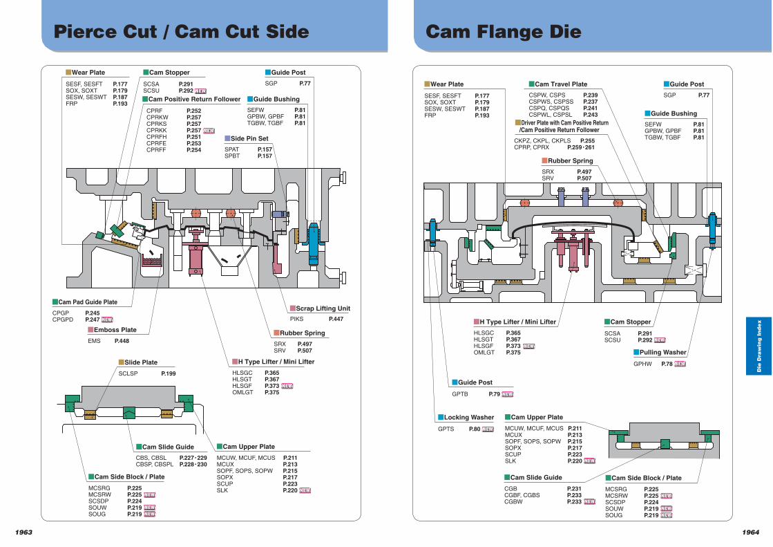
Die
Dra
win
g I
nd
ex
19641963
Pierce Cut / Cam Cut Side Cam Flange Die
MCSRG P.225
MCSRW P.225
SCSDP P.224
SOUW P.219
SOUG P.219
HLSGC P.365
HLSGT P.367
HLSGF P.373
OMLGT P.375
SESF, SESFT P.177SOX, SOXT P.179SESW, SESWT P.187FRP P.193
qWear Plate
SCSA P.291SCSU P.292
qCam Stopper
CPRF P.252CPRKW P.257CPRKS P.257CPRKK P.257CPRFH P.251CPRFE P.253CPRFF P.254
qCam Positive Return Follower
SGP P.77
qGuide Post
SEFW P.81GPBW, GPBF P.81TGBW, TGBF P.81
qGuide Bushing
SPAT P.157SPBT P.157
qSide Pin Set
CPGP P.245CPGPD P.247
■Cam Pad Guide Plate
EMS P.448
qEmboss Plate
qH Type Lifter / Mini Lifter
SRX P.497SRV P.507
■Rubber Spring
PIKS P.447
■Scrap Lifting Unit
SCLSP P.199
qSlide Plate
CBS, CBSL P.227Y229CBSP, CBSPL P.228Y230
■Cam Slide Guide
MCUW, MCUF, MCUS P.211MCUX P.213SOPF, SOPS, SOPW P.215SOPX P.217SCUP P.223SLK P.220
qCam Upper Plate
qCam Side Block / Plate
SGP P.77
qGuide Post
SEFW P.81GPBW, GPBF P.81TGBW, TGBF P.81
qGuide Bushing
CSPW, CSPS P.239CSPWS, CSPSS P.237CSPQ, CSPQS P.241CSPWL, CSPSL P.243
qCam Travel Plate
CKPZ, CKPL, CKPLS P.255CPRP, CPRX P.259Y261
■Driver Plate with Cam Positive Return /Cam Positive Return Follower
SRX P.497SRV P.507
qRubber Spring
SESF, SESFT P.177SOX, SOXT P.179SESW, SESWT P.187FRP P.193
qWear Plate
HLSGC P.365HLSGT P.367HLSGF P.373OMLGT P.375
qH Type Lifter / Mini Lifter
SCSA P.291SCSU P.292
qCam Stopper
GPTS P.80
qLocking Washer
GPTB P.79
qGuide Post
GPHW P.78
qPulling Washer
MCSRG P.225MCSRW P.225SCSDP P.224SOUW P.219SOUG P.219
qCam Side Block / Plate
MCUW, MCUF, MCUS P.211MCUX P.213SOPF, SOPS, SOPW P.215SOPX P.217SCUP P.223SLK P.220
qCam Upper Plate
CGB P.231CGBF, CGBS P.233CGBW P.233
qCam Slide Guide
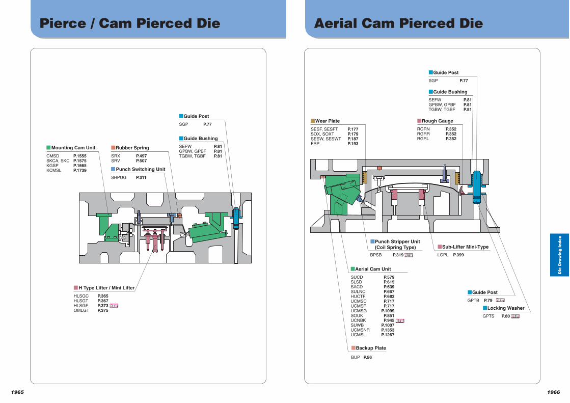
Die
Dra
win
g I
nd
ex
19661965
Pierce / Cam Pierced Die Aerial Cam Pierced Die
CMSD P.1555SKCA, SKC P.1575KGSP P.1665KCMSL P.1739
qMounting Cam Unit
SHPUG P.311
qPunch Switching Unit
SRX P.497SRV P.507
qRubber Spring
SGP P.77
qGuide Post
SEFW P.81GPBW, GPBF P.81TGBW, TGBF P.81
qGuide Bushing
HLSGC P.365HLSGT P.367HLSGF P.373OMLGT P.375
qH Type Lifter / Mini Lifter
RGRN P.352RGRR P.352RGRL P.352
qRough Gauge
qPunch Stripper Unit
(Coil Spring Type) qSub-Lifter Mini-Type
qBackup Plate
SGP P.77
qGuide Post
SEFW P.81GPBW, GPBF P.81TGBW, TGBF P.81
qGuide Bushing
SUCD P.579SLSD P.615SACD P.639SULNC P.667HUCTF P.683UCMSC P.717UCMSF P.717UCMSG P.1099SOUK P.851UCNBK P.945SUWB P.1007UCMSNR P.1353UCMSL P.1267
BUP P.56
BPSB P.319 LGPL P.399
qGuide Post
GPTB P.79
qLocking Washer
GPTS P.80
qAerial Cam Unit
SESF, SESFT P.177SOX, SOXT P.179SESW, SESWT P.187FRP P.193
qWear Plate
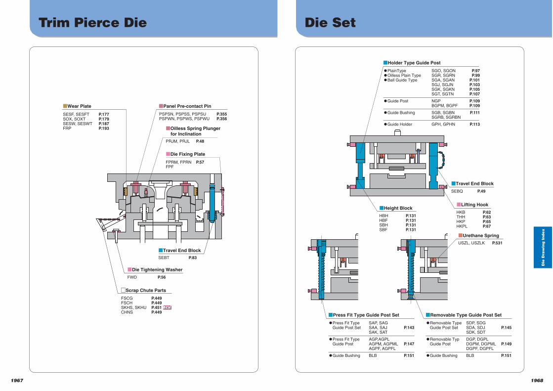
Die
Dra
win
g I
nd
ex
19681967
Trim Pierce Die Die Set
SESF, SESFT P.177SOX, SOXT P.179SESW, SESWT P.187FRP P.193
PRJM, PRJL P.48
FPRM, FPRN P.57FPF
FWD P.56
SEBT P.83
FSCG P.449FSCH P.449SKHS, SKHU P.451CHNS P.449
qWear Plate
qTravel End Block
qOilless Spring Plunger
for Inclination
qDie Fixing Plate
■Scrap Chute Parts
qDie Tightening Washer
PSPSN, PSPSS, PSPSU P.355PSPWN, PSPWS, PSPWU P.356
qPanel Pre-contact Pin
UPlainType SGO, SGON P.97 UOilless Plain Type SGR, SGRN P.99 UBall Guide Type SGA, SGAN P.101 SGJ, SGJN P.103 SGK, SGKN P.105 SGT, SGTN P.107
UGuide Post NGP P.109 BGPM, BGPF P.109
UGuide Bushing SGB, SGBN P.111 SGRB, SGRBN
UGuide Holder GPH, GPHN P.113
qHolder Type Guide Post
URemovable Type SDP, SDG Guide Post Set SDA, SDJ P.145 SDK, SDT
URemovable Typ DGP, DGPL Guide Post DGPM, DGPML P.149 DGPF, DGPFL
UGuide Bushing BLB P.151
qRemovable Type Guide Post Set
UPress Fit Type SAP, SAG Guide Post Set SAA, SAJ P.143 SAK, SAT
UPress Fit Type AGP,AGPL Guide Post AGPM, AGPML P.147 AGPF, AGPFL
UGuide Bushing BLB P.151
qPress Fit Type Guide Post Set
qTravel End Block
qHeight Block
qUrethane Spring
SEBQ P.49
HBH P.131HBF P.131SBH P.131SBF P.131
qLifting Hook
HKB P.62THH P.63HKP P.65HKPL P.67
USZL, USZLK P.531
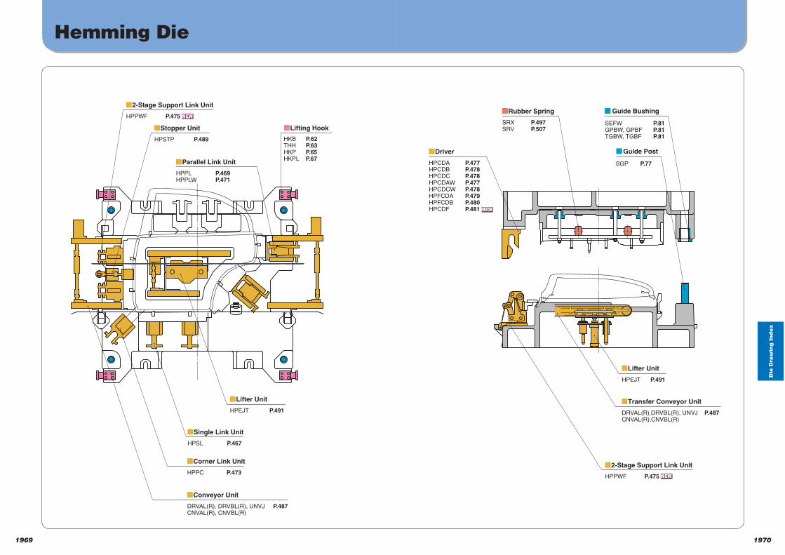
Die
Dra
win
g I
nd
ex
19701969
Hemming Die
HPSTP P.489
qStopper Unit
HPPWF P.475
q2-Stage Support Link Unit
HPPL P.469HPPLW P.471
qParallel Link Unit
HPEJT P.491
qLifter Unit
HPSL P.467
qSingle Link Unit
HPPC P.473
qCorner Link Unit
DRVAL(R), DRVBL(R), UNVJ P.487CNVAL(R), CNVBL(R)
qConveyor Unit
qLifting Hook
HKB P.62THH P.63HKP P.65HKPL P.67
Guide Bushing
SEFW P.81GPBW, GPBF P.81TGBW, TGBF P.81
Guide Post
SGP P.77
SRX P.497SRV P.507
■Rubber Spring
HPCDA P.477HPCDB P.478HPCDC P.478HPCDAW P.477HPCDCW P.478HPFCDA P.479HPFCDB P.480HPCDF P.481
■Driver
HPEJT P.491
qLifter Unit
DRVAL(R),DRVBL(R), UNVJ P.487CNVAL(R),CNVBL(R)
qTransfer Conveyor Unit
HPPWF P.475
q2-Stage Support Link Unit
1972
Ca
talo
g N
o. In
de
x
Catalog No.Index
Catalog No.Index
お取り引きにあたってCatalog No.Index
In ALPHABETICAL ………………………………………………………… P.1973 to 1978
1971
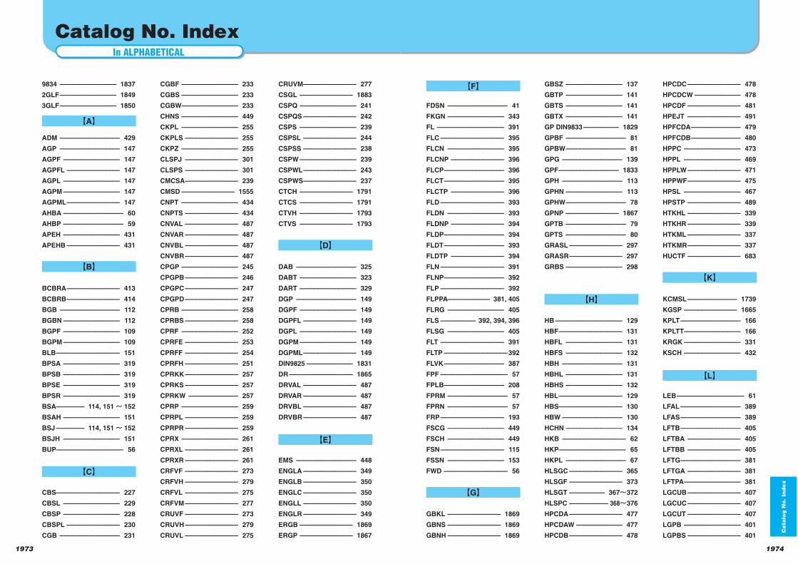
In ALPHABETICAL
Catalog No. Index
Ca
talo
g N
o. In
de
x
1974
HPCDC ––––––––––––––– 478
HPCDCW ––––––––––––– 478
HPCDF ––––––––––––––– 481
HPEJT ––––––––––––––– 491
HPFCDA –––––––––––––– 479
HPFCDB –––––––––––––– 480
HPPC –––––––––––––––– 473
HPPL –––––––––––––––– 469
HPPLW ––––––––––––––– 471
HPPWF ––––––––––––––– 475
HPSL –––––––––––––––– 467
HPSTP ––––––––––––––– 489
HTKHL ––––––––––––––– 339
HTKHR ––––––––––––––– 339
HTKML ––––––––––––––– 337
HTKMR ––––––––––––––– 337
HUCTF ––––––––––––––– 683
KCMSL –––––––––––––– 1739
KGSP ––––––––––––––– 1665
KPLT ––––––––––––––––– 166
KPLTT –––––––––––––––– 166
KRGK –––––––––––––––– 331
KSCH –––––––––––––––– 432
LEB ––––––––––––––––––– 61
LFAL ––––––––––––––––– 389
LFAS ––––––––––––––––– 389
LFTB ––––––––––––––––– 405
LFTBA ––––––––––––––– 405
LFTBB ––––––––––––––– 405
LFTG ––––––––––––––––– 381
LFTGA ––––––––––––––– 381
LFTPA –––––––––––––––– 381
LGCUB ––––––––––––––– 407
LGCUC ––––––––––––––– 407
LGCUT ––––––––––––––– 407
LGPB –––––––––––––––– 401
LGPBS ––––––––––––––– 401
GBSZ –––––––––––––––– 137
GBTP –––––––––––––––– 141
GBTS –––––––––––––––– 141
GBTX –––––––––––––––– 141
GP DIN9833 –––––––––– 1829
GPBF ––––––––––––––––– 81
GPBW ––––––––––––––––– 81
GPG ––––––––––––––––– 139
GPF ––––––––––––––––– 1833
GPH ––––––––––––––––– 113
GPHN –––––––––––––––– 113
GPHW ––––––––––––––––– 78
GPNP ––––––––––––––– 1867
GPTB ––––––––––––––––– 79
GPTS ––––––––––––––––– 80
GRASL ––––––––––––––– 297
GRASR ––––––––––––––– 297
GRBS –––––––––––––––– 298
HB ––––––––––––––––––– 129
HBF –––––––––––––––––– 131
HBFL –––––––––––––––– 131
HBFS –––––––––––––––– 132
HBH ––––––––––––––––– 131
HBHL –––––––––––––––– 131
HBHS –––––––––––––––– 132
HBL –––––––––––––––––– 129
HBS–––––––––––––––––– 130
HBW ––––––––––––––––– 130
HCHN –––––––––––––––– 134
HKB –––––––––––––––––– 62
HKP ––––––––––––––––––– 65
HKPL ––––––––––––––––– 67
HLSGC ––––––––––––––– 365
HLSGF ––––––––––––––– 373
HLSGT –––––––––– 367 372
HLSPC ––––––––––– 368 376
HPCDA ––––––––––––––– 477
HPCDAW ––––––––––––– 477
HPCDB ––––––––––––––– 478
FDSN ––––––––––––––––– 41
FKGN –––––––––––––––– 343
FL ––––––––––––––––––– 391
FLC –––––––––––––––––– 395
FLCN –––––––––––––––– 395
FLCNP ––––––––––––––– 396
FLCP ––––––––––––––––– 396
FLCT ––––––––––––––––– 395
FLCTP ––––––––––––––– 396
FLD –––––––––––––––––– 393
FLDN –––––––––––––––– 393
FLDNP ––––––––––––––– 394
FLDP ––––––––––––––––– 394
FLDT ––––––––––––––––– 393
FLDTP ––––––––––––––– 394
FLN –––––––––––––––––– 391
FLNP ––––––––––––––––– 392
FLP –––––––––––––––––– 392
FLPPA–––––––––––– 381, 405
FLRG –––––––––––––––– 405
FLS –––––––––– 392, 394, 396
FLSG –––––––––––––––– 405
FLT –––––––––––––––––– 391
FLTP ––––––––––––––––––392
FLVK ––––––––––––––––– 387
FPF ––––––––––––––––––– 57
FPLB ––––––––––––––––– 208
FPRM ––––––––––––––––– 57
FPRN ––––––––––––––––– 57
FRP –––––––––––––––––– 193
FSCG –––––––––––––––– 449
FSCH –––––––––––––––– 449
FSN –––––––––––––––––– 115
FSSN –––––––––––––––– 153
FWD –––––––––––––––––– 56
GBKL ––––––––––––––– 1869
GBNS ––––––––––––––– 1869
GBNH ––––––––––––––– 1869
9834 –––––––––––––––– 1837
2GLF –––––––––––––––– 1849
3GLF –––––––––––––––– 1850
ADM ––––––––––––––––– 429
AGP ––––––––––––––––– 147
AGPF –––––––––––––––– 147
AGPFL ––––––––––––––– 147
AGPL –––––––––––––––– 147
AGPM –––––––––––––––– 147
AGPML ––––––––––––––– 147
AHBA ––––––––––––––––– 60
AHBP ––––––––––––––––– 59
APEH –––––––––––––––– 431
APEHB ––––––––––––––– 431
BCBRA ––––––––––––––– 413
BCBRB ––––––––––––––– 414
BGB ––––––––––––––––– 112
BGBN –––––––––––––––– 112
BGPF –––––––––––––––– 109
BGPM –––––––––––––––– 109
BLB –––––––––––––––––– 151
BPSA –––––––––––––––– 319
BPSB –––––––––––––––– 319
BPSE –––––––––––––––– 319
BPSR –––––––––––––––– 319
BSA –––––––– 114, 151~ 152
BSAH –––––––––––––––– 151
BSJ –––––––– 114, 151~ 152
BSJH –––––––––––––––– 151
BUP ––––––––––––––––––– 56
CBS–––––––––––––––––– 227
CBSL –––––––––––––––– 229
CBSP –––––––––––––––– 228
CBSPL ––––––––––––––– 230
CGB ––––––––––––––––– 231
CRUVM ––––––––––––––– 277
CSGL ––––––––––––––– 1883
CSPQ –––––––––––––––– 241
CSPQS ––––––––––––––– 242
CSPS –––––––––––––––– 239
CSPSL ––––––––––––––– 244
CSPSS ––––––––––––––– 238
CSPW –––––––––––––––– 239
CSPWL ––––––––––––––– 243
CSPWS ––––––––––––––– 237
CTCH ––––––––––––––– 1791
CTCS ––––––––––––––– 1791
CTVH ––––––––––––––– 1793
CTVS ––––––––––––––– 1793
DAB ––––––––––––––––– 325
DABT –––––––––––––––– 323
DART –––––––––––––––– 329
DGP ––––––––––––––––– 149
DGPF –––––––––––––––– 149
DGPFL ––––––––––––––– 149
DGPL –––––––––––––––– 149
DGPM –––––––––––––––– 149
DGPML ––––––––––––––– 149
DIN9825 ––––––––––––– 1831
DR –––––––––––––––––– 1865
DRVAL ––––––––––––––– 487
DRVAR ––––––––––––––– 487
DRVBL ––––––––––––––– 487
DRVBR ––––––––––––––– 487
EMS ––––––––––––––––– 448
ENGLA ––––––––––––––– 349
ENGLB ––––––––––––––– 350
ENGLC ––––––––––––––– 350
ENGLL ––––––––––––––– 350
ENGLR ––––––––––––––– 349
ERGB ––––––––––––––– 1869
ERGP ––––––––––––––– 1867
CGBF –––––––––––––––– 233
CGBS –––––––––––––––– 233
CGBW–––––––––––––––– 233
CHNS –––––––––––––––– 449
CKPL –––––––––––––––– 255
CKPLS ––––––––––––––– 255
CKPZ –––––––––––––––– 255
CLSPJ ––––––––––––––– 301
CLSPS ––––––––––––––– 301
CMCSA ––––––––––––––– 239
CMSD ––––––––––––––– 1555
CNPT –––––––––––––––– 434
CNPTS ––––––––––––––– 434
CNVAL ––––––––––––––– 487
CNVAR ––––––––––––––– 487
CNVBL ––––––––––––––– 487
CNVBR ––––––––––––––– 487
CPGP –––––––––––––––– 245
CPGPB ––––––––––––––– 246
CPGPC ––––––––––––––– 247
CPGPD ––––––––––––––– 247
CPRB –––––––––––––––– 258
CPRBS ––––––––––––––– 258
CPRF –––––––––––––––– 252
CPRFE ––––––––––––––– 253
CPRFF ––––––––––––––– 254
CPRFH ––––––––––––––– 251
CPRKK ––––––––––––––– 257
CPRKS ––––––––––––––– 257
CPRKW –––––––––––––– 257
CPRP –––––––––––––––– 259
CPRPL ––––––––––––––– 259
CPRPR ––––––––––––––– 259
CPRX –––––––––––––––– 261
CPRXL ––––––––––––––– 261
CPRXR ––––––––––––––– 261
CRFVF ––––––––––––––– 273
CRFVH ––––––––––––––– 279
CRFVL ––––––––––––––– 275
CRFVM ––––––––––––––– 277
CRUVF ––––––––––––––– 273
CRUVH ––––––––––––––– 279
CRUVL ––––––––––––––– 275
1973
【A】
【B】
【C】
【D】
【F】
【E】
【G】
【H】
【K】
【L】
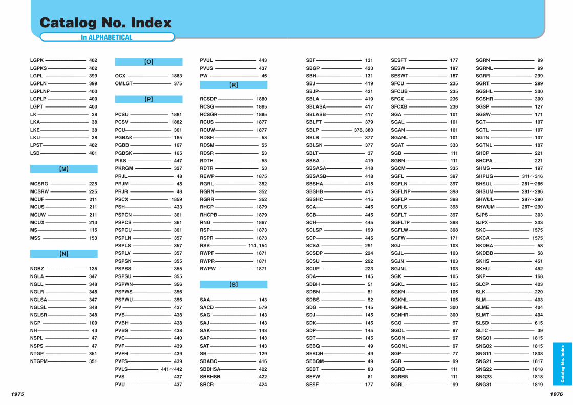
In ALPHABETICAL
Catalog No. Index
Ca
talo
g N
o. In
de
x
19761975
SBF –––––––––––––––––– 131
SBGP –––––––––––––––– 423
SBH–––––––––––––––––– 131
SBJ –––––––––––––––––– 419
SBJP ––––––––––––––––– 421
SBLA –––––––––––––––– 419
SBLASA –––––––––––––– 417
SBLASB –––––––––––––– 417
SBLFT ––––––––––––––– 379
SBLP –––––––––––– 378, 380
SBLS –––––––––––––––– 377
SBLSN ––––––––––––––– 377
SBLT –––––––––––––––––– 37
SBSA –––––––––––––––– 419
SBSASA –––––––––––––– 418
SBSASB –––––––––––––– 418
SBSHA ––––––––––––––– 415
SBSHB ––––––––––––––– 415
SBSHC ––––––––––––––– 415
SCA –––––––––––––––––– 445
SCB–––––––––––––––––– 445
SCH–––––––––––––––––– 445
SCLSP ––––––––––––––– 199
SCP –––––––––––––––––– 445
SCSA –––––––––––––––– 291
SCSDP ––––––––––––––– 224
SCSU –––––––––––––––– 292
SCUP –––––––––––––––– 223
SDA –––––––––––––––––– 145
SDBH ––––––––––––––––– 51
SDBN ––––––––––––––––– 51
SDBS ––––––––––––––––– 52
SDG ––––––––––––––––– 145
SDJ –––––––––––––––––– 145
SDK–––––––––––––––––– 145
SDP –––––––––––––––––– 145
SDT –––––––––––––––––– 145
SEBQ ––––––––––––––––– 49
SEBQH –––––––––––––––– 49
SEBQM –––––––––––––––– 49
SEBT ––––––––––––––––– 83
SEFW ––––––––––––––––– 81
SESF ––––––––––––––––– 177
PVUL –––––––––––––––– 443
PVUS –––––––––––––––– 437
PW ––––––––––––––––––– 46
RCSDP –––––––––––––– 1880
RCSG ––––––––––––––– 1885
RCSGR –––––––––––––– 1885
RCUS ––––––––––––––– 1877
RCUW ––––––––––––––– 1877
RDSH ––––––––––––––––– 53
RDSM ––––––––––––––––– 55
RDSR ––––––––––––––––– 53
RDTH ––––––––––––––––– 53
RDTR ––––––––––––––––– 53
REWP ––––––––––––––– 1875
RGRL –––––––––––––––– 352
RGRN –––––––––––––––– 352
RGRR –––––––––––––––– 352
RHCP ––––––––––––––– 1879
RHCPB –––––––––––––– 1879
RNG –––––––––––––––– 1867
RSP ––––––––––––––––– 1873
RSPR ––––––––––––––– 1873
RSS –––––––––––––– 114, 154
RWPF ––––––––––––––– 1871
RWPR ––––––––––––––– 1871
RWPW –––––––––––––– 1871
SAA –––––––––––––––––– 143
SACD –––––––––––––––– 579
SAG ––––––––––––––––– 143
SAJ –––––––––––––––––– 143
SAK–––––––––––––––––– 143
SAP –––––––––––––––––– 143
SAT –––––––––––––––––– 143
SB ––––––––––––––––––– 129
SBABC ––––––––––––––– 416
SBBHSA –––––––––––––– 422
SBBHSB–––––––––––––– 422
SBCR –––––––––––––––– 424
SGRN ––––––––––––––––– 99
SGRNL –––––––––––––––– 99
SGRR –––––––––––––––– 299
SGRT –––––––––––––––– 299
SGSHL ––––––––––––––– 300
SGSHR ––––––––––––––– 300
SGSP –––––––––––––––– 127
SGSW –––––––––––––––– 171
SGT –––––––––––––––––– 107
SGTL –––––––––––––––– 107
SGTN –––––––––––––––– 107
SGTNL ––––––––––––––– 107
SHCP –––––––––––––––– 221
SHCPA ––––––––––––––– 221
SHMS –––––––––––––––– 197
SHPUG –––––––––– 311 316
SHSUL –––––––––– 281 286
SHSUM –––––––––– 281 286
SHWUL –––––––––– 287 290
SHWUM ––––––––– 287 290
SJPS ––––––––––––––––– 303
SJPX ––––––––––––––––– 303
SKC––––––––––––––––– 1575
SKCA ––––––––––––––– 1575
SKDBA –––––––––––––––– 58
SKDBB –––––––––––––––– 58
SKHS –––––––––––––––– 451
SKHU –––––––––––––––– 452
SKP –––––––––––––––––– 168
SLCP –––––––––––––––– 403
SLK –––––––––––––––––– 220
SLM–––––––––––––––––– 403
SLME –––––––––––––––– 404
SLMT –––––––––––––––– 404
SLSD –––––––––––––––– 615
SLTC –––––––––––––––––– 39
SNG01 –––––––––––––– 1815
SNG02 –––––––––––––– 1815
SNG11 –––––––––––––– 1808
SNG21 –––––––––––––– 1817
SNG22 –––––––––––––– 1818
SNG23 –––––––––––––– 1818
SNG31 –––––––––––––– 1819
SESFT ––––––––––––––– 177
SESW –––––––––––––––– 187
SESWT ––––––––––––––– 187
SFCU –––––––––––––––– 235
SFCUB ––––––––––––––– 235
SFCX –––––––––––––––– 236
SFCXB ––––––––––––––– 236
SGA ––––––––––––––––– 101
SGAL –––––––––––––––– 101
SGAN –––––––––––––––– 101
SGANL ––––––––––––––– 101
SGAT –––––––––––––––– 333
SGB ––––––––––––––––– 111
SGBN –––––––––––––––– 111
SGCM –––––––––––––––– 335
SGFL –––––––––––––––– 397
SGFLN ––––––––––––––– 397
SGFLNP –––––––––––––– 398
SGFLP ––––––––––––––– 398
SGFLS ––––––––––––––– 398
SGFLT ––––––––––––––– 397
SGFLTP –––––––––––––– 398
SGFLW ––––––––––––––– 398
SGFW –––––––––––––––– 171
SGJ –––––––––––––––––– 103
SGJL ––––––––––––––––– 103
SGJN –––––––––––––––– 103
SGJNL ––––––––––––––– 103
SGK ––––––––––––––––– 105
SGKL –––––––––––––––– 105
SGKN –––––––––––––––– 105
SGKNL ––––––––––––––– 105
SGNHL ––––––––––––––– 300
SGNHR ––––––––––––––– 300
SGO –––––––––––––––––– 97
SGOL ––––––––––––––––– 97
SGON ––––––––––––––––– 97
SGONL –––––––––––––––– 97
SGP ––––––––––––––––––– 77
SGR –––––––––––––––––– 99
SGRB –––––––––––––––– 111
SGRBN ––––––––––––––– 111
SGRL ––––––––––––––––– 99
LGPK –––––––––––––––– 402
LGPKS ––––––––––––––– 402
LGPL –––––––––––––––– 399
LGPLN ––––––––––––––– 399
LGPLNP –––––––––––––– 400
LGPLP ––––––––––––––– 400
LGPT –––––––––––––––– 400
LK –––––––––––––––––––– 38
LKA ––––––––––––––––––– 38
LKE ––––––––––––––––––– 38
LKU ––––––––––––––––––– 38
LPST ––––––––––––––––– 402
LSB –––––––––––––––––– 401
MCSRG –––––––––––––– 225
MCSRW –––––––––––––– 225
MCUF –––––––––––––––– 211
MCUS –––––––––––––––– 211
MCUW ––––––––––––––– 211
MCUX –––––––––––––––– 213
MS ––––––––––––––––––– 115
MSS ––––––––––––––––– 153
NGBZ –––––––––––––––– 135
NGLA –––––––––––––––– 347
NGLL –––––––––––––––– 348
NGLR –––––––––––––––– 348
NGLSA ––––––––––––––– 347
NGLSL ––––––––––––––– 348
NGLSR ––––––––––––––– 348
NGP ––––––––––––––––– 109
NH –––––––––––––––––––– 43
NSPL ––––––––––––––––– 47
NSPS ––––––––––––––––– 47
NTGP –––––––––––––––– 351
NTGPM ––––––––––––––– 351
OCX –––––––––––––––– 1863
OMLGT ––––––––––––––– 375
PCSU ––––––––––––––– 1881
PCSV ––––––––––––––– 1882
PCU–––––––––––––––––– 361
PGBAK ––––––––––––––– 165
PGBB –––––––––––––––– 167
PGBSK ––––––––––––––– 165
PIKS ––––––––––––––––– 447
PKRGM –––––––––––––– 327
PRJL –––––––––––––––––– 48
PRJM ––––––––––––––––– 48
PRJR ––––––––––––––––– 48
PSCX ––––––––––––––– 1859
PSH –––––––––––––––––– 433
PSPCN ––––––––––––––– 361
PSPCS ––––––––––––––– 361
PSPCU ––––––––––––––– 361
PSPLN ––––––––––––––– 357
PSPLS ––––––––––––––– 357
PSPLV ––––––––––––––– 357
PSPSN ––––––––––––––– 355
PSPSS ––––––––––––––– 355
PSPSU ––––––––––––––– 355
PSPWN ––––––––––––––– 356
PSPWS ––––––––––––––– 356
PSPWU ––––––––––––––– 356
PV ––––––––––––––––––– 437
PVB –––––––––––––––––– 438
PVBH –––––––––––––––– 438
PVBS –––––––––––––––– 438
PVC –––––––––––––––––– 440
PVF –––––––––––––––––– 439
PVFH –––––––––––––––– 439
PVFS ––––––––––––––––– 439
PVLS –––––––––––– 441 442
PVS –––––––––––––––––– 437
PVU –––––––––––––––––– 437
【O】
【P】
【R】
【S】
【M】
【N】
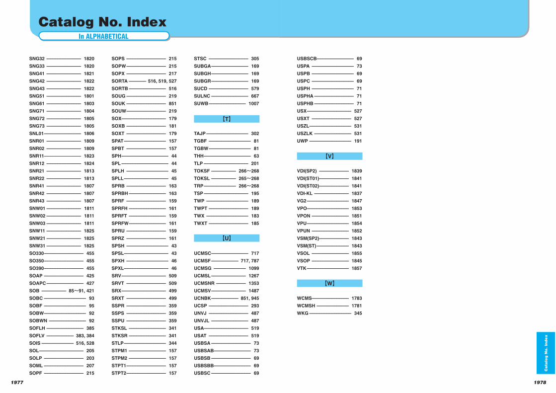
In ALPHABETICAL索 引
Catalog No. Index
USBSCB––––––––––––––– 69
USPA ––––––––––––––––– 73
USPB ––––––––––––––––– 69
USPC ––––––––––––––––– 69
USPH ––––––––––––––––– 71
USPHA –––––––––––––––– 71
USPHB –––––––––––––––– 71
USX –––––––––––––––––– 527
USXT –––––––––––––––– 527
USZL ––––––––––––––––– 531
USZLK ––––––––––––––– 531
UWP ––––––––––––––––– 191
VDI(SP2) –––––––––––– 1839
VDI(ST01) –––––––––––– 1841
VDI(ST02) –––––––––––– 1841
VDI-KL –––––––––––––– 1837
VG2 ––––––––––––––––– 1847
VPO––––––––––––––––– 1853
VPON ––––––––––––––– 1851
VPU ––––––––––––––––– 1854
VPUN ––––––––––––––– 1852
VSM(SP2) –––––––––––– 1843
VSM(ST) ––––––––––––– 1843
VSOL ––––––––––––––– 1855
VSOP ––––––––––––––– 1845
VTK ––––––––––––––––– 1857
WCMS––––––––––––––– 1783
WCMSH ––––––––––––– 1781
WKG ––––––––––––––––– 345
1978
Ca
talo
g N
o. In
de
x
SNG32 –––––––––––––– 1820
SNG33 –––––––––––––– 1820
SNG41 –––––––––––––– 1821
SNG42 –––––––––––––– 1822
SNG43 –––––––––––––– 1822
SNG51 –––––––––––––– 1801
SNG61 –––––––––––––– 1803
SNG71 –––––––––––––– 1804
SNG72 –––––––––––––– 1805
SNG73 –––––––––––––– 1805
SNL01 ––––––––––––––– 1806
SNR01 –––––––––––––– 1809
SNR02 –––––––––––––– 1809
SNR11––––––––––––––– 1823
SNR12 –––––––––––––– 1824
SNR21 –––––––––––––– 1813
SNR22 –––––––––––––– 1813
SNR41 –––––––––––––– 1807
SNR42 –––––––––––––– 1807
SNR43 –––––––––––––– 1807
SNW01 –––––––––––––– 1811
SNW02 –––––––––––––– 1811
SNW03 –––––––––––––– 1811
SNW11 –––––––––––––– 1825
SNW21 –––––––––––––– 1825
SNW31 –––––––––––––– 1825
SO330 –––––––––––––––– 455
SO350 –––––––––––––––– 455
SO390 –––––––––––––––– 455
SOAP –––––––––––––––– 425
SOAPC ––––––––––––––– 427
SOB –––––––––– 85 91, 421
SOBC ––––––––––––––––– 93
SOBF ––––––––––––––––– 95
SOBW ––––––––––––––––– 92
SOBWN ––––––––––––––– 92
SOFLH ––––––––––––––– 385
SOFLV ––––––––––– 383, 384
SOIS ––––––––––––– 516, 528
SOL –––––––––––––––––– 205
SOLP –––––––––––––––– 203
SOML –––––––––––––––– 207
SOPF –––––––––––––––– 215
STSC –––––––––––––––– 305
SUBGA ––––––––––––––– 169
SUBGH ––––––––––––––– 169
SUBGR ––––––––––––––– 169
SUCD –––––––––––––––– 579
SULNC ––––––––––––––– 667
SUWB ––––––––––––––– 1007
TAJP ––––––––––––––––– 302
TGBF ––––––––––––––––– 81
TGBW ––––––––––––––––– 81
THH ––––––––––––––––––– 63
TLP –––––––––––––––––– 201
TOKSF –––––––––– 266 268
TOKSL –––––––––– 265 268
TRP ––––––––––––– 266 268
TSP –––––––––––––––––– 195
TWP ––––––––––––––––– 189
TWPT –––––––––––––––– 189
TWX ––––––––––––––––– 183
TWXT –––––––––––––––– 185
UCMSC ––––––––––––––– 717
UCMSF ––––––––––– 717, 787
UCMSG ––––––––––––– 1099
UCMSL –––––––––––––– 1267
UCMSNR –––––––––––– 1353
UCMSV –––––––––––––– 1487
UCNBK ––––––––––– 851, 945
UCSP –––––––––––––––– 293
UNVJ –––––––––––––––– 487
UNVJL ––––––––––––––– 487
USA –––––––––––––––––– 519
USAT –––––––––––––––– 519
USBSA –––––––––––––––– 73
USBSAB––––––––––––––– 73
USBSB –––––––––––––––– 69
USBSBB––––––––––––––– 69
USBSC –––––––––––––––– 69
SOPS –––––––––––––––– 215
SOPW –––––––––––––––– 215
SOPX –––––––––––––––– 217
SORTA ––––––– 516, 519, 527
SORTB ––––––––––––––– 516
SOUG –––––––––––––––– 219
SOUK –––––––––––––––– 851
SOUW –––––––––––––––– 219
SOX–––––––––––––––––– 179
SOXB –––––––––––––––– 181
SOXT –––––––––––––––– 179
SPAT ––––––––––––––––– 157
SPBT –––––––––––––––– 157
SPH ––––––––––––––––––– 44
SPL ––––––––––––––––––– 44
SPLH ––––––––––––––––– 45
SPLL –––––––––––––––––– 45
SPRB –––––––––––––––– 163
SPRBH ––––––––––––––– 163
SPRF –––––––––––––––– 159
SPRFH ––––––––––––––– 161
SPRFT ––––––––––––––– 159
SPRFW ––––––––––––––– 161
SPRU –––––––––––––––– 159
SPRZ –––––––––––––––– 161
SPSH ––––––––––––––––– 43
SPSL –––––––––––––––––– 43
SPXH ––––––––––––––––– 46
SPXL –––––––––––––––––– 46
SRV –––––––––––––––––– 509
SRVT –––––––––––––––– 509
SRX –––––––––––––––––– 499
SRXT –––––––––––––––– 499
SSPR –––––––––––––––– 359
SSPS –––––––––––––––– 359
SSPU –––––––––––––––– 359
STKSL ––––––––––––––– 341
STKSR ––––––––––––––– 341
STLP ––––––––––––––––– 344
STPM1 ––––––––––––––– 157
STPM2 ––––––––––––––– 157
STPT1 –––––––––––––––– 157
STPT2 –––––––––––––––– 157
1977
【T】
【U】
【W】
【V】

Standard Components for Plastic Moulds 2007 Available on request(free)
Standard parts mainly for large plastic
moulds are now available.
Die Setting ComponentsLifting Hook,Locating Block, etc
Die Guide Related PartsGuide pin,Assist Pin,Guide bushing, etc
Ejector Related PartsEjector Guide Pin,Ejector Guide Bushing, etc
Loose Core Related PartsSlide Unit for Loose Core,Inclined Pin,Spherical Guide
Bushing Set for Inclined Pin,etc
Slide Core Related PartsSlide Core Unit,Locking Block,Angular Pin,Guide
Rail,etc
Slide PlateVarious slide plates
Standard Components for Sliding Material 2008 Available on request(free)
28 oilless sliding materials and standard
parts using these materials are listed. In
particular, metallic sliding materials are
produced from casting. We are meeting
various requirements of customers.
Sliding materials
Metal sliding materials ……15 materials
Resin sliding materials ……10 materials
Graphite sliding materials …… 3 materials
Standard sliding parts
About 50 items including metallic and plastic
parts are listed.
If you want our catalog,
please contact the nearest sales
office. Or request the catalog
from Sankyo's web site.
Blanking Die System
The blanking die system makes the
rectangle,parallelogram and trapezoid
shape blank dies
DIC.621
データY
2007
SANKYO OILLESS INDUSTRY, INC.
Standard Componentsfor Plastic Mold
for Sliding Material
Standard Components
Standard Components for Sliding Material
Double variable blanking
die system
Turn blanking die
system
Edited and issued by
1-1-5 Nisshin-cho, Fuchu, Tokyo
TEL.042-336-9602 FAX.042-368-3170
First edition: May, 2009 No copies allowed.
CopyrightAll copyrights including texts, photos, figures, materials, data, etc. shown on this catalog belong to Sankyo Oilless Industry, Inc. Any duplication, reprinting, citation, editing, translation, adaptation, publication, reselling, design, manufacture, sale of competitive products, etc. shall be "violation of the Copyright Law". We may take it to legal proceedings as "violation of the copyright".
For better service
For better quality
Together with customers