Embed Size (px)
Citation preview
UNCLASSIFIED
NACA CA·SE FILE
COpy
Copy E7 RM L52E05a
RESEARCH MEMORANDU M Classification Changed to
UNCLASSIFIED AlIj'hority
DOD DIR. 5200.10
APR ft'966 By
~~~rnATIcmN.~D~ev~efflreu~~ FLOW SEPARATION FROM RODS A
NOSES AT MACH NUMBER 2.72
By Jim J. Jones
Langley Aeronautical Laboratory Langley Field, Va.
I JUL 21 1952
NATIONAL ADVISORY COMMITTEE FOR AERONAUTICS
WASHINGTON
July 15, 1952
UNCLASSIFIED
https://ntrs.nasa.gov/search.jsp?R=19930087040 2018-06-16T18:24:22+00:00Z

lZ
UNCLASSIFIED NACA RM L52E05a
NATIONAL ADVISORY COMMITTEE FOR AERONAUTICS
RESEARCH MEMORANDUM
FLOW SEPARATION FROM RODS AHEAD OF BLUNT
NOSES AT MACH NUMBER 2. 71_-;:;-::-:-=-:;::-;:---:::::-_~ __ ~ Classification Changed to
By Jim J . J one s
SUMMARY
UNCLASSIFIED A~thority -----I
DOD DIR. 5200.10
APR p~e1966 By N. Devereux!
An experimental investigation in the Langley gas dynamics laborator has been made of the flow separ ation f r om slender rods mounted to extend ' forward along the axes of symmetry of blunt - nosed bodies. The mechanism of the separation and its governing criteria are discussed. Drag data at a Mach number of 2. 72 for various rod lengths and nose radii at an angle of attack of 00 are presented .
It was found that the drag coefficients of blunt noses could be appreciably reduced by the use of protruding rods. Criteria for rod length which gives lowest drag are given .
INTRODUCTION
The desirability of a blunt, rounded nose on a supersonic missile which contains a seeker device is well-known, and a number of investigations have been made of the r esultant drag increase. (See, for instance, refs. 1 to 3.) A study of noses in which the tip of a basic ogive is replaced by a near - hemisphere indicates that if the nose radius is less than one-quarter of the maximum radius of the body, the drag increase is not severe. With increasing nose radius, however, the drag increases very rapidly.
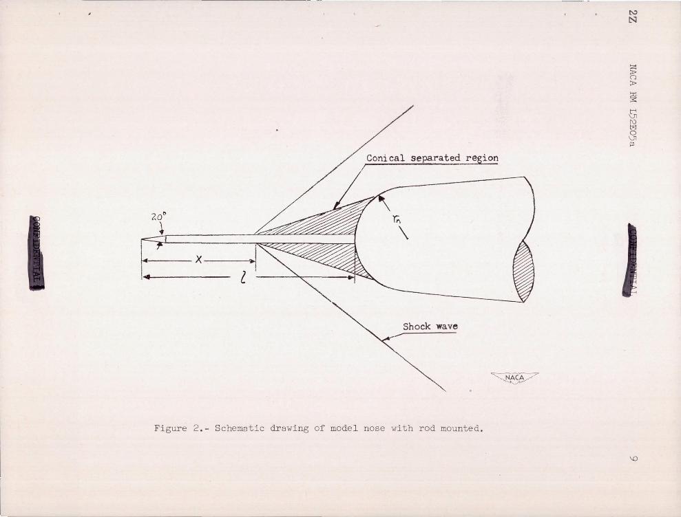
The flow in front of a blunt nose has been found to be easily separated from the surface of a slender rod or needle which projects forward of the nose. (See ref. 4. ) This separation is a result of the interaction of the bow wave and the boundary layer on the rod. The separated region is found to form approximately a conical shape, and the accompanying shock is very nearly the conica l shock expected for a solid cone geometrically similar to the separation region.
2 NACA RM L52E05a
If some forward-projecting device can be found which operates satisfactorily under va r ying conditions of Mach number and angle of attack, practical use of this phenomenon might be made to reduce the drag of blunt-nosed missiles . The purpose of this investigation was to study the separation phenomenon at an angle of attack of 00 so that the factors determining optimum rod length might be understood .
SYMBOLS
nose - drag coefficient based on maximum frontal area
pressure rise across shock wave
2 distance from tip of rod to nose of model
q local dynamic pressure
radius of model at b ase
radius of hemispherical nose
Reynolds number based on distance x
S station along model axis measured from tip, in.
length of basic model, in.
x distance from tip of rod to point of separation
y radius at any point on model, in .
MODELS AND TESTS
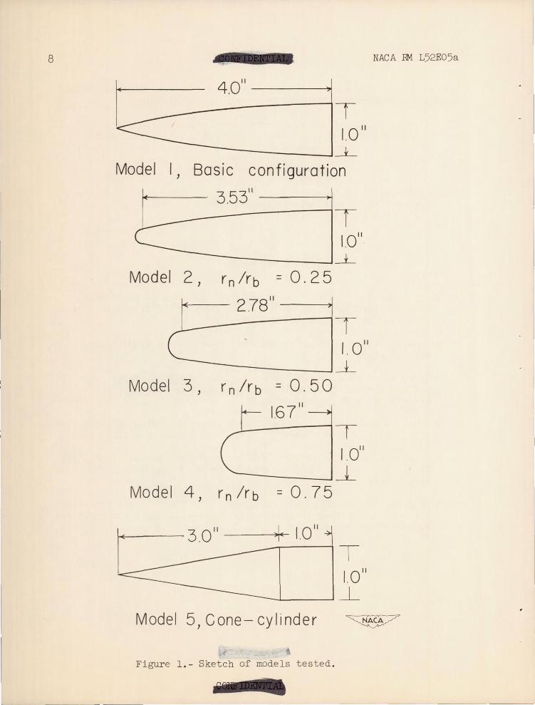
A sketch of the configurations tested is shown in figure 1 . The models were fitted to a small strain- gage drag ba l ance .
Modell, the basic configuration, r epresents a nOse design which has a minimum wave -drag coefficient for a given f i neness ratio accor ding to the slender -body theory . (See ref . 5. ) The fineness ratio used for model 1 waS 4. 0. The or dinates for this type of body follow the e quation
- - - --- ."."- -------
NACA RM L52E05a
where
t 2 ~ - 1 Sb
For model 1 the value of Sb was 4.0 inches and rt was 0.5 inch.
3
( 1)
Models 2, 3, and 4 were designed by replacing the nose point of model 1 with spherical segments having a radius one-quarter, one-half, and three-quarters, respectively, of the base radius . On each model the spherical segment and the unmodified portion of the model were tangent at the meeting pOint, behind which each model was identical to model 1.
Model 5, a cone cylinder of approximately the Same volume and length as modell, was used merely for comparison of drag with the other configurations.
On models 2 and 3 a small diameter rod of variable length was tested. The diameter of the rod used on model 2 was 0.020 inch and for model 3 the rod diameter was 0 . 040 inch, so that the ratio of rod diameter to nose radius would be constant. The tip of each rod was a 100 half-angle cone. Figure 2 is a schematic drawing of a model nose with a rod mounted.
All tests were run in a blowdown jet of the Langley gas dynamics laboratory at a Mach number of 2.72. The test section measures 3 by 5 inches. The Reynolds number of the undisturbed flow was 1.83 X 10⁶ per inch and all tests presented were run at an angle of attack of 00 ,
The strain-gage bala.nce was rea.d from a Brown potentiometer. Flow was not permitted to enter the sting mount at the rear of the model, and the pressure on the base of the model was measured on a mercury manometer. The coefficients were based on zero base drag.
4 NACA RM L52E05a
RESULTS AND DISCUSSION
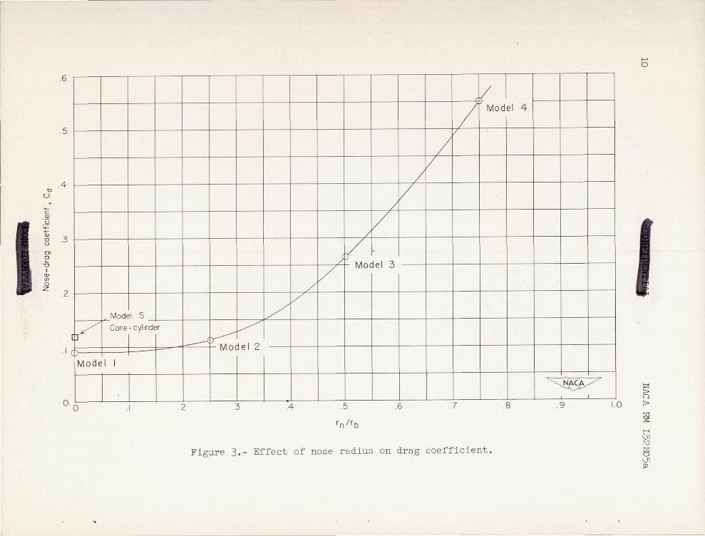
The drag coefficients of models 1 to 5 were measured on the drag balance . (See fig . 3 . ) As was previously mentioned, the drag increase
r n is not severe for a value of = 0 . 25 . It is interesting to note that
rb
the drag of model 2 (~ = 0 . 25 ) is about the same as that of model 5,
the cone cylinder .
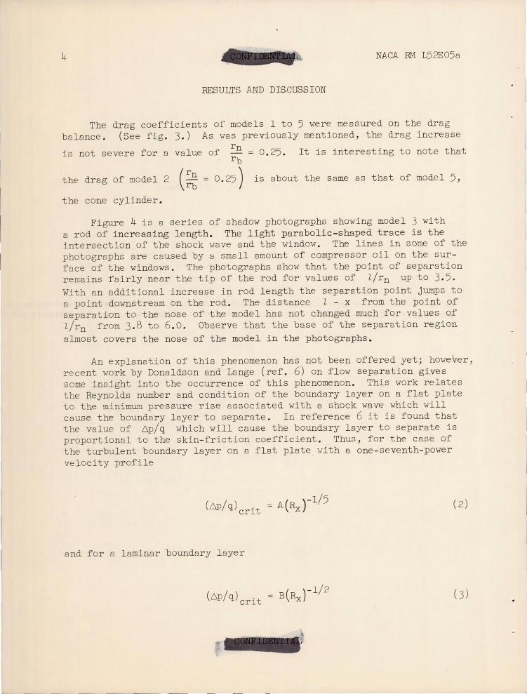
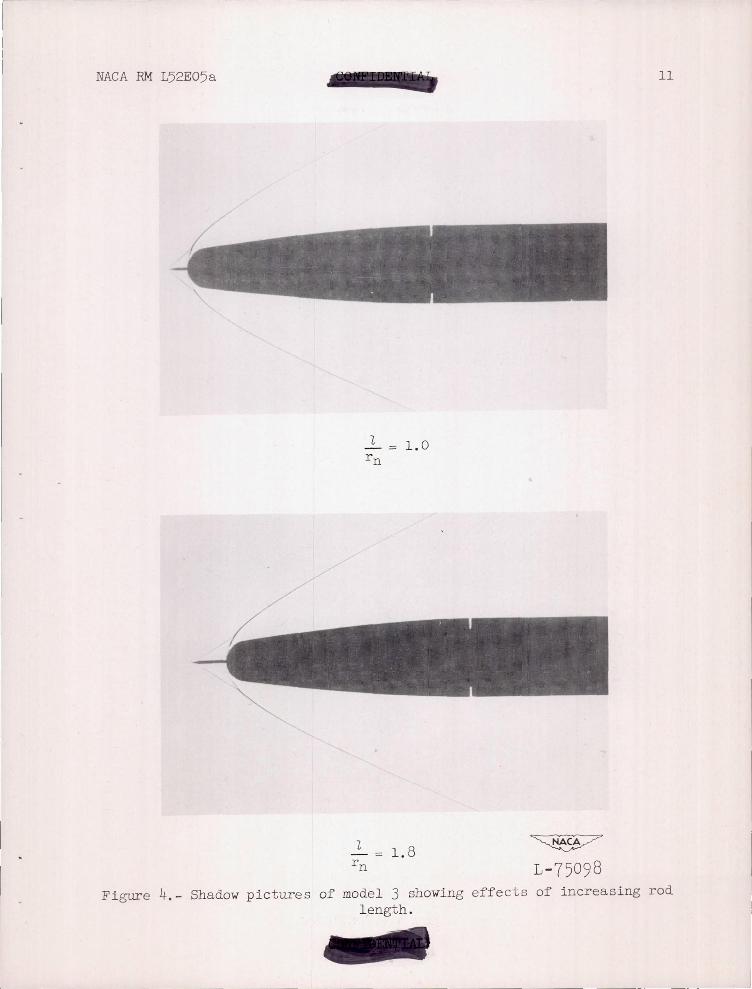
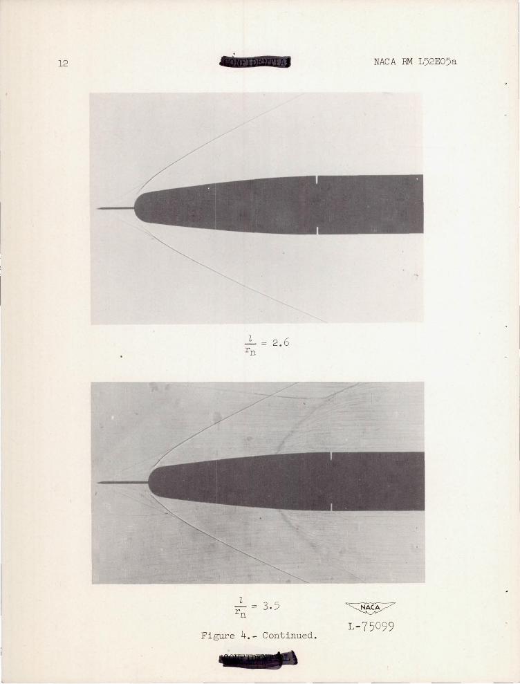
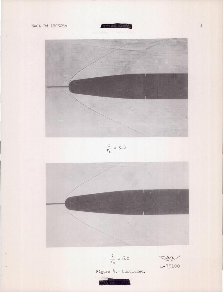
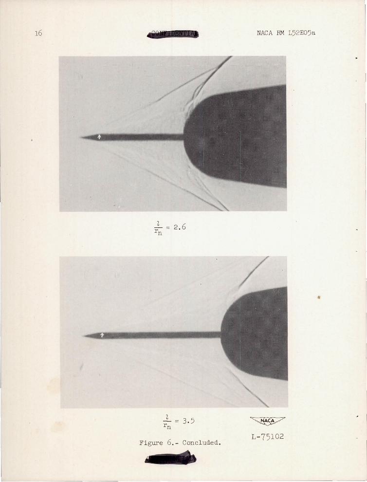
Figure 4 is a series of shadow photographs showing model 3 with a r od of i ncre as ing length. The light par abol i c-sha.pe d trace is the intersection of the shock wave and the window . The lines in some of the photographs are caused by a small amount of compressor oil On the surface of the windows . The photographs show that the point of separation remains fairly near the tip of the rod for values of llrn up to 3 . 5 . With an additional increase in rod length the separation point jumps to a point downstream on the rod . The distance 1 - x from the point of separation to the nose of the model has not cha.nged much for values of llrn from 3 . 8 to 6 . 0 . Observe that the base of the separation region almost cover s the nose of the model in the photogr aphs .
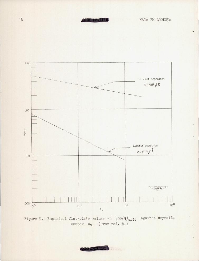
An explanation of this phenomenon has not been offered yetj however, recent work by Donaldson and Lange (ref . 6) on flow separation gives some insight into the occurrence of this phenomenon . This work relates the Reynolds number and condition of the boundary layer on a flat plate to the minimum pressure rise associated with a shock wave which will cause the boundary layer to separate . In reference 6 it is found that the value of 6p/q which will cause the boundary layer to separate is proportional to the skin- friction coefficient . Thus, for the case of the turbulent boundary layer on a flat plate with a one - seventh- power velocity profile
and for a laminar boundary layer
(6 I ) = B(Rx )-1/2 p q crit
( 2)
NACA RM L52E05a
where (6P/q)crit is the minimum pressure rise which will cause the
boundary layer to separate and A and B are constants with values of 4.44 and 24. 6, respectively. The curves of equations (2) and (3) are shown in figure 5. For a boundary layer on a slender shaft, aB
5
in the present instance, where the radius of the shaft is not large as compared to the boundary-layer thickness, the preceding work is not directly applicable . However, the results show certain trends which may be used in the present study. Emphasis is placed, first, on the small change in the value of (6P/q)crit with Reynolds number for a turbulent
boundary layer as compared with that of a laminar boundary layer and, second, on the appreciable difference in the value of (6p/q) "t for
crl the two curves at any given Reynolds number for the range shown.
If these results are applied to the separation of the boundary layer from the small rod, the conical shock wave which just precedes the point of separation must have exactly that pressure rise which will cause the boundary layer to separate at that particular Reynolds number and type of boundary layer . Consequently, for given conditions and configurations, the separation point may be thought of as determined in the following manner : The cone vertex of the separated region moves forward On the rod (cone angle and Reynolds number Rx decreasing) to that pOint where a further decrease in cone angle would make the pressure rise insufficient to separate the boundary layer.
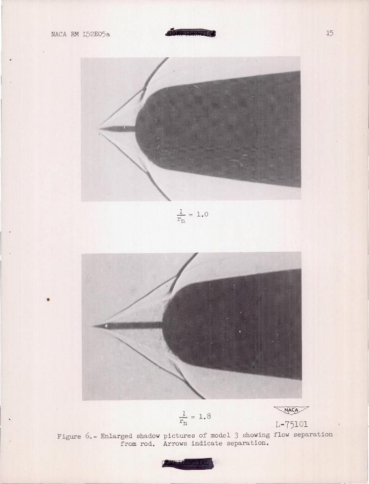
For short rod lengths the separation point is determined by the laminar variation of (~/q)crit with Rx. With increasing rod length
the laminar separation point will move back from the rod tip (fig. 6) until the value of Rx for transition is reached. For longer rod lengths, the separation must follow the turbulent variation of (6P/q)crit.
Since experimental results show that a turbulent boundary layer requires a larger pressure rise in order to separate, the cone angle of the separation must be greater; so, the point of separation "jumps" back on the rod.
In cases where the separation is laminar, the Reynolds number Rx is low. Because of the high Reynolds number per inch at which this experimental work was run, the distance x from the tip of the rod to the point of separation was extremely short. The shadow photographs (fig. 6) of the region were considerably enlarged and show that there is a definite increase in the value of x with increasing rod length. The small arrows indicate the approximate point of separation.
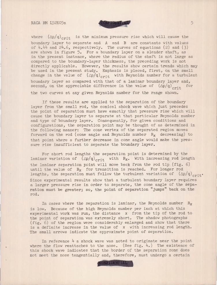
In reference 4 a shock wave was noted to originate near the point where the flow reattaches to the nose. (See fig . 4.) The existence of this shock wa.ve indicates that the border of the separation zone does not meet the nose tangentially and, therefore, must undergo a certain
6 NACA RM L52E05a
amount of turning. The flow field in the region of the base of this shock wave follows a pattern similar to that shown
/shock wave
One stream line should exist which intersects the nose at A. This indicates a stagnation point, provided at this point the effect of the local shearing stresses on the flow near the surface balances the effect of the pressure rise across the shock wave. The pressure recovered at A will not be large, but the pressures measured on the surface of the nose (ref. 4) clearly indicate that a maximum is obtained in this region.
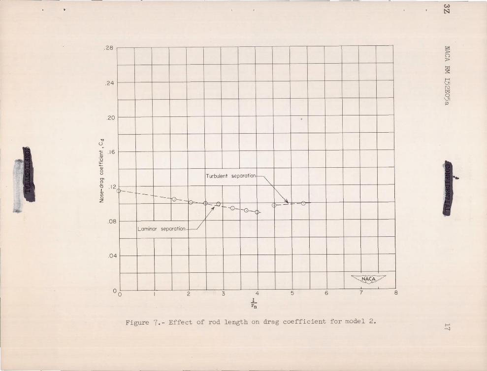
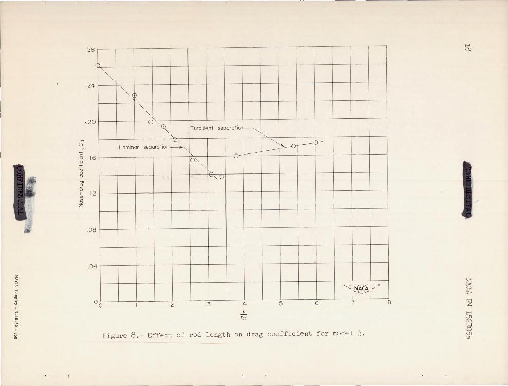
Figures 7 and 8 show the decrease in the sum of wave and friction drag obtained on models 2 and 3, respectively, when rods of varying length are mounted. A conclusion may be reached from these figures that the lowest drag is given by the longest rod length for which laminar separation occurred.
CONCLUDING REMARKS
An experimental investigation was made of flow separation from a pointed rod projecting ahead of a blunt nose. It was found that the wOl"k of Donaldson and Lange which relates the separation of a boundary layer to the pressure rise across the accompanying shock wave could be used to explain the present phenomenon.
Strain-gage drag tests at a Mach number of 2 .72 and at an angle of attack of 00 indicated that the drag of bodies of revolution having near-hemispherical noses could be appreciably reduced through the use of these projecting rods. The lowest drag coefficient obtained with the use of the rods occurred when the boundary layer separated while
--~- -- --~-
NACA RM L52E05a 7
still laminar. Thus) the longest rod extension which still maintained laminar separation resulted in the lowest drag coefficient.
Results of drag tests of several noses without projecting rods agreed qualitatively with previous work; that is) the drag increase was very high for large values of the ratio of nose radius to body radius) but for a value of 0 . 25) the drag increase was small.
Langley Aeronautical Laboratory National Advisory Committee for Aeronautics
Langley Field) Va.
REFERENCES
1. Hart) Roger G. : Flight Investigation of the Drag of Round-Nosed Bodies of Revolution at Mach Numbers From 0. 6 to 1.5 Using RocketPropelled Test Vehicles . NACA RM L5lE25) 1951 .
2. Walchner) 0 . : Systematic Wind- Tunnel Measurements on Missiles. NACA TM 1122) 1947 .
3. Eggers) A. J.) Jr.) Dennis) David H. ) and Resnikoff) Meyer M.: Bodies of Revolution for Minimum Drag at High Supersonic Airspeeds. NACA RM A51K27) 1952 .
4. Moeckel) Wolfgang E.: Flow Separation Ahead of a Blunt Axially Symmetric Body at Mach Numbers 1. 76 to 2 . 10. NACA RM E51I25 ) 1951.
~ ,-5. Von Karman) Th . : The Problem of Resistance in Compressible Fluids.
GALCIT Pub. No . 75 ) 1936 . (From R. Accad. d'Italia) Cl. Sci. Fis., Mat. e Nat . ) vol. XIV) 1936 . )
6 . Donaldson) Coleman duP . ) and Lange, Roy H.: Study of the Pressure Rise Across Shock Waves Required to Separate Laminar and Turbulent Boundary Layers. NACA RM L52C21, 1952 .
8
4.0" ___ ~
-------,T 1.0 II
-------.J~
Model I, Basic configuration
1===. 353" T
T 1.0"
------.J~ Mo del 3, r n I r b = o. 5 0
1.67" ~----'T
1.0" ------..J~
Model 4, r n Irb = 0.75
-~~E 1.0" 1 T 1.0"
~----'~
NACA RM L52E05a
Model 5, Cone- cylinder ~
Figure 1 .- Sketch of models tested .
Conical separated region
x ~ , ~ ~ z < ~
Shock wave
~
Figure 2 .- Schematic drawing of model nose with rod mounted .
-, ~ 1
~ o ~
~ ~ ~ o VI III
\0
I
r
.6
.5
.4 -0
U
+-c Q)
·u ;;: ... Q)
.3 0 u (Jl
~ "0
I Q) If)
0 z .2
. 1
00 .1 .2 .3 .4 .5 .6 .7
r n Irb
Figure 3.- Effect of nose radius on drag coefficient .
.8 .9 1.0
b
s; o ~
~ t-' \Jl f\)
~ \Jl Pl
NACA RM L52E05a 11
1. 0
1. 8 1-75098
Figure 4.- Shadow pictures of model 3 showing effects of increasing rod length .
12
I - == 2. 6
Figure 4. - Continued .
- ... ' -- _ .. -
NACA RM L52E05a
~ L- 75099
NACA RM L52E05a 13
3. 8
2 - = 6.0 rn ~
L- 75100 Figure 4.- Concluded .
L
14 NACA RM L52E05a
1.0 I-----------------------.----------------------~--------------------~
.10
0-"-0. <l
.01
Turbulent separat ion I
4.44(Rxf5"
Laminar separat ion 1.
24.6(Rxf 2
Figure 5. - Empirical flat -p l ate values of , 6P/Q) crit against Reynolds
number Rx. (From ref . 6. )
.... . _. ~
I .
•
NACA RM L52E05a
l == 1 0 .
1.8 ~ L-75101
15
Figure 6. - Enlarged shadow pictures of model 3 showing flow separation from rod. Arrows indicate separation.
NACA RM L52E05a
2 - == 2. 6 rn
~ . I
Figure 6.- Concluded . L- 75102
v
" u
.28
.24
.20
C .16 (l)
·0 :;= (l)
o U
0' o .a .12
I (l) en o Z
.08
.04
(1)--
00
---r-_ ro--h.
Laminar separation l-/
2
Turbulent separat ion
~
'- ,--u !/- 1--0_
3
~ iJ-
4
1.. rn
~ (l)- v
~ - , ,
5 6 7
Figure 7.- Effect of rod length on drag coefficient for model 2 .
8
w N
s; () ;t>
~ ~ f\) tzj o \J1 III
f--' -'I
z > ()
> ~ " .. ~
-;> ';" '" .. "" g:
6
.28
.24
•. 20
"0
U
C . 16 <I>
'u ;;::: 'Ci; 0 U
01 e '0
I <I>
12 til 0 z
.08
.04
00
"" " " "lD
'" " \.: "0
" Laminar separation ~"
2
Turbulent separation--..........
i'" 0"
" 1,>-~" u
3
,..., . '-'
4 l
rn
--I'---~
--~ . -0 . -' D-
~ I I
5 6 7
Figure 8.- Effect of rod length on drag coefficient for model 3.
I
l J I
8
~
~ (j
;I>
~ t-' \)l f\) tr.l o \)l III


UNCLASSIFIED
UNCLASSIFIED .' ,"''''''''' ---~ ........
.. I~ -:~ ...
, '
UNCLASSIFIED