Embed Size (px)
Citation preview

AlCo 81
-C- -
mn
Ui Techuou.ma
NACA
RESEARCH MEMORANDUM
LOW-SPEED CASCADE INVESTIGATION OF LOADED
LEADING-EDGE COMPRESSOR BLADES
By James C. Emery
Langley Aeronautical Laboratory Langley Field, Va.
CLASSIFIED DOCUMENT
This material contains information affecting the National Defense of the United States within the meaning of the espionage laws, Title 18, U.S.C., Secs. 793 and 794, the transmission or revelation of which in any manner to an unauthorized person is prohibited by law.
NATIONAL ADVISORY COMMITTEE FOR AERONAUTICS
WASHINGTON January 11, 1956
C Ni4-iEEt,UIAJ )i• - / 0
7- :Z.)-41.
https://ntrs.nasa.gov/search.jsp?R=19930093818 2020-04-16T14:27:39+00:00Z
ERRATA
NACA RM L55J05
LOW-SPEED CASCADE INVESTIGATION OF LOADED LEADING-EDGE COMPRESSOR BLADES
By James C. Emery
January 11, 1956
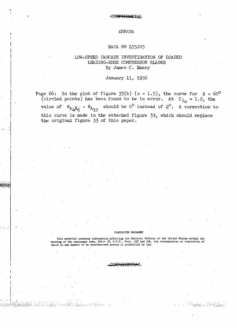
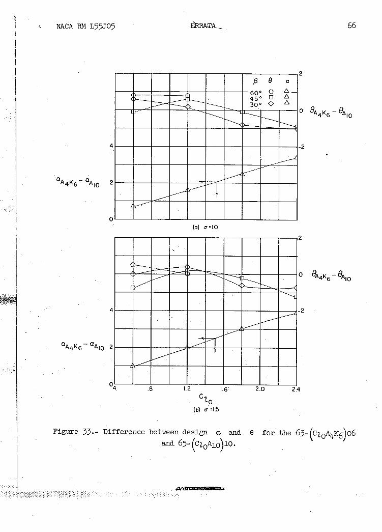
Page 66: In the plot of figure 33(b) (ci = 1.5) ., the curve for f3 = 600 (circled points) has been found to be in error. At C 0 = 1.2, the
value of e - should be 00 instead of 20. A correction to A lO this curve is made in the attached figure 33, which should replace the original figure 33 of this paper.
CLASSIFIED DOCUMENT
This material contains information affecting the National Defense of the United States within the meaning of the espionage lava, Title 18, U.S.C.., Sees. 793 and 794, the transmission or revelation of which in any manner to an unauthorized person is prohibited by law.
8 a
60° Q L_ 450 0 L
300 L J—
4
A 4 K 6 A10 2
0
2
0OAIO
-2
NA.CA RN L55J05
BRATA....
(a) 0- = 1.0
2
0
4 -2
2
04. .8 1.2 .6 2.0 2.4
C 1 '-0
(b) a- =1.5 . .
Figure 53.- Difference between design Ct and U for the 63 (CZOA4K6) o6 and 67- (cl.0A10)10.
ERRATA NO. 2
NACA RM L55J05
LOW-SPEED CASCADE INVESTIGATION OF LOADED LEADING-EDGE COMPRESSOR BLADES
By James C. Emery
June 1, 1956
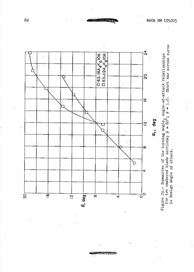
Page 62: Attached corrected figure 29 should replace the original figure 29 of this paper.
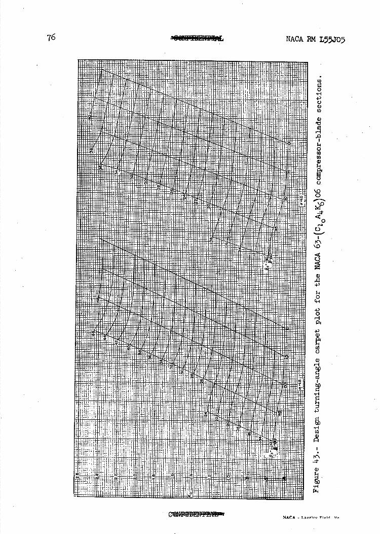
Page 76: The scale label for the ordinate in figure 43 should be C
instead of Co.
CLASSIFIED D(XUMENT
This material contains information affecting the National Defense of the United States within the meaning of the espionage laws, Title 18, U.S.C., Sees. 793 and 791, the transmission or revelation of which in any manner to an unauthorized person is prohibited by lay.
NACA RM L55J05 CWIDEI1T.,
NATIONAL ADVISORY COMMITTEE FOR AERONAUTICS
RESEARCH MEMORANDUM
LOW-SPEED CASCADE INVESTIGATION OF LOADED
LEADING-EDGE COMPRESSOR BLADES
By James C. Emery
SUMMARY
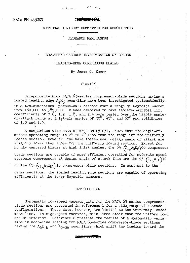
Six-percent-thick NAPA 63-series compressor-blade sections having a loaded leading-edge AK6 mean line have been investigated systematically
in a two-dimensional porous-wall cascade over a range of Reynolds number from 160,000 to .385,000. Blades cambered to have isolated-airfoil lift coefficients of 0.6, 1.2, 1.8, and 2.11 were tested over the usable angle-of-attack range at inlet-air angles of 30°, 45 0 , and 600 ana solidities of 1.0 and 1.5. . . . .
A comparison with data of NACA RN L51G31, shows that the angle-of-attack operating range is 2 0 to 40 less than the range for the uniformly loaded section; however,, the wake losses near design angle of attack are slightly lower than those for the uniformly loaded section. Except for highly cambered blades at high inlet angles, the 63_(C 1 A4K6)06 compressor-
blade sections are capable of more efficient operatiorifor moderate-speed subsonic compressors at design angle of attack than are the 65_(C1A10)10
or the 65- (c 1 A218b)1O compressor-blade sections. In contrast to the
other sections, the loaded leading-edge sections are capable of operating efficiently at the lower Reynolds numbers.
INTRODUCTION
Systematic low-speed cascade data for the NACA 65-series compressor-blade sections are presented in reference 1 for a wide range of cascade configurations. These data, however, are limited to the uniformly loaded mean line. In high-speed machines, mean lines other than the uniform load are of interest. Reference 2 .presents the results of a systematic varia-tion in mean-line loading for NACA 65-series compressor-blade isections having the A6I4b and A2I8b mean lines which shift the loading toward the
2 NACA RM L55J05
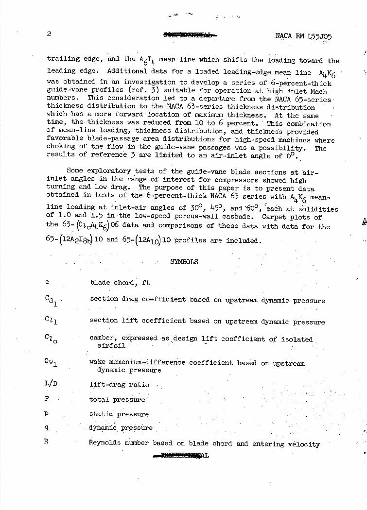
trailing edge, and the A 6I mean line which shifts the loading toward the
leading edge. Additional data for a loaded leading-edge mean line AK6
was obtained in an investigation to develop a series of 6-percent-thick guide-vane profiles (ref. 3) suitable for operation at high inlet Mach numbers. This consideration led to a departure from the NACA 65-series thickness distribution to the NACA 63-series thickness distribution which has a more forward-location of maximum thickness. At the same time, the thickness was reduced from 10 to 6 percent.: This combination of mean-line loading, thickness distribution, and thickness provided favorable blade-passage area distributions for high-speed machines where choking of the flow in the guide-vane passages was a possibility. The results of reference 3 are limited to an air-inlet angle of 00.
Some exploratory tests of the guide-vane blade sections at air-inlet angles in the range of interest for compressors showed high turning and low drag. The purpose of this paper is to present data obtained., in tests of; the 6-percent-thick NACA 63 series with AK6 mean-
line loading at inlet-air angles of 30 0 , 150, and '&)°, eaáh at s'olidities of 1.0 and 1.5 in the low-speed porous-wall cascade. Carpet plots of the 63-(CiAK6)06 data and, comparisons of these data with data for the
65-(12A218b)10 and 65- (12A10)10 profiles are included.
S0LS
c blade chord, ft
Cd1 section drag coefficient based on upstream dynamic pressure
section lift coefficient based on upstream dynamic pressure
Cj camber, expressed as design lift coefficient of isolated airfoil
Cwl wake momentum-difference coefficient based on upstream dynamic pressure
L/D lift-drag ratio
P total pressure -
p static pressure
dynamic pressure
R Reynolds number based on blade chord and entering velocity
NACABIvIL75JO5S 3
P-p S pressure coefficient,
C11
M angle between the inlet flow and the blade chord, deg
13 inlet-air angle, angle between the inlet-flow direátion and perpendicular to the cascade, deg
0 flow turning angle, deg
a solidity, chord of blades divided by: tangential spacing
PR resultant pressure coefficient; difference between local upper-and lower-surface pressure coefficients
AT - ratio of blade-passage throat area to area of upstream flow A1
X blade chord, percent
y blade thickness, percent of chord
Subscripts:*:
d design, when used with blades
1 local
1 upstream
2 downstream of blades
APPARATUS, ST PROGRAM ) AND PROCEDURE S
Description of Test Equipment
The test apparatus used in this investigation was the Langley 10-inch low-speed porous-wall cascade (fig. 1) described in reference ! which was modified by reducing the test-section width from 20 inches to 10 inches. Five-inch chord blades were used to give an aspect ratio of 2.0. Seven blades were used in the cascade except at theinlet-àirangle of 300 and solidity of 1.0 for which only five blades could be fitted into the tunnel. The side walls in the entrance to the test section contained a flush-type boundary-layer suction slot one chord length upstream-from-the blade sec-tions being tested. In all tests a screen of1/2-inch mesh hardware cloth
Ii. NACA BM L55J05
was inserted at the entrance to the test section. This screen was inserted in order to increase the turbulence level of the entering air in an attempt to reduce the laminar separation on the test airfoils. The addition of the above screen made the turbulence level comparable to that of the Langley 5-inch cascade (ref S. , 1 2, Ii., and 5). Data from the two cascades may be compared directly without consideration of the effects of turbulence.
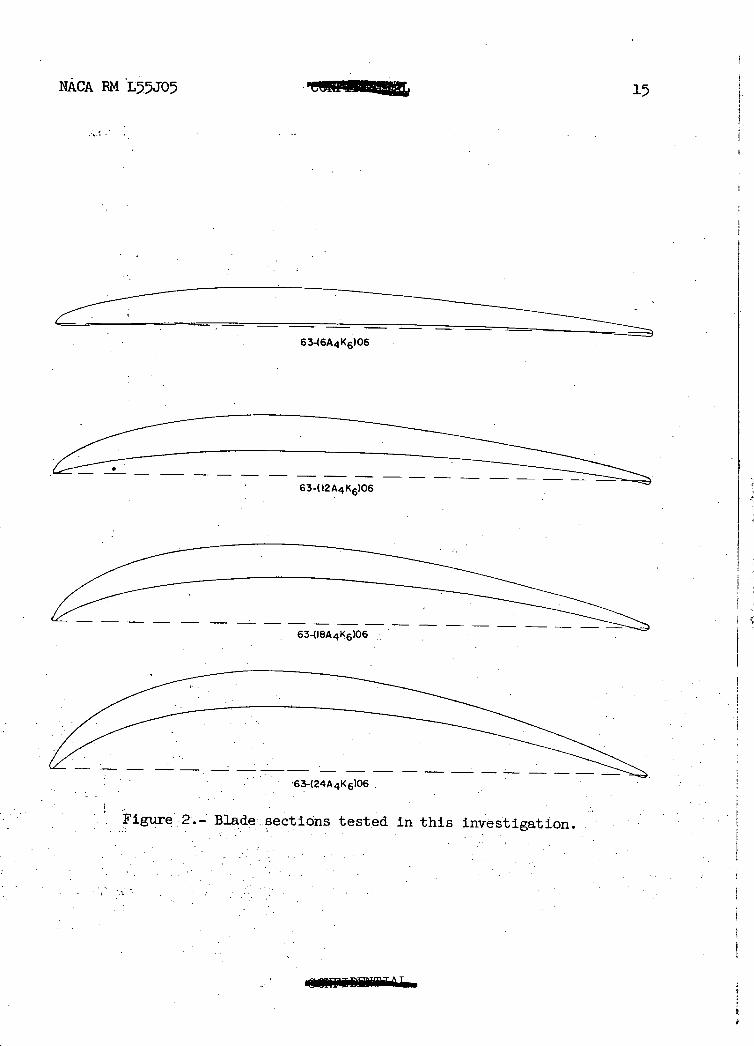
Description of Airfoils
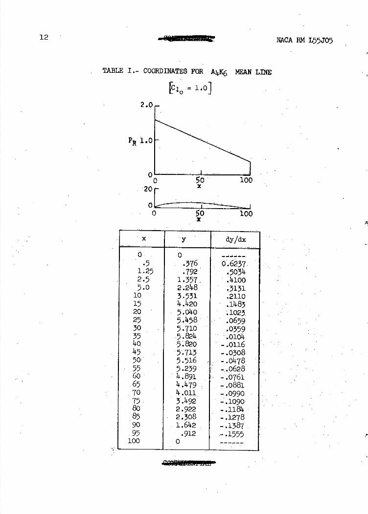
The mean line and thickness distribution used in this compressor-blade family are the same as those of reference 3 and profiles of the sections tested are illustrated in figure 2. The mean line is a combi-nation of the a = 0 and the- a = 1.0 mean lines. In order to remove the reflex curvature near the trailing edge which is characteristic of the a = 0 mean line, the uniform loading of the a = 1.0 mean line was added in the proportion of ) . to 6. The resulting mean line Is designated as the AK6 mean line. The coordinates for this mean line for CI O = 1.0
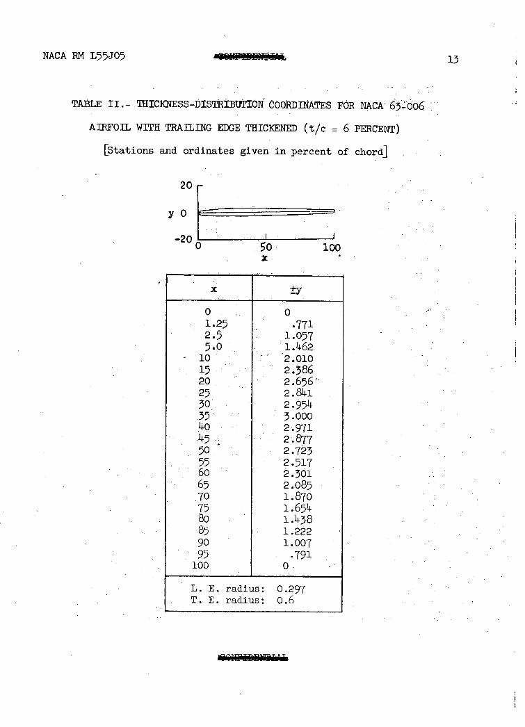
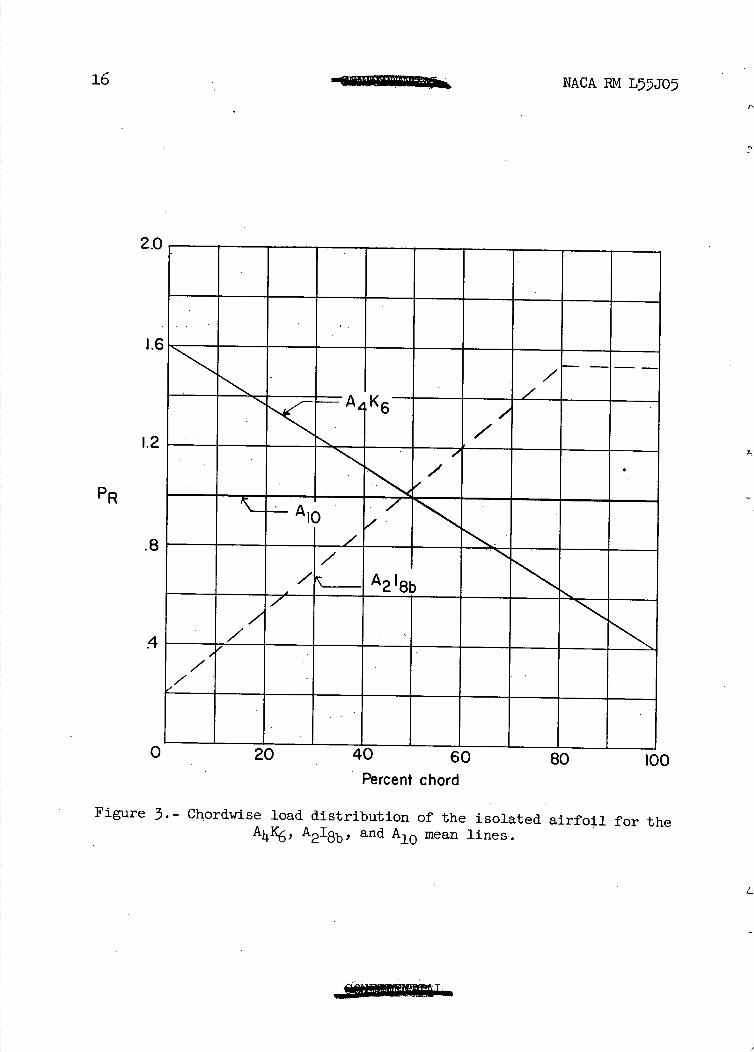
are given in table I. The coordinates for the thickness distribution used (NACA 63-006 airfoil) are given in table II and the chordwise loading distribution is shown in figure 3.
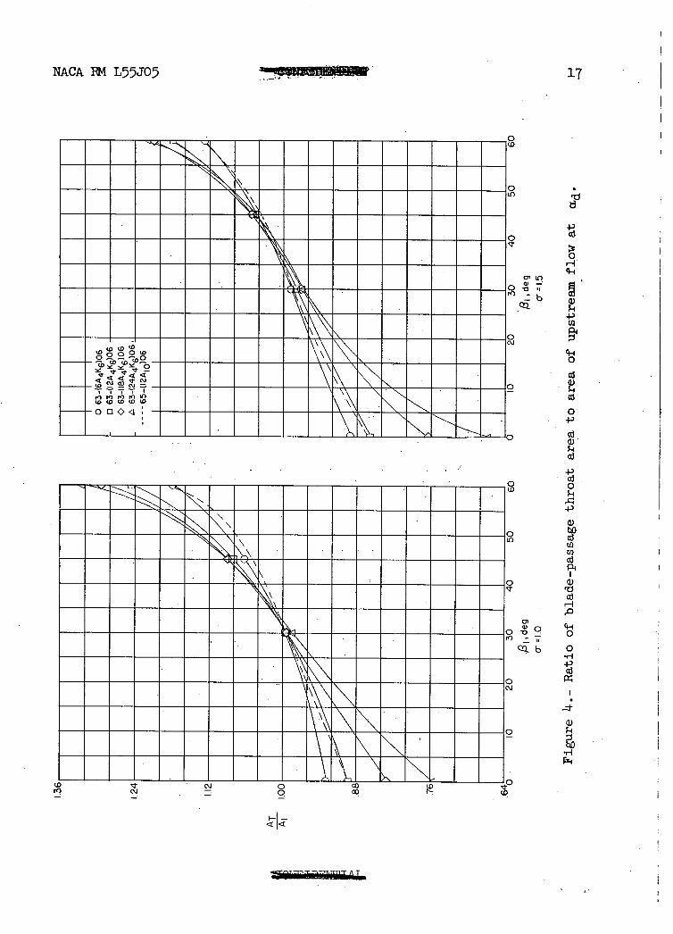
Choking in blade rows is determined by the minimum passage or throat area. By laying out large-scale drawings of blade passages for the A4K6 blades at design angle of attack for various combinations
of inlet-air angle, solidity, and camber, the ratio of minimum passage area AT to inlet area A1 could be measured. Figure 4 presents AT/Al plotted against inlet-air angle for soliditles of 1.0 and 1.5
and camber of 0.6, 1.2, 1.8, and 2.4 for the A4K6 blade section. In
addition, AT/Ai for the A10 blade section C1 0 = 1.2 is given for comparison. It is apparent that shifting the loading to the leading edge has very little effect on the area ratio below an inlet angle of 400 . Above 100 the AK6 sections increase in passage area faster than the A10 - sections; hence,. the A4K6 sections are equal to A 10 sections in area ratio up to 400 and are more open at higher inlet-air angles.
Test Program and Procedure.
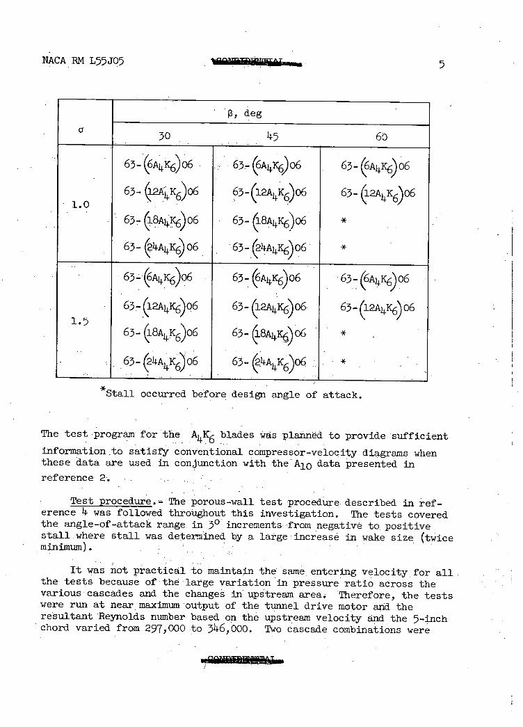
Test. program.- The combinatibns of inlet-air angle, solidity, and blade- section for which data are presented are shown in tabular form on the following page.
NACA RM L55J05 5
, deg G
30 45 60
63- (&) o6 63 (6A) 06 63- (6A) 06
63- 12K6 06 63-12AK606 63- 1K6)06
63- 8A06 6'3- (18^4K6)o *
63- 244K6 06 63- 2i Ai .Ico6 *
63_@A4K6)06 63- (6A4K6)06 63-(6A6)o6
63- 12A11•K6o6 63-(12A4 c6o6. 63-2A)1K6o6 1.5
63- (1&4K6)06 63- (18A4K6) 06 *
63-(2A K6)'06 63- ( *
*Stall occurred before design angle of attack.
The test program for the A1 K6 blades was planned to provide sufficient
information to satisfy conventional compressor-velocity diagrams when these data are used in conjunction with theA10 data presented in
reference 2.
Test procedure.- The porous-wall test procedure, described in ref-erence 4 was followed throughout this investigation. The tests covered the angle-of-attack range in 3° increments from. negative to, positive stall where stall was determined by a large increase in wake size (twice minimum).
It was not practical to maintain the same entering velocity for all the tests becauseof the large variation in pressure ratio across the various cascades and the changes in upstream area. 'Therefore, the tests were run at near maximum output of the tunnel drive motor and the resultant Reynolds number based on the upstream velocity and the 5-inch chord varied from 297,000 to 311.6,000. Two cascade combinations were
6 €J(ilLiE]- NACA RM L55305
tested at design angle of attack over a range of Reynolds number from 160,000 to 385,000 to assist in estimating performance at Reynolds numbers other than the usual test value.
Test measurements. - Blade pressure distributions, turning-angle surveys, and wake total-pressure loss were obtained using the methods of reference 1. Upstream conditions were measuredin the same manner as in reference 3.
Calculations.- The calculative procedure is completely described in reference 1. Brief definitions of wake, lift, and drag coefficient are repeated here. The wake coefficient C 1 represents the momentum
difference between the wake and the stream outside of the wake.All forces due to pressure and momentum changes across the blade row were summed to obtain the resultant blade-force coefficient. The resultant force coefficient was resolved into components perpendicular and parallel to the vector mean velocity to obtain the lift coefficient C 1 and the
0 drag coefficient Cd1 , respectively. All coefficients are based on the
upstream dynamic pressure q.
Accuracy of results. - The measured turning-angle accuracy was within ±0.50 near the design condition. For tests near positive or negative stall the accuracy was somewhat reduced because of increased wake widths in the plane of angle measurement..
The blade normal-force coefficient calculated from pressure rise and momentum considerations was compared with the normal-force coeffi-cient obtained by integration of the pressure distribution. Since these values would be affected by errors in turning angle, surface pressure, wake-survey readings, or a failure to achieve two dimensionality of the flow, this comparison is a check of the overall acceptability of the tests. The agreement between normal-force coefficients obtained by the aforementioned methods was within 5 percent. The lift coefficients presented were obtained: from momentum-considerations. -
The coordinates for the A4K6 mean line are presented in table I and the thickness-distribution coordinates for the NACA 63-006 airfoil with trailing edge thickened (t/c = 6 percent) are presentedin table II. The results for the various blade sections tested are presented in the following table for figures 4 to 43.
NACA RN L55J05 7
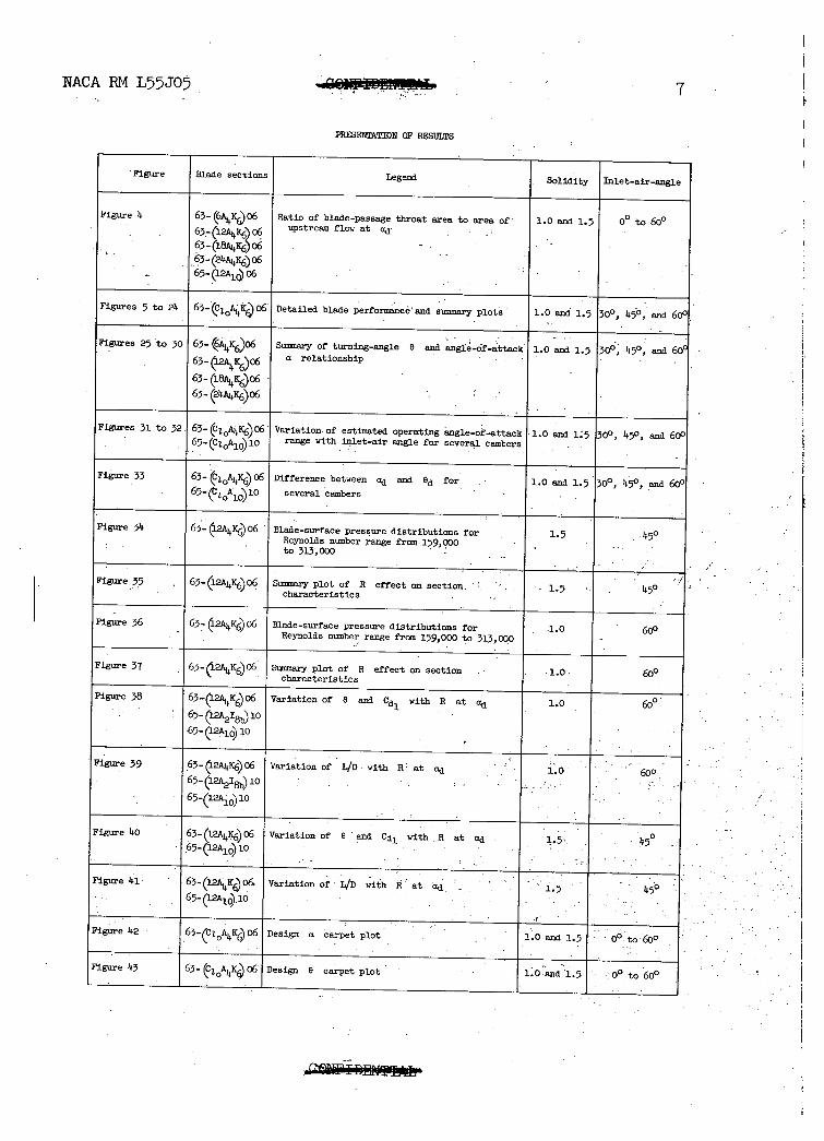
PRESERTAPION OF RgSULTS
- Figure Blade sections Legend Solidity
Figure 1 63- (6K)o6 Ratio of blade-passage throat area to area of- 1.0 and 1.5
qInlet-air-angle
• - 63- upstream flow at ad- - 63-(18A446)06 63- (2AK6) 06
-
65- (12A1 ) 06
Figures 5 to 21 63_(C2 0AKo6 Detailed blade performance and summary plots 1.0 an 1.5 300, 450 and 600
Figures 25 to 30 63- (6A 4y6)06 Summary of turning-angle e and angle-of-attack 1.0 and 1.5 300, 150, and 60P 63-2AK6)06 a relationship - -
63-(l8)06 -
- -
63- (21c6)o6- -- -
Figures 31 to 32 63- (ca 0 ic6)o6 Variation, of estimated operating angle-of-attack 1.0 and 15 300 , 450 , and 60° 65.. (CAio) 10 range with inlet-air angle for several cambers -
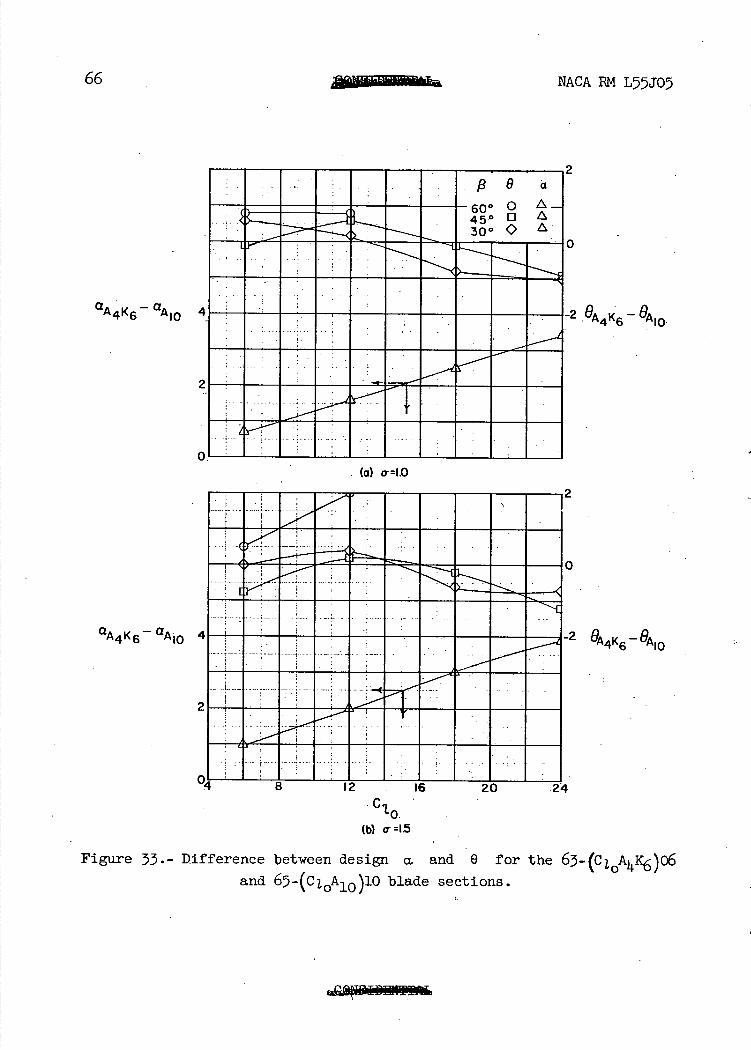
Figure 33 63-(C20AK6)06 Difference between ad and 8d for 1.0 and 1.5 30°, 145, and 600 65-(A10)10 several cambers -
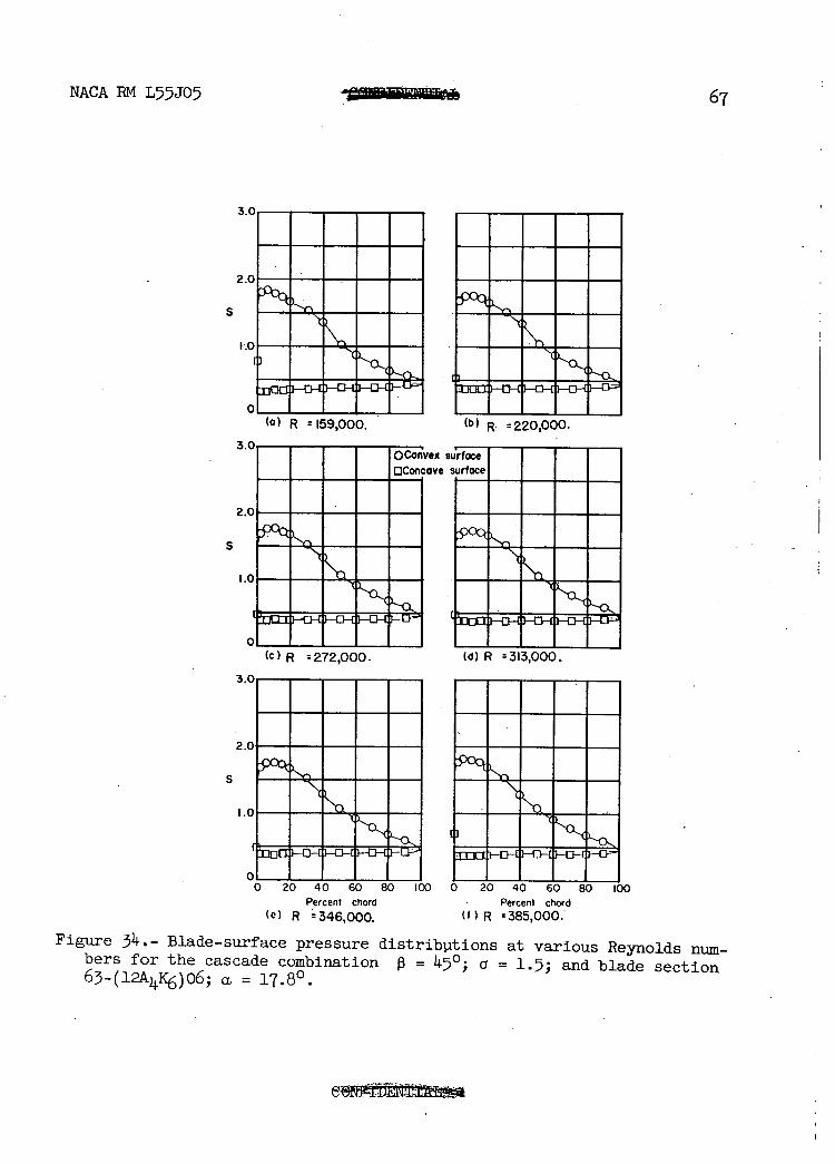
Figure 34 63- (l2106) O6 - Blade-surface pressure distributions for i.s Reynolds number range From 159,000 - to 313 1 000 - -- -
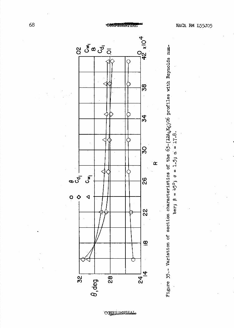
Fie 35 - 63-l2o6 Sumnary plot of R effect on section. '. - 1.5 k5° characteristics -
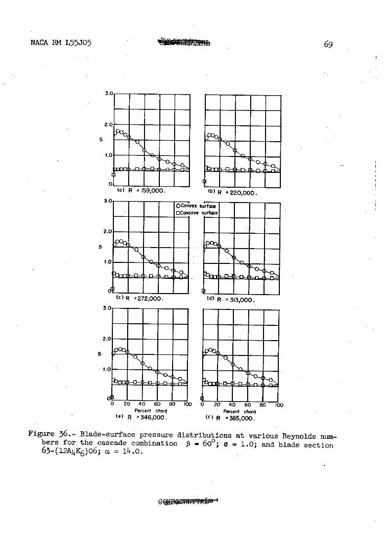
Figure 36 63- (l2Aklc6) 06 Blade-surface pressure distributions for -1.0 60° Reynolds number range from 159,000 to 313,000 -
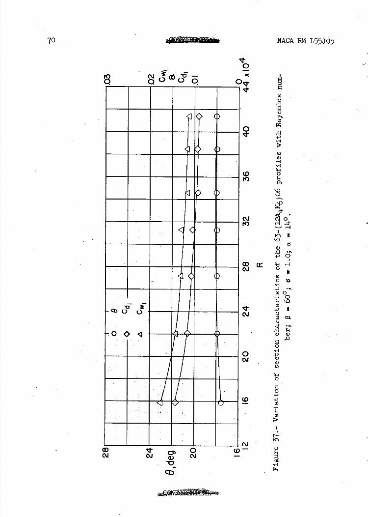
Figure 37 63_G2AkIC6)06 Summary plot of R effect on section 1.0 600 Characteristics
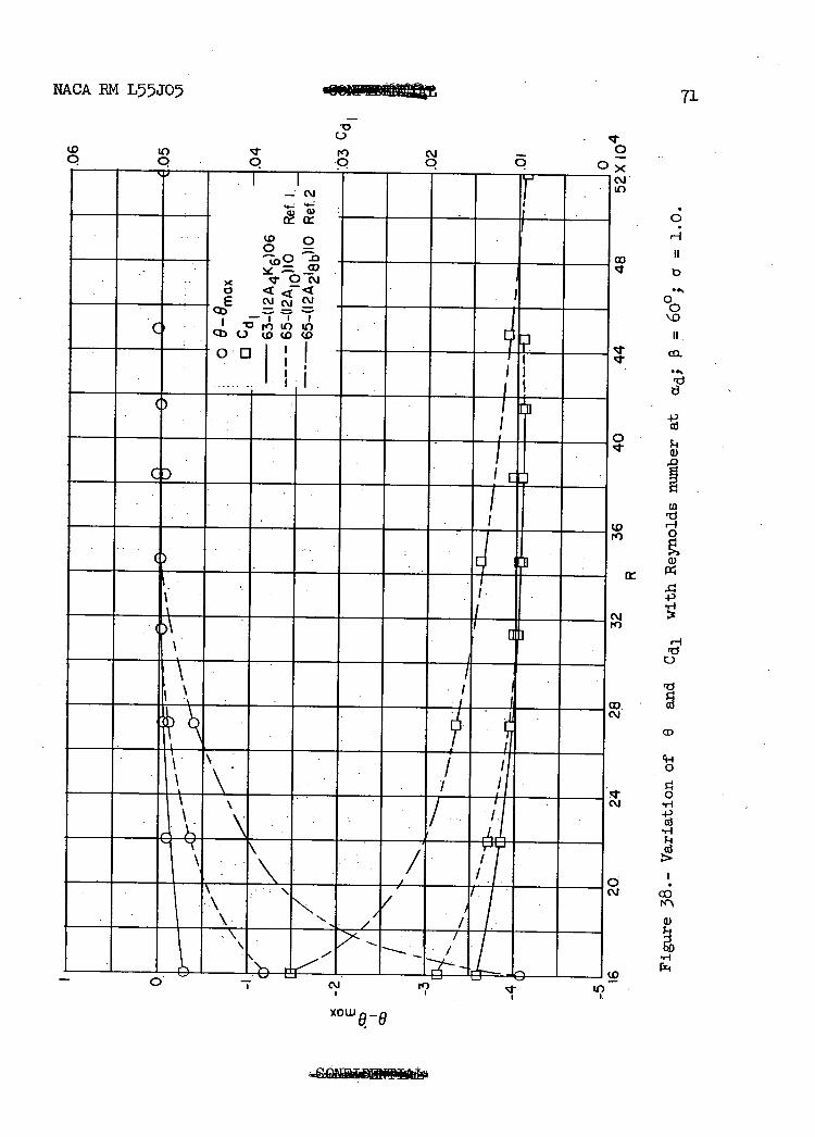
Figure 38 63_(12A41c6)06 Variation of 0 and Cd1 with R at ad 1.0 600 - 65-12_A2I)1O
65-(i2io)lo
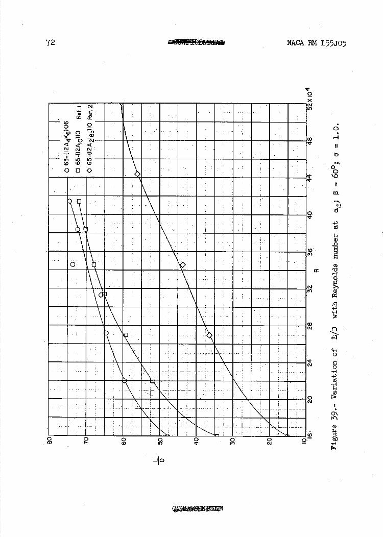
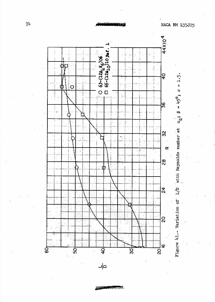
Figure 39 63- G2AIIJc6) 06 Variation of L/D with R at ad 1 C) 600 65_(1 2I)l0 • • - - '• -
65_(12A1 10 - -
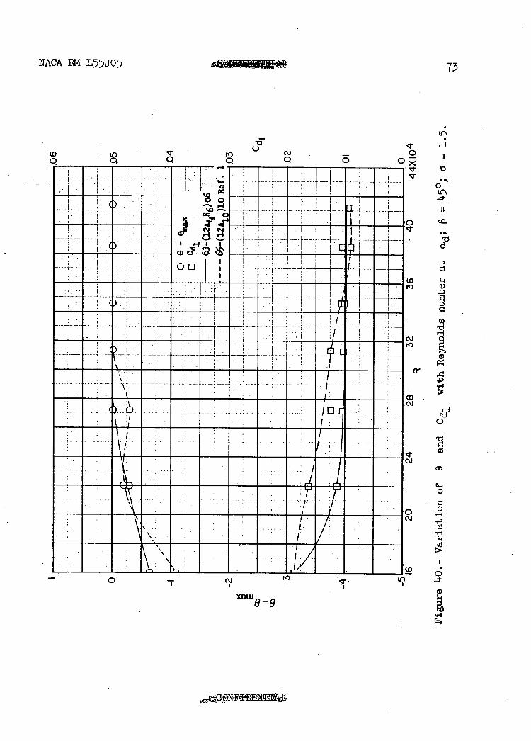
Figure kO 63- (i2A41c6) 06 Variation of 0 and Cd1 with • R at a 450 65-(12A10) 10 -
Figure ha 63 06. Variation of WD with B at ad 1 5 40 65-(12A10) 10
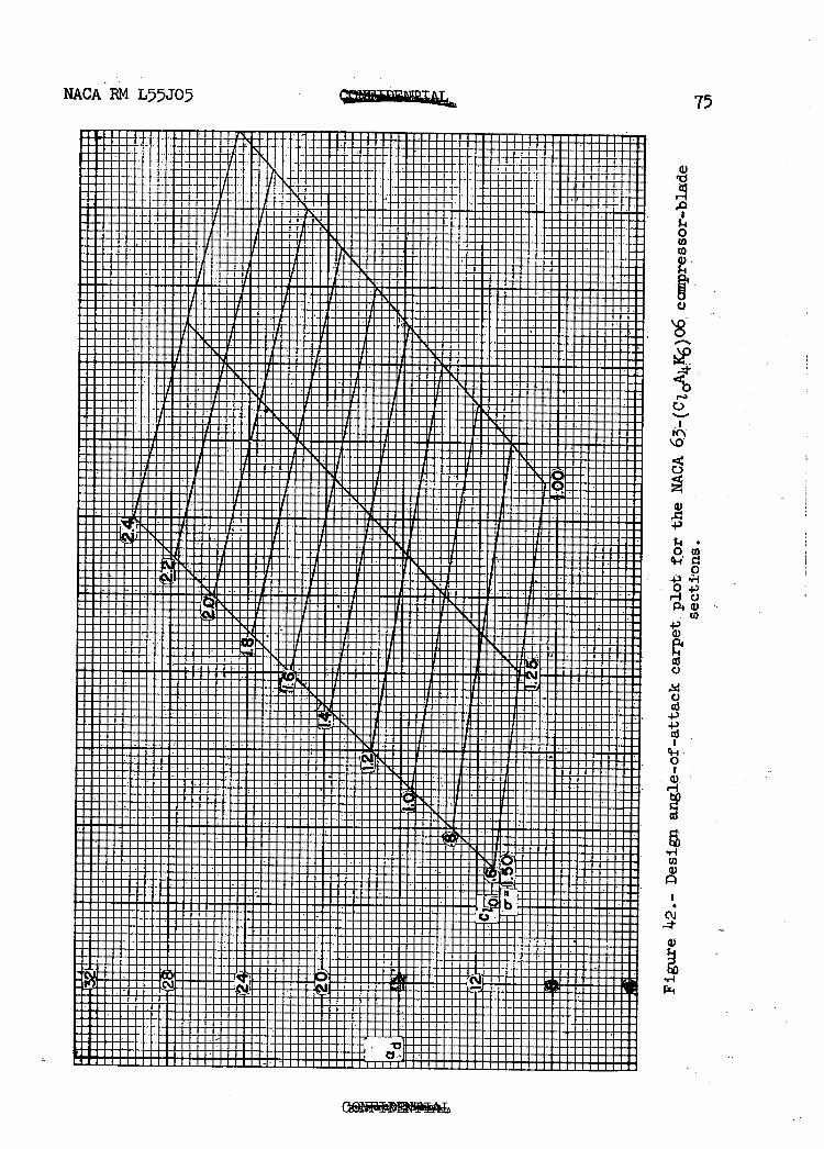
Figure 42 63_(CtOA4K6)06 Design a carpet plot 1.0 and 1.5 0° to-GO°
Figure 43 63_(ClOAkic)o6 Design 0 carpet plot
•
^Oa-nd1.5 • -'0° to 60°
8 NACA RM L55J05
DISCUSSION OF RESULTS
Operating Range
Summaries of the turning angle, angle-of-attack relationships for the four cambered blade sections tested are given for each inlet angle and solidity in figures 25 to 30. For combinations giving moderate pressure rises there are straight-line relationships for considerable portions of the curves. At the highest pressure-rise combinations ( = 60) the two-dimensional pressure rise is very near the stalling pressure rise and the straight-line relationship exists for only a small portion of the curve.
In order to select the upper and lower limitsof angle of attack, Howell's index of twice minimum drag (ref. 6) was used to estimate the useful operating range of the various sections at the solidity and inlet-angle conditions tested. In figures 25 and 26 a comparison of the operating range of the 63-(Ci 0A). K6)O6 blade sections with that of the65-(C, A "\l0 blade sections of reference 1 indicates a 20 to 60 \olO) / greater range for the 65- cc 1 A 0)10 sections for the conditions tested.
The smaller operating range of the 63- (cj 0Ajjc6)o6 sections is attributed to the difference in profile thickness (ref. 5). In addition to the effect of profile thickness ., the loaded leading edge of the 63_(C10A4K6)O6 sections has a steeper pressure gradient near the leading edge which tends to form a thick boundary layer on the convex surface; consequently, a reduction in operating range is to be expected.
Turning Angie
In figure 33 a comparison of the 63-(C1 AK 6)O6 and 65_(C10A0)10
blade sections is presented to show the differences indesign angle of attack and turning angle for these two different sections. In general, the difference is of the order of 10 for the design turning angle. The difference for the design angle of attack is 3.90 for the 65-(24A4Jc6)06 blade sections and decreases linearly with camber. It can be seen that at the three inlet-air angles (at design angle of attack) the difference between the turning angles for the two types of loading is small.,
Reynolds Number Effects
As shown in figures 35 and 37 the drag coefficient and turning angle remain almost constant above a Reynolds number of 220,000.
NACA RM L55J05 MOONPEMPI., 9
Figures 34 and 36 indicate nosignificant change in the pressure dis-tribution over the range of Reynolds number tested.
Figures 38 and 40 show the variation of 0 and Cd at ad with
Reynolds number for the 63_(12A 11.K6)06, 65-(12A2I8b) 10 , and the
65-(12A10)10 blade sections at 0 of 600 and 150, a of 1.0 and 1.5. The A2I8b. section is not included in the lower inlet-angle figure
because no data were available for that condition. The A4K6 section
has a lower critical Reynolds number than the A2I8b or the A10 sections
as indicated by the lower drag and higher turning angle at the lower end of the Reynolds number range. This is to be expected because of the adverse pressure gradient beginning at the leading edge of the A4K6 section. . .
The variation of the lift-drag ratio with Reynolds number for the 63- 2A '\06, 65- 2A 0))10
(l 4 w" 6) (l 1and the 65_l2A2I8blO blade section is
presented in figures 39 and 11.1 for inlet angles of 60 and 45 and-solidities of 1.0 and 1.5. The lift-drag ratios for the AK6 ' section
are generally higher than the values for the Aio section. Some vari-
ation occurred in the curves of wake and drag coefficients plotted against Reynolds number because of the sudden changes' in the nature of the boundary-layer flow for both sections; therefore, the drag coefficient and lift-drag ratio are not sufficiently reliable. 'to use directly in a compressor-performance analysis. However, these values should be of some use for comparative purposes. An evaluation based on lift-drag ratio indicates that the 63-(C A X,'06 blade sections would operate
more efficiently than' the 65-(C 0A10)10 or 65_(CzlA2Ib) 10 sections-in
a compressor up to critical speed , . It should .be.noted, however, that the critical speed of these loaded leading-edge sections will be lower than that' of the uniformly loaded or the loaded trailing-edge sections.
Carpet Plots
In order to facilitate the selection of blade camber and design angle of attack to fulfill a design vector diagram, a carpet plot Of blade camber as. a function of inlet-air angle, turning angle, and solidity is presented in figure 43. Design angle of attack may be obtained from figure 42 which is a carpet plot of design angle of attack as a function of solidity and camber. The design angle of attack was found to be independent of inlet-air angle. A complete discussion of carpet plots and the method of interpolation of intermediate values is given in reference 7.
10 NACA RN L55J05
SUMMARY OF RESULTS
The 63_(Ci 0A11 K6)06 compressor-blade sections were designed with
relatively straight trailing edges, low maximum thickness, and with high aerodynamic loading in the leading-edge region. Comparison of the results of low-speed cascade tests of these sections with those of uniformly loaded or loaded trailing-edge sections indicates the following characteristics:
1. Wake losses for the loaded leading-edge sections near design angle of attack are slightly lower than are those for uniformly loaded or loaded trailing-edge sections.
2. The angle-of-attack operating range for the loaded leading-edge sections is 20 to Ii-° less than the range for the uniformly loaded sections.
3. In contrast to the other blade sections the loaded leading-edge sections are capable of operating efficiently at the lower Reynolds numbers.
Ii-. Except .for highly cambered blades at high inlet angles, the 63_(C 0AK6)06 compressor-blade sections are capable of more. efficient
operation for moderate-speed subsonic compressors at design angle of attack than are the 65-(C1 0A10)10 or the 65-2OA2I8b)10 compressor-blade sections.
Langley Aeronautical Laboratory, National Advisory Committee for Aeronautics,
Langley Field, Va., October 21, 1955.
NACA RN L55J05 11
REFERENCES
1. Herrig, L. Joseph, Emery, James C., and Erwin, John R.: Systematic Two-Dimensional Cascade Tests of NACA 65-Series Compressor Blades at Low Speeds. NACA RN L51G31, 1951.
2. Erwin, John R., Savage, Melvyn, and Emery, James C.: Two-Dimensional Low-Speed Cascade Investigation of NACACompressor Blade Section Having a Systematic Variation in Mean-Line Loading. NPLCA RNL53130b, 1953. -
3. Dunavant, James ' C.: Cascade Investigation of a Related Series of 6-Percent-Thick Guide-Vane Profiles and Design Charts. NACA RN L54102, 1954'..
Ii. Erwin, John R., and Emery, James C.: Effect of Tunnel Configuration and Testing Technique on Cascade Performance. NACA Rep. 1016, 1951. (Supersedes NACA TN 2028.)
5. Herrig, L. Joseph, Emery, James C., and Erwin, John R.: Effect of Section Thickness .and Trailing-Edge Radius on the Performance of NACA 65-Series Compressor Blades in Cascade at Low Speeds. NACA RN L5IJTL6, 1951
6. Howell, A. R.: Design of Axial Compressors. Lectures on the Development of the British Gas Turbine Jet .• Unit Published in War Emergency Issue No. 12 of the Institution of Mechanical Engineers. A.S.M.E. Reprint, Jan. 191I7, pp. 1452_462.
7. Felix, A. Richard: Summary of 65-Series Compressor-Blade Low-Speed Cascade Data by Use of the Carpet-Plotting Technique. NACA RN L54H18a, 1954.
12 •-*I -' NACA RM L55J05
TABLE I.- COORDINATES FOR A4jc6 MEAN LINE
[c 1 = iso]
2.0
R •o
0 5o 1O
0 50 100
x y dr/dx
0 0 .5 .376 O637.
1.25 .792 .50 2.5 1.357, .4lOO
2.248 .3131 10 3.531 .2110 15 4.120 .1483 20 5.040 .1023. 25 5.458 .o69 30 5.710 .0359 35 5.824 O101i. 40 5.820 -.0116 45 5.713 -.0308 50 5.516 .0478 55 5.239 : -.0628 60 ' 4.891. -.0761 65 14.479 -.0881 70 4.Oii -.0990 75. 3.1492 -.1090 80 2.922
2.308 -.1278 90 1.6142 -.1387 95 .912 -.1555
100 0
NACA RN L55J05 Ifl1TLS 13
TABLE II. - THICKNESS-DISMIBMON COORDINATES FOR NACA' 63;d06:
AIRFOIL WITH TRAILING EDGE THICKENED (t/c 6 PERCENT)
[Stations and ordinates given in percent of chord]
20-
y 0
_20o-_'o _ ioo
x
0 .. 0 1.25 .771 2.5 1.057 5O . 1.462.
10 2.010 15' . H 2.386 20 •' 2.656 25 2.841 30, 2.954 35 3.000
2.971 15... ' 2.877 50 . .2.723 55 2.517 60 2.301 65 2.085,
1.870 75 1.654 80 1.438 85 1.222 90 1.007 95 .791
100 0.
L E. radius: 0.297 T. E. radius: 0.6
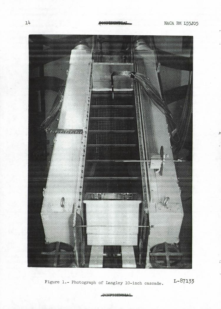
14 OIIFIlrnIIUrLL NACA EM L57JO
L-87133 Figure 1.- Photograph of Langley 10-inch cascade.
N.kCA RM L5JO5 15
63-(6A4K6)06
63-(12A4K6)06
63-(18A4K6)06
I
I
A 10• //
N
/L A2I8b
/ /
.•••
lo
V
20 40 crt
2.0
LE
1.2
PR
8
.4
rel Ice
16
NACA RM L5JO5
Percent chord
Figure 3.- Chordwise load distribution of the isolated airfoil for the A4K6, A2I8b, and A10 mean lines.
NACA PM L5JO
17
---— --;-------------
- - i-- - —
—
C\j co
In rl)
I
--- ----- — o — —
\
- -- ---- _
0
0 LO
4.)
aj
o' LO
0
Cd
2
'1)
Cd
0
Cd
Cc
4.) (Ti
0
4.)
a) bO a3 (a co Cd
Q) Id c5
r—1
0' Wa t 0
b 0
U)
H . 1HL I \ I \\I I I I
PR
I--
1IiI1lIuhT A
S
t M1
_.ui-i!! a....
(c) a 1 : 78° 9:
vex ave S
lOw
am
tuil II-Immmm MENEM - ___ .
18
NACA PM L5JO5
MOEN SEEM I Mammon -U..
NEEME NEEMM I
S
te QI.8°, 9d7.3° (1') QI6.8° 92OC°
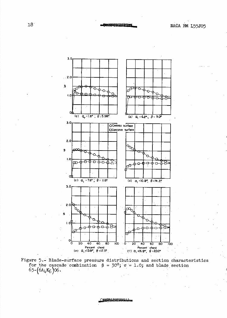
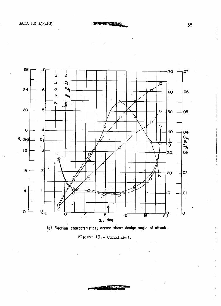
Figure 5.- Blade-surface pressure distributions and section characteristics for the cascade combination 13 = 0; cr = 1.0; and blade section 63- 4K6)06
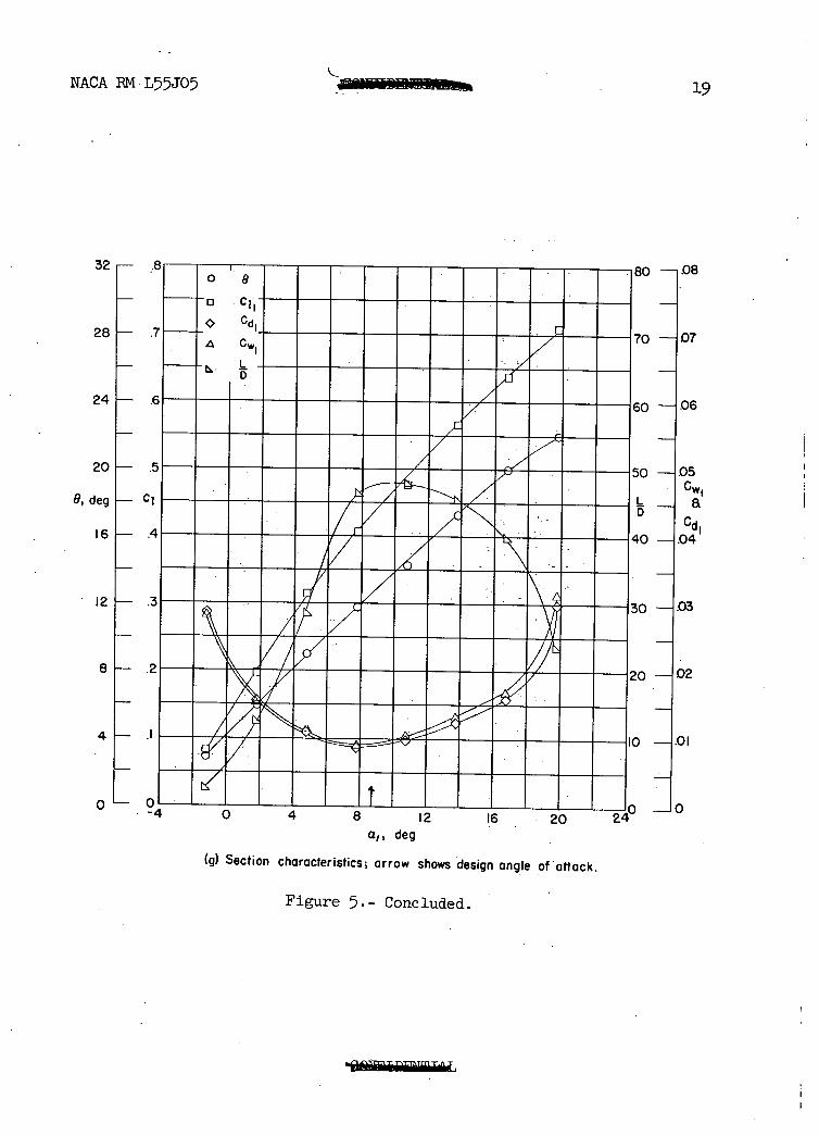
NACA RM L55J05 19
32
2SF-
24
20
8, deg F-
Ci
I6— .
12
8 .2
4
0 0
0 —08
D —107
) 06
) 05
I Cci, ) —1.04
.03
02
0 12 16 20
a,, deg
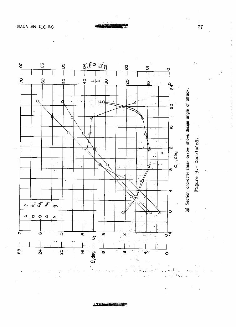
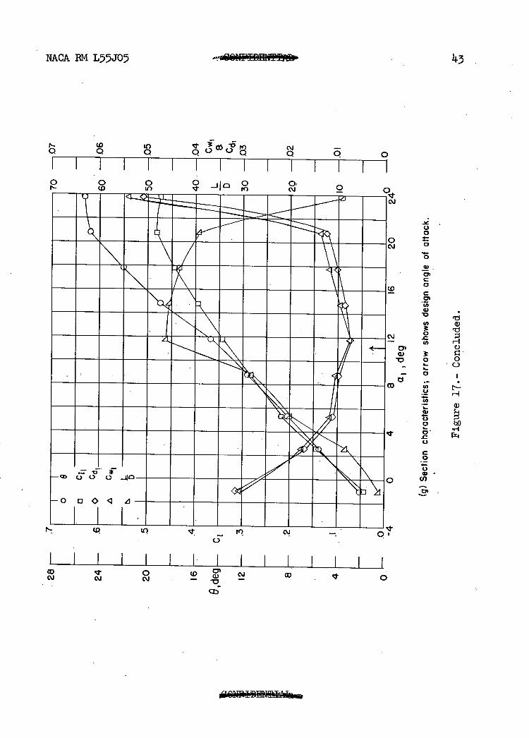
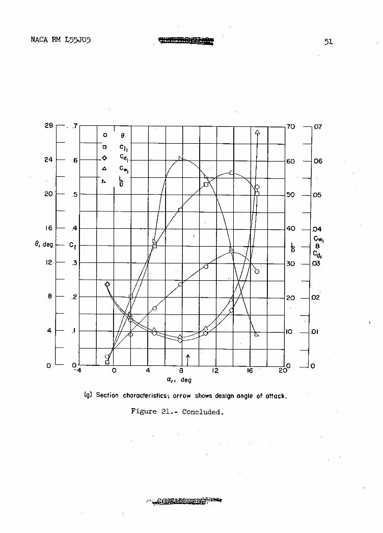
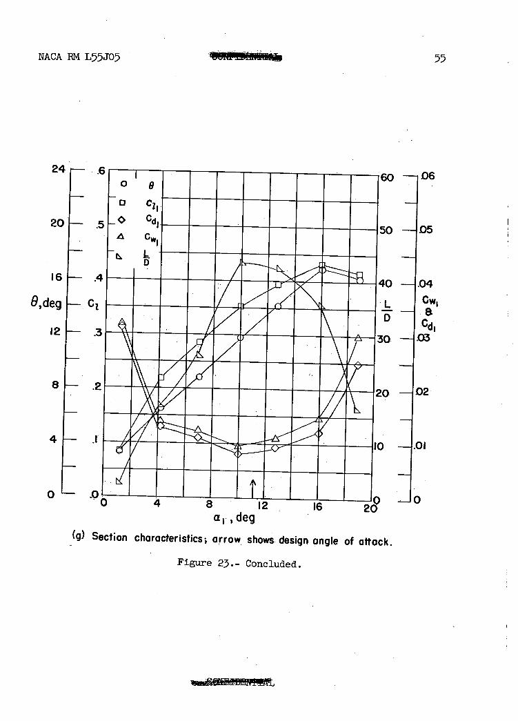
(g) Section characteristics, arrow shows design angle of attack.
Figure 5.- Concluded.
Ru...
2.
S
(c) a 1 =16.8° 9:23.95°
S
(d) a 1 =19.8° 9:26.95°
(b) a 1 =13.6°; 8:2O.79
vex S
ave
RIX
NACA RM L55JO
3
2
S
Liii!J. • • • Percent chord • • • Percent • chord •
(e) a :22.8 9:29.98° • Ct) a :25.8°; 9 :32.58°
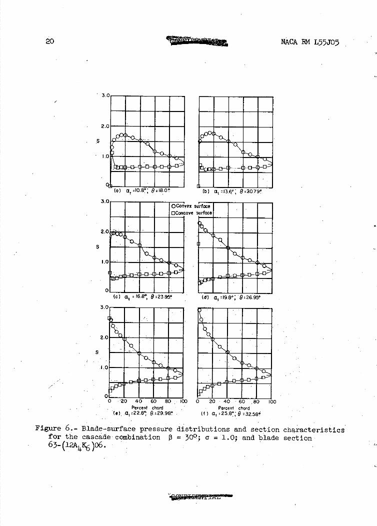
Figure 6.- Blade-surface pressure distributions and section characteristics for the cascade combination 13 = 300 ; a= 1.0; and blade section 63- (12A1 K6 )o6.
NACA PM L55J05
21
o
_G o c1
Cd
.. 7
• .A
----- - -- ---
---- -- -- ----
--.
-
-- -.-
--
--•--- - ---- .--
_-- //--- - III2iI_I/II
_7Z_
0 4 8 12 16 20 24 28 3
40 -
36 -
32 -
28 -
24 - .6
6,deg - Ci
20 - .5
16 - .4
2 - .3
8—.2
4_i
0_.0
00 -.IV,
30 -.09
30 - 08
70 -()7
- 06
Cw1
D Cd1 50 -
—.04
30 --03
20 -02
0 -.01
D -10
Q 1 ,deg
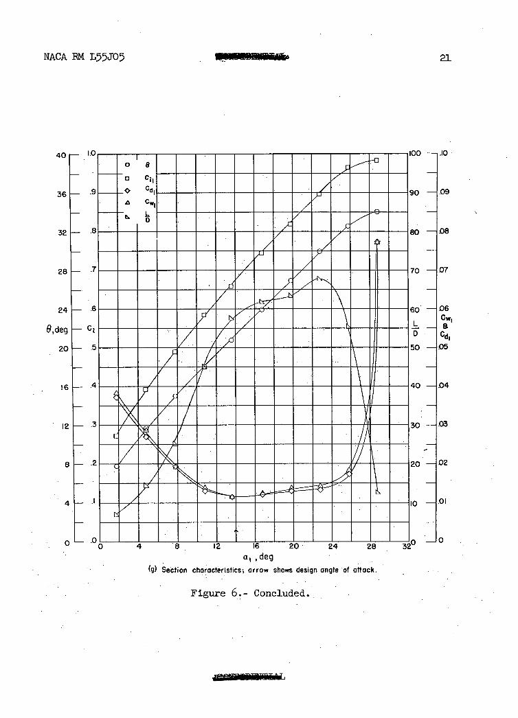
(g) Section characteristics; arrow shows design angle of attack
Figure 6.- Concluded..
3'.'
2
S
(c) a, : 233° 9:33.3° (d) a : 26.3° 9: 36.5
22
NACA EM LJO5
t
2
L
t iii!au
I I I I
(b) a,=20.3*: 9:30.8?
3
2
S
I,
i iI. s MIMMOINW.rolmrs
Percent chord Percent chord (e) a : 29.2°; 9:39.2? (f) a :32.3°; 9 :4
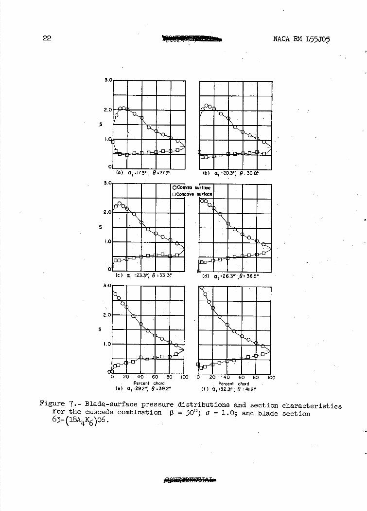
Figure 7.- Blade-surface pressure distributions and section characteristics for the cascade combination 3 = 300; a = 1.0; and blade section 63-(18AK6)06.
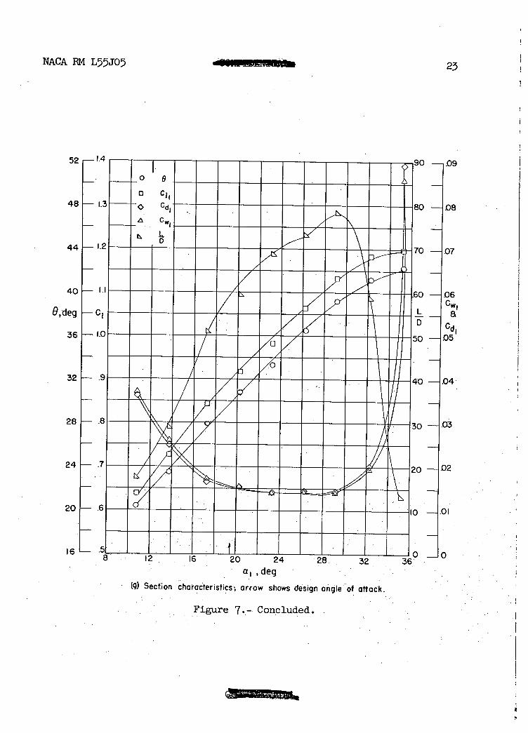
NACA RM LJ05 23
52,-1.4
48 I:
I.:
40- I.
9,-deg —C
36 -1-(
32 -
28 I— .E
24 - .7
20 - .6
16 -
- o l e
c C11
5
IIIIIIY 3
-
Cd---
- 7
7
IL I/ xcl"
IIZIIIIIII 1° - / - - - - -- 2(
12 16 20
) —,.09
—108
—1.07
—1 06 Cwt
a
Cd1 —1.05
I —1.04
—.03
-02
-01
10
a1,deg
(g) Section characteristics; arrow shows design angle of attack.
Figure 7.-. Concluded.
2
S
0 I-
)1 I I I I (a) a :t9° 9:32.5e (b) a 1 :22.3° 0:36.0°
,ex S
ave
3.
2.
S
3
2
S
3
(c) a 1 :2550 9:394°Percent chord
(d) a, :28.50,' 9:4250
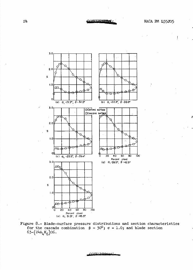
211. NACA RM L55J05
o 20 40 60 80 I Percent chord
(e) a 1 r31 . 5° , 9:4550
Figure 8.- Blade-surface pressure distributions and section characteristics for the cascade combination P = 300; a = 1.0; and blade section 63_(24AK6)06.
N.&CA RM L5J05
56
52 1.4
48— 1.3
8, deg Cl —
1.2
40
36 1.0
32J— .9
25
/ -1.
im
.05
Cw1 a
Cd1
.04
28 L 30 16 20 24 28
3
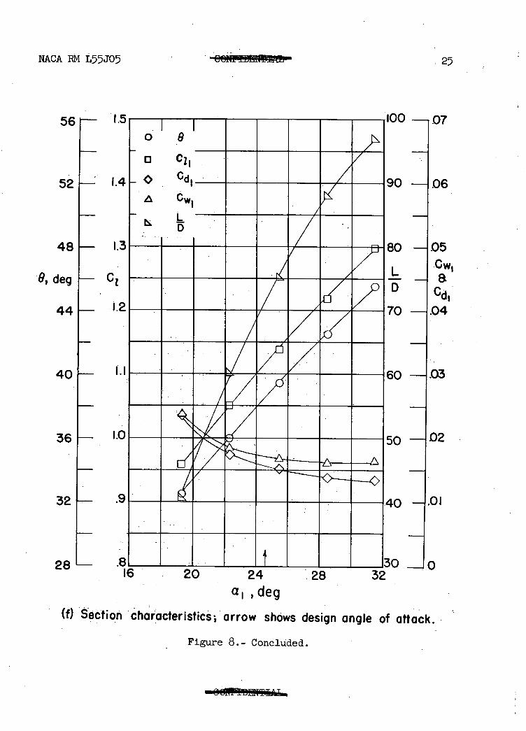
adeg (f) Section characteristics arrow shOws design angle of attack.
Figure 8.- Concluded.
3.0
2.0
10
FII I (a) a. 2.8°: 9 :6.9°
:11 1 1 I I (b) a. :5.8° : 9: 9.8°
(c) a 1 r8.8° 9:129°
3.0.
(d) a , = 11.8* ; 9: 6.0°.
vex ave
• 2.(
S
I•.c
C
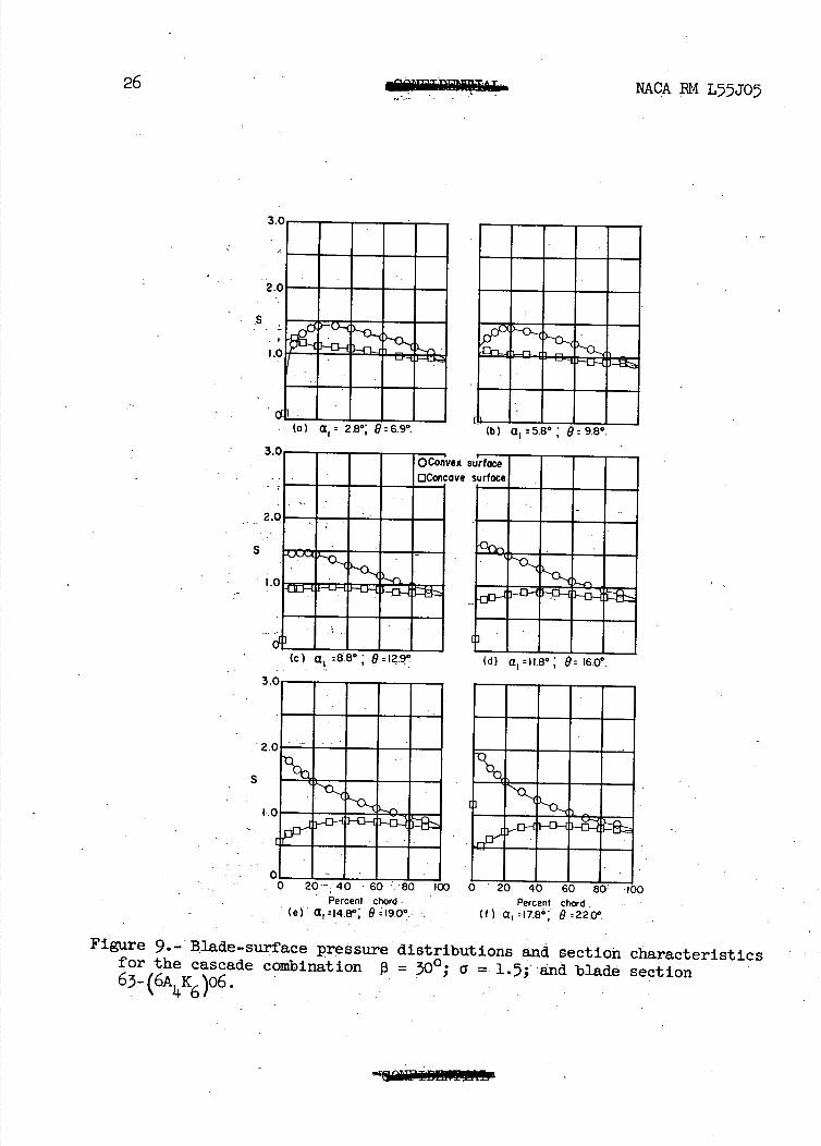
26 NACA PM L5JO7
Percent chord . . Percent chord (e) a: 14.8°: •. (f) a 1 :I7.8 9:220°.
Figure 9.- Blade-surface pressure distributions and section characteristics for the cascade combination 0= 300; a = l.; and blade section 63-(6A Jc6 )o6. .
11. c.J
U 0 0
0 o CJ
C 0 C
- 0 (A a.
rd - 0 H
Q) .. L.. C) V 0
-
rvZ t a. 0 I-0 o •-i C 0 U
C/,
D
NACA RM L5JO
27
N- Q
W 0
tO coO
- Q Qo Q Q
I I I I I 0 C) 0 0 0
I I •.I 0 N- tO -
(c) a 1 r16.80 ; 826.I (d) a9.8°; 929.I0;
-. 0 Convex Surface OConcave surface
S
MEMO
I
MOMM
II-II ME
II I---o?I AMEN
28
NACA IRM L55J05
3.0 - -
(a) a.iO.8: O:197!LI I I • I I
(b) a l3.8 622T7e
Percent Chord Percent chord - (e) a, 22.8; 9 r3° f a1 r25.80 ; 9 35O
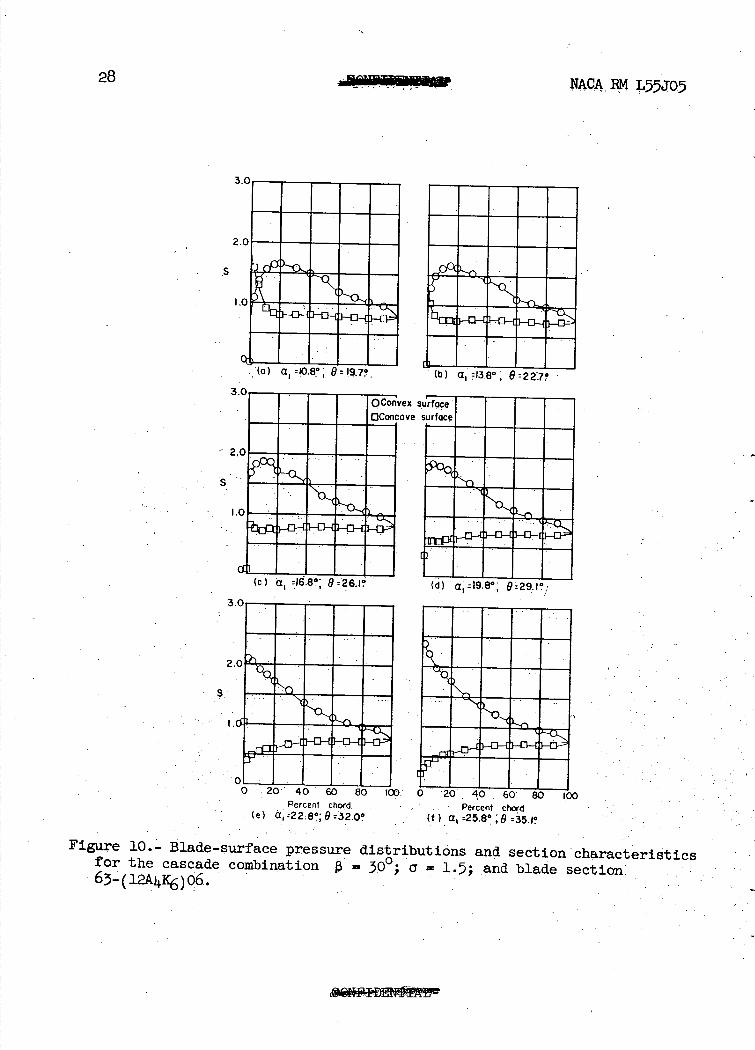
Figure 10.- Blade-surface pressure distributions and section characteristics for the cascade combination 0 = 300; a = 1.5 and blade section, -
-63—(124c6j06. -
NACA RM L55J05 DJ!LAL 29
44-1.0 ---------------_ _80
40 —
36—
•9
-
.8
0 9 a C11
C1 -:1__
-
—08
—07 7270 ---
•_ 7_
/60
- /_7/O6
32— .7-
--- -
5O
O,deg_ C1
__ ___
/ ..L _a
05
___/ CdI
-
24- -5— X I -- --H- -
20-
-
16— 10- Oi
2 .2I12 4 T8 32
- 0 a1,deg
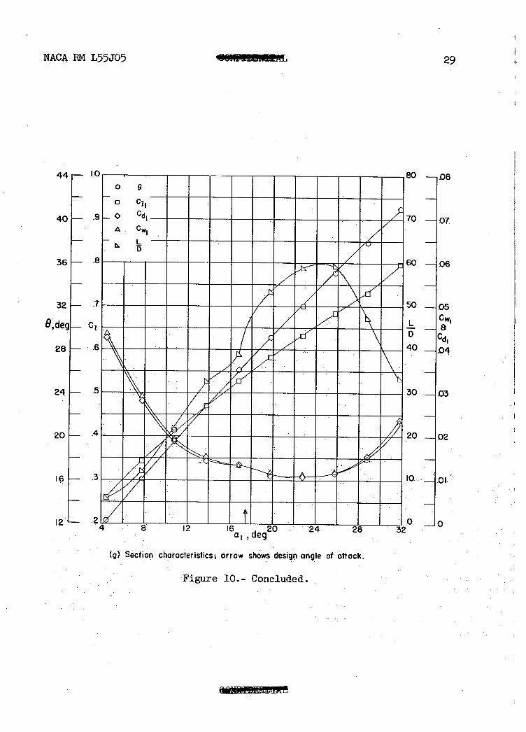
(g) Section characteristics, arrow shows design angle of attack.
'Figure 10.- Concluded.
0
30
NACA EM L55J05
Is FM
I .1 1 (a) a - =18.8*: 9z32.70
L. I I I (b) a. r21.80 Pr
S
S
Percent chord Percent chord (e) a 1 r30.8°;6r44.2° (f) a1r33.8;9473,
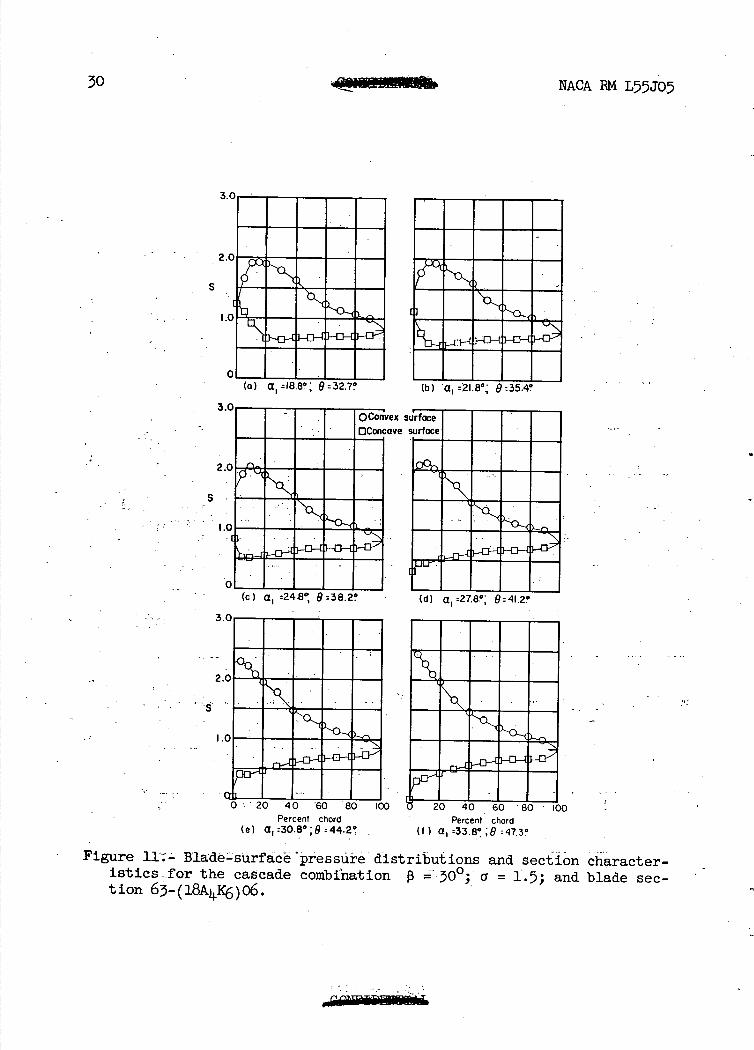
Figure 11;- Blde-surfäcèpressüre distributions and section character-istics-for the cascade combination P =30°; = 1.5; and blade sec-tion 63-(18A4K)o6.
NACA . L5JO31
(0 0 c%J -
Q 0
c
I-, a
a
.4-0 w a, C a C a, U, 4
-a
(nrc; rd
-DoC)
. H U) o 4-U)
cn
,-
va W. N LI 11111111 III
c.., OD. c'J. . .. OD U) -
D, • o (0- -- N) N) CQ
• --
EF'b' NN
S
3.('
2 .0
S
I.c
C L)
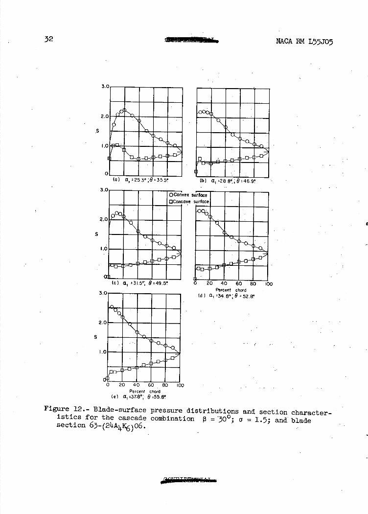
I IH a. r2530:93550
(c) a 1 : 31.5°; 9:495' U 0 40 60 80 100 Percent chord
(d) a -34.8-: 9 52.Er
2,
S
I.
oj a1:eso;46.9
vex
ave
32
NACA RM L5JO5
Percent chord (e) a, _37.8*' O:55.8
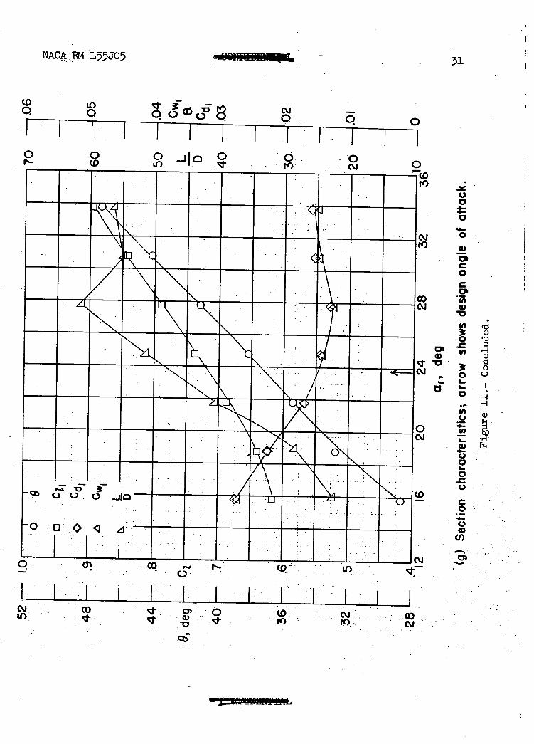
Figure 12.- Blade-surface pressure distributions and section character-istics for the cascade combination 13 = 300; a = 1.5; and blade section
.2
1.1-0
I.o 8
clI_
C:
WI
- L D
.
.7
5
:
_
.9 . . 4
3'
.7 "Nd Ei /
2
.6 ____ ___ . . . ___ . IC ___ .
28 .32 36. 40 0
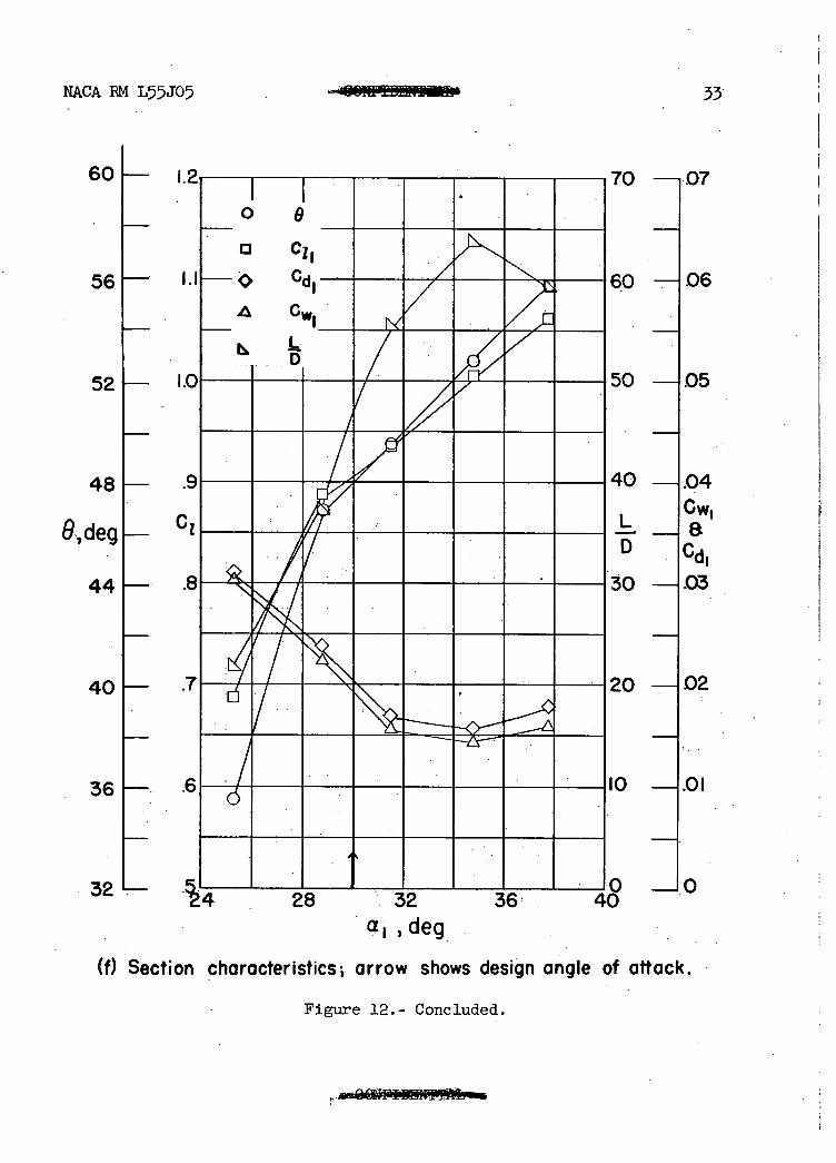
NACA EM L5J0
60 1— I
56
52-
48-
9,deg - C
44—.
40-
36-
32.—
33
—.O7
o -- .06
0-05
0—.04 Cw1
D Cd 0 —.03
0-02
—.0I
—0
a, deg
(f) Section characteristics arrow shows design angle of attack.
Figure 12.- Concluded.
34
NACA RM L55J05
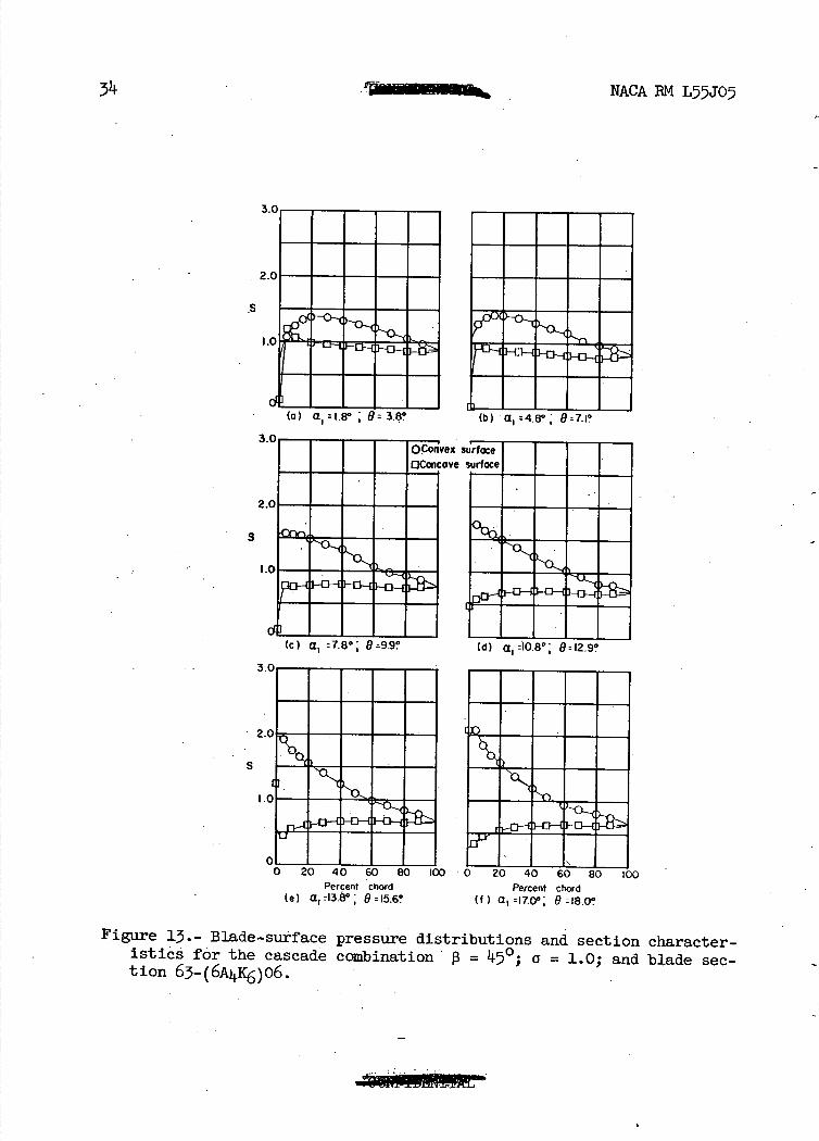
3.0 - - - - -
2.0 -
S -
1 .0 '• •°=
C - - - - - (a) a 1 =i.s° ; 9= 3.8°
3.0-QConvex
OConcave
2.0 - - - - -
S
--(c) a1 =7.80 9=9.9?
2lIUI Ms". .55 M
EN U-16M.MM
LMMM 3 ur
2
S
Percent chord Percent chord
(e) a 1 =13.8°; 9=I5.6 (t) a 1 =17.0, 8;18.0*
Figure 13.- Blade-surface pressure distributions and section character-istics for the cascade combination = 450; a = 1.0; and blade sec-tion 63-(6AC6)o6.
.1
•
.5
.6-0
o 8
O C1
Gd1
• cwr
T JIM
61
-
/ \
"T1 110
—4 8 12-
) -107
—1 06
-1.04
at Cj1
1-103
—102
7
24
20
16
deg
12
8
4
Li]
NACA EM L55J05
35
a,, deg
(g) Section characteristics; arrow shows design angle of attack.
Figure 13.- Concluded.
(C) a, : 13.8°, 9:199°
2
S
2C--
S ---------.
O— -OH —0— —O
- (a) a,:8.8°, 9t4J°
3.0T--FO-Convex
OConcave
RR
NACA RM L5JO5
rWAIIl....
i•i'ui
p1...
S
Percent chord Percent chord (e) a, r 19.50 ; 0 : 25.0° (f) a,=22.6- t7=27.3-
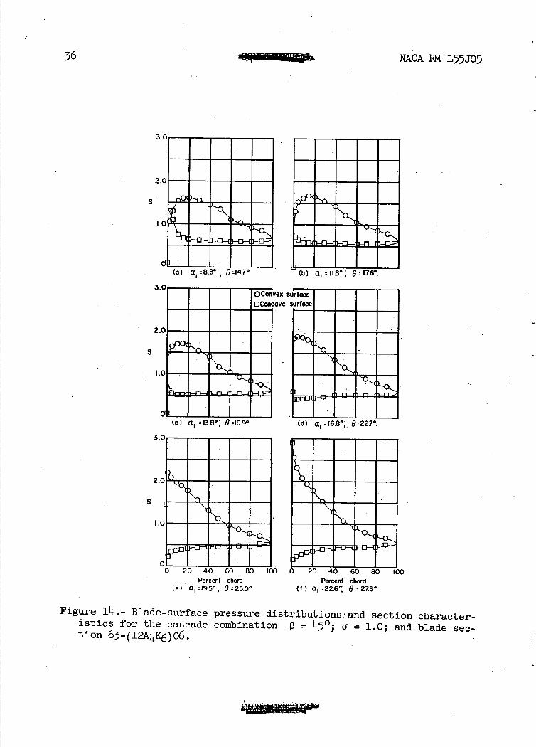
Figure 14.- Blade-surface pressure distributions.' and section character-istics for the cascade combination 0 = 1150; a = 1.0; and blade sec-tion 6-(12A4c6)06.
NACA PM L55J05
37
36 -
32 -
28 -
24 -
20 -
deg -
16 -
12 -
8—.
4—.
0—.
-
-
7-----
I 0 8 a C11
.A Cw1 L D
90
N
- - - - -
\"O,
-- ti
- - - -
----70
-
-
7------
7 T/--
-
4 40
2 ^-20
1 10 6 20 24
a,, deg
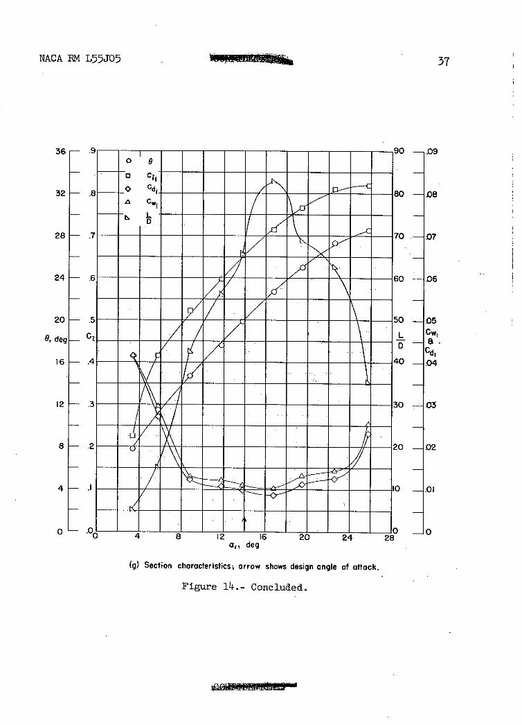
(g) Section characteristics; arrow shows design angle of attack.
Figure lii. .- Concluded.
-.09
- 08
07
-06
-05 Cw1
- a. Cd,
-.04
—.03
-02
-.01
—0
3.0
2.0
1.0—
OL I I I I
I I I I I
(a) a. is.e°; 8=247*
(b) a. r18.5° P:276°
(c) a 1 20.5° 925°. (d) a1 23.3° 932.I0.
2
S.
vex
ave
38
NA.CA EM L55J05
2.0
S
1.0 ir
0 Percent chord Percent chord
(e) a, =26.6*' 9:34.30 U) a 1 ;29.2' 6:36.0°
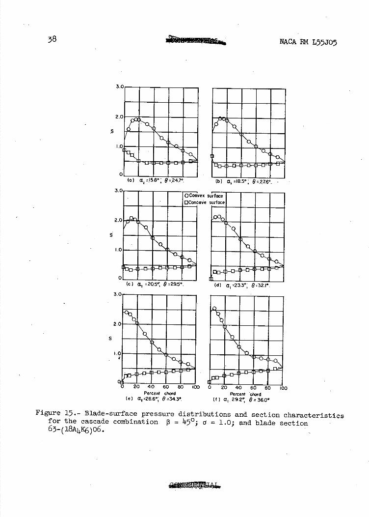
Figure 15.- Blade-surface pressure distributions and section characteristics for the cascade combination 13 = 450 ; = 1.0; and blade section 63-(18A41c6)06.
90 —i06
80 —.05
70 I•°4 0w1
D JGd1 60 H.03
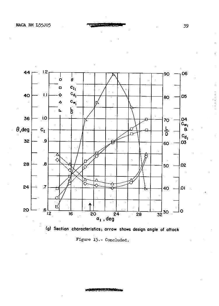
NACA BM L55J05 39
0
0 C11 —G Cd1_
A
- L D
36— •L0 70 0deQ[_ Cl.
321— .9
281----- .8 50 —02
24— .7 U/ 40 —.01
20L_ .616 20 . 24 28 32 30-0
a1,deg (g) Section characteristics; arrow shows design angle of attack
Figure 15.- Concluded.
44i— . . 12
401— Ii
(b) a, 28°, 9338°.
Percent chord (d) a, :28.8*,- 9 =39.8*.
C
(c) a, :258° 0=370*.
2.
S
I.
vex
ave
0
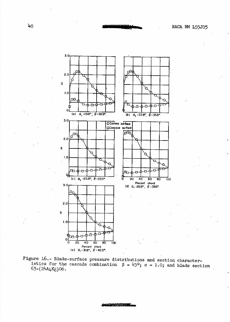
40 NACA EM L5JO5
3.0
2.0
S
MKKI
S
Percent chord (e) a,3I.8°, 642.0
Figure 16.- Blade-surface pressure distributions and section character-istics for the cascade combination $3 = 450; a = 1.0; and blade section 63_(24A4c6)o6.
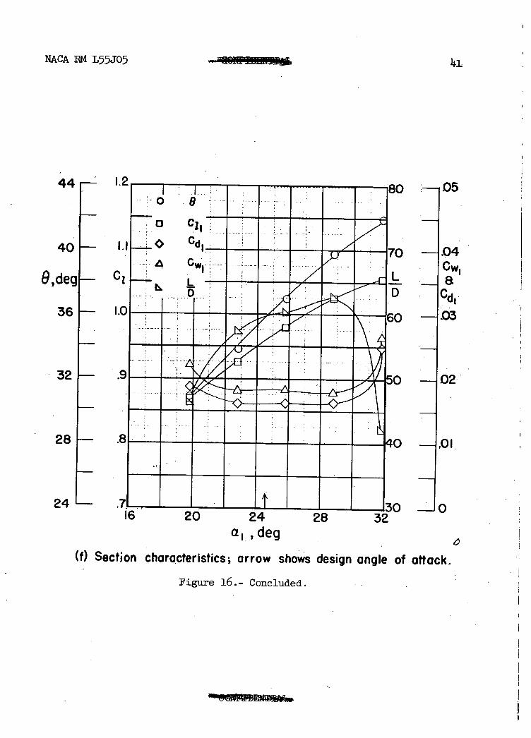
NACA 1M L5-5J05 Im
11.1
1.2I : BC
8 H H
40— Cd1..7c
c, i &d
........._ _ /: _
1.0 ______
32 - 9___ ___ 5C < A I
28— .8
05
.04
a Cd1
.03
02
24 .71, 1 I. . I I T I I I 130 -Jo 16 20 24 28 32
a1,deg
(f) Section characteristics; arrow shows design angle of attack.
Figure 16.- Concluded. . .
I II (b) a. :88° 9rII.6°
PI 11.400,00
MENEM
El...
3.0
2.0
10
JJ III (a) a r° 9:p7'
(c) a ii.s; 9I4.7°
S
ex
ave
S
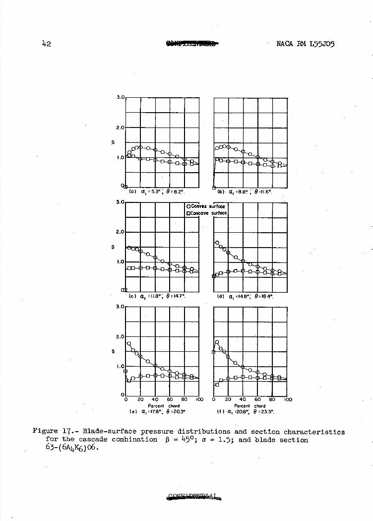
42 IU dI!Ut N&CA RM L55JD5
- Percent chord Percent chord (e) a,= 17.8 9 20.3° (f) a :20.8', 9 =23.3g.
Figure 17.- Blade-surface pressure distributions and section characteristics for the cascade combination 13 450; a = 1.5; and blade section 63-(6A1Ic6)o6.
NACA BM L5JO5
N- W IL) Q 0 0 0 0 Q 0 I I I I I I • I I I I I I I
o 0 0 0 2' N 2 0 - In
11.3
CD v ('J 0.)
0 CJ a)
co-
cJ CD0
a) Id
H C) r. 0 Q
N-H
a)
.v-lxi
(c) a1 : 176 8=.25.9*.
S
NACA EM L55J05
-
NONE AIMEM some S....
7i_ . ^.'mNONE lU
S
• - - - -
NIEMEN
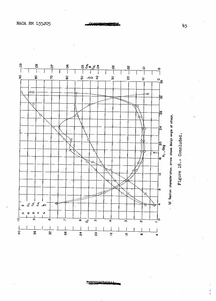
(e) a 1 :2320; 9r315° (f) a 1 :29.60; 9 :37°
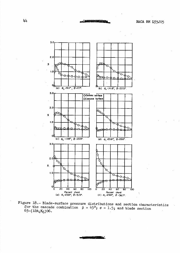
Figure 18.- Blade-surface pressure distributions and section characteristiôs for the cascade combination 13 = 450; a = 1.5; and blade section 63-(12Ac6)o6.
0 !I
NACA RM L55JO
I-5
co Q Q 0
CD
0 in 3F CM -
0 0 0 I I I. I I I I I I I L. I 1 P1
0 0 a,
0 0 CD
0 -Jja 0 9 2 -
ri
U 0
0
0
a, 0
C Q) 9 'a a,
H U) C)
.0 0
o I
co H
—1
0 P4
)O C)
o DO I I I
C
0) a,
C) cu -
I I I I I I I I I I I I I I I I I 0 CD 10
co TI)
a,
CM CM0 CM
CD CM co
S
'ex $
]ve
WE
I I I I (o) t rtAR° Q3046
go:
(C) a 1 :248w 9r365°
3
2
S
NACA EM L55J05
No 'Ii... .U.. •UUR
1•] Percent chord Percent chord
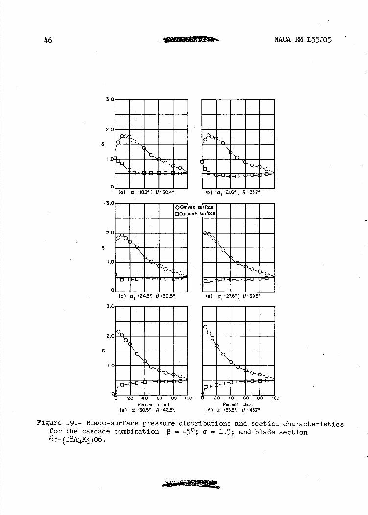
(e) a:30.5° , 9425° (f) a :33 .80 , 9:45.7°
Figure 19.- Blade-surface pressure distributions and section characteristics for the cascade combination 13 = 450 ; a = 1.7; and blade section 6-(18AIC6)o6.
NACA 1RM L55JO
".7
LI) -ic-5) (J - o 0 0 QO OQ Q 0 0 II IIIIIlIIIIII o 0 0 0 -AD 0 0
LO in cJ 2 qT
000
0 0 01
1.)
(0 0
in
0
CM C in 0
C Di
.u) a,
•0
U, OD
c.J 0
a) U) •0
0 -
. 0
c'JU) C,
U,
a) 0 0 o
Cs'
C.,
C •0
U)
sp
a,
C) 5:: 0
C)
H
I I I I I I I I I I I I I I IN Ci co U, In c
('J Cti It)
OD qt
0 It w
1.0 in
CJ in a)
0
.0 }-
Of I I I I
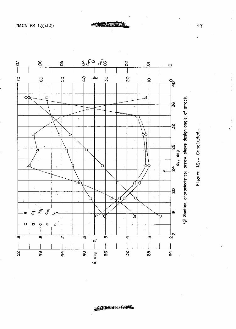
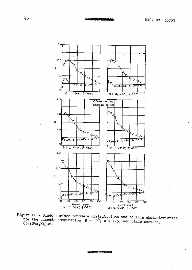
(a) a24,8°: 9396° (b) a r278°; 9r42.7
S
Li]
(c) a1 31.1° 9 46.8°. (d) a 1 33.8°, 949.4°.
ex ave
S
48 MWOMM NACA EM L55J0
S
I—. 0
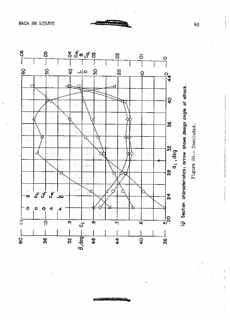
Percent chord Percent chord (e) Q 1 r36.8°, 052.0° (f) 39.8° 955.2°.
Figure 20.- Blade-surface pressure distributions and section characteristics for the cascade combination 0 = 47; = 1.5; and blade section, 63-(24Ajc6)06.
NACA RM LJO5
14.9
CD. LO 10, f°c3' c'J - Q
0 Q 0 IIII J•I I • Iiii I-I CD In 0 •0.
2 os,. . 1 I1 111111111 I.cj.
C.) 0
0 0
w
C 0
CD C
U, a Q 0
H
C) 0
OD
c.J roc,
a)
- 0
U, C-,
CsJ .U, x1
C.) 0
0
0.1 C.)
C 0 4-C-)
U)
Q
701 — cp U) -
I . i Ii F I HI] CD 0
CDCDU) U) -o
).
0
OL (o) a1
3.,'
2.
S
(c) a, n4.8°; 9
iex
ave
rNE•i MEN ME
NONN I
S
II ii
NACA EM L55J05
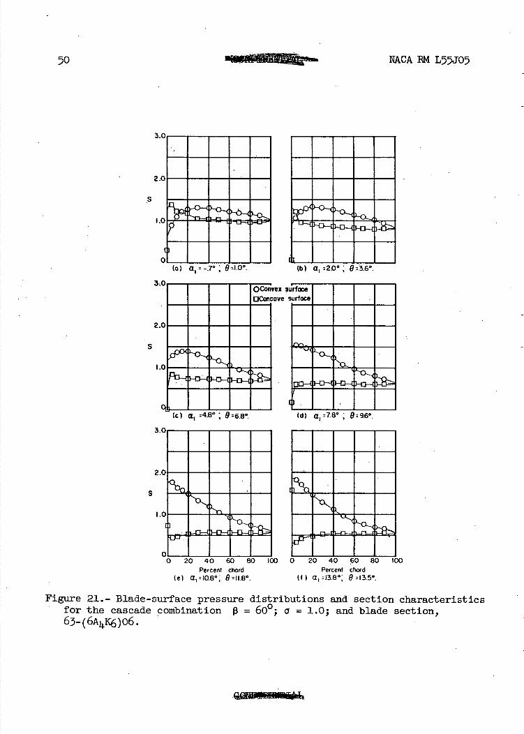
Percent chord Percent chord (e) a,=10.86 ,* 19 =11.80. (f ) a,=13.8*," 9=13.5'.
Figure 21.- Blade-surface pressure distributions and section characteristics for the cascade combination 13 = 600; i = 1.0; and blade section, 6-(6AK6)O6.
161— .4
deg ._ C1
12 I- .
40
I Cw1 k 0 i,.
30 —1.03
NACA IM L55J07 51
28r— . .7
24 F— .6
o a
o Cl,
C1
.A Cw1
70 —.07
60 —1.06
20H- .5 50 —1.05
8 I- .2
20 ---A 02
4F— .1
I.— K
O L_ 0L
-4
I I I II I I I I I 10 ..........J0 0 4 8 12 16 20
a,, deg
(g) Section characteristics; arrow shows design angle of attack.
Figure 21.- Concluded.
a.-. I I I
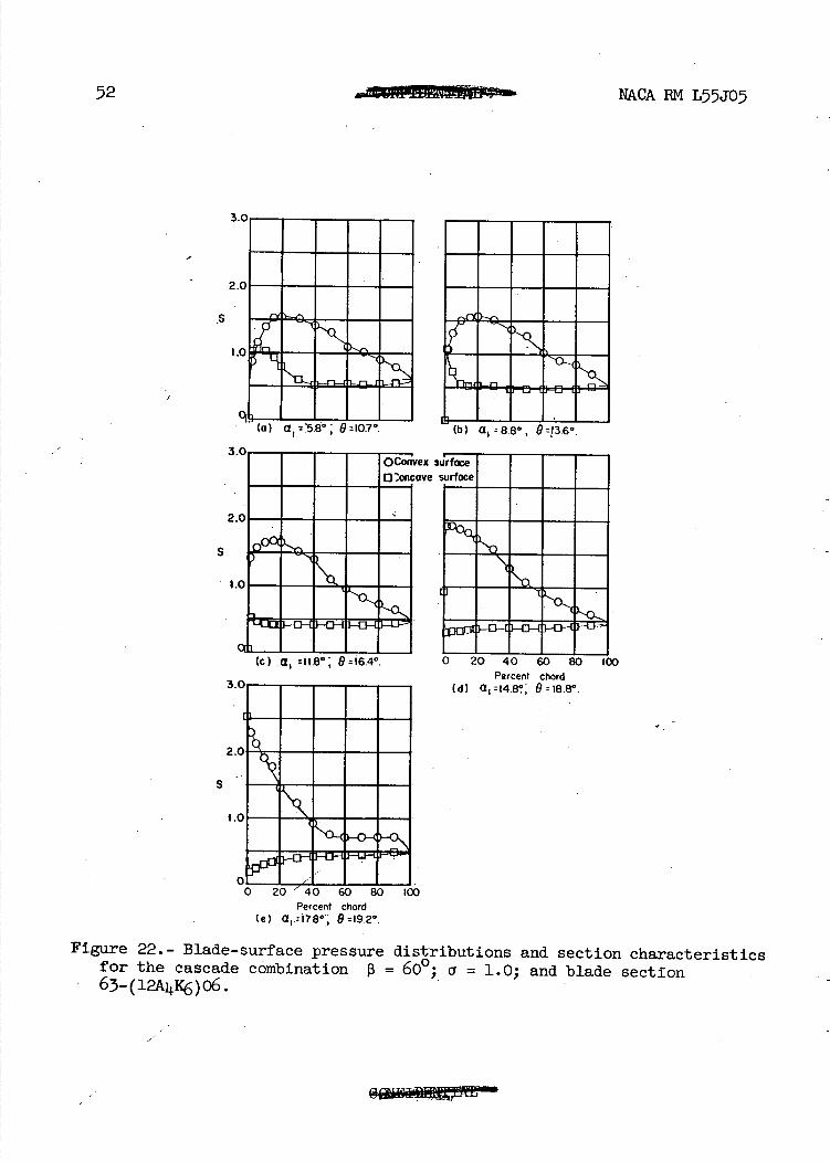
(a) a .5 g°: 11107 * (b) a, 88°, U J3.6°.
,ex s
ave
(c) a, 11.8°; 9I6.4°.
S
3.0-
2.0-
1.0
Percent Chord (d) 9r18.8°.
NACA RM L55J05
S
Percent chord (e) a, = 17.8*',' B I9.2°.
Figure 22.- Blade-surface pressure distributions and section characteristics for the cascade combination = 600 a = 1.0; and blade section 63-(12K)o6.
53
• I I -Th 0 9
/ .D C1.
0 Cd 1 — . - - -
A Cw1 -
L D
- - - -
11111li7,
- --- -,-- - - 14,
• J - - 3 I . -ci--•ii77 E1I1 12
—Ic
- 4 8 12 16200
NACA 1M L5JO5
48 i— Ld
44 1.3
40 1.2
36 — . 1.1
32 - 1.0
O,deg - Cz
28— .9
241— .6
201— .7 161-- .6
12
8 .4
—1.09
—108
—107
H06 Cw1
—Ia )
Cdj —105
) —1.04
) --J02
a, deg
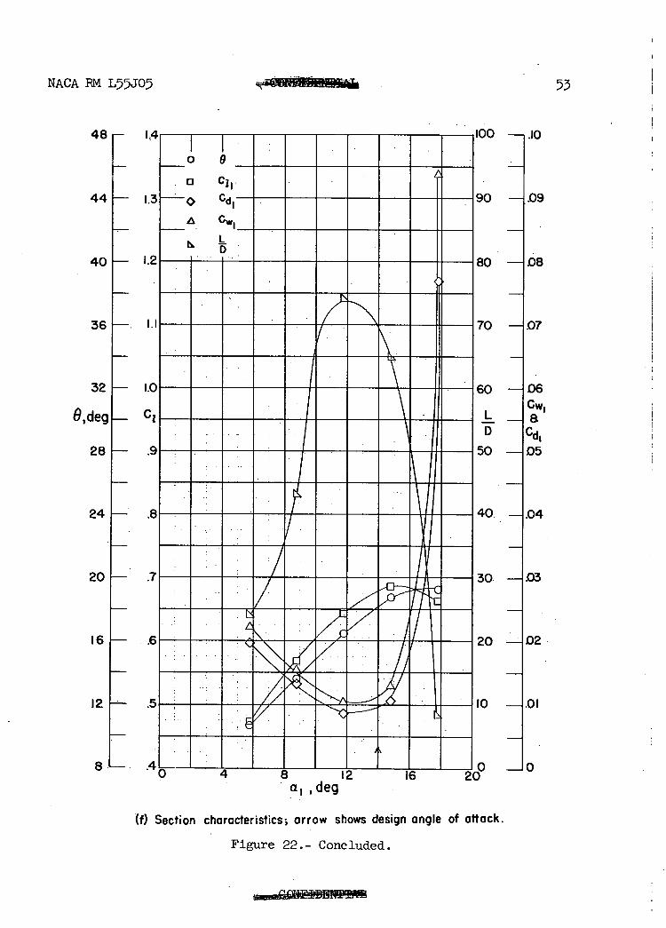
(f) Section characteristics arrow shows design angle of attack.
Figure 22.- Concluded.
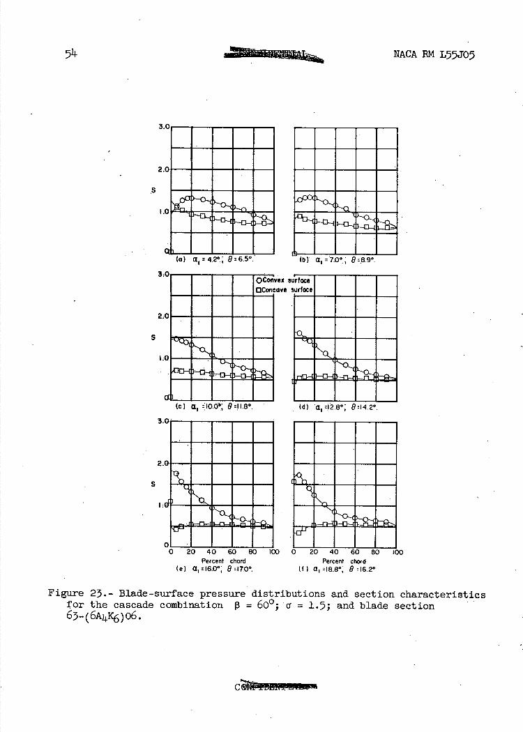
to) a 1 427, Urb.3.
(c) a1
3
S
NACA RM L7JO5
3.0
2.0
$
1.0
1 I (b) a. = 70° 19=89°
ffm ^ U.... N N I R.I., 0 0 0 - b7o.0- I W.. . •
NINON
2
S
01 0
0 Percent chord Percent chord
(e) a, =16.0*,' 8=17.0°. (f) a, =18.8*, 8 =16.2*
Figure 23.- Blade-surface pressure distributions and section characteristics for the cascade combination 13 = 600; a = 1 .5; and blade section 63-(6A4K6)o6.
60 —i06
50 —J05
0 IO4
LCw D et
d1 o. —1.03
o. —.-J02
—1.01
NACA EM L55J05 55
O,deg j__
C
12L
20
[:]
24r—.
.5- •
4—
o
• n C11.
C
A
•/
4k-
ØL. ç
a1,deg
(g) Section characteristics; arrow, shows. design angle of attack.
Figure 23.- Concluded.
0 4 8 12 16 C 2n
(c) a1 : 13.8° 1 9:198°
S
56
NACA BM L55J05
3.0 - - - -
2.0 - - - -
1.0 HEM
- - - (a) a 8.36 R1I4°
3
2
S
r....
00 i
MEN MEN.6"ah"N. I-
o 20 40 60 80 Percent chord
(e) a, z20.I * ; 926.3°.
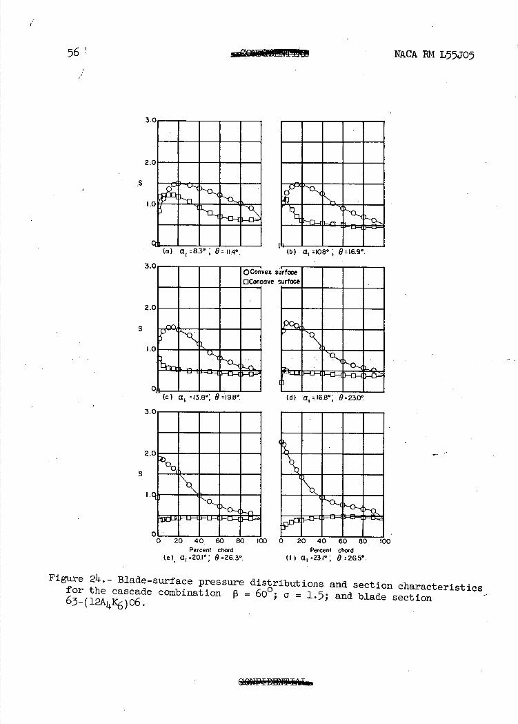
Figure 24, Blade-surface pressure for the cascade combination 13 63_(11Jc6)06.
00 0 20 40 60 80 100 Percent chord
(f) a, =23.1 0 9:2.5°.
distributions and section characteristics 600; a = 1.5; and blade section
o 9 32 .6
28 .5
24H .4
0,deg— Cl
201— .3
16 .2 L 12 .1
MACA RM L55JO '7
60 —i.06
50 —L05
40 H.04
L ICwi --Ha D lCd1 30 —j.03
20 ---A 02
L_ .0 1 I .1 I I II I I I —JO
8 12 16 20 24 a1,deg
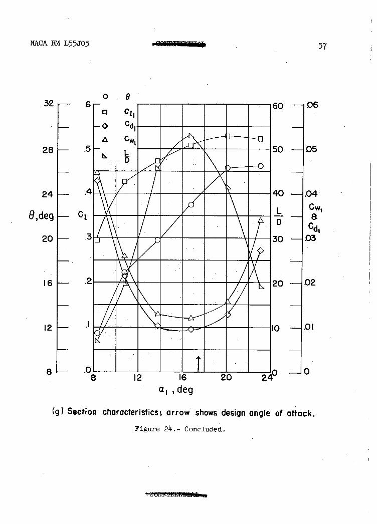
(g) Section characteristics; arrow shows design angle of attack.
Figure 24.- Concluded.
1-
MACA BM L5JO5
6,d
/
7 -- ----------------/
36-
o 63-(6A4K6)06 063-(12A4K6)06 063-(18A4K6)06 L63-(24A K6)O
as
----k- /--- ---------
2 /
/ ?IIIIIIIIIIIIIIII 4
C)V lb ib
a 1 ,deg
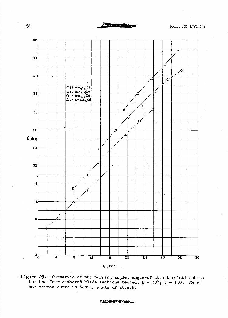
Figure 25.- Summaries of the turning angle, angle-of-attack relationships for the four cambered blade sections tested; 0 = 00; a 1.0. Short bar across curve is design angle of attack.
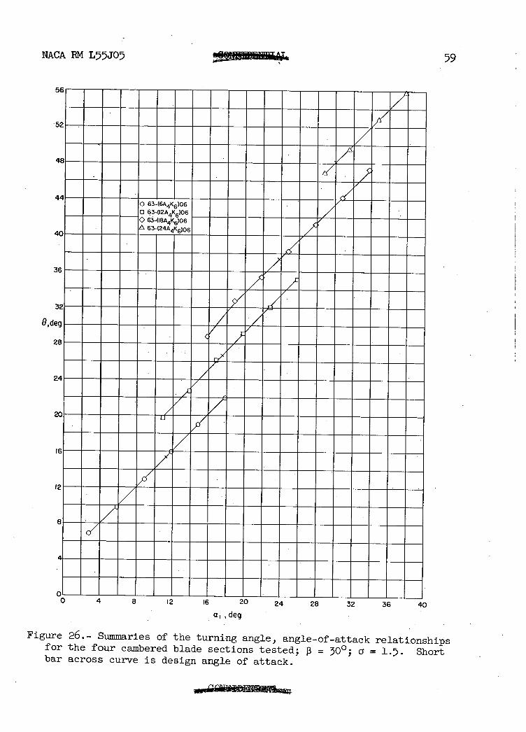
NACA BM L55J05 59
UO
52
63-(6A4K6)06 63-(12A4K6)06 63-(I8A4K6)06
40
36
32
8,deg
28
24
12
8
0Iz lb zu 24 28 32 36 40 a, deg
Figure 26.- Summaries of the turning angle, angle-of-attack relationships for the four cambered blade sections tested; 13 = 00; a = 1.5. Short bar across curve is design angle of attack.
RN
NACA EM L55JO
O,d
-
- - - - - - - - - - - -
40 — _ - -
36- - - - - - - - - - - - -
- -
_7/ :7 ---- - -
63-(I8Ag)06 - - - 0 63-(12A4K6)06 - - - - - -
- - -
2€L 63-.(24AK6)06
All 1 2 --_
eg
-
-
- --
- - - -------- --
16 -
12- - - - - - - - - - - --
8- - - - - - - - - - - - - - -
---- - -
Go—8 12 16 20 24 28 32 36
• a, deg
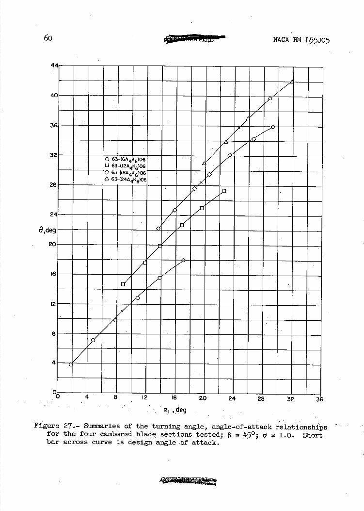
Figure 27.- Summaries of the turning angle, angle-of-attack relationshi'ps for the four cambered blade sections tested; JO; a = 1.0. Short bar across curve is design angle of attack.
NACA 1M L55J05 61
52 I-
48 I-
iolm63-(24A4K6)06
O,d 52[
!4F--
12
8 F 4!-
a1,deg
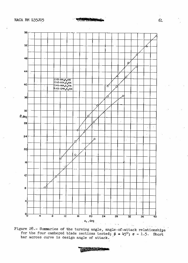
Figure 28.- Summaries of the turning angle, angle-of-attack relationships for the four cambered blade sections tested; = 450; a = 1.5. Short bar across curve is design angle of attack.
62
NACA RM L55J05
(D (D
CIJ
0
L) CQ co csJ -
-D
-o 0
lq-c'J
0 ('J
0) c'J a) -
t
a)
(1)0
r1 (I) co
(1)0
00 r1 Cd
Cd Hcd a),a
00
-pci) -p
Cd
cIo 0• PH
a) Hit
Cd
-0 a)o H\0
1 it cd
bO
•H (I)
-H -p-p
0• a) a)
-p Cd a) -p rd
OCdcd H
Q) 0 -H 'rj
a)a) Cd -H
(1) b.0
ct
I bO • 0 -H
cJ\ (I) ('J -p a)
rd
i Ci -H bO
-H Pri
62 -
NACA RM L55J05
20
16
• 2
6,deg
8o 63-(6A4K6)06 o 63-(I2AAKC)06
4
CI 1 l_. I I I I I I
_4 0 4 8 12 16 20
a 1 ,deg
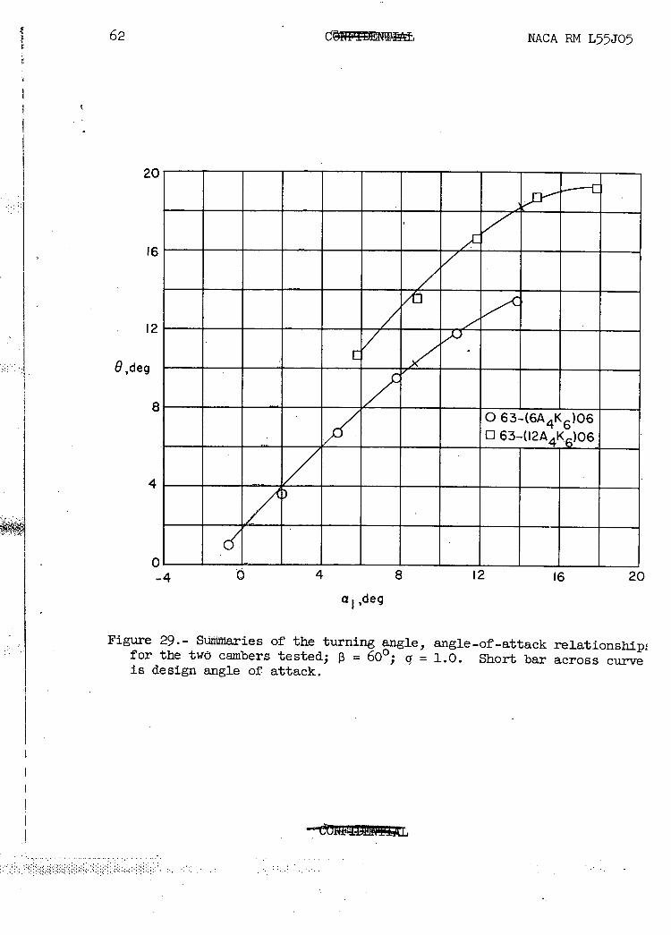
Figure 29.- Summaries of the turning angle, angle-of-attack relationship,, for the two cambers tested; = 600; g = 1.0. Short bar across curve is design angle of attack.
4
4/ _
o 63-02A4 K6)06063-(6A K6)06
/1
6__
.7/c' 2
/ 8 7 _ 4
0 4 8 12 16 2fl
20 0
2
2
0, de
NACA EM L55J05
63
a,, deg
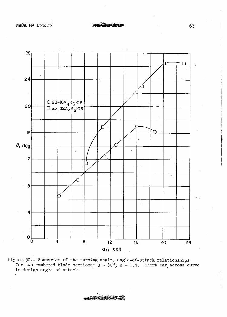
Figure 30.- Summaries of the turning angle, angle-of-attack relationships for two cambered blade sections; 3 = 60 0 ; a = 1.5. Short bar across curve is design angle of attack.
30
0
D6-
I2 6 - LI8 ____
441<6
Ref. I
2
\
B
E I
30 40 50- 60 7(
a-
2
6!i. NACA RM L55J05
a) -a)
C 0
C
a) 0. 0 ri
deg
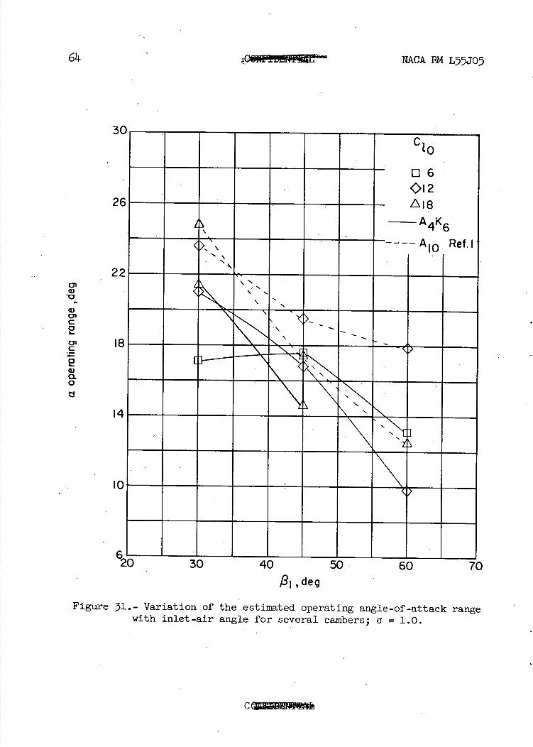
Figure 31.- Variation of the estimated operating angle-of-attack range - with inlet-air angle for several cambers; a = 1.0.
30
04
€__ 06
- 012
A 1
t24 4.-A K
2 - - - A Ref. I
10
8
0
30 40 50 60 7(
F
S.
Ac
NACA PM L55J05 65
w
V
Q)
On
C 0
C I
deg
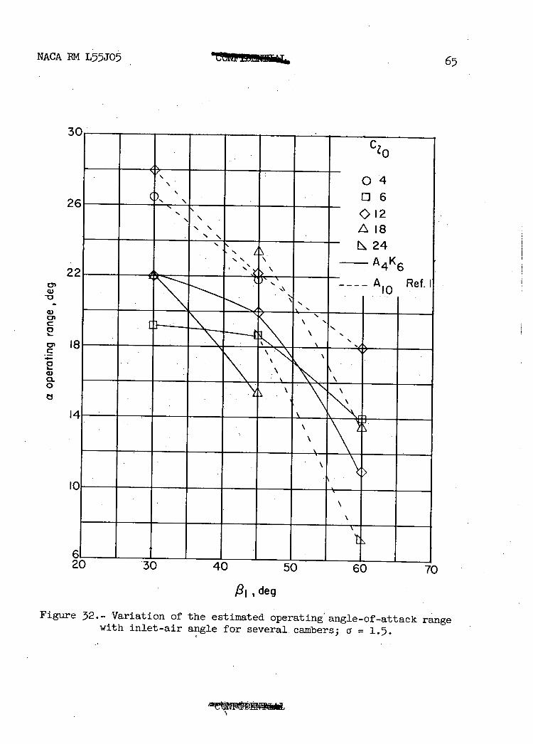
Figure 2.- Variation of the estimated operating ' angle-of-attack range with inlet-air angle for several. ca.mbers; a
a —a. M4 fl 6 A10 0A4K6 - 0A10
NACA RM L55J05
6 a
60 0 0 45° 0 300 A
- i 0
aA 4K_ a
9A4 K6 -
2
ONU
(a) o-:I.O
CIO. (b) a- =15
Figure 33.- Difference between design a. and e for the 63-(C10AK6)06
and 65-(c10A10)10 blade sections.
(c) R :272,000. 3
S
L M
Sol I S "
2
S
I.
-N..
NACA PM L55J05 67
sbti::: (a) R :159,000.
U ENEM 'u..
-N- JI:1I.I.I._
Percent chord Percent chord
(e) R 346,000. f R :385,000:
Figure 314._ Blade-surface pressure distribitions at various Reynolds num-bers for the cascade combination 0 = 450; a = 1.5; and blade section 6-(12A}(6 )06; a. = 11.80.
CM
0
ON III
r1)
W
H 0
a) tz
4.)
(0 a)
H r1
0
P4
0
P. qco
rN
68 MACA PM L55J05
0 r()
K II
d
..' 4.)Lr\
0II
(0 o b
.4.) •. (00 •rlIf\
4 a)
4.) II C) Cd ax
..'
(JO)
4.) 0 a) (0
0
51 0
•rl
-'-I
Fe'
1
(70 c
0<
c%J
Wil
csJa cj
('J
-o
cj
(d) R . =313,000.
2
I, 0I__
NACA RM L5JO5
s1c1114 (a) R 159,000
3
2.
S
(c)R :272,000. 3.0,
(b) R = 220,000.
ex we
20 40 JO 80 I! Percent chord ' Percent chord
-. (e) R : 346,000. U) R :385,000.
Figure 36.-.Blade-surface pressure distributions at various Reynolds num-bers for the cascade combination 13 = 600 a = 1.0; and blade section 63-(12A4K6)06; a. = 111.0.
'S. • .cbQ Q
0 CsJ (J c'J
'To
NACA BM L55J05
It0
U) Id H 0
It4-3
rn
CM0
crEO
co
CM03 ccx
V.
• _J
cr -
- ID 0
0
E (JjCi co
-
c:bo (DW(D —°° :1 -
T
MACA EM L5-5J05
'.0 Q 0
V 0
N) CJ 0 0
---I •
_____I'
- I - -
1
•, I
I
I ---—s---
•- /
I
• /
I- --
T \
71
0 ox
lcJ It')
0
H
OD
b
..' 00
CCL
It
EQ
CD N)
Iz
4.)
H rd
0
rd VI
• ci
CD
CH 0
V.
r1
Dco
I N
I')
XOW9_6
72 NACA RM L55J05
0
- cJ .In
w
-w 0 - D0 -° . ... ..
OD
cJcJcJ : : ..... .
I I - - r) It) It) - - - - - - - - -
w (OW -
- 00_o - - ---- -. -- - --
---- —i-- - - - - -
W -- . ..
o
._:. . OD CNJ
----\ ----_
CJ
cli
1011; ±0 1
0 H
II b
.00
cm •.'
ILI
-i
cr- rd
1)
.cl
Jz
0
0 .1-I
.1-I
ON
J L4 '-4 -.1 LI
1 ..•-.-.-.--l-..- . -..-----,
.4 .
.. -------
1:.. . I.
.1
•- • .. •. I.
2E1IH IL It_IIIftIIII
II -
- ..
.1 ...
b
•.' 0 U-'
Co.
-4-
..' rd
a,
Co rd H 0
Id
a)
41
H
C)
Id r. Cc
CH 0
0
•rl
0 0 cJ U
xDw6-8.
NACA 1M L55J05 73
H çi p
74 ___________ . NACA RM L5JO5
0
•-----'P4 :
• ".4•
• . —P4.-I •CJC.J
is
• • 0
r—f
__ •
El 0 • •••• !
•.• I -171, 71 b
0
cn rd
- ----u— OD 0 • - -
Ici