Embed Size (px)
Citation preview

NASA CASE NO. MFS-28985-I
PRINT FIG. # 2
NOTICE
The invention disclosed in this document resulted from
research in aeronautical and space activities performed under
programs of the National Aeronautics and Space
Administration. The invention is owned by NASA and is,
therefore, available for licensing in accordance with the
NASA Patent Licensing Regulation (14 Code of Federal
Regulations 1245.2).
To encourage commercial utilization of NASA-owned inventions,
it is NASA policy to grant licenses to commercial concerns.
Although NASA encourages nonexclusive licensing to promote
competition and achieve the widest possible utilization, NASA
will consider the granting of a limited exclusive license,
pursuant to the NASA Patent Licensing Regulations, when such
a license will provide the necessary incentive to the
licensee to achieve early practical application of the
invention.
Address inquiries and all applications for license for this
invention to NASA/Marshall Space Flight Center, Patent
Counsel, Mail Code CC01, Marshall Space Flight Center, AL
35812. Approved NASA forms for application for nonexclusive
or exclusive license are available from the above address.
Serial Number 08/422 963 /-_/2 [_ f
Filing Date April 17, 1995 // - _ v
NASA/MSFC " /
(NASA-Case-MFS-28985-1)
METHOD FOR SCREENING
CRYSTALLIZATION CONDITIONS IN
SOLUTION CRYSTAL GROWTH Patent
Application (NASA. Marshall SpaceF1iaht Center) 43 p
DEVICE AND N95-26888

TECHNICAL ABSTRACT MFS-28985-I
DEVICE AND METHOD FOR SCREENING CRYSTALLIZATION
CONDITIONS IN SOLUTION CRYSTAL GROWTH
This invention relates to a device ii and method for
detecting optimum protein crystallization conditions and for
growing protein crystals in either ig or microgravity
environments comprising a housing 12 defining at least one
pair of chambers 13, 14 for containing crystallization
solutions. The housing 12 further defines an orifice 21
therein for providing fluid communication between the
chambers. The orifice 21 is adapted to receive a tube 22
which contains a gelling substance for limiting the rate of
diffusive mixing of the crystallization solutions. The
solutions are diffusively mixed over a period of time defined
by the quantity of gelling substance sufficient to achieve
equilibration and to substantially reduce density driven
convection disturbances therein.
The device ii further includes endcaps 26, 27 to seal
the first 13 and second 14 chambers. One of the endcaps 26
includes a dialysis chamber 32 which contains protein
solution in which protein crystals are grown. Once the
endcaps 26, 27 are in place, the protein solution is exposed
to the crystallization solutions wherein the solubility of
the protein solution is reduced at a rate responsive to the
rate of diffusive mixing of the crystallization solutions.

2
The novelty of the invention is the controlled approach to
supersaturation which allows for screening of crystal growth
conditions at preselected intervals.
Inventor:
Employer:
Serial Number:
Date Filed:
Daniel C. Carter
NASA/MSFC
08/422963
April 17, 1995

SERIALNO. 08/422,963FILED: April 17, 1995
MFS-28985-I PATENTAPPLICATION
12
3
4
5
6
7
8
9
i0
ii
12
13
14
15
16
17
18
19
20
21
22
23
24
25
DEVICE AND METHOD FOR SCREENING CRYSTALLIZATION
CONDITIONS IN SOLUTION CRYSTAL GROWTH
ORIGIN OF THE INVENTION
The present invention was made by an employee of the United
States Government and may be manufactured and used by or for the
Government for governmental purposes without the payment of any
royalties.
FIELD OF THE INVENTION
The present invention relates generally to a device and
method for screening optimum crystallization conditions in
solution crystal growth and more particularly to a device and
method which identifies optimum crystallization conditions while
using substantially less protein solution and fewer
experiments. In even greater particularity, the present
invention relates to a device comprising at least one pair of
chambers for containing crystallization solutions connected
together by a gel filled channel or tube which limits the rate
of diffusive mixing of the crystallization solutions (i.e., a
diffusion limited process) thus providing a convenient means for
controlling the approach to critical supersaturation in crystal
growth and/or screen for possible crystallization conditions.
BACKGROUND OF THE INVENTION
The determination of the three dimensional atomic structure
of matter is one of the most important areas of pure and applied
research. This field, known as X-ray crystallography, utilizes

2
2
3
4
5
6
7
8
9
i0
ii
12
13
14
15
16
17
18
19
20
21
22
23
24
25
26
the diffraction of X-rays from crystals in order to determine
the precise arrangement of atoms within the crystal. The result
may reveal the atomic structure of substances as varied as metal
alloys to the structure of deoxyribonucleic acid (DNA). Some
of the greatest discoveries in the history of science have been
made by crystallographers. The limiting step in all of these
areas of research involves the growth of a suitable crystalline
sample.
One important and rapidly growing field of crystallography
is protein crystallography. Proteins are polymers of amino
acids and contain thousands of atoms in each molecule.
Considering that there are 20 essential amino acids in nature,
one can see that there exist virtually an inexhaustable number
of combinations of amino acids to form protein molecules.
Inherent in the amino acid sequence or primary structure is the
information necessary to predict the three dimensional
structure. Unfortunately, science has not yet progressed to the
level where this information can be obtained apriori. Although
considerable advances are being made in the area of high field
nuclear magnetic resonance, at the present time, the only method
capable of producing a highly accurate three dimensional
structure of a protein is by the application of X-ray
crystallography. This requires the growth of reasonably ordered
protein crystals (crystals which diffract X-rays to at least 3.0
angstroms resolution or less).

3
2
3
4
5
6
7
8
9
i0
Ii
12
13
14
15
16
17
18
19
20
21
22
23
24
25
26
Because of the complexity of proteins, obtaining suitable
crystals can be quite difficult. Typically several hundred to
several thousand individual experiments must be performed to
determine crystallization conditions, each examining a matrix of
pH, buffer type, precipitant type, protein concentration,
temperature, etc. This process is extremely time consuming and
labor intensive. In this regard, the field is often considered
more of an art than a science and skilled practitioners are
highly valued. The resulting three dimensional structure
produced from the protein crystals can have enormous
implications in the fundamental understanding of molecular
biology such as how enzymes perform various catalytic
activities, switch on biological pathways, or transport
molecules within the circulatory system. In the past few years
the determination of protein structures important as therapeutic
targets has made possible the rational design of new more
effective pharmaceuticals.
Recent advances in this field such as high speed computer
graphics and X-ray area detection technologies has
revolutionized the pace at which the three-dimensional
structures can be determined. Still, however, the bottle neck
has been the determination of conditions necessary to grow high
quality protein crystals. In order for protein crystals to be
suitable for structural analysis via X-ray diffraction methods,
crystals on the order of about 0.5 mm in diameter or greater

2
3
4
5
6
7
8
9
i0
ii
12
13
14
15
16
17
18
19
20
21
22
23
24
25
26
must be obtained depending on the intrinsic quality of the
protein crystal, the size of the unit cell, and the flux of the
X-ray source, etc. This has proved extremely inconvenient and
difficult to accomplish on a consistent basis using techniques
and crystallization trays known at present.
At present, proteins and other small molecules are
crystallized by a variety of conventional experimental methods.
Among these many methods, there are three that are most commonly
used in the art. One of the main techniques available for
growing crystals, known as the hanging-drop or vapor diffusion
method, is a method wherein a drop of a solution containing
protein is applied to a glass cover slip and placed upside down
in an apparatus such as a vapor diffusion chamber where
conditions lead to supersaturation in the protein drop and the
initiation of precipitation of the protein crystal. However,
this method is usually troublesome and inefficient because
current methods of employing this technique to achieve crystal
growth are somewhat primitive, whether conducted manually or
through robotic devices, and involve a series of adjustments of
the conditions until a suitable experimental regimen is found.
In typical screening methods under this process, it is generally
required that the lab technician vary the conditions of pH,
buffer type, temperature, protein concentration, precipitant
type, precipitant concentration, etc., for each set of
experiments, and even adjusting for the myriad of conditions,

5
2
3
4
5
6
7
8
9
i0
ii
12
13
14
15
16
17
18
19
20
21
22
23
24
25
26
often only minute samples of the protein can be studied at one
time. These variables create an extensive and complex matrix of
small experiments, with each series requiring another set of
protein drops to be affixed to the glass cover slips and
inverted and sealed in the vapor pressure chamber. As presently
carried out using currently available devices, crystal growth
methods such as the hanging drop method are tedious,
time-consuming, and hard to carry out successfully and
efficiently with reproducibility.
In another method referred to as the dialysis method, the
protein solution is contained within a semipermeable size
exclusion membrane and then placed in a solution of fixed pH,
precipitant concentration, etc., as in the reservoir solutions
prepared for the hanging-drop method. As the precipitant
diffuses through the membrane into the protein compartment, the
solubility of the protein is reduced and crystals may form.
Both vapor diffusion and dialysis methods require extensive
screening of numerous variables to achieve the desired results.
Unfortunately, it has been observed that crystal growth
carried out under normal gravitational conditions suffer from
turbulent convective flows which occur in the above described
methods. In particular, during crystal growth under ig, the
solute depleted regions surrounding a growing crystal normally
produce these turbulent convective flows which appear to have
significant effects on the crystal quality. For methods such as

6
6
7
8
9
i0
Ii
12
13
14
15
16
17
18
19
20
21
22
23
24
25
26
liquid-liquid diffusion and dialysis, which require the
diffusive mixing of two solutions of greatly differing
densities, the elimination or reduction of these density driven
convective flows is of the utmost importance if one is to
successfully carry out crystal growth.
Still another method of protein crystal growth involves
what is referred to as gel crystal growth. This method involves
the placement of a gel into the end of small diameter glass
capillaries. After the solutions have gelled, a protein
solution is placed into one end (top) of the capillary and the
other end is submerged in a solution of precipitating agent. If
the conditions are appropriately selected, crystal growth occurs
at a point in the gel where the protein and precipitating agent
reach the proper concentrations as the solutions slowly mix by
diffusion. Since this is a diffusion limited process, it thus
only occurs after an extended period of time. Crystals however,
grown by this method are often larger and of higher quality.
The approach to screening for the proper crystallization
conditions entails the use of numerous bottles of precipitant
solutions containing glass capillaries. The method is thus
cumbersome and has the disadvantage of that once the crystals
are formed in the gels it is extremely difficult to remove them
without damage.
In short, the currently accepted practice of screening for
protein crystallization conditions suffers from a myriad of

2
3
4
5
6
7
8
9
I0
ii
12
13
14
15
16
17
18
19
20
21
22
23
24
25
26
7
problems which have limited the use of high resolution x-ray
crystallographic methods in the determination of the three
dimensional structures of the protein molecules. It is thus
highly desirable in light of the recent advances in the field of
protein crystallography to develop highly efficient, simple, and
effective methodologies for obtaining the desired conditions for
the growth of high quality protein crystals for x-ray
crystallography, and yet which can also avoid the problems
associated with the prior art devices, and in this respect, the
present invention addresses this need and interest.
SUMMARY OF THE INVENTION
In view of the foregoing disadvantages in the known devices
and methods of screening for protein crystallization conditions
now present in the art, the present invention provides a new and
improved device and method for growing protein crystals and for
screening crystallization conditions in solution crystal
growth. As such, the principal object of the present invention,
which will be described subsequently in greater detail, is to
provide a new and improved device and method for growing protein
crystals and for screening crystallization conditions in
solution crystal growth which has all the advantages of the
prior art and none of the disadvantages.
In support of the principal object, a further object of the
present invention is to provide a new and improved device and
method for growing protein crystals and for screening
2
3
4
5
6
7
8
9
10
ii
12
13
14
15
16
17
18
19
20
21
22
23"
24
25
26
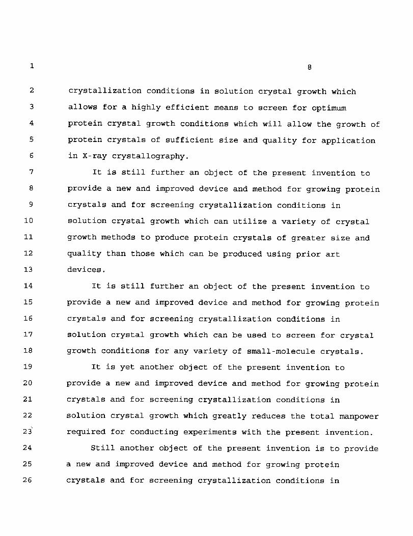
crystallization conditions in solution crystal growth which
allows for a highly efficient means to screen for optimum
protein crystal growth conditions which will allow the growth of
protein crystals of sufficient size and quality for application
in X-ray crystallography.
It is still further an object of the present invention to
provide a new and improved device and method for growing protein
crystals and for screening crystallization conditions in
solution crystal growth which can utilize a variety of crystal
growth methods to produce protein crystals of greater size and
quality than those which can be produced using prior art
devices.
It is still further an object of the present invention to
provide a new and improved device and method for growing protein
crystals and for screening crystallization conditions in
solution crystal growth which can be used to screen for crystal
growth conditions for any variety of small-molecule crystals.
It is yet another object of the present invention to
provide a new and improved device and method for growing protein
crystals and for screening crystallization conditions in
solution crystal growth which greatly reduces the total manpower
required for conducting experiments with the present invention.
Still another object of the present invention is to provide
a new and improved device and method for growing protein
crystals and for screening crystallization conditions in

9
2
3
4
5
6
7
8
9
i0
ii
12
13
14
15
16
17
18
19
20
21
22
23
24
25
26
solution crystal growth which will utilize a gelling substance
for limiting or controlling the rate of diffusive mixing of
crystallization solutions so that the solutions are diffusively
mixed over a predetermined period of time sufficient to achieve
equilibration and to substantially reduce density driven
convection disturbances therein.
A further object of the present invention is to provide a
new and improved device and method for growing protein crystals
and for screening crystallization conditions in solution crystal
growth which substantially eliminates and controls convective
flows associated with normal ig gravitational conditions thus
providing a diffusion limited process.
Another object of the present invention is to provide a new
and improved device and method for growing protein crystals and
for screening crystallization conditions in solution crystal
growth which eliminates numerous experiments to find the
appropriate experimental factors for optimum crystal growth thus
lending itself to automation.
Still a further object of the present invention is to
provide a new and improved device and method for growing protein
crystals and for screening crystallization conditions in
solution crystal growth which may be used for large scale
commercial crystallization screenings and crystal growth.
It is yet another object of the present invention to
provide a new and improved device and method for growing protein

1 i0
2
3
4
5
6
7
8
9
i0
ii
12
13
14
15
16
17
18
19
20
21
22
23
24
25
crystals and for screening crystallization conditions in
solution crystal growth which will substantially eliminate human
interaction to activate experiments which is especially helpful
in space missions.
Another object of the present invention is to provide a new
and improved device and method for growing protein crystals and
for screening crystallization conditions in solution crystal
growth that will indicate precise experimental factors for
growing larger and better quality crystals.
A further object of the present invention is to provide a
new and improved device and method for growing protein crystals
and for screening crystallization conditions in solution crystal
growth which allows for easy removal and access of crystals
without damage.
Still yet another object of the present invention is to
provide a new and improved device and method for growing protein
crystals and for screening crystallization conditions in
solution crystal growth which substantially decreases the amount
of expensive protein solution required for experiments.
Another object of the present invention is to provide a new
and improved device and method for growing protein crystals and
for screening crystallization conditions in solution crystal
growth which is easily mass produced and prepackaged, thus less
expensive to manufacture.

1
6
7
8
9
I0
Ii
12
13
14
15
16
17
18
19
20
21
22
23
24
25
26
Ii
A further object of the present invention is to provide a
new and improved device and method for growing protein crystals
and for screening crystallization conditions in solution crystal
growth which requires a much lower level of skill to perform
experiments.
These together with other objects of the present invention,
along with the various features of novelty which characterizes
the invention, are accomplished through the use of a device and
method for growing protein crystals and for screening
crystallization conditions in solution crystal growth which
comprises a housing having at least one pair chambers for
containing crystallization solutions. The chambers each have an
opening to the exterior of the housing. The housing further
includes a fluid communicating orifice connecting each pair of
chambers wherein the orifice is adapted to receive a detachable
tube which contains a predetermined quantity of gelling
substance for limiting and/or controlling the rate of diffusive
mixing of the crystallization solutions. When activated, the
solutions are diffusively mixed over a predetermined period of
time, defined by the quantity of gelling substance, sufficient
to achieve equilibration of the two crystallization solutions
and to substantially reduce density driven convection
disturbances therein.
The device further includes endcaps for sealingly closing
the openings of the two chambers. One of the endcaps includes a

1 12
2
3
4
5
6
7
8
9
I0
ii
12
13
14
15
16
17
18
19
20
21
22
23
24
25
26
dialysis chamber for containing a preselected quantity of
protein solution secured by a semipermeable membrane. In
another embodiment, the device may use glass coverslips instead
of endcaps when performing hanging drop vapor diffusion
experiments.
Limiting the rate of diffusive mixing of the two
crystallization solutions enables protein crystals to be grown
of sufficient size and quality to withstand crystal structural
analysis using x-ray diffraction techniques. In operation, the
protein solution is exposed to one of the crystallization
solutions wherein the solubility of the protein solution is
responsibly reduced at a rate substantially equal to the rate of
diffusive mixing of the two crystallization solutions through
the gelling substance. This rate controls the approach to
supersaturation of the protein solution and allows for quality
crystals to be grown. It also allows for screening of crystal
growth conditions at preselected intervals and substantially
reduces density driven convection within the protein solution.
There has thus been outlined, rather broadly, the more
important features of the present invention in order that the
detailed description thereof that follows may be better
understood, and that the present contribution to the art may
better appreciated. There are, of course, numerous other novel
features of the present invention that will become apparent from
a study of the drawings and the description of the preferred
13
2
3
4
5
6
7
8
9
I0
ii
12
13
14
15
16
17
18
19
20
21
22
23
24
25
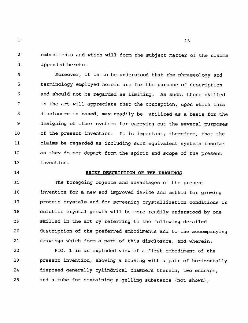
embodiments and which will form the subject matter of the claims
appended hereto.
Moreover, it is to be understood that the phraseology and
terminology employed herein are for the purpose of description
and should not be regarded as limiting. As such, those skilled
in the art will appreciate that the conception, upon which this
disclosure is based, may readily be utilized as a basis for the
designing of other systems for carrying out the several purposes
of the present invention. It is important, therefore, that the
claims be regarded as including such equivalent systems insofar
as they do not depart from the spirit and scope of the present
invention.
BRIEF DESCRIPTION OF THE DRAWINGS
The foregoing objects and advantages of the present
invention for a new and improved device and method for growing
protein crystals and for screening crystallization conditions in
solution crystal growth will be more readily understood by one
skilled in the art by referring to the following detailed
description of the preferred embodiments and to the accompanying
drawings which form a part of this disclosure, and wherein:
FIG. 1 is an exploded view of a first embodiment of the
present invention, showing a housing with a pair of horizontally
disposed generally cylindrical chambers therein, two endcaps,
and a tube for containing a gelling substance (not shown);
1 14
2
3
4
5
6
7
8
9
I0
ii
12
13
14
15
16
17
18
19
20
21
22
23
24
25
26
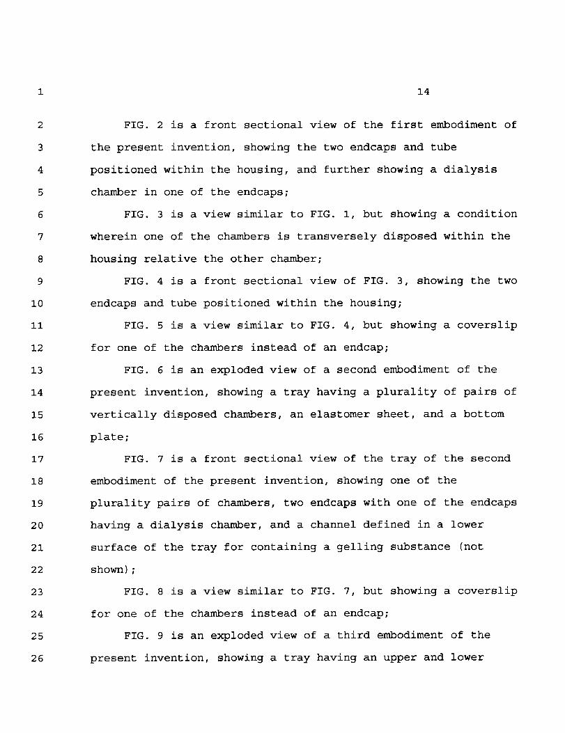
FIG. 2 is a front sectional view of the first embodiment of
the present invention, showing the two endcaps and tube
positioned within the housing, and further showing a dialysis
chamber in one of the endcaps;
FIG. 3 is a view similar to FIG. I, but showing a condition
wherein one of the chambers is transversely disposed within the
housing relative the other chamber;
FIG. 4 is a front sectional view of FIG. 3, showing the two
endcaps and tube positioned within the housing;
FIG. 5 is a view similar to FIG. 4, but showing a coverslip
for one of the chambers instead of an endcap;
FIG. 6 is an exploded view of a second embodiment of the
present invention, showing a tray having a plurality of pairs of
vertically disposed chambers, an elastomer sheet, and a bottom
plate;
FIG. 7 is a front sectional view of the tray of the second
embodiment of the present invention, showing one of the
plurality pairs of chambers, two endcaps with one of the endcaps
having a dialysis chamber, and a channel defined in a lower
surface of the tray for containing a gelling substance (not
shown);
FIG. 8 is a view similar to FIG. 7, but showing a coverslip
for one of the chambers instead of an endcap;
FIG. 9 is an exploded view of a third embodiment of the
present invention, showing a tray having an upper and lower

1 15
6
7
8
9
i0
II
12
13
14
15
16
17
18
19
20
21
22
23
24
25
surface, a plurality of vertically disposed chambers defined in
the tray, a layer of acrylic tape disposed on the upper surface
of the tray, a layer of acrylic tape disposed on the lower
surface of the tray, an elastomer sheet, and a bottom plate; and
FIG. 10 is a front sectional view of the tray of the third
embodiment of the present invention, showing one of the
plurality of pairs of vertically disposed chambers, a conically
shaped portion of one of the chambers, and a channel for
containing a gelling substance (not shown).
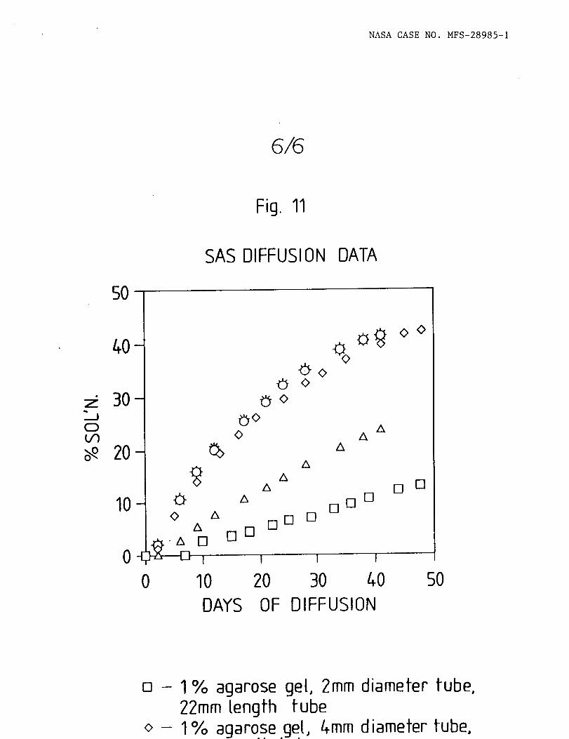
FIG. ii is a graphical representation of equilibration
profiles for identical solutions of saturated ammonium sulphate
diffusion rates as a function of tube length, tube inner
diameter, and type of gelling substance.
DETAILED DESCRIPTION OF THE PREFERRED EMBODIMENTS
Referring to the drawings for a clearer understanding of
the present invention, FIGS. 1-5 disclose a first embodiment of
the present invention which comprises a new and improved device
ii for determining optimum crystallization conditions in
solution crystal growth and for growing protein crystals of
sufficient size and quality to withstand crystal structural
analysis using x-ray diffraction techniques. The unique
construction of and methodologies employed by the device ii
allow for its utilization in either ig or extended microgravity
environments and will provide invaluable avenues to the
1 16
2
3
4
5
6
7
8
9
i0
II
12
13
14
15
16
17
18
19
20
21
22
23
24
25
26
understanding of detailed atomic structure and function of
biological macromolecules and other substances.
Referring to FIGS. 1 and 2, the device 11 may comprise a
cylindrical housing 12 having a pair of preferably cylindrical
first 13 and second 14 chambers defined therein for containing
crystallization (i.e., precursor, precipitant, buffers, etc.)
solutions (not shown), respectively. The chambers 13, 14 have
first 16 and second 17 openings to the exterior of the housing
12, respectively, for adding and subtracting the crystallization
solutions. Even though the housing 12 is preferably cylindrical
in shape, it may be rectangular, as shown in FIGS. 3-5, and
contain a plurality of pairs of chambers (not shown), preferably
up to six pairs, arranged side-by-side. This configuration is
most readily employed in commercial bulk crystallizations.
Moreover, the housing 12, as disclosed in FIGS. 1-5, has a
length of approximately 2.6 inches, and a diameter (height and
width) of approximately 1.5 inches. Again, it should be noted
that the housing 12 may be any size depending on the
circumstances such as in the case of large scale
crystallizations.
The device ii is preferably constructed of transparent
plastic such as polystyrene, polycarbonate, polysulphone or high
molecular weight polyethylene. Such material allows a user to
easily observe crystal growth or crystallization conditions at
preselected time intervals during an experiment. However, a
1 17
6
7
8
9
i0
ii
12
13
14
15
16
17
18
19
20
21
22
23
24
25
26
variety of other suitable materials could be utilized including
glass, as is readily obvious to one skilled in the art.
As noted above, the chambers 13, 14 are preferably
cylindrical in shape for ease of construction. Typically, the
first chamber 13 is sized to contain approximately 2ml of
crystallization solution and the second chamber 14 approximately
6ml, thus having a volume ratio of the first chamber 13 to the
second chamber 14 of approximately 1:3. Again, however, the
chambers 13, 14 may be considerably larger (i.e., may have any
volume ratio) such as in the case of commercial bulk
crystallizations.
As illustrated in FIGS. 1 and 2, the first 13 and second 14
chambers are both horizontally disposed and in co-axial
alignment within the housing 12. This configuration is
typically used in dialysis method experiments. Alternatively,
as shown in FIGS. 3-5, the first chamber 13 is transversely
disposed (i.e., vertically disposed) relative the second chamber
14 within the housing 12. This configuration is typically used
in vapor diffusion method experiments. In both cases or
configurations, however, the housing 12 further defines a first
annular ledge 18 within the first chamber 13 and a second
annular ledge 19 within the second chamber 14.
Furthermore, the housing 12 defines an orifice 21 between
the first 13 and second 14 chambers for providing a fluid
communication means therebetween. As shown in FIGS. 1 and 2,

1 18
2
3
4
5
6
7
8
9
I0
ii
12
13
14
15
16
17
18
19
20
21
22
23
24
25
26
the orifice 21 is co-axially aligned with both of the chambers
13, 14 and is adapted to detachably receive or threadingly
engage a hollow insert or tube 22. The function of the tube 22
is to contain a predetermined quantity of gelling substance (not
shown) which acts to limit the rate of diffusive mixing of the
first and second crystallization solutions so that the solutions
are diffusively mixed over a predetermined period of time
sufficient to achieve equilibration and to substantially reduce
density driven convection disturbances therein. The tube 22 may
be co-extensively positioned or received within the orifice 21
or may have a portion 24 extending a predetermined distance into
the second chamber 14 as shown in FIGS. 2, 4 and 5. Thus, the
orifice 21 is designed to engage a variety of interchangeable
differing diameter and length tubes 22 which will define the
quantity of gelling substance contained therein. For non-bulk
experiment specific crystallizations, the inner diameter of the
tube 22 is approximately 2-4mm and the length is approximately
ll-22mm.
Referring to FIGS. 1-4, the device 11 further includes
first 26 and second 27 endcaps detachably connected to the
housing 12 for closing the first 16 and second 17 openings,
respectively, of the first 13 and second 14 chambers.
Preferably, the endcaps 26, 27 will threadingly engage the
housing 12. Each endcap 26, 27 has an inner surface 28 and an
outer surface 29 wherein the inner surface 28 engages the first
19
2
3
4
5
6
7
8
9
I0
ii
12
13
14
15
16
17
18
19
20
21
22
23
24
25
26
18 and second 19 annular ledges, respectively, when the endcaps
26, 27 are connected to the housing 12. Moreover, each endcap
26, 27 includes an o-ring 31 for sealingly engaging the first 18
and second 19 annular ledges, respectively.
Alternatively, acrylic tape (not shown) could be used in
place of the endcaps 26, 27 such as when commercially available
dialysis buttons or bags are placed in the first chamber 13.
As noted earlier, the device ii may be utilized with both
dialysis and vapor diffusion method experiments. For dialysis
method experiments, as shown in FIGS. 1-4, the first endcap 26
will include a dialysis chamber 32 integrally connected at the
center of the inner surface 28 of the first endcap 26 for
containing a preselected quantity of protein solution (not
shown). The protein solution is contained within the dialysis
chamber 32 by use of a semipermeable membrane 33 which is held
in place by an o-ring 34. Once the first endcap 26 is connected
to the housing 12, the dialysis chamber 32 will be in
communication with the first chamber 13, thus exposed to the
crystallization solution therein. More specifically, the
dialysis chamber 32 will be submerged in the crystallization
solution within the first chamber 13.
In both dialysis and vapor diffusion method experiments,
the protein solution is exposed to the first crystallization
solution wherein the solubility of the protein solution is
reduced at a rate responsive or generally equal to the rate of

1 20
2
3
4
5
6
7
8
9
I0
ii
12
13
14
15
16
17
18
19
20
21
22
23
24
25
26
diffusive mixing of the first and second crystallization
solutions. This provides a controlled approach to
supersaturation of the crystallization solutions and provides an
opportunity to screen crystal growth conditions at preselected
intervals during the diffusive mixing. It also substantially
reduces density driven convection disturbances.
In addition, each endcap 26, 27 defines a pair of pin holes
36 symetrically disposed around the center of the outer surface
29 of the endcaps 26, 27 for mating with a tool to aid in the
tightening and removing of the endcaps 26, 27 and for not
obstructing a clear viewing of the dialysis chamber 32.
Moreover, each endcap 26, 27 defines a vent hole 37 therethrough
which is in communication with the first 13 and second 14
chambers. The vent hole 37 includes a standard bolt 38 and
o-ring 39 for selectively venting pressure build-up within the
chambers 13, 14 during engagement of the endcaps 26, 27.
Referring to FIG. 5, a glass coverslip 23 may be used in
place of the first endcap 26. The coverslip 23 is most readily
used in "hanging-drop" vapor diffusion method experiments.
Acrylic tape (not shown) is used to secure the coverslip 23 to
the housing 12. This orientation provides a more convenient
means to observe changes via microscopic examination in the
protein solution. When the hanging drop method is employed,
fluid levels are adjusted to be of equal height in the first 13
and second 14 chambers so that no hydrostatic pressure

1 21
2
3
4
5
6
7
8
9
I0
ii
12
13
14
15
16
17
18
19
20
21
22
23
24
25
26
difference is generated and so that an appropriate volume of
vapor phase exists between the protein droplet and the
crystallization solution.
In operation, crystal growth and crystallization screens
are conducted in the following manner. A suitable gelling
substance (not shown) such as polyacrylamide, gelatin, agarose,
or silica gel is injected by syringe into the tube 22 and
allowed to gel, whereupon the tube 22 is threaded into the
orifice 21 inside of the housing 12. A portion of the tube 22
extends a predetermined distance into the second chamber 14 in
order to keep the convective disturbances associated with the
diffusive mixing of the crystallization solutions away from the
protein solution. Once a suitable period has passed for gelling
to occur, a concentrated solution of precipitant is added to the
second chamber 14 (the precipitant reservior) and sealed with
the second endcap 27. Next, the protein solution is placed in
the dialysis chamber 32 and secured with the semipermeable
membrane 33 and o-ring 34 or placed on the coverslip 23. Once
the protein solution is secured, the first chamber 13 is filled
with an appropriate dilute solution of precipitant agent and
buffer. When the first chamber 13 is sealed with the first
endcap 26 or coverslip 23, the crystallization solutions are in
fluid communication with one another. At this time, the
experiment has been activated and will progress until the two
solutions come to equilibrium.

1
2
3
4
5
6
7
8
9
i0
ii
12
13
14
15
16
17
18
19
20
21
22
23
24
25
26
22
The length of time to reach equilibrium depends on the size
or volume of the communication between the first 13 and second
14 chambers (i.e., primarily the length and diameter of the tube
22 which defines the amount of gelling substance), the volumes
of the first 13 and second 14 chambers, as well as, temperature,
concentrations between the two crystallization solutions, and
other factors. Known classical mathematical formula derived to
explain diffusive phenomena are used to calculate the
equilibrium times and profiles taking into account these
variables.
For example, FIG. ii shows diffusion profiles for identical
solutions of saturated ammonium sulphate (SAS) and water through
varying concentrations of agarose gel. The water is contained
in the first chamber 13 and the ammonium sulphate in the second
chamber 14. All five of the diffusion profiles shown were
conducted at room temperature. Under typical conditions, the
experiments require approximately 3-6 months to reach
equilibrium.
As indicated by a "square" in FIG. ii, a tube 22 having an
inner diameter of approximately 2mm and a length of
approximately 22mm which is filled with 1% agarose gel will
define a diffusion rate of approximately 1.7% saturated sulphate
per week. This means that the concentration of the ammonium
sulphate in the water contained in the first chamber 13 will
rise at a rate of approximately 1.7% per week until the

1
6
7
8
9
I0
ii
12
13
14
15
16
17
18
19
20
21
22
23
24
25
26
23
experiment approaches equilibrium. When the appropriate
conditions of supersaturation are met, crystals are induced to
form.
As indicated by a "diamond" in FIG. ii, a tube 22 having an
inner diameter of approximately 4mm and a length of
approximately llmm, which is filled with 1% agarose gel, will
define a diffusion rate of approximately 4% saturated sulphate
per week. This means that the concentration of the ammonium
sulphate in the water contained in the first chamber 13 will
rise at a rate of approximately 4% per week until the experiment
approaches equilibrium.
As indicated by a "circle" in FIG. ii, a tube 22 having an
inner diameter of approximately 4mmand a length of
approximately llmm, which is filled with 0.6% agarose gel, will
define a diffusion rate of approximately 10% per week. This
means that the concentration of the ammonium sulphate in the
water contained in the first chamber 13 will rise at a rate of
approximately 10% per week until the experiment approaches
equilibrium.
As indicated by a "triangle" in FIG. ii, a tube 22 having
an inner diameter of approximately 4mm and a length of
approximately 22mm, which is filled with 0.6% agarose gel, will
define a diffusion rate of approximately 10% per week. This
means that the concentration of the ammonium sulphate in the
water contained in the first chamber 13 will rise at a rate of

1
2
3
4
5
6
7
8
9
i0
Ii
12
13
14
15
16
17
18
19
20
21
22
23
24
25
26
24
approximately 10% per week until the experiment approaches
equilibrium.
As indicated by a "asterisk" in FIG. ii, a tube 22 having
an inner diameter of approximately 4mm and a length of
approximately 22mm, which is filled with 0.3% agarose gel, will
define a diffusion rate of approximately 10% per week. This
means that the concentration of the ammonium sulphate in the
water contained in the first chamber 13 will rise at a rate of
approximately 10% per week until the experiment approaches
equilibrium.
This method, whether dialysis or vapor diffusion, requires
the preparation in advance of concentrated stock solutions.
Most importantly, however, it does not require the tedious
preparation of individual experiments at increments in 5% steps
of each of the precipitant concentrations (i.e., conditions).
Thus, each experiment using the present invention takes the
place of approximately 12 prior art crystallization screens.
For instance, a typical crystallization screen using prior art
devices and methods of five different precipitating agents would
consist of approximately 480 individual experiments, regardless
of whether they are dialysis or vapor diffusion experiments. In
contrast, the same experiment using the present invention would
create only 40 experiments and require a much lower skill level
to prepare, thus resulting in a considerable savings in time and
valuable protein solution.

25
2
3
4
5
6
7
8
9
i0
ii
12
13
14
15
16
17
18
19
20
21
22
23
24
25
26
The experiments are monitored visually on intervals of
approximately once a week in order that the proper conditions
for crystal growth can be identified. This information may be
ascertained in two simple ways: (i) by directly measuring the
refractive index of the solution in the first chamber 13; or (2)
by noting precisely when crystal growth occurred, such as by
automated processes which can be monitored by robotics followed
by subsequent calculations of the concentration. Generally,
such a slow approach to supersaturation has other advantages as
well as that it produces fewer and larger protein crystals of
higher quality and that the present invention possesses no
moving fluids.
A second embodiment of the present invention is illustrated
in FIGS. 6-8 which comprises an apparatus 41 for determining
optimum protein crystal growth conditions and for growing
protein crystals in either ig or microgravity environments. The
apparatus 41 comprises a preferably rectangular tray 42 having
an upper 43 and lower 44 surface. The tray 42 defines at least
one pair of first 46 and second 47 vertically disposed chambers
therein for containing first and second crystallization
solutions, respectively. The chambers 46, 47 are the same size
and shape as that described in the first embodiment.
Preferably, the tray 42 will include six pairs of chambers 46,
47. The chambers 46, 47 have first 48 and second 49 openings
through the upper surface 43 to the exterior of the tray 42,

1 26
2
3
4
5
6
7
8
9
I0
Ii
12
13
14
15
16
17
18
19
20
21
22
23
24
25
26
respectively, and first 51 and second 52 orifices through the
lower surface 44 to the exterior of the tray 42, respectively.
As shown in FIGS. 7 and 8, the tray 42 further defines a
channel 53 in its lower surface 44 which provides continuous
fluid communication between the first 51 and second 52
orifices. The channel 53 is adapted to contain a predetermined
quantity of gelling substance (not shown) which acts to limit
the rate of diffusive mixing of the first and second
crystallization solutions wherein the solutions are diffusively
mixed over a predetermined period of time defined by the
quantity of gelling substance sufficient to achieve
equilibration and to substantially reduce density driven
convection disturbances therein. Preferably, the channel 53 has
a length of approximately ll-22mm and a width and depth of
approximately 2-4mm.
The apparatus 41 further comprises first 54 and second 56
endcaps detachably connected to the tray 42 for closing the
first 48 and second 49 openings, respectively, and are
substantially identical to those described in the first
embodiment. The first endcap 54 includes a dialysis chamber 57
integrally formed thereto for containing a preselected quantity
of protein solution (not shown) in which protein crystals are
grown of sufficient size and quality to withstand crystal
structural analysis using x-ray diffraction techniques. The
protein solution is exposed to the first crystallization
1 27
2
3
4
5
6
7
8
9
i0
ii
12
13
14
15
16
17
18
19
20
21
22
23
24
25
26
solution in the first chamber 46 wherein the solubility of the
protein solution is reduced at a rate responsive to the rate of
diffusive mixing of the first and second crystallization
solutions thus providing a controlled approach to critical
supersaturation. This controlled approach allows for screening
of crystal growth conditions at preselected intervals during the
time of diffusive mixing of the crystallization solutions.
Moreover, the controlled approach to supersaturation
substantially reduces density driven convection within the
protein solution.
As illustrated in FIGS. 6-8, the apparatus 41 further
comprises a bottom plate 58 attached to the lower surface 44 of
the tray 42 and an elastomer sheet 59 attached intermediate the
tray 42 and the bottom plate 58 for sealingly engaging the
channel 53 and the first 51 and second 52 orifices. Moreover,
the bottom plate 58 and the elastomer sheet 59 are preferably
coextensive with the tray 42 (i.e., the same length and width)
and connected thereto with machine screws 60 or any other known
method.
Again, the first 46 and second 47 chambers are the same
shape and volume as those disclosed in the first embodiment of
the present invention. Likewise, the tray 42 further defines a
first 61 and second 62 annular ledge within the first 46 and
second 47 chambers, respectively, proximal the upper surface
43. Each endcap 54, 56 has an inner surface 63 and an outer

28
2
3
4
5
6
7
8
9
i0
ii
12
13
14
15
16
17
18
19
20
21
22
23
24
25
26
surface 64 wherein the inner surface 63 engages the first 61 and
second 62 annular ledges, respectively, when the endcaps 54, 56
are connected (preferably threaded) to the tray 42. Moreover,
each endcap 54, 56 includes an o-ring 66 for sealingly engaging
the first 61 and second 62 annular ledges, respectively. As
mentioned in the first embodiment, acrylic tape (not shown)
could be used in place of the endcaps 54, 56 when commercially
available dialysis buttons or bags are placed in the first
chamber 46.
Referring to FIG. 8, a glass coverslip 65 may be used in
place of the first endcap B4. The coverslip 65 is most readily
used in "hanging drop" vapor diffusion method experiments.
Acrylic tape (not shown) is used to secure the coverslip 65 to
the tray 42.
The method of operation of the second embodiment is a
combination of the methods described in the first and third
embodiments, thus are incorporated here for convenience.
Likewise, the materials used for the elements in the second
embodiment are the same as those disclosed in the first
embodiment.
A third embodiment of the present invention is shown in
FIGS. 9 and i0 which comprises a disposable device 67 for
growing easily accessable protein crystals of sufficient size
and quality to withstand crystal structural analysis using X-ray
diffraction techniques. The device 67 comprises a tray 68

1 29
6
7
8
9
i0
ii
12
13
14
15
16
17
18
19
20
21
22
23
24
25
26
having an upper 69 and lower 71 surface. The tray 68 defines at
least one pair of first 72 and second 73 vertically disposed
chambers therein for containing a protein solution (not shown)
and a precipitant solution (not shown), respectively. As in the
second embodiment, the tray 68 will preferably include six pairs
of chambers 72, 73, the first chamber 72 however containing
approximately ten microliters of protein solution, and the
second chamber 73 approximately 500 microliters. Moreover, the
tray 68 will have a preferable length of approximately four
inches, a width of approximately six inches, and a height of
approximately 1/2 inch.
The chambers 72, 73 further have first 74 and second 76
openings through the upper surface 69 of the tray 68,
respectively, and a first restricted orifice 77 and a second
orifice 78 through the lower surface 71 of the tray 68,
respectively. In addition, the first chamber 72 further defines
a conically shaped portion 79 adjacent or proximal to the first
restricted orifice 77. The first restricted orifice 77 provides
a pressure seal for a syringe (not shown) during injection of a
gelling substance, which is described in more detail below.
As shown in FIG. 10, the tray 68 further defines a channel
81 in its lower surface 71 which provides continuous fluid
communication between the first 77 and second 78 orifices. The
channel 81 is adapted to contain a predetermined quanity of
gelling substance (not shown) which limits the rate of diffusive
30
2
3
4
5
6
7
8
9
I0
II
12
13
14
15
16
17
18
19
20
21
22
23
24
25
mixing of the protein solution and the precipitant solution
wherein the solutions are diffusively mixed over a predetermined
period of time defined by the quanity of the gelling substance.
It is preferable that the width and depth of the channel 81 be
approximately 4mm and 2mm, respectively. The time it takes to
diffusively mix the solutions should be sufficient to
controllably reduce the solubility of the protein solution
within the gelling substance to the point of critical
supersaturation whereby crystals are induced to grow in the
gelling substance within the channel 81.
The device 67 further comprises two layers of clear
synthetic plastic tape 82, which can be either polyester or
polypropylene, connected to the upper 69 and lower 71 surface of
the tray 68 for sealingly engaging the first 74 and second 76
openings and the first 77 and second 78 orifices and channel 81,
respectively. The types of tape 82 mentioned above are
generally preferred because of their superior sealing and
thermal properties and, in addition, employ as an adhesive a
compound (acroolefin) which is a safe biocompatible material.
Moreover, the device 67 further comprises a bottom plate 83
detachably connected to the lower surface 71 of the tray 68 and
an elastomer sheet 84 detachably connected to the lower surface
71 of the tray 68 intermediate the tape 82 on the lower surface
71 and the bottom plate 83.

1 31
7
8
9
I0
II
12
13
14
15
16
17
18
19
20
21
22
23
24
25
Preferably, the layers of plastic tape 82, the elastomer
sheet 84, and the bottom plate 83, are all coextensive with the
tray 68 (i.e., the same rectangular size). In addition, the
tray 68 should be constructed out of polystyrene, polycarbonate,
polysulphone or high molecular weight polyethylene.
Preferably, the typical operation of the third embodiment
would be performed as follows. First, a layer of plastic tape
82 would be attached to the lower surface 71 of the tray 68 to
seal the bottom of the tray 68. Then the elastomer sheet 84 and
the bottom plate 83 would be connected to the lower surface 71
of the tray 68 covering the plastic tape 82. The elastomer
sheet 84 and the bottom plate 83 may either be connected and
tightened with machine screws 86 or placed in mechanical press
(not shown) suitable for automation purposes so as to compress
the elastomer sheet 84 to form an effective seal. The gelling
substance (not shown) is then injected by syringe into the
channel 81 and allowed to gel.
After gelling has occurred, the device 67 is disassembled
leaving the tray 68 with the gelling substance and plastic tape
82 intact. Protein and precipitant solutions (not shown) are
then added to the first 72 and second 73 chambers, respectively.
Another layer of plastic tape 82 is attached to the upper
surface 69 of the tray 68 to seal the upper surface 69. At this
time, the experiment has been activated.

1 32
2
3
4
5
6
7
8
9
I0
ii
12
13
14
15
16
17
18
19
20
21
22
23
24
25
26
Crystals which grow in the gelling substance in the channel
81 are conveniently removed by cutting through the plastic tape
82 and prepared by known methods for X-ray diffraction studies.
The diffusive mixing of the protein and precipitant
solutions through a gelling substance described in the above
method is accomplished over a period of time defined by the
quantity of gelling substance. In light of the dimensions of
the channel 81 set out above, which dictate the quantity of
gelling substance, the period of time is sufficient to
controllably reduce the solubility of the protein solution to
the point of supersaturation whereby protein crystals are grown
having superior size and quality.
Thus, the device 67 provides a means to produce preprepared
disposable gel crystallization trays 68 which can be created
inexpensively and which provide a variety of gel options as well
as a more convenient method to conduct, store, monitor, and
document gel protein crystal growth experiments.
In light of the disclosure of the present invention as set
forth above, it is clear that numerous other objects and
features of the present invention that are inherent in the
disclosure will be readily appreciated by those skilled in the
art. For instance, any of the above mentioned embodiments can
be easily adapted for utilization in producing crystals in the
environment of an orbiting spacecraft having the advantage that
the experiments, when prepared prior to launch, do not require
1 33
2
3
4
5
6
7
human intervention to activate. In addition, it will be well
recognized to one skilled in the art that numerous changes and
modifications not specifically set forth can be made with regard
to the embodiments described above without departing from the
scope of the invention which is defined in the claims appended
hereto.

6
7
8
9
i0
ii
12
13
14
15
16
17
18
19
20
21
22
23
24
25
ABSTRACT OF THE DISCLOSURE
A device and method for detecting optimum protein
crystallization conditions and for growing protein crystals in
either ig or microgravity environments comprising a housing
defining at least one pair of chambers for containing
crystallization solutions. The housing further defines an
orifice therein for providing fluid communication between the
chambers. The orifice is adapted to receive a tube which
contains a gelling substance for limiting the rate of diffusive
mixing of the crystallization solutions. The solutions are
diffusively mixed over a period of time defined by the quantity
of gelling substance sufficient to achieve equilibration and to
substantially reduce density driven convection disturbances
therein.
The device further includes endcaps to seal the first and
second chambers. One of the endcaps includes a dialysis chamber
which contains protein solution in which protein crystals are
grown. Once the endcaps are in place, the protein solution is
exposed to the crystallization solutions wherein the solubility
of the protein solution is reduced at a rate responsive to the
rate of diffusive mixing of the crystallization solutions. This
allows for a controlled approach to supersaturation and allows
for screening of crystal growth conditions at preselected
intervals.

NASA CASE NO. MFS-28985-I
38
28
Fig.I
13 "-.
17
22 24
1231 36
79
27
12 31 13
/2
1111_+31
/ ,'//,',_ ' 36

NASA CASE NO. MFS-28985-I
12 Fig. 3
11/ 21
11
k 36 18\
31
2629 39 38
" 36"" 37
3627
36 12 1/+ 31
I _L./..t, I q8

NASA CASE NO. MFS-28985-I
/+I <
/

NASA CASE NO. MFS-28985-I
61
51 53 52 58 44
Fig. 7
61., 65
-62
)42.9

NASA CASE NO. MFS-28985-I
Fig.9
69
68
71 72l 76
82
72
"-73
82
67
83
67.,_, 6t9 714__lll" II___-_RIlIIIi-Ili
76!
NASA CASE NO. MFS-28985-I
Fig. 11
SAS DIFFUSION DATA
50
:JCD
o",9.
OO<>
<>
Ao A
A
AA
?OO
A
gg°I
10
DD D
DD DD
DAYS
<>0
I I I
20 30 40
OF DIFFUSION
50
] __ 1% agarose gel, 2mm diameter tube,22mm length tube1% agaros.e.ge.l, 4ramdiameter tube,