Embed Size (px)
Citation preview
MSC 04998
NATIONAL AERONAUTICS AND SPACE ADMINISTRATION
LUNAR SURFACE EXPERIMENTS
DEPLOYMENT CRITERIA
MISSION J-2/APOLLO 16
MANNED SPACECRAFT CENTER HOUSTON,TEXAS
October 15, 1971
LUNAR SURFACE EXPERIMENTS DEPLOYMENT CRITERIA
MISSION J-2/APOLLO 16
Prepared for the
Science Missions Support Division Science and Applications Directorate
and
Lunar Surface Project Office Engineering and Development Directorate
Manned Spacecraft Center Houston, Texas
MSC 04998
Approved by~.!7 ~~Af1 J: ·~~~~~~ ~~~~
Donald G. Wiseman, Manager Support Lunar Surface Project
Office
Comments related to this document should be forwarded to Mr. Glenn P. Barnes, Science Requirements and Operations Branch (TD5), telephone extension 5028; or Mr. Jackson D. Harris, Lunar Surface Project Office (EH4), telephone extension 2094.
ii
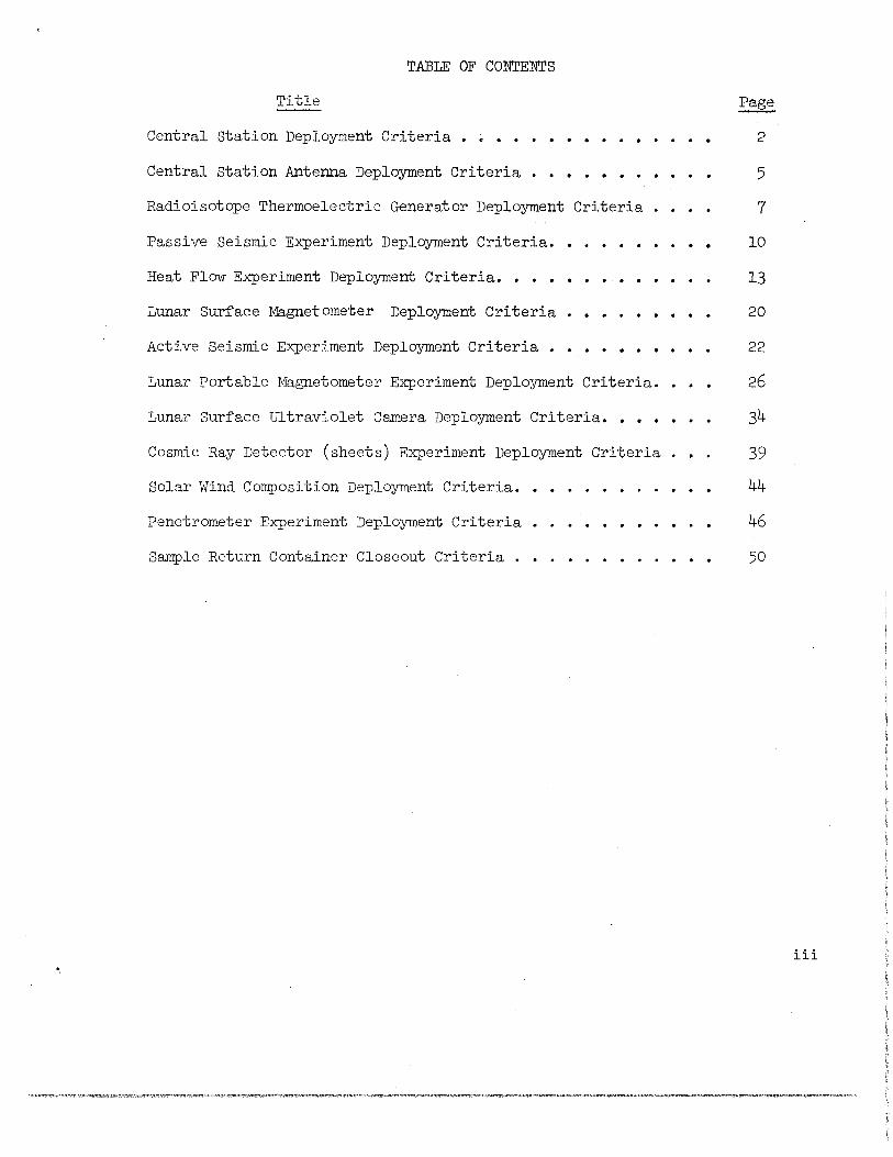
TABLE OF CONTENTS
Title
Central Station Deployment Criteria • ~ ••• . . . Central Station Antenna Deployment Criteria •
Radioisotope Thermoelectric Generator Deployment Criteria ••
Passive Seismic Experiment Deployment Criteria.
Heat Flow Experiment Deployment Criteria •••• . . Lunar Surface Magnetometer Deployment Criteria •
Active Seismic Experiment Deployment Criteria •
Lunar Portable Magnetometer Experiment Deployment Criteria.
Lunar Surface Ultraviolet Camera Deployment Criteria •••••
Cosmic Ray Detector (sheets) Experiment Deployment Criteria
Solar Wind Composition Deployment Criteria.
Penetrometer Experiment Deployment Criteria
Sample Return Container Closeout Criteria .
2
5
7
10
13
20
22
26
34
39
44
46
50
iii
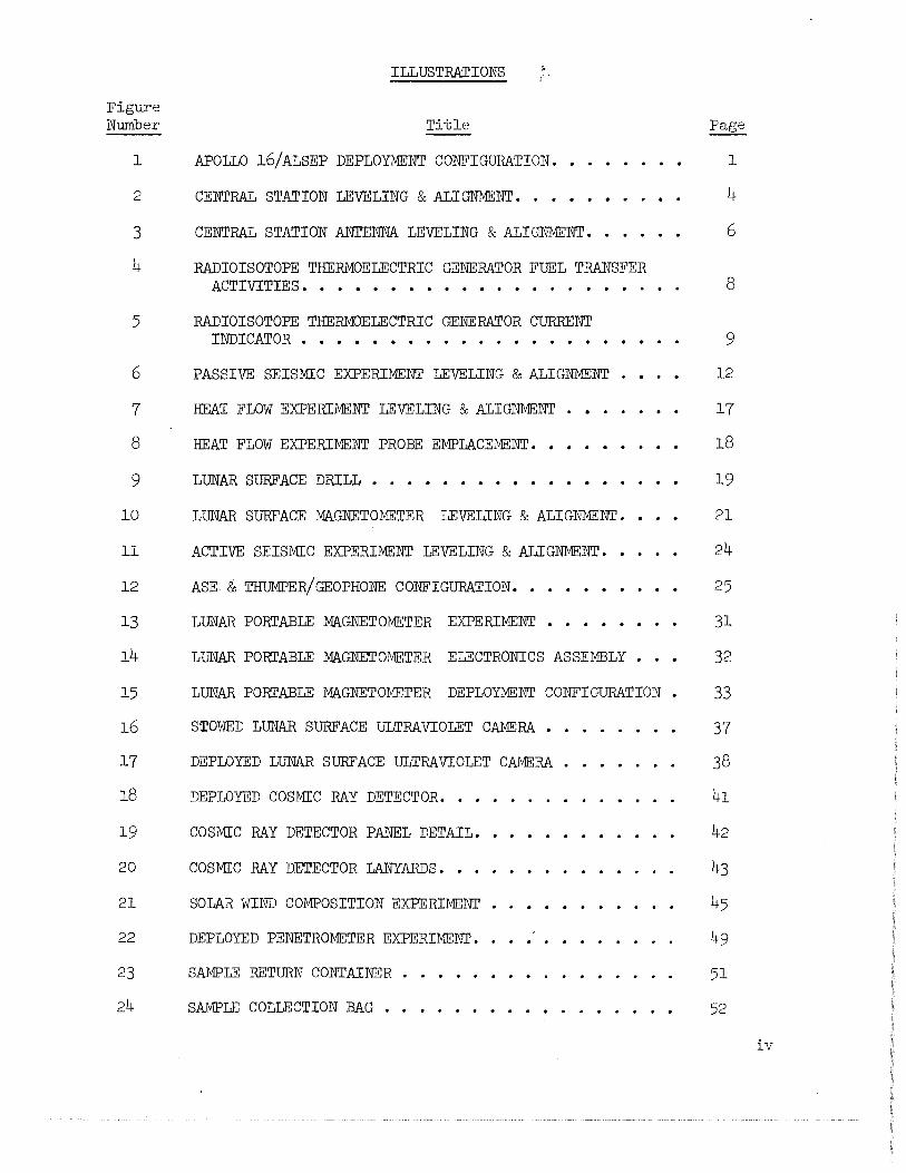
Figure Number
ILLUSTRATIONS
Title
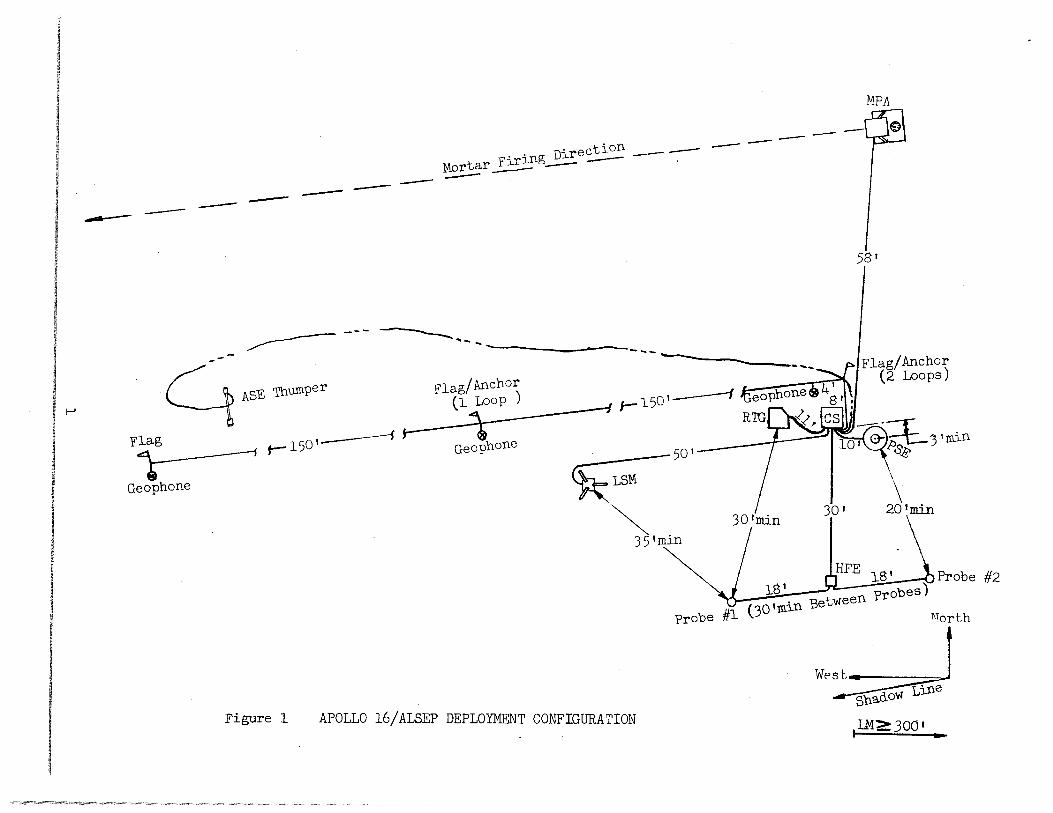
1 APOLLO 16/ALSEP DEPLOYMENT CONFIGURATION.
2 CENTRAL STATION LEVELING & ALIGNMENT ••••
3 CENTRAL STATION ANTENNA LEVELING & ALIGNMENT ••
4 RADIOISOTOPE THERMOELECTRIC GENERATOR FUEL TRANSFER ACTIVITIES • • • • • • • • • • • . • • . . •
5 RADIOISOTOPE THERMOELECTRIC GENERATOR CURRENT INDICATOR • • • • • • • . • . . . • • • • • •
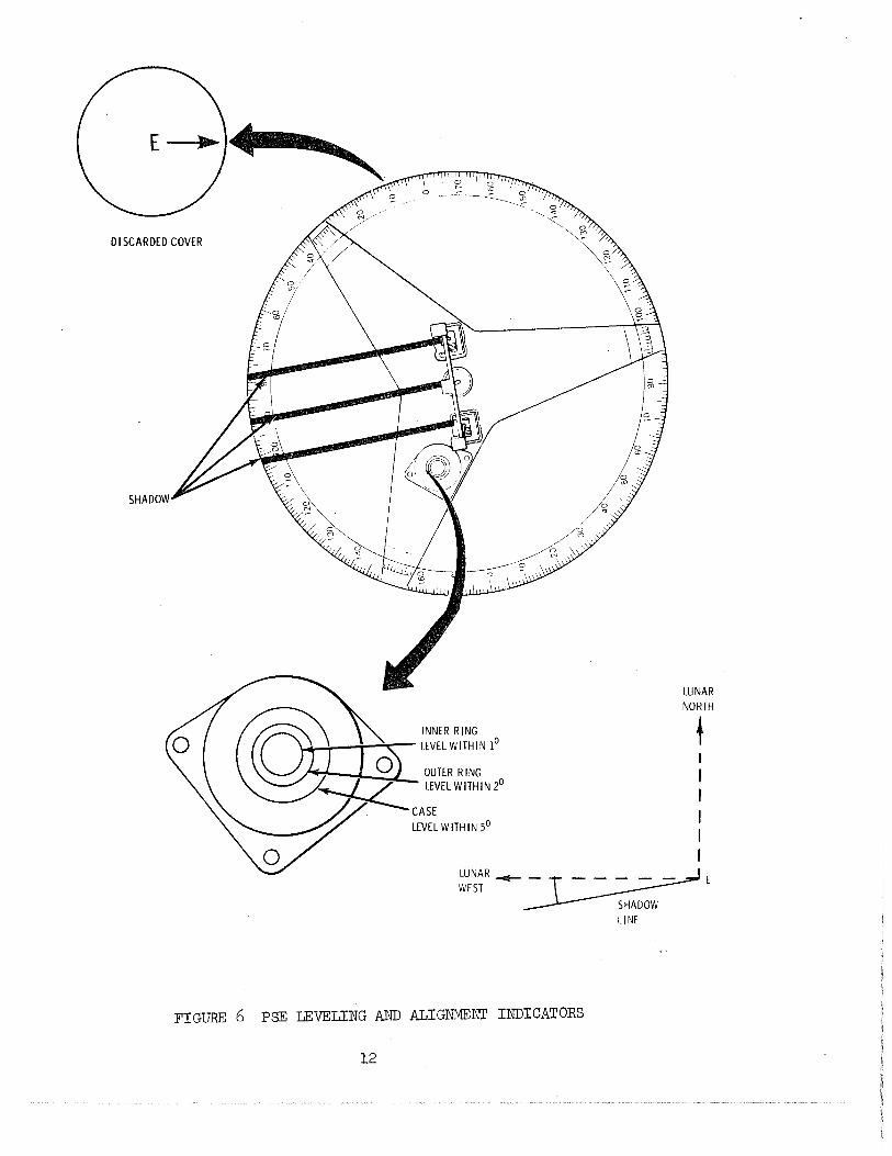
6 PASSIVE SEISMIC EXPERIMENT LEVELING & ALIGNMENT .
7 HEAT FLOW EXPERIMENT LEVELING & ALIGNMENT .
8 HEAT FLOW EXPERIMENT PROBE EMPLACEMENT.
9 LUNAR SURFACE DRILL • • • •
10 LUNAR SURFACE MAGNETOMETER LEVELING & ALIGNMENT.
11 ACTIVE SEISMIC EXPERIMENT LEVELING & ALIGNMENT.
12 ASE & THUMPER/GEOPHONE CONFIGURATION •••
13 LUNAR PORTABLE MAGNETOMETER EXPERIMENT
14 LUNAR PORI'ABLE MAGNETOMETER ELECTRONICS ASSEMBLY .
15 LUNAR PORI'ABLE MAGNETOMETER DEPLOYMENT CONFIGURATION •
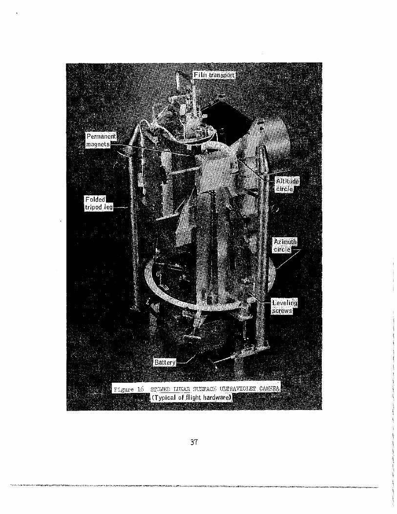
16 STOWED LUNAR SURFACE ULTRAVIOLET CAMERA •.
17 DEPLOYED LUNAR SURF ACE ULTRA VIOLET CAMERA .
18 DEPLOYED COSMIC RAY DETECTOR. . . •
19 COSMIC RAY DETECTOR PANEL DETAIL.
20 COSMIC RAY DETECTOR LANYARDS .•.
21 SOLAR WIND COMPOSITION EXPERIMENT • •
22 DEPLOYED PENETROMETER EXPERIMENT.
23 SAMPLE RETURN CONTAINER .
24 SAMPLE COLLECTION BAG . .
Page
1
4
6
8
9
12
17
18
19
21
24
25
31
32
33
37
38
41
42
43
45
49
51
52
iv
PARAMETER
Site Selection
Leveling
Alignment
Thermal Control
Photographic Requirements
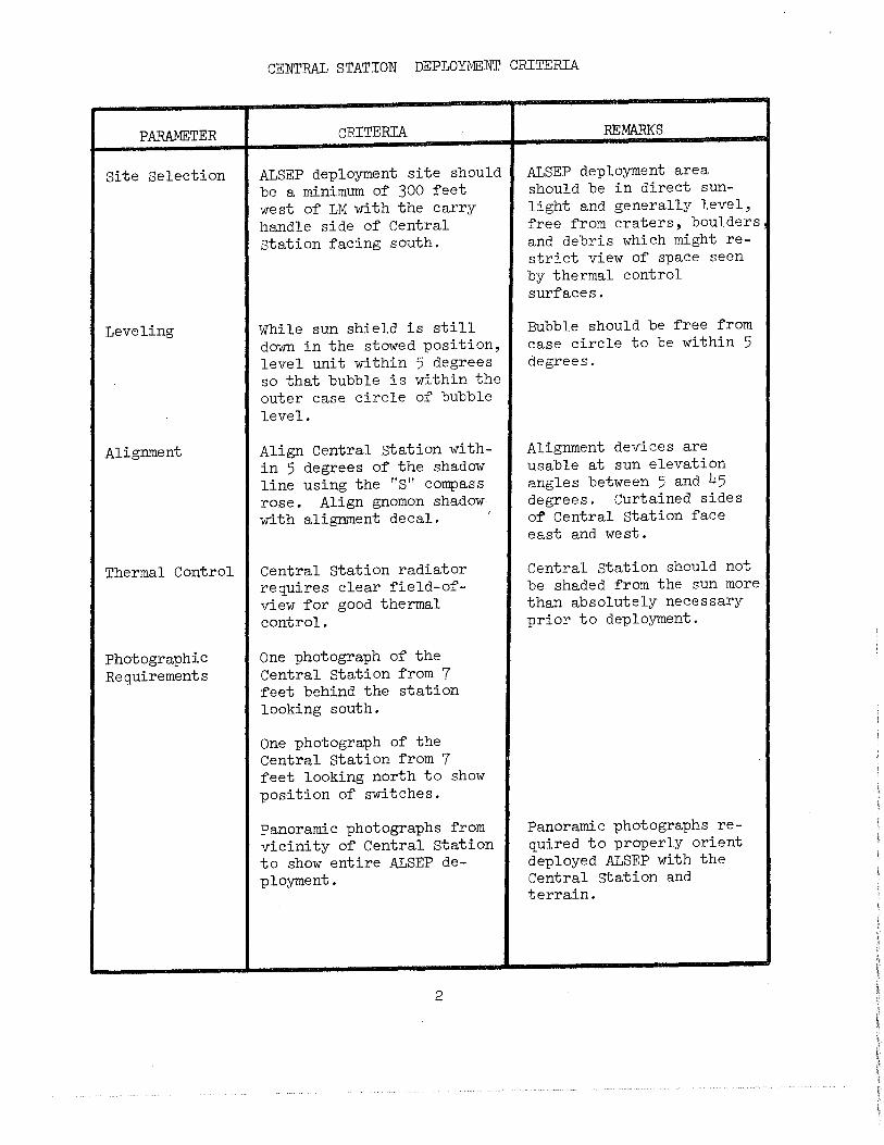
CENTRAL STATION DEPLOYME:NT CRITERIA
CRITERIA
ALSEP deployment site should be a minimum of 300 feet west of LM with the carry handle side of Central station facing south.
While sun shield is still down in the stowed position, level unit within 5 degrees so that bubble is within the outer case circle of bubble level.
Align Central Station within 5 degrees of the shadow line using the "S" compass rose. Align gnomon shadow with alignment decal. '
Central Station radiator requires clear field-ofview for good thermal control.
One photograph of the Central Station from 7 feet behind the station looking south.
One photograph of the Central Station from 7 feet looking north to show position of switches.
Panoramic photographs from vicinity of Central Station to show entire ALSEP deployment.
2
REMARKS
ALSEP deployment area should be in direct sunlight and generally level, free from craters, boulders and debris which might restrict view of space seen by thermal control surfaces.
Bubble should be free from case circle to be within 5 degrees.
Alignment devices are usable at sun elevation angles between 5 and 45 degrees. Curtained sides of Central Station face east and west.
Central station should not be shaded from the sun more than absolutely necessary prior to deployment.
Panoramic photographs required to properly orient deployed ALSEP with the Central station and terrain.
PARAMETER
Precautions
CENTRAL STATION DEPLOYMENT CRITERIA (Continued)
CRITERIA REMARKS
After the RTG has been connected to the Central Station by way of shorting plug switch, this plug should not be disconnected. If the circuit is broken, an un:-wanted irrevocable switching function will occur.
After Central Station deployment, do not bump or twist sunshield because of possible Hunter Spring damage.
3
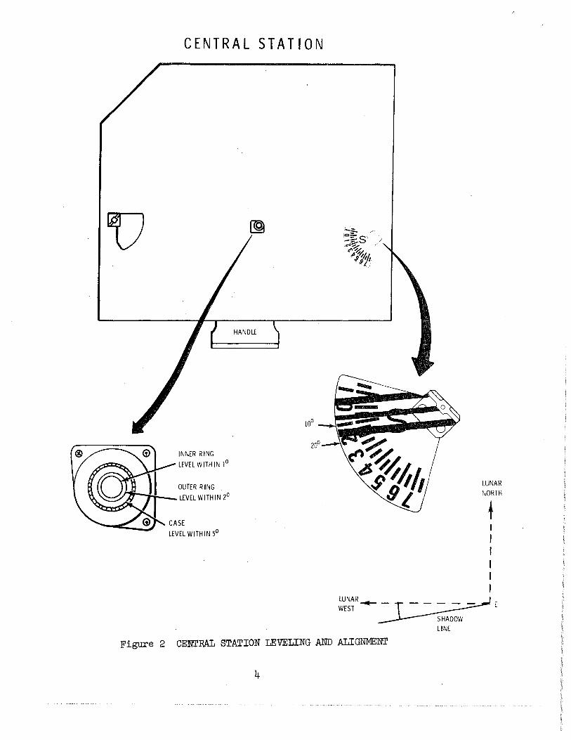
CENTRAL STATION
INNER R lNG
LEVEL WITHIN 1°
OUTER R lNG .,.--.....:........_ LEVEL WITHIN 2°
LEVEL WITHIN 5°
LUNAR NORTH
t I I I I I I
LUNAR~~E WEST
SHADOW LINE
Figure 2 CENTRAL STATION LEVELING AND ALIGNMENT
4
PARAMETER
Antenna Deployment
Antenna Level
Antenna Alignment
Antenna Azimuth
Antenna Elevation
Precautions
CENTRAL STATION ANTENNA DEPLOYMENT CRITERIA
CRITERIA
With the antenna mechanism still in unit stowage container, position the antenna aiming mechanism on the mast with the arrow pointed toward the sun.
Level antenna within 0.5 degrees of vertical as indicated by bubble level.
Align antenna within 0.5 degrees of sun line as determined by sun dial.
Set azimuth dial to value sho~~ on cuff check list to assure adequate signal strength for life of ALSEP.
Set elevation dial to value shown on cuff check list to assure adequate signal strength for life of ALSEP.
REMARKS
This will ensure that the alignment shadowgraph is on the east side of the mechanism.
Bubble should be free from case circle to be level within 0.5 degrees.
When shadow covers shadow reference block, antenna is aligned within 0.5 degrees.
For sun angle of (TBD) degrees set azimuth CCW to:
Coarse Scale: TBD
For sun angle of (TBD) degrees set elevation CCW to:
Coarse Scale: TBD
Verify visually that antenna is properly seated into Central Station fixture and generally pointed toward earth.
5
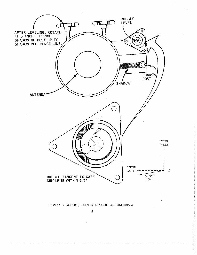
AFTER LEVELING, ROTATE THIS KNOB TO BRING SHADOW OF POST UP TO SHADOW REFERENCE LINE.
BUBBLE TANGENT TO CASE CIRCLE IS WITHIN 1/2°
BUBBLE LEVEL
Figure 3 CENTRAL STATION LEVELING AND ALIGNMENT
6
L~ NORTH
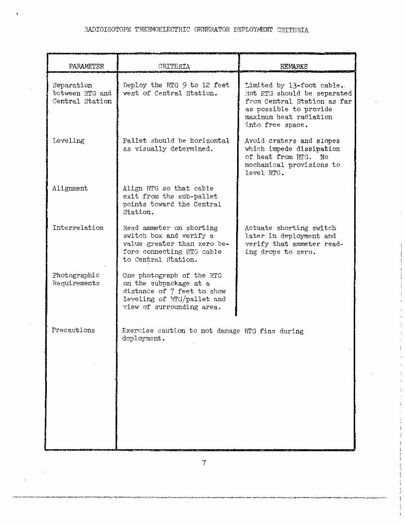
RADIOISOTOPE THERMOELECTRIC GENERATOR DEPLOYMENT CRITERIA
PARAMETER
Separation between RTG and Central Station
Leveling
Alignment
Interrelation
Photographic Requirements
Precautions
CRITERIA
Deploy the RTG 9 to 12 feet west of Central station.
Pallet should be horizontal as visually determined.
Align RTG so that cable exit from the sub-pallet points toward the Central Station.
Read ammeter on shorting switch box and verify a value greater than zero before connecting RTG cable to Central Station.
One photograph of the RTG on the subpackage at a distance of 7 feet to show leveling of RTG/pallet and view of surrounding area.
REMARKS
Limited by 13-foot cable., Hot RTG should be separated from Central Station as far as possible to provide maximum heat radiation into free space.
Avoid craters and slopes which impede dissipation of heat from RTG. No mechanical provisions to level RTG.
Actuate shorting switch later in deployment and verify that ammeter reading drops to zero.
Exercise caution to not damage RTG fins during deployment.
7
co
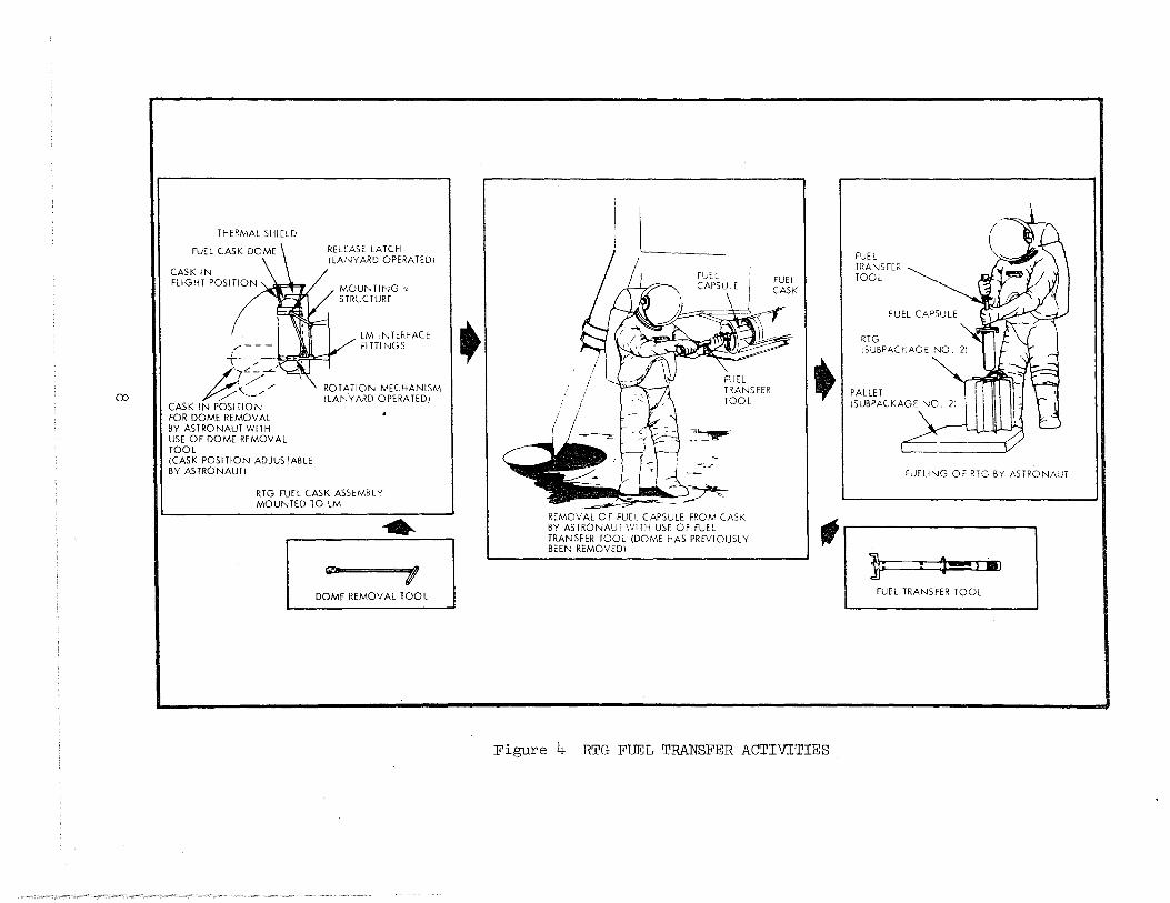
THERMAL SHIELD
CASK IN FLIGHT POSITION
,....---
RELEASE LATCH (LANYARD OPERA TED I
LM INTERFACE Fl TTl NGS
T----~ ?::;:;---: ,/)
. /
/"··-" CASK IN POSITION FOR DOME REMOVAL BY ASTRONAUT WITH USE OF DOME REMOVAL TOOL (CASK POSITION ADJUSTABLE BY ASTRONAUT!
ROTATION MECHANISM (LANYARD OPERATED)
RTG FUEL CASK ASSEMBLY MOUNTED TO LM
• ~ I
DOME REMOVAL TOOL
• L
FUEL TRANS FER TOOL
""~
REMOVAL 0 F FUEL CAPSULE FROM CASK BY ASTRONAUT WITH USE OF FUEL TRANSFER TOOL (DOME HAS PREVIOUSLY BEEN REMOVED!
FUEL CASK
• t
Figure 4 RTG FUEL TRANSFER ACTIVITIES
FUEL TRANSFER TOOL
FUELING OF RTG BY ASTRONAUT
l : ~ '81
FUEL TRANSFER TOOL
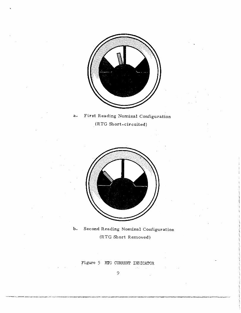
a. First Reading Nominal Configuration
(R TG Short-circuited)
b. Second Reading Nominal Configuration
(R TG Short Removed)
Figure 5 RTG CURRENT INDICATOR
9
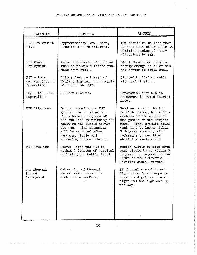
PARAMETER
PSE Deployment Site
PSE Stool Deployment
PSE - to -Central Station Separation
PSE - to - RTG Separation
PSE Alignment
PSE Leveling
PSE Thermal Shroud Deployment
PASSIVE SEISMIC EXPERIMENT DEPLOYMENT CRITERIA
CRITERIA
Approximately level spot, free from loose material.
Compact surface material as much as possible before putting down stool.
8 to 9 feet southeast of Central Station, on opposite side from the RTG.
15-feet minimum.
Before removing the PSE girdle, coarse align the PSE within 20 degrees of the sun line by pointing the arrow on the girdle toward the sun. Fine alignment will be reported after removing girdle and spreading thermal shroud.
Coarse level the PSE to within 5 degrees of vertical utilizing the bubble level.
Outer edge of thermal shroud skirt should be flat on the surface.
10
REMARKS
PSE should be no less than 10 feet from other units to minimize pickup of stray vibrations by PSE.
stool should not sink in deeply enough to allow sensor bottom to touch soil.
Limited by 10-foot cable with 1-foot slack.
Separation from RTG is necessary to avoid thermal input.
Read and report, to the nearest degree, the intersection of the shadow of the gnomon on the compass rose. Final azimuth alignment must be known within 5 degrees accuracy with reference to sun line utilizing shadowgraph.
Bubble should be free from case circle to be within 5 degrees. 5 degrees is the limit of the automatic . leveling gimbal system.
If thermal shroud is not flat on surface, temperature could get too low at night and too high during the day.
PASSIVE SEISMIC EXPERIMENT DEPLOYMENT CR!TERIA (Continued)
PARAMETER
Photographic Requirements
Precautions
CRITERIA
One photograph of the PSE taken cross-sun from a distance of 3 feet and showing the bubble level and the gnomon shadow on the compass rose.
One photograph of the PSE taken from a distance of 7 feet and showing the Central Station in the background.
REMARKS
The Hasselblad electric data camera should be used to take these photographs.
Tunneling, tenting or folding of the thermal skirt must be avoided to prevent the formation of radiative heat paths.
If necessary, Boyd bolts, small lunar rocks or similar small objects may be placed on the outer edge of the thermal skirt to hold it flat. Avoid placing large objects or dirt on the skirt, if possible.
11
PARAMETER
RFE Electronics Package
· HFE Site Selection
HFE Aligrunent
HFE Leveling
HEAT FLOW EXPERIMENT DEPLOYMENT CRITERIA
CRITERIA
Deploy the HFE Electronics Package 25 to 30 feet south of Central Station.
Align the HFE Electronics Package to within 5 degrees of the shadow line decal utilizing the shadowgraph.
Level the HFE Electronics Package to within 5 degrees of vertical for maximum utilization of the thermal sunshield utilizing the bubble level.
13
REMARKS
Limited by 30-foot cable. HFE Electronics Package should be placed in an approximately level area, removed from any surface irregularities or rocks that may obscure the field-of-view of the HFE sunshield reflector.
Radiator must face south away from equator and the Central Station. Alignment of HFE package is accomplished by rotating package until shadow cast by UHT covers alignment decal.
Bubble should be free from case circle to be within 5 degrees.
HEAT FLOW EXPERIMENT DEPLOYMENT CRITERIA (Continued)
PARAMETER
HFE Probes
HFE Probe Deployment
HFE Probe-toProbe Separation
HFE Bore Holes
Precautions
CRITERIA
Deploy the Probes 16 to 18 feet east-west of the HFE Electronics Package along the sun line .
HFE Probe-to-Probe separation should be at least 30 feet.
Use the Apollo Lunar Surface Drill to make a lined bore hole greater than 2,3 meters deep in the lunar surface and align the HFE Probe to within 15 degrees of vertical.
REMARKS
Probe cables should not be crossed.
Limited by length of cable. Maintain a 30-foot minimum separation between Probe and RTG.
The HFE probes should be 20 feet minimum from the PSE, 30 feet minimum from the RTG, 35 feet minimum from the LSM, and at least 10 feet from all other experiments.
Each hole should be l~ diameters from the rims of "fresh" craters more than l meter across.
Each hole should be 3 or more diameters from boulders more than l meter across.
Try to avoid having a "fresh" crater greater than 2 meters across between bore holes.
Try to avoid having a "fresh" crater greater than 5 meters across between the HFE bore holes and the core sample hole.
Disturbance of the lunar surface within 17' of probes to be minimal.
Once the probe is in the hole, do not try to remove it. Bottom hole latching Will be damaged.
14
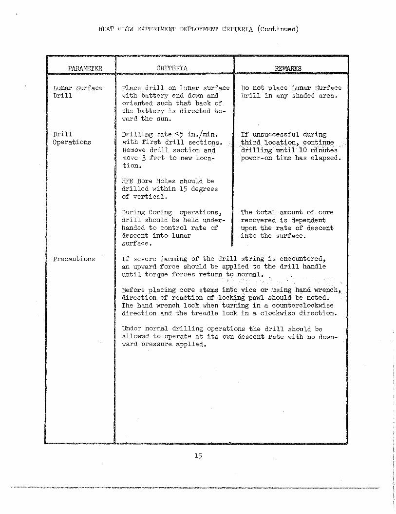
HEAT FLOW EXPERIMENT DEPLOYMENT CRITERIA (Continued)
PARAMETER
Lunar Surface Drill
Drill Operations
Precautions
CRITERIA
Place drill on lunar surface with battery end down and oriented such that back of the battery is directed toward the sun.
Drilling rate <5 in./min. with first drill sections. Remove drill section and move 3 feet to new location.
HFE Bore Holes should be drilled within 15 degrees of vertical.
During Coring operations, drill should be held underhanded to control rate of descent into lunar surface.
REMARKS
Do not place Lunar Surface Drill in any shaded area.
If unsuccessful during third location, continue drilling until 10 minutes power-on time has elapsed.
The total amount of core recovered is dependent upon the rate of descent into the surface.
If severe jamming of the drill string is encountered, an upward force should be applied to the drill handle until torque forces return to normal.
Before placing core stems into vice or using hand wrench, direction of reaction of locking pawl should be noted. The hand wrench lock when turning in a counterclockwise direction and the treadle lock in a clockwise direction.
Under normal drilling operations the drill should be allowed to operate at its own descent rate with no downward pressure applied.
15
HEAT FLOW EXPERIMENT DEPLOYMENT CRITERIA (Continued)
PARAMETER
Photographic Requirements
CRITERIA
One photograph o~ each bore stem with probe emplaced taken down-sun at a distance o~ 11 ~eet.
One photograph o~ the HFE electronics package taken ~rom the north at a distance o~ 7 feet.
One stereo pair o~ each bore stem with probe emplaced, taken ~rom the north at a distance o~ 7 ~eet.
16
REMARKS
These photographs should be taken with the Hasselblad electric data camera a~ter the HFE deployment is completed.
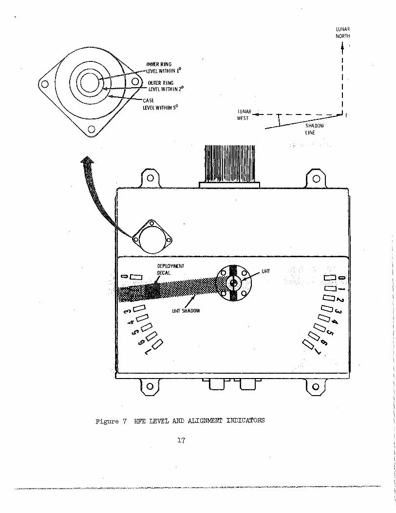
INNER RING LEVEL WITHIN 1°
OUTER RING J...l--~-+- LEVEL WITHIN z0
UHT SHADOW
LUNAR NORTH
t ' I I I I I I
LUNAR.._~£ WEST
SHAD.OW liNE
UHT
Figure 7 HFE LEVEL AND ALIGNMENI' INDICATORS
17
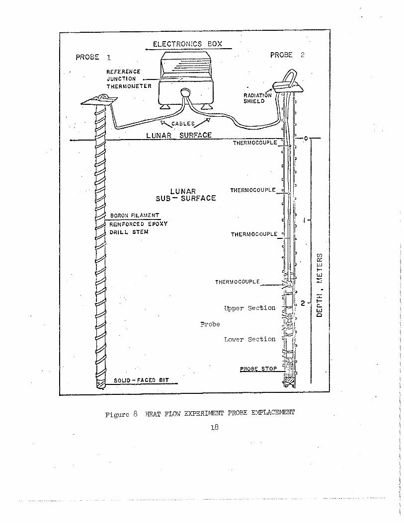
ELECTRONICS BOX
PROBE 1
THERMOMETER
L-:::;:::;:;;:::::.-;;::::::.~~c.A e L E s /
LUNAR SURFACE
LUNAR SUB- SURFACE
BORON FILAMENT
REJNFORCED EPOXY DRILL STEf~
PROBE 2
ro
f THERMOCOUPLE c J
.:
J I I t 1 I
THERMOCOUPLE ~ t'
l j r . I I
THERMOCOUPLE ~ l _____...~. r
Probe
~ 2 Upper Section ,
1l
~:r ;;cr I, : b
Lower Section \! ll!o
" :1
~lr PROBE STOP ~:UJ.I,~
~~I SOLID- FACED BIT
Figure 8 HEAT FLOW EXPERIMENT PROBE EMPLACEMENT
18
...... ~ c.. w 0
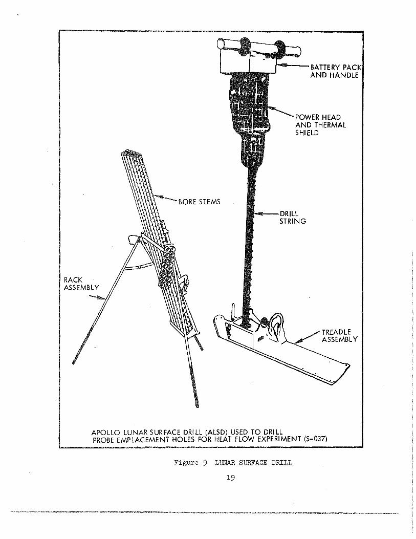
BORE STEMS
BATTERY PACK AND HANDLE
POWER HEAD AND THERMAL SHIELD
. .,...__DRILL STRING
APOLLO LUNAR SURFACE DRILL (ALSD) USED TO DRILL
TREADLE ASSEMBLY
PROBE EMPLACEMENT HOLES FOR HEAT FLOW EXPERIMENT (S-037)
Figure 9 LUNAR SURFACE DRILL
19
PARAMETER
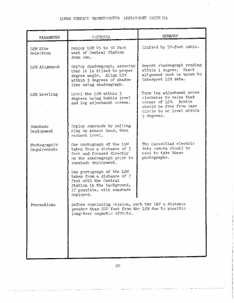
LSM Site Selection
LSM Alignment
LSM Leveling
Sunshade Deployment
Photographic Requirements
Precautions
LUNAR SURFACE MAGNETOMETER DEPLOYMENT CRITERIA
CRITERIA
Deploy LSM 45 to 50 feet west of Central Station down sun.
Deploy Shadowgraph, assuring that it is tilted to proper degree angle. Align LSM within 3 degrees of shadow line using shadowgraph.
Level the LSM within 3 degrees using bubble level and leg adjustment screws.
Deploy sunshade by pulling ring on sensor head, then recheck level.
One photograph of the LSM taken from a distance of 3 feet and focused directly on the shadowgraph prior to sunshade deployment.
One photograph of the LSM taken from a distance of 7 feet with the Central station in the background, if possible, with sunshade deployed.
REMARKS
Limited by 50-foot cable.
Report shadowgraph reading within l degree. Exact alignment must be known to interpret LSM data.
Turn leg adjustment screw clockwise to raise that corner of LSM. Bubble should be free from case circle to be level within 3 degrees.
The Hasselblad electric data camera should be used to take these photographs.
Before concluding mission, park the LRV a distance greater than 200 feet from the LSM due to possible long-term magnetic effects.
20
. _____ .....,._.....,J,
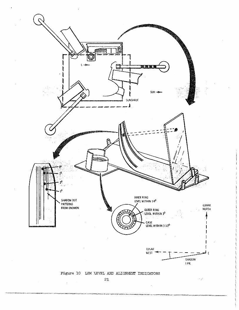
SHADOW DOT PATTERNS FROM GNOMON
----------
LUNAR NORTH
LUNAR I WEST .....,._ - T - - - ~ E
~w LINE
Figure 10 LSM LEVEL AND ALIGNMENT INDICATORS
21
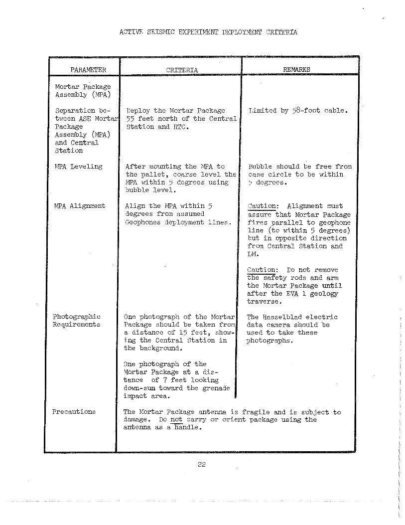
PARAMETER
Mortar Package Assembly (MPA)
Separation between ASE Mortar Package Assembly (MPA) and Central Station
MPA Leveling
MPA Alignment
Photographic Requirements
Precautions
ACTIVE SEISMIC EXPERIMENT DEPLOYMENT CRITERIA
CRITERIA
Deploy the Mortar Package 55 feet north of the Central Station and RTG.
After mounting the MPA to the pallet, coarse level the MPA within 5 degrees using bubble level.
Align the MPA within 5 degrees from assumed Geophones deployment lines.
One photograph of the Mortar Package should be taken from a distance of 15 feet, showing the Central Station in the background.
One photograph of the Mortar Package at a distance of 7 feet looking down-sun toward the grenade impact area.
REMARKS
Limited by 58-foot cable.
Bubble should be free from case circle to be within 5 degrees.
Caution: Alignment must assure that Mortar Package fires parallel to geophone line (to within 5 degrees) but in opposite direction from Central Station and LM.
Caution: Do not remove the safety rods and arm the Mortar Package until after the EVA 1 geology traverse.
The Hasselblad electric data camera should be used to take these photographs.
The Mortar Package antenna is fragile and is subject to damage. Do not carry or orient package using the antenna as a handle.
22
ACTIVE SEISMIC EXPERIMENT DEPLOYMENT CRITERIA (Continued)
PARAMETER
Geophones
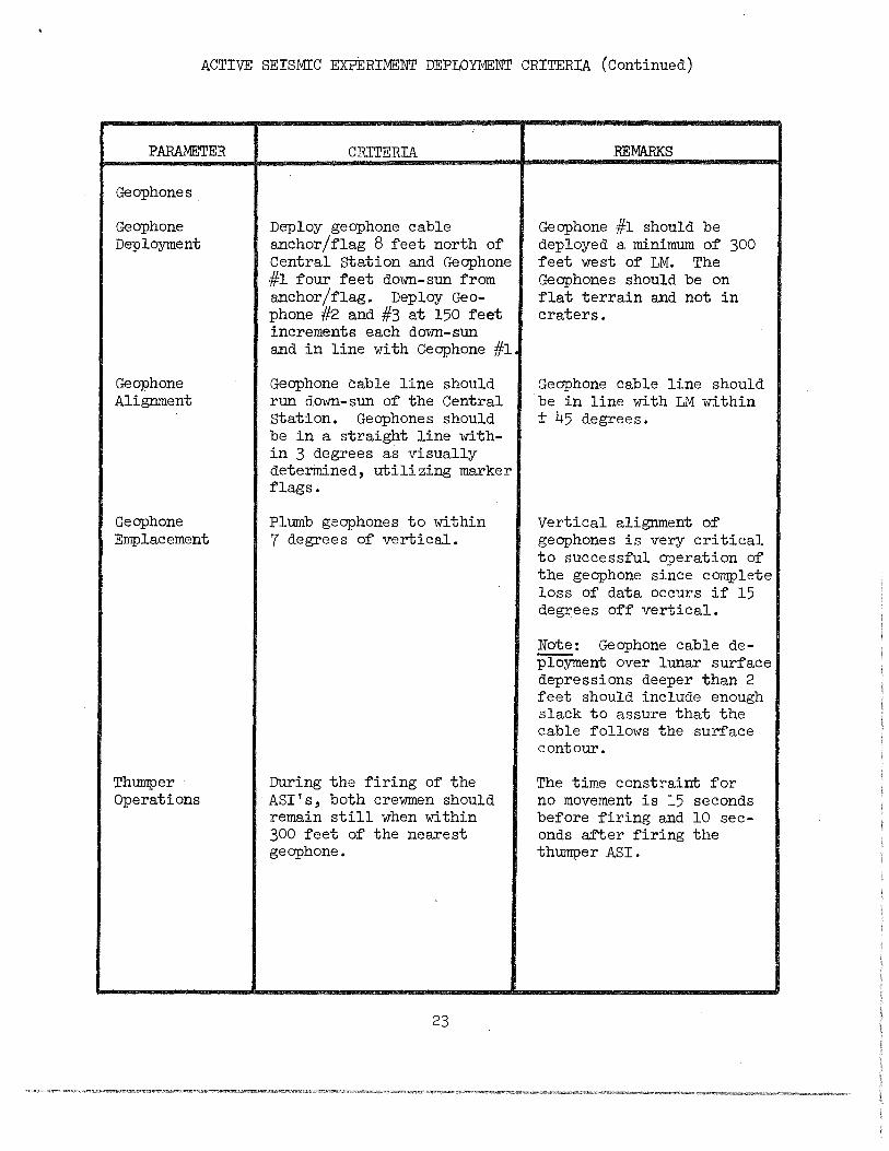
Geophone Deployment
Geophone Alignment
Geophone Emplacement
Thumper Operations
CRITERIA
Deploy geophone cable anchor/flag 8 feet north of Central Station and Geophone #1 four feet down-sun from anchor/flag. Deploy Geephone #2 and #3 at 150 feet increments each down-sun and in line with Geophone #1
Geophone cable line should run down-sun of the Central Station. Geophones should be in a straight line within 3 degrees as visually determined, utilizing marker flags.
Plumb geophones to within 7 degrees of vertical.
During the firing of the ASI's, both crewmen should remain still when within 300 feet of the nearest geophone.
23
REMARKS
Geophone #1 should be deployed a minimum of 300 feet west of LM. The Geophones should be on flat terrain and not in craters.
Geophone cable line should be in line with LM within ± 45 degrees.
Vertical alignment of geophones is very critical to successful operation of the geophone since complete loss of data occurs if 15 degrees off vertical.
Note: Geophone cable deployment over lunar surface depressions deeper than 2 feet should include enough slack to assure that the cable follows the surface contour.
The time constraint for no movement is 15 seconds before firing and 10 seconds after firing the thumper ASI.
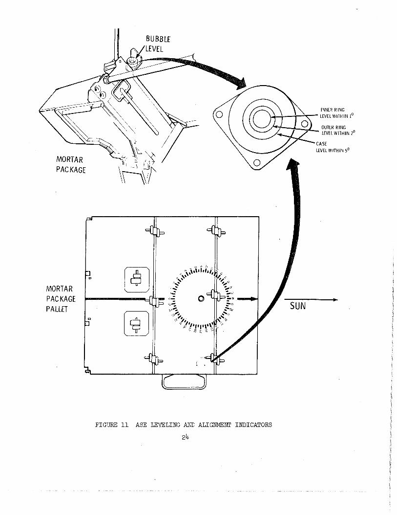
MORTAR PACKAGE
MORTAR PACKAGE PALLET
c
c
[!] "'"'\.!.#,,: s~, 9, .. a,-. ?~ -,_ -o-::
3:,-:.
...,a.--:,
~ ,, ... ~
~ ~· ., , 'I• "'"? ,.,.,. '\1 ~ ~ '£
INNER RING \.+.4---T--"'1::-- LEVEL WITHIN !0
SUN
FIGURE 11 ASE LEVELING AND ALIGNMENT INDICATORS
24
1\) \Jl
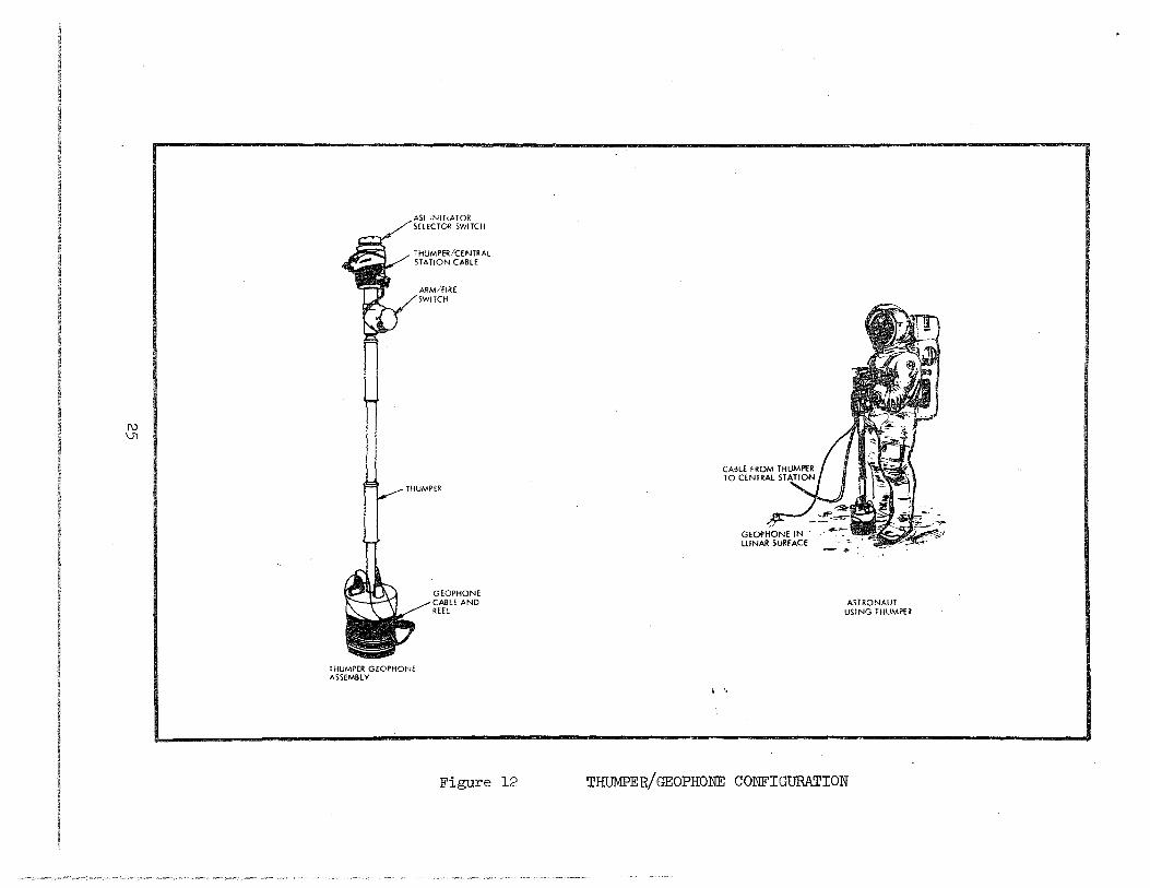
ASI INITIATOR SELECTOR SWITCH
THUMPER/CENTRAL STATION CABLE
1 HUMPER GEOPHONE ASSEMBLY
ARMIFIRE SWITCH
GEOPHONE CABLE AND REEL
Figure 12
I •,
ASTRONAUT USING THUMPER
THUMPER/GEOPHONE CONFIGURATION
LUNAR PORI'ABLE .MAGNETOMETER EXPERIMEJilT DEPLOYMEJilT CRITERIA
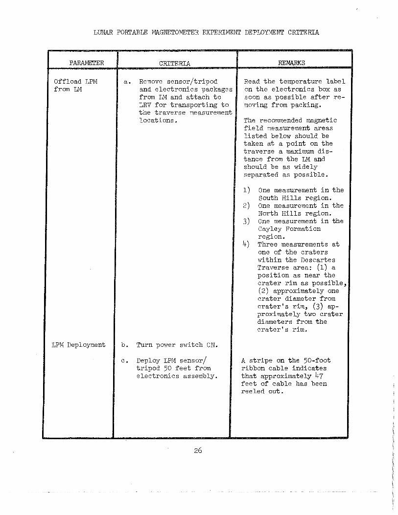
PARAMETER
Of'f'load LPM f'rom LM
LPM Deployment
CRITERIA
a. Remove sensor/tripod and electronics packages f'rom LM and attach to LRV f'or transporting to the traverse measurement locations.
b. Turn power switch ON.
c. Deploy LPM sensor/ tripod 50 f'eet f'rom electronics assembly.
26
REMARKS
Read the temperature label on the electronics box as soon as possible af'ter removing f'rom packing.
The recommended magnetic f'ield measurement areas listed below should be taken at a point on the traverse a maximum distance f'rom the LM and should be as widely separated as possible.
1) One measurement in the South Hills region.
2) One measurement in the North Hills region.
3) One measurement in the Cayley Formation region.
4) Three measurements at one of' the craters within the Descartes Traverse area: (1) a position as near the crater rim as possible, (2) approximately one crater diameter f'rom crater's rim, (3) approximately two crater diameters f'rom the crater's rim.
A stripe on the 50-f'oot ribbon cable indicates that approximately 47 f'eet of' cable has been reeled out.
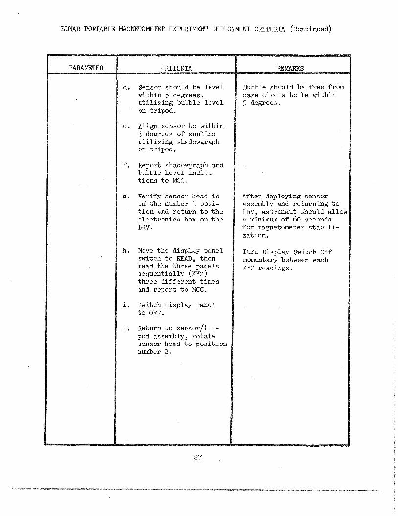
LUNAR PORTABLE MAGNETOMETER EXPERIMENT DEPLOYMENT CRITERIA (Continued)
PARAMETER CRITERIA
d. Sensor should be level within 5 degrees, utilizing bubble level on tripod.
e. Align sensor to within 3 degrees of sunline utilizing shadowgra:ph on tripod.
f. Report shadowgra:ph and bubble level indications to MCC.
g. Verify sensor head is in the number l :position and return to the electronics box on the LRV.
h. Move the display :panel switch to READ, then read the three :panels sequentially (XYZ) three different times and report to MCC.
i. Switch Display Panel to OFF.
j. Return to sensor/tripod assembly, rotate sensor head to :position number 2.
27
REMARKS
Bubble should be free from case circle to be within 5 degrees.
After deploying sensor assembly and returning to LRV, astronaut should allow a minimum of 60 seconds for magnetometer stabilization.
Turn Display Switch Off momentary between each XYZ readings.
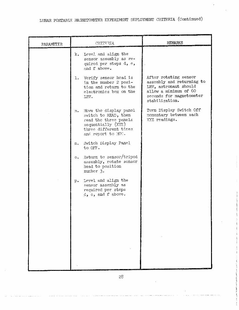
LUNAR PORTABLE MAGNETOMETER EXPERIMENT DEPLOYMENT CRITERIA (Continued)
PARAMETER CRITERIA
k. Level and align the sensor assembly as required per steps d, e, and f above.
1. Verify sensor head is in the number 2 position and return to the electronics box on the LRV.
m. Move the display panel switch to READ, then read the three panels sequentially (XYZ) three different times and report to MCC.
n. Switch Display Panel to OFF.
o. Return to sensor/tripod assembly, rotate sensor head to position number 3.
p. Level and align the sensor assembly as required per steps d, e, and f above.
28
REMARKS
After rotating sensor assembly and returning to LRV, astronaut should allow a minimum of 60 seconds for magnetometer stabilization.
Turn Display Switch Off momentary between each XYZ readings.
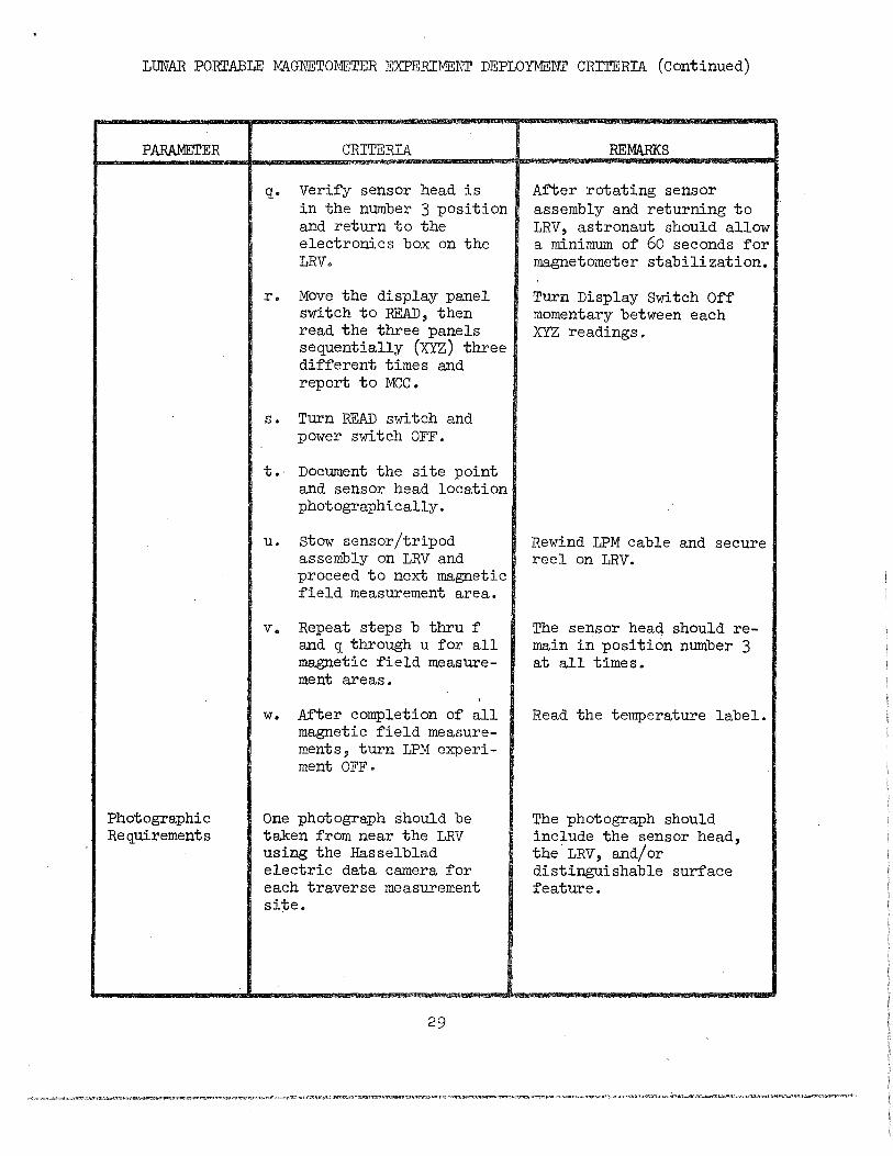
LUNAR PORTABLE MAGNETOMETER EXPERIMENT DEPLOYMENI' CRITERIA (Continued)
PARAMETER CRITERIA
Photographic Requirements
q. Verify sensor head is in the number 3 position and return to the electronics box on the LRV.
r. Move the display panel switch to READ, then read the three panels sequentially (XYZ) three different times and report to MCC •
s • Turn READ switch and power switch OFF.
t. Document the site point and sensor head location photographically.
u. stow sensor/tripod assembly on LRV and proceed to next magnetic field measurement area.
v. Repeat steps b thru f and q through u for all magnetic field measurement areas.
w. A:f'ter completion of all magnetic field measurements, turn LPM experiment OFF·
One :photograph should be taken from near the LRV using the Hasselblad electric data camera for each traverse measurement site.
29
REMARKS
After rotating sensor assembly and returning to LRV, astronaut should allow a minimum of 60 seconds for magnetometer stabilization.
Turn Display Switch Off momentary between each XYZ readings.
Rewind LPM cable and secure reel on LRV.
The sensor head should remain in position number 3 at all times.
Read the temperature label.
The photograph should include the sensor head, the.LRV, and/or distinguishable surface feature.
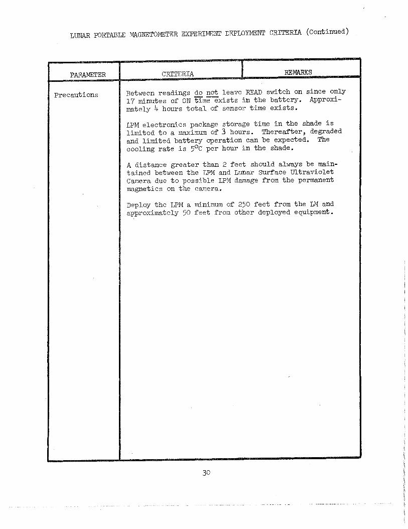
LUNAR PORTABLE :MAGNETOMETER EXPERIMENT DEPLOYMENT CRITERIA (Continued)
PARAMETER
Precautions
CRITERIA REMARKS
Between readings do not leave READ switch on since only 17 minutes of ON timeexists in the battery. Approximately 4 hours total of sensor time exists.
LPM electronics package storage time in the shade is limited to a maximum of 3 hours. Thereafter, degraded and limited battery operation c,an be expected. The cooling rate is 5°C per hour in the shade.
A distance greater than 2 feet should always be maintained between the LPM and Lunar Surface Ultraviolet Camera due to possible LPM damage from the permanent magnetics on the camera.
Deploy the LPM a minimum of 250 feet from the LM and approximately 50 feet from other deployed equipment.
30
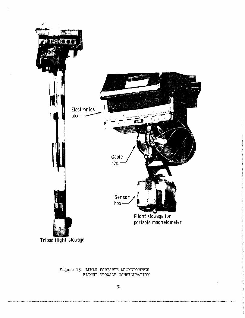
Electronics I box ______..- ,
-;;
I CabiJ reel
Flight stowage for portable magnetometer
Tripod flight stowage
Figure 13 LUNAR PORTABLE 'MAGNETOMETER FLIGHT STOWAGE CONFIGURATION
31
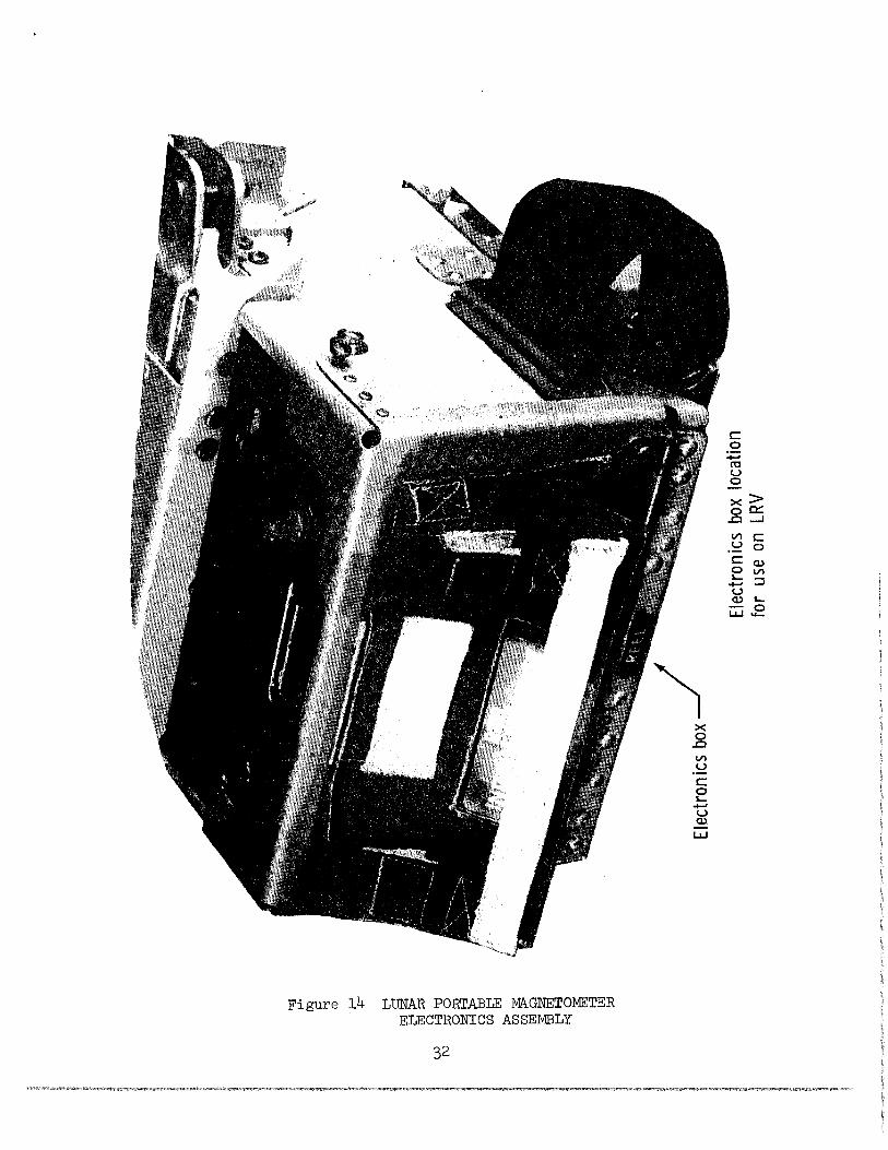
Figure 14 LUNAR PORTABLE MAGNETOMETER ELECTRONICS ASSEMBLY
32
X 0 .c Vl u c: e -u a.>.
LJ...J
c: 0 -ro u 0
x> oa:::: .c ......J
Vl c: .~ 0 c: Q.)
eVl ...-:::::l u Q.) L.
w:i.E
-~- --·----""'---
7 -/'~"-,
. ~'----,~ ~~
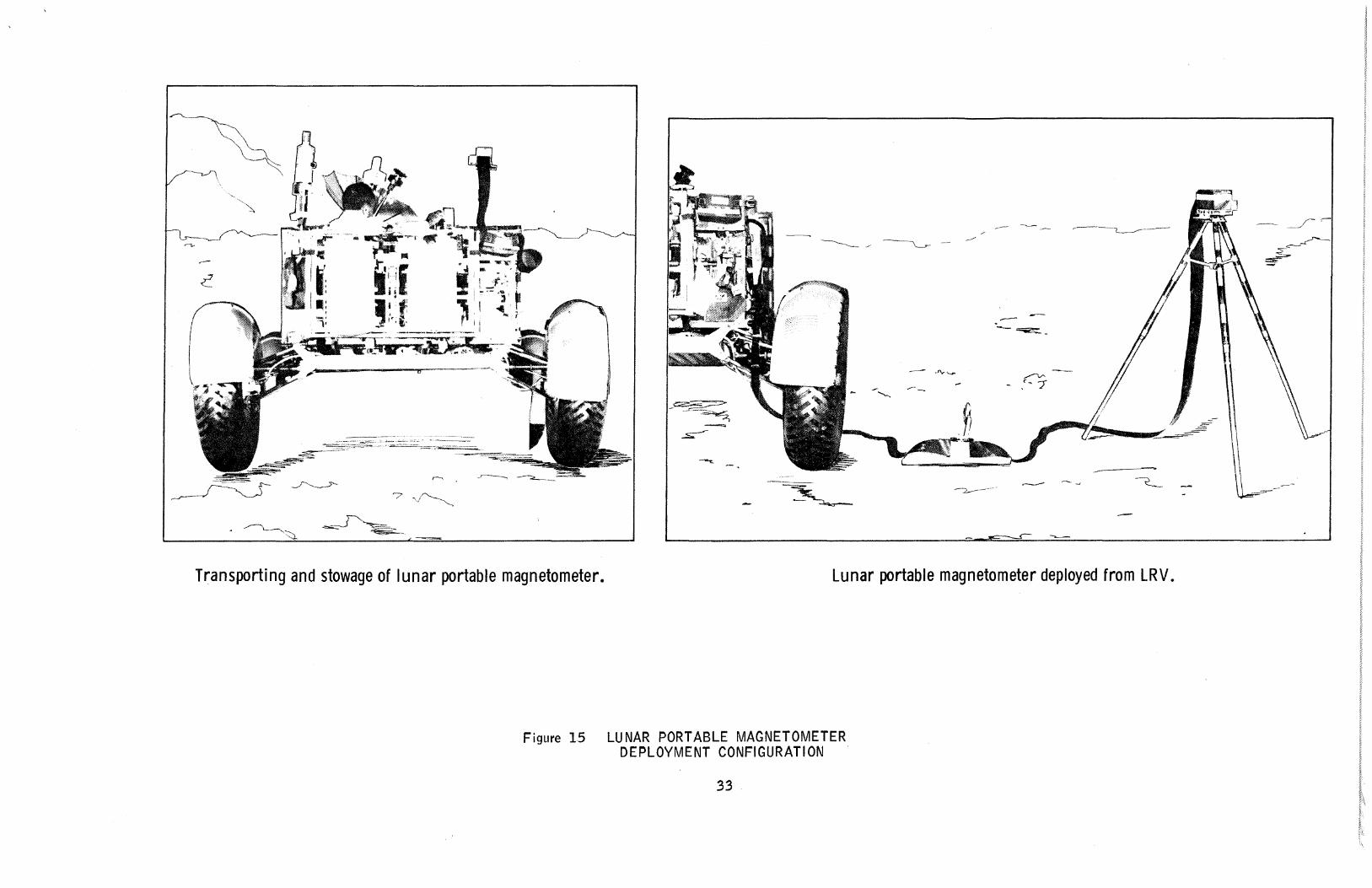
Transporting and stowage of lunar portable magnetometer. Lunar portable magnetometer deployed from LRV.
Figure 15 LUNAR PORT ABLE MAGNETOMETER DEPLOYMENT CONFIGURATION
33
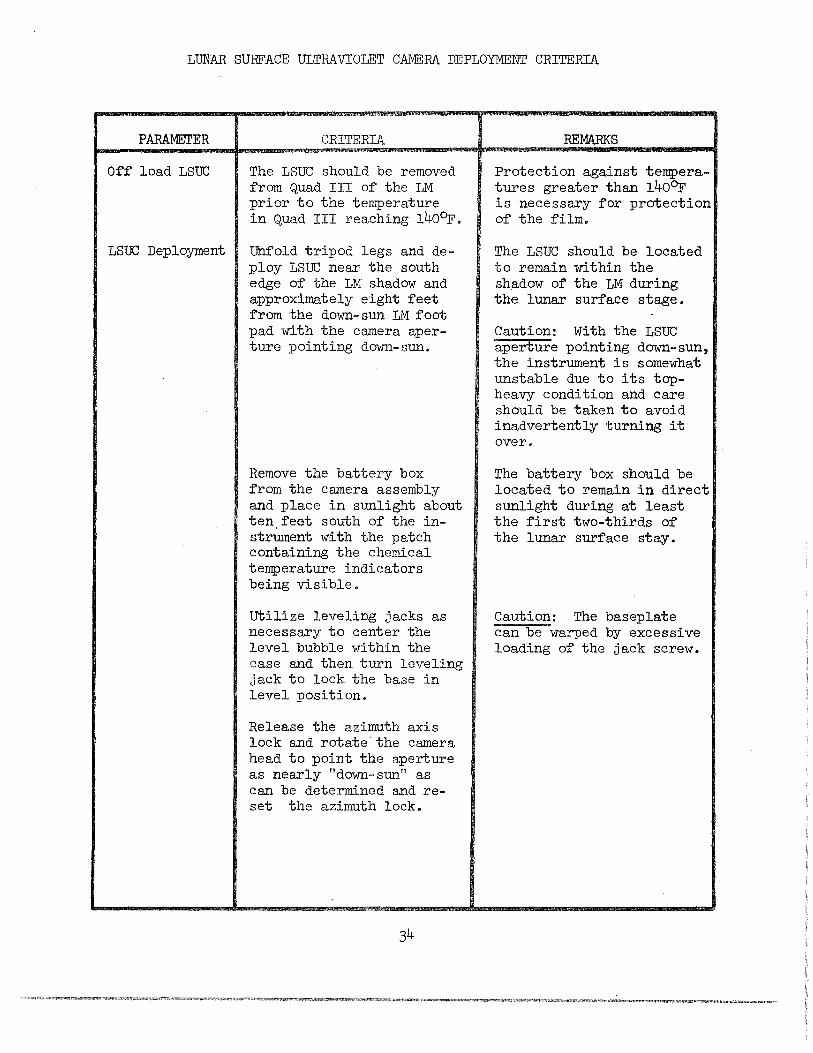
LUNAR SURFACE ULTRAVIOLET CAMERA DEPLOYMENT CRITERIA
PARAMETER
Off load LSUC
LSUC Deployment
CRITERIA
The LSUC should be removed from Quad III of the LM prior to the temperature in Quad III reaching 140Dr.
Unfold tripod legs and deploy LSUC near the south edge of the LM shadow and approximately eight feet from the down-sun 1M foot pad with the camera aperture pointing down-sun.
Remove the battery box from the camera assembly and place in sunlight about ten,feet south of the instrument with the patch containing the chemical temperature indicators being visible.
Utilize leveling jacks as necessary to center the level bubble within the case and then turn leveling jack to lock the base in level position.
Release the azimuth axis lock and rotate the camera head to point the aperture as nearly "down-sun" as can be determined and reset the azimuth lock.
REMARKS
Protection against temperatures greater than 140~ is necessary for protection of the film.
The LSUC should be located to remain within the shadow of the LM during the lunar surface stage.
Caution: With the LSUC aperture pointing down-sun, the instrument is somewhat unstable due to its topheavy condition and care should be taken to avoid inadvertently turning it over.
The battery box should be located to remain in direct sunlight during at least the first two-thirds of the lunar surface stay.
Caution: The baseplate can be warped by excessive loading of the jack screw.
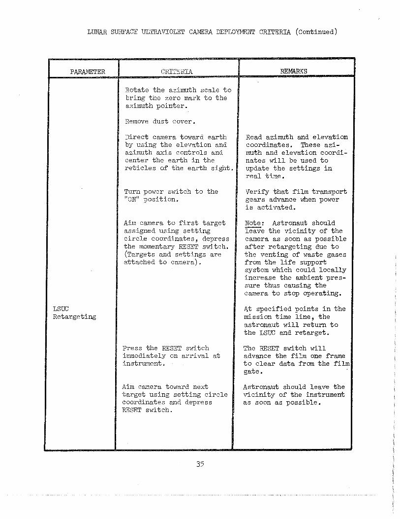
LUNAR SURFACE ULTRAVIOLET CAMERA DEPLOYMENT CRITERIA (Continued)
PARAMETER
LSUC Retargeting
CRITERIA
Rotate the azimuth scale to bring the zero mark to the azimuth pointer.
Remove dust cover.
Direct camera toward earth by using the elevation and azimuth axis controls and center the earth in the reticles of the earth sight.
Turn power switch to the "ON" position.
Aim camera to first target assigned using setting circle coordinates, depress the momentary RESET switch. (Targets and settings are attached to camera).
Press the RESET switch immediately on arrival at instrument.
Aim camera toward next target using setting circle coordinates and depress RESET switch.
35
REMARKS
Read azimuth and elevation coordinates. These azimuth and elevation coordi~ nates will be used to update the settings in real time.
Verify that film transport gears advance when power is activated.
Note: Astronaut should --leave the vicinity of the camera as soon as possible after retargeting due to the venting of waste gases from the life support system which could locally increase the ambient pressure thus causing the camera to stop operating.
At specified points in the mission time line, the astronaut will return to the LSUC and retarget.
The RESET switch will advance the film one frame to clear data from the film gate.
Astronaut should leave the vicinity of the instrument as soon as possible.
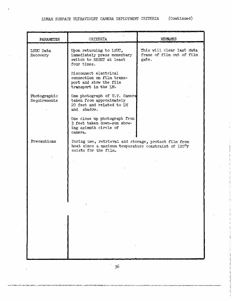
LUNAR SURFACE ULTRAVIOLET CAMERA DEPLOYMENT CRITERIA (Continued)
PARAMETER
LSUC Data Recovery
Photographic Requirements
Precautions
CRITERIA
Upon returning to LSUC, immediately press momentary switch to RESET at least four times.
Disconnect electrical connection on film transport and stow the film transport in the LM·
One photograph of u.v. Camers taken from approximately 20 feet and related to LM and shadow.
One close up photograph from 3.feet taken down-sun showing azimuth circle of camera.
REMARKS
This will clear last data frame of film out of film gate.
During use, retrieval and storage, protect film from heat since a maximum temperature constraint of 120~ exists for the film.
37
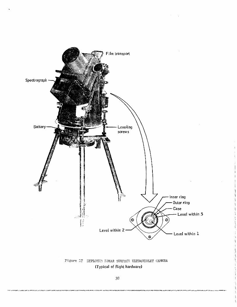
Spectrograph
Film transport
u--- Leveling screws
Inner ring
Outer ring
Case , ___ Level within 5
Level within 2
Figure 17 DEPLOYED LUNAR SURFACE ULTRAVIOLET CAMERA
<Typical of flight hardware)
38
Level within 1
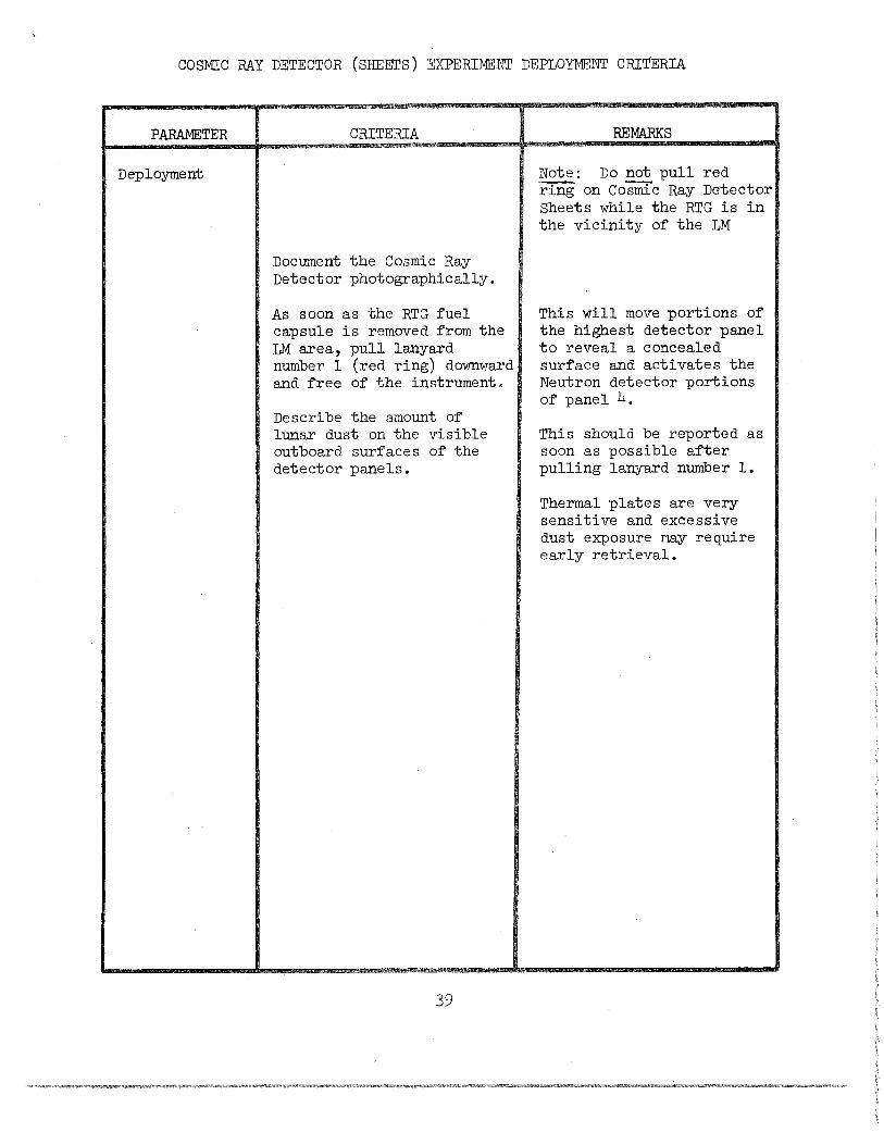
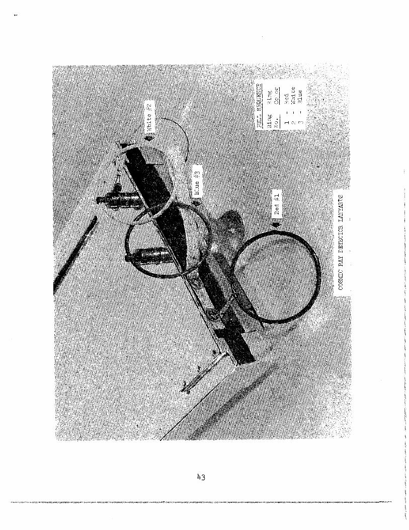
COSMIC RAY DETECTOR (SHEErS) EXPERIMENT DEPLOYMENT CRITERIA
Deployment
Document the Cosmic Ray Detector photographically.
As soon as the RTG fuel capsule is removed from the LM area, pull lanyard number 1 (red ring) downward and free of the instrument.
Describe the amount of lunar dust on the visible outboard surfaces of the detector panels.
39
Note: Do not pull red ring on Cosmic Ray Detector Sheets while the RTG is in the vicinity of the LM
This will move portions of the highest detector panel to reveal a concealed surface and activates the Neutron detector portions of panel 4.
This should be reported as soon as possible after pulling lanyard number 1.
Thermal plates are very sensitive and excessive dust exposure may require early retrieval.
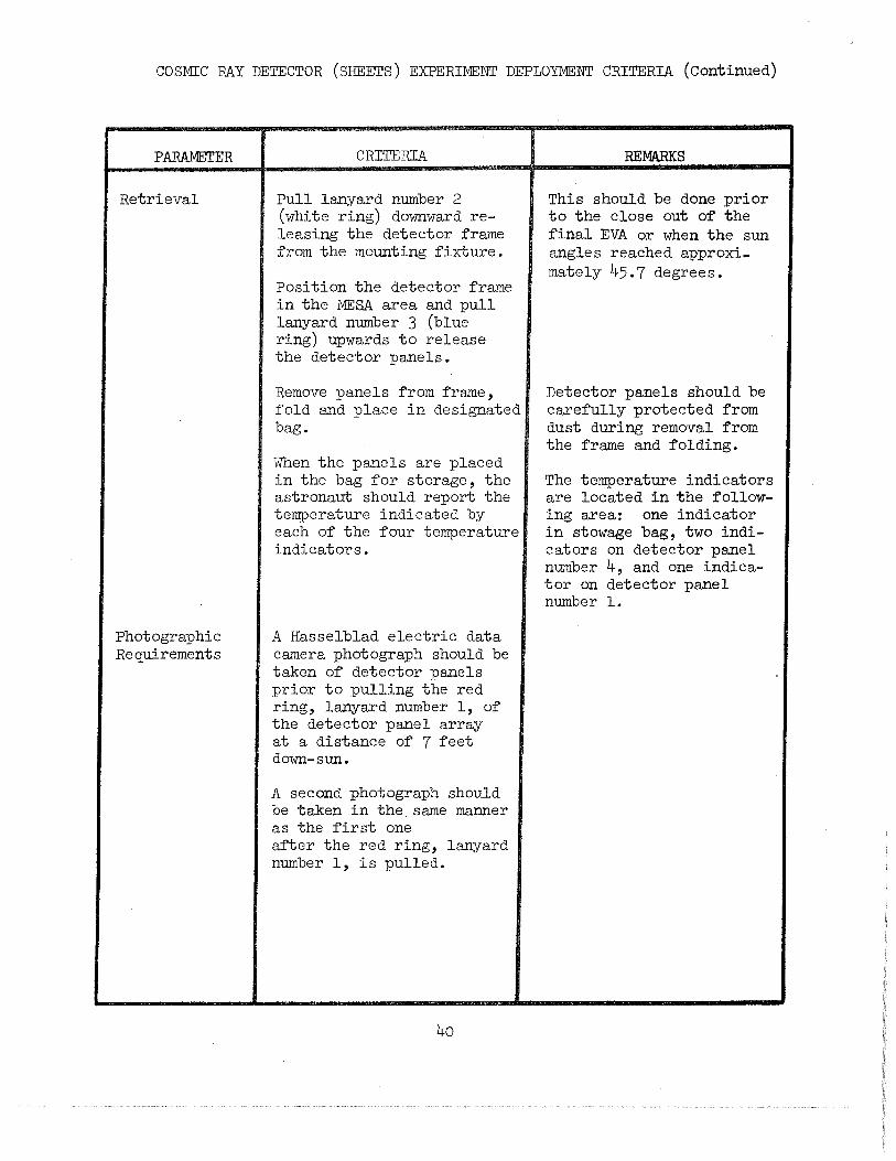
COSMIC RAY DETECTOR (S11EETS) EXPERIMENT DEPLOYMENT CRITERIA (Continued)
PARAMETER
Retrieval
Photographic Requirements
CRITERIA
Pull lanyard number 2 (white ring) downward releasing the detector frame from the mounting fixture.
Position the detector frame in the MESA area and pull lanyard number 3 (blue ring) upwards to release the detector :panels.
Remove :panels from frame, fold and :place in designated bag.
When the :panels are :placed in the bag for storage, the astronaut should report the temperature indicated by each of the four temperature indicators.
A Hasselblad electric data camera :photograph should be taken of detector :panels :prior to :pulling the red ring, lanyard number 1, of the detector :panel array at a distance of 7 feet down-sun.
A second :photograph should be taken in the same manner as the first one after the red ring, lanyard number 1, is pulled.
40
REMARKS
This should be done :prior to the close out of the final EVA or when the sun angles reached approximately 45.7 degrees.
Detector :panels should be carefully :protected from dust during removal from the frame and folding.
The temperature indicators are located in the following area: one indicator in stowage bag, two indicators on detector :panel number 4, and one indicator on detector panel number l.
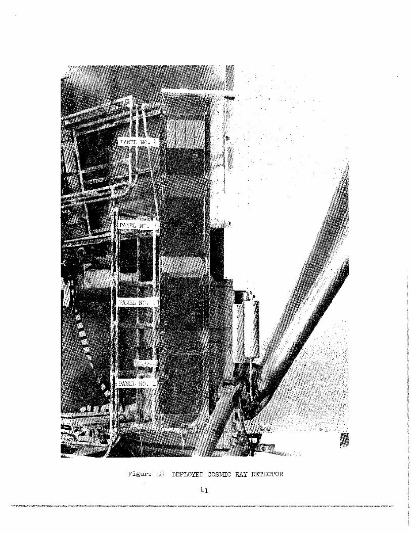
Figure 18 DEPLOYED COSMIC RAY DETECTOR
41
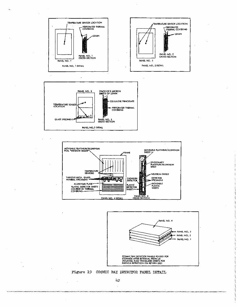
TEMPERATURE SENSOR LOCATION
I THERMAL ..-----+-/.....,
I
PANEL NO. I
PANEL NO. I CROS5-SECTION
PANEL NO. I DETAIL
STACK OF 5 MICRON SHEETS OF LEXAN
TERMPERA TURE SENSOR· LOCATION JELLULOSE TRIACETATE
PERFORATED THERMAL COVERING
PANEL NO, 3 CROSS. SECTION
PANEL N0.3 DETAIL
MOVEABLE PLATINUM/ALUMINUM FOIL "WINDOW SHADE"
-~~
VARIOUS MICA, MINERAL SPECIM
~i~~TURE !--
GLASS, ENS
1-- "'"
:::----c. ~ ....
/F
II II ......
UM PLATE ALUMIN PLASTIC DET COVERED B COVERING
ECTOR SHEETS ~000000000000
Y THERMAL -
ltAME
TEMPERATURE SENSOR LOCATION
PERFORATED THERMAL COVER! NG
LEXAN
PANEL NO.2 CROSS-SECTION
PANEL NO.2
PANEL NO. 2 DETAIL
MOVEABLE PLATINUM/ALUMINUM SHEET
NEUTRON SHIELD
DETECTOR SPECIMENS MOVEABLE PLASTIC SHEETS
PANEL NO.3
PANEL NO.2
·PANEL NO. I
COSMIC RAY DETECTOR PANELS FOLDED FOR STOWAGE AFTER RETRIEVAL FROM LM (FOLDING ALSO TRANSLATES SHEETS FOR PARTICLE DETECTION ON RETURN LEG)
Figure 19 COSMIC RAY DETECTOR PANEL DETAIL
42
43
PARAMETER
SWC Deployment
Photographic Requirements
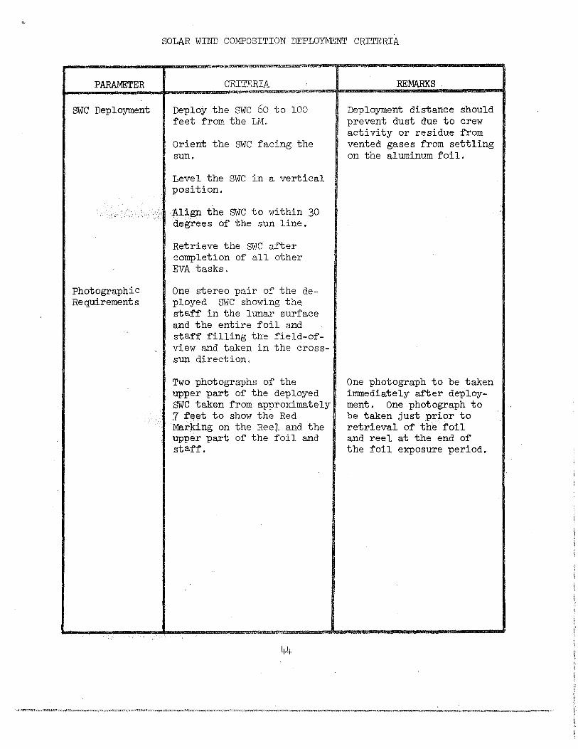
SOLAR WIND COMPOSITION DEPLOYMENT CRITERIA
CRITERIA
Deploy the SWC 60 to 100 feet from the LM.
Orient the SWC facing the sun.
Level the SWC in a vertical position.
Align the SWC to within 30 degrees of the sun line.
Retrieve the SWC after completion of all other EVA tasks,
One stereo pair of the deployed SWC showing the. staff in the lunar surface and the entire foil and staff filling the field-ofview and taken in the crosssun direction.
Two photographs of the upper part of the deployed SWC taken from approximately 7 feet to show the Red Marking on the Ree~ and the upper part of the foil and staff.
44
REMARKS .
Deployment distance should prevent dust due to crew activity or residue from vented gases from settling on the aluminum foil.
One photograph to be taken immediately after deployment. One photograph to be taken just prior to retrieval of the foil and reel at the end of the foil exposure period.
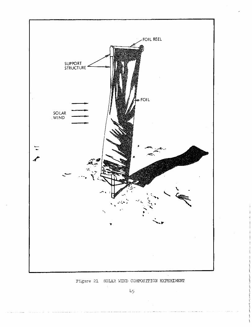
SOLAR .WIND
-.._ . ·-..
';
... . ..
_ ....... c. .. .t
FOIL REEL
~---~;...• ---.. ~,
\ -I •· .. ~
·-· ~. ~ ... " ""'., •
Figure 21 SOLAR WIND COMPOSITION EXPERIMENT
PARA.METER
Penetrometer Deployment
Penetrometer Measurement
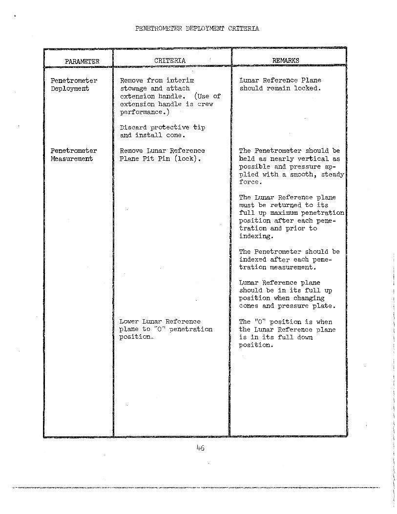
PENETROMETER DEPLOYMENT CRITERIA
CRITERIA
Remove from interim stowage and attach extension handle. (Use of extension handle is crew performance.)
Discard protective tip and install cone.
Remove Lunar Reference Plane Pit Pin (lock).
Lower Lunar Reference plane to "0" penetration position.
46
REMARKS
Lunar Reference Plane should remain locked.
The Penetrometer should be held as nearly vertical as possible and pressure applied with a smooth, steady force.
The Lunar Reference plane must be returned to its full up maximum penetration position after each penetration and prior to indexing.
The Penetrometer should be indexed after each penetration measurement.
Lunar Reference plane should be in its full up position when changing cones and pressure plate.
The "0" position is when the Lunar Reference plane is in its full down position.
PARAMETER
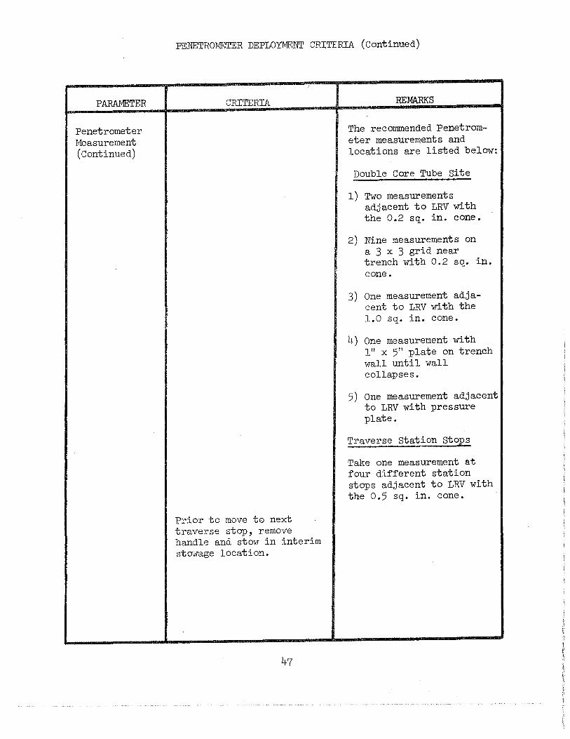
Penetrometer Measurement (Continued)
PENETROMETER DEPLOYMENT CRITERIA (Continued)
CRITERIA
Prior to move to next traverse stop, remove handle and stow in interim sto·;vage location.
47
REMARKS
The recommended Penetrometer measurements and locations are listed below:
Double Core Tube Site
l) Two measurements adjacent to LRV with the 0.2 sq. in. cone.
2) Nine measurements on a 3 x 3 grid near trench with 0.2 sq. in. cone.
3) One measurement adjacent to LRV with the 1.0 sq. in. cone.
4) One measurement with 1" x 5" plate on trench wall until wall collapses.
5) One measurement adjacent to LRV with pressure plate.
Traverse Station Stops
Take one measurement at four different station stops adjacent to LRV with the 0.5 sq. in. cone.
PARAMETER
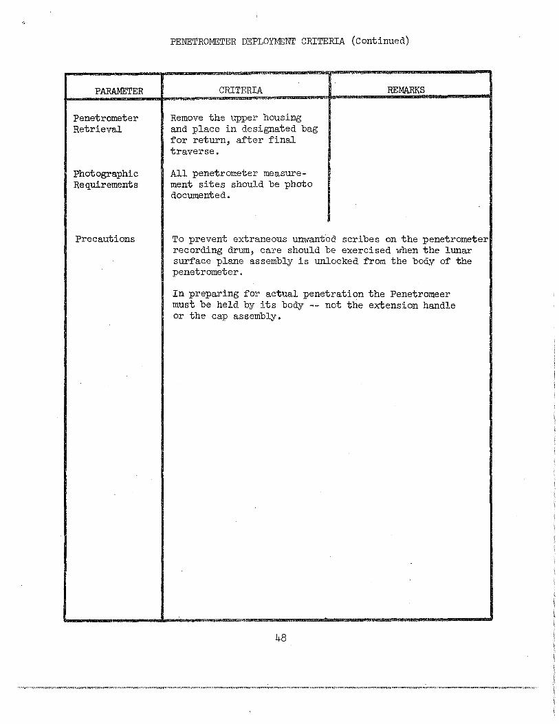
Penetrometer Retrieval
Photographic Requirements
Precautions
PENETROMETER DEPLOYMENT CRITERIA (Continued)
CRITERIA
Remove the upper housing and place in designated bag ~or return, ~er ~inal traverse.
All penetrometer measurement sites should be photo documented.
REMARKS
To prevent extraneous unwant-ed scribes on the penetrometer recording drum, care should be exercised when the lunar sur~ace plane assembly is unlocked ~rom the body o~ the penetrometer.
In preparing ~or actual penetration the Penetromeer must be held by its body -- not the extension handle or the cap assembly.
48
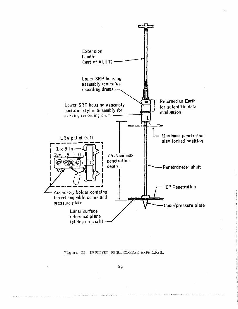
Extension handle (part of ALH T)
Upper SRP housing assembly (contains recording drum)
Lower SRP housing assembly contains stylus assembly for marking recording drum -----1'"
Accessory holder contains interchangeable cones and pressure plate
Lunar surface reference plane (slides on shaft)
76 .Scm max. penetration depth
Returned to Earth for scientific data evaluation
·-·~
. L Maximum penetration also locked position
.......___Penetrometer shaft
"0" Penetration
Figure 22 DEPLOYED PENETROMETER EXPERIMENT
49
SAMPLE RErlJRN CONTAINER CLOSEOtJr CRITERIA
'
PARAMETER CRITERIA REMARKS
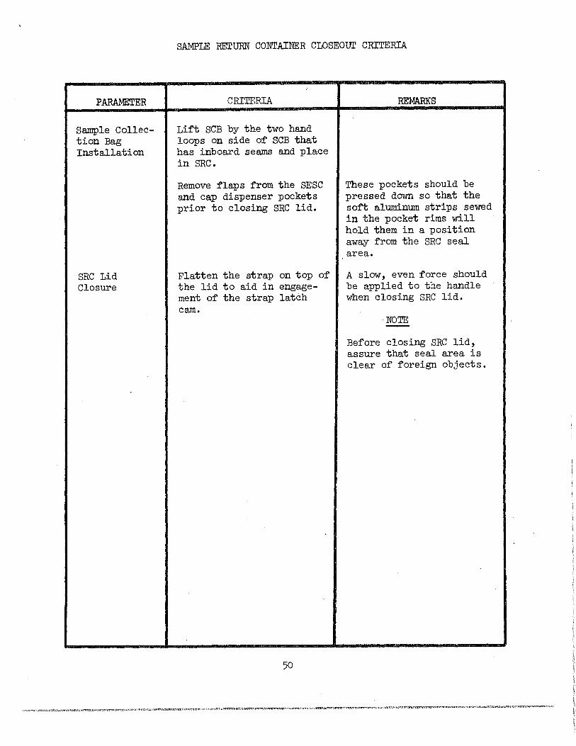
Sample Collec- Lift SCB by the two hand tion Bag loops on side of SCB that Installation has inboard seams and place
in SRC.
Remove flaps from the SESC These pockets should be and cap dispenser pockets pressed down so that the prior to closing SRC lid. soft aluminum strips sewed
in the pocket rims will hold them in a position away from the SRC seal area.
SRC Lid Flatten the strap on top of A slow, even force should Closure the lid to aid in engage- be applied to the handle
ment of the strap latch when closing SRC lid. cam.
NOTE -Before closing SRC lid, assure that seal area is clear of foreign objects.
50
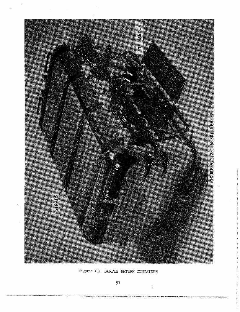
Figure 23 SAMPLE RETURN CONTAINER
51
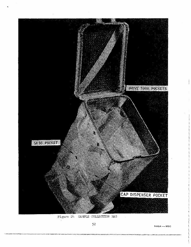
Figure 24 SAMPLE COLLECTION BAG
52 NASA-MSC