Embed Size (px)
Citation preview

NO. RIV. NO.
Final Reoort of Alsen Cask Cooling Feasibility Study
ATM-763
1 PAGE
87 OP
DATE 1 April 1968
ALSEP CASK COOLING
FEASIBILITY STUDY
Prepared by ..L5 Mrafi-/,.srfB. Nordquist
Approved by y';z;/?~~ Y.L: McNaughton

Aerospace Systems Division
ALSEP Cask Cooling Feasibility Study
1. 0 INTRODUCTION
1. 1 Background 1. 2 Review of Cask Cooling Requirements 1. 3 Study Objectives 1. 4 Description of Selected Concepts
2. 0 TEST RESULTS
2. 1 Discussion of Data 2. 2 Recommendations 2. 3 Test Setup 2. 4 Summary of Test Data
3. 0 THEORETICAL AND EXPERIMENTAL ANALYSIS
3. 1 Background 3. 2 Basic Open Flow Analysis 3. 3 Correlation of Open Flow to Theory 3. 4 Shroud Analysis
4. 0 THERMAL CORRELATION
5. 0 DISCUSSION OF PRE-TEST ANALYTICAL STUDIES
5. 1 Axial Flow Air Cooling Systems 5. 1. 1 Attached Nozzle - Open Flow 5. 1. 2 Detached Nozzle - Open Flow 5. 1. 3 Attached Nozzle - Shrouded Flow
5. 2 Cross Flow Cooling Systems 5. 3 Normal Flow Cooling Systems 5. 4 Water Cooling Systems
5. 4. 1 Closed System 5. 4. 2 Open System
5. 5 Cask Shroud Removal Investigation
NO. REV. NO.
ATM-763
PAGE 2 OF 87
DATE 4/1/68
Page
6
6 7 7 9
12
12 23 24 25
29
29 29 45 48
50
52
52 52 55 56 60 64 69 70 75 77

Aerospace Systems Division
Figure No.
1.1 1.2 2.1 a & b 2.2
2.3
2.4
2.5
2. 6
2. 7
3. 1 3. 2 3. 3 3.4 3. 5
3. 6 3. 7 5. 1
ALSEP Cask Cooling Feasibility Study
NO.
ATM-763
PAGE 3
REV. NO.
OF 87
DATE 4/1/68
LIST OF FIGURES
Title
Early Cooling Cone epts Schematic of Test Nozzle Configurations Test Setup for Cask Cooling Series Open Side Cask Surface Temperatures
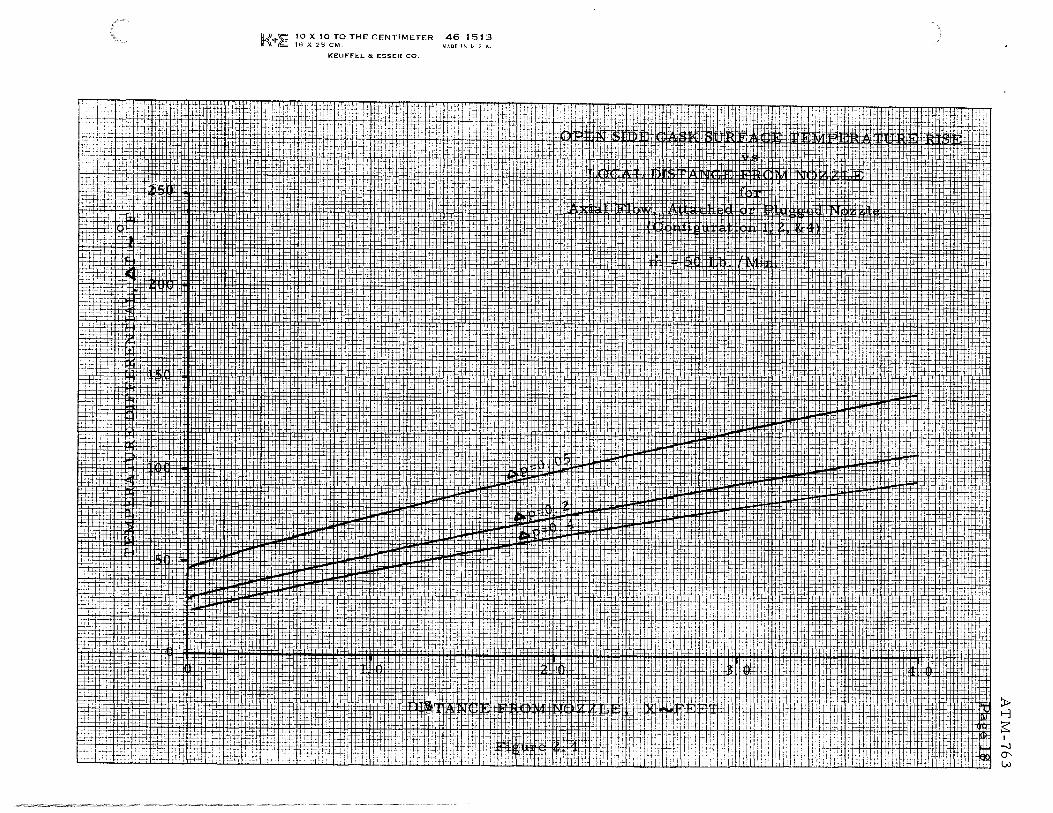
Axial flow, rn = 20 lb/ min Open Side Cask Surface Temperature Rise
Axial Flow, m = 35 lb/min Open Side Cask Surface Temperature Rise
Axial flow, rn = 50 lb/min Open Side Cask Surface Temperature Rise
Conical Nozzles, in= 20 lb/min Open Side Cask Surface Temperature Rise
Conical Nozzles, m = 35 lb/min Open Side Cask Surface Temperature Rise
Conical Nozzles, m = 50 lb/ min Jet Velocity for Attached Nozzle (Config. l) Jet Velocity for Attached Plugged Nozzle (Config. 2) Correlation of Surface Velocity Runs 1-12 (Config. 1) Correlation of Surface Velocity Runs 13-18, 30-35 (Config. Correlation of Surface Velocity Runs 19-21, 22-27, 28-29,
36-40 (Config. 3, 4, 5 & 6)
Page
10 11 13 16
17
18
19
20
21
32 33 36
2) 37 38
Two-Dimensional Jet Velocity m = 23 lb/min 6 p = . 10 psi 41 Two-Dimensional Jet Velocity m = 22lb/min, 6P = .135 psi 42 Normal Flow Open Shroud Purge System 65

. , . • :. I
==-Division
Table No.
I
II
III
IV
ALSEP Cask Cooling Feasibility Study
LIST OF TABLES
Title
Test Nozzle Configuration and Flow Conditions
Summary of Test Data
Equilibrium Temperatures
Cask Temperature Correlations
NO. REV. MO •
ATM-763
PAGE 4 OF 87
DATE 4/1/68
Page
22
26
28
51

: : t ~
Assigned No. Drawing No.
1. 2334911
2. 2335093
3. 2335343
4. 2335335
5. 2335355
6. 2335346
7. 2335347
8. 2334348
9. 2335349
NO. REV. NO.
ATM-763
ALSEP Cask Cooling Feasibility Study
LIST OF DRAWINGS
Title
Fuel Cask Mounting Assy
Axial Flow Purge System Assy
Axial Flow Purge System Assy No. 2
Axial Flow Purge System with Shroud
PAGE
DATE
Open and Closed Air/Water Shroud System
Fuel Cask Mounting As sy Instrumentation
Heat Shield Assy Instrumentation
Mounting Bracket Instrumentation
5 OF 87
4/1/68
Page
79
80
81
82
83
84
85
86
Fuel, Capsule, and Cask Assy Test Instrumentation 87

NO. REV. NO • . • : I ATM-763
PAGE 6 OF
Aerospace Systems Division
ALSEP Cask Cooling Feasibility Study
DATE 4/1/68
1. 0 INTRODUCTION
1. 1 Background
In June of 1967, NASA Headquarters held a review of the ALSEP Program as related to the overall Apollo mis sian safety. Specific attention was given to the safety aspects of the RTG fuel cask which maintains an on pad temperature of approximately 650°F. It was determined that such a temperature level would represent a potential ignition hazard to the vehicle propellant vapors. Therefore MSC requested that Bendix conduct a preliminary thermal study to determine the feasibility of reducing the graphite fuel cask surface temperature to a level below 400°F during the prelaunch operations.
The results of the thermal study were transmitted to MSC on June 27, 1968. The basic conclusion was that the surface temperature of the graphite cask could be maintained below 400°F if the cask were locally purged from a directed nozzle or orifice supplied with a cooling flow of 225 to 450 cfm, (17-35 lb/min) at 70°F.
As a consequence of this study, an RTG Cask/Ignition Source Committee was established with members from MSC, KSC, GAEC, Sandia, LeRC, and Bendix. The purpose of this committee was to evaluate the potential ignition source problem of the cask in the presence of the various vehicle fuel vapors and to establish the requirements for reducing the cask surface temperature in a manner consistent with existing flight hardware and KSC capability. The first meeting of the committee was held at MSC on August 10-11, 1968. As a result ot that meeting, Bendix was directed to submit a proposal to MSC for the purpose of conducting an engineering feasibility study and development te·sts to maintain the graphite cask surface below a maximum temperature of 350°F. The study was initiated on August 15, 1967 and was completeq: cin January 12, 1968. This report summarizes the analysis, design,'. a;pd test activities conducted at Bendix during that period.
87

NO. REV. NO.
: : . ATM-763
7 PAGE OF
~ Systems Division
ALSEP Cask Cooling Feasibility Study
DATE 4/1/68
1. 2 Review of Cask Cooling Requirements
The SNAP- 27 graphite fuel cask (GLFC) is located to the left of the ALSEP compartment in the LM SEQ bay. At approximately T-16 hours in the Apollo launch sequence, the fuel capsule assembly (FCA) is loaded into the cask. This FCA has a thermal energy output of 1500 watts and a surface temperature of approximately 1100°F, at the time of loading. Upon loading, the GLFC surface temperature rises from ambient to a free convection level between 550° and 650°F in approximately one hour. After vehicle liftoff and the subsequent loss of the convection portion of cooling to the cask, the GLFC surface temperature further increases to the range of 700° - 8000F.
It has been estimated that the spontaneous ignition temperature (SIT) of the command module and service module RCS propellant, monomethyl hyarazine (MMH) is of the order of 380°F - while the other vehicle propellants, UDMH and N2H4, have spontaneous ignition temperatures of 480° and 518°F respectively. Because of the possibility of propellant leakage from the A/S or LM fuel disconnects, supply lines, or the tanks themselves, the cask assembly presents a potential ignition hazard to the vehicle.
In order to reduce this hazard, it is necessary to actively cool any exposed cask surfaces to a temperature level below that of the aforementioned spontaneous ignition temperatures.
1. 3 Study Objectives
In order to guide the selection and evaluation of the various possible cask cooling systems, the following ground rules were established.
1. As a goal, the design approach should preserve current BxA/GE/GAEC flight interfaces in order to minimize the impact on existing design.
2. If possible, the implementation of the design should utilize existing KSC facility capabilities from both the ground and airborne systems.
3. Only on-pad cooling of the cask will be required.
4. The GE 19F graphite fuel cask design will be used for all thermal analysis and design
5. Only single fuel leakage failures will be accommodated.
87

NO. REV. NO.
ATM-763
~ Systems Division
ALSEP Cask Cooling Feasibility Study
PAGE
DATE
In regard to implementing this cooling, several air/GN2
vehicle purge systems are in existence in the vicinity of the cask or if deemed necessary, a water supply could be made available. Three basic cooling concepts were judged worthy of further study in regard to satisfying the above objectives. These concepts are listed below along with a brief summary of their system advantages, requirements, and constraints.
Concept I - Forced Convection, Air/GN2 Cask Purge System
Air/GN2 supply is available from the S IV B instrumentation unit (IU) purge duct.
Purge source located below nozzle yields simplest approach, with minimal impact to flight hardware.
Implementation has the shortest lead time to hardware - and with lowest cost.
Requirements include:
1) Air/GN2 flow rate of 20 to 50 lb/min
2) Air/GN2 supply pressure of 0. 25 - 0. 5 psig.
Concept II - Open and Closed Water Cooling Systems
S IV B IU water/methanol system not recommended for supply source/per MSFC.
Requirements include:
1) Open system, flow rate of 4-5 lb/hr - closed system flow rate of 60 lb/hr for up to 60 hours.
2) Overboard vent to avoid inside vapor problems.
3) Mechanical disconnection of supply and removal of cooling system at liftoff.
4) Monitor of water level.
5) Additional modifications to ground supply, swing arm, unbilical plate, IU area, etc.
8 OF 87
4/1/68

. • ; I
ALSEP Cask Cooling Feasibility Study
NO.
lt\TM-763
PAGE 9
REV. NO •
OF 87
Aerospace Systems Division DATE 4/1/68
Concept III - Finned Graphite Fuel Cask
Passive system with free convection cooling
Requirements include:
1) 110 fins, 9 inches long, 0.1 inches thick, and 1. 5 inches high
2) Removal of fins after vehicle launch
3) Total revision of the BxA/GE/GAEC/NAR interface including new cask support structure, etc.
4) Additional ALSEP weight of 5 lbs. Based on the information presented to the RTG Cask/Ignition Source
Committee in August 1967 at MSC, Bendix was directed to continue the cask cooling studies of Concepts I and II (Air/GN2 purge and water jacket) and to suspend work on Concept III (Finned Cask).
I. 4 Description of Selected Concepts
The scope of this study was to evaluate the feasibility of utilizing on-pad active cooling air and water systems to reduce the temperature of the external cask surface below 350°F. The BxA/GE/GAEC interface established in the ground rules of CCP #29 for the graphite fuel cask was used to define the envelope and mounting structure for the engineering models of the air/water cooling systems.
Some of the early conceptual cask cooling systems are shown in Figure 1. 1. As indicated in Figure 1. 1 from the standpoint of required mass flow and pressure differential, the fully enclosed systems present the most efficient means of cooling. However since the thermal dissipation from the cask is by pure radiation after the early portion of the launch sequence, it would be necessary to mechanically remove any enclosed cooling system after the GN2 shutdown. Therefore the early phases of the study also included an investigation of the possible mechanisms of cooling shroud removal and/ or destruction systems.
Because of the added complications and interference problems of the shrouded cooling systems, only the full axial shroud was actually ~abricated for testing and the majority of testing was carried out with the various open flow configurations as pictured in Figure 1. 2.

COMPARISON OF AIR/GNz PURGE SYSTEMS AND WATER SHROUD SYSTEMS FOR ON PAD CASK COC•,:r~rG CONFIGURATION
REQUIRED MASS FLOW RATE, #/MIN.
REQUIRED PRESSURE DIFFERENTIAL, PSIG
DESIGN CONFIDENCE LEVEL
WEIGHT PENALTY
ON PAD CASK TEMPERATURE GRADIENTS
POST LAUNCH INTERFACE INTERFERENCES
MECHANICAL/THERMAL RELEASE SYSTEM REQUIRED
r--------~--.,--------t ENCLOSED
I
I
NOZZLE ATTACHED OPEN SHROUDED
t • HIGH MODERATE 35-50 20-40
1.0 0.4-0.8
FAIR I GOOD I
LOW I MODERATE'
!MODERATE! LOW I
I LOW I HIGH I
I NO I YES I
NOZZLE DETACHED
+
HIGH 50
1.0
FAIR I
FLOW
LOW 5-10
0.1-0.3
GOOD I
LOW I MODERATE I MODERATE! LOW I
NONE I HIGH I
NO I YES I Figure 1. 1 Early Cooling Concepts
WATER SHROUD SYSTEMS
OPEN CLOSED I (BOILING)
HIGH LOW 60-80 (#/HR) 4-5 (#/HR)
3.0 5.0
GOOD I GOOD
HIGH I HIGH
LOW I MODERATE
HIGH I HIGH
YES I YES I 1j!l> Ill ~
()Q ~ (1) I
- -J 0 "' w

I Configuration Number I
ATTACHED, ATTACHED NOZZLE PLUGGED
NOZZLE
• I ...__, t
1 I 2
I I
OPEN AXIAL
FLOW
~ 3
Alsep Cask Cooling Feasibility Study
DETACHED I DETACHED PLUGGED NOZZLE NOZZLE AXtALFLCW
t
~ ~
(j
t 4 I 5 I
MO. REV. NO.
ATM-·.
PAGE
DATE
DETACHE NOZZLE
t
I (j
I
6 I
11 OF
87
4/1/68
SHROUDED AXIAL
4
7
Figure 1. 2 Schematic of Test Nozzle Configurations

NO. REV. NO.
: ; . . ATM-763
ALSEP Cask Cooling Feasibility Study
12 87 PAGE OF
~ Systems Division
DATE 4/1/68
In Section 2 a short synopsis of the test results is given and the actual test data is summarized. Then in Section 3 the analysis and correlation of this data is developed and in Section 4 the corresponding thermal model is discussed.
2. 0 TEST RESULTS
A photograph of the actual test setup is shown in Figure 2. 1, and the details of this unit are given in Section 2. 3. The individual test runs are ·tabulated in Section 2. 4 along with their pertinent flow parameters and resultant range of equilibrium temperatures.
2. 1 Discussion of Data
Because the actual cask cooling was more efficient than had been predicted by the pre-test analysis, the test plan was modified midway through the testing of the attached plugged nozzle, (configuration 2 of Figure 1. 2). This modification was instituted for two reasons. First, it was evident that all of the proposed systems and flow conditions would provide more than adequate cooling on the cask - and thus without a test plan modification, no data would be obtained in the marginal temperature range. Secondly, on the basis of early predictions the more remote nozzle locations had been discarded as providing inadequate cooling with the available flow conditions. However upon receiving the initial test results, it became apparent that this conclusion was not entirely valid.
The fact that the actual cask cooling was more effective than had been predicted was not a result of erroneous pre-test analysis. After reduction of the test data it was found that the measured.values of the film coefficients were well above both the experimental and theoretical values which exist in the open literature. The actual reasons for this apparent discrepancy probably lie in the state of the boundary layer development and are discussed in Section 3.
Various detached nozzle configurations were thereupon tested in several axial positions below the cask. In addition it was found that the thermal shield on the inboard side of the cask would function as a leeward flow deflector so that the nozzles could also be placed outboard and at an angle with respect to the cask axis. Finally a fully shrouded axial flow
.configuration was tested for purposes of comparison with the pre-test analysis.

photo a
photo b
Figure 2. 1 Test Setup for Cask Cooling Series
ATM-763 Page 13

NO. REV. NO •
ATM-763 . . : .
Aerospace Systems Division
ALSEP Cask Cooling Feasibility Study
PAGE
DATE
The velocity of the airflow was measured at each exposed thermocouple on the cask surface so that correlations of both the flow field and the film coefficients could be made. It was found that a good correlation could be achieved between the local velocity on the open side of the cask and the local cask surface temperature differential above that of ambient. To an acceptable experimental accuracy, this result may be written as
T =9 5 x 10- 4 u . e
0. 71 1
and is general for the open side of all but the shrouded cask. Upon coupling the above to the semi- empirical velocity correlations for open flow, the temperature differential may then be written as a function of the upstream flow conditions.
Basically the correlations for open flow cooling systems may be divided into two categories - one for the essentially two-dimensional flow from a plugged nozzle configuration and the other for the essentially three-dimensional flow from conical nozzles. Because of the geometric nature of the flow from a plugged nozzle, this type of cooling configuration is only useful when the nozzle is aligned with the cask axis. On the other hand, as long as the present thermal shield remains near the back side of the cask, it is possible to have an angle of as much as 45° between the axis of the conical nozzles and the cask axis. This thermal shield then acts to direct the flow up the back side of the cask.
As noted, the correlations themselves have been developed for the front (i. e. , open side) of the cask where there is effectively no airflow interference from the structure, etc. They are given below as:
Plugged Nozzle
jx+ r-;- 0.71
1.9 /m
LT 62 l( 6 pl/4
= r-.- bpl/4) vm
14 OF 87
4/1/68

: : . ~ ALSEP Cask Cooling Feasibility Study
NO.
ATM-763
15 PAGE
REV. NO.
OF 87
Aerospace Systems Division
DATE 4/1/68
Conical Nozzle 0. 71
6T = 48 cosQ Vrh6Pl/4
where
D. T = temperature differential ,- °F
x = surface distance from nozzle to cask cylinder surface point ~feet
m = mass flow"'"-' #/sec
6 p = pressure differential ..- psf
Q = angle between nozzle axis and cask axis.
These equations are plotted for a realistic range of input parameters 1n Figures 2. 2 through 2. 7.
Within a tolerance of several degrees, the actual maximum surface temperatures measured were invariably 10o/o higher than the maximum open side temperatures in °F. Thus from the 6 T of the correlations plus the ambient temperature, the maximum cask surface temperature may be predicted. Note also that the maximum 6 T will occur in the neighborhood of the maximum downstream distance on the thin-walled section of the cask cylinder.
Because of the presence of lightweight insulation on the structure above the cask, it is also of interest to note the cooling air velocities in this region. In Table I the range of velocities three feet above the cask are tabulated for the cooling configurations tested. These are quite low and their accompanying dynamic pressures are rather insignificant in terms of any damage which might be done by the cooling· air.

t:l :H+t+t:l. :R+f'iil
::T,::.
r.f~+' trrt'
·+
IHfHtt:trt! 'tL .. t:mq.-n+l-1-l+P+l-' j-ti~t
_H7++-
t.lft
lUI".~ 10 X 10 TO THE CENTIMETER f .. \\"'' a;; lb X ?5 CM
•· ~
KEU FFEL. 8; ESSER CO.
+1..
~ .i-ll ~W.,
1'1
·t_+
Mil
-t+ :fti!ri =~ttri ,_j ,:fjj
Cf-T-' fj
:Ell'
46 1513 MAUE 1"1 U.: ~.
+J-'
.tj±t
if· u -J ..
EFTi .,.-_,_!-l
liJ 1~
+
nt-:
I+ I-~
ti
Hif[:J:~
j-1-l
.f.-!-·
Jllit''· rftrfjjft
-(-i
Jd:liJtfl.mJ±f'w ~·
~
..i-1-·+
· 1:· · '=tttt'ru· ·un· ,t ''·t+ , I t. -t I• ~ ~ •h · oL r i+tt;-t:t'::l:±;~1-t
·LltliJ::- +:tlJJ~Jt.t
: ·ffimtFf[[f~'tB ·tffiB±IDd:1:J::EBt , ___ --tl-!.J
• .:.j-
·H+ 'ttt-<:t:t:r+ f fntit:ti1iL.1fJ•
.~F"
-·n-~~-·-firtnrn
--H-
"~~ r!i
"
llt~+fijm
ift+itt,':j.j'::f• :lr; n~ ttw .
jff.tt,
# n·
i+f+c··t· -P..r " . -'· ....
- ~ -
f1
.• :Lwt 'Jif w !'flii!Hl: i+tt ~l'tffi ,t:m rn• ' , tt1U ·t· · ~~ t± ·' ffiiir+t+m4ffi.t:tt.J:1:J:t.l:t:\-1 ·;+~Mrf 4t1~+:-:;_ 1~ . -1 ~tfr !-i i~-t- -~ ~ -tt 1 _ t-~tJ- r ~~-t-~-t~trt:t+t~ttm+tttt
~~
f.t'1• g:l~~g rn:t ~;f . . 1- '· ft . ' ~elL . i L" ~· rrfUr . r t) ~t{,l=f~if!~ . ttl!+i='y .. t""~ q X, .s:tt. 'l- . ,. ;-· Ft !+it ! ·j . ,,,"; I•.;.J llillHt,;I+H'I:jit!ti:H~t'
±±! • Tl:i;:t1 Cf.ti :+ tf'J± u•+ :!i i Hl Fti r , 't"h: '· flh llhtffii·±l'11.' litt:t :lfh
ffi·:;:;c· : . . ,. ' :..... m ~{Ei±m~ tft4 n t::'~1:tW ~i " HI :tt· ... ; "'t:i i ~t'l . flfl5lh [!i ;; :~. 1 : f}ft}f,rtJ''~iJ~lr~nm
-=:,ttf!:!l .,. "'' l:t::c' h:'''·+·ci:L~tttSi: ttl;:1:trt+=t j • IJ· " r .' . fl:J:f!'H· .,,!l.rj!l :: ±:', :·'l'jji'tcj·" '"'t'ti
-i..'
j+++ ·i+i+ :Tt
jJ,. +i +·r
-j...l..
• '·+. ~4t t:tfl: .. tEE"• ..:;: .. , - . tt:±i : ~' ... : ilL ;:;::, l='~··~mti ttr;:;~~f+, 1 1 ' ·' 1 f fi, y c1 +.. tl ~il Mii 11 '~It p:; +t"J1'f i! :: : ;±t:
;:•· ~ ~ • · ±'+; t::t.t de::: r:~f:';:,r H ;ut.c;:.;r. :tt:::t i-f · t>t: + .. +, ++ •. . .. . ;:,'J, td t·•J tlr u + ' ++ilc1 1;. t; .. , .. '- ~+ LR=f •.·" f'H fH+ H+ ,1·'f[;:(+J ;f ~~j:.;+;:h:;.. +='t:ft' l:j: c' ~f I .l ·~ ' ·t l ft 1 , 1 t !1 J i' 1 t ;till! f+11 t:: t:hfEJJHI
1c·;i., +.J. '~. , . • , • "+ i~>+ li:j:c\.0U: ~ ,. 'till +• tH ::.::t' rf+l'l ,~ .. t d { tti 1 rtd t: t~; ~-~1' :.J•H-~-4=f--++ t..... '""'~ ~ ~t-rtt+·)- t-H-tiil· ~Mit-t· ~~ - +H1-~ l-t1i.iP j
i;+ :H .. ·· +!=~ ,. "" t' tt!:!J lri tlt+Fm ~t+. . - I 1 :t~+ ~++--. ~ ~ I • l~t+ Hlt- H--l{t-1 :I~ ~t ~; ~Tti-t r;:;c:ld:i±::x :rtw._ ·.~. :fiti ~1!: " "" t}:: :~ ;:;: f.,. +t!:Ttt" rt ,.::: :~1:1 ~~:: [t~ 1' !{ ' ·." . i jtt ;ftHl ,;; :: :,=J~ ..... ~ ... W+-H- f-1-- -4- -+- ·• + ·• i_j_ ) • .;. r:t ~~~-~+ +~ ;-!~t :T' ~:-r; ~i: -f-- L ! .. L -+- .-r·f1~t-r :,: l±U u
[:: "' •t 'it ±: 41~ ~ ffit t+t 4 1" Jill :tt i ~ t+ .,. L,.' ,, r\:llh:" ' ': ,"t't . HI J I' Ali !W :: H\i: l;t; ~( :;; ~ r-1
r·b-•·,.,. :±tr - r.J+j::: t-trl ·' 't 1T' ~·~ rtftt'~ b h 'i · 1' " ' T · ITi· 11 JH! li~[ lcjtH't' Ij;. iit~itt (1) ~ ;:i'f2"1± =~<+-;+ .~ :!'m::t !tt'i .. :;. + 1f ·' .· rtfit" ::t rt:i' ·1 tt ~r . l.it' j t .: :.rr L .;:ffJ :.r 1t 11 ... ,. :· l 'i '!t l\1 =t+~~ :~Htftli~(Hrrn t::t:tt ...... ~ H~~ :~tr~rrwt:-~~ ~~~~1'~:.: ~U"r: 1: "' ~Ll: ~~ -;,". m. ~~ ,_~ · m=~ jr:y rl'H: :j: rll i:r H }~:i 1h, flli 1 i n: !i! t-t:1 !11: 1lili Jt, IHH rti·; Ji11 !~;: , :r H ,n~: ~~~~l11Jlnh1fiH! ~~111 ;f:= "' ~ il., '"· ·:1 . 1 .+, t.rn: .. .tt;·:,, .,,dft; '', ..... ,t!f'.". h: ~u f; ;.;li l.l.i<H."' .J' ! '.:' ... +iitiW 1~Ii[f+~l:L flttll:t!l. fjttt+fu :'il ..... , ... "' ... . ....
L - , .... f: .. ,. -~ ., .. ! -· _;,J .~ • -!~F-H :rJ;l-~_:;_·: ,;f_;- ;;;; . ·; .>: ·:-:~'';:;. H ~;-j -r trl 11 ~.l1 1:·· t'f ,;!; .!t lll ff~ 111-~-t+t-t·~~- ~~n.l~tiJ~ .. niJHJ :!i! :·~. :··; :·:· ~-" , ... ~" :··

c:: w
1-.
w
0 ::E
<J -
., 1-
"' z
(/) "'
"' iJ
"'
w
otl X
.J
1-~
0 ·~
1-:l':
"' 0
<J"'
-"' N ><x O
w
--
.·~· ""+++ .
::-~tfft1¥
~ +
.
II -C
' ~ ~
.
.:i~+
E :~..L.· tJ:1::l:fft-•+ r
~-t~t$~-;.
H:i:;:
-:---t+-
~4-Hn
c+---4+t· _,_
-· ,+,
l::::::::t;::::._:t ·~:::LllLLl ,--. ~...:.r=-__u_u::r::rr'---t.
H-
i-t+
'l1 -~
_,_,
±Ej~£':-·
:~A
ttt+
+-:
IK"E
T~
10 X 10 TO THE CENTIMETt.R 46 1513 18X25CM MAOE IN U S A.
KEUFFEL 8: ESSER CO.
+
tf T,
H
+
tilt:!~''' ·m:r'l=tlfn#
+~>'-'
cT m
cf:iltrfl+, + j
;:tt-t
fftht-l:l:lh+~
=rf#
r-t++-
t
"4 ·ffiiHff!I . 1i-1~~~.:1+tm+
:t-t
~ct1Jfi1-W':~~jtt t:Jttfhtlt."t' ±
'ft i
~~:r~U+-: ~-~~~ ""'Lr:l±l-1·' ,)-~- __ , ' - Llft FPt
±'!ttttt _,:-_t--1_ r u
-H--;
ll
~r.
+-f---;+1--T J-nH-+
\t L~rrq :j:fitiir"
i1:1:tttt±h+ ,_,JJifH± +-1--f+IH-t-t-
T.J1"" :pc:;..,. t.:!:i---1-)::i
H. m
i'
l-JttHtf:1t!:F!:®i=!:ill:lffiW l·
ITIIitrfTFH+ I H:w.l+!' .U±JJ.~.4-Tt
-
_,,_uu ddlli-'-'"
·tW±H " . -ilj-
't
rdi±U:U±+ittt\:.l::tl
':
.. r·
~+W-+-t-4+.:__;
J.:i.:l• ----~·
t··
+
t!-
1 ,++
,J-:-1
":t+1E
~w_~
tii Ll'
:li:jji-r r~
--H i :JT-Hiii
_f!L
•
itl
:r~.-~-~--P-· ~-r~ r~: fH~
1m-, P-l+ffi.!Wf#[email protected]~!:WfrfJffi:i-l-4-t!+t1i.ftf-1-t:.t+~f!-lHft~ t~;'tf'iiilif·rtt+tiitrl:tjr~:;trtt:t:r '!nt· 1 i I r[ ~-;
~ ' . : i : ; -
j·
li-
~' I
Hf.. ~~~i:..- ,_.._.:gt
:n h ,,
fL. r; __ jjJiJ1
t tijJ:l.!!J +\J:t4l±:tCIH
f "titit+1
'+ttl-l-l
!---
tt
ffi
t
-t
'ITt I l j L
+-·-
);> t-3 ~ I
-..1 0' w

fU/~.1\'::: 10 X .. 10 TO THE CENTIMETER lr'\\ .-~ 18 ;.:. 25 CM
KEUFFEL a ESSER CO.
46 1513 MADE 111 U '' ~-
' ,., ~.' !>'~'1"-]t'WH, t ~"ffi"!" lTI"1"'"1""""t·rr::: 1,:,- ~-: !·! l[ rrrr, :T:!T !TIT'"""!''''':'id1irmmrrT"'TTTf1Tf:T'l". ''t··•·l'·•!t .,, ''!'!!"'!"' 1:~;· ,;, ; :t1t;~~ 'L4l~ilrt~d ']1' u;i :rl! t:H ::·~:::::1:;.' i :.:)r:H fl) ,: :,)' ,, 1 J., ':.ti'itili\ilii'!,:i. ':; '; .• I : !:.:H: ;i: ihi.WHJ 1'.\ ~-~.lL nitWJ1 ! ! thif,. f R:ft : 1~~r±ill~~~1irr£: ~~l{~~tiJ 1~!: l~f:H~ :j:!t ;:if ii!ill1f'li'. ,: Tt. H i; Hi Ht ·i~ ;T::'iF. HH11111 ~.t, ~~~~FJ~J~T"i~IU i?~ · .. T, , ,. 1±! ,,illm. ~ 4
• :. ¥ J±tilili :ii i:E:; +if~ . ' tllf ilt[:ir' f~itt 1~: Flit~ llJt flh ' i (; l!i nnu ~: If Hn ±+!! Hi) ifF . !i:;i ' iil~f 1~!\i !+jLq +[ .. cJtJcii:oUI:t. l4 ,g;t. f!Ht en P1 filltf-tiim - '1-14•.ttrisl#i~~ffffH h~l~ lH[j :~n Hlmt li~f :j. fHff ~~li~ll- t1F ljrtl ~~li,i) t~~ ' r I . t m± ~u . jj~ t$[H·,, •. T ·ili±±-JR=tHHHnliflf OOill!J Jn!ll ffi~rl\ liUWt ~-Hlffi: rt 8t!i:f:tt:li~11~~l t1 j-1* Jici.t lffi mt :. J+t! f ,... ·Hlftif+ ~tti tlt tHlitl.m;. t~ln®H -I-to _,_._LWJij_ur'-
~ f-i~ ·t·-ftti"i-ntt-Hi-r-t-t-H+H+H++t t
-"ti- -rj:i:'
'l'T-1
'-i
l:rttr· +]I I +~
,. ....... +11'[
~~. r§18 j:H+i-1~-",-~ en,-
:.....++++
'
-±:±j:t,t, ~~
_,_
....... j
t'F!:7 . .+ ~~~
++-' H
t'1'i#f-;+
J'.u,_;
jj±tj:
:J::l:
m _,.._:d±titl.t-t
tl) ·-H
IT~H I!:EI tf:ffit~tt I#HI.fii r~ij:i '··
~ !mt rt. ~rmm ;r:r H !PlTI .mm :tt n +Hr ~ltti if H! ~· jli tt ·'·'iff mm
. . . .· 'ilft ' 1' • • l +rttl ; s q li' r:, . trr dH; r:J ltf#l:fim .
,.:;:± t~f~ii i#~tl= ·t,iJ..,i ~~.h,;+ti rrr:l: r:'lrF ,hi;[i>lll~.~rt·. JHtf++l:t~ ~ +i- r-r~ m~ . .- ~ t~H:.t . t ~- u Y" .-r--t rj-jl He!.' m -d1fTt Lrfntnmul tlri c+ III·! ,.1,-:r ' ' l' i\f '\'•':'\ ii:!' f'-"' ''·I -rc.'l ·r· .. ~ \J!l " Jt[li.\-1 ~:t:tu± :ttit:it- - · ·'-' •· ~ , , ·'' ~ 1/ .;.,., 'Hl .. ,,, .. '·IT : !:" jtrrii+lntu.'+
!· +~ ~-F-P tT _._ l-H ~-l-l ,. - -, ; t 1 · ~ • • -:-ti-~ ~1-l 1 •-rr· -!- --1-tl! r+l=fl+-H
•mr+fH··[ lt ~H -:tr" . . t ·c H'~~ ~1 .. , . t' .:: , . -~>·!'! ~er tr±±·, :t1.t' 't;r: 1:,,; IF± i'J ~ ·· liO'!'l'"iit: i;J;l :·: ±!J ·; . 1 -,, .t nl."""" ++-~ • ·+ 1-t- --'--t'~- Lt-r · ·t·· ItT~ r:·· r - + , -+ .:a....~- ., r
~~ -~~~~ Ij~~tr~~~ #!)~~~ ++i-~ ·_q, !-H UH -it:~ · · +-r- ,. -tn~-,-~lttRt
:j~tri:c:m"tfi:.'fl:j::il:+~~rr.i$~' •::tr:li::!:t1Hi . . rm t!.l.;li~ :,if, :•: l I( 1' jr;: :H .,, !H.'!' Hl! ,+-+-+-· . ~;~--;~~H+=-~T!t t. -f. ,+ , .. · . ' .... ,; Ld .. t •h
· · · :tt1ial'~ ~r r.t j ' liAltfii · t'•'iH ~;mrm mm ;J[++ + '"' I ~ . ++'' ltt' :e "' : rm li fTTIFT l!)l i:)Wtl 1=1:! Itt
. i 'rwJ·l··•.jj ILl Iii ::Ji It ic:ih: 'ir~ iiJ:iit! m fit f
jj ·-t-t
. '-'Hi!.i·l 'llfi: H
:itltlti:P'l:rtf
+ =rtttl:ttJ · J l:j' [I~ It~ f(:r: :·i:i, i; ' 1
:. "'' !J: I·[ !''' f' i f+.l ~ • '-'+l+tli 'c '· ·,It!: + - L· +,J fit lti !Pli ,·, .. jj t: li: , •.. ' :! .•. 111 rH th li !if±± ~-i ~t.l:lil:tn
fF'C • ~1-h. :j - "r!JC:: s ·' F !:f tj . '' ' rlr . : : . : i I i ' >; q:. i ~!r l H j ~ i . :J±ml=, +'! 'c· • ,..q f4- c11 1=+ m ti, ttt l}l '!· • ~tll!L. '·:: , iilidi. r:~ ~'.l! 1d, lfl,r, 1';'±1'135 -::• ·, ~ f'- ~l.I!IJ::±i=ifi.~.:t~l:[ffit+~fli-i -It-:: r:;:;.·t::.:l1~t.::~r '++! !+I r::.i L1rr >fr '+- ' L tl fi1T'rE f ITH fff, ,~t li It it! r: j:; m:.
l~·r:·~ r:,.;.~, t,ft:J:!:±:i±ttt-ct."':Fi:C '"'t;::-:tj+ .. ·r 1':,: '"Uj :.:.:. ,;_ w+ 1:;: .,. .' :J:t (j·r:iU. t , iH- 1 il Lt , H ,, .J.
~~ · 5l~~~~:: ·*r±ml#:t~tth c:~ '" ::t :;·t~:~: ··~ ;~ ::i:' ,1; ~,~~~ 'J!~' H!ffliJ1 ' ·· · tl ihi lH · H 1\1 'lH 1Jlt tit th\1 it '~ '·.::tr~;:; n:l r;±~ 1." •;~ ··s. tr ·'; " ·· I ·- · ' , :, It . · ji it . 1 r i!11 :!'! :· + t~1ITl.t1 p:m !:it ~:1-c,,_. ·"'''~, ill!, ::.ftrf.,.l!l±j:t.Jtj:11[i.;Ift;f: ·' tiliHtil+·;i1
- 1!'' -- IT lf1-U H. .I I j·t,1J IT illr Iii ':r rli' !f.!i :1 :d! .f 'H+ttH+J:tl+++c+-"1-~ ttl± 1:.trL.'t]:i ·- +r- .t J:1J+I"" l+i ~---J~t l+1c+~ t:Ir::;c:l'":: ~ . :r ·1 t IH tf !J til• ;tj i! r.J;!" ,;,, '11!Hj:'1ieH · = p H=\Mit:\i _,. " ,+• i:tr" tHf ~\;:±ttl:\.' l.\ ~l'(~:i~E: ,••:1 "-.I · t r\ ' il:. li'' :1:1 1 '1 1' 1.' ,;,; ;.)j; · ' m t'r! im =Tnu + Cl r:i' ·~pi ,ttHiltit+Hi i~H!!ftHlfl 'hjrD - - H+ ~{:HI Hit rrn Tiff:::! iH' iii: iiilllfl
_L!_ ® H+l ·H++++H 1 . + ._f.tfr;~t)~i:tU jJLtj.if· J-+-t: l1. -fH . :~~ -t ~-HH t+-f\: ;~ t-P 1 ''" :_:~~ uJJJl ~· C,;.J+hitf m> ,,,,::.;::;:YiTlijJF .. r:::- li · .. ·· '1 :m: 'lrj·il!l(r :·;tHH!!!!I!Jl!rW·
I •4 ::-r: ~Hi-t lHi=~ r-f., ·t· 11·.· .• ~ _; -nti \:11: ~~ .1 .·- H ~+-h ;j- 1 \t,\-q,, ,,- LtUn-llH .... 1 1111 ±-1.4.4- ±':fl± ~ .+
+!:
"
'im II j, ,Jt!HH1 ' +it
:» 1-i]
~ I -J 0' w

('f)
tn \0 "t
~
'" 1-0
w
:li u
i= "' "'
z "'
w
Ul
u "' ..
w
.J
~ "' ..
0· .. ::J
~-~ .. ~ ll~ "'
,, ><;,.:
~~
w
~
==
::~~ t:=~··
·---·-Ju
~:-'=':f4$ 2:~~.
:~ '+' ·_'::::. ~
•'''$$ :ci';.'
:t:c·' .-::::
-r7'-t'
. -"'"' '-r~
. lr:::::r~·bt-
-T=
c::: . "+"'
. =1 ::-~d-"~::::t'h+M ,_
::-• f.:et!g: ±L
-c-
h
':t -if
"'' tt
i1 1R: 1i
:it. i1li. ~~~-~
',1!if$
rF'-
,. ~i®l:if
c.:.
c'
·-/·+· .
+,
'+ ):t ~
ltij lh't' " --~n:r+
_;-:a; -,., +·· . .,..~, ~t"' -
~ t::::t~ '
'·l-': :i::c':t b..i'
• '. JH
-f-=i::T
:.:rt --~ :+T
+ ... -+
-1
" '
·i-y---'-t-
i
:--:-:<::.~. . -
-'-r-,...,;.
' ·;W
. ~...:..·:-~ T+
! q~
~~-,~ rtit ·, ·
'-l-
-'
''TCi+ f'T1 :t.;:
-"'-W
i;:Eff!:i: ~
_,"' '+"' :::;:;±:':!:t;
:-n ·+
'1-.:""i>
'
++
,.. ..
' "
+H·
-
+-;..........;..
-,::;::;c; ~L":; ' +
-·--+r --
~ rq:J:;.i-'-ti_ -.,-+
: . .-'~:C ---;:± C'-!::;_, ..L
~c:.'t~~2I~ ={t.r:;c::
"--:-+f'-17
i+t+
++
•-t-+-
-~l*~:£=E: t:t-::t .• _,....:e-::i::::":;:;..:'
~
:~L.-_::_• =t~ . .
..l'
ff ':'ii:·~~~~th~
++
.-r- '-+:~ =':itr :1~.;: ~"; ,
~:I': :::: fl':!:-H~t :X
'-:-+ ,;~ iif :$
,, . '
W!~
-t-f-c H
r]t "It l1
~
++ -lj ld
-~-
1±-itt
l.'----,.,
--·
. ~
+1 -+
+-
l [f
~ --f1HI-i:t t:U'!=
i:W-"
cH~
1H h~ +±)~ !h :·: tt1U l~Ht
1 f'
~ +~ -~Hr. '+
;-. +
-j ·+-:
• ! ':j:j:b
' i+t
.,+ '
AT
M-7
63
iiw
L,
-1----
-;=~::::-:-:::-'
-+
___
:= ---c--==--: :.:
-a--c::= ·:;::: }_:: -
=:-1=· -~-"~;
--:c :
' -t;:J; r!~;
·e-M-
--.
., b
* 'tf!: ';]± r-ti.c ' :!± :jJ,!!
+.
rt-L:--1.:± ~t
't" =!:~: tJiJ
> ~-n
'fi~fH :d± 1.~~ ~1-~: tt;i{ftl =~~:

. ..:f
t+
·t·tt~+~ -~r-.:rT..::
f~
~J:i.t'+H.J.'--5ffi§ ~t~ -;+t-
Ft:mr-t
l
t-+
fUJ,,~ 10 X 10 TO THE CENTIMETER Jn\,.(f;;, 18 X 25 CM.
KEUFFEL 8: ESSER CO.
46 1513 MADE IN ll <: A.
1trl·'dfl .p!tll!:.~·-
:n+J:ti T! !_.._,
-+-1+- 'i:q
++
8-"' .-rt -·1 tt4 -
+
+ ·"
c
,..+lffi-:J.llU.Jam~
1-·-
~~=rmr=t
::T-·" . ' -' -i
I+_~ ~F .f..-;..-J-'_ "'----~r+-t_~ ... --+-~ ""! 1
· +-q::P,"-f--r---t-1- +-'. ' .J....I.-.;.-t- I •. ' ~~2 .' '' ;£::!:·".:;- . Th+: I~__,_'-' ,+~-- H-~.=:i-·:j:~----1--ri -t
i+(fu +++t
itlii±rE ti +~~ IFtEEF" j.c '· J.t:f [t[ IJf;'-±L1lJ! T t-t 'i
ifflHi'l . ' i . ' H+H f L; n' : 17:1' ~ 1Fifffl -~ t+'_,_,.li!+: .. ,J-;1fl 11=t+ ;_ tt t: It :r · r;:;.t'Pf •,:+·' , ; + ~,It:'' ~til ! HI m , :r. i±JlHtc +fl-fn+~~im, ~-l:_t H--1=!"7 -· "·: ~ ,-i.-t-- +-- H+- 4: • •-' l::1:l -11 rj· Lt{_-i---; l;! ~- · : ~ ~t~ :. hl•· ill ·t -~_.:. t±tt ..l, T -1- lJ-.i-mtl-tl+-fit ....
~' m p-t, ':'1 i+£!i t':! ~!q$)~n t~;;;::; r r';~: 1t1 fli ~_p ttt ~ tj:: ' · c : t:tt · f •" J I : 1 •t"', in ~ttl r 1 1; u : 1,: !tt L itt H-m=f'=E l+f1 ~ T LHl :;t;. LttH t:t; n:llti. !i ti ·~ :;- ' _,
±Hit ~f~i .• '-- 'ftt' rt! " II Ill '•"' II' I ~,, ii H i'· n j I+ i;. t rm - ' ' It· "Ettrh
-~I '+l 'I.! .. CJ=f--HttJ
-
ill 1~
ili ., ,.
HI-e~, rc~: ·~ ttmj td t Jm J! ::,, 11\: 1_' 8' :: li+.ftdiL:t+ ' tt ~ + . m llitttt-_fftf=ffl=f illffl.i tttH '!fjf: \.!. tfHI -_. . ~-I+ 1: i~'• ' 1' I' 1·· U 'f. '•I' 0 t tttm-! fill "1 lii±jltf 1:\tl iff-A' ~); 331 Hiil:~t lt . tt i I~ [il :;: : :t: i 1- tt L+H r rt ~J :wr.ili! li1i t:wHt1t+t 1+1'1
.Jnn~llitt~ #r tt r :,i~'! ·ffi:f +, 1 I' .. 11L' ::t:,:i+! i\J ; [fHlr f" i1 : ~-~ 1-f " ~· if:E t' j r t ! r;,~ ift :~;; t;; tt m~
rji; ~: •• ~~ ~~u it~ tt t~ ~~ ,;,, :nnw W' + - . a f - H :;1 ~';;r ~l~~t11 ffi_ :~9~~r;E;.: ~4 ;=;:,, lffl f - rfLt2t ~WI+ ~ ltit ' . I -j "' -F t! :. 'll If~ n:rm~ !MH$ < ~i
I ; iC! i.,.j::l +t~ j:fj.: tli t tll ! ! t;; i±', · j! I tri t . . J . (.j:' - . ' ,., +H f'h-H \tj !i?IIJ:/ri+t \hi :t' ,t-• I ilr.;.n: :;l,;; Htt . i!! n•rh+rih'H ill 1-t H i . _<-+ • ;l:l+i 1m!#! :Uiltl!ff ."1 Bl1
.,.,1++8-1"1-itl:H :· . -r' ~ :ttf 'l H fli ti t:.tt. ~i ' tn-H +· ' frt· "''luti • ' £ill
rtmtJttt~Hfthlflli!:l~;+i' t:E
,HUm
.. 2 IIJ:j.i
_"i
tm~ :arfl1
+tt11t~ttf
!i'Hfll~-~"t;t:.t .. .r+~ ' ~ I~>
H-++-i-++
IJHil-lj [±ttHi r
l

: : I
Aa•a•p•oe llu~Diwt.lan
Configuration Number
Run Number
/Mass Flow Range #/min of Pressures Flow psi Condi- Nozzle tions Area in2
ALSEP Cask Cooling Feasibility Study
TABLE I
HO. ATM-763
22 PAGE
DATE 4/1/68
RE'f. HO.
87 OF
TEST NOZZLE CONFIGURATIONS AND FLOW CONDITIONS
ATTACHED ATTACHED OPEN DETACHED DETACHED DETACHED SHROUDED NOZZLE PLUGGED AXIAL PLUGGED ~OZ~LE NOZZLE AXIAL
NOZZLE FLOW NOZZLE AXIALFLCW 45° ANr.J .F. FT.llW
r'\
u 'tJ ,e, p ~ ~ ~
' t t t ~
~ ~ ~
~ ~ I
f 6 (j 4 t
1 2 3 4 5 6 7
1 to 12 13 to 18 19 to 21 22 to 27 28 to 29 36 to 40 41 to 43
30 to 35
4-50 10-50 24-53 18-35 22-35 18-43 5-20
• 06-.83 0 03-0 42 .01-005 0 10-. 33 .06-.13 .04-.56 .02-.19
2080-8.40 3o 56-90 16 19.6 3o56-7o8 8.95 3o 14-19. 6 So 17
Typical Flow Conditions to Maintain a Maximum Cask Wall Temperature of 200°F (using 7QOF cooling air)
Flow Rate, #/min 15 25 50 35 30 30 8
Pressure Differen-Oo04 Oo06 Oo05
tial> psi 0.09 Oo 15 0.25 0.06
Maximum Velocity 3 feet above cask, 7 10 18 10 8 9 fps 3
I

. • : I
ALSEP Cask Cooling Feasibility Study
NO. REV. NO •
ATM-763
PAGE 23 OF 87 Aerospace Systems Division
DATE 4/ 1 I 68
2. 2 Recommendations
Under current planning it appears that the actual air supply for the cask cooling would be obtained from the IU cooling duct which presently exists in the vicinity of the cask. It has been estimated that the ductwork could supply approximately 35 lb/min of air at a pressure on the order of 0. 3 psi. However the air supply temperature may be as high as 130°F as opposed to the 70°F of this test.
Since the maximum cask surface temperature is approximately ten percent higher than the maximum open side cask temperature, the maintenance of a maximum surface temperature of 350°F with an air supply temperature of 130°F would require a maximum correlated /. T of 200°. As can be seen in Figures 2. 2 through 2. 7, this 6 T is well within the capability of the estimated air supply - irrespective of the particular cooling system configuration. However it should be noted that the current cask support hardware is now much more extensive than the original simulated test support structure. Therefore a wider margin (lower 6 T) will undoubtedly be required of the prototype configuration. Nevertheless, there will be a considerable latitude in the placement of the cooling nozzle in the flight vehicle. This latitude may thereby be used to advantage in terms of minimizing interference and revision problems in the existing hardware.
At present the IU duct consists of two deadend semicircles. For the cask cooling it had been proposed that these be joined by a "T" and that a second duct be routed from there to the cooling nozzle. However this modification appears to be an unwarranted complication since the location of this T is a considerable distance from the cask. A more simple solution would be to tap in to the IU duct at a location adjacent to the cask itself and merely connect the ends of the IU duct. The pressure drop in the duct itself is essentially negligible - regardless of the placement of the existing cooling holes and proposed nozzle. Therefore there would be no effective flow output change from the IU duct, whether the cask cooling air were taken from an asymmetrical point in the air supply system or not. However there would be a weight and interference saving if the IU tap were as close to the cask cooling nozzle as possible.

NO. REV. NO • . . : . ATM-763
PAGE 24 OF 87
Aerospace Systems Division
ALSEP Cask Cooling Feasibility Study
4/ 1 I 68
2. 3 Test Setup
A photograph for the basic accessory hardware is shown in Figure 2. b. A variable speed drive was attached to the Roots
DATE
blower so that the mass flow of air could be regulated from approximately twenty to fifty pounds per minute. A scrubber was attached to the output of the Roots blower in order to reduce the pulsation of the flow out of the blower. Ambient air at approximately 70°F was used in all tests and the air temperature rise across the blower for these operating conditions was essentially negligible.
The diagrams of the test plan nozzles are shown in Drawings 2, 3 and 4. However as noted in section 2. 1, the test plan was modified in the course of testing and conical nozzles of 3-3/8, 2-1/2, and 2-inch diameters were fabricated on location for additional testing. Also it was part of the test plan modification to operate the plugged nozzles fully separated from the cask and to operate the ducting as a cooling source without any nozzle.
The thermocouples for these tests were placed on the cask, electric fuel capsule, and associated support hardware as shown in Drawings 6 through 9. The static pressure for the air cooling system was measured along the supply duct as well as at the nozzle orifice by means of Statham pressure transducers. Also a thermocouple was placed in the downstream end of the air supply duct. The output of these sensors was monitored by an EI Data Acquisition System connected to the thermocouples and transducers through RIC reference boxes. A Sorenson 15 Kw power supply was used to power the Electric Fuel Capsule Simulator and this output was also monitored through the DAS system.
Additional on- site, hand operated instrumentation consisted of an Alnor Velometer and Thermocon. The velometer was used to measure the air flow velocities at the nozzle orifice, adjacent to the cask surface thermocouples, above the cask, etc. for the purposes of overall test correlations. The thermocon was used to check the surface temperatures on non-instrumented areas of the cask.

NO. REV. NO.
: : . ~ ATM-763
~ Systems Division
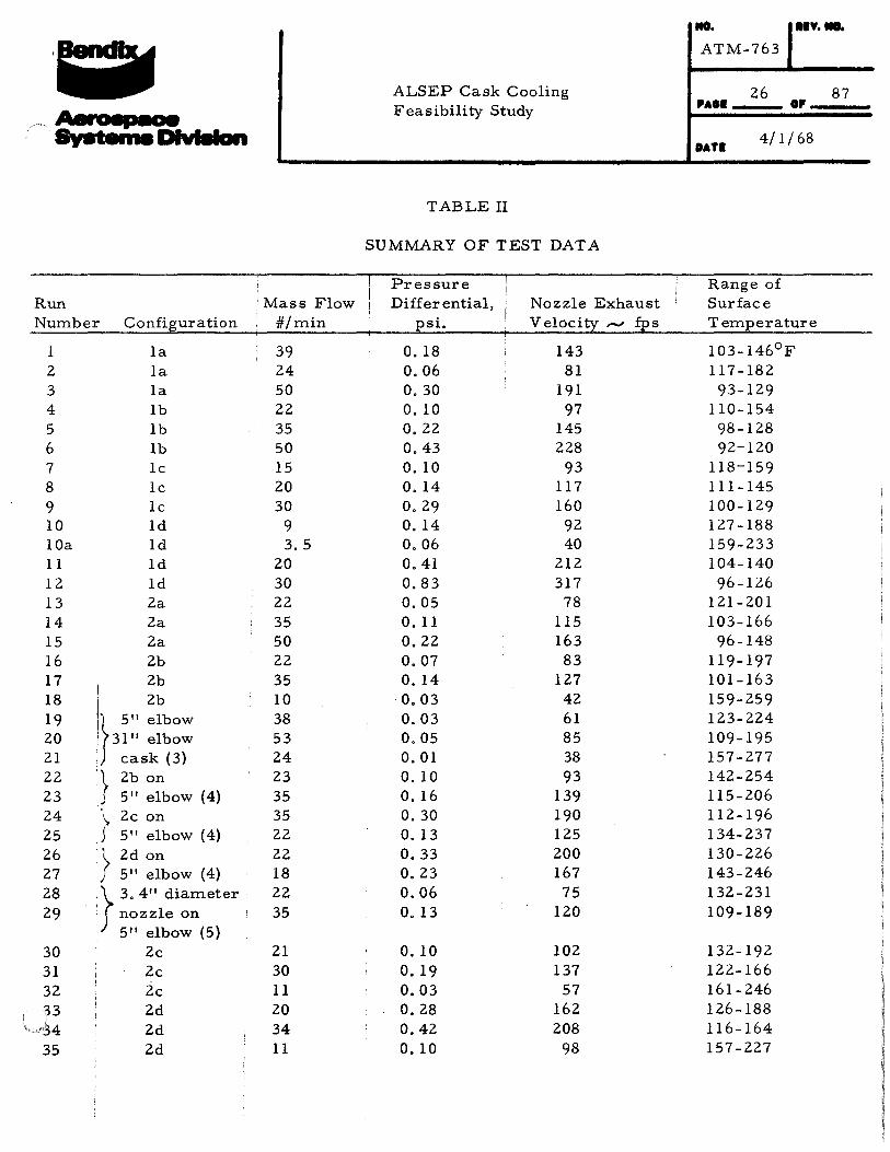
ALSEP Cask Cooling Feasibility Study
2. 4 Summary of Test Data
PAGE
DATE
The test nozzle configurations and flow conditions are given in Table I. The individual runs are tabulated in Table II with nozzle sizes given below.
Config. No.
1a 1b lc ld 2a 2b 2c 2d 7b
Nozzle Area (in2
)
8.40 7.04 5. 17 2.80 9. 16 7.80 5.92 3.56 5. 17
The individual equilibrium temperatures are listed in Table III.
25 OF 87
4/1/68
Run :Mass Flow Number Configuration #/min
1 1a 39 2 la 24 3 1a 50 4 lb 22 5 1b 35 6 lb 50 7 1c 15 8 lc 20
9 lc 30 10 1d 9 lOa 1d 3.5 11 1d 20 12 ld 30 13 2a 22 14 2a 35 15 2a 50 16 2b 22 17 2b 35 18 I 2b 10 19 \ 5" elbow 38 20 I 31" elbow 53 21 ! cask (3) 24 22 } 2b on 23 23 5" elbow (4) 35 24 - 2c on 35
J~ 25 5" elbow (4) 22 26 } 2d on 22 27 5'' elbow (4) 18 28 } 3. 4" diameter 22 29 1 nozzle on 35
· 5" elbow (5) 30 2c 21 31 2c 30 32 2c 11 33 2d 20
'~-~4 2d 34 35 2d 11
ALSEP Cask Cooling Feasibility Study
TABLE II
SUMMARY OF TEST DATA
Pressure Differential, Nozzle Exhaust
psi. Velocity ,...., fps
0. 18 143 0.06 81 0.30 191 0. 10 97 0.22 145 0.43 228 0.10 93 0. 14 117 0.29 160 0.14 92 0.06 40 o. 41 212 0.83 317 0.05 78 o. 11 115 0.22 163 0.07 83 0. 14 127 0.03 42 0.03 61 0.05 85 0.01 38 0.10 93 o. 16 139 0.30 190 0. 13 125 0.33 200 0.23 167 0.06 75 0. 13 120
0. 10 102 o. 19 137 0.03 57 0.28 162 0.42 208 0.10 98
MO. nv.-ATM-763
26 PAOI OP
87
DATI 4/l I 68
Range of Surface Temperature
103-146°F 117-182
93-129 110-154 98-128 92-120
118-159 111-145 100-129 127-188 159-233 104-140 96-126
121-201 103-166
96-148 119-197 101-163 159-259 123-224 109-195 157-277 142-254 115-206 112-196 134-237 130-226 143-246 132-231 109-189
132-192 122-166 161-246 126-188 116-164 157-227

: : . ~ Aerospace Systems Division
:Run I Mass Flow Number Configuration j #/min
36 5 11 nozzle, 14" I 43 off, cask@ (b) I
37 ~ I
21 J 2. 5 11 nozzle 1 . I 35 38 45" off cask
@ 45° (b) 39 ~ 20 11 nozzle 18
t 40 ' 45 11 off cask 24
--~ 45° (b) 41 7b 20 42 7b 10 43 7b 4.6
ALSEP Cask Cooling Feasibility Study
Pressure Differential, Nozzle Exhaust
psi. Velocity~ fps
0.04 69
o. 18 135 0.44 224
0.24 178 0.56 238
0. 19 94 0.09 63 0.02 28
NO. IIY. NO.
ATM-763
PAGE 27 OF 87
DATE 4/1/68
Range of Surface Temperature
136-222°F
136-234 114-191
129-232 111-190
113-146 131-177 177-264
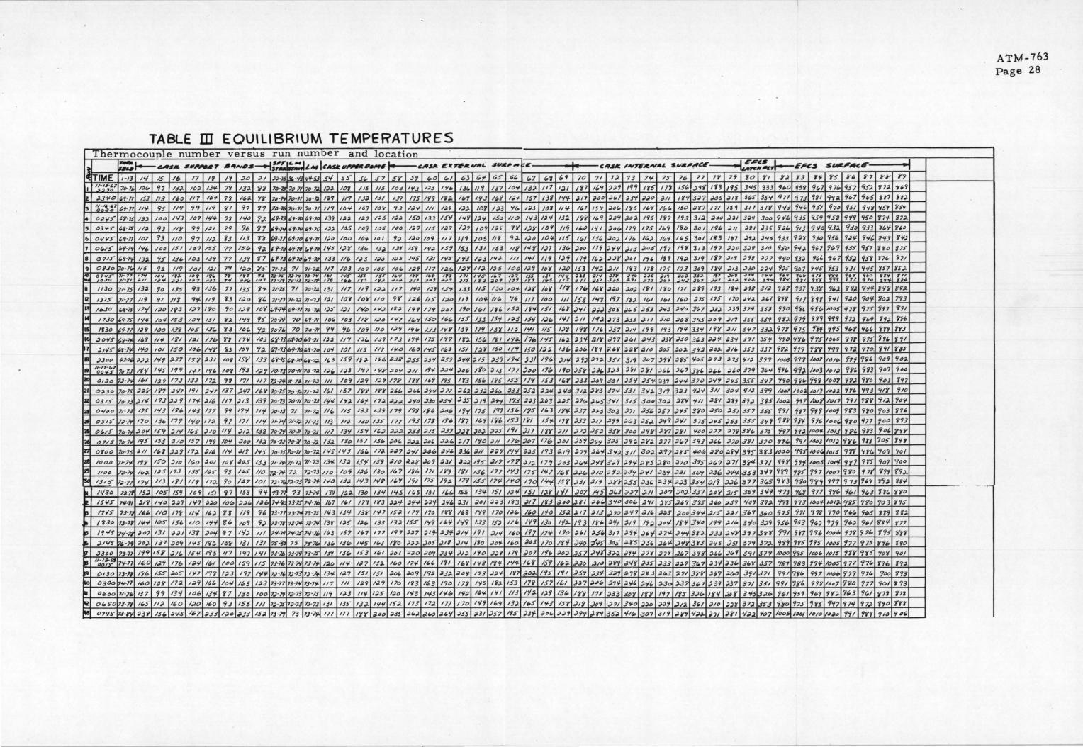
TABLE ID EOUlllBR\UM TEMPERATURES Thermocouple number versus run number and location
Ill =~--CAll& 141,.,7 6..-$---f:~tAIIICASICII"'*I-I~CA$1& Clt~le.-L 14i~IME i-13 '" IS 16 17 IV I 'I ~0 ~I .)) ·JS 10-'/J 1/lf-SJ .5'1 :,·:;- f~ 57 .5Y $'1 "Q C./ t:>J Cd
I ~~-~~~T 7D-l/. /:1{, '17 1.0. IO:J. /.:N- 7'i' 13:1. 'i1 ?D·ll ?o-71 70· 7.). ":J. IO'i /I$ /15 lt>.S lt/3 nJ I 'lib 13f. 11'1
2 ;.p,t:o """ 153 113 lj,D 117 lt.fl 7~ /(.:J. '1¥ ?#-1'r 7o-71 '" -~ 1;)7 117 /3;1. 13/ 137 /75 1'/'j 1'1;1. 1(.'1 1'13 , ~~~~-~~ ,,. 71 /l'f 95 119 'i'i 119 '(I '17 '17 711·1d 70-71 74 ·71 11'1 /0'1 /67 It>)' 'i3 1,;)¥ Ill l.)f /)). 10'1 .. 0;1.¥$" &'i'-75 133 /00 1¥3 /07 I'll' 7'1 IVO '1~ ,,.1J ,,.Jr. l.t-70 139 I:J;J. J.)l ns I.);J 150 /3.3 IS'I I <I'( /)'1
5 O:JY.:.- ,.,.,IS" 1/:J. 9.1 liS' 'H /;11 79 96 '17 9-J~ '1·7C t.f·70 1):1. ltJS 111'; lOS 11?0 1(;7 /IS /~7 1)7 IO't
6 OvYS" ,,,.,, lOT 93 //0 97 II). 13 113 n 9-71 1.1·7~ ''1· 11 I;Jo loo IO'f 10 I 9.). /;)() 109 117 1/ 'I /05
1 O(H5" /.f-7' I¥{. /00 /5"1 lo? ~~-.s 77 /5"(# 9:1. ~'1-1. t.f-70 (,'/-70 /'IS l~'t' 13(, IJ) 131 l.f'l I 'I.) IS'l 153 131
I 0715" I.N'f 13:1. '15" 131> 103 l..}'f 77 139 '17 "·13 I.'No l.'i-.:1:1 133 lib 1)3 I;Jo I~S /liS l.i'l ltl~- /'13 /;JJ
9 OP.Jo 16-lw 1/:i 'i:J. 119 /01 /;/./ 7'1 I;J.o ;y~- 71-lS 71 71· 1;1. 111 /()3 lo7 lOS /oj, l~t 117 1;/.f., /;1.1' 11:1. ovv.r ~~,:;.; 17¥ ~~-- '!f, ~~. '"' ;~ ~~
,J 7~ ·~~ ~~?,~ U· ?~ ,., ~~ IS!< ::I /6Y ~~I' , .. '"' ~~~ j~~ D-70 ~~~ '"" 1~7 ii~T ID7 , .. , ;~ - >il 111 tr~ "'"' .u ~"' o>;J• IS
II /130 li·7S /J;J. 90 JJ!i 93 /.J6 77 I.J.S Y'f 71·1S 71 71>·7~ 13/ /17_ II'/ 1.)~ 117 /'10 1;11 IJY 1.n /IS
IZ 1315" 71-17 119 91 111 'ft' 119 '13 /;I." Y' 11-n 71· "l.;f 71-?.J I.)/ IO'i IO't' 11o 'ill /01./. II~- /;lO II 'I I"~
ll li>JO t.t·7.f 17'/ 1:10 /~::J /;)7 l'i'O 'lo 1..).9 IO't '1-N 1>'1-11 14·1.- 1):) I)/ I'Y'o IY;J If.) IH 179 :Jol l'lo /{,1
If /1.10 ''H.f I'll/- lo-.1 l$.3 IO'f lSI Y:A 1'-}'j 'l:i 7() -l'f 70 ,'1·71 lot. 103 II¥ l.,).o 1'>'7 /(g'f ISO II.{, ISS IJ.J
15 lf30 ~HI /.)9 1"0 !Jf lt>S 13(, 13 '"" 'l:J. ?tJ-11. 10 7<>·71 99 'ih IO'i 110 /,;J<; l<;h 1./J ;yy I:J'I 1/'i
16 "0'15 l"v-1 II. 'I II'/- Iii I:JI 17h 'I? 17'1- ltJ.J (,'/·7 (,1-10 f.'l-11 /);). 119 /3(. I.S1 17.) l'i'l 17S 197 /~].. 15(,.
17 ;J.jflj- "t ·l~ 1'1-o 1o1 ISO 14{, I'IY 'i3 10'/ '1~ ''1-1. 1>9-7< /.'t -7 IO'f /()/ 115 //J 1¥0 li>O I'll.:.· /(,.1 IS/ /;;J'I
• )340 ~l-7, ;I.):J 1'1'1 :137 /~f ).i/ 101 15'1' 133 I.Y·7S (.F-70 .:.~- 1~ ,, j 15'1 If'- H-1> ;1.:18 .J55 ;JJY .:JS7 )'If/. ).15
" 11• 17-{,7 oo"•ir 11J·7.J If'/ l'fS 1<(9 Nl I'll. /01 193 1,)'/ 70-73 70·11 7t> ·7;1. /;J{, /;J3 /'tl IYI' ;lOY ~II 1'1'1 .)~-- :Jol. ;fo
Jill 01.10 f].)-lt / .. 1 I:H 17.] 13J 17;.. ,, 171 Ill 7.) -7" ;r-TJ. 71•7.3 Ill lo9 /:J.'I I;J'i I'll' IY'I l''i 1'1$ I'(J IS~
21 O;J.JO 7o·7S .;l;;J.f' IS'1 .:J'Il I'll .)'17 137 .Nl l''t lo-75 7o ·h. 1/ · 7.3 I(,, 157 IYY IY¥ ;/'" :lt.t. """ J7/ :If.;! ;JJ:J.
a OJ 1.$" 7o· 7.J ,)./ol 173 ,_,~'I 17'/- .)Ill /17 )13 13'/ lo -73 '10·11 7o-J.J I 'Ill I 'f). 1/.J' /7.) iJ.);l. .)'10 ,;)36 ~.S'fl JJS ;JJ'1
Zl o.,;.,o 71· 13 175 1'13 1?1. 1!13 177 'i'l 17'1 II'/ 70·7J 71 11· 7;1. II(, 1/:i /.i.J IJ'j 17'1 l'i'i IYb .;~oo I'/'/ 175
illf 0515" J:J ·lf! 170 136 17'1 1'10 17;). 97 171 Ill(' 71-ltf 71· 7;1. 71-lJ 113 1/;J. ISO /J.J- 177 1'1.3 171 If._ IY7 1.:0'1
11 0.:0;5" 1()·7<) :lOti 159 )ltl /(,:," )IO II'/ )/:J. 138 70·l'J 70·i¥ 7o ·JJ /1} 13'} IS'1 lb.) .).iJ;l. .;J,J.3 ;!.IS ,;}J7 .).Jf ;J.D:J.
0!11 07/.S 7t>-7¥ 195 /Sj ;J.to 157 I 'it Ia 'I 0/oo l.f:J 7tJ·7J 7o·ll 7o ·l). 13;;. I Yo IS/ IS'- .;o.:. ;;1..);1. :JD'
, __ .)17 19o
n OTOO lt> -15 :J/1 lt..l .);J.f 17).. .;/I~ 11'1 :J/'1 N:;· 70· 7. 7o-ll ]0 · 7;1. I'll~ 1'13 16, 17~ ;;.;n .3W ;;.;;.t:, ;Jjll. )3, Jll
zjl /000 llr7tl I'! I' ISO :Jio /t1.o :J.o:>/ /0'1 J6f I.J.J 71· 1~ 71·7j 71-73 13<,1. 13:1. IJ<I IS'/ .:JIO .:1.)¥ ~'i ;JJ/ ,;}.) 1'/!i
Z' /IOD 7.)·}~ lv;l. 1.:15 17.J 13S ;;.~- 93 ~~- 1/0 17.1-i¥ 7;1. 7)·73 //0 lo'f I.:J~ /Jo /(, 7 1¥(, Ill IY'/ IYI IS{,
" 131~- 1.) ·77 17'11 /13 IY/ 1/9 /7:J. 'lo /.;17 10/ 7J - 7. ll.7· 7J 7;;. ·}oJ 1>'0 I.S.;I. 1'/3 I'IP II. 'I l'il 17~- /f..). 179 1.5-f
.. 1'/30 1;._-n 15J IO!i IS'i It> 'I 151 '17 153 '1'f 73·1 73 7.1-l¥- 11'1- J)-.,1.. 130 13'1 l'fS "s 151 ,,(, ISS 13'1-
• ISY!i 1'1-PI jl'( l'fo :J.:J'7 l'f-7 ;1;}0 lo(, ;J:Jw 1;1" N-~ 13·7S 7<./-lb 11.7 l'-1 17'1 1V3 J;;.of "~"'- ;)J'f )'II. :J.ll -'DI
i! /7VS U·l. / .. {,. 110 17'1 /IV ".,). H 1/9 9{, 73-71 ?3· ?'1 l3· 7S 1'13 IJ"/ IJY 1'1-1 15;1. 11'1 /70 /'j"f l''i 1'(9
~ /130 7.1 -71 1¥'1 lOS IS' 1/0 l'l'f ff(, lo"f 9:;. 73·76 13·7" 1]-i¥ /3'( I:Jo /.){, 133 13). ISS" l'f'i lb'l 1'-/'i 133
~ /'I 'I~ 7'/-li ~"7 131 Jd-1 133 .;I.O'f 97 1</;J II/ 7'1-]f ?'1-l.i N -J' /(,J 157 I(,] 177 I'll J:J7 )I 'I- :J.3'f .:JI'i I'll ,. ,:1/'f/S 7/. ·lf :14.,). 137 ;;.ac; /YS /'{;}. IOi' 131 131 ?S-ill 1~ JF-7'- JJ(, I.J(p 1¥5 If./ ll'o ;1;1~ )4S ;)IV ,;)J'I /'10
p .;2340 73-71 199 IS#' )/{, 1511- l<f5 117 /97 I <;I 7J-lh U ·liJ 7J·7S IS<( I.J" 103 lwt ;/ol ;J~o .3o'1 .)3'1- ;;}J~ 1'10
~ "D~';_;-r 7'1-71 160 l.;l'i 116 1~'1 /If> I /oo 159 liS u-70 7]· ]¥ 7.1-71'- /;/.0 11'1- /.J l 13;). 1~0 17-,l II. I. 1'11 ll,'/ l'{fl
I! 01.30 73•11 l'i'- ISS )0~ 1)17 /'f'l I;J..J I'll 1'1'1- 1,} ·11. 1;1 ·13 7;) ·/~ 13/f- I;J.'j lSI 1.$1 jo(, :Jo'f /9.J. :J..J;J.. ;Joy 173
~ 0300 11-¥·71 1~0 liJY 11;J. ;;J'j /(,(, lov 1'-5 1;1.3 13-17 71·7!1 7J-7'1- liS /II I:J.~ /;/.'I 170 1'13 1"'3 1'10 171 l'fS
~ Oiloo 7/·}i> 137 99 13'-/ 106 13'1 '17 /30 /0() 1,;J· ]¥ l.)-73 7;7·/.J 11'7 /;l.j 11'1 1;1.5 1;/.0 '"'' N.J 1'1-b /'I ;I. 1.)<;-
~ or. :.-o 13· 71 1~5" II~ 160 1.;10 160 93 155 Ill l;J · :b- 1;1·13 1#·73 IJI 135" /).).. Iilii- IS:J.. 173 17;J. Ill /70 1'1'1
u 07'1:," 73-~ '-3~ 151. :J'IS 1<1.7 ;1.33 /~0 ;J.33 15;!. lJ -7'1 73 7J ·~Ill 177 l'iY )00 :J.JS ;1..:0) .;!..(.() :1.1.'1 ;155 ;1.31
$1;/e,._ ., j.. r;,f "' ~7 ''~ ~'I 70
137 10'1 JJ). 117 I;) I rn lt.i I;JY. 151 13'1 N'f )I 'I
/)3 '1~ /)3 10'1 II 'f. /(.1
15<> 110 1¥3 l-''i lj:J. I 'if /;/ ) 'I 'I I~S' 1()'1 ll'f /~()
lit 'I:J. 1).0 10'1- 1/:i 1(,1
JS3 /If "'~ 1).7 /J{, )60
IY:J. II/ 1¥1 119 /). 'j 17'(
1;;5 10() I:J.'i ID'I IU> 153
~~~ ,., ISS ~t' ~~~ n~ /Sf ,,. , J
13<> 10'/- /,;Jf /o'l /j'j lllt1
"" <jl. Ill loo Ill /53
If{. 1$;;}. IY¥ 151 11.¥ J'll
lSi I ;iS 15'1 l.)t, I'// :J.II
I .H liS 1¥1 11:r /.)3 J'lr 11 I 1';.,1.. 176 I 'IS /(,;). ;3¥ 150 ll'f /50 I;J) 13~ :J.~{,
J.1'1 1'/<1 )j/ I'/{, J.l'/ ).'~)
:Jij IJJ )110 17~ lfo ~5~
IU" ISS ll'f 15] /'" ).J3
).&(, :J.Jj :J5;J ))'rl ).till 31..).
;J.H l'i.J .);J.j )..o3 .).)5 :J-711
/'17 151. ns- 11.3 IY!f. .;/37
I 'll• 153 IYI 15'1- 17'( .;J33
.;J.)J" I'll J/7 I'IY )I/ )..1)
:J/1 llh Jo7 17b :lO/ JS'I
J:J'l 19'1 ;};)5 193 d.t9 ;; 7'1
.:1/7 ny J./;J. ll't )..63 :J.(,'f
177 IY3 11~- l'f 1 /(,f ;J~
17t< 1..0 170 l'f'f- lSi' ;l.i/
,-'17 ,.:--. IS/ 1;/ 'f l iS/ I)Y ~07
;);)J l'i3 I )./1 l/'13 ;;~a .)YI
110 /:Jt.. 1~0 /'10 l.f.;J. ).17
IS;J 11'- 1'1'1 1.3tJ If'- ;9 3
:J/1/ 1,0 lfL 17'1' 1'/0 j'-1
.JoV. /j,() )43 /10 IY'I ;)'ft>
;J,;J 'I 179 ;)Ol 111- ~;.. ;;57
1'1/f- l'fl,l. If. 'I 1.5'1 1'-:J. ,).,)o
.I) y /f7 IJ"J.. /9:i I'll )5'1
I 1:J. 15.3 17'1 151 1~1 J;17
I'll 1/j 1'/:;. 1;19 13(, IYr
n.~ 13;J. /j,..)" /'f:l /5Y .JIY
.J57 ItS ;JJ_f_ diJI.. ;;;).'! .;J.'jif.
CA.$111: -'N'F.C~A£ s.-.-,~~ -----f.r!":!!.J--E.'e~ 71 1~ 13 7'11' 75 7~ 77 7Y 7~ 'iO 'it I';J. 1'3 Yi'
l~<t ;J:J'j 1'1'1 I 'IS 17'1 /St. I.) ~'I 113 1'15 3<15 333 91.0 95'i <it,7
;JOO :J(,7 )3'f ;!;JO Jll /~¥ 3:J7 ;1.05 ;Jtj 3(,$ 35¥ 977 <j7J ~'II
tS'f )6{, l'i5 II. 'I /~{, 150 :J'O 171 If, 317 311'- 'Ns 'i'~' 951
/f."' ):J'f J6). 195 l'i7 1'13 3/:J ;/.4() )~I 3.,1'1 3oo <jtlb "iH 'iS<;
I'll )D(, 17'1 175 /(,'; 18o 311 I J9e .11/ :1.11 )35 <;;J(. 'tt.J 'iVO
13(. ;J.o;;. '" /~;I /(,'f 1r.5 301 lf/3 1~7 .11;1. )'IS 'i3:J 'f;J'r V.JO ll'i ;yt~ )13 .).o~i 1'17 Iff 3/3 l'i7 ;/;10 3.)'1 J/0 95"0 9'1;;. 'iH 1,;. :J;JI' )~I l'i' 189 /'(.). 319 1'17 ;111 )ft ;;n <(<;<> 13:J. 'f(,'
I'I:J .).II I'IJ 171 175" 173 34'1 I 't'f ,;JIJ .:JJo ;;;;y 9:JJ" '107 'i<IS
~~ ~1t' i/n ~~s .m ~~~ ~~;>. ... 1~ .... 37¥ ~ .... ... m ;~~ .3;S "'I ~7~ 3~S :>-4;J ¥~:>- .J9 "" 11.r ;);1.0 :II>) 1~1 l'io 1]1 ;lf'j 173 If 'I )11 _II,;J <;;J.t '137 B~
l<tY 197 /f;J. /(,1 II> I 1(,0 )7$ t?.f llo .J'I~ .,)." ~,y 'ill i'ff ;;) $4"5 ).t. :i :J.!iJ )'1-.3 ;1'/0 3(,7 )}) ;Jj7 37'1 3.fl 1'/0 'fj-4 'ff(,
/'f).. n3 ).JJ ;Jf7 ).10 :loft 3'1.5 .;J.ti'( ;/If 3$"5 33'1 yj'). 'lJ'i Ul
I"' )f1 :J.I'( 1'/'i 1'13 1'1¥ 3J'>' l'li' ;/.1/ 3'17 j.J.). 'i71 'iJS <;}f. Jlf J'l7 )f,l :1'13 ;JJ~ ;J.Jo 31..3 ;/.)'/- ,;JJ'f .i71 3SS' 'l'io 9'1l. f'15
l'i? ;il.t.f J:JY :lit> )65 ;16;1. 3'1;1. ;/.D:J. )I' 3.fJ 337 yy,;. '179 'iff )?;;. 351 3t9 3u7 )'/</ ;;.,-~- '145 j 7.1 ;1.7J <;1;1. .J'i'r 1003 'i'l'i /407
J3l. 3;13 Jl'l ;,, .:-1.1. :J.w1 Jrl. ;.,, :J~ 329 3f. .. 'ffl. C('f:J. /463
;J.a'i ;iOI ~5'1 .)5"' :137 ;Jy.;. ]70 :J.'i'i ;Jf/.S 355 .i¥7 9~0 LH" 'if'i -'¥.3 :17<1- ].JI 3<1;1. ]I 'I J.)J -r.N 311 .Jot,~ f/:1,1. 3'1'1 1441 /DO;). /0/]
:J.t.~ 3tll 315 .Ja.o 3o:J. J'IY "/-II .2~1 J·n s'"- 375 lt>o;;. 'Ttl /t>oS'
.);Jj 303 -'71 .;If(. J:i7 .J'I, 3¥0 .:Jso :J.57 JS7 355 'if/ yf7 'ff'l ;1./7 .;;J.'f'j :J-~3 ;JS.;.. )'l'i ;J.'II 375 .;JfiS ;J!i3 3SS .J'I'i Hr 'lf'l Yfl.
).f;l 3.]"; 3oa .J.'ir .J.Y1 )fl 'Jioo .)77 :J.7'i 31/(, 31~ - '1'17 H:J. /00'1.
.;l'fS' 3iJ5 ;;.<;;;. .;zy.;;. J77 :1(,7 3"/J ;J;.(. :JJo 3S'I 3?0 .fft. '?'II loaJ
:J.[#'f 3'1:J. -311 3o~ :J.17 :IS'S t#t!. :JS'D .lf'l 39S" 38'3 /liDO 9<f5" /()O'
;J.Sfjl .?;;.'j )'j'f .;lf-5 ;1.§"0 ~70 3~s .)(,7 ;J 71 314 .371 <i'H' '7f'l- 11>05
,}./() ,;J.'j;l.. ).S~ ~-~/ .:13'1 .;1..3/ .fl.'t ;1.3~ :J/14 353 3'17 'f'('t u> 'f't7
.;/./9 .:LI'S' JSS .;I..J' ;<J)o( ;1;)..3 ~s-¥ :JI'f J.Jb 377 3r.5 .,Y3 <J'(o '7'i";
I <iS ~f.3 ;(;;1.7 .).II )07 ;)OJ- 337 ,:10 i' ~s 35'1 3<1'1 <f7J 9t,l '171
;;."' 3¥0 dO" J.91 Ji"..l ).'9 3rs ;/~ ;;JS'I l/4'1 3'1~ '19J '1~3 /t>o'f
;J/3 .)70 d-'17 :;;;. .:J:J.S ;).o~ .J'IY. .;/1~- ,};)/ 31.9 3(,0 'i75 971 91'i
IYI> :J'f/ .:11'1 19). "~'I lf'f 3¥-o 19'1 .).I{, 3'/o 3;J.'I '151. '153 <j(,J
).5' 3J7 )'I'/- ;• 'f ;/.7Y- .J.W 3f':J- ,;)JJ ).. 'li' 3'17 Jy'i 7'11 9'17 ';'16
-:1¥$ 30~- ~f(S ).5' ;J.~Y. .J'Ii Ja-J :J<i> ;}fiJ 379 .37:1- '1'1'1 1'f> 19S
.)</( 3,;;. ;It 'I JlY )79 ,).(.7 3 'li' ~"' )(,f J"'l .379 /ooo 9~5 '""" ;)10 Ji''f .;Jo/f ).Jj' .J.J.J :J.:J.7 3t,7 ;J.3'f )3{, 31.'1' JS7 '187 '183 f"'l'l-
.;1.3'1- 3:1'1 :J-7'1 .Jr3 ;1.(,3 :J-71 JrY ,.7 ~ 3<;1 .i71 <i'll '17w 9'17 ;;.a~ :;.,'/- ;JW,. ;)'fl. :l3o ~37 .3'-7 )3'1 )37 37/ 351 '1'11 'II/I. Y'lf
17Y ;J.3J sor lfY 1'17 /fS 3.U, t¥'1 .:ll( 3'15 I.J;.(, 1•1 9S'I '16'1
~'I ;).7/ 3¥-t> ):J.O ;):J.'j .;J;;;. 3bl )10 nr 37).. .3S.J '71/0 '17-f 'itS J.t9 35~ ¥1&. .301 31'1 .).¥"1 <f.;J:~o )II J.YI '1-.:J;I Y.,7 loO!_ '""' '"10
S,_I'ACE
'i'5 i't. ~7
'i 1(, <iSl '153.
9<f;J. 'ft,7 9'-5 'iu '151 'fi'i
'151 '7'19 'i50
93). 'i3o '133 95b 'i.:J'I- 9'1t.
'ill 'j 'iS~- 951
9(,7 9.5) 95'1
'153 9JI 9¥S ~"fl '" f•o
f7J 'flO
'j(,;J. 9~J. 9'1/f
'fill f,J.O '10'1-
/045 'i7Y c;n· 9'1'1 '17J. 'ft.9
'I 'IS f{,f 9"-
IOOS 971 f(Jj 99'1 'i 7;J. 970
Ill/It> frt 1'i'
161) 'fS't. <;gJ
ilao7 97). <;ro
IIJ;);). 'ff/, 193
/t>/1 f'll fH /4Df 'Tr3 'f'iO
104, <(yo 'Ill
/01] f f'' 9tJ /01) <ir' 'lrJ
Jots '1'1'1 'rff. IOIY 'IVl '/r)
/Do? 9'i'tJ '? 7f
'197 'j 1.J ''" 'it'- t/~J '1,3 Jot]. I'9Y5 9flo
'f?O 'fl.{, 'ti-S
979 ,.;;. ""I
101?" '171 'j71t>
IOOS '177 91.5
lOIS '11't' ?'iS
/OOS '7 ll "/7(,
/(J()(t, '171 'f7w
/11117 'f'j'O '117
'IY:J. '1{.3 'f(,/
<f'f7 <fl'l 'il;J.
/4.).11 '191 '1'1'1
j'j'
'17:1.
H7
<t5t
f7'f )t,'f
·?¥1"
j'to
'(](,
1:i7
;;~ tn fO:J.
'111
1'1:;.
'if 'I
t'" '/"fl
94<f
107
'ToJ
91'1
'fl).
'foJ
'JOO
fo/,
'io!i
'Ia~
907
<f'l'l
'l"t:J..
He. '103
1f'l '1'1'1-
(95
i"fh
rov
t'f{,
'fDo
'fOI
l'i7'i 1'/0
'/10
·I I' 'I .,., H:J
~5t
'/7).
j"'o
'I'I'J.
filS"
'171
fSJ..
:;~ 8'¥.).
7<f3
ffl
rH> rn f'i/ 'OS
9o~
~60
'if7 'i/O
'to'(-
1f9' Y'l3
'1H' i'll
'to/
940
'{<;;;..
'lt'f '(YO
r~s
tr:J. 'r7J
l{fff
(fO
'iO/
19:J..
YU 7'13
'i1'i
1rr 901.
. ,
ATM-763 Page zs ·

NO. REV. NO.
: : I ATM-763
ALSEP Cask Cooling
Feasibility Study 29 87
PAGE OF
~ Systems Division DATE 4/1/68
3. 0 THEORETICAL AND EXPERIMENTAL ANALYSIS
3. 1 Background
The original intent of this section was to present the analytical design approaches and performance predictions for the various cask cooling configurations. (Figure 1. 2). However, after examining the test results, it became obvious that the functional behavior of the experimental data was not in accord with classical flow theory. Thus at this point there is little to be gained by going through rather involved analytical operations which at best do not give accurate predictions of the problem at hand. Rather these preliminary performance predictions are relegated to a discussion (Section 5. 0) of this report and it is more profitable to directly examine the data in light of classical flow theory.
Note that the above comment is not intended to indicate that the classical approach to this design analysis is in error. Instead, as will be subsequently shown, the problem seldom achieves conditions whereby the classical approach may be legitimately applied.
3. 2 Basic Open Flow Analysis
In this type of analysis it is conventional to first establish the particular external flow field around the cask, and from this data to determine the local boundary layer characteristics. For heat transfer purposes the boundary layer characteristics would include the effects of both the momentum and energy equations. However at the temperature ranges encountered in this problem, it is adequate and even desirable to simply use the Reynolds analogy to relate the local heat transfer to the local skin friction
For preliminary purposes the external flow may be essentially treated as that emanating from a free jet of suitable geometry. Then the boundary layer skin friction may be obtained through the application of local similarity considerations, i.e. , the local external velocity is assumed everywhere constant so that typical uniform velocity solutions may be used (Blasius flat plate, power law distributions, etc.).

: ; . . ALSEP Cask Cooling Feasibility Study
NO.
ATM-763
PAGE 30
REV. NO.
OF 87 Aerospace Systems Division DATE 4/1/68
The application of these fundamental solutions requires that the problem is well specified. That is, the flow in the jet and/ or the boundary layer must be either completely laminar or completely turbulent, the point of flow attachment must be well defined, etc. However when the problem is not well specified it is not entirely reasonable to anticipate reliable predictions from such an approach. For example, the transition Reynolds number for a jet is of the order of 100 as based on the nozzle conditions. When this value is exceeded the flow from a jet will become turbulent, but only after it has traveled a finite distance. Thus the flow must travel the order of 20 nozzle diameters downstream before a fully developed turbulent jet is established. This result is true to a large part, irrespective of the upstream flow conditions. Consequently the initial portion of the external flow on the cylinder as in configuration 1, can not properly be considered either laminar or turbulent. Further since the velocity decay rate is different for a two-dimensional laminar and turbulent jet, it is not clear just what external velocity distribution should be predicted in that region.
A similar problem exists in the boundary layer where again a finite distance is required for a turbulent boundary layer to develop. Also the problem exists that there is a minimum surface Reynolds number to generate and maintain a turbulent boundary layer. Thus even if the outer jet flow is turbulent, it is not necessarily true that the adjoining boundary layer will be turbulent. However in such a situation the corresponding heat transfer in this pseudo laminar boundary layer will be greater than that of an undisturbed laminar boundary layer. Thus from these above comments, as well as others which will be forthcoming, it is apparent that the flow patterns of the various cask cooling configurations seldom achieve a definity of character which would allow a relatively simple type of classical analysis.
Consequently in the almost total absence of any theories for transitional types of flow, it is perhaps more enlightening to look at the evidence, i.e., experimental results, and then trace this information backwards in order to ascertain the particular character of the flow.

. -. -NO.
ATM-763
PAGE 31
REV. NO.
OF 87 Aerospace Systems Division
ALSEP Cask Cooling Feasibility Study
DATE 4/1/68
For the velocities and temperatures encountered in this experiment, the air may be considered to be an incompressible, perfect gas. If for the moment, the external flow patterns of each cooling configuration are considered to be representative of free jets, then the theoretical velocity decay downstream of the nozzle will be proportional to:
Laminar Turbulent
Two-dimensional Jet x-1/ 2
Circular Jet
where X is the downstream distance.
Thus for each cooling configuration it might be anticipated that the rate of change of centerline velocity with distance would at least be asymptotic to the proper values in the above table. In Figures 3. 1 and 3. 2, plots of maximum velocity versus downstream distance are given. Although definite slopes are in evidence in these figures, they are not in agreement with those of the above table. This lack of agreement may be traced largely to two basic sources. First the tabular values are for fully developed flows and these do not occur until the jet, whether laminar or turbulent, has proceeded the order of ten or twenty nozzle diameters downstream - thus it should not necessarily be expected that the initial portion of the flow will follow the classical decay rate. Secondly, the surface of the cask represents a constriction to the otherwise free expansion of the jet - thus the velocity decay rate will be altered by this effect. Also note that the finite transition distance between laminar and turbulent flow will introduce a gradual slope change - at least in the twodimensional jet.
In all the configurations tested, the nozzle Reynolds numbers exceeded the critical value so that each jet eventually became turbulent. For two-dimensional jets, this transition region is quite easy to locate as in Figures 10 and 11. Upstream of this region the flow has some of the characteristics of a laminar jet, but it is basically undeveloped in terms of classical jet flow. Therefore, it is not to be expected that the laminar jet form would be followed - even if the inherent jet instability has not grown to a significant level to develop into turbulence.

0 -"' . ., o_.
uu o:>-
u"U -"'N ~:x ~diN -.I a: .. <"!!)"-
0~ ..1>:
]111f
Q
8
7
. 6
5 .
~ ~
.fi
?
1.5
lliliO 9
8
7
6
fi
4
3
2.5
?
1.5
1
UJ
r·n.
. !
I
' '
I
' I
1.5 2 2.5 3
., 1-' _,_,_ ;~~_.;_
:
. H: r-,-: ' ' '·'
I
,,
I
,,
• "-'
; ; ~-
'
'
' I
I i
'· 4 5 6 7 8 9 .11.0 l 1.5
'
; r:n~li;o!"¥
++ ''T";·· :.:l:·i '"~''"-'-'+" ·;
: ..
·~~ i-1 -~"•i" ' -::;:; :rB:'
:::-:;-_t:J:
i+T-+'
'
,, : !
I ' I
'i ~ ; :=~- : i'
: lT
ATM-763 Page 32
i':~f:f===E= ~ ~-
~·:•-f:c:::: l::a [;";:i'':· ' 1-:-· ;~: , .. ., ~ J-'·-; t:~ . ·•'t-·+--.~t~-- .. ,. 1": . .::. Fi~
~N 1-'
; .. f IY I :~c:c - -~ 1~-
- ~-t= . ·:": ~·" - ----::L-=::.:: ~-:_: ~:: ~=:. ---~·'":: .. ··\-==--=!==~:.: 1=-= --~~:J:::. i- --t:=~= i .
·:~:~ -~;: ; ;:;-- . ,.::: ,::: - ~:::~ 1·-
:;;:=·::k:L ~tpr- ~~--c::J I ,;.j{:: I ; :: : ; ~='===: '-~
:~ F' ~~:,:;I :. ~- !:'~:::::': :;: h.·~-'"_; ~~ fi:-._c, . ·; :c
:~.
~fll±If 1\tr ti=fil :-+::::r=-- ~~~ I;;~ ~;:±t~ t: 4:1~~ ~= __
f ~·: . i'' IH ~::: '1=: _1::: I :~: ,.:: ' ;:; 1.,,1·:-:::i[.C -- !:~ ''
' . . .. '·s:m:~: •~: -~- .
:L ":\'±-,· .. -~ . . '
:!-L. .,.:, .. ... ........ ---
I• I J;
.:=:::=:=: : ,::: ·~
:
; ~ .. , "' ~:-;::;:
·.
-"
-:·: .,
'
f'~::: = L-::oo '-='=
1:::~-J=:::~ ,~=: [-::r "
·'·:~ :~ifF
'WI· ~--=~:: :·.:::· j·--:1:--\-L-1~ • +-==~-= 1:::.::. t:.-:...:j::_
::tt;nt''' i~' ;; t~-:-+--c ~', .:t::·:
.. ·:·-
i' ~ :
~::
·:
::· .l
: -~--
' ,,
" ' ' '
I ' I
; ' '
~i I ,, !I I I ; ;
2 2.5 3 4 5 6 7 8 9 IJ.
EFFECTIVE SURFACE DISTANC~ X+ X -FEET 0
Figure 3. 1

0 --a, II) (I)
p'nn Q
7 . u ~
6
f./) -5
E-t ~ 4
l l::l
< -~ .!\
u 0 ? ...:l ~ > f-!1.5
~ 1--:l
11ll" ~
Q
A
7
~
!\
., ..
.J 4 u >-u
"' >< N
~
'.5
?
1.5
1 u,
:
I
i I
' ' 1.5 2 2.5
:
'
4 5
''" ,,
•-::::: ;-,;:,
I - --::'fc ::
=ii !l;;;o:;;;:
t ---~ _, '"-- '- =:::::~cf·- --~~Is.~----- ----'---"=--· 1--~--~~.;.:;.:__, ____ -·---: .. '
ATM-763 Page 33
, ___
---+:-·~-c---' '
-..:-::: •.:::c;:c,~::; ... l:::l----~,---j:.:: - _: , __ ~::::j:::J·
1-:· ;-: . .;-:;_; ""'·=-l-:;;c ..;_:--, -l--':l
. '' CE -;_m: •c.;: --,::- -" :o-_:_:
: _:_: ·.c:c . :: . . C:FS: .. O:.f'::.-,'
~-
::c.· ,-::-c:r=:c-.::--'-ie;_:.: t:=": ;•-' '::::-T"---- :-fc~-
:'j;;; f-A. '"I=¥ IF: t=:_-., ~=== ~==
>ii.:i"l ~-2:=c'l: · -:_:: I .. 1--- __ 1--f- --- ---- _:::_
=~
::
--=-1--
:· -:·:=F-=-=-' , 'c 1-:------i+-.-- [::'t~-.3~ :: __ 1-:--:::::. : :: I - - I= L::c : __ --;-_;:t;_~~-t=.=:::,_,_ ---+ _____ _;__,_ . _ :·:: F-'·:::::1---- !:·::::,.:_ --- 1-- _·:::_ --- 1:--: , - -- ---~--- ----r-----' ----~:;" :;:0;:; ;:::_,--1--- -1--: ,::~:IT 1-- -,::: l=r: 1 ::- -:::: f -
-----= ' - ·:::: : . ----1--'-:C-f--'-:-h '
!==- c·=::c ,:=_-.{
::: tH 1'-" : ;::___--:;:;::-: F=:: t:-::
----
-'
'' I -
: " " ' ' '' ,, ,,
' I I ' ' ' ,_
,, ''
:'
'
::': : ::=~: ·-:_ == :'- !--c ------ --- Icc.:::
·---'t-· . - -- -t ':T..:::·, __ -.. li'-: :_fj t::::i--' ~;-: ___ . -- --
-- I,_ . --- -- ,: __ :._ :_=:, .. ,.,1-:-- ~~ I:': ;J--~ ~---- I:: . I== 1-_:::
'' ' 1-----:: ~::: F:-:=
F:·::. '--"
l=:=d~ t:::-.:: t::·:-
'" p---;;:£r~:- . ::: I =_ 1:::·.- t--·-: --=-
::::F===: -· - tr: t=·:r--:·t----- ·::: 1--:: f=-:~
' :-'-HI'-F : 1-'_:_ =.j;:j_;:j;~~~;;u H~f-;1-'--', '-'-- _:_-- --
' , If-' H-;-:'j:-: __ 1----'-l-t, , -- - ::
'' ' ;: ''+' l::T '-f;St~+,~l~;++ H n+>-- ~i-~ ~~ ' HL+~:r,~: , . ~=R~~I ~~~~'-
, .... I ----'I : ,
,~,
' i : I ':·: 1-~~~'~b:: H t ,-:_:~. --I ;Tll- --- 1=- -;:' I'
I: I c-- I ~ - :: '-i 1----' - ' ,,
' -----
' 6 7 8 9liJ) c 1.5 2 2.5 3 ~ 5 6 7 8 9 114!
EFFECTIVE DISTANCE FROM NOZZLE, x + X-0
FEET
Figure 3. 2

NO. REV. NO.
ATM-763
ALSEP Cask Cooling Feasibility Study
34 87 PAGE OF
Aerospace Systems Division DATE 4/1/68
The net result of the above deviations from theory is that it is easier to look for an empirical data correlation rather than to attempt to reproduce the experimental results with modifications to existing theory. Such an approach is quite justifiable in the case of turbulent jet flows since in the absence of a reliable turbulent transport theory, it is the observed rate of jet spreading which has led to the accepted velocity decay rates. On the other hand, at least until flow impingement on the cask, the circular jet will behave as theoretically predicted since the laminar and turbulent velocity decay rates are the same.
Assuming that the external flow velocities are now available, it is next necessary to establish the boundary layer characteristics and thereby the shear and heat transfer at the cask surface. For a perfect, incompressible gas, the Reynolds analogy may be written
St = 1 2/3
Therefore the film coefficient, h, will be
or
h = Q -A-~.-.-T- =
h = ~ g u cP
p 2/3 r
St!" guCp f:l TA A6,T
By considering each segment of the cask to be essentially a flat plate, the skin friction may be related to a local Reynolds number. However the main difficulty is in establishing a reference distance upon which to base this local Reynolds number. For configuration 1 this orientation is no problem, but for the detached nozzles, the effective initial point of flow contact is not obvious. In order to temporarily bypass this problem it is possible to make direct use of the experimental data and thereby determine the sensitivity of the film coefficient to the effective point of flow attachment.

: ; . ~ ALSEP Cask Cooling Feasibility Study
NO.
ATM-763
PAGE 35
REV. NO.
OF 87 Aerospace Systems Division DATE 4/ll 68
For laminar flow on a flat plate the skin friction is proportional to Re -1 I 2 and for fully developed turbulent flow on a flat plate the skin friction is ~pproximately proportional to Re -1 I 5. For each location on the cask at each flow configuration, the effective sur1ace distance is approximately constant so that
) -112 Cfl 2 Lam .,.._. u
In addition at each location on the cask the source heat per unit area (QI A) is essentially fixed. Thus the film coefficient will be inversely proportional to the difference between the wall temperature and the free stream temperature,
i.e. '
h I""J 1
T
Consequently for each station and configuration we may write
{U t::J. T = const. (laminar flow)
uO· 8 !:::::., T = const. (turbulent flow)
Upon plotting the experimental values of u and f::J. T for various thermocouple locations on the cask, it is somewhat surprising to find that on log-log paper the entire set of primary test data can nearly be correlated with one straight line (Figures 3. 3, 3. 4, 3. 5). (Note that the term primary is here applied to the non-interferred portion of the cask surface, i.e., the front side. This is the only portion of the data where some direct correlation can be anticipated a priori.) However the slope of this experimental c1,1rve follows neither the laminar nor the turbulent value.

1{)
!I
R
6
~4
... ;::: ~=: -~:: '-
1.5 2
: I .~•+it'7 .. ~:. -~ . iit:o
:' .J''
II
2.5 3 I
TEMPERATURE DIFFERENTIAL, 6T -°F
Figure 3. 3
i .;.
4
ATM-763
Page 36
lc·'
·:=:1·-:·1 .. :~
' I'
'
..
--·:: ... :"
·c-·1: -:
·-:
''" : cjh
,.,
~;! =.~
:: -lr:-:-: ' _ ,
1;.,,: li1t +t+~~~Fi iOO 6 8 9 10

0
a, Ill (I') .,
•W O.J uu o:>
uwu -"'N ~~>< E~~ a:w ¢"Cl"-0~ .J><
1.5 2 3 4 6 8 9 0 1.5 2 2.5
0 TEMPERATURE DIFFERENTIAL, AT- F
Figure 3.4
ATM-763 Page 37
I I I I
ti• I
8 9 10

I'' Q
R
7
6
li.
·~~_ u f.il U) -
0 --a, II) (I) .,
·W O.J ou o:>-
o"'U -"'"' ~~X ~ .... -.J O:w <"e~"-oi;l ..J><
• "l
.5
')
.5
ltli'l
Q
R
7
" 1\
..
~
2"
?
1.5
1?.
' >-c--: F"-'
:
:
I
,, '
' ' 1.5 2 2.5 3
'
' '
,. I
I I
''
'
'' I I'
' I
: ' ili I
' I I
Lr:: ,_
I
4 5 6 7 8 9 ij( 1.5 2.5 3
0 TEMPERATURE DIFFERENTIAL, AT...._ F
Figure 3. 5
:
'
ATM-763
Page 38
•' '
- .. , '~
' i c:::. t~::~ •:,_1_''
I'~'" ,, __ , c=
(::- f-·--'+1----1--'-" l:c_-~
; .:d--h--· ·•: -C, ; -;,~H-'
~~---h-'' --,--" ,,, I I II
hew --c: '
1!, ' " I'
! ,, I
,. II· 'I '
c·::::; r:=:=;::;. ~---
+ ,. __
: -4•--
' " ,, •I:
::::-:c·_; ·'
.,c:;<.::: ·~ ' -~---
;+:;II: r::;: ~~.:::-1:~::~~ .:.::' -:-::· ---1_-,.c:::; --- -~-- -~
1'' ~tH: I;~,::·- L~ l~:H ~.i1 + I ~~OJ .i:: :I :::~1 : 1~1 ~--i:
-~: ' 1tiE~j~ I:;: 1''· -•. - '--,·t-~
• 1~ f;,I:ILt:.c __ . . . . :: --•·1---IJ_:..:_ ---: ' 'i~
[:j! 4 •00 6 7 8 9 1()

NO. REV. NO . . . : . ATM-763
ALSEP Cask Cooling Feasibility Study
PAGE 39 OF
87
~ Systems Division DATE 4/1 I 68
Irrespective of the slope of surface velocity versus 6. T, some streamwise variation in the proportionality between the velocity and temperature increment might be anticipated. However only in the case of the attached nozzle (configuration #I) is any such dependence evident. This particular case most nearly approximates the boundary layer flow along a flat plate (with an adverse pressure gradient) where a flow initiation point was well defined.
Since the streamwise boundary layer dependence decreases with increasing streamwise distance, the detached nozzle flows, which all the others are, have evidently become attached far enough upstream in relation to the placement of the three surface thermocouples on the cask cylinder (T-68, T-64, and T-60) to effectively reduce the streamwise boundary layer dependence to a negligible level. This is not to say that the boundary layer characteristics are not changing as the flow proceeds downstream, but that the cumulative effects of an external velocity decay and a lag in the adjustment to local similarity in the cask cylinder have resulted in a shear coefficient (or Stanton number) which is essentially independent of streamwise distance. Such behavior is in contrast to the classical skin friction dependence noted above where a constant external velocity is assumed throughout to develop such theories.
Note that none of the above comments include the fully shrouded case (configuration 7) which requires a separate form of analysis.
Since a correlation now exists between the velocity and the temperature differential on the open side of the cask, it is possible to combine this correlation with the previously established correlation of velocity and upstream flow conditions parameters to yield a relation between the air supply parameters and the surface temperature rise. In addition it is somewhat fortuitous that the maximum measured surface temperature, which occurs at T-61, is always within several degrees of being lOo/o higher than the temperature at T-60, which is one of the correlated values. Thus a correlation between the air supply conditions and the maximum surface temperature is relatively easy to establish. For the attached nozzle (configuration 1) there should be some streamwise dependence of 6 T other than what is obtained from the basic external velocity decay. However the data scatter exceeds whatever variation might be predicted so that in the interest of overall simplicity, it is accepted that all the experimental data of configurations 1 through 6 essentially obeys the relation:
1 6,T
= 9. 5 x Io- 4
Note that this slope (0. 71) lies between the aforementioned laminar and turbulent values (0. 5 and 0. 8).

: ; . ~ ALSEP Cask Cooling Feasibility Study
NO.
ATM-763
PAGE 40
REV. NO.
OF 87
Aerospace Systems Division DATE 4/1/68
Although all the attached and plugged nozzles (configurations 1, 2, and 4) essentially generate two-dimensional jets at the onset of the flow, only when the nozzle is relatively close to the cask is the basic characteristic of this flow preserved. That is, as these nozzles are placed further from the cask, the expanding two-dimensional jets eventually merge because of their circular placement. Thus their velocity decay (which is directly related to the jet expansion area through the momentum equation) changes its form as the flow loses its two-dimensional characteristics.
Consequently it is not possible to conveniently apply a single velocity decay formula to the plugged nozzle. Initially an attempt was made to find a modified velocity decay versus downstream distance through logarithmic plots. However this slope is also a function of the ficticious source point in the nozzle. After a considerable amount of data manipulation, it appeared that the best compromise would be to use the basic axisymmetric form, but with a different value of the empirical constant which necessarily appears in all turbulent flow formulations (Figures 3. 6, 3. 7). This formulation is reasonably adequate for the attached nozzle as well, so that all the velocity distributions may be expressed in basically the same form.
Note that in the above commentary no mention is made of the velocity distribution across the jet. However in essentially all the cases, the maximum velocity occurred in close enough proximity to the cask wall so that the center line velocity effectively approximates the edge velocity of the boundary layer along the cask wall. Also no consideration is given to the blockage of the flow by the cask itself. Because of the relative size of the cask and jet dimensions, it might be expected that this effect would be significant. However the fact that the experimental correlation is adequate is justification enough for neglecting the presence of the cask in calculating the streamwise velocity distribution.
Consequently the inviscid flow adjacent to the cask and emanating from an axially aligned two-dimensional jet may be written

~t\) (I()
Q
8
7
. 6 u
J:il U) 5 -. E-i
"-~ l
l;j , ft
:>-t E-i 2,1\ 1-1
u 0 2 ...:! J:il > E-i 1.5
J:il I-)
,.~
!I
" 7
0< .,
-ll
-" m~ 1\ II)• (I)~
.!JI . .., 0...1 .. uu ">
u"'u -!liN :E:x E~N ,
I a: .. <(14
CJ"-?.1\ 0~
.J><
w f ?
1.5
1 OJ
I
1.5 2
: '
' ' I
' ! i , 1 I
2.5 3 4 5 6 7 8 9 11,0 0 1.5
EFFECTIVE SURFACE DISTANCE, x + x - FEET 0
Figure 3. 6
ATM-763
Page 41
' ' ' ,.
l~_,,r l2 ';:;. ~-- ··.,.
t'f .:.: .... [.:..:: : I~ :· .. •---~-·
- .. :.:
, .. :.-.: .. f:_:_·_ . -~-==- ::::!-~: ~-··~ .
F-·
:C.CfC':c·
r·:--:~ . . ::: ..
i+-- .. :_,. 1-·-, 1-··
--~-
! .....
'irr 1:::-::
I I 1: 1:
I ,, ' 6 1 a 9HO.

1
8
6 . u ~ 5 tf) ....._
f:-1 ~ 1
J::l ft
:;>-t2 f:-1 1-i
u 0 ...:l ~ :>1.5
f:-1 ~ 1-:l
o• -I(: -~ m~ II)• (I)~
•m ... O.J uu <t>-
u"'u -"'"' ~~)( ~ .... -.J II: OJ <"-e>'" 0~ .J><
~
1.5 2 2.5 3
ATM-763
Page 42
''
4 5
EFFECTIVE SURFACE DISTANC~ x+ x- FEET 0
Figure 3. 7
,I I I Iii 1li
I
I I
6

NO. REV. NO.
: ; . ~ ATM-763
where from the basic form
u{;, =
r-
3 871
ALSEP Cask Cooling Feasibility Study
K K= u 2 dA ex
PAGE
DATE
E-: = 0. 043 v K instead of 0. 016 / K as in the classical circular jet. Upon combining this result with the above temperature - velocity correlation, the temperature differential becomes
r·- ' 0.71 - pl/4 T = 62 x+ 1.9 ·' rn/
,.---;- pl/ 4 I ·j m ' i
' I
l._ .. J where
rn = mass flow ,...._., 1 b/ sec
[j, p = pressure differential ""'-' psf
x = distance from the nozzle to a point on the cask cylinder r--' ft.
This equation is plotted in Figures 2. 2, 2. 3, and 2. 4 for a realistic range of the involved parameters. Note that this temperature differential represents
43 OF
4/1/68
that of the open side of the cask. Therefore the maximum cask wall temperature will be approximately lOo/o higher than the absolute value of the wall temperature at maximum x of the cask cylinder. Also note that the apparent wide discrepancy between this correlation and several of the experimental runs is largely a result of the partial misalignment of the plugged nozzle relative to the cask. Thus especially at the lower mass flows and pressures, nozzle alignment is an important factor.
87

NO. REV. NO.
: : I ~ ATM-763
ALSEP Cask Cooling Feasibility Study
PAGE 44 OF 87
···········===-Division DATE
For the circular jets, (configurations 3, 4, and 6) a similar approach gives a velocity distribution as:
77 cos g DPl/4 vm u = e
(in x+ 2. 7
6pl/4
where in this situation, g is the angle between the jet axis and the cask axis
4/l/68
{0 :.; g < 45°). Except for the angular correlation, this form is in agreement with the classical laminar and/ or turbulent distribution. Upon combining this form with the temperature - velocity correlation, the cask temperature differential for circular jet cooling on the front side of the cask becomes (Figures 2. 5, 2. 6, and 2. 7)
r-·-2. 7 v m.
--, 0. 71
DT = 48 L'~pl/4
/"\ /\ 1 I 4 .r--:-"'~P ym ,
.J
where
m = mass flow..........., #/sec
LP = pressure differential;--/ psf
g = angle between nozzle axis and cask axis (O .::-: g ~-~ 45°)
x = actual distance between nozzle and front side cask surface point.
Again the maximum cask surface temperatures occur on the sides of the cask and are approximately 10% higher than the absolute temperatures of the open side. Note that it is precisely the presence of the radiation heat shield which directs the flow up the back side of the cask when the nozzle is off center with respect to the cask axis. Under this situation the back side temperatures are at least as low as the front temperatures. However removal of the radiation shield would completely disrupt this back side cooling.

. • : I
ALSEP Cask Cooling Feasibility Study
NO.
ATM-763
PAGE 45
REV. NO •
OF 87
DATE 4/1/68
3. 3 Correlation of Open Flow to Theory
From the standpoint of future analysis as well as academic interest, it is useful to compare the effective skin friction coefficient as obtained through the above data correlation with that of the skin friction predicted through classical boundary layer theory. Since the above correlation essentially bypassed the need for film coefficients and internal thermal analysis, no effective surface area was established. However for purposes of comparison, a projected geometric area and a uniform internal heat source should provide adequate estimates of the actual values. As noted above, by the Reynolds analogy, the skin friction coefficient may be written as:
p 2/3 r
f'g u c p
h
Also by the cask wall data correlation
1
6T = 9. 5 x 10- 4 ue 0
· 71
Combining these equations yields
9.5 X 10- 4 p 2/3 r
n C A 0. 29 r- g p U
Q
= Q
,..CguC uTA p
The net heat output is 1500 watts or l. 4 BTU/ sec and the effective area of this cask is of the order of
A..-J 71x 8
IT X 20 T2 = 3. 5 sq. ft.

NO. REV. NO.
: ; . ~ ATM-763
46 ALSEP Cask Cooling Feasibility Study PAGE OF
DATE 4/1/68
Using these values of Q and A plus an air Prandtl number of 0. 71, the skin friction ~oefficient becomes
cf/2 = 0.0165
0.29 u
e
Because of a lack of dependence upon streamwise distance in the data correlation for 6. T, it is necessary to assume some effective surface distance if the above skin friction coefficient is to be compared to the classical values which are functions of Reynolds number, i.e.,
i
\ ·~;
\
Since the exponent of ue is 0. 29, the Reynolds number and thus X will be raised to this power. In reality X varies from approximately 0. 5 to 3. 0, but upon raising this to the 0. 29 power, this is only a variation from 0. 8 to 1. 3 or a factor of +30%. This variation at least allows a rough comparison with the classical values of C£1 2 . Using a nominal value of 1. 5 for X, the experimental skin friction coefficient becomes
0.23
In the table below this form compared with the accepted flat plate turbulent values. (Note that the Stanton number:::::::: 1. 25 Cf/ 2}.
3 cf/ 2 X 10 >Exp.
8. 1
4.2
2. 1
3. 8 ( 2. 1 Lam. }
2.3
. 1. 4
87
: ; I ~
ALSEP Cask Cooling Feasibility Study
NO.
ATM-763
47 PAGE
REV. NO.
87 OF
DATE 4/1/68
As can be seen, the projected experimental values of Cf/ 2 exceed the pure flat plate values by more than the uncertainty in X. Further if some X variation with Reynolds number had been allowed in these projected values of cf
12,
then the disparity would be greater. Although the cask surface is quite rough, subsequent calculations indicated that this condition would at most result in a small increase in the skin friction at the lower Reynolds number. Therefore the observed skin friction increases are probably attributable to the high level of free stream turbulence and the lag in boundary level development.
With respect to the lag in boundary layer development, there are two contrasting factors which result in a seemingly anomalous behavior of the boundary layer. However upon looking more closely at the boundary layer structure, the results are seen to be plausible and even expected. For a typical laminar boundary layer on a flat plate, there is a certain similarity at the various streamwise locations. That is; the individual boundary layer profiles may all be reduced to the same profile by an appropriate choice of scale factors. However when there is turbulence in the free stream, the momentum transfer to the external portion of the laminar boundary layer from the free stream is considerably increased. Therefore the effective laminar boundary layer is much thinner, than as predicted by the similarity solutions - which results in a higher velocity gradient near the wall and thus a much higher value .of skin friction. Such a situation exists in the region of flow attachment on the cask where the Reynolds number is initially low and even after reaching the transition level, there is a finite distance required to achieve transition. A similar situation, though to a lesser extent, exists with the turbulent boundary layers. That is, the free stream turbulence has somewhat of a thinning effect upon even a turbulent boundary layer where ordinarily the turbulence level decreases in the outer portions of the boundary layer. Thus the distribution and magnitude of the disagreement between classical and present experimental skin friction coefficients is relatively easily explained by the fact that all the jet flows tested were themselves turbulent - thereby resulting in a high level of free stream turbulence.
However there still exists the problem of the lack of streamwise dependence of the skin friction. At first glance this independence might appear to be the result of an excessive lag in the boundary layer development so that the streamwise position has little effect upon. the wall shear. The alternative to this viewpoint is that the high level of turbulence throughout the boundary layer results in a very rapid adjustment of the boundary layer. Thus the boundary layer behaves similarly to the fully developed flow between parallel walls; where the distance between the walls is the characteristic distance. Owing to the high level of turbulence in the outer flow (and the resultant increased wall

: ; I ~
ALSEP Cask Cooling Feasibility Study
NO.
ATM-763
PAGE 48
REV. NO.
OF 87
Aerospace Systems Division DATE 4/1/68
shear) it appears that the second viewpoint is the valid one. Therefore the lack of streamwise shear dependence would indicate that there are compensating effects which result in an almost negligible change in the effective boundary layer thickness - or more properly, the momentum thickness of the boundary layer is essentially independent of the streamwise position. These compensating effects are probably located in the rate of growth of the turbulent intensity, both within and without of the boundary layer. That is, especially in the situation where the nozzle and cask are relatively close and thus a greater streamwise variation would be expected, the normal time (or streamwise) delay in the development of the turbulent intensity in both the free stream and the boundary layer results in increasing transport across the boundary layer as the flow proceeds downstream - thereby resulting in a negligible change in the boundary layer momentum thickness and thus a negligible change in wall shear as a function of position, i. e. ,
dO = dx + d* u
du dx
·Note however that there is a wall shear drop resulting from the streamwise decay of the external velocity.
3. 4 Shroud Analysis
The experimental values of the heat transfer for the shrouded case also exceed the theoretical predictions by a considerable amount. The theoretical analysis, as presented in the appendix, was based on a smooth walled, fully developed channel flow. Sine e the geometry of the shroud rather faithfully represents a channel flow system, the differences in the heat transfer between theory and experiment must be represented by the conditions imposed upon the two-dimensional flow, i.e., the smooth wall, the fully developed flow, and possibly the form of the Reynolds analogy.
While the degree of roughness of the cask wall was not significant in increasing the shear of the relatively thick open flow boundary layers, the same roughness can be significant in a shrouded system where the boundary layer growth is constrained. Although the surface roughness of the test cask was far from uniform, the average roughness appears to be of the order of one mil. Thus the ratio of the channel height to the roughness height is of the order·of 200. For the Reynolds numbers of the shroud experiments (3, 000 - 10, 000) , it does not appear that such a roughness ratio would contribute

: ; . ~ ALSEP Cask Cooling Feasibility Study
NO.
ATM-763
PAGE 49
REV. NO.
OF 87
DATE 4/1/68
more than a 10% increase to the wall shear. However these estimates are based upon pipe flow results since there is very little experimental data for roughness in two-dimensional flow. Therefore because the flow conditions are in a region of high sensitivity to roughness, it is possible that the projected value of a 10% increase in wall shear could be either markedly high or low. Also note that some of the rougher local areas on the cask wall would result in a higher local shear.
In well controlled experiments, it is usually nee es sary for a flow to travel at least 50 inlet dimensions downstream before fully developed channel flow is achieved, {either laminar or turbulent). Up to that point the wall velocity gradients are much higher because the center portion of the flow has not yet adjusted to the wall shear effects. Consequently it is to be expected that the experimental film coefficients would exceed the predicted values over at least the majority of the cask cylinder. The Reynolds numbers for the three test runs were all sufficiently large to maintain turbulent channel flow so it appears that the shroud flow is going in that direction. In the table below, the Reynolds numbers, the predicted film coefficients, and the measured film coefficients are given for the three shrouded flow tests.
41 10,800 16. 29. 26. 20.
42 7' 400 12. 21. 18. 14.
43 3, 200 6. 6 11. 9. 7.6
Note that the decrease in the measured values of has the flow proceeds downstream is not entirely a result of the gradual development of the channel flow. There is also the factor of (1 - T eiTw) which represents the decrease in heat transfer resulting from the increase in air temperature. As may be seen in the preliminary shroud design in the appendix, this factor can represent a significant reduction in heat transfer - especially in the case of low mass flows and thus low total heat capacity of the cooling air.
Since there is little valid data and no complete theory for turbulent flow, it is not possible to apportion the relative importance of the factors which effectively increased the film coefficients in the shrouded flow tests. While it might·appear that a lag in the development of the channel flow was the major contributor (as opposed to the surface roughness), the accuracy of the applied form of the Reynolds analogy in such a flow is certainly subject to question.

NO. REV. NO.
: ; I ~ ATM-763
ALSEP Cask Cooling Feasibility Study
PAGE 50 OF
Aerospace Systems Division DATE 4/1 I 68
However in light of the success of the open flow cooling systems, there does not appear to be any point in attempting to generate a valid and plausible means to predict the actual heat transfer which is attained from the more cumbersome shroud system.
4. 0 THERMAL CORRELATION
Although a thermal analysis was not used (or necessary) in the correlation of the experimental data, several analyses were carried out to verify that the experimentally derived film coefficients were compatible with the measured cask temperatures. The basic model for the thermal analysis employs a finite difference approach wherein the physical configuration is subdivided into discrete finite elements - each of which is assumed to be isothermal. The mass of each element is assumed to be concentrated at its geometric center and is termed a node. These nodes have arbitrary individual heat sources and are linked together in a resistance network analogous to that of an electrical circuit. In this analogy the temperature is the analogue of the voltage and the heat flow is the analogue of the current.
For purposes of comparison, test runs 4, 5, and 6 were numerically analyzed using the graphite material properties as supplied by G. E. for the Super Temp Cask. A 26 node model was used for this analysis and in Table IV the predicted and measured temperatures are given for these nodes - along with the film coefficients as supplied from the test analysis of Section 3. 4. Since no cask liner was used in these tests, the internal air essentially acted as an oven to moderate the temperatures between the capsule and the cask, as well as along the cask. Thus the various temperature gradients were not excessive, and thereby the nodal cask temperatures could be legitimately averaged in the analyses.
While the correlation between the predicted and averaged, measured temperatures is not exceptionally good, it is close enough within the bounds of the method of analysis. Further refinement of the model and the internodal properties could undoubtedly bring the predicted temperatures closer to the individual measured temperatures. However this upgrading would be a somewhat of a post factum approach. Rather the basic point to be made is that the film coefficients as developed in Section 3. 4 are in the proper range for the measured temperatures.
87

r Location
i
; Barrel (SLA)
. Barrel (Shield) J Band (upper)
Band (lower) ! Dome (upper)
Dome (lower) Shield (front) Shield (rear) Barrel In. (SLA) Barrel In. (Sh) Fuel Capsule End Plate
i Internal Air ;LM i SLA
I
1 Free Conv.
ALSEP Cask Cooling Feasibility Study
TABLE IV
CASK TEMPERATURE CORRELATIONS
FILM COEFFICIENT, h ......-BTU/HR, FT 2 °F
TEMPERATURES ,..J °F, PREDICTED &MEASURE.D
Test Run #4 I Test Run #5
MO. REV • .. o. ATM-763
PAGE 51 Of 87
DATE 4/1 I 68
Test Run #6 h Pred/Meas h i Pred/Meas h Pred/Meas h Pred/Meas
1.0 527/529 24.0 133/137 34.0 115/119 45.0 105/113 1.0 I 556/556 25.0
i 132/130 34.0 116/108 48 .. 0 103/104
1.0 I 430/463 I 5.8 127/140 9.2 .
108/114 13. l 96/112 ' I
1.0 432/457
i 26.9 97/94 I 38.5 87/89 46.0 82/90
1.5 364/377 6.8 121/129 11. 0 103/110 15.4 93/106 1.0 437/ I
3.9 169/ 4.8 155/ 6. l 142/ I i i 1. 5 . 117/105 I 25.0 70/70 34.0 70/70 39.3 70/70
1.0 75/ I 1.0 70/ 1.0 70/ 1.0 70/ 0. 3 560/571 ' 0.3 183/195 0.4 166/17 5 0.4 155/168 '
i i
i o. 3 586/589 0.3 182/196 0.4 166/176 I 0.4 154/175 I !
1419/- 1313/- 1311/- 1310/-'
1 o. 4 1017/1001 1.0 I 899/873 0.9 896/862 0.9 895/842 I
570/581 1.0 !
328/312 1.0 317/258 I
311/269 1 0.7 I 1.0 I
I 634/- I 225/- 221/-
I 218/-
1.0 77/85 1.0 I 70/70 1.0 70/70 1.0 70/70 I
Sink 70/70 Sink I 70/70 Sink 70/70 Sink I 70/70 I I
~----------------· -

NO. REV. NO.
: ; . ~ ATM-763
Aerospace Systems Division
ALSEP Cask Cooling Feasibility Study
5. 0 DISCUSSION OF PRE-TEST ANALYTICAL STUDIES
5. 1 Axial Flow Air Cooling Systems
5. 1. 1 Attached Nozzle - Open Flow
PAGE
DATE
In a highly convergent nozzle such as this, (Drawing 2} the volocity at the nozzle exit is essentially uniform in distribution and equal to the Bernoulli value times some discharge coefficient
(U = ex liz !\ wp
v /: It is then necessary to establish the subsequent velocity decay as the flow proceeds along the cylinder. For the present purposes of analysis, it was assumed that the velocity decay of a corresponding two-dimensional free jet would yield an adequate initial estimate. Such an approximation is justifiable because of the counteracting effects of the presence of the wall - one of which restricts the flow expansion and thereby tends to retard the rate of velocity decay, while the other, the wall friction, tends to increase the rate of velocity decay.
The basic problem lies in the determination of the character of the boundary layer flow, i.e., laminar or turbulent. The critical Reynolds number for a two-dimensional nozzle is of the order of 50 as based on the height of the nozzle. For the application under consideration here, the Reynolds number is at least an order of magnitude greater than 50. Therefore the flow issuing from the nozzle will become turbulent. However this does not necessarily mean that the boundary layer flow along the wall will be turbulent. Downstream of the nozzle, the nozzle turbulence may be regarded as free stream turbulence - and while this free stream turbulence will tend to promote the transition to turbulence in the boundary layer, unless the wall Reynolds number is sufficiently high to support turbulence, there will be no transition to turbulent flow at the wall.
Consequently the basic flow pattern on the cask wall is initially laminar with a high level of free stream turbulence. Then as. the Reynolds number increases along the cask (which it does - although somewhat diminished by the jet velocity decay}. the flow would enter a transition phase and eventually become fully turbulent. However in the relatively short length of the cask wall, it is not clear that the flow would ever achieve a fully developed turbulent boundary layer, and in some cases, transition itself may not be attained.
52 OF 87
4/1/68

: : . ~ ALSEP Cask Cooling Feasibility Study
NO.
ATM-763
PAGE 53
REV. NO.
OF 87
Aerospace Systems Division DATE 4/ 1 I 68
As the basic jet will be turbulent in all cases, the centerline velocity decay rate may be taken as that of the turbulent value for a two-dimensional jet. In order to calculate the heat transfer, a local similarity may be assumed with the free stream velocity equal to that of the local mean jet velocity.
It is then necessary to make some estimate of the character of the boundary layer flow at each point along the wall. Because of the presence of free stream turbulence in the main flow, the heat transfer in the laminar portion of the boundary layer will be greater than that of purely laminar flow. Then as the flow proceeds downstream and through transition, the turbulent heat transfer value will probably be approached - although it is doubtful that the actual value will be attained in such a short distance.
Since no methods exist for predicting heat transfer in transitional flow, only qualitative estimates of the heat transfer may be made where this type of flow occurs. However if the level of free stream turbulence may be estimated, then it is possible to predict the increase in heat transfer in the laminar flow regime. This value will then furnish a lower bound for the local heat transfer. Beyond that point it is purely a matter of estimation as to what level of turbulence and its corresponding heat transfer are attained as the flow proceeds downstream. In the extreme cases, the flat plate Reynolds number will furnish a criterion for the location of the transition region and fully developed turbulent flow, but in the intermediate caE)es, no such criteria exist. Thus a wide tolerance in the predicted heat transfer will be necessary until actual experimental data becomes available.
As a typical design example, the following case is developed.
The available pressure differential at the nozzle is taken to be 1 psi. Thus the mean exit velocity (corrected by a discharge coefficient of ·o. 8 would be:
u = 0. 8 ex 2 X 144 X 1 0.002378
= 278 fps
For a mass flow of 50 #/min, the height of the nozzle would be
. H= m = o. 019 ft.
pg uex b

NO. REV. NO.
: : . ~ ATM-763
PAGE 54 OF 87
Aerospace Systems Division
ALSEP Cask Cooling Feasibility Study
DATE 4/ 1 I 68
Therefore the nozzle Reynolds number would be
: 278 X 0, 019
1.65 X 104 = 3.2xlo4
which is well above the critical value for a two-dimensional jet, i. e. , the basic jet will be turbulent.
The centerline velocity decay of a two-dimensional turbulent jet may be written as:
13 2
/KL_ J X+ x 0
where
K= J 2 2 1 ' u dy = u .k ex
a~ = 7. 7 (experimental value)
xo = fictitious reference point to match uti with uex
For the free stream velocity along the wall, the average of the jet velocity is used, which is approximately 2/3 of the centerline velocity. With the above information, the free stream velocity and the corresponding local Reynolds number may be calculated as a function of the distance along the cask. In the table below, these values are given for the initial conditions
m =50 #/min
p = 1 psi
Co = 0. 8 (discharge coef.)

: : I
ALSEP Cask Cooling Feasibility Study
NO.
ATM-763
PAGE 55
REV. NO.
OF 87
Aerospace Systems Division
DATE 4/1 I 68
X(in) X+X0
(ft) Ue(fps) Re X 10- 4 h(BTU/Hr ft 2 0 R) X
0 0. 11 180 1.2 9. 5 - 24
2 0.28 113 1.9 6. 0 ~ 15
4 0.44 91 2.4 4. 8 - 12
6 0.61 77 2.8 4. 1 - 10
8 0. 78 68 3.2 3. 6 - 9
10 0.94 62 3.7 3.3 - 8. 3
12 l. 11 57 3.8 3. 0 - 7.5
14 l. 28 53 4. 1 2.8 - 7
The film coefficient values (h) given at the right of this table represent the upper and lower bounds which might be anticipated. These values were obtained from Volume 5 of the Princeton Series, "Turbulent Flows and Heat Transfer". In order to reduce the spread in the film coefficient as given above, it will be necessary to conduct experimental testing under the properly simulated conditions.
5. 1. 2 Detached Nozzle - Open Flow (Drawing 3)
Although the flow pattern for this type of nozzle is somewhat ·different from that at the attached nozzle, the approximations inherent in any turbulent flow analysis render the two problems virtually identical in terms of the applied numerical analysis. Thus except for a relocation of the streamwise coordinate (X), the preceding analysis (extended in X) will suffice for the preliminary heat transfer estimates.

NO. REV. NO.
: ; I ~ ATM-763
PAGE 56 OF 87 ALSEP Cask Cooling Feasibility Study
DATE 4/l/68
5. 1. 3 Attached Nozzle - Shrouded Flow {Drawing 4)
The basic purpose of the cylindrical shroud is to constrain the expansion of the axial flow so that there is no velocity decay or flow separation. The flow pattern is essentially that of two-dimensional flow between parallel plates. However although the Reynolds numbers are adequate to maintain turbulent flow, it is not evident that fully developed flow would be achieved in such a short distance. This lag is partially a result of the inlet affects and partially a result of the finite time {distance) required for flow transition.
Two approaches are available to analyze this system. One approach is to use only gross property considerations and then predict an effective mixing factor from similar existing experimental data. The other is to use the established fully developed turbulent channel flow result and then attempt to estimate the deviations which would occur in the neighborhood of the channel inlet. Note that although a laminar two-dimensional inlet solution might be useful to indicate the initial level of heating, the subsequent portions of lhe flow are almost immediately in a transitory state and thus not amenable to a laminar type of behavior.
On the basis of gross properties, the temperature rise times the mass flow \ID uld be related to the total heat output as
where K is essentially a mixing factor used to relate the actual heat absorbed relative to the total heat capacity of the flow. Therefore the required mass flow can be written
. Q m =
Also by continuity
. m= pguA c==pgu '77'dH
where d is the mean shroud diameter and His the distance between the cask wall and shroud.

NO. REV. NO.
: ; I • ATM-763
ALSEP Cask Cooling Feasibility Study
PAGE
DATE
Next the pressure drop for fully developed turbulent flow in a channel may be approximated as
6,p L
H
The combination of these three formulas then leads to the result (for the existing cask geometry).
6, T 6 p4/7 = 0. 14
K H12/7 H ,.....- ft.
p r-J psi
Note however that this 6p only represents the pressure drop in the shroud. In addition there will be a 6 p required to attain the basic velocity as
,0 _2
6Pu u = 2
or
6pu • 2
= m
2 P g2 71 2 d 2H2
t Q l 2
1 18.0 = pr d H K Cp 6 T J = 2p (K H 6. T)
2
Thus the total pressure requirement as a function of the flow temperature rise and effective mixing factor becomes
0.032 + 1.6
57 OF
87
4/ 1 I 68

NO. REV. NO.
: : . . ATM-763
58 87 PAGE OF
Aaro8pace Systems Division
ALSEP Cask Cooling Feasibility Study
DATE 4/1/68
As a typical example, assuming a mixing factor of 0. 5, an H of 0. 2 inches and a maximum 6 T of 100 degrees, the total pressure requirement would be
~ p = 8. 8 + 2. 2 T
= 11. 0 psf (0. 076 psi)
and the corresponding mass flow
, m = I. 4 = 0. 11 7 #I sec
0. 5 X 0. 24 X 100
or
rh = 7. 0 # / min
In selecting a shroud gap, the interference of the supporting structure limits the size to approximately 0. 25 inches. Thus for a typical shroud gap of 0. 20 inches, the reference level of h would be 16 for an m of 20 #/min. and 11. for an rn of 5 #/min.
Because this shrouded system can be operated at relatively low mass flows, it is necessary to modify the above film coefficient by the net increase in the flow temperature. Since the flow will be turbulent, a total mixing may be assumed so that the flow temperature increase will be
DT = Q
and will be distributed linearly down the will take the form
r !
1
L
T -t e
Q
cask.
X L
-l
_j
so that the modified film coefficient will be
Thus the actual correction

NO. IIY. NO.
: : ' ' . ALSEP Cask Cooling Feasibility Study
ATM-763
PAGI! 59 0,
DATI! 4/1/68
h = o. 36 .3/4
m
H
where h ,-;BTU/ ft2 hr 0 R
m = mass flow ,....., #/sec
T e = ambient temperature ,..., 0 R
Tw = wall temperature ,...; 0 R
H = shroud gap ..-J feet
X = cylinder distance ,..; feet
X T + 5. 0 -. e m
T w ]
The alternate form of shroud analysis is based on an attempt to predict the local wall shear in a channel inlet and then to use the Reynolds analogy to convert this result to an effective heat transfer. While plots of the experimentally established values of skin friction versus Reynolds number for turbulent parallel flow in a channel are available, the form of the resulting curve fit is rather unwieldy for use in additional derivations. Therefore the approximate form as
where Cf/ 2 here represents the skin friction on only one side of the channel wall. Thus the Stanton number would be
St ,_, o. 10 p 2/3
r
= o. 12 (R ) -l I 4
eh
and the film coefficient
87

ALSEP Cask Cooling Feasibility Study
NO.
ATM-763
PAGI 60
RIY. NO.
OP 87
DATE 4/l/ 68
Through the continuity equation, this equation may be rewritten (for relatively small values of the shroud gap and for the particular cask geometry)
where
• 3/4 h = 0. 36 m
H
H ~ ft.
5. 2 Cross Flow Cooling Systems (Drawing 5)
The basic objective behind this type of design is to attain an essentially uniform temperature distribution across the flow. If this objective can be met, then the subsequent mass flow requirement will be considerably less than that of the other cooling systems.
The flow mixing which will be necessary to achieve a uniform temperature distribution will be derived from two sources; 1. The maintenance of turbulent flow between the walls, and 2. The maintenance of the Goertler vortices which will exist in the flow between concentric cylinders at the required Reynolds numbers for turbulent flow. The existence of such mixing will not allow any significant temperature gradients in the flow. Thus this type of shroud may be analyzed on the basis of the total heat content of the flow rather than on any local boundary layer theory. However it will be necessary to maintain some temperature difference between the cask wall and the air flow so that there will be a net heat transfer, i. e., it cannot be expected to us.e just enough mass flow so that the exit air is at the same temperature as the cask wall.
The basic method of analysis of this type of shroud is to first estimate the streamline patterri. Then through two-dimensional channel flow analysis, the mean velocity may be calculated as a function of the mass flow, channel width, and available pressure differential. As the cask heat output is known and the temperature gradient across the flow is assumed to be zero, the net temperature rise in the flow may be related to the· mass flow and subsequently to the available pressure drop. It then only remains to check that the Reynolds numbers are adequate to maintain turbulent flow between the cylinder walls. The essentials of this analysis are given below.

NO. RIV. NO.
: ; I ~ ATM-763
ALSEP Cask Cooling Feasibility Study
PAGI 61 Of 87
Aaroapace Systems Division DATI
4/1 I 68
The net heat output of the cask is 1500 watts or 1. 4 BTU/ sec. Thus the required mass flux in terms of a temperature rise is:
or
m. c 6T =a req p
rh = req {rh ,-#I min)
By continuity the mass flux may be related to the velocity as
rh = fJ g UA
where A is the effective cross sectional area of the entering flow. Thus the velocity may be related to the temperature rise as:
u = 336 f gA 2ST
For turbulent flow between parallel plates {channel flow) the pressure drop may be written
dp = 0 11 dx •
-2 pu H
where H is the height of the channel.
If the ratio of the effective channel width to the channel height is defined as n, then the effective area, A, will be nH2 and the above equations can be combined to yield:
o. 135
As a sample case, the presently proposed configuration has ann of apgroximately 6 and an H of 0. 037 feet. 6 T was arbitrarily selected as 100 R and thus:

: : I ~
ALSEP Cask Cooling Feasibility Study
NO.
ATM-763
PAGI 62
IIV. MO.
0, 87
Aerospace Systeme Dlvilllon DATE 4/1 I 68
also
and
0. 135
62. 75 (037)5. 75 X (100)1. 75
rh = 336 100
= 3. 4
336
#/min
u = 0. 076 X 6 X (1. 37) 2
X lQQ
= 50 psf or 0. 35 psi
= 90 fps
so that the Reynolds number will be:
R = UH e -v = 90 X 0. 037
1. 65 x Io-4 = 13,500
which is well above the level required to maintain turbulent flow.
An additional pressure drop will be required to accelerate the flow to the given velocity as
or
P1 - P2 =
-2 6P = f'u
u 2
-2 ,au 2
= o. 002378(90) 2
2
= 9. 6 psf = Oo 07 psi
Thus the total pressure drop of the system will be
6 Ptotal = 0. 35 + 0. 07 = 0. 42 psi
Since the thermodynamic analysis requires a film coefficient, it is . necessary to establish the local heat transfer-even though the system is adequately analyzed on a gross basis. To determine the local film coefficient, the wall temperature is applied to the heat transfer as:

: ; I ~
ALSEP Cask Cooling Feasibility Study
NO.
ATM-763
PAGI 63
RIY. NO.
Of 87
DATE 4/1/68
where T e is the effective boundary layer temperature. Since it has been assumed that there is total mixing, the local temperature rise may be written as:
or
X
rh Cp ~ T = 2 1r R l q dx 0
6T= 271Rq ffic
p
X
Assuming an ambient temperature of 80°F and a cask wall temperature of 340°F, this heat transfer (and thus film coefficient) correction will be
h = ho [1- 540 + ~6:q x J 800
Since the correction is linear the average value of h (as calculated from the first part) and the local value of h will be equal at a point halfway along the cask - thereby furnishing a means for calculating the reference value of h 0 • i.e.,
thus at x = L/ 2
h 0
Q
=
=
h avg
2 ,.,. Rq" 540 + ,, rn cP 800
Consequently for the example given above,
h = 77 BTU/ ft2 HR 0 R 0
which gives a linear distribution of h from a value of
h = 25 BTU/ft2 HR 0 R

NO. RIV. NO.
: : ' ' ~ ATM-763
64 87 ALSEP Cask Cooling Feasibility Study
PAGI OF Aaroapaoe Systems Divielon DATI 4/1/68
at the beginning of the flow, to a value of
h = 15 BTU/ft2 HR 0 R
at the opposite end of the cooling shroud.
5. 3 Normal Flow Cooling Systems (Fig. 5. 1)
The internal liner of the shroud has appropriately distributed holes so that the cooling mechanism is essentially a series of stagnation region flows on the cask. For purposes of analysis the individual stagnation flow regimes must then be modified to incorporate the cross flow which exists and increases towards the ends of the shroud.
As the distance between the shroud and the cask wall is increased the cross flow velocity is reduced, thereby decreasing the asymmetric effect upon the local impingement solutions. However the geometric restrictions of the mounting hardware have reduced the allowable separation distance to a point where the cross flow in the neighborhood of the shroud ends is a significant contributor to the overall cooling. This effect in itself is not undesirable, but in the center section of the shroud where there is little or no cross flow cooling, the direct flow impingement cooling is not operating at its most efficient configuration. Also the cooling should be greatest at the center since the end cooling is already aided by internal axial conduction through the end caps of the cask. To some extent this problem can be compensated for by non-uniform placement of the shroud cooling holes, but the required iterative analysis becomes much more complicated.
For convenience on the preliminary analysis, it is assumed 'that the stagnation and cross flow solutions are linear, i.e., may be superimposed upon each other. The basic procedure is to develop a local stagnation region flow solution and then integrate it over the effective area covered so that an average film coefficient may be established as a function of an increment of area. With this formulation and the available pressure and mass flow of coolant, it is possible to specify the number of holes in the shroud as a function of the
_average value of the film coefficient. A typical ex~mple is carried out below.

NORMAL FLOW OPEN SHROUD PURGE SYSTEM
.. /
I 2.4-''
Figure 5. 1
~-----__. ~~---·
ATM-763 Page 65
GRAPHITE CASK
ORIFICF INSERT
PLUG NOZZLE

: : I ~
ALSEP Cask Cooling Feasibility Study
NO.
ATM-763
PAGI 66
IIY. NO.
OF 87
DATI 4/1/68
From volume 5 of the Princeton Series the Stanton number for flow normal to a cylinder is given as:
St = 0.57(~~-·6
c:;-s where for a cylinder of diameter D, BD/U = 4. 0.
Thus for a Prandtl number of 0. 71 for air,
Stcyl = 1. 4/J Ren
Because of the relatively small distance between the holes and the wall (the order of several hole diameters) the effective exit velocity may be used in the stagnation point solution i. e., there will be very little velocity decay in such a short distance. Note however that the stagnation velocity is somewhat fictitious in that it does not actually exist at the stagnation point.
Using the definition of the film coefficient as:
h ~ L~ = p g u cP st
the stagnation point film coefficient becomes
h = 0. 25
JReD crzz:;:;
n v--r However since it is the stagnation region rather than the stagnation point which is of interest, this relation must be modified to be a function of r (the radial surface distance from the geometrical stagnation point). Basically this local value of h may be obtained by multip~ying the stagnation value of h by the local velocity ratio. This velocity ratio as a function of r may be obtained from the momentum and continuity equations, but since the functional form is not simple and since it must be integrated to yield an average value of has a function of r (or actually the effective surface area) it will be necessary to resort to a graphical means of solution.
In the table below the local and integrated average values of the film coefficient are given as a function of the ratio of the exit diameter to the surface radius.

: ; . ~ ALSEP Cask Cooling Feasibility Study
NO.
ATM-763
PAGE 67
lEY. NO.
87 OP
Aerospace Systems Divlelon DATE 4/1/68
I
h/hst d/r h /hst A/Aex
0 1 1 0
1/2 0.7 0.77 16
1/4 0.5 0.60 64
1/6 0.41 0. 51 144
1/8 0.35 0.45 256
1/12 0.29 0.38 576
where h/hst 2 7( s I
= h /hst r dr 71 r2
Assuming that the available pressure differential would be 1 psi and the hole diameter to be 1/8 inch, then the values of hst and Aex are specified. Then the number of holes required and the resultant mass flow as a function of h may be obtained as
number of holes = n =
mass £1 ux = m = n g U A 1 ex ex
and these values are given in the table below (with Atotal .:::::::: 350 sq. in.)
h (BTU/ft2 0 R HR)
15 11. 6 9.0 7.7 6.8 5. 7
h (no. 1/8" dia. holes)
1750 440 200 110
50
m (#/min)
163 42 19 10 4.6
V exhaust
200 53 24 13
5. 7

: : . . ALSEP Cask Cooling Feasibility Study
NO.
ATM-763
PAGI 68
lilY. NO.
0, 87
DATI 4/1 I 68
Next it is necessary to establish the heat transfer corrections for the cross flow and the increase in the boundary layer temperature as the flow proceeds from the center section to the ends of the shroud. Assuming a 1/2 inch gap between the shroud and cask wall, the exhaust velocity at the ends of the shroud are given in the above table.
If the cask heat output is uniform, then the new heat added at any point along the cask will be
(X Jr q dx = qx
0
where x has its origin at the middle.
The accompanying temperature rise from this heat addition would be
m.' cP 6 T (} = J qdx = qx
where m1 is the maSS added from the centerline up to point X and lf' is the
mixing ratio, i.e., the proportion of the total flow which is actually heated. Then as rn = rnT (L/ 2) X, the temperature rise would be:
2q•
T = If' CPL rnT
and thus is independent of x. Further the nominal values of 6 T for a mixing factor of approximately 0. 5 and the relatively low mass flow of 20 #/min would be only 24°R. Consequently the boundary temperature correction would be at most a second order one. Also from the above table it may be noted that the end exhaust velocity for the mass flux of 20 #/min is approximately 25 fps. Such a velocity would not yield a significant increase in the film coefficient. Therefore since these two effects (flow temperature rise and cross flow) are small and act in opposite directions, they may properly be considered small and self-canceling for the realistic levels of open shroud
. cask cooling.

: : I •
ALSEP Cask Cooling Feasibility Study
NO.
lATM-763
PAGI 69
IIV. NO.
0, 87
DATE 4/1/68
5. 4 Water Cooling Systems
Water systems have been studied for the on-pad cooling of the RTG cask. Two water cooling systems have been considered; a closed system which removes the heat by a temperature rise of the water and an open system which removes the heat by boiling off water. The individual systems and thermal analysis are described in the following paragraphs.
The RTG cask is an eight inch diameter cylinder with spherical dome ends and has an overall length of 23 inches. The dome ends are insulated and the primary heat rejecting surface is the center portion of the cask. This cylindrical surface is 14. 25 inches long and has an 8 inch diameter for a rejecting area of 2, 5 square feet. This cask is held by a tubular frame to the LEM vehicle and limited space is available between the cask and frame for the water jacket hardware. For purposes of analysis, a water jacket thickness of 0. 25 inches and a length of 14 inches were established. Heat is released at a rate of 5120 BTU/hr from the cask and is absorbed by the water in the cooling jacket.
The volume of the water jacket is 0. 054 cubic feet and has a capacity for holding 3. 37 pounds of water. If cooling water is available at 60°F, the necessary flow rate of water with a 100°F temperature rise to remove the heat is
Cp6_ T q = 5120 = 0, 86 lbm/min
. w=
(0. 99)(100)(60)
where q =heat absorbed, 5120 BTU/hr
Cp = specific heat, 0. 99 BTU/lbm °F
6 T =temperature rise, 100°F,
The entering water requires time to pick up the heat and pass through the jacket. This time is obtained by the following calculation,
Capacity = 3. 37 = 3. 9 minutes. flow rate 0. 86

NO. RIV. NO.
: : I •
ALSEP Cask Cooling Feasibility Study
ATM-763
PAGI 70
OP
DATE 4/1 I 68
5. 4. 1 Closed System
In the thermal analysis, there are three approaches with which to look at the water jacket cooling system and establish the heat transfer film coefficient. These approaches are free convection, forced convection and conduction; however none of these methods provide individually a true model of the actual situation. The thin layer of water around the cask does not allow the natural circulation currents to develop as in free convection and also a steady supply of cool water is introduced which affects the circulation currents. Likewise the inflow velocity of cool water is low and cannot provide good conditions for forced convection. In the conduction approach, the water is assumed as a solid material and heat is conducted from the cask to the water, as the water is slowly moved through the jacket. Thus the water serves as a heat sink and is discarded when warmed up. An analysis is made for each approach and the resulting film coefficients are compared.
The free convection analysis is based on correlation data for vertical plates and cylinders heat transfer studies. This correlation data is plotted as a function of Grashof (Gr), Prandtl (Pr), and Nusselt (Nu) numbers for the laminar, transition and turbulent flow ranges. For three-dimensional shapes, a characteristic length, L, is determined by
l = l + l
L L hor. L vert.
where L hor. =average horizontal dimension
L vert. = height dimension
Therefore, the characteristic length is
1 l l 11 = + L 8 14 = 56
or
L= 56 5. 1 inches = 11
87

NO. RIY. MO.
: : . . ATM-763
ALSEP Cask Cooling Feasibility Study PAGI
DATE
The product of Gr and Pr is
where
Gr Pr = 1-g P2 /3
L N2
g = acceleration of gravity
f3 = temperature coefficient of volume expansion
fJ = density
)) = absolute viscosity
L = characteristic length
6T =temperature difference between surface and water, 27°F
Cp = specific heat
k = thermal conductivity
Substitution of values for water at 1 00°F gives
( 5 1) 3 Gr Pr = (118 x 106) -Tz (27) (4, 52) = 1. 11 X 109
This value for the Gr Pr product is at the beginning of the turbulent flow range and the following relationship holds
Nu = 0. 021 (GrPr) 2 / 5
Therefore
2/5 Nu = 0. 021 (1. 11 x 109) = 87. 2
71 OF 87
4/1/68

NO. ltiV. MO.
: ; . . ALSEP Cask Cooling Feasibility Study
ATM-763
PAGI 72 OF
DATE 4/ 1 I 68
The Nusselt number is defined by this expression
Nu = hL k
where
Now
h = heat transfer coefficient
L = characteristic length
k = thermal conductivity
h= k L
Nu = o. 364 (12) 5. 1
h = 75 BTU/hr ft2 oF
(87.2)
The heat rejected by free convection is
q =A h~ T
q = (2. 5) (75) (27) = 5060 BTU/hr.
The forced convection thermal analysis is based on the flow conditions of the water in the jacket surrounding the fuel cask. Laminar flow exists for a Reynolds (Re) number below 2100. For the water jacket, the hydraulic diameter, DH, is
where the subscript 2 denotes the outer diameter of the water jacket and subscript 1 is the inner diameter. Therefore,
DH = 8. 5 - 8. 0 = 0. 5 inches
The cross- sectional flow area is
= 1J' (8. 25) = 6. 48 sq. in.
87

NO. lilY. NO.
: : . ~ ATM-763
ALSEP Cask Cooling Feasibility Study PAGI 7 3 OF 87
Aaroapace Systems Divielon
Now the velocity, V, is determined from the expression,
where
. v- w
(<JA
w = water flow rate, 0. 86 lbm/ min
f =water density, 62.2 lbm/ft3
A = flow area, 6. 48 sq. in.
With these values, the velocity is
o. 86 (144) v = ~~~~~~~-62. 2 (6. 48) (60)
The Reynolds number becomes
=
= 0. 0051 fps
(0. 0051) (0. 5) (62. 2)
co. 458 x Io-· 3> (IZ) = 28.9
and therefore the flow is definitely laminar through the water jacket.
DATI
The heat transfer coefficient for laminar flow is based on the empirical equation which correlates experimental results for liquids. This equation has the form:
0.14
Nu = 1. 86
o. 14 where the correction factor (A b/ ).{ s) accounts for the temperature variation effects on the physical properties. Substitution of values into equation (11) gives a value of
4/l/ 68
Nu = 1. 86 [ J o. 33 (
(28. 9) (4. 52) (0. 5) 0. 458 X 10- 3
5. 1 0. 292 X 10-3
) 0.14
Nu = 4. 59

: : ' ~
ALSEP Cask Cooling Feasibility Study
MO.
ATM-763
74 PAGE
IIV. MO.
87 OF
DATE 4/1/68
Then the heat transfer coefficient is
h = __!:__ Nu = L
o. 364 (12) (4. 59) 5. 1
= 3. 92 BTU/hr ft2 °F
The water flow :tate of 0. 86 pounds per minute requires a 100°F temperature rise of the water and an average temperature of 11 0°F. If the cask surface temperature is 210°F, then a 100°F temperature differential exists and the heat transferred is
q = AR ~T
= (2. 5) (3. 92) (100) = 980 BTU/hr.
A third approach with which to analyze the closed water cooling system is by conduction from the cask into the water. The water jacket thickness of 0. 25 inches is very small compared to the cask radius and therefore the cask surface and the water jacket are considered parallel flat surfaces. The heat transfer conduction equation has the following form
where
q=_k_ A~T L
k = thermal conductivity of water, 0. 364 BTU/hr ft °F
L =length of conduction path, 0. 125/12 feet
A = cross sectional area,
Thus the term k/ L is similar to the film coefficient h, and has the same units. This term has the value of
k L
= 0. 364 (12) = 35 BTU/hr ft2 °F 0.125
The necessary temperature difference to remove the heat is
~T = q = 5120
2. 5 (25)

NO. IIY. MO.
: : . ' ~
ALSEP Cask Cooling Feasibility Study
ATM-763
PAGI 75 0,
Aeroapace Systems Dlvlelon DATE 4/l I 68
In the three thermal analysis approaches, the heat transfer film coefficients were determined as i for free convection - 75 BTU/hr ft2 °F, for forced convection - 3. 92 and for conduction - 35. The free convection and conduction approaches best fit the physical conditions of this problem even though there is a slow flow of water through the jacket. A conservative film coefficient is the 35 BTU/hr ft °F from the conduction analysis and the actual film coefficient value is determined from the experimental tests of this cooling system concept.
The temperature differential between a particular point on the cask surface and the water is determined from equation (12). But the temperature is expected to vary along the axis of the cask as the water temperature increases from the inlet. For the above system a temperature drop exists across the inner wall of the water jacket which was not determined in these calculations but the temperature is the same for all the above approaches.
5.4.2 Open System
The open system has the same sized water jacket as in the closed system but water is boiled off to remove the heat from the RTG cask. The water level is maintained high on the cask by a flow rate equal to the boil-off rate. In the open system the boiling temperature is 212°F and the water enters at 60°F; therefore some of the cask heat raises the water temperature to the boiling point and the remainder of the heat vaporizes the water. The flow rate of water is determined by
where
. w=
q
w = water flow rate, lbm/hr
q =heat to be rejected, 5120 BTU/hr
cp = specific heat of water, 0. 99 BTU/lbm - °F
6T =temperature use of water, (212-60) = 152°F
hfg = latent heat of vaporization, 97° B.TU/lbm
with the above values, the flow rate is 4. 57 lbm/hr.
87
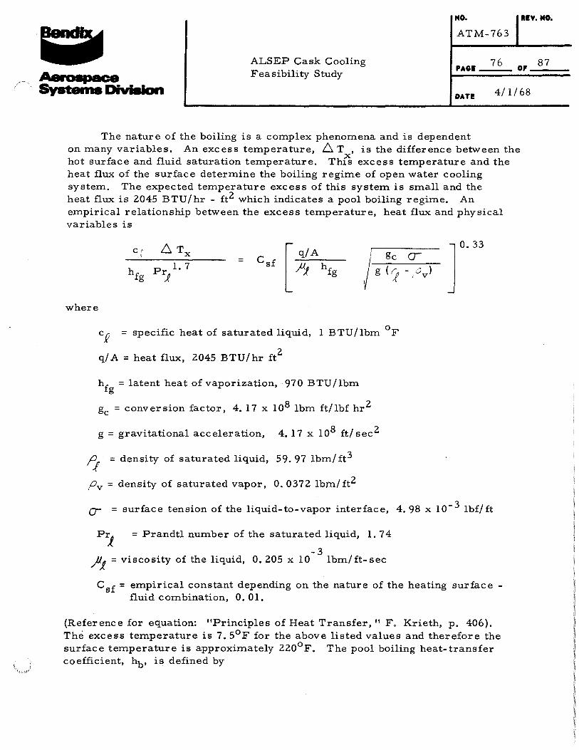
: : . ~ NO.
ATM-763
ltl¥. NO.
ALSEP Cask Cooling Feasibility Study
PAGE 76 0, 87
Aaroepace Systeme Division DATE
The nature of the boiling is a complex phenomena and is dependent
4/1/68
on many variables. An excess temperature, 6. T , is the difference between the hot surface and fluid saturation temperature. Thfs excess temperature and the heat flux of the surface determine the boiling regime of open water cooling system. The expected temperature excess of this system is small and the heat flux is 2045 BTU/hr - ft2 which indicates a pool boiling regime. An empirical relationship between the excess temperature, heat flux and physical variables is
6. Tx c r i \
[ q/A gc csf = j g <J hfg Pr
1 1.7 fiJ hfg
where
cR = specific heat of saturated liquid, 1 BTU/lbm °F
q/ A = heat flux, 2045 BTU/hr ft2
hfg =latent heat of vaporization, 970 BTU/lbm
gc = conversion factor, 4. 17 x 108 lbm ft/lbf hr2
g = gravitational acceleration, 4. 17 x 108 ft/ sec 2
I} = density of saturated liquid, 59. 97 lbm/ ft3
Pv =density of saturated vapor, 0. 0372 lbtn/ft2
r.33 a-- u )
' v
a- = surface tension of the liquid-to-vapor interface, 4. 98 x 10- 3 lbf/ft
P1 = Prandtl number of the saturated liquid, 1. 74
-3 JiJ = viscosity of the liquid, 0. 205 x 10 lbm/ ft- sec
Csf = empirical constant depending on the n""ture of the heating surface -fluid combination, 0. 01.
{Reference for equation: "Principles of Heat Transfer," F. Krieth, p. 406). The excess temperature is 7. 5°F for the above listed values and therefore the surface temperature is approximately 220°F. The pool boiling heat-transfer coefficient, hb, is defined by

: : I •
ALSEP Cask Cooling Feasibility Study
MO.
ATM-763
77 PAGI
IIV. NO.
87 OP
DATE 4/1/68
q/A ~T
X
and has the value of 273 BTU/hr ft2
- °F.
Therefore the thermal analysis has shown that both the closed and open water systems are capable of holding the RTG cask at or below a temperature of 220°F.
5. 5 Cask Shroud Removal Investigation
Although the concept of a shrouded cask cooling system represents a highly efficient approach to the problem, it also presents an interference problem to the radiation cooling of the cask on the later portions of the flight. Therefore it is necessary to include some form of removal of the shroud in the total system design. The two removal techniques which were considered in this analysis were that of post launch mechanical removal or post launch self destruct of the shroud.
The problems encountered in the mechanical removal of the shroud were the many degrees of freedom required of the shroud to clear the cask mounting hardware. For a rigid shroud it appears that at least three separate pieces plus a mechanical release system (probably thermally actuated) would be required to be able to pull such a shroud away from the cask. In addition these mechanical withdrawal links (springs, etc.) would have to be oriented in different positions.· Consequently the high complexity and probably weight penalty of such a removal system led to the consideration of the second type of system, i.e., the self-destructing system.
Once the cooling GNZ system has been shut down in the post launch sequence, the heat output of the R TG cask will increase the shroud temperature (by radiation heating). Therefore a material is required which is structurally sound at the shroud temperature during cooling and which will decompose at an elevated temperature without damaging the cask and its contents.

NO. RIY. NO.
: : I ~
ALSEP Cask Cooling Feasibility Study
ATM-763
78 PAGI 0,
OAT! 4/1/68
The actual form of the decomposition could be that of melting, charring, or subliming. However for melting, such as would be attained with a thermoplastic, the subsequent deposition of material presents a problem. On the other hand most subliming materials contain highly reactive chemical constituents such as fluorine which could attack the cask surface, etc. Therefore the charring materials appear to present the most attractive approach. Such materials as certain phenolics decompose in the proper temperature range (300° - 400°) and with the proper filler result in an end product of only a fine ash. The only real question is the actual time of decomposition in the anticipated environment. If this time were too large, there could be significant overshoot in the cask temperature above that of the equilibrium space radiation temperature. Such a temperature overshoot would increase the decomposition rate, but this type of interaction would require careful study to insure capsule integrity throughout the shroud removal sequence.
87

··-$---suPPLIED &Y lltC D&..C.N CCfiP. j E~~T ~l(AWAY, l L.L, N.V. Oft IE~L.. lfi .USY ITtMS l.t.,tl,~.ii.JZ.I4.15 WITH BQL.T'S.Wt~D
, ITEM IO·S~ IACHEND OF ITDo\ 10 IN PLACES ' :IIGWII USING ~ 11. A'IA. FIKTUR&.
£. ALJee; ITEM 1$ IN PLAC.C: .U IWOWN,Dit'LL .ti&CU' MDLd IN tTaiiS tl't ~- HOLII IN CUPS OP ITN l.A..PI\..OT.
a
.,..-r::;
.o•
Drawing 1
TYP 4 PLACES
-......... .
...... , ITEM •rz. OMITTED FOR CL..t..R'tT'"T'
AL.IG\1 &liSTING fotOLKS -"NO MI\TCH tMttLL • ~&I DIA. 4 PLACES
1:J p.!
(JQ (1)
-.]
"'
~ t-3 ~ I -.]
0' w

.. .:.
T :
AT
M-7
63

NOTE~~
~THIS AUIMk.Y SHALL M OW UNIT wtTH INttltC.HANGtABLI t.L!.I!" .!M$ a THAU G. THE ON\.Y Vlt.RIATION 81"TWEEN ti.-.~H lr&UMM.fltt. A.Ra THI! SLitYEft THEM&IL\11:& .... ND TH£ HARDW .... ~E KQuiR£D F"''R SE.C:UR\NG "THEt..t ..
!'------+------~
~ -=t \. I I '.. I .
"-··- I ___ /·
~~
Drawing 3
a
~
.--~~-~
I I
, .... ---;----.............
.. _i;
! ', I \
\ I
i \ -----;1------~
/o I
------!-
\
'""' ··~
I I
I I
_,./
//'
/ _/·
18)~£F
~ I ,0-;v FOO.' H

REF
VIEW A-A
Drawing 4
aO•DcD
YJ N
. ..-. 1'1 > >fi.:.L_ I 1-j
ir·~---.. ~ ·------·- , .. ~ :~lt:=kt~\mu ~~··=~~.~~-··•~•• /1~ ·0' ·w
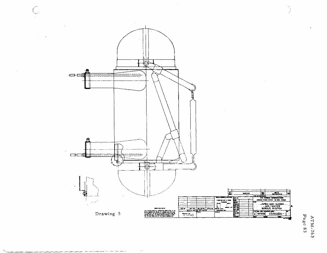
~--
!' I I . I r----\
','-......_ __
1•1 I
I I
I I
I I
I :I I
I I
I I
I \I
I Ill I 1
l:: -:=::
I I
c
I
AT
M-7
63
Pag
e 8
3

/flort!"s: ·.t.: · • /~~--..y,.r,.,,v • .e1,1V rv~.;.,... Sn<?VT'S ;n, LU" G'<'<::.4nr.D _;... S'/.<V ~.....,./A'S". ·_~"Z .~_,.;-~ 2<: .QC'< /<11 /.:.-_/8 ,t-b dN' .WPAf"R 84'-. 3. *·-/$/./?, /,,2/ .,.,.y ,r;,_,;,. ~#..:::: 4. C.:?~ /'?H.P C.o;'N'fTA'N'TA'N '7h'4"A'"""'~"'".r · .n-~r,.;:w' 24 ~A- KMr .r • ..;,_ .ry,qr. r. ~
. .5; c/9~ ¢ --~ 5-/VA' R&<"--~ <>N".r ,..,.,__..H (LP ....W~
6. /l.tt: FhVA'G' A'.>f'Y' O.ct<7PAIT':'tW'J' ..9,v.? /A'J?:<'v~/C..V PV.rnt'#Al?'I:>N' n:> ~ .PIRA>R~ . /N ,/9CUN'rAt:Jc. <: ELJ /9R~/9 ....9NP qLoYE.J V.rdZ' .. - Vfr AJ#' ln/f'tii"'Jff' /Yt6"1:::"ttr.r.FA_,y P~CAVT_-'~N.r
-.?'t' A'~/P PA~.1'9?'r _........,...va CoA/ r~/A/A-7/t?N.
~ rN.-A""'*:JCdt:/~F OY'S"rAt:-~;9,?";1t::1""" /N'f,r-,;f'Vc,r-/~AI"J'.' . . ~ CVT lWIItA/FY ~r ~i!ii+tf;FT# o~ ;V'/ ..,rar- ~NP .s?l'?/.P .. 2-F ~£Nt?'r# 11:1~ ~N'D,.
IJ; ~f'CA77 ~ ..7"1YM::"r/IH" A'NP .IV'64!P ~RBs>P .,....,P-~/. . . iC . S"nf'~ R4".J:/rl4£" <!JY .......... .O/""<J' /YK»"t:C ~A'PfAnP...,.«--Iil6JV?.Z>
. /O"V8 sr_,.;nr D.IV.J: )(<
..,-8: · )'~~r ~~ -~mY~~ f_ .... A'TA'.-I'M"<>IVE,.--Tr_...,...,~.AW...-c~ • ·: A'A'.P. :4!r /#TT/'PV...,L5 t!l~'....:r ~~ ~L..9~./2'?P F"t::?R/1 P-er~~ c:l,- .et7 F4"2:.7; - , ·A~P,,,t?~/l'tr Y/?A'A"/..r#co#?'/'~ 7"""l::7 ~H...-17.A'...,.A""'",-.,..p ~ -·
9:' - .l'fi<AF';;'"'NC'£ .4.XA- PR.I9--""? ..V4. :t?:!$35-!J . ~I"' i
. ~ ~-A.+t'F. Bl(/1 P,P/IIV/Ntf ,M.. 2335.S4,_
'/Y-o .~A'":".._,..- 4:t<;9- ·P"P/9W/A4 Ab 2'33a,-41!1
:/2, . ~"""'A'AK'.,..:- ,8,,9 PR-"W..Vl5' /16 <?~3~34!1
fl.'<·>
ltr , :. ,~~ ·
• ...... ¥ ~
.. "..! ::· . ~ .·.
it,:~:, ~, · .-··· ·- ~: .
-~ ATTA CII.#€1/T
____{a,_ ~;._E)
~ . . - ~~j
_T-16¢-T-1 7
ATM-763
Drawing 6 Page 84

t---------~-.,-----14.88~-----'------,-------+j
'NOTE"Si ·
E):., ..k'- r/C :s- 7Z) Be" /.V.'>r~t) ~/V Cl?NV4?1' $/./)4 or ~,...;::o_.....,..-9<:. .SH4i'l:.C F-""/-'IVG-~ P~N.erL .5_ /~r;py El"'k'H ~C N/?"W 7/~i' AQ. S";h'dJYA/J'9T_.c::i::;'/A//c::w'£
F'4'0r .F...-'?i:1A'? ~.-W/Rr £.;¥'? ...9.¥..::> /"JT /A/T.trRY/1/S" or~ r.r~r • ~ /9~727? ,..q:t,.q If- P;,s-r-9NC"r ~T ;20 ,-~- ,.o?PA::'Y ~/f'~7"4Z//V.r: V.-"9A"#IS"# c-r;;TfiT//Vtf 7"V I!!"'<"?C# -"'WA='k'AfR
4. 7?1'E.I'?M~CCI~P#!£ //Y'sr~.(r':~;::;;o...y /NS'7.-P£1C7/C.\ ~: --: ;:;:~;;; -:l~;g,:~ );;-~%-R'~s-~fl'-~-V~~tf7"# Cl#r.:.vo 'C , ST'..J?~S.S_r?.-C/6"}/.£" CJY f'~PI.-Y"'7' AI'IC",k"E~ .:r,r;:r;;-9p.s PER. Mfl .. -W-t!U,fl ~~ svesr:'!/971F"_.!'#cy
1; ~~~,z~.:~~s;;--~~E~~:='~M:%~.-v~~_s~~~:.;~%h' AYa <T_'_ <7~ P.SGV.-£/SE ·~y OT,#c,.;f' A/CCE.SS~/PV PRCC.-9..:::.-'T.-'o..--v'J" t7 ,/jY_di,P &JA~'*9 !f'" -""?N.O 0:1.N"FJ'9-Milf'AT/o.,Y . :\
/:i_ ·~~~~; ~t;' .,A-9./fl: S.,¥0 ~A/ Re.A"Pese,v~ ~~-:: r::~.!J: ..r~~~. * :r. ··,, . ~~~~@;.C"O.iV'S1?9-Nrh'# T#E'R..A?OCOVP.t:C J.:Y#c.r/'.;.?.A/ ·· ';;t;f~:-::~e • .-/$/1. TYPE T • • _
T8
I -:"r-;-_2 __
._
/VP "tjC. A-I 7 ,1-JC.J.'/ ~N'·J
{No 6<:.A.:.G)
-~---+-- ---- . ------ t
'1 -~--
-~
ATM-763 Drawing 7 Page 85

H
G
F
I I
t ' •
c
8
A
8 7
NOTes:
I. CoP~ R....v.c? co....vs-;·o;;9NT.;9/N r...H:,f'ft?oct::u.,.P?£ .rv....vc??t"N 24 q/9, H/N-:
1 /1 s;.-9~ ry~ r
2'., F....,.c# 7/::- ,i-V/-RE" S"#c:;1.J-V'# .R&PRFS,rNr.$ c::.t...ve-- PA//~ (Z H/~S') 3. ,;9tC ;C"/.N'...,c:' /9.SS Y OPE-"'?AJrA:::J...V..J" ,-PN-0 /A.rr"VVA-"7ifi'K//P77t:IN /H'S"nl~t';977oN'
6
TZJ 4C PC.Rrolf'/i?.t:P /#<""1 Co...vr~euce-o A/f"£";9 ~N.O '7~CV6.$ VSIYO,- V.J"tr ;9-'VY' Drhf!rltf N(!;'"c:"'trS.r~,Py PRECAV//<:IN'..:s"' ?"?:' A'J,/0/P PA.-JA,;;£ ,.,,.,..('.) C",A./?"'A;'Y?/N,A!-77t:JN"
4; ?Air,.tf'M"Ct:'V/='t£ /N.r/ACCA'77o# /N~/;'?(..ICr/0/VS I
tZ CV'T T;J#!rA/T'Y ..=-oor CC....v'9T# OF h/.r:"i'C ~0 .ST.IT'/.P .,£>$" .!'47YifT# o...Ve- CN.P • .d Coc.-97T 77c ..rv...vc-;-.1o....V .-9.-"V'.o /1/.:::,;;·p ?ER 8 s-0 /S?P ¢/
"C .S//PCS.J" Rr.::'~I'V.£ ..e.- A"trC£?./..v·;r #/c-A'""CC .. :!i7'7f~.;9P.J('7nrM/1b.s)~.R ~/C-JIY'7!1'~// J'z, s-P,e ..:r.?7'?.-9-T'l:: a.-Y'C y.
5. /OG?VT/r'"Y c-_,.,c# 7/C #e~ #1//T# ¢ #Gt _,...#dW# ;"// ....q:;,/A.?'"" OAoff""" ~~r ,;tt::".t(#t:J.I*? ,;C'"I"'?t££ ;¥/;'f'r CN.O ,.,./V"..O /9/ //V'?"*€,P VAl:S OF" .;r" r~~r ~A'~,P ~/P A P/.rT"A"Nc-t: q,- 2e> _,=-.;c-r; .-9PP~y ~7"1:!!7:://;,.-rr VA/rN'/f# C"'oAT?A/tJ .?Zl .JIIIIeH ,..,,.,,. ..... ..,.,
" /;<;.f;;r'"-'?VM47Vr/t:~N' 7?J BF tCOC;'lJr<!fZ} G1N PAr dF" ~VNT"/Aif' ~A?C' F;N/N¥ ,1'~ C""_,S"k' ,.SSI".PIAY<Y'
7. PAINT AL.£.. AI!.E~ EJ.IC.t..O~C.D BY C-.eo$5HArt:.HG'.I:I 80.eDIIt 1t11t!U?¥ N/.A' EH/r"'r"""*~6 (~ C,.8) .ltACA:. _.-.A/#'7"_,/.t!. /14/C08aA/O o.c c:::-+r..,.t..-.c:: .4.~~ ~_,.,e.l 8,.A/f4P..
15.38
·- 4.50
I ! ---+---+--
' I I I
I I
-+---+--i i
t------ 1e.oo eo.oo
1'----------- 24.00
r-sz
30.00
+
4
T;t JUNCTION·· Wf.LD TO SUBSTRATE
0£TAIL A NO 5CAL£ TYPICAL
5££ D£TAILA
2 ltELIAIILtn
.IPPI PIEIICTUM z• l11
NICKEL RIBBON
lll f VI S I 0 IS ""' INTI ll'n'l
G
F
E
D
c
8
ATM-763 Drawing 8 Page 86

' J-3: ~ ,;'Pt!Z/CI/4" <::::::',.P$?"'~ ~ ~ ;11//7/Y c-~-:s-G?'P~ .::I'd<:::' h"'4f+r AtJ~#G ~p-.#4 ~~~ .J?'/9~
(1· /<'TT-"'C# ~1S' .17> <fFhWP#/?IrSPRflk:ES' ~A' P~<J 40<3 ¢ A'~~ /N.f"T~J'
&;' CdCRnY /AI'I£70 7;/C .]V..VC77QNS' ~LfiSO-r?/"-?/
6 :;?'c 7~We7"/"'A/ ~0 r<;:>R /..VJ'"?"RV~/9;?dN' A/.- /~ T.-M'V T-69 /<?V'fT .4C A'.-'?~-1' 4>~ .. ~ /~ .P//9. ?Z!I ..-'1?/#/..A?/.i!t£ Bt£;¥-.1!:' P..R&"r..-A:Ys~ ............. ~.N? cHs-..r-~ :rt:/..f'.-""""A'C~
?!'?/& <'~J' -T-$2!1 T~ T-69 --"?VfT 8<r ..-ft1<~?>!':'.<> ,<;'l9C/~&Y .A!M9Y rA'O>P? c*',;-' SV-1'?/9<=6' y-~f ~ez /e::ve:z::::; #/ r-/;psr ,...q4Z'/er-~ ~ A .,.A?.....-.....v....-......,.v....-? c:::',..c:- 2 A¥~:r~ .....=-nv..n:? C'/l'f~ .:>P~ccr
8- ,;kc /'/A/.-9-&' .AJ-ff Y d'Pt:!F7PH;1"'"'1"f:-'.VS" ..A"N.e' /.A/Sr,..c?P,-.?~_,.7741/Y /...V$"~ I""'??C?A/ i"z::; 4tr ~..+?4'"".0 /A/ A1 C~N~C.6'27 #~, ~oHS""s~- t:Y..fir .;9;;YY ~J"7iiltt'7P #.n:-~s..-9-....PY ,P"/P~NV//<::~A""f 7""'?7
, /<'HM? .0#_.,"'!:"£ ,....,.,...., CdN'~_./A/Rr-A"H• f
19 /~77--..- """'<=¥ ~"*"''-"' :p(:' ,11-6 s""".v...v ,.,-,-9 ..-;...vT<=>N'F r-<>"'r- ,,.-""'>_,;., /"'-?er N;,ce,r.,.;;yc (j
""' ""'"' '~' / ( DWG NO, 2334-983 FIEF)
I
I /fN~ ~T' ,/#TFRi4'1t.f &1/" d'" ~.47!7 ?""'~~~ ;"'="e:J,P /'9 ,£Mfr..-??VC4" OT /EO ~liFT- ,....,.,,P,.c=t:' y" P.,.,e;t?~77W: Y~/...r# e:t::~""!77N'<7 7'?:' ,r?9C.H /"'7~k"~
T;f; JIJNCT'ION WELD TO SUBSTRATE
{•~ -REMOVE COATING IN ARf:AS SHOWN
FQR WELDING
NICKEL RIBBON (ON IICJIJNTING PLAT£/17«> {-n..1 "'""~~)
DETAIL C TYP VC INSTALLATION ON
CAPSULE SURFACE I MOUNTIN. PLAT£ (T-80 THRIJ T-89)
NO SCALE
~WIRE 300 SERIES CR. AWG #cS MAX D/A AS REQD FOR STRAIN REUEF OF S£/fSORS (rez- ra9).
. '----- T-64 1 T-601 T-6 8 (Ro)
.5ECT/f'#.~
T-66 ----1---, I f.l __
T-76 l T-78 1\- _,
II\
II I I I
T-86 11 r1--l '
-I+-!
' ' ' \ \
\ \ \ \ \ I I I
ATM-763 Drawing 9 Page 87