Embed Size (px)
Citation preview

NAVTEX RECEIVER FOR GMDSS
Operation Manual
SNX - 300
SAMYUNGENC CO.,LTD.

1
CHAPTER 1. NAVTEX OVERVIEW 5
1.1 GENERAL 5
1.2 BROADCASTING 5
1.2.1 FREQUENCY IN USE 5
1.2.2 LOCATION OF COAST STATIONS AND BROADCASTING TIME 5

2

3
The following marks are designed to prevent any damages & injuries to guide correct
operation. Pay attention to the below guide line for exact use !
If you ignore “WARNING”, You may get seriously
injured.
If you ignore “WARNING”, You may get injured &
damaged for your properties.
� Don’t disassemble the equipment at discretion.
� Be careful the equipment not to be exposured a
liquid like rain and snow.
� Use rated voltage regulated at manual,
Strictly Check the polar when it’s connecting
power.
� The equipment is sensitive electronic device.
Please install proper place without shock and
vibration.
� Observe storage and temperature under operating
described at manual.
� Don’t touch resistor and Trans on the PCB, which
is delivered from warehouse with tuning
correctly.
� Don’t pile anything on the equipment.
� Please be aware of the Manual before operation.
� Please be kept on the Manual around the equipment always and not to be lost
� Once it is fired or smoked, Turn off the switch immediately.
� We appreciated that you purchased SNX-300 NAVTEX RECEIVER of Samyungenc.
CHAPTER 1. OVERVIEW
PREFACE
WARNING
CAUTION
WARNING
CAUTION
4
1.1. GENERAL
NAVTEX is an abbreviation for Navigational Telex and it is a Telex-Broadcasting system of the
coast stations worldwide. NAVTEX of the coast stations broadcasts not only the defined ID,
but also all the information on navigational warnings, weather warnings, SAR and other
marine warnings for navigational safety of those vessels equipped with NAVTEX Receiver in
the coasts.
Consisting of a part of WWNW of GMDSS monitored by IMO & IHO, NAVTEX with “Narrow Band
Direct Printing” is a receiving system on board, using NAVTEX Receiver.
NAVTEX is designed to receive all the marine safety information service made with the letter
broadcasting both in English and in Local language on International Frequency : 518KHZ and
on Local Frequency : 490KHZ or 4209.5KHZ. The services provided are mainly divided into
3(three) categories as follows ;
- Navigational warnings such as iceberg movement-related safety.
- Meteorological warnings such as typhoons and wave heights.
- Search and Rescue activities by Coast Guard or Coast Station, including any urgent
warnings.
1.2. BROADCASTING
1.2.1. Frequency in use
IMO recommends that navigational warning, meteorological warnings, information on SAR
and other information be received from NAVTEX stations and broadcast on 518KHZ for
English, on 490KHZ or 4209.5KHZ. Both 518KHZ for English and 490KHZ for Korean have
been used since March of 1999, but Japan uses 424KHZ for their local language
exceptionally.
1.2.2. Location of Coast Stations and Broadcasting Time
The location of broadcasting stations basically depends on the transmitting output and
the conditions of the electronic wave in the region. The stations are normally located in
the range from some 250NM to 400NM.
In fact, the major factors that decide the service region of the broadcasting stations are
“Broadcasting Station ID” and “Broadcasting Time Plan”.
It is decided by IMO Coordination Committee. As the broadcasting time of each station is
every 4hours, set not to exceed 10minutes, the broadcasting between the stations is not
overlapped. Chapter 8 is covering the broadcasting time of each station in neighboring
5
SNX-300 ZCZC B1B2B3B4 Time of Origin(Broadcast Time) Series ID + Consecutive No (S/N)
countries.
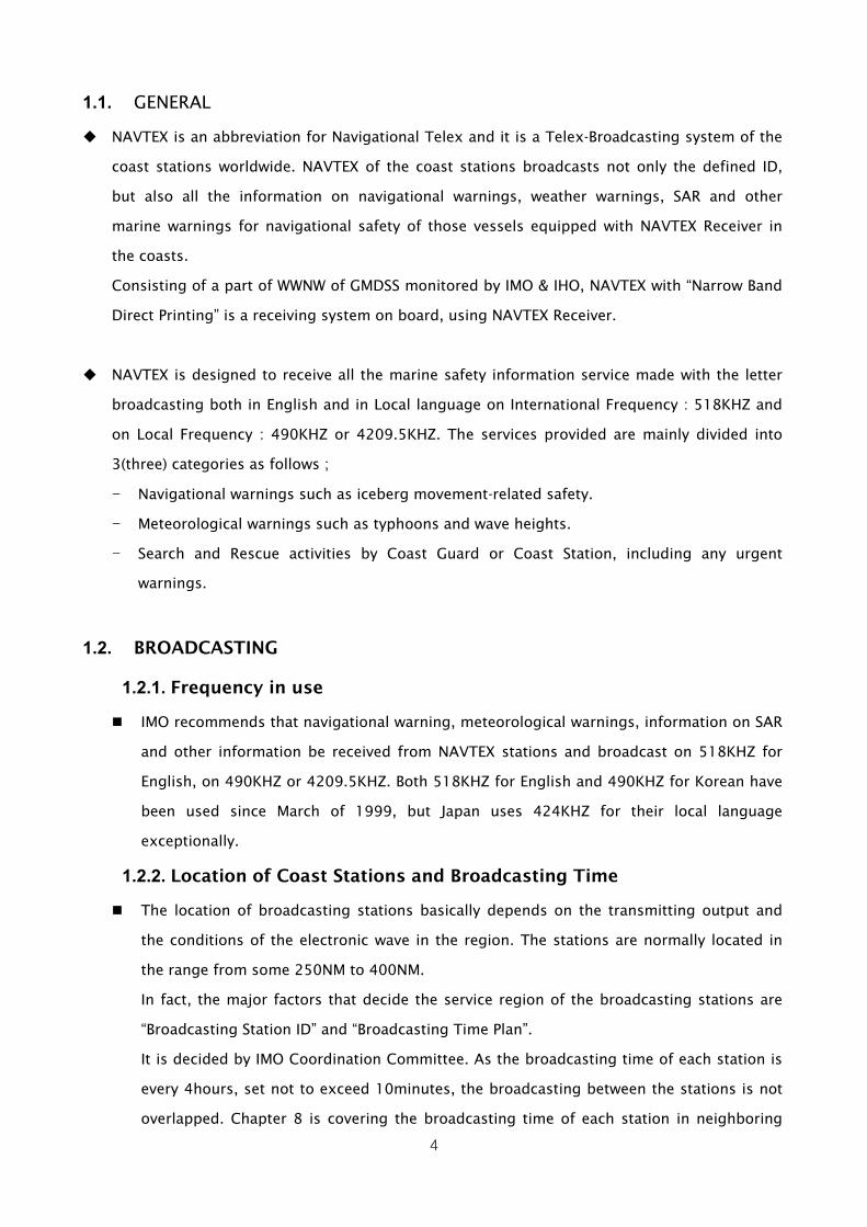
1.2.3. Transmission Mode
According to M.625-3 of ITU-R Recommendations, as NAVTEX broadcasting employs 5 bit
code as ITA No.2 Code System (that is used for international telegraphic transactions by
CCITT Recommendations F.1) only 32 characters are available.
As it is impossible to display Text, Figures, Marks, Shift Signals only with 32 codes,
the system allocates the conversion signals and the figure conversion to Shift Signals and
additionally allocates 26 codes.
The 32nd code is used for the Korean Shift code. 5Bit ITA code is converted to 7Bit and
then
transmitted. All 7Bits are composed of 3(three) “1(B)” and “4(four)”, “0(Y)” and used for
checking any errors.
Besides, the system works on correcting any errors in the way of FEC(Forward Error
Correction) that the same characters are transmitted at the back of 4 characters(280ms)
for comparison.
M E S S A G E DX Signal
M E S S A G E RX Signal
M E S M S E A S G S E A G E Transmitted Letter
M E S S A G E Display & Printer
Letter
< Chart 1-1 Message Transmission Format >
* Notes : Such cases may occur that the conversion code(Letter, Figure, Korean) is not received
and that the printing is faulty is faulty despite normal receipt of data.
1.3. Message Type
The message type of NAVTEX broadcasting is as follows. In transmitting, the system transmits
Message for matching with the receiver after transmitting Phase signal over 10seconds. The
general message type is as below.
[ 518 ] 2006. 02. 08 [ 490 ] 12 : 30.32

6
< Fig 1-1 General Message FORMAT >
1.3.1. Transmitted Message Type
ZCZC B1B
2B
3B
4 Message NNNN
① ZCZC : Start Code
② B1(A~Z) : Station ID
③ B2(A~Z) : Type of Message
④ B3B
4(00~99) : Serial No., exception “00” (such as SAR message)
⑤ Message : Main messages
⑥ NNNN : Termination Code
Type of Message Description
A※ Navigational Warning
B※ Meteorological Warning
C Ice Report
D※ Search And Rescue Information/Piracy and Armed Robbery
E Meteorological Forecast
F Pilot Message
G AIS message
H LORAN-C message
I Reserved presently not used
J SANTNAV message
K Other Electronic Navigational Aid System Message
TAG
EXIT
Output
I 0 N T L 2 O C 3
3

7
L※ Navigational Warning(additional)
M to Y Reserved presently not used
Z QRU(no message on hand)
< Fig 1-2 Type of Message(B2) ID >
※ Notes : For the boldfaced A, B, D, L messages, it is forbidden to exclude Display on the receiver
or Print-outs.
1.3.2. B3B
4 Numbering
Serial NO. (B3B
4) – Serial numbers from 01 to 99 are given in NAVTEX message.
These serial numbers are given by NAVTEX coordinating station. As a special figure, “00”
is used only for significant tests such as rescue and it is unconditionally displayed on LCD
screen. In case NAVTEX receives any message with this kind of special figure, it is
designed to always print out whatever message it is. Therefore, the printing is strictly
controlled. Other serial numbers, excluding “00” are memorized in CPU and used to avoid
printing repetitively any completely received text.
1.3.3. END of RECEPTION
NNNN : This means the end of any received text.(End of Message)

8
CHAPTER 2. SYSTEM
2.1. Feature
The equipment is fully compliant with M.540-2, M.625-3, IEC-61162 Performance Standard of
IMO Resolution MSC.148(77)ITU-R Recommendation.
The equipment has 2(two) built-in receiving devices both on English channel(518KHz) and on
Local channel(490KHz/4209.5KHz).
Compact and light design creates the easy installation available.
The operation of power supply prevention circuit makes the input power cut in case of less
than DC 10V or more than DC 36V.
It can indicate the frequency on which any text is being received.
In case of failure in normally receiving, it shows the reason on LCD screen.
In case of power on and performance of its self-diagnosis test, it is possible to automatically
check the status of the equipment inside.
In case of receiving A, B, D, L type messages among the received messages, it is indicated on
LCD screen and a buzzer is activated.
It is available to select Station and message ID received.
It is possible to store more than 200 pieces of data, which is composed of 1600 letters per
channel.
For any received message, it can store for 62 hours.
It is available to select any Station ID for reception refusal and to select any received message
classification ID.
It does not store any message that has more than 33% error rate of received letters, or that
fails to display in a normal way.
The supportive languages for this manual are in English, Chinese and Korean available. This
manual is written in English.
2.2. System Composition
ITEM MODEL NAME Q’TY REMARK
NAVTEX Receiver SNX-300 1 EA
ANTENNA(active) SAN-300 1 EA
POWER SUPPLY SP-300AD 1 EA OPTION
PRINTER DPU-414 1 EA OPTION
< Fig 2-1 SNX-300 Composition >

9
2.3. Conditions of Receiption and Display
When the error rate for the received character is below 4%, the message is printed and
ID(B1B
2B
3B
4) will be stored in the memory to protect from printing same message in the later
stage of receiving.
Receiving should be stopped when the error rate for received character is up to 33% (over 5
seconds) and the content should not be stored in memory.
(In case of not receiving "ZCZC B1B
2B
3B
4" properly, receiving and storage should be stopped) In
case of not receiving “NNNN" properly, display can be done while storage into the memory
should not be done.
Contents ID can be stored up to 200 numbers, but in case it being over 200, the memory is
erased from the oldest one.
Stored ID will be automatically erased after 62 hours passed.
B1 and B2 data can be memorized over 6 hours after putting the power off.
The allocated message as endowed with its serial number “B3B
4” to "00", they are always
displayed whenever they are received.
Selection of transmitting station of serial number “B1” can be made and confirmation for the
selected station in the menu is possible.(At the delivery, all messages from transmitting
station (A~Z) is set to be receivable).
It receives messages type of serial number “B2” and it confirms type at MENU. (It sets messages
of all transmitting station (A~Z) in order to receive message when it delivers.).
As message type A(Navigational warning), B(Weather warning), D(SAR) and L(Warning additive
to “A”) are very important warning message, they are not allowed to set forbidding the receipt
of message. “D” alarm is continuously printed out while “A,B,L” can be set for printing out the
alarm as an option (At the delivery, A,B,L messages are set to stop printing out the alarm)
If receiving letters have errors, it prints out “*” instead of the error letters.
It is possible to display 16 lines of message on the 5.7” LCD, and over 32letters each line(In
case of small size).
TAG : The message necessary to attach “TAG” will not be erased. TAG attachment could be
available up to 25% (50 numbers) out of the receivable messages in total.
2.4. PRINTER PORT
Printer is supplied a printer interface port for the users to connect it selectively. The printer
port is a type of a serial interface.

10
2.5. EXTERNAL PORT
The function of RS-422 interface is supplied to be possible connected with NAVIGATIONAL
equipments.
2.6. USER SET LIST
Following Lists are memorized if user set once.
MAIN MENU SUB MANU DESCRIPTION
[1] MANUAL SET INT INTERNATINAL STATION(B1) SET [1] STATION SELECTION
[2] MANUAL SET LOC LOCAL STSTION(B1) SET
[1] MANUAL SET INT INTERNATIONAL MESSAGE(B2)SET
[2] MANUAL SET LOC LOCAL MESSAGE(B2)SET
[2] MESSAGE SELECTION
[3] A.B.L ALARM SET A.B.L ALARM SET
[1] RECEIVE NOTIFY RECEIVER ALARM SET
[2] PRINTER PRINTER OUT SET
[3] KEY BUZZER KEY BUZZER SET
[4] MESSAGE FONT SIZE ENGLISH SIZE SET
[5] DISPLAY LANGUAGE SELECT USER LANGUAGE
[4] USER SETTING
[6] 490/4209 LANGUAGE LOCAL FREQUENCY LANGUAGE
[1] DIMMER AND CONTRAST LCD BACKLIGHT CD & CT SET
[2] 490/4209 SELECT LOCAL FREQUENCY SET
[3] LCD REVERSE LCD
[4] PRINTER SPEED PRINTER PORT SET
[5] INS SPEED INS PORT SET
[6] NMEA SPEED NMEA PORT SET
[5] SYSTEM SETTING
[7] DATE/TIME SET DATE & TIME SET
< Fig 2-3 User Set List >
11
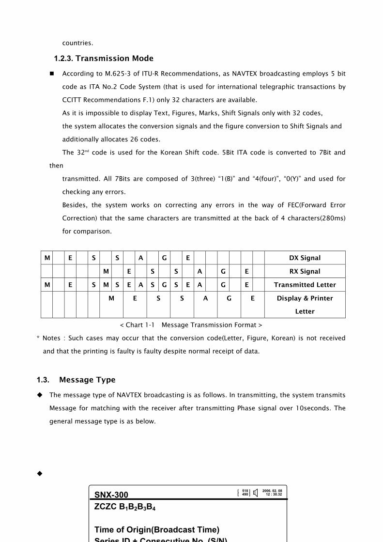
2.7. SOFT KEYS
The following is decrypted the frequent Short Cut for User’s convenient.
N
O BUTTON FUNCTION NO BUTTON FUNCTION
1
INT’L STATION MANUAL SET(B1) 2
INT’L MESSAGE TYPE SET(B2)
3
ALARM OFF 4
LOCAL STATION MANUAL SET(B1)
5
LOCAL MESSAGE TYPE MAN. SET 6
MESSAGE LIST
7
CONTRAST HARDER 8
RECEIVER SOUND ON/OFF
9
CONTRAST LIGHTER 10
LCD BACKLIGHT DARK
11
RF RECEIVER TEST 12
LCD BACKLIGHT LIGHT
< Fig 2-4 SOFT KEYS >

12
CHAPTER 3. SPECIFICATION
3.1. Receiver
① Receiving Frequency : 518KHz , 490KHz or 4209.5KHz
② Receiving Modulation : F1B(Narrow Band Direct Printing)
③ Sensitivity : 2uV e.m.f. (50 ohms), 4% error rate or less
④ Antenna input : 50 ohms for NAVTEX Active antenna
3.2. DISPLAY SECTION
① Type of display : 5.7-inch LCD, 320×240 dots
② Back-light : For LCD and key board
③ Dimmer control : 10steps adjustable (Selectable from keyboard)
④ Contrast control : 10steps adjustable (Selectable from keyboard)
3.3. POWER SUPPLY
① Input voltage : Rated Voltage DC 12/24V (10 ~36V)
② Power consumption : 10 W (at 24 V dc input)
3.4. ACTIVE ANT(SAN-300)
① Receiving frequency : 518kHz, 490kHz and 4209.5kHz
② Consumption current : 8Vdc 10mA (Typ.)
③ Impedance : 50 ohms
3.5. Environment
① Operation temperature : -15°C to +55°C
② Storage temperature : -25°C to +75°C
③ Relative humidity : 95% at 40°C (without dew condensation)
④ Vibration : IEC 60945

13
CHAPTER 4. OPERATION
4.1. Front Panel
1
2
3 4 5
6
7
8
< Fig 4-1 SNX-300 Front Panel >
NO ITEM DESCRIPTION
① LCD Display of RX message & various information ② LED Flickering according to the environment ③ FUNCTION Function key interfacing with LCD ④ POWER Power ON/OFF ⑤ MENU MENU button ⑥ ENTER Selectable button ⑦ ALPHANUMERIC Numeric / Alphabet / Soft-key ⑧ DIRECTION Direction button
< Table 4-1 Brief Description over the Front Panel >
4.2. LED & Buzzer
This is ON/OFF function for beep ringing as all kinds of button on NAVTEX key pad is pressed.
Besides, when alarm occurs, it is designed that alarm function is endowed to the buzzer to
enable user to detect the alarm conditions.
① ARM(ALARM) : When alarm occurs, LED is flickering.
② INT(INTERNATIONAL) : LED is flickering when it receives International (English)
broadcasting.
③ LOC (LOCAL) : LED is flickering when it receives National (Local) broadcasting.
14
Alarm is activated with the following conditions, use to stop the buzzer.
Alarm Number Alarm Text
001 Navigational Warning
002 Meteorological warning
003 Search and Rescue Information
004 Receiver Malfunction
005 Built in self test failure
006 General Failure (Clock, Printer)
< Table 4-2 Alarm List >
4.3. Button Description
NO. Type of Button Description How to Use
① ALPHANUMERIC
It shows numeral input keys of special characters, Numeric and Alphabet. The relative numeric & characters are displayed whenever pressing Alphabet and numeral keys. <Soft-key function is built-in for user’s comfort (Refer to 2.7)>
② DIRECTION
It is a button to move to right, left, up and down and also possible to be used on cursor’s movement. It is used to delete input facts as well.
③ POWER ON/OFF
It is a power switch and used in power-on or off. Pressing the button, power on, pressing the button at great length, power off.
④ MENU
It shows MENU list onto LCD.
⑤ ENTER
It’s an enter-key, carries selective category into execution and selects the sub-functions of the main category.
⑥ FUNCTION
It’s a four-function key and manages LCD part of MKD. It’s consists of 4 keys (from the top, F1, F2, F3, F4 key in order). It carries selective category into execution.
< Table 4-3 Button >

15
CHAPTER 5 HOW TO USE
5.1. Power ON/OFF
The device turns to ON/OFF by using ON/OFF key. It turns Power ON if you press key one
second in Power OFF condition, Power OFF if you press key one second in Power ON
condition.
Check if the right Power input into the device and turn ON !!!!
< Fig 5-1 Screen 1 in Power ON >
The following screen shows after 5 seconds later of showing the above screen.
< Fig 5-2 Screen 2 in Power ON >
SELF TEST
MEMORY TEST. . . OK 518 TEST. . . . . . . . OK 490 TEST. . . . . . . . OK 4209 TEST . . . . . . . OK
OK
EXIT

16
SNX-300 ID : HB76 05-07-25 16:53 Size : 260 Cer : 0.0% 171500 UTC JUL 05 WWJP72 RJTD 171200 IMPORTANT WARNING FOR MOJI NAVTEX AREA 171200UTC ISSUED AT 171600UTC TYPHOON 0505 HAITANG(0505) 930HPA AT 23.1N 124.0E ^ MOVING NW 12 KNOTS POSITION GOOD MAX WINDS 95 KONTS NEAR CENTER RADIUS OF OVER 50 ^ KNOT WINDS 130NW RADIUS OF OVER 50KNOT WINDS 350NW NORTHEAST AND 300NW ELSEWHERE FORECAST POSITION^ FOR 180000UTC AT 24.0N 122.1E WITH 60 MILES RADIUS OF^ 70 PERCENT PROBABILITY CIRCLE MAX WINDS 90 KNOTS NE^ AR CENTER FORECAST POSITION FOR 181200UTC AT 25.0N^ 118.6E WITH 150 MILES RADIUS OF 70 PERCENT PROBABILITY^ CIRCLE MAX WINDS 50 KNOTS NEAR CENTER WARNING(DEN^ SE FOG) SEA OFF SOUTHERN COAST OF MARITIME PROVIN^ CE, SEA OFF NOTO, SEA WEST OF CHEJU ISLAND
It starts Self-Test after displayed logo-screen.
< Fig 5-3 Screen 3 in Power ON >
The above screen shows that is calling information and reverse to the initial screen after about
2 seconds.
< Fig 5-4 Initial Screen >
Intl’ messages not opened I N T Intl’ SAR messages not opened
Local messages not opened L O C Local SAR messages not opened
DATA LOADING
DATA LOADING…
CONFIRM
EXIT
PRT
NEXT
In 6 Is 0 Ln 5 Ls 0
FEED Print Paper fwd
Print current screen
Next message
Connect to next
line
I 0 N T L 2 O C 3
3
[ 518 ] 2006. 02. 08[ 490 ] 12 : 30.32

17
Main Menu >>> [1] STATION SELECTION [2] MESSAGE SELECTION [3] MESSAGE HISTORY [4] USER SETTING [5] SYSTEM SETTING [6] SYSTEM DIAGNOSTICS [7] FACT MANUAL
5.2. System Menu
<<< STATION SELECTION >>> [1] MENUAL SET INT [2] MENUAL SET LOC [3] INITIAL CHANNEL INT [4] INITIAL CHANNEL LOC
<<< MESSAGE HISTORY >>>
<<< MESSAGE SELECTION >>> [1] MENUAL SET INT [2] MENUAL SET LOC [3] A.B.L ALARM SET [4] INITIAL CHANNEL INT [5] INITIAL CHANNEL LOC
<<< USER SETTING >>> [1] RECEIVE NOTIFY [ON] [2] PRINTER [MANUAL] [3] KEY BUZZER [ON] [4] MESSAGE FRONT SIZE [5] DISPLAY LANGUAGE [6] 490/4209 LANGUAGE
<<< SYSTEM HW SETTING >>> [1] DIMMER AND CONTRAST [2] 490/4209 SELECT [ 490] [3] LCD REVERSE [OFF] [4] PRINTER SPEED [5] INS SPEED [6] NMEA SPEED [7] DATE/TIME SET
<<< SYSTEM DIAGNOSTICS >>> [1] PROGRAM VERSION [2] LCD TEST [3] KEY TEST [4] PRINTER TEST [5] BUZZER TEST [6] SELF TEST [7] RF RECEIVER TEST [8] ALARM TEST
<<< FACT SETUP >>>[1] ERASE ALL [2] DEFAULT FACT LOAD

18
5.3. STATION SELECTION
It is a required function for receiving broadcasting from a favorable station only. It has set to
receive broadcasting from all stations when it has been released at a factory and the selection
of a required station is chosen onto MENU.
< FIg 5-5 Station Selection >
① [1]-[1] MENUAL SET INT
A. It can be selected an intl’ station (518KHz) by manual with direction keys and key.
Possible to select / delete MEMORY, PRINT, INS one another.
B. The selected station is receiving-rejected by using key, receiving-accepted by
using key once more. Acceptance conditions are displayed onto a final line of the
screen.
C. As select (SETs) key, all stations can be selected.
D. As select (CLSs) key, all stations can be deleted.
[1] STATION SELECTION
SNX-300
Main Menu >>> [1] TX Station Selection [2] MESSAGE SELECTION [3] MESSAGE HISTORY [4] USER SETTING [5] SYSTEM HW SETTING [6] SYSTEM DIAGNOSTICS [7] FACT MENUAL
EXIT
In 0 Is 0 Ln 0Ls 0
SNX-300
<<< TX Station Station >>> [1] Manual Setup of Int’l TX Station [2] Maual Setup of Local TX Station [3] 국제 송신국 초기화 [4] INITIAL CHANNEL LOC
EXIT
In 0 Is 0 Ln 0Ls 0
All Station Select
Clear All
Station
Back to Main
[1] Manual Setup of Int’l TX Station
CLSs
종료
In 5 Is 2 Ln 1Ls 0
SETs Manual Setup of B1 TX Station ID : ABCDEFGHIJKLMNOPQRSTUVWXYZ
MEM : ABCDEFGHIJKLMNOPQRSTUVWXYZ PRT : ABCDEFGHIJKLMNOPQRSTUVWXYZ INS : ABCDEFGHIJKLMNOPQRSTUVWXYZ >> Receivable ID
I 0 N T L 2 O C 3
3
[ 518 ] 2006. 02. 08[ 490 ] 12 : 30.32
[ 518 ] 2006. 02. 08[ 490 ] 12 : 30.32
[ 518 ] 2006. 02. 08[ 490 ] 12 : 30.32

19
E. After set completely and press (END) key, it is saved and move to a main screen.
① The numbers of bottom-right of the screen are as follows.
A. No. of messages not opened of 518KHz
B. No. of messages for Intl’ Rescue and Search not opened of 518KHz
C. No. of messages not opened of 4.2095 MHz/490 KHz
D. No. of messages for Intl’ Rescue and Search not opened of 4.2095 MHz / 490 KHz
② [1]- [2] MENUAL SET LOG : Setting of Local station (490KHz,4.2095MHz) is same with one of
[1] Intl’ station menual set.
③ [1]-[3] INITIAL CHANNEL INT, [4] INITIAL CHANNEL LOC : It can be initialized by using
key and the initial conditions means that all stations for MEMORY are selected.
< Fig 5-6 INITIAL CHANNEL INT >
[3] INNITIAL CHANNEL INT
<<< STATION SELECTION >>>
[1] MENUAL SET INT
[2] MENUAL SET LOC
[3] 국제 송신국 초기화
[4] 자국 송신국 초기화
EXIT
In 0 Is 0 Ln 0Ls 0
ID INITIAL
ID INITIAL ?
CONFIRM
ID INITIAL
ID INITIAL END
CONFIRM
Back To Main
I 0 N T L 2 O C 3
3
[ 518 ] 2006. 02. 08[ 490 ] 12 : 30.32
20
5.4. MESSAGE SELECTION
It shows CATEGORY of receiving characters defined at IMO RESOLUTION and is possible to
select acceptance or rejection for receiving according to an item. However, IMO RESOLUTION
defines that TYPE A, B, D, L cannot be excepted.
< Fig 5-7 MESSAGE SELECTION >
① [2]-[1] MENUAL SET INT
가) The selected-receiving characters doesn’t accepted for receiving by pressing direction
keys / keys and does accepted for receiving by pressing key again. It shows
acceptance for receiving and Help B2 Message Type in a screen. Refer to < Table 1-2
Messages (B2) Identification Codes >.
나) If you select (SETs) key, all types of characters are selected.
다) If you select (CLSs) key, all types of characters are escaped.
라) After all set-up, if you press (END) key, save it and move to a Main screen.
[2] MESSAGE SELECTION
SNX-300
MAIN MENU >>> [1] STATION SELECTION [2] MESSAGE SELECTION [3] MESSAGE HISTORY [4] USER SETTING [5] SYSTEM HW SETTING [6] SYSTEM DIAGNOSTICS [7] FACT MENUAL
EXIT
In 0 Is 0 Ln 0Ls 0
SNX-300
<<< MESSAGE SELECTION >>> [1] MESSAGE SET INT [2] MESSAGE SET LOC [3] A.B.L 알람 설정 [4] 국제 전문형식 초기화 [5] 자국 전문형식 초기화
EXIT
In 0 Is 0 Ln 0Ls 0
All Message
Select
[1] MANUAL SET INT
CLSs
EXIT
In 0 Is 0
SETs B2 MANUAL SET
ID : ABCDEFGHIJKLMNOPQRSTUVWXYZ
MEM : жжCжEFGHIJKжMNOPQRSTUVWXYZ PRT : жжCжEFGHIJKжMNOPQRSTUVWXYZ INS : жжCжEFGHIJKжMNOPQRSTUVWXYZ >> Receivable ID
HELP B2 MESSAGE TYPE : REPORT OF ICEBERG
Back To Main
Clear All Message
I 0 N T L 2 O C 3
3
[ 518 ] 2006. 02. 08[ 490 ] 12 : 30.32
[ 518 ] 2006. 02. 08[ 490 ] 12 : 30.32
[ 518 ] 2006. 02. 08[ 490 ] 12 : 30.32

21
③ [2]-[2] MENUAL SET LOC : Character’s type of Local messages (490KHz,4.2095MHz) can be
selected as such the same method of [1] MENUAL SET INT in manual.
[2]-[3] A.B.L ALERT SET : It can be set A.B.L Alarm ON/OFF by , Press move to Main
Manu after set . D(Search & Rescue Information) keep ON status at any time.
< Fig 5-8 A.B.L ALARM SET >
④ [2]-[4] MANUAL SET INT, [5] INITIAL CHANNEL LOC : Press to initiaize Message INT &
LOC, which means all memory message is initialized.
< Fig 5-9 Initialization of refuse in receiving TX Station >
[3] A.B.L ALARM SET
<<< MESSAGE SELECTION >>> [1] MANUAL SET INT [2] 자국전문 수동 선택 [3] A.B.L 알람 설정 [4] 국제 전문형식 초기화 [5] 자국 전문형식 초기화
EXIT
In 0 Is 0 Ln 0Ls 0
A.B.L ALARM SET
ALARM : A B L
Ch INT : [ ON] Ch LOC : [ ON]
Back To Main
I 0 N T L 2 O C 3
3
[ 518 ] 2006. 02. 08[ 490 ] 12 : 30.32
[4] INITIAL CHANNEL INT
<<< MESSAGE TYPE >>> [1] MANUAL SET INT [2] MANUAL SET LOC [3] A.B.L ALARM SET [4] INITIAL CHANNEL INT [5] INITIAL CHANNEL LOC
종료
In 0 Is 0 Ln 0Ls 0
ID INT
ID INT ?
CONFIRM
ID INT
ID INT
CONFIRM
Back To Main
I 0 N T L 2 O C 3
3
[ 518 ] 2006. 02. 08[ 490 ] 12 : 30.32

22
5.5. LIST OF MESSAGE HISTORY
User can recognize message easily and sort what they want.
< Fig 5-10 MESSAGE HISTORY >
① NO : Number of Message being received.
② ID : B1B
2B
3B
4 in order, Please refer to the 1.3.1 transmission message.
③ DATE : Date of message received.
④ TIME : Time of message received.
⑤ LINE : Line number of tranmission message from station.
⑥ FREQ : Receiving Frequency.
⑦ TAG : TAG ser, Not to delete passed 62hours.
⑧ SAR : Search & Rescue information message.
⑨ N : New message.
⑩ P : Message to ready for printing.
※ It can check both 490KHZ & 4209.5KHZ by . But, [5] SYSTEN SET→ [2] 490/4209
select which can be read message registered frequency only.
[3] MESSAGE HISTORY
Print of
current list
All message
Arrange
Back to main
SNX-300
MAIN MENU >>> [1] STATION SELECTION [2] MESSAGE SELECTION [3] MESSAGE HISTORY [4] USER SETTING [5] SYSTEM HW SETTING [6] SYSTEM DIAGNOSTICS [7] FACT MENUAL
EXIT
In 0 Is 0 Ln 0Ls 0
TAG
Message %
<< 518 LIST >>
① ② ③ ④ ⑤ ⑥ ⑦ ⑧ NO ID DATE TIME LINE FREQ TAG SAR
1 EF00 05-10-25 16:50 11 518 2 EF01 05-10-25 16:51 9 518 N 3 EF02 05-10-25 16:52 8 518 ⑨N 4 EF03 05-10-25 16:53 10 518 5 EF04 05-10-25 16:54 6 518 6 EF05 05-10-25 16:55 12 518 TAG 7 HD06 05-10-25 16:56 9 518 SAR 8 EF07 05-10-25 16:57 13 518 9 EF08 05-10-25 16:58 19 518
10 EF09 05-10-25 16:59 12 518 TAG 11 EF10 05-10-25 17:00 7 518 12 EF11 05-10-25 17:01 12 518 ⑩P 13 EF12 05-10-25 17:02 10 518 14 EF13 05-10-25 17:03 18 518 TAG 15 EF14 05-10-25 17:04 10 518 N
PRT
SORT
EXIT
INT 0.5% LOC 2.0%
LIST
[ 518 ] 2006. 02. 08[ 490 ] 12 : 30.32
[ 518 ] 2006. 02. 08 [ 490 ] 12 : 30.32

23
Move to where the message received, then open by Press key.
< Pic 5-11 MESSAGE VIEW >
How to use SORT KEY
< Fig 5-12 MESSAGE ARRANGE >
☞ Switch NEW/OLD by , Select NEW and SORT then listed recent message on top.
① Time sort received message in time order.
② B1 sort received message in alphabet order of Station(B1).
③ B2 sort received message in alphabet of message type(B2).
④ TAG sort set-message in alphabet.
⑤ ARM sort received message in time order with alarm. (Navigation & Weather, Search &
[ 518 ] 2006. 02. 08[ 490 ] 12 : 30.32
<< 518 LIST >>
TAG
EXIT
INT 0.0%LOC 2.0%
PRT MESSAGE VIEW 1/200 ID : VA57 05-10-25 16:53 Line:9 Cer:0.0 152310 UTC APRIL 1999 KOREA NAVTEX/NAVY SOURCE// ROUTINE : AIR FIRING/ AIR FIRING FOR 2300Z TO 1000Z DAILY FROM 17TH TO 23RD MAY IN THE SOUTHWARD SEA A^REA OF KYUGLYULBIYULDO ISLAND, AREA BOUNDED BY 36-04-00N, 125-48-00E/ 36-04-00N,124-50-00E/ 36-34-00N,124-5000E/ 36-34-00N,125-48-00E. TOKYO DATUM. NNNN
TAG Setup to Message
Move to List Display
TAG Message %
[ 518 ] 2006. 02. 08[ 490 ] 12 : 30.32
[ 518 ] 2006. 02. 08[ 490 ] 12 : 30.32
New/Old
<< 518 LIST >>
NO ID DATE TIME LINE FREQ TAG SAR
1 EF00 05-10-25 16:50 11 518 2 EF01 05-10-25 16:51 9 518 N 3 EF02 05-10-25 16:52 8 518 N 4 EF03 05-10-25 16:53 10 518 5 EF04 05-10-25 16:54 6 518 6 EF05 05-10-25 16:55 12 518 TAG 7 HD06 05-10-25 16:56 9 518 SAR 8 EF07 05-10-25 16:57 13 518 9 EF08 05-10-25 16:58 19 518
10 EF09 05-10-25 16:59 12 518 TAG 11 EF10 05-10-25 17:00 7 518 12 EF11 05-10-25 17:01 12 518 P 13 EF12 05-10-25 17:02 10 518 14 EF13 05-10-25 17:03 18 518 TAG 15 EF14 05-10-25 17:04 10 518 N
EXIT
INT 0.0%LOC 2.0%
NEW
USER SORT
[1] TIME
[2] B1
[3] B2
[4] TAG
[5] ARM
Move to List Display

24
Rescue information… etc.)
⑥ MANUAL sort those message people wants to read in time order.
B1B2 : Set A~Z by direction key
B3B4 : Set 0~9 by direction key
If no set, Entire message is sort by in time order.
ex) USER SORT
Set A on B1 as below, Then press , It is sorted those messages begin A in time order.
< Pic 5-13 USER SORT >
USER SORT
ID : A※※※
ENT

25
5.6. USER SET
User set the Receve Notify, Printer, Key, Operation Sound, Message size, Language, Local
Frequency by direction Key and .
< Pic 5-14 USER SET >
① [4]-[1] KEY BUZZER : Peress to switch ON/OFF, Once ON User can monitering when it
is receiving by Key Buzzer. Press then move to MAIN after saved.
② [4]-[2] PRINTER : SET AUTO let the printer go automatically, MANUAL let the user can
select to printer. Press switch AUTO/MANUAL, Press then move to MAIN after
saved.
③ [4]-[3] KEY BUZZER : KEY BUZZER function of SNX-300. ON is BUZZER available, OFF then
n/a.
④ [4]-[4] MESSAGE FONT SIZE : Functions to adjust messsage font size. There’s three
options Samll, Middle, Large which can be adjusted English message only(Initial size is
‘Small’).
[4] USER SET
SNX-300
<<< USER SET >>> [1] RECEIVE NOTIFY [ ON] [2] PRINTER [ AUTO ] [3] KEY BUZZER [ ON] [4] MESSAGE FRONT SIZE [5] USER DISPLAY LANGUAGE [6] 490/4209 LANGUAGE
EXIT
In 9 Is 0 Ln 0Ls 0
Back to Main
I 0 N T L 2 O C 3
3
[ 518 ] 2006. 02. 08[ 490 ] 12 : 30.32
26
< Fig 5-15 Character Size Setup >
⑤ [4]-[5] User Language : User the directional keys and key to set up the interface
language. English, Korean, Chinese are available. 영어, 한국어, 중국어의 세 가지 언어가 지
원되며, 출고 시 영어로 설정되어 출고된다
< Fig 5-16 Selection of User Language >
⑥ [4]-[6] 490/4209 LANGUAGE : Function to select LOCAL Frequency(490KHz & 4209.5KHz)
with broadcasting, language. Use the directional keys and key to set up 490/4209
languages. English and Korean are supported. The default value is English.
[4] CHARACTER SIZE
<<< USER SET >>>
[1] RECEIVE NOTIFY [ ON] [2] PRINTER [ AUTO ] [3] KEY BUZERER [ ON] [4] CHARAC GE FONT SIZE [5] USER자 Y LANGUAGE [6] 490/4209 LANGUAGE
EXIT
In 9 Is 0 Ln 0Ls 0
Back to main
ENGLISH SIZE
[1] BIG
[2] MID
[3] SMALL I 0 N T L 2 O C 3
3
[ 518 ] 2006. 02. 08[ 490 ] 12 : 30.32
[5] USER LANGUAGE [ 518 ] 2006. 02. 08[ 490 ] 12 : 30.32
<<< USER SET >>>
[1] RECEIVE NOTIFY [ ON] [2] PRINTER [ AUTO ] [3] KEY ZUZZERLR [ ON] [4] CHARAC 크 E FONT SIZE [5] USER자 AY LANGUAGE [6] 490/4209 LANGUAGE
EXIT
In 9 Is 0 Ln 0Ls 0
Back to main
LANGUAGE
[1] ENGLISH
[2] 한글
[3] 中文
I 0 N T L 2 O C 3
3
27
< Fig 5-17 490/4209 Language Selection >
5.7. SYSTEM SETTING
This manu provides to set LCD Back-Light, Contrast, Local Frequency, LCD reverse, Printer Port
Speed, INS Port Speed, NMEA Port Speed, Time and Date.
① [5]-[1] DIMMER / CONTRAST: Function to set DIMMER/CONTRAST what user want to use
by soft key as below. Press to switch initial stage, to save and move to MAIN.
NO. KEY FUNCTION
1
Brighter LCD Back-Light
2
Darker LCD Back-Light
3
Softer LCD Brightness
4
Deeper LCD Brightness
< Fig 5-1 Brightness & Back-Light Setting >
[5] SYSTEM SETTING
[6] 490/4209 LANGUAGE
<<< USER SET >>>
[1] RECEIVE NOTIFY [ ON] [2] PRINTER [ AUTO ] [3] KEY BUZZERR [ ON] [4] CHARACCTERE FONT SIZE [5] USER E FONT SIZE [6] 490/4209 언어 선택
EXIT
In 9 Is 0 Ln 0Ls 0
Back to main
LANGUAGE
[1] ENGLISH
[2] 한글
I 0 N T L 2 O C 3
3
[ 518 ] 2006. 02. 08[ 490 ] 12 : 30.32

28
< Fig 5-18 Dimmer, Contrast >
② [5]-[2] 490/4209 SELECT : User can select suitable frequency by then switch
490KHz & 4.2095MHz by turns. Press move to MAIN after saved. Then it will move to
③ Main Display.
< Fig 5-19 LOCAL FREQUENCY SELECT >
④ [5]-[3] LCD REVERSE : Each time key is pressed, the display is converted. is
SNX-300
<<< SYSTEM SETTING >>>
[1] DIMMER/CONTRAST [2] 490/4209 SELECT [ 490 ] [3] LCD REVERSE [ OFF] [4] PRINTER SPEED
[5] INS SPEED
[6] NMEA SPEED
[7] DATA/TIME SET
EXIT
In 0 Is 0 Ln 0Ls 0
[1] DIMMER/CONTRAST
<<< SYSTEM SETTING >>>
EXIT
In 0 Is 0 Ln 0Ls 0
INIT
DIMMER & CONTRAST
LCD DIMMER [ 6] :
LCD CONTRAST [ 6] :
KEY DIMMER [ 6] :
Initial Setup
Back to Main
I 0 N T L 2 O C 3
3
[ 518 ] 2006. 02. 08[ 490 ] 12 : 30.32
[ 518 ] 2006. 02. 08[ 490 ] 12 : 30.32
SNX-300
<<< SYSTEM SETTING >>> [1] DIMMER/CONTRAST SET [2] 490/4209 SELECT [ 490] ] [3] LCD REVERSE [ OFF] [4] PRINT SPEED
[5] INS SPEED
[6] NMEA SPEED
[7] DATE/TIME SET
EXIT
In 0 Is 0 Ln 0Ls 0
Back to Main
I 0 N T L 2 O C 3
3
[ 518 ] 2006. 02. 08[ 490 ] 12 : 30.32

29
stored and moved to main display.
< Fig 5-20 LCD REVERSE >
⑤ [5]-[4] PRINTER SPEED : Regarding to printer setting as SPEED(bps), PARITY, DATA BIT,
STOP BIT, Press or save and move to MAIN.
< Fig 5-21 PRINTER SPEED >
NO. ITEM RANGE NO. ITEM RANGE
1 SPEED(bps) 2400~115200bps 3 DATA BIT 8,9 2 PARITY NONE, ODD, EVEN 4 STOP BIT 0,1
SNX-300
<<< SYSTEM SETTING >>> [1] DIMMER/CONTRAST SET [2] 490/4209 SELECT [ 490] ] [3] LCD REVERSE [ OFF] [4] PRINT SPEED
[5] INS SPEED
[6] NMEA SPEED
[7] DATE/TIME SET
EXIT
In 0 Is 0 Ln 0Ls 0
Back to Main
I 0 N T L 2 O C 3
3
[ 518 ] 2006. 02. 08[ 490 ] 12 : 30.32
[4] PRINTER SPEED
<<< SYSTEM SETTING >>>
[1] DIMMER/CONTRAST SET [2] 490/4209 SELECT [ 490 ] [3] LCD REVERSE [ OFF] [4] PRINTER SPEED
[5] INS SPEED
[6] NMEA SPEED
[7] DATA/TIME SET
EXIT
In 0 Is 0 Ln 0Ls 0
TEST
PRINTER MODE
SPEED(bps) : 4800
PARITY : None
DATA BIT : 8
STOP BIT : 1
Back to main
I 0 N T L 2 O C 3
3
[ 518 ] 2006. 02. 08[ 490 ] 12 : 30.32

30
< Fig5-2 RANGE OF PRINTER SETTING >
※ DPU414 = SPEED: 4800, PARITY:None, DATA BIT:8, STOP BIT:1
⑥ [5]-[5] INS SPEED : Regarding ro INS as SPEED(bps), PARITY, DATA BIT, STOP BIT, Preaa
or save items and move to MAIN.
< Fig 5-22 PORT SET UP >
NO. ITEM RANGE NO. ITEM RANGE
1 SPEED(bps) 2400~115200bps 3 DATA BIT 8,9 2 PARITY NONE, ODD, EVEN 4 STOP BIT 0,1
< Fig 5-3 RANGE OF INS SETTING >
※ Practical INS SPEED = SPEED : 4800, PARITY : NONE, DATA BIT : 8 STOP BIT : 1
⑦ [5]-[6] NMEA SPEED : Regarding to NMEA as SPEED(bps), PARITY, DATA BIT, STOP BIT,
Press or save and move to MAIN.
Back to main
[5] INS SPEED
<<< 시스템 설정 >>>
[1] DIMMER/CONTRAST [2] 490/4209 SEL [ 490 ] [3] LCD REVERSE [ OFF] [4] PRINTER SPEED
[5] INS SPEED
[6] NMEA SPEED
[7] DATA/TIME SET
EXIT
In 0 Is 0 Ln 0Ls 0
TEST
INS SPEED
SPEED(bps) : 4800
PARITY : None
DATA BIT : 8
STOP BIT : 1 I 0 N T L 2 O C 3
3
[ 518 ] 2006. 02. 08[ 490 ] 12 : 30.32
Back to main
[6] NMEA SPEED
<<< SYTEM SETTING >>>
[1] DIMMER/CONTRAST [2] 490/4209 SELECT [ 490 ] [3] LCD REVERSE [ OFF] [4] PRINTER SPEED
[5] INS SPEED
[6] NMEA SPEED
[7] DATA/TIME SET
EXIT
In 0 Is 0 Ln 0Ls 0
TEST
NMEA SPEED
SPEED(bps) : 4800
PARITY : None
DATA BIT : 8
STOP BIT : 1 I 0 N T L 2 O C 3
3
[ 518 ] 2006. 02. 08[ 490 ] 12 : 30.32
31
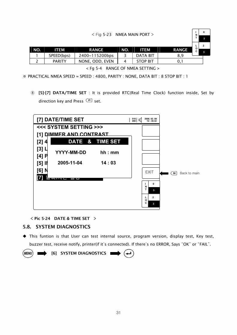
< Fig 5-23 NMEA MAIN PORT >
NO. ITEM RANGE NO. ITEM RANGE
1 SPEED(bps) 2400~115200bps 3 DATA BIT 8,9 2 PARITY NONE, ODD, EVEN 4 STOP BIT 0,1
< Fg 5-4 RANGE OF NMEA SETTING >
※ PRACTICAL NMEA SPEED = SPEED : 4800, PARITY : NONE, DATA BIT : 8 STOP BIT : 1
⑧ [5]-[7] DATA/TIME SET : It is provided RTC(Real Time Clock) function inside, Set by
direction key and Press set.
< Pic 5-24 DATE & TIME SET >
5.8. SYSTEM DIAGNOSTICS
This funtion is that User can test internal source, program version, display test, Key test,
buzzer test, receive notify, printer(if it’s connected). If there’s no ERROR, Says “OK” or “FAIL”.
[6] SYSTEM DIAGNOSTICS
I 0 N T L 2 O C 3
3
[7] DATE/TIME SET
<<< SYSTEM SETTING >>>
[1] DIMMER AND CONTRAST [2] 490/4209 SELECT [ 490 ] [3] LCD REVERSE [ OFF] [4] PRINTER SPEED
[5] INS SPEED
[6] NMEA SPEED
[7] 날짜/시간 설정
EXIT
In 0 Is 0 Ln 0Ls 0
DATE & TIME SET YYYY-MM-DD hh : mm
2005-11-04 14 : 03
Back to main
I 0 N T L 2 O C 3
3
[ 518 ] 2006. 02. 08[ 490 ] 12 : 30.32

32
< 그림 5-25 시스템 자가 진단 >
① [6]-[1] PROGRAM VERSION : It is showned current SNX-300 version. Press and move
to MAIN.
SNX-300
메인 메뉴 >>>
[1] STATION SELECTION [2] MESSAGE SELECTION [3] MESSAGE HISTORY [4] USER SETTING [5] SYSTEM SETTING [6] SYSTEM DIAGNOSTICS [7] FACT MANUAL
EXIT
In 0 Is 0 Ln 0Ls 0
메인메뉴로
SNX-300
<<< SYSTEM DIAGNOSTICS >>>
[1] PROGRAM VERSION [2] LCD TEST [3] KEY TEST [4] PRINTER TEST [5] BUZZER TEST
[6] SELF TEST
[7] RF RECEIVER TEST [8] ALARM
종료
In 0 Is 0 Ln 0Ls 0
I 0 N T L 2 O C 3
3
[6] 시스템 자가 진단
[ 518 ] 2006. 02. 08[ 490 ] 12 : 30.32
[ 518 ] 2006. 02. 08[ 490 ] 12 : 30.32
[1] PROGRAM VERSION
<<< SYSTEM DIAGNOSTICS >>>
[1] PROGRAM VERSION [2] 표시기 검사 [3] 키보드 입력 검사 [4] 프린터 출력 검사 [5] 부저음 출력 검사
[6] 자가 진단 시험
[7] 수신부 검사 [8] ALARM
In 0 Is 0 Ln 0Ls 0
SNX-300 PROGRAM VERSION
01.00 Ver
(01.00)
CONFIRM
I 0 N T L 2 O C 3
3
[ 518 ] 2006. 02. 08 [ 490 ] 12 : 30.32

33
< Pic 5-26 PROGRAM VERSION >
② [6]-[2] LCD TEST : Accoring to the screen Keep pressing until LCD TEST end, it can be
checked LCD status and back to MAIN.
< Pic 5-27 LCD TEST >
③ [6]-[3] KEY TEST : Push the keys then reversing the keys. Press four times then end
TEST and press .
[2] LCD TEST
<<< SYSTEM DIAGNOSTICS >>>
[1] PROGRAM VERSION [2] LCD TEST [3] KEY TEST력 검사 [4] PRINTER TEST출력 검사 [5] BUZZER TEST검사
[6] SELF TEST험
[7] RF RECEIVER TEST [8] ALARM
종료
In 0 Is 0 Ln 0Ls 0
LCD 320X240 TEST
ENTER KEY START
CONFIRM 메인화면으로
ENTER
LCD TEST END !!
ENT
6 TIME INPUT I 0 N T L 2 O C 3
3
[ 518 ] 2006. 02. 08[ 490 ] 12 : 30.32

34
< Fig 5-28 KEY TEST 1 >
4TIME CLICK, MOVE
TO
< Fig 5-29 KEY TEST 2 >
④ [6]-[4] 프린터 출력 검사 : 만약 프린터가 연결되어 있다면 키를 사용하여 프린터의 인쇄
상태를 시험할 수 있다.
SNX-300
<<< SYSTEM DIAGNOSTICS >>>
[1] PROGRAM VERSION [2] LCD TEST [3] KEY TEST [4] PRINTER TEST [5] BUZZER TEST
[6] SELF TEST 시험
[7] RF RECEIVER TEST [8] ALARM 상태 표시
In 0 Is 0 Ln 0Ls 0
4 TIMES CLICK
ENTER
KEY TEST END !!
CONFIRM
[3] 키보드 입력 검사
EXIT
In 0 Is 0 Ln 0 Ls 0
Samyung ENC
SNX-300
I 0 N T L 2 O C 3
3
[ 518 ] 2006. 02. 08[ 490 ] 12 : 30.32
[ 518 ] 2006. 02. 08 [ 490 ] 12 : 30.32

35
< Fig 5-30 PRINTOUT TEST >
⑤ [6]-[5] BUZZER TEST : Check the Buzzer. When it comes to get in BUZZER TEST, It sounds
“Bip” , Press then OFF. Press move to MAIN.
Back to main
SNX-300
<<< SYSTEM DIAGNOZTICS >>> [1] PROGRAM VERSION [2] LCD TEST [3] KEY TEST [4] PRINTER TEST [5] BUZZER TEST
[6] SELF TEST
[7] RF RECEIVER TEST [8] ALARM
In 0 Is 0 Ln 0Ls 0
[4] 프린터 출력 검사
EXIT
In 0 Is 0 Ln 0 Ls 0
EXTERNAL PRINTER TEST Samyung Navtex SNX300
PRINT TEST 1234567890&^%$##@!@*><{}
ABCDEFGHIJKLMNOPQRSTUVWXYZ
SYENC PRINT
I 0 N T L 2 O C 3
3
[ 518 ] 2006. 02. 08 [ 490 ] 12 : 30.32
[ 518 ] 2006. 02. 08[ 490 ] 12 : 30.32
[5] BUZZER TEST
<<< SYSTEM DIAGNOSTICS >>> [1] PROGRAM VERSION [2] LCD TEST [3] KEY TEST [4] PRINTER TEST [5] BUZZER TEST [6] SELF TEST [7] RF REEIVER TEST [8] ALARM
EXIT
In 0 Is 0 Ln 0Ls 0
BUZZER TEST
BUZZER OUTPUT STOP
CONFIRM Back to main
I 0 N T L 2 O C 3
3
[ 518 ] 2006. 02. 08[ 490 ] 12 : 30.32

36
< Fig 5-31 BUZZER TEST >
⑥ [6]-[6] SELF TEST : Press to check Memory & RF PCB status. If there’s ERROR, Says
“FAIL” and alarm instead “OK”. Initial screen Press off alarm sound.
< Pic 5-32 SELF TEST 1 >
< Pic 5-33 SELF TEST 2 >
⑦ [6]-[7] RF RECEIVER TEST : Check RF Receiver status by . What different from SELF
TEST is transmitting and receiving messages. If there’s ERROR, Says “FAIL”.
Back to main
[6] SELF TEST
<<< SYSTEM DIAGNOSTICS >>> [1] PROGRAM VERSION [2] LCD TEST [3] KEY TEST [4] PRINTER TEST [5] BUZZER TEST [6] SELF TEST [7] RF RECEIVER TEST [8]
EXIT
In 0 Is 0 Ln 0Ls 0
SELF TEST
ENTER KEY START
CONFIRM I 0 N T L 2 O C 3
3
[ 518 ] 2006. 02. 08[ 490 ] 12 : 30.32
[6] SELF TEST
<<< SYSTEM DIAGNOSTICS >>> [1] PROGRAM VERSION [2] LCD TEST [3] KEY TEST [4] PRINTER TEST [5] BUZZER TEST [6] SELF TEST [7] RF RECEIVER TEST [8]
EXIT
In 0 Is 0 Ln 0Ls 0
SELF TEST
MEMORY TEST…...OK
518CH TEST…….….OK
490CH TEST…….….OK
4209CH TEST…...…..OK
OK
Back to main
I 0 N T L 2 O C 3
3
[ 518 ] 2006. 02. 08[ 490 ] 12 : 30.32

37
< Pic 5-34 RF RECEIVER TEST 1 >
< Pic 5-35 RF RECEIVER TEST 2 >
⑧ [6]-[8] ALARM : It displays Alarm status and says [NO] in nomal state.
[YES] : in alarm state.
[STANDBY] : It says when it eliminate Alarm without solving following errors [RECEIVER
ERROR], [SELF TEST ERROR], [GENERAL ERROR].
Back to main
[7] RF RECEIVER TEST
<<< 시스템 자가 진단 >>> [1] PROGRAM VERSION [2] LCD TEST [3] KEY TEST [4] PRINTER TEST [5] BUZZER TEST [6] SELF TEST [7] RF RECEIVER TEST [8]
EXIT
In 0 Is 0 Ln 0Ls 0
RECEIVER TEST
ENTER KEY START
CONFIRM I 0 N T L 2 O C 3
3
[ 518 ] 2006. 02. 08[ 490 ] 12 : 30.32
[7] RF RECEIVER TEST
<<< SYSTEM DIAGNOSTICS >>> [1] PROGRAM VERSION [2] LCD TEST [3] KEY TEST [4] PRINTER TEST [5] BUZZER TEST [6] SELF TEST [7] RF RECEIVER TEST [8]
EXIT
In 0 Is 0 Ln 0Ls 0
RECEIVER TEST
518 TEST….OK
490 TEST….OK
4209 TEST….OK
4209 KHz
ABCDEFGHIJ KLMNOPQRS^
T UVWXYZ1234 567890??^
:., -()’=/+
NNNN
Back to main
I 0 N T L 2 O C 3
3
[ 518 ] 2006. 02. 08[ 490 ] 12 : 30.32

38
< Pic 5-36 ALARM >
[8] ALARM
ALARM : NAVIGATION ALERT [NO]
ALARM : WEATHER ALERT [YES]
ALARM : SEARCH AND RESCUE INFO [NO]
ALARM : RECEIVER ERROR [NO]
ALARM : SELF TEST FAIL [STANDBY]
ALARM : GENERAL FAIL [NO]
EXIT
In 0 Is 0 Ln 0Ls 0
I 0 N T L 2 O C 3
3
Back to main
[ 518 ] 2006. 02. 08[ 490 ] 12 : 30.32
39
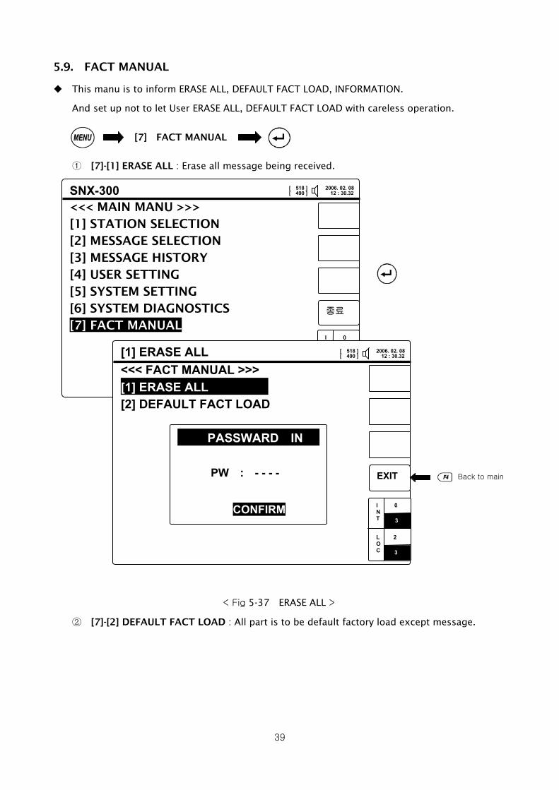
5.9. FACT MANUAL
This manu is to inform ERASE ALL, DEFAULT FACT LOAD, INFORMATION.
And set up not to let User ERASE ALL, DEFAULT FACT LOAD with careless operation.
① [7]-[1] ERASE ALL : Erase all message being received.
< Fig 5-37 ERASE ALL >
② [7]-[2] DEFAULT FACT LOAD : All part is to be default factory load except message.
[7] FACT MANUAL
SNX-300
<<< MAIN MANU >>> [1] STATION SELECTION [2] MESSAGE SELECTION [3] MESSAGE HISTORY [4] USER SETTING [5] SYSTEM SETTING [6] SYSTEM DIAGNOSTICS [7] FACT MANUAL
종료
In 0 Is 0 Ln 0Ls 0
Back to main
I 0 N T L 2 O C 3
3 [1] ERASE ALL
<<< FACT MANUAL >>>
[1] ERASE ALL [2] DEFAULT FACT LOAD
EXIT
In 0 Is 0 Ln 0 Ls 0
PASSWARD IN
PW : - - - -
CONFIRM I 0 N T L 2 O C 3
3
[ 518 ] 2006. 02. 08[ 490 ] 12 : 30.32
[ 518 ] 2006. 02. 08 [ 490 ] 12 : 30.32

40
Chapter 6. INSTALLATION & TROUBLSHOOTING
6.1. HOW TO INSTALL RECEIVER
You may install Navtex Receiver by using a mounting bracket, which is provided with Navtex
Receiver on the desk, shelf and ceiling and so on.
6.1.1. Installation Place
① Place where it is over 1 meter distance from Gyro Compass.
② Place where is enabling ground at a short distance.
③ Place where there is not allowed to expose directly by sunray and avoid from heating
element ad the place where there is of little vibration.
④ Place where main unit, antenna, PSU, earth cables etc. are as far as possible from
transmitter, radar’s cable.
⑤ Place where there is as far as possible from a fan and exhaust pipe and well-ventilated
place.
6.1.2. Installation Sequence and Method
① Dissemble the screws with the knob at both sides to install NAVTEX Receiver.
② Fix firmly a mounting bracket supplied with a Receiver on the desk or wall to be installed.
(Use screw.)
③ After NAVTEX Receiver is inserted into the mounting bracket, adjust the angles and spin
the screws with the knob of right and left for better adjustment.
41
342
단위 : mm
< Picture 6-1 Device Installations >
6.2. ANTENNA INSTALLATION
6.2.1. Installation Place
① It should be installed highly at the place where is not covered a wave by structures such
as mast, bridge and chimney and not be installed at the lower place than MF/HF wire
antenna.
② It should be installed vertically and at the place away from MF/HF transmitting antenna
and radar to prevent from bad sensitivity by noisy and receiver’s defect.
③ If there are various places that are able to install the antennas, it should be installed
temporary with connecting a receiver and found a most suitable place after check place
one by one.
6.2.2. Installation Sequence and Method
① Fix antenna on antenna tube supplied with the antenna from mast (φ23~φ43) by using
stain belt (φ40~φ64).
② After antenna cable is inserted inside, connect the cable ends to a connector.
6.3. TROUBLESHOOTING AND INSPECTION
The device must be handled with a care in order to keep better efficiency and validity. It
had better be periodical inspected for the best efficiency by an engineer.
Please keep DC 12 ~ 24V of device’s voltage rating.
Please pre-check out the condition of the consumed current in time of receiving or not
receiving, then compare the condition with one of the above-ordinary times when it has
defects and turn off the power of the device according to the situation.

42
No make persons to repair or break down the devices except Samyung’s engineers at A/S
department. It might take place an electronic shock, out of order of the device and wrong
operation. Please contact to an agent or A/S department in case of any defects on devices.
6.3.1. General Troubleshooting and Inspection
① Polish exterior of the device such as a keypad, LCD with soft fabric.
② Fasten firmly bolt, nut, a connector for antenna in case of a loose fit by using a driver.
③ Inspect printer papers at any time when it connects to a printer and uses it. It might
wrong print necessary information if the papers are lack. Replace the papers in case
of showing red lines in a printing paper.
④ In case of any defectiveness, please do not disassemble the equipment and contact
our distributor or our A/S center. (Refer to 6.4 Troubleshooting.)
6.3.2. Device Composition
The composition is as follows.
NO. COMPOSITION MODEL REMARK
1 Receiver PCB N-726
2 CPU PCB N-727
3 Key PCB N-728
4 Power supply SP-300AD OPTION
5 Printer DPU-414 OPTION
6 Antenna SAN-300
<Table 6-1 Scope of supply>
6.4. TROUBLE SHOOTING
It must not be inspected and repaired by persons except Samyung’s engineers. It might take place electronic shock, a fire, wrong-operation of a device if a not permitted person inspects devices. Contact to an agent or A/S dep. in case of showing wrong-operation in a device.
NO. DEFECT SYMPTOM DEFECT CAUSE SOLUTION
1 No power-on Power supply Check on power supply’s voltage
and cutting
WARNING

43
Fuse Check on fuse cutting
Key Board Check on PCB N-728
LCD connecting cable Check on LCD connection cable
Power supply Check on supply power into LCD
CPU PCB Check on PCB N-727
LCD Defective LCD
2 No power-on of LCD
screen
LCD luminosity Adjust brightness and luminosity
(Refer to 5.7)
Buzzer Buzzer is defective.
KEY PCB Check on PCB N-728
3 Alarm
CPU PCB Check on PCB N-727
NO. DEFECT SYMPTOM DEFECT CAUSE SOLUTION
Check on antenna polarity
Check on antenna cutting
Check on antenna position (Refer
to 6.2)
Check on broadcasting time
Antenna
Check on voltage of active
antenna (DC 8V)
Select a station and
message Refer to 5.3 & 5.4
Receiver PCB Check on PCB N-726
4 No receiving of
broadcasting
Main unit Check on main unit
Check on power voltage into
printer
5 Not operate a printer Power
Check on polarity & cutting of
power cable
Check on data cable
Check on printer port setting
(Refer to Chapter 5.7)
6 No print-out Check on data cable
Check printer paper
< Table 6-2 TROUBLE SHOOTING >

44
Chapter 7. AFTER-SALES SERVICE
7.1. GUARANTEE PERIOD
We guarantee a free-repair for a year from a purchased date. It should be charged in defects by
user’s inappropriate operation or modification at discretion.
7.2. DEVICES DISPOSAL
Please contact to our distributor or A/S centre to make a disposal of the devices in case of not
being used more for damage or the lifetime’s end
SERVICE CENTER DETAILS (HEAD OFFICE)
Address 65-20 2-Ga Namhang-Dong Youngdo-Gu Busan Korea
Department A/S Centre of SAMYUNG ENC Co., Ltd.
Phone +82-51-601-5570 / +82-51-601-5510
Fax +82-51-413-4446
You can get a prompt service if you advise phone number, operation conditions, serial
number, device name by fax, phone. Contact to our distributor in your area first!!

45
Contact for Sales & Service Distributor
Sales person
Office phone: Phone
Mobile:
Keep a phone number of a person on duty when you purchase devices!!!
CHAPTER 8. BROADCASTING TIMES OF
NEIGHBORING COUNTRIES

46
< Pic 8-1 NAVAREAS >
NAVTEX Broadcasting Times
NA
V
are
a
Country Station Latitud
e
Longitud
e
Frequenc
y
(KHz)
Rang
e
(nm)
I
D
Broadcast
schedule(UTC)

47
Oostende 518 50 T 0310, 0710, 1110, 1510, 1910,
2310 Belgium
Oostende(THAMES)
51 11 N 02 48 E
518 150 M 0200, 0600, 1000, 1400, 1800,
2200
Estonia Tallinn 59 30 N 24 30 E 518 300 U 0320, 0720, 1120, 1520, 1920,
2320
518 250 X 0350, 0750, 1150, 1550, 1950,
2350 Iceland Reykjavik 64 05 N 21 51 W
518 550 R 0250, 0650, 1050, 1450, 1950,
2350
Malin Head 55 22 N 07 21 W 518 400 Q 0240, 0640, 1040, 1440, 1840,
2240 Ireland
Valentia 51 27 N 09 49 W 518 400 W 0340, 0740, 1140, 1540, 1940,
2340
Netherland
s Den Helder 52 06 N 04 15 E 518 250 P
0230, 0630, 1030, 1430, 1830,
2230
Svalbard 78 04 N 13 38 E 518 450 A 0000, 0400, 0800, 1200, 1600,
2000
Bodo 67 16 N 14 23 E 518 450 B 0010, 0410, 0810, 1210, 1610,
2010
Rogaland 58 48 N 05 34 E 518 450 L 0150, 0550, 0950, 1350, 1750,
2150
Vardo 70 22 N 31 06 E 518 450 V 0300, 0700, 1100, 1500, 1900,
2300
Norway
Orlandet 63 40 N 09 33 E 518 450 N 0210, 0610, 1010, 1410, 1810,
2210
Bjuroklubb 64 28 N 21 36 E 518 300 H 0010, 0410, 0810, 1210, 1610,
2010
Gislovhammar 55 29 N 14 19 E 518 300 J 0130, 0530, 0930, 1330, 1730,
2130 Sweden
Grimeton 57 06 N 12 23 E 518 300 D 0030, 0430, 0830, 1230, 1630,
2030
518 270 O 0220, 0620, 1020, 1420, 1820,
2220 Portpatrick 54 51 N 05 07 W
490 270 C 0020, 0420, 0820, 1220, 1620,
2020
518 270 G 0100, 0500, 0900, 1300, 1700,
2100 Cullercoats 55 02 N 01 26 W
490 270 U 0320, 0720, 1120, 1520, 1920,
2320
518 270 E 0040, 0440, 0840, 1240, 1640,
2040
I
United
Kingdom
Niton 50 35 N 01 18 W
490 270 I 0120, 0520, 0920, 1320, 1720,
2120
490 300 E 0040, 0440, 0840, 1240, 1640,
2040 France Corsen 48 28 N 05 03 W
518 300 A 0000, 0400, 0800, 1200, 1600,
2000
II
Portugal Horta 38 32 N 28 38 W 490 640 J 0130, 0530, 0930, 1330, 1730,
2130
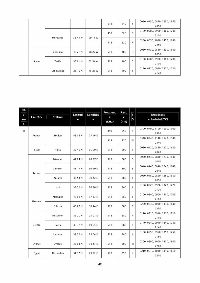
48
518 640 F 0050, 0450, 0850, 1250, 1650,
2050
490 520 G 0100, 0500, 0900, 1300, 1700,
2100 Monsanto 38 44 W 09 11 W
518 520 R 0250, 0650, 1050, 1450, 1850,
2250
Corunna 43 21 N 08 27 W 518 400 D 0030, 0430, 0830, 1230, 1630,
2030
Tarifa 36 01 N 05 34 W 518 400 G 0100, 0500, 0900, 1300, 1700,
2100 Spain
Las Palmas 28 10 N 15 25 W 518 400 I 0120, 0520, 0920, 1320, 1720,
2120
NA
V
are
a
Country Station Latitud
e
Longitud
e
Frequenc
e
(KHz)
Rang
e
(nm)
I
D
Broadcast
schedule(UTC)
490 250 S 0300, 0700, 1100, 1500, 1900,
2300 France Toulon 43 06 N 27 46 E
518 250 W 0340, 0740, 1140, 1540, 1940,
2340
Israel Haifa 32 49 N 35 00 E 518 200 P 0020, 0420, 0820, 1220, 1620,
2020
Istanbul 41 04 N 28 57 E 518 300 D 0030, 0430, 0830, 1230, 1630,
2030
Samsun 41 17 N 36 20 E 518 300 E 0040, 0440, 0840, 1240, 1640,
2040
Antalya 36 53 N 30 42 E 518 300 F 0050, 0450, 0850, 1250, 1650,
2050
Turkey
Izmir 38 22 N 26 36 E 518 300 I 0120, 0520, 0920, 1320, 1720,
2120
Mariupol 47 06 N 37 33 E 518 280 B 0100, 0500, 0900, 1300, 1700,
2100 Ukraine
Odessa 46 29 N 30 44 E 518 280 C 0230, 0630, 1030, 1430, 1830,
2230
Heraklion 35 20 N 25 07 E 518 280 H 0110, 0510, 0910, 1310, 1710,
2110
Corfu 39 37 N 19 55 E 518 280 K 0140, 0540, 0940, 1340, 1740,
2140 Greece
Lemnos 39 52 N 25 04 E 518 280 L 0150, 0550, 0950, 1350, 1750,
2150
Cyprus Cyprus 35 03 N 33 17 E 518 200 M 0200, 0600, 1000, 1400, 1800,
2200
III
Egypt Alexandria 31 12 N 29 52 E 518 350 N 0210, 0610, 1010, 1410, 1810,
2210

49
Malta Malta 35 49 N 14 32 E 518 400 O 0220, 0620, 1020, 1420, 1820,
2220
Croatia Split 43 30 N 16 29 E 518 85 Q 0240, 0640, 1040, 1440, 1840,
2240
Rome 41 48 N 12 31 W 518 320 R 0250, 0650, 1050, 1450, 1850,
2250
Cagliari 39 14 N 09 14 E 518 320 T 0310, 0710, 1110, 1510, 1910,
2310
Trieste 45 41 N 13 46 E 518 320 U 0320, 0720, 1120, 1520, 1920,
2320
Italy
Augusta 37 14 N 15 14 E 518 320 V 0330, 0730, 1130, 1530, 1930,
2330
Russia Novorossiysk 44 42 N 37 44 E 518 300 A 0300, 0700, 1100, 1500, 1900,
2300
Spain Cabo de la Nao 38 43 N 00 09 E 518 300 X 0350, 0750, 1150, 1550, 1950,
2350
490 300 S 0310, 0710, 1110, 1510, 1910,
2310 Iqaluit 63 43 N 68 33 W
518 300 T 0320, 0720, 1120, 1520, 1920,
2320
518 300 C 0020, 0420, 0820, 1220, 1620,
2020 Riviere-au-Renard 50 11 N 66 07 W
518 300 D 0035, 0435, 0835, 1235, 1635,
2035
Wiarton 44 20 N 81 10 W 518 300 H 0110, 0510, 0910, 1310, 1710,
2110
St. Johns 47 30 N 52 40 W 518 300 O 0220, 0620, 1020, 1420, 1820,
2220
Thunder Bay 48 25 N 89 20 W 518 300 P 0230, 0630, 1030, 1430, 1830,
2230
518 300 Q 0240, 0640, 1040, 1440, 1840,
2240 Sydney 46 10 N 60 00 W
518 300 J 0255, 0655, 1055, 1455, 1855,
2255
518 300 U 0320, 0720, 1120, 1520, 1920,
2320 Fundy 43 45 N 66 10 W
518 300 V 0335, 0735, 1135, 1535, 1935,
2235
Canada
Labrador 53 42 N 57 01 W 518 300 X 0350, 0750, 1150, 1550, 1950,
2350
IV
USA Miami 25 37 N 80 23 W 518 240 A 0000, 0400, 0800, 1200, 1600,
2000

50
NA
V
are
a
Country Station Latitud
e
Longitud
e
Frequenc
e
(KHz)
Rang
e
(nm)
I
D
Broadcast
schedule(UTC)
Savannah 32 08 N 81 42 W 518 200 E 0040, 0440, 0840, 1240, 1640,
2040
Boston 41 43 N 70 30 W 518 200 F 0045, 0445, 0845, 1245, 1645,
2045
New Orleans 29 53 N 89 57 W 518 200 G 0300, 0700, 1100, 1500, 1900,
2300
Portsmouth 36 43 N 76 00 W 518 280 N 0130, 0530, 0930, 1330, 1730,
2130
USA
San Juan 18 28 N 67 04 W 518 200 R 0200, 0600, 1000, 1400, 1800,
2200
Dutch
Antilles Curacao 12 10 N 68 52 W 518 400 H
0110, 0510, 0910, 1310, 1710,
2110
IV
Bermuda Bermuda 32 23 N 64 41 W 518 280 B 0010, 0510, 0910, 1310, 1710,
2110
V -
Ushaia 54 48 S 68 18 W 518 280 M 0200, 0600, 1000, 1400, 1800,
2200
Rio Gallegos 51 37 S 65 03 W 518 280 N 0210, 0610, 1010, 1410, 1810,
2210
Comodoro
Rivadavia 45 51 S 67 25 W 518 280 O
0220, 0620, 1020, 1420, 1820,
2220
Bahia Blanca 38 43 S 62 06 W 518 280 P 0230, 0630, 1030, 1430, 1830,
2230
Mar del Plata 38 03 S 57 32 W 518 280 Q 0240, 0640, 1040, 1440, 1840,
2240
Argentina
Buenos Aires 34 36 S 58 22 W 518 560 R 0250, 0650, 1050, 1450, 1850,
2250
518 280 F 0050, 0450, 0850, 1250, 1650,
2050
VI
Uruguay La Paloma 34 40 S 54 09 W
490 280 A 0000, 0400, 0800, 1200, 1600,
2000
Namibia Walvis Bay 23 03 S 14 37 E 518 380 B 0010, 0410, 0810, 1210, 1610,
2010
Cape Town 33 40 S 18 43 E 518 500 C 0020, 0420, 0820, 1220, 1620,
2020
Port Elizabeth 34 02 S 25 33 E 518 500 I 0120, 0520, 0920, 1320, 1720,
2120
VII South
Africa
Durban 30 00 S 31 30 E 518 500 O 0220, 0620, 1020, 1420, 1820,
2220
Mumbay 19 05 N 72 50 E 518 250 G 0100, 0500, 0900, 1300, 1700,
2100 India
Madras 13 08 N 80 10 E 518 250 P 0230, 0630, 1030, 1430, 1830,
2230 VIII
Mauritius Mauritius Radio 20 10 S 57 28 E 518 400 C 0020, 0420, 0820, 1220, 1620,
2020

51
Bahrain Hamala 26 09 N 50 28 E 518 300 B 0010, 0410, 0810, 1210, 1610,
2010
518 200 X 0350, 0750, 1150, 1550, 1950,
2350 Serapeum 30 28 N 32 22 E
4209.5 200 X 0750, 1150 Egypt
Kosseir 26 06 N 34 17 E 518 400 V 0330, 0730, 1130, 1530, 1930,
2330
Bushehr 28 59 N 50 50 E 518 300 A 0000, 0400, 0800, 1200, 1600,
2000 Iran
Bandar Abbas 27 07 N 56 04 E 518 300 F 0050, 0450, 0850, 1250, 1650,
2050
Saudi
Arabia Jeddah 21 23 N 39 10 E 518 390 H 0705, 1305, 1905
Oman Muscat 23 36 N 58 30 E 518 270 M 0200, 0600, 1000, 1400, 1800,
2200
IX
Pakistan Karachi 24 51 N 67 03 E 518 400 P 0230, 0630, 1030, 1430, 1830,
2230
NA
V
are
a
Country Station Latitud
e
Longitud
e
Frequenc
e
(KHz)
Rang
e
(nm)
I
D
Broadcast
schedule(UTC)
X -
490 200 J 0130, 0530, 0930, 1330, 1730,
2130 Chukpyong 37 03 N 129 26 E
518 200 V 0330, 0730, 1130, 1530, 1930,
2330
490 200 K 0140, 0540, 0940, 1340, 1740,
2140
Republic of
Korea
Pyongsan 35 36 N 126 29 E
518 200 W 0340, 0740, 1140, 1540, 1940,
2340
Otaru 43 19 N 140 27 E 518 400 J 0130, 0530, 0930, 1330, 1730,
2130
Kushiro 42 57 N 144 36 E 518 400 K 0140, 0540, 0940, 1340, 1740,
2140
Yokohama 35 14 N 139 55 E 518 400 I 0120, 0520, 0920, 1320, 1720,
2120
Moji 34 01 N 130 56 E 518 400 H 0110, 0510, 0910, 1310, 1710,
2110
Japan
Naha 26 05 N 127 40 E 518 400 G 0100, 0500, 0900, 1300, 1700,
2100,
Sanya 18 14 N 109 30 E 518 250 M 0200, 0600, 1000, 1400, 2200
Guangzhou 23 08 N 113 32 E 518 250 N 0210, 0610, 1010, 1410, 2210
Fuzhou 26 01 N 119 18 E 518 250 O 0220, 0620, 1020, 1420, 2220
Shanghai 31 08 N 121 33 E 518 250 Q 0240, 0640, 1040, 1440, 2240
XI
China
Dalian 38 52 N 121 31 E 518 250 R 0250, 0650, 1050, 1450, 2250

52
Jayapura 02 31 S 140 43 E 518 300 A 0000, 0400, 0800, 1200, 1600,
2000
Ambon 03 42 S 128 12 E 518 300 B 0010, 0410, 0810, 1210, 1610,
2010
Makassar 05 06 S 119 26 E 518 300 D 0030, 0430, 0830, 1230, 1630,
2030
Indonesia
Jakarta 06 06 S 106 54 E 518 300 E 0040, 0440, 0840, 1240, 1640,
2040
Penang 05 26 N 100 24 E 518 350 U 0320, 0720, 1120, 1520, 1920,
2320
Miri 04 28 N 114 01 E 518 350 T 0310, 0710, 1110, 1510, 1910,
2310 Malaysia
Sandaken 05 54 N 118 00 E 518 350 S 0300, 0700, 1100, 1500, 1900,
2300
Singapore Singapore 01 25 N 103 52 E 518 400 C 0020, 0420, 0820, 1220, 1620,
2020
Thailand Bangkok 13 43 N 100 34 E 518 200 F 0050, 0450, 0850, 1250
Ho Chi Minh 10 47 N 106 40 E 518 400 X 0350, 0750, 1150, 1550, 1950,
2350
490 400 W 0340, 1540
Haiphong 20 44 N 106 44 E 4209.5 400 W
0230, 0630, 1030, 1430, 1830,
2230
Vietnam
Da nang 16 05 N 108 13 E 518 400 K 0140, 0540, 0940, 1340, 1740,
2140
Taiwan Kaohsiung 22 29 N 120 25 E 518 400 P 0230, 0630, 1030, 1430, 1830,
2230
USA Guam 13 29 N 144 50 E 518 100 V 0100, 0500, 0900, 1300, 1700,
2100
NA
V
are
a
Country Station Latitud
e
Longitud
e
Frequenc
e
(KHz)
Rang
e
(nm)
I
D
Broadcast
schedule(UTC)
Prince Rupert 54 20 N 130 20 W 518 300 D 0030, 0430, 0830, 1230, 1630,
2030 Canada
Tofino 48 55 N 125 35 W 518 300 H 0110, 0510, 0910, 1310, 1710,
2110
San Francisco 37 55 N 122 44 W 518 350 C 0400, 0800, 1200, 1600, 2000,
2400
Kodiak 57 46 N 152 34 W 518 200 J 0300, 0700, 1100, 1500, 1900,
2300
XII
USA
Honolulu 21 22 N 158 09 W 518 350 O 0040, 0440, 0840, 1240, 1640,
2040

53
Cambria 35 31 N 121 03 W 518 350 Q 0445, 0845, 1245, 1645, 2045,
0045
Astoria 46 10 N 123 49 W 518 216 W 0130, 0530, 0930, 1330, 1730,
2130
Kholmsk 47 02 N 142 03 E 518 300 B 0010, 0410, 0810, 1210, 1610,
2010
Murmansk 68 46 N 32 58 E 518 300 C 0020, 0420, 0820, 1250, 1650,
2050
Arkhangelsk 64 51 N 40 17 E 518 300 F 0050, 0450, 0850, 1250, 1650,
2050
XIII Russia
Astrakhan 45 47 N 47 33 E 518 250 W 0340, 0740, 1140, 1540, 1940,
2340
XIV -
Antofagasta 23 40 S 70 25 W 518 300 A
H
0400, 1200, 2000
0000, 0800, 1600
Valparaiso 32 48 S 71 29 W 518 300 B
I
0410, 1210, 2010
0010, 0810, 1610
Talcahuano 36 42 S 73 06 W 518 300 C
J
0420, 1220, 2020
0020, 0820, 1620
Puerto Montt 41 30 S 72 58 W 518 300 D
K
0430, 1230, 2030
0030, 0830, 1630
Punta Arenas 53 09 S 70 58 W 518 300 E
L
0440, 1240, 2040
0040, 0840, 1640
XV Chile
Isla de Pascua 27 09 S 109 25 W 518 300 F
G
0450, 1250, 2050
0050, 0850, 1650
Paita 518 200 S 0300, 0700, 1100, 1500, 1900,
2300
Callao 518 200 U 0320, 0720, 1120, 1520, 1920,
2320 XVI Peru
Mollendo 518 200 W 0340, 0740, 1140, 1540, 1940,
2340

54
CHAPTER 9. IEC 61162 Message Composition
9.1. NRX & NRM
C.1 NRX – NAVTEX received message
The NRX sentence is used to transfer the contents of a received NAVTEX message from the
NAVTEX receiver to another device. As the length of a single NAVTEX message may exceed the
number of characters permitted in a single NMEA 0183 sentence, many NRX sentences may be
required to transfer a single NAVTEX message.
$--NRX,xxx,xxx,xx,aaxx,x,hhmmss.ss,xx,xx,xxxx,x.x,x.x,A,c--c*hh<CR><LF>
message body 7
status indication 6
total number of bad characters
total number of characters in this
series of NRX sentences 5
year
month 1-12
day 1-31
UTC of receipt of message
frequency table index 0-9 4
NAVTEX message code 3
sequential message id 00-99 2
sentence number 001-999
number of sentences 001-999 1
NOTE 1 The total number of sentences required to transfer the NAVTEX message from the
NAVTEX radio receiver.
The first field specifies the total number of sentences used for a message, minimum value 1. The
Sentence Number field identifies the order of this sentence in the message, minimum value 1. All
sentences contain the same number of fields. For efficiency it is recommended that null fields be
used in the additional sentences where the data is unchanged from the first sentence (this applies
to fields 4 through 12).
NOTE 2 The sequential message identifier provides a unique identifier for each NAVTEX message
represented by a group of sentences. Though the message code (field 4) contains a NAVTEX
message serial number, there are special cases when the message serial number is set to 00 and

55
has a different meaning or when the same message code can occur more than once. When these
conditions occur, the sequential message identifier can be relied upon to uniquely identify this
NAVTEX message from other NAVTEX messages with the same message code.
NOTE 3 The NAVTEX message code contains three related entities. The first character identifies
the transmitter coverage area and the second character identifies the type of message. Both these
characters are as defined in Table I of Recommendation ITU-R M.625-3, combination numbers 1-
26. Transmitter identification characters are allocated by the IMO NAVTEX Co-ordinating Panel;
these characters and the meanings of the message type characters are described in the NAVTEX
manual (IMO publication 951E). The remaining two characters are restricted to numerals with a
range of 00 to 99 and represent a serial number for each type of message. The value of 00 is a
special case and not considered a serial number. See 4.3.5 for interpretation of special case value
of 00.
NOTE 4 The frequency indicator identifies the frequency that the NAVTEX message was received
on:
0 = not received over air (eg test messages)
1 = 490 kHz
2 = 518 kHz
3 = 4209,5 kHz
4 through 9 are reserved for future use
NOTE 5 The total number of characters indicates the expected size of the message body sent in
this sequence of NRX sentences. It does not include the additional overhead for reserved
characters found in table 1 of this IEC 61162-1.
NOTE 6 Status ‘A’ is used for syntactically correct message reception. Status ‘V’ is used for
syntactically incorrect message reception, e.g. end characters NNNN missing.
NOTE 7 The message body may contain reserved characters as defined in IEC 61162-1.

56
The example below shows a typical message received by the Navtex receiver with 3 bad
characters (‘*’):
<start of example>
ZCZC IE69==================================
ISSUED ON SATURDAY 06 JANUARY 2001.
INSHORE WATERS FORECAST TO 12 MILES
OFFSHORE FROM 1700 UT* TO 0500 UTC.
NORTH FORELAND TO SE**EY BILL.
12 HOURS FORECAST:
SHOWERY WINDS, STRONGEST IN NORTH.
NNNN
<end of example>
Inspecting the corresponding NRX sentences would typically show:
$CRNRX,007,001,00,IE69,1,135600,27,06,2001,241,3,A,==========================*09
$CRNRX,007,002,00,,,,,,,,,,========^0D^0AISSUED ON SATURDAY 06 JANUARY 2001.*29
$CRNRX,007,003,00,,,,,,,,,,^0D^0AINSHORE WATERS FORECAST TO 12 MILES^0D^0AOFF*0D
$CRNRX,007,004,00,,,,,,,,,,SHORE FROM 1700 UT^2A TO 0500 UTC.^0D^0A^0D^0ANORT*70
$CRNRX,007,005,00,,,,,,,,,,H FORELAND TO SE^2A^2AEY BILL.^0D^0A12 HOURS FOREC*16
$CRNRX,007,006,00,,,,,,,,,,AST:^0D^0A^0ASHOWERY WINDS^2C STRONGEST IN NORTH.^0D*15
$CRNRX,007,007,00,,,,,,,,,,^0A^0A*79
Decoding the message body should give the following result:
<start of decoding>
==================================
ISSUED ON SATURDAY 06 JANUARY 2001.
INSHORE WATERS FORECAST TO 12 MILES
OFFSHORE FROM 1700 UT* TO 0500 UTC.
NORTH FORELAND TO SE**EY BILL.
12 HOURS FORECAST:
SHOWERY WINDS, STRONGEST IN NORTH.
<end of decoding>

57
C.2 NRM – NAVTEX receiver mask
This command is used to manipulate the configuration masks that control which messages are
stored, printed and sent to the INS port of the NAVTEX receiver.
$--NRM,x,x,hhhhhhhh,hhhhhhhh*hh<CR><LF>
message type mask 4
transmitter coverage area mask 3
frequency table index 2, 1 to 9
function code 1, 0 to 9
NOTE 1 The function code is used to further identify the purpose of the sentence. The meaning of
the function code is as follows:
0 – request messages for the given mask
1 – set/report the storage mask
2 – set/report the printer mask
3 – set/report the INS mask
4 to 9 – reserved for future use
NOTE 2 The frequency indicator identifies the frequency that the NAVTEX message was received
on:
1 = 490 kHz
2 = 518 kHz
3 = 4209,5 kHz
4 through 9 are reserved for future use
NOTE 3 The transmitter coverage area mask is defined as a 32 bit hex field where the least
significant bit represents transmitter coverage area ‘A’, the next bit is ‘B’ and so on up to bit 25
which is ‘Z’. Bits 31 through 26 are reserved for future use and are set to zero. To select a
transmitter coverage area, its corresponding bit should be set to one. To deselect a transmitter
coverage area its corresponding bit should be set to zero.
NOTE 4 The message type mask is defined as a 32 bit hex field where the least significant bit
represents message type ‘A’, the next bit is ‘B’ and so on up to bit 25 which is ‘Z’. Bits 31 through
26 are reserved for future use and are set to zero. To select a message type its corresponding bit
should be set to one. To deselect a message type its corresponding bit should be set to zero.

58
When another device (for example an INS) wishes to set one or more of the bit masks it sends one
or more NRM sentences to the NAVTEX receiver. When another device wishes to determine the
current values of the bit masks it sends a query sentence to the NAVTEX receiver as follows:
$--CRQ,NRM*hh<CR><LF>
On receiving this query, the NAVTEX receiver will respond with one NRM sentences for each mask
type and frequency combination that it supports. For example, a NAVTEX receiver which supports
separate storage, printer and INS masks for each of three receiver requencies will
return a total of nine NRM sentences in response to the above query.
Example usage:
$INNRM,2,1,00001E1F,00000023*57
This example specifies that message identifiers ‘A’, ‘B’ and ‘F’, received from transmitter areas ‘A’
to ‘E’ and ‘J’ to ‘M’ on 490 kHz should be sent to the printer port when they are received. Note that
this command sets the printer mask for future use; there is no immediate output generated as a
result of receiving this command.
Example usage:
$INNRM,0,2,00001E1F,0FFFFFFF*21
This example requests that all currently stored messages of all message types, received from
transmitter areas ‘A’ to ‘E’ and ‘J’ to ‘M’ on 518 kHz should be immediately returned to the
requesting device as a series of NRX sentences. Note that this command does not update any of
the stored masks.
9.2. INS SIGNAL
This equipment can receive navigation data in IEC 61162-1 Ed2/2 format.
① Switchover to 4.2095MHz $PSYCNF,4209
② Switchover to 490KHz $PSYCNF,490
③ Stop ALARM $__ACK,001* $__ACK,002* $__ACK,003* $__ACK,004* $__ACK,005* $__ACK,006*

59
CHAPTER 10. PACKING LIST
NAVTEX SNX-300 (STANDARD)
NO ITEM DESCRIPTION MODEL Q’TY CH REMARK
SNX-300 1 MAIN UNIT
CODE NO. SNX-300
1
SAN-300 2
ANTENNA
& BAR CODE NO. SAN-300 1
STAINLESS BAND 3 STAINLESS BAND
CODE NO. SNX-202 2
RG58C/U Ø5 4 ANT CABLE
CODE NO. SNX-301 1 A-02
TNC-BNC
15 M
CVV-SB 3C 0.75SQ 5
DC POWER
CABLE CODE NO. SNX-302 1 A-01 3 M
U/L 14 번 3.5 ㎟ 6 GROUND CABLE
CODE NO. SNX-205 1 A-04 1 M
250V/3A(20mm) 7 MAIN FUSE
20
CODE NO. SNX-303 2
Ø5 × 19mm 8 STEEL PIECE
CODE NO. SNX-308 10
SNX-300
Fixed
SNX-300-MK 9
INSTRUCTION
MANUAL
CODE NO. SNX-310 1

60
NAVTEX SNX-300 (OPTION)
NO ITEM DESCRIPTION MODEL Q’TY CH REMARK
SP-300AD 1 POWER SUPPLY O U T
SP-300AD PO W ER SU PPLY
PO W ER
220V
D CAC
O N
FU SE
5A
FU SE
1A
IN D IC ATO RD CAC
CODE NO. SP-300AD 1
CVV-SB 2C 2SQ 2
AC POWER CABLE
CODE NO. SNX-330 1 3M
CVV-SB 2C 2SQ 3
DC POWER CABLE CODE NO. SNX-331
1 3M
Ø4 × 19mm 4
STAINLESS PIECE CODE NO. SNX-332
4 SP-300AD
FIXED
250V/2A(20mm) 5
FUSE FOR AC POWER SUPPLY
20
CODE NO. SNX-304 2
250V/5A(20mm) 6
FUSE FOR DC POWER SUPPLY
20
CODE NO. SNX-305
2
DPU-414 7 PRINTER
CODE NO. DPU-414 1
8
CABLE FOR PRINTER CODE NO. SNX-333
1 A-05 1.5M
PRINTER CABLE 9 PRINTER CABLE
CODE NO. SNX-310 1 A-03 2M

61
CHAPTER 11. DPU-414 SETTING
※ How to set up DPU-414 4800BPS
전원 ON과 동시에 [ONLINE] 버튼을 약 2초간 누르면, 설정되어있는 DIP 스위치 세팅 모드를 출력합
니다. 현재 DIP 스위치 세팅을 출력한 후 다음과 같이 세팅을 계속 할 것인지를 묻는다. 스위치 세팅
모드에서 [ON-LINE]은 “ON”, [FEED]는 “OFF”를 의미합니다.
“Continue ? : Push “On-line SW”
“Write ? : Push “Paper feed SW” 가 출력된다.
① [ONLINE] 버튼을 누릅니다.
② “Dip SW-1”이 출력된다.
③ [FEED] 버튼을 누른다. “1 (OFF) : Input = Serial” 출력
④ [ON-LINE] 버튼을 누른다. “2 (ON ) : Printing Speed = High” 출력
⑤ [ON-LINE] 버튼을 누른다. “3 (ON ) : Auto Loading = ON” 출력
⑥ [FEED] 버튼을 누른다. “4 (OFF) : Auto LF = OFF” 출력
⑦ [ON-LINE] 버튼을 누른다. “5 (ON ) : Setting Command = Enable” 출력
⑧ [FEED] 버튼을 누른다. “6 (OFF) : Printing” 출력
⑨ [ON-LINE] 버튼을 누른다. “7 (ON ) : Density” 출력
⑩ [ON-LINE] 버튼을 누른다. “8 (ON ) : 100%” 출력
“Continue ? : Push “On-line SW”
“Write ? : Push “Paper feed SW” 가 출력된다.
① [ONLINE] 버튼을 누릅니다.
② “Dip SW-2”가 출력된다.
③ [ON-LINE] 버튼을 누른다. “1 (ON ) : Printing Columns = 40” 출력
④ [ON-LINE] 버튼을 누른다. “2 (ON ) : User Font Back-up = ON” 출력
⑤ [ON-LINE] 버튼을 누른다. “3 (ON ) : Character Select = Normal” 출력
⑥ [ON-LINE] 버튼을 누른다. “4 (ON ) : Zero = Normal” 출력
⑦ [ON-LINE] 버튼을 누른다. “5 (ON ) : International” 출력
⑧ [ON-LINE] 버튼을 누른다. “6 (ON ) : Character” 출력
⑨ [FEED] 버튼을 누른다. “7 (OFF) : Set” 출력
⑩ [FEED] 버튼을 누른다. “8 (OFF) : = England” 출력
“Continue ? : Push “On-line SW”
“Write ? : Push “Paper feed SW” 가 출력된다.
① [ONLINE] 버튼을 누릅니다.
② “Dip SW-3”이 출력된다.
③ [ON-LINE] 버튼을 누른다. “1 (ON ) : Data Length = 8 bits” 출력
④ [ON-LINE] 버튼을 누른다. “2 (ON ) : Parity Setting = No” 출력
⑤ [ON-LINE] 버튼을 누른다. “3 (ON ) : Parity Condition = Odd” 출력
⑥ [FEED] 버튼을 누른다. “4 (OFF) : Busy Control = XON / XOFF” 출력

62
⑦ [ON-LINE] 버튼을 누른다. “5 (ON ) : Baud” 출력
⑧ [FEED] 버튼을 누른다. “6 (OFF) : Rate” 출력
⑨ [FEED] 버튼을 누른다. “7 (OFF) : Select” 출력
⑩ [FEED] 버튼을 누른다. “8 (OFF) : 4800 bps” 출력
“Continue ? : Push “On-line SW”
“Write ? : Push “Paper feed SW” 가 출력된다.
[FEED] 버튼을 누르면, 세팅이 완료되고 다음과 같이 출력된다.
“DIP SW setting complete”
설정된 DIP 스위치 세팅을 확인하기 위해서는 전원 ON과 동시에 [ONLINE] 버튼을 약 2초간 누릅니다.
다음과 같이 출력되면, 4800bps로 정상 세팅 되었음을 의미합니다.
[ DIP SW setting mode ]
Dip SW-1
1 (OFF) : Input = Serial
2 (ON ) : Printing Speed = High
3 (ON ) : Auto Loading = ON
4 (OFF) : Auto LF = OFF
5 (ON ) : Setting Command = Enable
6 (OFF) : Printing
7 (ON ) : Density
8 (ON ) : = 100%
Dip SW-2
1 (ON ) : Printing Columns = 40
2 (ON ) : User Font Back-up = ON
3 (ON ) : Character Select = Normal
4 (ON ) : Zero = Normal
5 (ON ) : International
6 (ON ) : Character
7 (OFF) : Set
8 (OFF) : = England
Dip SW-3
1 (ON ) : Data Length = 8bits
2 (ON ) : Parity Setting = No
3 (ON ) : Parity Condition = Odd
4 (OFF) : Busy Control = XON / XOFF
5 (ON ) : Baud
6 (OFF) : Rate
7 (OFF) : Select
8 (OFF) : = 4800 bps
“Continue ? : Push “On-line SW”
“Write ? : Push “Paper feed SW” 가 출력된다.
※ 기기가 정상적으로 세팅이 되었으면, [FEED] 버튼을 눌러 DIP SW Setting mode에서 나간다.
만약, 정상적으로 세팅이 되지 않았다면, [ON-LINE] 버튼을 눌러 DIP SW를 다시 세팅합니다.

63
CHAPTER 12. CIRCUIT DIAGRAM

64
CHAPTER 13. EXTERNAL DIAGRAM