Embed Size (px)
Citation preview
NCSEA CODE ADVISORY SUB-COMMITTEE General Engineering, Loads and Materials
Meeting Agenda
Date: Friday - June 29, 2007 9:00 a.m. – 5:00 p.m. Location: The Hampton Inn at O'Hare Airport 3939 N Mannheim Road, Schiller Park, IL 60176 - 847-671-1700 Invited Attendees: CAC Committee Members Industry Liaisons Ed Huston Bonnie Manley John Grenier Jim Messersmith John Hutton Jason Thompson Joe Kallaby David Tyree Steve Kerr Bill Kussro Al Perry
1) Results of the May 2007, IBC Final Action Hearings in Rochester, NY a. Issues that we may want to reconsider or that will resurface.
i. FS 185, FS 186 & FS 196 Aggregate and gravel on roofs ii. G 73 Hardening of Exit stairs iii. S 5 Disproportionate collapse (see attached AHJCSI language) iv. S 9 & S 10 Deck and balcony live loads v. S 58 & S60 Removal of masonry provisions vi. S 66 Metal press plate trusses – remove sealing language
2) Discuss potential Code Change Proposals for next cycle
a. Present issues for research and development of future Code Change Proposals. i. Definition of canopies, awnings and marquees ii. Frost protection for equipment foundations iii. Load combinations including effects of cranes iv. Concentrated load requirements for roofs v. Deflection limits and other serviceability issues vi. A consideration of pile load tests vii. Further discussion about plywood protection for wind-borne debris viii. Wood trusses, OWSJ, and steel trusses (assign a subcommittee to address this) ix. Steel truss engineering requirements x. Discussion about the rewrite of chapter 18 xi. An update on Masonry lap splices xii. Two simplified wind proposals (attachments 2 & 3) xiii. Floor live loads at residential corridors (attachment 4) xiv. Floor live load reductions alternate method #1 percentage limits (attachment 4) xv. Floor live load reductions alternate method one-way slabs, etc. (attachment 4) xvi. Floor live load reductions of 100 psf (attachment 4) xvii. Floor live load reductions basic vs. alternate method (attachment 4) xviii. Floor live load reductions, basic vs. alternate method - technical issues (attachment 4) xix. Roof live load reductions (attachment 4) xx. Vehicle barrier systems (attachment 4) xxi. Roof planters as dead load or live load (attachment 4) xxii. Roof live loads -roof gardens, promenade, assembly, special purposes (attachment 4) xxiii. Load combinations at occupied roofs (attachment 4) xxiv. Partitions as dead load or live load (attachment 4) xxv. Reductions in partition live loads (attachment 4) xxvi. Retaining walls and nonseismic surcharges (attachment 4) xxvii. Hazardous materials and occupancy category (attachment 4) xxviii. Mean roof height (attachment 4)
Code Advisory General Engineering Sub-Committee Meeting Agenda – June 29, 2007 Page 2
xxix. Parts versus portions (attachment 4) xxx. Restrictions, posting and changes in design loads (attachment 4) xxxi. Shower seats and dressing room bench seats (attachment 4) xxxii. 1607.6 Truck and bus garages (attachment 5) xxxiii. CCP on cantilever deck loading for uplift 1604.8.3 (attachment 6) xxxiv. Jurisdictions can adopt more stringent environmental loads (wind, snow, seismic) xxxv. basic allowable stress counteracting LC and the 1.5 factor of safety (attachment 7) xxxvi. AF & PA proposals (attachment 8) xxxvii. Other ???????
b. Delegate tasks for committee members.
3) Update from the NCSEA Code Advisory Steering Committee
a. Ron Hamburger – New CAC Chair b. Review membership of General Engineering CAC
i. Changes in membership ii. National distribution of existing members to meet CAC guidelines iii. New members ?
4) Upcoming Schedule
a. Code Change Proposals due August 20, 2007 b. Next Meeting - ????
Attachment 1
SECTION 1614 STRUCTURAL INTEGRITY
1614.1 General Every building or other structure in Occupancy Category II, III, or IV with more than three stories above grade, excluding penthouses shall comply with the requirements of this Section. Frame structures shall comply with the requirements of Section 1614.3. Bearing wall structures shall comply with the requirements of Section 1614.4.
Exception: Nonbuilding structures with structural systems not like building structures including billboards, signs, silos, tanks, stacks, mechanical and electrical equipment.
1614.2 Definitions Bearing Wall Structure. A building or building-like nonbuilding structure in which vertical lodas from floors and roofs are primarily supported by walls. This includes strucures sith seis force resisting systems classified as bearing wall systems under the requirements of ASCE 7.05, Chapter 12. Building-like Nonbuilding Structure. A structure, other than a building, with a structural system like a building and which qualifies as a bearing wall system frame system, dual system or cantilever column system under the requirements of ASCE 7.05, Section 12. Frame Structure. A building or building-like nonbuilding structures in which vertical loads from floors and roofs are primarily supported by columns. This includes structures with seismic force resisting systems classified as building frame systems, moment-resisting frame systems, dual systems and cantilever column systems under the requirements of ASCE 7.05, Chapter 12. 1614.3 Frame structures. Frame structures shall comply with the requirements of this Section. 1614.3.1 Concrete frame structures. Frame structures constructed primarily of reinforced or prestressed concrete, either cast-in-place or precast, or a combination of these shall conform to the requirements of ACI 318-05 Sections 7.13, 13.3.8.5, 13.3.8.6, 16.5 and 18.12.6, as applicable. Where ACI 318-05 requires that reinforcing or prestressing strand extend over a column, that reinforcing or prestressing steel shall have a minimum design strength equal to the required vertical strength of the connection of the floor or roof system to the column.
1614.3.2 Strctural steel and composite steel and concrete frame structures. Frame structures constructed with a structural steel frame or a frame composed of composite steel and reinforced concrete elements shall conform to the requirements of this Section. 1614.3.2.1 Columns. Each column splice shall have the design strength in tension to transfer the design dead and live load tributary to the column between the splice and the splice or base immediately below. 1614.3.2.2 Beams. End connections of all beams and girders shall have a nominal axial tensile strength equal to the required vertical shear strength for ASD or 2/3 of the required shear strength for LRFD but not less than 10 kips (45 kN). For the purpose of this section, the shear force and the axial tensile force need not be considered to act simultaneously.
Exception: Where beams and girders support a concrete slab or concrete slab on metal deck that is attached to the beam or girder with not less than ½” (12mm) diameter headed shear studs, at a spacing of not more than 12” (30 cm) on center, or other attachment having similar shear strength, and the slab has an area of continuous distributed reinforcement in each of two orthogonal directions with an area not less than 0.0015 times the concrete area, the nominal axial tension strength of the end connection shall be permitted to be taken as half the vertical shear strength for ASD or 1/3 of the shear strength for LRFD, but not less than 10 kips.
1614.4 Wall structures. Wall structures shall have vertical ties in all load bearing walls and longitudinal ties, transverse ties, and perimeter ties at each floor level in accordance with this section and as shown in Figure 1614.4. 1614.4.1 Concrete wall structures. Wall structures construeted solely of reinforced or prestressed concrete, or combinations of these shall conform to the requirements of Sections 7.13, 13.3.8.5 and 16.5 of ACI318.05. 1614.4.2 Light wood frame structures Wood used in wall and floor construction and connections for wood members shall be in accordance with Section 2304.3, 2304.4, 2304.6, 2304.7, 2304.8, 2304.9, and 2304.10. The rim, band joist, header at floor joist ends or blocking between floor joists shall be fastened to exterior bearing wall top plates in accordance Table 2304.9.1. 1614.4.3 Other wall structures. Ties in structures other than those included in Section 1614.4.1 or 1614.4.2shall conform to this Section. 1614.4.3.1 Longitudinal ties. Longitudinal ties shall consist of continuous reinforcement in slabs, continuous or spliced members framing to or across walls, or connections of continous framing members to walls. Longitudinal ties shall extend across interior load bearing walls and shall connect to exterior load bearing walls and

shall be spaced at not greater than 10 feet (3 meters) on center. Longitudinal ties shall be located not more than 2 feet (60 cm) above or below the plane of a floor or roof and shall be continuously connected to the floor or roof. Ties shall have a minimum design tensile strength, T, given by Eq. 1614-1. When allowable stress design is used, ties shall have a minimum allowable tensile capacity not less than 0.7T:
wLsT = 1614-1 where: T is the required tie strength
L is the span of the horizontal element in the direction of the tie, between bearing walls
w is the weight per unit area of the floor or roof in the span being tied to or across the wall
s is the spacing between ties 1614.4.3.2 Transverse ties. Transverse ties shall consist of continuous reinforcement, continuous tracks, plates or tensile ties parallel to or within the plane of load bearing walls. Transverse ties shall be placed not farther apart than the spacing of load bearing walls. Transverse ties shall have minimum design tensile strength T, given by Eq. 1614-1, For allowable stress design, ties shall have a minimum allowable tensile capacity not less than 0.7T. 1614.4.3.3 Perimeter ties. Ties around the perimeter of each floor and roof shall be located within 4 ft of the edge and shall provide a nominal strength in tension not less than Tp, given by Eq. 1614-2.
wTp 200= lbs 1614-2
where w is as defined in Seciton 1614.4.3.1. For allowable stress design, perimeter ties shall have a minimum design capacity of 0.7Tp. 1614.4.3. 4 Vertical ties. Vertical tension ties shall be provided in all walls and shall be continuous over the height of the building. The minimum design tensile strength for vertical ties within a wall shall be equal to the weight of the wall within that story plus the weight of diaphragm tributary to the wall in the story below. No fewer than two ties shall be provided for each wall.
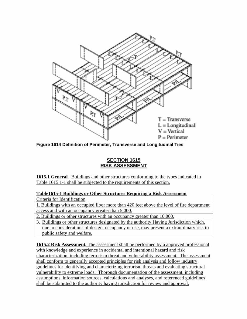
Figure 1614 Definition of Perimeter, Transverse and Longitudinal Ties
SECTION 1615 RISK ASSESSMENT
1615.1 General. Buildings and other structures conforming to the types indicated in Table 1615.1-1 shall be subjected to the requirements of this section. Table1615-1 Buildings or Other Structures Requiring a Risk Assessment Criteria for Identification 1. Buildings with an occupied floor more than 420 feet above the level of fire department access and with an occupancy greater than 5,000. 2. Buildings or other structures with an occupancy greater than 10,000. 3. Buildings or other structures designated by the authority Having Jurisdiction which,
due to considerations of design, occupancy or use, may present a extraordinary risk to public safety and welfare.
1615.2 Risk Assessment. The assessment shall be performed by a approved professional with knowledge and experience in accidental and intentional hazard and risk characterization, including terrorism threat and vulnerability assessment. The assessment shall conform to generally accepted principles for risk analysis and follow industry guidelines for identifying and characterizing terrorism threats and evaluating structural vulnerability to extreme loads. Thorough documentation of the assessment, including assumptions, information sources, calculations and analyses, and referenced guidelines shall be submitted to the authority having jurisdiction for review and approval.
1615.3 Peer Review. When required by the authority having jurisdiction, an independent review of the risk assessment shall be performed by one or more approved professionals. The reviewer(s) shall have knowledge and experience in accidental and intentional hazard and risk characterization, including terrorism threat and vulnerability assessment. The review shall include the assumptions used, the methods of analysis employed, and the findings. Upon completion of the review, the reviewer(s) shall submit a report to the authority having jurisdiction, indicating the scope of review performed and the findings of that review. 1615.4 Mitigation. Risks identified in the risk assessment shall be mitigated in a manner acceptable to the authority having jurisdiction.
Attachment 2
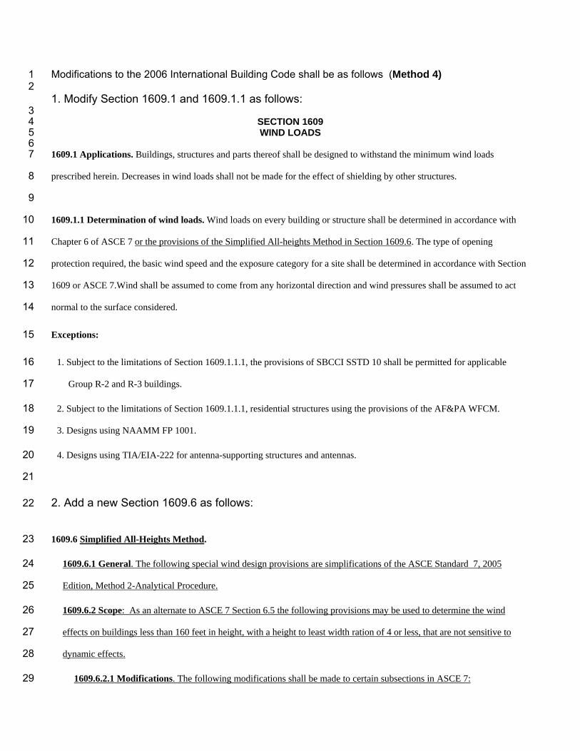
Modifications to the 2006 International Building Code shall be as follows (Method 4) 1 2 1. Modify Section 1609.1 and 1609.1.1 as follows:
3 SECTION 1609 4 WIND LOADS 5
6 1609.1 Applications. Buildings, structures and parts thereof shall be designed to withstand the minimum wind loads 7
prescribed herein. Decreases in wind loads shall not be made for the effect of shielding by other structures. 8
9
1609.1.1 Determination of wind loads. Wind loads on every building or structure shall be determined in accordance with 10
Chapter 6 of ASCE 7 or the provisions of the Simplified All-heights Method in Section 1609.6. The type of opening 11
protection required, the basic wind speed and the exposure category for a site shall be determined in accordance with Section 12
1609 or ASCE 7.Wind shall be assumed to come from any horizontal direction and wind pressures shall be assumed to act 13
normal to the surface considered. 14
Exceptions: 15
1. Subject to the limitations of Section 1609.1.1.1, the provisions of SBCCI SSTD 10 shall be permitted for applicable 16
Group R-2 and R-3 buildings. 17
2. Subject to the limitations of Section 1609.1.1.1, residential structures using the provisions of the AF&PA WFCM. 18
3. Designs using NAAMM FP 1001. 19
4. Designs using TIA/EIA-222 for antenna-supporting structures and antennas. 20
21
2. Add a new Section 1609.6 as follows: 22
1609.6 Simplified All-Heights Method. 23
1609.6.1 General. The following special wind design provisions are simplifications of the ASCE Standard 7, 2005 24
Edition, Method 2-Analytical Procedure. 25
1609.6.2 Scope: As an alternate to ASCE 7 Section 6.5 the following provisions may be used to determine the wind 26
effects on buildings less than 160 feet in height, with a height to least width ration of 4 or less, that are not sensitive to 27
dynamic effects. 28
1609.6.2.1 Modifications. The following modifications shall be made to certain subsections in ASCE 7: 29

Section 1609.6.3 Symbols and Notations are specific to this section in conjunction with the Symbols and 30
Notations in ASCE 7 Section.6.3. 31
1609.6.3 Symbols and Notations 32
1609.6.3.1. Coefficients and variables used in the Simplified All-Heights Method equations are as follows: 33
Cnet = A net-pressure coefficient (See Table 1609.6.4.2(3)), based on the following formula 34
Kd [(G) (Cp) – (GCpi)] 35
G = Gust effect factor equal to 0.85 for rigid buildings per ASCE 7 Section 6.5.8.1. 36
Kd = Wind directionality factor equal to 0.85 for buildings per ASCE 7 Table 6-4. 37
Pnet = Design wind pressure to be used in determination of wind loads on buildings and structures or their 38
components and cladding, in lb/ft2 (N/m2). 39
qs = Wind velocity pressure in lb/ft2 (N/m2). (Per Table 1609.6(1)) 40
1609.6.4 Design Wind Pressures 41
1609.6.4.1 Design Equations. When using the Simplified All-Heights Method, the Main-Wind-Force-Resisting System, 42
(MWFRS) and Components and Cladding of every structure shall be designed to resist the effects of wind pressures on 43
the building envelope in accordance with Equation (6-29). 44
Pnet = qs Kz Cnet [I Kzt] (6-29) 45
Design wind forces for the MWFRS shall not be less than 10 lb/ft2 multiplied by the area of the structure projected on a 46
plane normal to the assumed wind direction. See ASCE Section 6.1.4 for criteria. Design net wind pressure for 47
components and cladding shall not be less than 10 lb/ft2 acting in either direction normal to the surface. 48
1609.6.4.2 Design Procedure. 49
1609.6.4.2.1 General. The MWFRS and the components and cladding of every structure shall be designed for the 50
pressures calculated using Equation (6-29). 51
1609.6.4.2.1.1 Main Wind-Force-Resisting Systems. The MWFRS shall be investigated for the torsional effects 52
identified in ASCE 7 Figure 6-9. 53
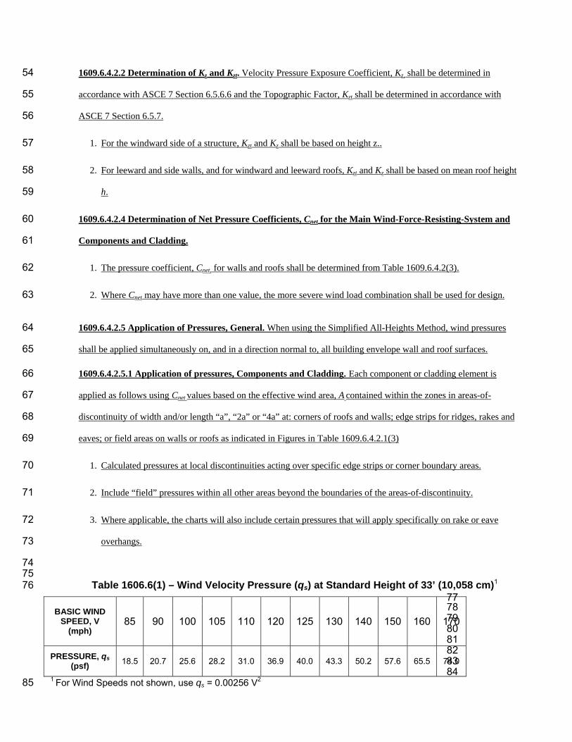
1609.6.4.2.2 Determination of Kz and Kzt. Velocity Pressure Exposure Coefficient, Kz, shall be determined in 54
accordance with ASCE 7 Section 6.5.6.6 and the Topographic Factor, Kzt shall be determined in accordance with 55
ASCE 7 Section 6.5.7. 56
1. For the windward side of a structure, Kzt and Kz shall be based on height z.. 57
2. For leeward and side walls, and for windward and leeward roofs, Kzt and Kz shall be based on mean roof height 58
h. 59
1609.6.4.2.4 Determination of Net Pressure Coefficients, Cnet for the Main Wind-Force-Resisting-System and 60
Components and Cladding. 61
1. The pressure coefficient, Cnet, for walls and roofs shall be determined from Table 1609.6.4.2(3). 62
2. Where Cnet may have more than one value, the more severe wind load combination shall be used for design. 63
1609.6.4.2.5 Application of Pressures, General. When using the Simplified All-Heights Method, wind pressures 64
shall be applied simultaneously on, and in a direction normal to, all building envelope wall and roof surfaces. 65
1609.6.4.2.5.1 Application of pressures, Components and Cladding. Each component or cladding element is 66
applied as follows using Cnet values based on the effective wind area, A contained within the zones in areas-of-67
discontinuity of width and/or length “a”, “2a” or “4a” at: corners of roofs and walls; edge strips for ridges, rakes and 68
eaves; or field areas on walls or roofs as indicated in Figures in Table 1609.6.4.2.1(3) 69
1. Calculated pressures at local discontinuities acting over specific edge strips or corner boundary areas. 70
2. Include “field” pressures within all other areas beyond the boundaries of the areas-of-discontinuity. 71
3. Where applicable, the charts will also include certain pressures that will apply specifically on rake or eave 72
overhangs. 73
74 75
Table 1606.6(1) – Wind Velocity Pressure (qs) at Standard Height of 33’ (10,058 cm)1 76 77 78 79 80 81 82 83 84
1 For Wind Speeds not shown, use qs = 0.00256 V2 85
BASIC WIND SPEED, V
(mph) 85 90 100 105 110 120 125 130 140 150 160 170
PRESSURE, qs (psf) 18.5 20.7 25.6 28.2 31.0 36.9 40.0 43.3 50.2 57.6 65.5 74.0

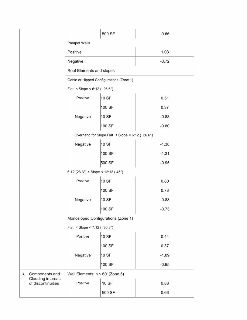
Table 1609.6.1(3) – Net Pressure Coefficients, Cnet 86 87 STRUCTURE OR PART
THEREOF DESCRIPTION Cnet FACTOR
Enclosed WALLS:
Windward Wall 0.73 Leeward Wall -0.21 Side Wall -0.35 Parapet Wall Windward 1.08 Leeward -0.72
ROOFS: Wind perpendicular to ridge Leeward roof or flat roof -0.35 Windward roof slopes:
Slope < 2:12 ( 9.5°) -0.79 Slope = 4:12 ( 18.4°) -0.42 Slope = 5:12 ( 22.6°) -0.28 Slope = 6:12 ( 26.6°) Case 1 -0.16 Case 2 0.20 Slope = 7:12 ( 30.3°) Case 1 -0.06 Case 2 0.30 Slope 9:12 ( 36.9°) to 12:12 ( 45°) Case 1 0.04 Case 2 0.31 Slope > 12:12 ( 45°) 0.37
Wind parallel to ridge and flat roofs -0.79
Chimneys, Tanks and Similar Structures: h/D 1 7 25 Square 0.99 1.07 1.53 Hexagonal or Octagonal 0.81 0.97 1.13 Round 0.65 0.81 0.97
1. Primary Force Resisting Frames and Systems
Wall Elements: h ≤ 60' (Zone 4)
Positive 10 SF 0.88
500 SF 0.66
Negative 10 SF -0.95
500 SF -0.73
Wall Elements: h > 60' (Zone 4)
Positive 20 SF 0.80
500 SF 0.59
2. Components and Cladding not in areas of discontinuity
Negative 20 SF -0.80

500 SF -0.66
Parapet Walls
Positive 1.08
Negative -0.72
Roof Elements and slopes
Gable or Hipped Configurations (Zone 1)
Flat < Slope < 6:12 ( 26.6°)
Positive 10 SF 0.51
100 SF 0.37
Negative 10 SF -0.88
100 SF -0.80
Overhang for Slope Flat < Slope < 6:12 ( 26.6°)
Negative 10 SF -1.38
100 SF -1.31
500 SF -0.95
6:12 (26.6°) < Slope < 12:12 ( 45°)
Positive 10 SF 0.80
100 SF 0.73
Negative 10 SF -0.88
100 SF -0.73
Monosloped Configurations (Zone 1)
Flat < Slope < 7:12 ( 30.3°)
Positive 10 SF 0.44
100 SF 0.37
Negative 10 SF -1.09
100 SF -0.95
Wall Elements: h ≤ 60' (Zone 5)
Positive 10 SF 0.88
3. Components and Cladding in areas of discontinuities
500 SF 0.66

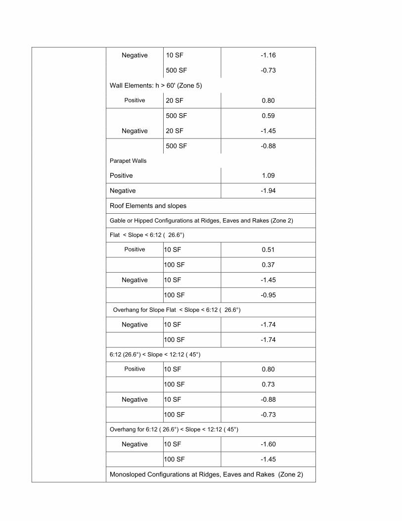
Negative 10 SF -1.16
500 SF -0.73
Wall Elements: h > 60' (Zone 5)
Positive 20 SF 0.80
500 SF 0.59
Negative 20 SF -1.45
500 SF -0.88
Parapet Walls
Positive 1.09
Negative -1.94
Roof Elements and slopes
Gable or Hipped Configurations at Ridges, Eaves and Rakes (Zone 2)
Flat < Slope < 6:12 ( 26.6°)
Positive 10 SF 0.51
100 SF 0.37
Negative 10 SF -1.45
100 SF -0.95
Overhang for Slope Flat < Slope < 6:12 ( 26.6°)
Negative 10 SF -1.74
100 SF -1.74
6:12 (26.6°) < Slope < 12:12 ( 45°)
Positive 10 SF 0.80
100 SF 0.73
Negative 10 SF -0.88
100 SF -0.73
Overhang for 6:12 ( 26.6°) < Slope < 12:12 ( 45°)
Negative 10 SF -1.60
100 SF -1.45
Monosloped Configurations at Ridges, Eaves and Rakes (Zone 2)

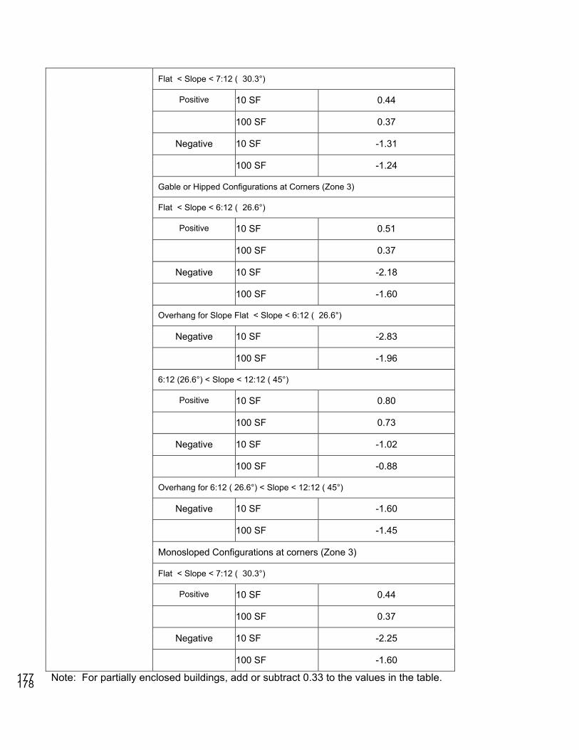
Flat < Slope < 7:12 ( 30.3°)
Positive 10 SF 0.44
100 SF 0.37
Negative 10 SF -1.31
100 SF -1.24
Gable or Hipped Configurations at Corners (Zone 3)
Flat < Slope < 6:12 ( 26.6°)
Positive 10 SF 0.51
100 SF 0.37
Negative 10 SF -2.18
100 SF -1.60
Overhang for Slope Flat < Slope < 6:12 ( 26.6°)
Negative 10 SF -2.83
100 SF -1.96
6:12 (26.6°) < Slope < 12:12 ( 45°)
Positive 10 SF 0.80
100 SF 0.73
Negative 10 SF -1.02
100 SF -0.88
Overhang for 6:12 ( 26.6°) < Slope < 12:12 ( 45°)
Negative 10 SF -1.60
100 SF -1.45
Monosloped Configurations at corners (Zone 3)
Flat < Slope < 7:12 ( 30.3°)
Positive 10 SF 0.44
100 SF 0.37
Negative 10 SF -2.25
100 SF -1.60
Note: For partially enclosed buildings, add or subtract 0.33 to the values in the table. 88 89
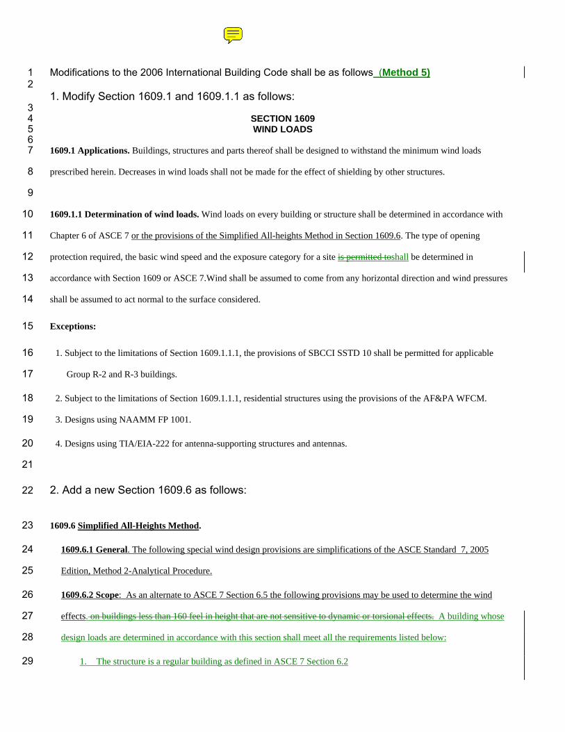
Modifications to the 2006 International Building Code shall be as follows (Method 5) 1 2 1. Modify Section 1609.1 and 1609.1.1 as follows:
3 SECTION 1609 4 WIND LOADS 5
6 1609.1 Applications. Buildings, structures and parts thereof shall be designed to withstand the minimum wind loads 7
prescribed herein. Decreases in wind loads shall not be made for the effect of shielding by other structures. 8
9
1609.1.1 Determination of wind loads. Wind loads on every building or structure shall be determined in accordance with 10
Chapter 6 of ASCE 7 or the provisions of the Simplified All-heights Method in Section 1609.6. The type of opening 11
protection required, the basic wind speed and the exposure category for a site is permitted toshall be determined in 12
accordance with Section 1609 or ASCE 7.Wind shall be assumed to come from any horizontal direction and wind pressures 13
shall be assumed to act normal to the surface considered. 14
Exceptions: 15
1. Subject to the limitations of Section 1609.1.1.1, the provisions of SBCCI SSTD 10 shall be permitted for applicable 16
Group R-2 and R-3 buildings. 17
2. Subject to the limitations of Section 1609.1.1.1, residential structures using the provisions of the AF&PA WFCM. 18
3. Designs using NAAMM FP 1001. 19
4. Designs using TIA/EIA-222 for antenna-supporting structures and antennas. 20
21
2. Add a new Section 1609.6 as follows: 22
1609.6 Simplified All-Heights Method. 23
1609.6.1 General. The following special wind design provisions are simplifications of the ASCE Standard 7, 2005 24
Edition, Method 2-Analytical Procedure. 25
1609.6.2 Scope: As an alternate to ASCE 7 Section 6.5 the following provisions may be used to determine the wind 26
effects. on buildings less than 160 feel in height that are not sensitive to dynamic or torsional effects. A building whose 27
design loads are determined in accordance with this section shall meet all the requirements listed below: 28
1. The structure is a regular building as defined in ASCE 7 Section 6.2 29
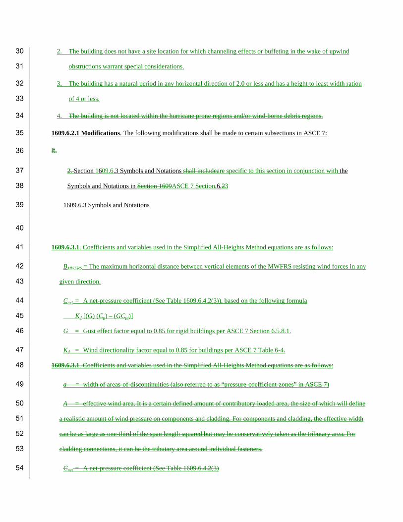
2. The building does not have a site location for which channeling effects or buffeting in the wake of upwind 30
obstructions warrant special considerations. 31
3. The building has a natural period in any horizontal direction of 2.0 or less and has a height to least width ration 32
of 4 or less. 33
4. The building is not located within the hurricane prone regions and/or wind-borne debris regions. 34
1609.6.2.1 Modifications. The following modifications shall be made to certain subsections in ASCE 7: 35
lt. 36
2. Section 1609.6.3 Symbols and Notations shall includeare specific to this section in conjunction with the 37
Symbols and Notations in Section 1609ASCE 7 Section.6.23 38
1609.6.3 Symbols and Notations 39
40
1609.6.3.1. Coefficients and variables used in the Simplified All-Heights Method equations are as follows: 41
BMWFRS = The maximum horizontal distance between vertical elements of the MWFRS resisting wind forces in any 42
given direction. 43
Cnet = A net-pressure coefficient (See Table 1609.6.4.2(3)), based on the following formula 44
Kd [(G) (Cp) – (GCpi)] 45
G = Gust effect factor equal to 0.85 for rigid buildings per ASCE 7 Section 6.5.8.1. 46
Kd = Wind directionality factor equal to 0.85 for buildings per ASCE 7 Table 6-4. 47
1609.6.3.1. Coefficients and variables used in the Simplified All-Heights Method equations are as follows: 48
a = width of areas-of-discontinuities (also referred to as “pressure-coefficient-zones” in ASCE 7) 49
A = effective wind area. It is a certain defined amount of contributory loaded area, the size of which will define 50
a realistic amount of wind pressure on components and cladding. For components and cladding, the effective width 51
can be as large as one-third of the span length squared but may be conservatively taken as the tributary area. For 52
cladding connections, it can be the tributary area around individual fasteners. 53
Cnet = A net-pressure coefficient (See Table 1609.6.4.2(3) 54
= Kd [(G) (Cp) – (GCpi)] 55
= 0.85 [(0.85) (Cp) – (GCpi)] 56
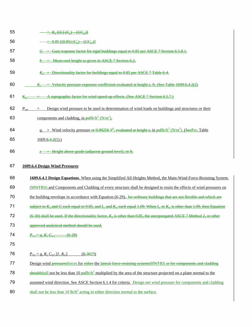
G = Gust response factor for rigid buildings equal to 0.85 per ASCE 7 Section 6.5.8.1. 57
h = Mean roof height as given in ASCE 7 Section 6.2. 58
Kd = Directionality factor for buildings equal to 0.85 per ASCE 7 Table 6-4. 59
Kz = Velocity pressure exposure coefficient evaluated at height z, ft. (See Table 1609.6.4.2(2) 60
Kzt = A topographic factor for wind speed-up effects. (See ASCE 7 Section 6.5.7.) 61
Pnet = Design wind pressure to be used in determination of wind loads on buildings and structures or their 62
components and cladding, in psflb/ft2 (N/m2). 63
qs = Wind velocity pressure or 0.00256 V2, evaluated at height z, in psflb/ft2 (N/m2). (SeePer, Table 64
1609.6.4.2(1).) 65
z = Height above grade (adjacent ground level), in ft. 66
1609.6.4 Design Wind Pressures 67
1609.6.4.1 Design Equations. When using the Simplified All-Heights Method, the Main-Wind-Force-Resisting System, 68
(MWFRS) and Components and Cladding of every structure shall be designed to resist the effects of wind pressures on 69
the building envelope in accordance with Equation (6-29),. for ordinary buildings that are not flexible and which are 70
subject to Kd and G each equal to 0.85, and Iw and Kzt each equal 1.00. When Iw or Kzt is other than 1.00, then Equation 71
(6-30) shall be used. If the directionality factor, Kd is other than 0.85, the unexpurgated ASCE 7 Method 2, or other 72
approved analytical method should be used. 73
Pnet = qs Kz Cnet (6-29) 74
75
Pnet = qs Kz Cnet [Iw Kzt] (6-3029) 76
Design wind pressuresforces for either the lateral-force-resisting systemsMWFRS or for components and cladding 77
shouldshall not be less than 10 psflb/ft2 multiplied by the area of the structure projected on a plane normal to the 78
assumed wind direction. See ASCE Section 6.1.4 for criteria. Design net wind pressure for components and cladding 79
shall not be less than 10 lb/ft2 acting in either direction normal to the surface. 80
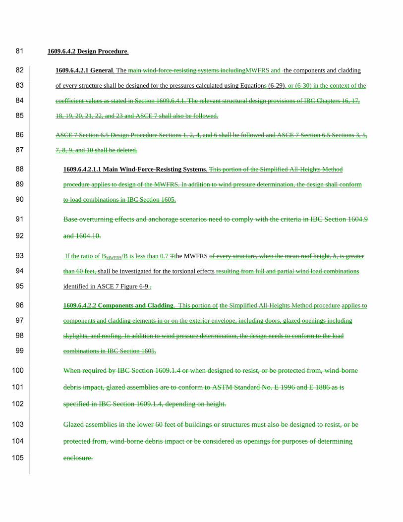
1609.6.4.2 Design Procedure. 81
1609.6.4.2.1 General. The main wind-force-resisting systems includingMWFRS and the components and cladding 82
of every structure shall be designed for the pressures calculated using Equations (6-29). or (6-30) in the context of the 83
coefficient values as stated in Section 1609.6.4.1. The relevant structural design provisions of IBC Chapters 16, 17, 84
18, 19, 20, 21, 22, and 23 and ASCE 7 shall also be followed. 85
ASCE 7 Section 6.5 Design Procedure Sections 1, 2, 4, and 6 shall be followed and ASCE 7 Section 6.5 Sections 3, 5, 86
7, 8, 9, and 10 shall be deleted. 87
1609.6.4.2.1.1 Main Wind-Force-Resisting Systems. This portion of the Simplified All-Heights Method 88
procedure applies to design of the MWFRS. In addition to wind pressure determination, the design shall conform 89
to load combinations in IBC Section 1605. 90
Base overturning effects and anchorage scenarios need to comply with the criteria in IBC Section 1604.9 91
and 1604.10. 92
If the ratio of BMWFRS/B is less than 0.7 Tthe MWFRS of every structure, when the mean roof height, h, is greater 93
than 60 feet, shall be investigated for the torsional effects resulting from full and partial wind load combinations 94
identified in ASCE 7 Figure 6-9.. 95
1609.6.4.2.2 Components and Cladding. This portion of the Simplified All-Heights Method procedure applies to 96
components and cladding elements in or on the exterior envelope, including doors, glazed openings including 97
skylights, and roofing. In addition to wind pressure determination, the design needs to conform to the load 98
combinations in IBC Section 1605. 99
When required by IBC Section 1609.1.4 or when designed to resist, or be protected from, wind-borne 100
debris impact, glazed assemblies are to conform to ASTM Standard No. E 1996 and E 1886 as is 101
specified in IBC Section 1609.1.4, depending on height. 102
Glazed assemblies in the lower 60 feet of buildings or structures must also be designed to resist, or be 103
protected from, wind-borne debris impact or be considered as openings for purposes of determining 104
enclosure. 105
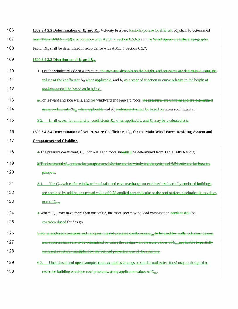
1609.6.4.2.2 Determination of Kz and Kzt. Velocity Pressure FactorExposure Coefficient, Kz, shall be determined 106
from Table 1609.6.4.2(2)in accordance with ASCE 7 Section 6.5.6.6 and the Wind Speed-Up EffectTopographic 107
Factor, Kzt shall be determined in accordance with ASCE 7 Section 6.5.7. 108
1609.6.4.2.3 Distribution of Kz and Kzt. 109
1. For the windward side of a structure, the pressure depends on the height, and pressures are determined using the 110
values of the coefficient Kzt when applicable, and Kz as a stepped function or curve relative to the height of 111
applicationshall be based on height z.. 112
2.For leeward and side walls, and for windward and leeward roofs, the pressures are uniform and are determined 113
using coefficients Kztzt when applicable and Kz evaluated at ashall be based on mean roof height h. 114
3.2. In all cases, for simplicity, coefficients Kzt when applicable, and Kz may be evaluated at h. 115
1609.6.4.2.4 Determination of Net Pressure Coefficients, Cnet for the Main Wind-Force-Resisting-System and 116
Components and Cladding. 117
1.The pressure coefficient, Cnet, for walls and roofs shouldall be determined from Table 1609.6.4.2(3). 118
2.The horizontal Cnet values for parapets are: 1.53 inward for windward parapets, and 0.94 outward for leeward 119
parapets. 120
3.1. The Cnet values for windward roof rake and eave overhangs on enclosed and partially enclosed buildings 121
are obtained by adding an upward value of 0.58 applied perpendicular to the roof surface algebraically to values 122
to roof Cnet. 123
1.Where Cnet may have more than one value, the more severe wind load combination needs toshall be 124
consideredused for design. 125
5.For unenclosed structures and canopies, the net-pressure coefficients Cnet to be used for walls, columns, beams, 126
and appurtenances are to be determined by using the design wall pressure values of Cnet applicable to partially 127
enclosed structures multiplied by the vertical projected area of the structure. 128
6.2. Unenclosed and open canopies (but not roof overhangs or similar roof extensions) may be designed to 129
resist the building envelope roof pressures, using applicable values of Cnet. 130
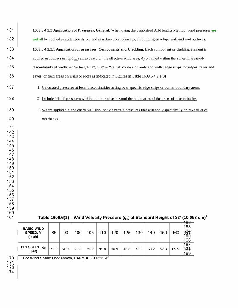
1609.6.4.2.5 Application of Pressures, General. When using the Simplified All-Heights Method, wind pressures are 131
toshall be applied simultaneously on, and in a direction normal to, all building envelope wall and roof surfaces. 132
1609.6.4.2.5.1 Application of pressures, Components and Cladding. Each component or cladding element is 133
applied as follows using Cnet values based on the effective wind area, A contained within the zones in areas-of-134
discontinuity of width and/or length “a”, “2a” or “4a” at: corners of roofs and walls; edge strips for ridges, rakes and 135
eaves; or field areas on walls or roofs as indicated in Figures in Table 1609.6.4.2.1(3) 136
1. Calculated pressures at local discontinuities acting over specific edge strips or corner boundary areas. 137
2. Include “field” pressures within all other areas beyond the boundaries of the areas-of-discontinuity. 138
3. Where applicable, the charts will also include certain pressures that will apply specifically on rake or eave 139
overhangs. 140
141 142 143 144 145 146 147 148 149 150 151 152 153 154 155 156 157 158 159 160
Table 1606.6(1) – Wind Velocity Pressure (qs) at Standard Height of 33’ (10,058 cm)1 161 162 163 164 165 166 167 168 169
1 For Wind Speeds not shown, use qs = 0.00256 V2 170 171
172 173
174
BASIC WIND SPEED, V
(mph) 85 90 100 105 110 120 125 130 140 150 160 170
PRESSURE, qs (psf) 18.5 20.7 25.6 28.2 31.0 36.9 40.0 43.3 50.2 57.6 65.5 74.0

Table 1609.6.1(3) – Net Pressure Coefficients, Cnet 175 176 STRUCTURE OR PART
THEREOF DESCRIPTION Cnet FACTOR
Enclosed WALLS:
Windward Wall 0.73 Leeward Wall -0.21 Side Wall -0.35 Parapet Wall Windward 1.08 Leeward -0.72
ROOFS: Wind perpendicular to ridge Leeward roof or flat roof -0.35 Windward roof slopes:
Slope < 2:12 ( 9.5°) -0.79 Slope = 4:12 ( 18.4°) -0.42 Slope = 5:12 ( 22.6°) -0.28 Slope = 6:12 ( 26.6°) Case 1 -0.16 Case 2 0.20 Slope = 7:12 ( 30.3°) Case 1 -0.06 Case 2 0.30 Slope 9:12 ( 36.9°) to 12:12 ( 45°) Case 1 0.04 Case 2 0.31 Slope > 12:12 ( 45°) 0.37
Wind parallel to ridge and flat roofs -0.79
Chimneys, Tanks and Similar Structures: h/D 1 7 25 Square 0.99 1.07 1.53 Hexagonal or Octagonal 0.81 0.97 1.13 Round 0.65 0.81 0.97
1. Primary Force Resisting Frames and Systems
Wall Elements: h ≤ 60' (Zone 4)
Positive 10 SF 0.88
500 SF 0.66
Negative 10 SF -0.95
500 SF -0.73
Wall Elements: h > 60' (Zone 4)
Positive 20 SF 0.80
500 SF 0.59
2. Components and Cladding not in areas of discontinuity
Negative 20 SF -0.80
500 SF -0.66
Parapet Walls
Positive 1.08
Negative -0.72
Roof Elements and slopes
Gable or Hipped Configurations (Zone 1)
Flat < Slope < 6:12 ( 26.6°)
Positive 10 SF 0.51
100 SF 0.37
Negative 10 SF -0.88
100 SF -0.80
Overhang for Slope Flat < Slope < 6:12 ( 26.6°)
Negative 10 SF -1.38
100 SF -1.31
500 SF -0.95
6:12 (26.6°) < Slope < 12:12 ( 45°)
Positive 10 SF 0.80
100 SF 0.73
Negative 10 SF -0.88
100 SF -0.73
Monosloped Configurations (Zone 1)
Flat < Slope < 7:12 ( 30.3°)
Positive 10 SF 0.44
100 SF 0.37
Negative 10 SF -1.09
100 SF -0.95
Wall Elements: h ≤ 60' (Zone 5)
Positive 10 SF 0.88
3. Components and Cladding in areas of discontinuities
500 SF 0.66
Negative 10 SF -1.16
500 SF -0.73
Wall Elements: h > 60' (Zone 5)
Positive 20 SF 0.80
500 SF 0.59
Negative 20 SF -1.45
500 SF -0.88
Parapet Walls
Positive 1.09
Negative -1.94
Roof Elements and slopes
Gable or Hipped Configurations at Ridges, Eaves and Rakes (Zone 2)
Flat < Slope < 6:12 ( 26.6°)
Positive 10 SF 0.51
100 SF 0.37
Negative 10 SF -1.45
100 SF -0.95
Overhang for Slope Flat < Slope < 6:12 ( 26.6°)
Negative 10 SF -1.74
100 SF -1.74
6:12 (26.6°) < Slope < 12:12 ( 45°)
Positive 10 SF 0.80
100 SF 0.73
Negative 10 SF -0.88
100 SF -0.73
Overhang for 6:12 ( 26.6°) < Slope < 12:12 ( 45°)
Negative 10 SF -1.60
100 SF -1.45
Monosloped Configurations at Ridges, Eaves and Rakes (Zone 2)
Flat < Slope < 7:12 ( 30.3°)
Positive 10 SF 0.44
100 SF 0.37
Negative 10 SF -1.31
100 SF -1.24
Gable or Hipped Configurations at Corners (Zone 3)
Flat < Slope < 6:12 ( 26.6°)
Positive 10 SF 0.51
100 SF 0.37
Negative 10 SF -2.18
100 SF -1.60
Overhang for Slope Flat < Slope < 6:12 ( 26.6°)
Negative 10 SF -2.83
100 SF -1.96
6:12 (26.6°) < Slope < 12:12 ( 45°)
Positive 10 SF 0.80
100 SF 0.73
Negative 10 SF -1.02
100 SF -0.88
Overhang for 6:12 ( 26.6°) < Slope < 12:12 ( 45°)
Negative 10 SF -1.60
100 SF -1.45
Monosloped Configurations at corners (Zone 3)
Flat < Slope < 7:12 ( 30.3°)
Positive 10 SF 0.44
100 SF 0.37
Negative 10 SF -2.25
100 SF -1.60
Note: For partially enclosed buildings, add or subtract 0.33 to the values in the table. 177 178
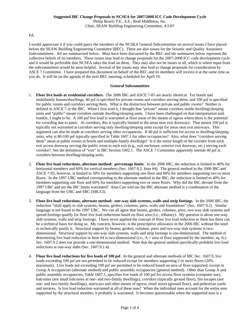
Suggested IBC Change Proposals to NCSEA for 2007/2008 ICC Code Development Cycle Philip Brazil, P.E., S.E., Reid Middleton, Inc.
Chair, SEAW Building Engineering Committee, 4/2/07
Page 1 of 4
Ed, I would appreciate it if you could query the members of the NCSEA General Subcommittee on several issues I have placed before the SEAW Building Engineering Committee (BEC). There are also issues for the Seismic and Quality Assurance Subcommittees. All are summarized below. Most have been discussed by the BEC and the summaries below represent the collective beliefs of its members. These issues may lead to change proposals for the 2007-2008 ICC code development cycle and it would be preferable that NCSEA takes the lead on them. They may also not be issues at all, which is where input from the subcommittees would be most helpful. Several of the issues may also lead to change proposals for consideration by ASCE 7 Committee. I have prepared this document on behalf of the BEC and its members will receive it at the same time as you do. It will be on the agenda of the next BEC meeting, scheduled for April 19.
General Subcommittee 1. Floor live loads at residential corridors. The 2006 IBC and ASCE 7-05 are nearly identical. For hotels and
multifamily houses/dwellings, 40 psf is specified for private rooms and corridors serving them, and 100 psf is specified for public rooms and corridors serving them. What is the distinction between private and public rooms? Neither is defined in ASCE 7 or the IBC. When I first read it, I thought that “private” meant corridors inside dwelling/sleeping units and “public” meant corridors outside dwelling/sleeping units. I have been challenged on that interpretation and, frankly, I ought to be. A 100 psf live load is warranted at floor areas of the means of egress where there is the potential for crowding due to panic. At corridors, this is typically limited to the areas near exit doorways. That means 100 psf is typically not warranted at corridors serving only dwelling/sleeping units except for areas near exit stairways. This argument can also be made at corridors serving other occupancies. If 40 psf is sufficient for access to dwelling/sleeping units, why is 80-100 psf typically specified in Table 1607.1 for other occupancies? Also, what does “corridors serving them” mean at public rooms in hotels and multiple-family dwellings? Is it the entire length of the corridor from each exit access doorway serving the public room to each exit (e.g., exit enclosure, exterior exit doorway, etc.) serving each corridor? See the definition of “exit” in IBC Section 1002.1. The ASCE 7 Committee apparently intends 40 psf at corridors between dwelling/sleeping units.
2. Floor live load reductions, alternate method: percentage limits. In the 2006 IBC, the reduction is limited to 40% for
horizontal members and 60% for vertical members (Sec. 1607.9.2, Item #4). The general method in the 2006 IBC and ASCE 7-05, however, is limited to 50% for members supporting one floor and 60% for members supporting two or more floors. In the 1997 UBC method corresponding to the alternate method in the IBC, the reduction is limited to 40% for members supporting one floor and 60% for members supporting two or more floors. Why did the IBC deviate from the 1997 UBC and are the IBC limits warranted? Alan Carr told me the IBC alternate method is a combination of the language from the UBC and SBC (SBCCI).
3. Floor live load reductions, alternate method: one-way slab systems, walls and strip footings. In the 2006 IBC, the
reduction “shall apply to slab systems, beams, girders, columns, piers, walls and foundations” (Sec. 1607.9.2). Similar language is not found in the 1997 UBC. We can all agree that beams, girders, columns, piers, two-way slab systems and spread footings qualify for floor live load reductions based on floor area (i.e., tributary). My question is about one-way slab systems, walls and strip footings. I have never applied the concept of floor live load reduction to them but there can be a technical basis for doing so. My concern, however, is the prescriptive allowance in the 2006 IBC without the need to technically justify it. Structural support by beams, girders, columns, piers and two-way slab systems is two-dimensional. Structural support by one-way slab systems, walls and strip footings is one-dimensional. The method of determining live load reduction in Item #4 is two-dimensional (i.e., A = area of floor supported by the member, sq. ft.). Sec. 1607.9.2 does not provide a one-dimensional method. Note that the general method specifically prohibits live load reductions at one-way slabs (Sec. 1607.9.1.4).
4. Floor live load reductions for live loads of 100 psf. In the general and alternate methods of IBC Sec. 1607.9, live
loads exceeding 100 psf are not permitted to be reduced except for members supporting 2 or more floors (20% maximum). Live loads not exceeding 100 psf are permitted to be reduced based on area of floor supported, except in Group A occupancies (alternate method) and public assembly occupancies (general method). Other than Group A and public assembly occupancies, Table 1607.1, specifies live loads of 100 psf for access floor systems (computer use), balconies (not small balconies at one- and two-family dwellings), corridors (typically ground floor), fire escapes (not one- and two-family dwellings), stairways and other means of egress, retail stores (ground floor), and pedestrian yards and terraces. Is live load reduction warranted at all of these uses? When the individual uses account for the entire area supported by the structural member, it probably is warranted. It becomes questionable when the supported area is a
Suggested IBC Change Proposals to NCSEA for 2007/2008 ICC Code Development Cycle Philip Brazil, P.E., S.E., Reid Middleton, Inc.
Chair, SEAW Building Engineering Committee, 4/2/07
Page 2 of 4
combination of two uses, which is common at exit stairways, exit passageways and corridors. Reductions in live load at the means of egress should not be permitted.
5. Floor live load reductions, general vs. alternate methods: delete alternate. The presence of two methods for
reducing floor live loads in the 2006 IBC is not warranted. One of the methods should be deleted and it should be the alternate method so that the IBC will be aligned with ASCE 7. John Tawresey should be consulted.
6. Floor live load reductions, general vs. alternate methods: detailed technical issues.
a. What are “public assembly occupancies” in Sec. 1607.9.1.3 (general)? They are not defined. Reference to Group A occupancies in Sec. 1607.9.2, Item #1 (alternate) is preferred.
b. A reduction in floor live load is not permitted in Group A occupancies in the alternate method (Sec. 1607.9.2, Item
#1). Assembly uses, however, could occur in other than Group A occupancies but the occupant load is typically limited to 50 (Sec. 303.1, Exc. 1). Is this sufficient? I believe it is.
c. Why is the rational approach in Exc. 2 to Sec. 1607.9.1 (general) not specified for the alternate method?
d. Why is the permitted reduction in live loads, not otherwise permitted to be reduced, for support of two or more
floors limited to the reduction based on supported area when using the general method (Sec. 1607.9.1.1, Exc. 1, and Sec. 1607.9.1.2) but not when using the alternate method?
e. Why does the general method contain limitations on reductions of roof live loads (Sec. 1607.9.1.4) when Sec.
1607.9 prohibits reductions? This is a conflict that should be eliminated. 7. Roof live load reductions. In the 2006 IBC, Sec. 1607.9 excludes the methods of determining reductions for floor live
loads from also being applied to roof live loads. Sec. 1607.9.1.2 (general) prohibits reductions in roof live loads of 100 psf or less except as specified in Sec. 1607.11.2. Sec. 1607.9.2 (alternate) is silent on reductions in roof live loads. Table 1607.1, Item #30, specifies live loads of 100 psf at roofs used for roof gardens or assembly purposes and 60 psf at roofs used for promenade purposes. Sec. 1607.11.2.2 requires roofs used for promenade purposes, roof gardens, assembly purposes of other special purposes to be designed for the live loads specified in Table 1607.1 and permits them to be reduced in accordance with Section 1607.9. Sec. 1607.9, however, does not permit such reductions. The provisions should be correlated. Refer to CCP S116-06/07(AS) for changes to Sec. 1607.11.2.2.
8. Vehicle barrier systems. 2006 IBC Sec. 1607.7.3 contains technical requirements for vehicle barrier systems (e.g.,
force, height of application, etc.). The purpose for Sec. 1607 is to specify structural loading conditions for handrails, guards, grab bars and vehicle barriers, not the required locations. The IBC, however, contains no charging language requiring the installation of vehicle barrier systems. Sec. 406.2.3 on guards in parking garages should be revised by requiring guards to be designed as vehicle barrier systems in accordance with Sec. 1607.7.3. Note that private garages and carports are currently exempt form the requirement for guards (Sec. 406.1). Sec. 1013 on guards should be revised by referencing Sec. 406.2.3 for guards in parking garages. “Vehicle barriers” should be changed to “vehicle barrier systems” in Sec. 1607.7 for consistency with Sec. 1607.7.3. Note that Sec. 1013.1 on guards references Sec. 1607.7. Sec. 1012 on handrails does not have a similar reference but it is not critical for it to do so. Required locations for grab bars are found in ICC A117.1. This may not be appropriate for NCSEA to pursue since the issue concerns public policy rather than structural design. Note that Sec. 1602.1 defines “vehicle barrier system.”
9. Roof planters as dead load or live load. 2006 IBC Sec. 1607.11.2.3 specifies the weight of landscaping materials at
landscaped roofs as dead load computed on the basis of saturation of the soil. A minimum roof live load of 20 psf at the landscaped area is also required. This live load is not specified in Table 1607.1, Item #30, with the other roof live loads. Similar language identifying the weight of landscaping materials as dead load is not found in Sec. 1608 on snow load. There has been confusion whether such materials are considered dead load or live load when roof planters are located on occupied roof decks in regions where snow load governs the design of roofs. Sec. 1607.11.2.3 should be relocated to Sec. 1606 on dead load except for the minimum live load requirement, which should be added to Table 1607.1, Item #30. Note that, when snow load governs, the design snow load is determined by the provisions in Ch. 7 of ASCE 7 provided the load is not less than that determined by Sec. 1607. Consider adding “weight of landscaping materials” to definition of “dead load” in Sec. 1602.1.

Suggested IBC Change Proposals to NCSEA for 2007/2008 ICC Code Development Cycle Philip Brazil, P.E., S.E., Reid Middleton, Inc.
Chair, SEAW Building Engineering Committee, 4/2/07
Page 3 of 4
10. Roof live loads when used as roof gardens and for promenade, assembly or other special purposes. 2006 IBC Sec. 1607.11.2.2 references Table 1607.1 for required live loads at roofs used as roof gardens and for promenade, assembly or other special purposes. None of these terms are defined. Sec. 1607.11.2.2 permits reductions in accordance with Sec. 1607.9 but Sec. 1607.9 typically does not permit reductions at assembly areas, which appears to conflict with Sec. 1607.11.2.2. The live load in Table 1607.1 is 60 psf for promenades and 100 psf for roof gardens and assembly areas. The distinction between a promenade and an assembly area is not clear. Whether the requirement for a live load of 100 psf is required at the landscaped areas of roof gardens (see Item #9 above) is also not clear. Several change proposals are warranted. At least one proposal has apparently been submitted to the ASCE 7 committee.
11. Load combinations at occupied roofs. The combination of snow load and floor live load at occupied roofs for parking,
promenades, roof gardens, decks and assembly areas is uncertain. 2006 IBC Sec. 1605.1 requires buildings and other structures be designed to resist the load combinations in Sec. 1605.2 (LRFD) or 1605.3 (ASD) and elsewhere in the IBC as applicable. What it does not do is clearly specify when load combinations are required to be applied. Typically, we don’t need further clarity but there are notable exceptions and occupied roofs are one of them. Sec. 1607.11 appears to require designers to consider combinations of wind/earthquake, dead, live and snow loads but improvements would be helpful. The ASCE 7 Committee apparently believes this issue is sufficiently addressed by the applicable LRFD load combinations, which typically combine full floor live load with reduced snow load and full snow load with reduced floor live load. The ASD load combinations, however, typically combine full floor live load with full snow load and this does not address whether the IBC provisions clearly require the combination of snow and floor live loads in all cases.
12. Partitions as dead load or live load. 2006 IBC Sec. 1602.1 defines “dead load,” in part, as consisting of walls and
built-in partitions. Sec. 1607.5 requires provisions be made for partition weight in office buildings and in other buildings where partition locations are subject to change whether or not partitions are shown on the construction documents. “Load-bearing wall” and “nonload-bearing wall” are defined (Sec. 202) but “partition” is not. There is confusion as to whether the partition weight required by Sec. 1607.5 is a live load or a dead load and, if it is a live load, whether it can be included in the floor live floor when applying Sec. 1607.9 for the reduction of live loads. Also, there is no clear distinction between “built-in partitions” and “partition weight.” A suggestion would be to change “partition weight” in Sec. 1607.5 to “partition live load.” Another suggestion would be to add an exception to Section 1607.5 for built-in partitions included in the dead load as defined in Sec. 1602.1.
13. Reductions in partition live loads. Partition weight required by Sec. 1607.5 (see item #10 above) is excluded from
qualifying for reductions along with floor live load only because it is not included in Table 1607.1 (see Sec. 1607.9). There is confusion as to whether this is the intent. Reductions in floor live load based on supported floor area are justified for reasons distinctly different than may be valid for similar reductions in partition weight. Sec. 1607.9 should be revised to specifically exclude partition weight.
14. Retaining walls and nonseismic surcharges. Retaining and foundation walls are typically designed for out-of-plane
loads consisting of a lateral earth pressure and a horizontal surcharge due to vertical loads applied to the ground surface opposite the top of the wall due to sidewalks, driveways, roadways, etc. When applying the load combinations of 2006 IBC Sec. 1605, there is confusion over whether the horizontal surcharge is a lateral earth pressure (H) or a live load (L). The Notations in Sec. 1602.1 should be revised to specify which one the horizontal surcharge is.
15. Hazardous materials and occupancy category. 2006 IBC Table 1604.5 classifies buildings and other structures
containing sufficient quantities of toxic or explosive substances to be dangerous to the public if released as Occupancy Category III, and containing highly toxic materials whose quantities exceed the maximum allowable quantities of Table 307.1(2) as Occupancy Category III. The first classification is vague and enforceable. Questions have been raised over whether the second classification is warranted because highly toxic materials can be located in a building or structure whose release would have minimal impact on its structural integrity (i.e., gas cylinders in a wood rack located on a concrete slab-on-grade). The hazard to buildings and other structures by all hazardous materials, not just toxic and explosive materials, is largely due to the risk posed by conveyances (i.e., suspended piping) releasing the materials in a seismic event. This risk may be better addressed by focusing on the design of the conveyances as nonstructural components. The listings for toxic and explosive materials in IBC Table 1604.5 should be deleted. Note that the component importance factor of 1.5 in Sec. 13.1.3 of ASCE 7-05 applies to all hazardous materials. Refer to IBC Sec. 307.2 for a definition of “hazardous material.”
16. Mean roof height. “Mean roof height” is specified in Exc. 1 to 2006 IBC Sec. 1609.1.2. It also appears at several
locations in Ch. 15. The term is not defined but Sec. 6.2 of ASCE 7-05 does define it. Item #2 of 2006 IBC Sec. 1709.3
Suggested IBC Change Proposals to NCSEA for 2007/2008 ICC Code Development Cycle Philip Brazil, P.E., S.E., Reid Middleton, Inc.
Chair, SEAW Building Engineering Committee, 4/2/07
Page 4 of 4
specifies “building height,” which is defined in Sec. 502.1. The definition in ASCE 7-05 for mean roof height should be added to the IBC or the references to mean roof height should be changed to building height.
17. Parts versus portions. 2006 IBC Sec. 1604.1, 1604.2 and 1609.1 typically specify “buildings, structures and parts
thereof.” “Parts” should be changed to portions” for consistency with other provisions in the IBC (approximately 25 locations).
18. Restrictions, posting and changes in design loads. Consider relocating 2006 IBC Sec. 1603.2-1603.4 on load
restrictions, posting of loads and permits for changed loads to Ch. 1. These issues are typically not part of structural design but are typically part of code enforcement.
19. Shower seats and dressing room bench seats. Shower seats and dressing room bench seats should be added to the
charging language in 2006 IBC Sec. 1607.7 for consistency with Sec. 1607.7.2. Phil Brazil, P.E., S.E., Chair
Attachment 5
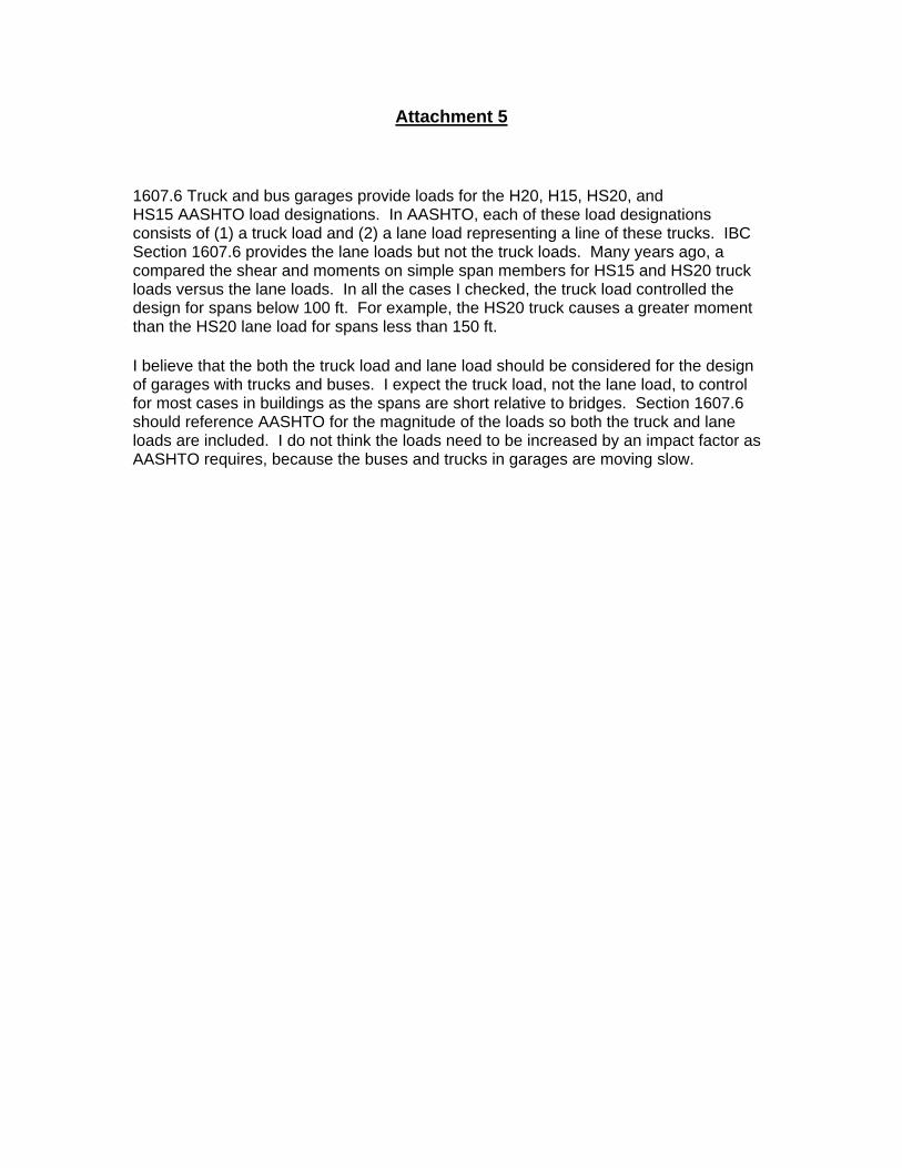
1607.6 Truck and bus garages provide loads for the H20, H15, HS20, and HS15 AASHTO load designations. In AASHTO, each of these load designations consists of (1) a truck load and (2) a lane load representing a line of these trucks. IBC Section 1607.6 provides the lane loads but not the truck loads. Many years ago, a compared the shear and moments on simple span members for HS15 and HS20 truck loads versus the lane loads. In all the cases I checked, the truck load controlled the design for spans below 100 ft. For example, the HS20 truck causes a greater moment than the HS20 lane load for spans less than 150 ft.
I believe that the both the truck load and lane load should be considered for the design of garages with trucks and buses. I expect the truck load, not the lane load, to control for most cases in buildings as the spans are short relative to bridges. Section 1607.6 should reference AASHTO for the magnitude of the loads so both the truck and lane loads are included. I do not think the loads need to be increased by an impact factor as AASHTO requires, because the buses and trucks in garages are moving slow.
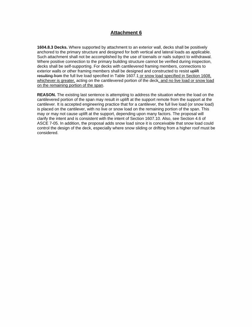
Attachment 6 1604.8.3 Decks. Where supported by attachment to an exterior wall, decks shall be positively anchored to the primary structure and designed for both vertical and lateral loads as applicable. Such attachment shall not be accomplished by the use of toenails or nails subject to withdrawal. Where positive connection to the primary building structure cannot be verified during inspection, decks shall be self-supporting. For decks with cantilevered framing members, connections to exterior walls or other framing members shall be designed and constructed to resist uplift resulting from the full live load specified in Table 1607.1 or snow load specified in Section 1608, whichever is greater, acting on the cantilevered portion of the deck, and no live load or snow load on the remaining portion of the span. REASON. The existing last sentence is attempting to address the situation where the load on the cantilevered portion of the span may result in uplift at the support remote from the support at the cantilever. It is accepted engineering practice that for a cantilever, the full live load (or snow load) is placed on the cantilever, with no live or snow load on the remaining portion of the span. This may or may not cause uplift at the support, depending upon many factors. The proposal will clarify the intent and is consistent with the intent of Section 1607.10. Also, see Section 4.6 of ASCE 7-05. In addition, the proposal adds snow load since it is conceivable that snow load could control the design of the deck, especially where snow sliding or drifting from a higher roof must be considered.
Attachment 7 Part 1: From a member of the NCEES Structural 1 committee
I have questions about foundation design that may be pertinent to test questions.
1. I was taught to design spread footings so that there is no uplift at the heel, i.e, the resultant is within the kern or middle third for soils and middle ½ for rock. I noticed that there was an example that based the design on the max pressure without regard to heel uplift. I could not find anything in the code pertaining to the heel uplift condition requirements. Do you know of anything?
2. It used to be that we would design spread footings to have a factor of safety of 1.5 against overturning, 1.5 against sliding and 1.5 against total uplift. (These are code requirements for retaining walls in ASCE 7-05). With the ASCE 7-98 and since, one of the ASD load combinations is 0.6D+W. If this load case is to be used in checking OT, sliding and uplift the design requirements are changed significantly from before the 0.6 factor. It seems like this already has a FOS in it of 1/0.6 for dead loads. Is it intended that the stability requirement FOS be modified for the new load combinations?
Do you have any information pertaining to these questions or do you know of anyone who may?
Thanks,
Randall P. Bernhardt, P.E., S.E.
Burns & McDonnell Engineering Company, Inc.
1630 Des Peres Road
Saint Louis, Missouri 63131
314-821-9016 Fax 314-821-5406
Mobil 314-660-4367
________________________________________________________________________ Part 2 Bill: You are correct, the 0.6D + 1.0W load combination has a 1.5 factor of safety built into it from the top of the roof to the foundation. This is one of the problems with this load combination. You need the 1.5 FOS to keep the roof on. Once you mobilize enough dead load to do that, you should be allowed to use a different multiplier (like 0.9) until you get to the foundation. Then you need the 1.5 FOS again for overturning and sliding. For light buildings in high seismic areas, this load combination is a killer at the base of the shear walls. That's why we fight so hard to keep the alternate allowable load combinations. In ASCE 7 they dropped the 1.5 FOS on overturning and sliding when they went to the 0.6 D factor. There a good chance we'll get this fixed in the next ASCE 7. At least those conversations are starting. Watch out though. If your lateral load is from something else (soil pressure, water pressure, etc.) and wind load doesn't control, you may need to apply the 1.5 factor separately, outside the load combination. That's why there is the comment on retaining walls. But there isn't a similar global requirement to address any other lateral loads. I liked the old separate 1.5 requirement better, but it didn't keep the roofs on the buildings. Hope this helps happy Holidays Ed William Kussro wrote: Ed and Stephanie: Read below. This may seem like a very basic thing but we have a debate in our design office regarding the 0.6D+1.0W ASD load combination. When using this load combination for foundation proportioning do you still have to maintain the standard FS=1.5 for overturning, sliding, uplift, etc.? It seems that if you do then you're "double counting" the factor of safety (i..e the FS is already built into the load combination itself). Just let me know what you think when you get a minute. Thanks and have a great holiday season. Regards, Bill William B. Kussro, PE, MLSE, CCS Manager, Structural and Civil Engineering LEED Accredited Professional Giffels, Inc. - Southfield, MI
Phone: 248.936.8376 Cell: 810.287.6509 Fax: 248.936.8377 Website: www.giffels.com E-mail: [email protected]
William Kussro, PE, MLSE, CCS, LEED Manager, Structural and Civil Engineering Giffels, Inc.
From: William Kussro Sent: Friday, September 08, 2006 10:15 AM To: Khaled Nahlawi Cc: Brock Nurenberg Subject: RE: Question Regarding Increase in Soil Pressures
Khaled: Yes, what you say makes sense but I'm not sure that it's exactly what the Building Code says. The 2003 IBC Section 1801.2 says "Allowable bearing pressures, allowable stresses and design formulas provided in this chapter shall be used with the allowable stress design load combinations in Section 1605.3". These load combinations include the 0.6D+W and 0.6D+0.7E load combos. It doesn't specifically say that overturning, sliding, etc. should be independently checked using "logical" load combinations such as 0.9D+W or 0.9D+E (i.e. using unreduced dead loads) using a FS=1.5 but I think that is what they mean. I will review this with ICC. Thank you both for your input. Regards, Bill
From: Brock Nurenberg Sent: Friday, September 08, 2006 8:32 AM To: William Kussro Cc: Khaled Nahlawi Subject: RE:Question Regarding Increase in Soil Pressures
Bill, I used the electronic version of the IBC we have on the system to run a search for "overturning" "stability" "1.5" and other similar queries. A statement where all foundations are required to have a 1.5 factor of safety over the revised ASD combos is not in the code. I can recall it was in either the 96 BOCA or 97 UBC which, but apparently not the IBC. The only place it states 1.5 factor of safety is for retaining walls. Some of the special wood provisions with seimic have extra requirements. Based on all this, I think we just need to provide sufficient dead load resisting moment and sliding resistance for 1.0 times the applied forces resulting from the ASD load combos listed. 1604.4 Analysis.
Every structure shall be designed to resist the overturning effects caused by the lateral forces specified in this chapter. See Section 1609 for wind, Section 1610 for lateral soil loads and Sections 1613 through 1623 for earthquake. 1604.8.1 General. Anchorage of the roof to walls and columns, and of walls and columns to foundations, shall be provided to resist the uplift and sliding forces that result from the application of the prescribed loads. 1801.2 Design. Allowable bearing pressures, allowable stresses and design formulas provided in this chapter shall be used with the allowable stress design load combinations specified in Section 1605.3. The quality and design of materials used structurally in excavations, footings and foundations shall conform to the requirements specified in Chapters 16, 19, 21, 22 and 23 of this code. Excavations and fills shall also comply with Chapter 33. 1801.2.1 Foundation design for seismic overturning. Where the foundation is proportioned using the strength design load combinations of Section 1605.2, the seismic overturning moment need not exceed 75 percent of the value computed from Section 9.5.5.6 of ASCE7 for the equivalent lateral force method, or Section 1618 for the modal analysis method.
Brock Nurenberg Structural Engineer Giffels, Inc.
From: Khaled Nahlawi Sent: Friday, September 08, 2006 9:12 AM To: William Kussro Cc: Brock Nurenberg Subject: RE:Question Regarding Increase in Soil Pressures The FS=1.5 is used for dead load only without any reduction factors to the dead load. The code requirement is basically to ensure that resisting moment (due to dead load only) > 1.5 overturning moment (wind or seismic). The later code combination factors have included a reduction factor to the dead load only in combination with wind loading. 0.6xresisting moment (dead load only) > overturning moment (wind or seismic) It's basically the same with minor adjustment to factors of safety. Regards, Khaled
Khaled Nahlawi
Project Structural Engineer Giffels, Inc.
From: William Kussro Sent: Friday, September 08, 2006 8:11 AM To: Brock Nurenberg Cc: Khaled Nahlawi Subject: RE:Question Regarding Increase in Soil Pressures
Brock: OK, doesn't it specifically say in the Code to use the ASD load combos for proportioning foundations and checking stability? If so where does it say that? Anyway, if it does say that then it seems that you are already using 0.6D and then making sure you have a FS=1.5 on top of that. This would be a problem in isolated ground or pile supported foundations subject to overturning due to either wind or seismic loads (as well as other types of foundations). Maybe I'm reading too much into this but this is how I interpret it. Comments? Regards, Bill
William Kussro, PE, MLSE, CCS, LEED Manager, Structural and Civil Engineering Giffels, Inc.
From: Brock Nurenberg Sent: Wednesday, August 30, 2006 8:01 AM To: William Kussro Subject: RE:Question Regarding Increase in Soil Pressures
Bill, It looks like you are correct. Load combinations 7 and 8 were new to the 1998 edition of ASCE 7. They address the situation in which the effects of lateral or uplift forces counteract the effect of gravity loads. This eliminates
an inconsistency in the treatment of counteracting loads in allowable stress design and strength design, and emphasizes the importance of checking stability. The earthquake load effect is multiplied by 0.7 to align allowable stress design for earthquake effects with the definition of E in Section 12.4, which is based on strength principles. 1609.1.3 Anchorage against overturning, uplift and sliding. Structural members and systems and components and cladding in a building or structure shall be anchored to resist wind-induced overturning, uplift and sliding and to provide continuous load paths for these forces to the foundation. Where a portion of the resistance to these forces is provided by dead load, the dead load, including the weight of soils and foundations, shall be taken as the minimum dead load likely to be in place during a design wind event. Where the alternate basic load combinations of Section 1605.3.2 are used, only two-thirds of the minimum dead load likely to be in place during a design wind event shall be used. 1806.1 General. Retaining walls shall be designed to ensure stability against overturning, sliding, excessive foundation pressure and water uplift. Retaining walls shall be designed for a safety factor of 1.5 against lateral sliding and overturning.
Brock Nurenberg Structural Engineer Giffels, Inc.
From: William Kussro Sent: Tuesday, August 29, 2006 5:50 PM To: Brock Nurenberg Subject: RE:Question Regarding Increase in Soil Pressures
Brock: OK, I have another general question. When designing foundations and checking the factor of safety against overturning and sliding failures, by using the 0.6D+W load combination it seems that you're inherently building in a larger factor of safety than earlier versions of the code that had the similar load combo as 0.9D+W, correct? The factor of safety is already kind of "built in" to the 0.6 factor. Any comments? Regards, Bill
William Kussro, PE, MLSE, CCS, LEED Manager, Structural and Civil Engineering Giffels, Inc.
From: Brock Nurenberg Sent: Tuesday, August 29, 2006 3:24 PM To: William Kussro Subject: RE:Question Regarding Increase in Soil Pressures
Bill, It isn't immediately obvious (except the vertical Ev) why the code mentions a one-third allowable stress increase in the earthquake load section instead of the foundation section: 1616.1 Structural design criteria. Allowable stress design is permitted to be used to evaluate sliding, overturning and soil bearing at the soil-structure interface regardless of the approach used in the design of the structure, provided load combinations of Section 1605.3 are utilized. When using allowable stress design for proportioning foundations, the value of 0.2 SDSD in Equations 16-50, 16-51, 16-52 and 16-53 or Equations 9.5.2.7-1, 9.5.2.7-2, 9.5.2.7.1-1 and 9.5.2.7.1-2 of ASCE 7 is permitted to be taken equal to zero. When the load combinations of Section 1605.3.2 are utilized, a one-third increase in soil allowable stresses is permitted for all load combinations that include W or E. 1605.3.2 Alternative basic load combinations These are the old school allowable stress design combos.
Brock Nurenberg Structural Engineer Giffels, Inc. From: William Kussro Sent: Tuesday, August 29, 2006 2:58 PM To: Brock Nurenberg Subject: Question Regarding Increase in Soil Pressures
Brock: General question. Where in the 2003 IBC does it say that the one-third increase in allowable soil pressures is not allowed for foundation design? I know it says this somewhere but I just can't find it right now. Just let me know when you have a chance. Thanks, Bill
William Kussro, PE, MLSE, CCS, LEED Manager, Structural and Civil Engineering Giffels, Inc.
Attachment 8
ICC Standards Proposal e-form Revised: June 2, 2005
CD#: Date Rec’d.: Log
No.: Comment No.:
ICC STANDARDS - PUBLIC COMMENT FORM
PLEASE SEE INSTRUCTIONS (SUBMITTAL RULES OF PROCEDURES). ALL SUBMITTALS MUST BE IN COMPLIANCE WITH THESE PROCEDURES.
CLOSING DATE: All Comments Must Be Received by the Announced Closing Date.
1) Indicate the format in which you would like to receive your Public Comments Report (PCR):
X Paper * CD *Download
(*Note: A paper copy will not be sent to you if you have chosen a CD or to download the PCR from the ICC Web Site.)
2) PLEASE TYPE OR PRINT CLEARLY: FORMS WILL BE RETURNED if they contain unreadable information.
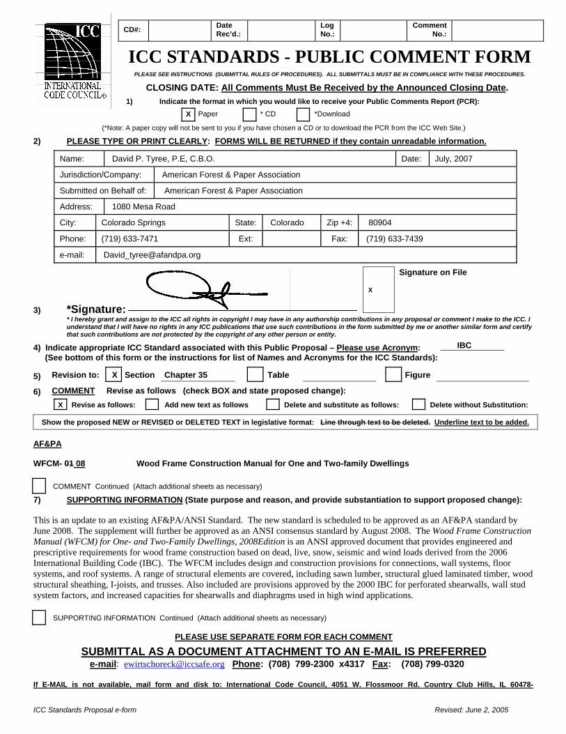
Name: David P. Tyree, P.E, C.B.O. Date: July, 2007
Jurisdiction/Company: American Forest & Paper Association
Submitted on Behalf of: American Forest & Paper Association
Address: 1080 Mesa Road
City: Colorado Springs State: Colorado Zip +4: 80904
Phone: (719) 633-7471 Ext: Fax: (719) 633-7439
e-mail: [email protected]
3) *Signature: * I hereby grant and assign to the ICC all rights in copyright I may have in any authorship contributions in any proposal or comment I make to the ICC. I understand that I will have no rights in any ICC publications that use such contributions in the form submitted by me or another similar form and certify that such contributions are not protected by the copyright of any other person or entity.
4) Indicate appropriate ICC Standard associated with this Public Proposal – Please use Acronym: (See bottom of this form or the instructions for list of Names and Acronyms for the ICC Standards):
5) Revision to: X Section Chapter 35 Table Figure 6) COMMENT Revise as follows (check BOX and state proposed change):
X Revise as follows: Add new text as follows Delete and substitute as follows: Delete without Substitution:
Show the proposed NEW or REVISED or DELETED TEXT in legislative format: Line through text to be deleted. Underline text to be added. AF&PA WFCM- 01 08 Wood Frame Construction Manual for One and Two-family Dwellings COMMENT Continued (Attach additional sheets as necessary)
7) SUPPORTING INFORMATION (State purpose and reason, and provide substantiation to support proposed change): This is an update to an existing AF&PA/ANSI Standard. The new standard is scheduled to be approved as an AF&PA standard by June 2008. The supplement will further be approved as an ANSI consensus standard by August 2008. The Wood Frame Construction Manual (WFCM) for One- and Two-Family Dwellings, 2008Edition is an ANSI approved document that provides engineered and prescriptive requirements for wood frame construction based on dead, live, snow, seismic and wind loads derived from the 2006 International Building Code (IBC). The WFCM includes design and construction provisions for connections, wall systems, floor systems, and roof systems. A range of structural elements are covered, including sawn lumber, structural glued laminated timber, wood structural sheathing, I-joists, and trusses. Also included are provisions approved by the 2000 IBC for perforated shearwalls, wall stud system factors, and increased capacities for shearwalls and diaphragms used in high wind applications.
SUPPORTING INFORMATION Continued (Attach additional sheets as necessary)
PLEASE USE SEPARATE FORM FOR EACH COMMENT
SUBMITTAL AS A DOCUMENT ATTACHMENT TO AN E-MAIL IS PREFERRED e-mail: [email protected] Phone: (708) 799-2300 x4317 Fax: (708) 799-0320
If E-MAIL is not available, mail form and disk to: International Code Council, 4051 W. Flossmoor Rd. Country Club Hills, IL 60478-
X
Signature on File
IBC

ICC Standards Proposal e-form Revised: June 2, 2005
CD#: Date Rec’d.: Log
No.: Comment No.:
ICC STANDARDS - PUBLIC COMMENT FORM
PLEASE SEE INSTRUCTIONS (SUBMITTAL RULES OF PROCEDURES). ALL SUBMITTALS MUST BE IN COMPLIANCE WITH THESE PROCEDURES.
CLOSING DATE: All Comments Must Be Received by the Announced Closing Date.
1) Indicate the format in which you would like to receive your Public Comments Report (PCR):
X Paper * CD *Download
(*Note: A paper copy will not be sent to you if you have chosen a CD or to download the PCR from the ICC Web Site.)
2) PLEASE TYPE OR PRINT CLEARLY: FORMS WILL BE RETURNED if they contain unreadable information.
Name: David P. Tyree, P.E, C.B.O. Date: July, 2007
Jurisdiction/Company: American Forest & Paper Association
Submitted on Behalf of: American Forest & Paper Association
Address: 1080 Mesa Road
City: Colorado Springs State: Colorado Zip +4: 80904
Phone: (719) 633-7471 Ext: Fax: (719) 633-7439
e-mail: [email protected]
3) *Signature: * I hereby grant and assign to the ICC all rights in copyright I may have in any authorship contributions in any proposal or comment I make to the ICC. I understand that I will have no rights in any ICC publications that use such contributions in the form submitted by me or another similar form and certify that such contributions are not protected by the copyright of any other person or entity.
4) Indicate appropriate ICC Standard associated with this Public Proposal – Please use Acronym: (See bottom of this form or the instructions for list of Names and Acronyms for the ICC Standards):
5) Revision to: X Section Chapter 43 Table Figure 6) COMMENT Revise as follows (check BOX and state proposed change):
X Revise as follows: Add new text as follows Delete and substitute as follows: Delete without Substitution:
Show the proposed NEW or REVISED or DELETED TEXT in legislative format: Line through text to be deleted. Underline text to be added. AF&PA WFCM- 2001 08 Wood Frame Construction Manual for One and Two-family Dwellings COMMENT Continued (Attach additional sheets as necessary)
7) SUPPORTING INFORMATION (State purpose and reason, and provide substantiation to support proposed change): This is an update to an existing AF&PA/ANSI Standard. The new standard is scheduled to be approved as an AF&PA standard by June 2008. The supplement will further be approved as an ANSI consensus standard by August 2008. The Wood Frame Construction Manual (WFCM) for One- and Two-Family Dwellings, 2008Edition is an ANSI approved document that provides engineered and prescriptive requirements for wood frame construction based on dead, live, snow, seismic and wind loads derived from the 2006 International Building Code (IBC). The WFCM includes design and construction provisions for connections, wall systems, floor systems, and roof systems. A range of structural elements are covered, including sawn lumber, structural glued laminated timber, wood structural sheathing, I-joists, and trusses. Also included are provisions approved by the 2000 IBC for perforated shearwalls, wall stud system factors, and increased capacities for shearwalls and diaphragms used in high wind applications.
SUPPORTING INFORMATION Continued (Attach additional sheets as necessary)
PLEASE USE SEPARATE FORM FOR EACH COMMENT
SUBMITTAL AS A DOCUMENT ATTACHMENT TO AN E-MAIL IS PREFERRED e-mail: [email protected] Phone: (708) 799-2300 x4317 Fax: (708) 799-0320
If E-MAIL is not available, mail form and disk to: International Code Council, 4051 W. Flossmoor Rd. Country Club Hills, IL 60478-
X
Signature on File
IRC

ICC Standards Proposal e-form Revised: June 2, 2005
CD#: Date Rec’d.: Log
No.: Comment No.:
ICC STANDARDS - PUBLIC COMMENT FORM
PLEASE SEE INSTRUCTIONS (SUBMITTAL RULES OF PROCEDURES). ALL SUBMITTALS MUST BE IN COMPLIANCE WITH THESE PROCEDURES.
CLOSING DATE: All Comments Must Be Received by the Announced Closing Date.
1) Indicate the format in which you would like to receive your Public Comments Report (PCR):
X Paper * CD *Download
(*Note: A paper copy will not be sent to you if you have chosen a CD or to download the PCR from the ICC Web Site.)
2) PLEASE TYPE OR PRINT CLEARLY: FORMS WILL BE RETURNED if they contain unreadable information.
Name: David P. Tyree, P.E, C.B.O. Date: July, 2007
Jurisdiction/Company: American Forest & Paper Association
Submitted on Behalf of: American Forest & Paper Association
Address: 1080 Mesa Road
City: Colorado Springs State: Colorado Zip +4: 80904
Phone: (719) 633-7471 Ext: Fax: (719) 633-7439
e-mail: [email protected]
3) *Signature: * I hereby grant and assign to the ICC all rights in copyright I may have in any authorship contributions in any proposal or comment I make to the ICC. I understand that I will have no rights in any ICC publications that use such contributions in the form submitted by me or another similar form and certify that such contributions are not protected by the copyright of any other person or entity.
4) Indicate appropriate ICC Standard associated with this Public Proposal – Please use Acronym: (See bottom of this form or the instructions for list of Names and Acronyms for the ICC Standards):
5) Revision to: X Section Chapter 35 Table Figure 6) COMMENT Revise as follows (check BOX and state proposed change):
X Revise as follows: Add new text as follows Delete and substitute as follows: Delete without Substitution:
Show the proposed NEW or REVISED or DELETED TEXT in legislative format: Line through text to be deleted. Underline text to be added. AF&PA T.R. No. 7-87 AF&PA PWF-2007 Technical Report – Basic Requirements for Permanent Wood Foundation System Permanent Wood Foundation Design Specification COMMENT Continued (Attach additional sheets as necessary)
7) SUPPORTING INFORMATION (State purpose and reason, and provide substantiation to support proposed change): This is an update to an existing AF&PA technical report which has been revised now to be a standard. The new standard is approved as an AF&PA standard and will further be approved as an ANSI consensus standard by August 2007. AF&PA's new standard for the design of Permanent Wood Foundations (PWF) entitled PWF Design Specification (AF&PA PWF-2007) was developed and balloted through AF&PA's Wood Design Standards Committee (WDSC), an ANSI-approved standards development group. The new PWF Design Specification was written as part of an effort to update design recommendations and procedures in the wood industry's documents design aides, such as Technical Report 7: The Permanent Wood Foundation System (1987) and the The Permanent Wood Foundation System: Design, Fabrication and Installation Manual (1987). Development of the new standard provides updated information and references to the latest wood design standards (NDS & SDPWS), the latest load standard (ASCE 7), and provides a consensus-based standard that can be referenced in the building code, replacing reference to Technical Report 7.
SUPPORTING INFORMATION Continued (Attach additional sheets as necessary)
PLEASE USE SEPARATE FORM FOR EACH COMMENT
X
Signature on File
IBC
ICC Standards Proposal e-form Revised: June 2, 2005
CD#: Date Rec’d.: Log
No.: Comment No.:
ICC STANDARDS - PUBLIC COMMENT FORM
PLEASE SEE INSTRUCTIONS (SUBMITTAL RULES OF PROCEDURES). ALL SUBMITTALS MUST BE IN COMPLIANCE WITH THESE PROCEDURES.
CLOSING DATE: All Comments Must Be Received by the Announced Closing Date.
1) Indicate the format in which you would like to receive your Public Comments Report (PCR):
X Paper * CD *Download
(*Note: A paper copy will not be sent to you if you have chosen a CD or to download the PCR from the ICC Web Site.)
2) PLEASE TYPE OR PRINT CLEARLY: FORMS WILL BE RETURNED if they contain unreadable information.
Name: David P. Tyree, P.E, C.B.O. Date: July, 2007
Jurisdiction/Company: American Forest & Paper Association
Submitted on Behalf of: American Forest & Paper Association
Address: 1080 Mesa Road
City: Colorado Springs State: Colorado Zip +4: 80904
Phone: (719) 633-7471 Ext: Fax: (719) 633-7439
e-mail: [email protected]
3) *Signature: * I hereby grant and assign to the ICC all rights in copyright I may have in any authorship contributions in any proposal or comment I make to the ICC. I understand that I will have no rights in any ICC publications that use such contributions in the form submitted by me or another similar form and certify that such contributions are not protected by the copyright of any other person or entity.
4) Indicate appropriate ICC Standard associated with this Public Proposal – Please use Acronym: (See bottom of this form or the instructions for list of Names and Acronyms for the ICC Standards):
5) Revision to: X Section Chapter 43 Table Figure 6) COMMENT Revise as follows (check BOX and state proposed change):
X Revise as follows: Add new text as follows Delete and substitute as follows: Delete without Substitution:
Show the proposed NEW or REVISED or DELETED TEXT in legislative format: Line through text to be deleted. Underline text to be added. AF&PA T.R. No. 7-87 AF&PA PWF-2007 Technical Report – Basic Requirements for Permanent Wood Foundation System Permanent Wood Foundation Design Specification COMMENT Continued (Attach additional sheets as necessary)
7) SUPPORTING INFORMATION (State purpose and reason, and provide substantiation to support proposed change): AF&PA's new standard for the design of Permanent Wood Foundations (PWF) entitled PWF Design Specification (AF&PA PWF-2007) was developed and balloted through AF&PA's Wood Design Standards Committee (WDSC), an ANSI-approved standards development group. The new PWF Design Specification was written as part of an effort to update design recommendations and procedures in the wood industry's documents design aides, such as Technical Report 7: The Permanent Wood Foundation System (1987) and the The Permanent Wood Foundation System: Design, Fabrication and Installation Manual (1987). Development of the new standard provides updated information and references to the latest wood design standards (NDS & SDPWS), the latest load standard (ASCE 7), and provides a consensus-based standard that can be referenced in the building code, replacing reference to Technical Report 7.
SUPPORTING INFORMATION Continued (Attach additional sheets as necessary)
PLEASE USE SEPARATE FORM FOR EACH COMMENT
SUBMITTAL AS A DOCUMENT ATTACHMENT TO AN E-MAIL IS PREFERRED e-mail: [email protected] Phone: (708) 799-2300 x4317 Fax: (708) 799-0320
X
Signature on File
IRC
ICC Standards Proposal e-form Revised: June 2, 2005
CD#: Date Rec’d.: Log
No.: Comment No.:
ICC STANDARDS - PUBLIC COMMENT FORM
PLEASE SEE INSTRUCTIONS (SUBMITTAL RULES OF PROCEDURES). ALL SUBMITTALS MUST BE IN COMPLIANCE WITH THESE PROCEDURES.
CLOSING DATE: All Comments Must Be Received by the Announced Closing Date.
1) Indicate the format in which you would like to receive your Public Comments Report (PCR):
X Paper * CD *Download
(*Note: A paper copy will not be sent to you if you have chosen a CD or to download the PCR from the ICC Web Site.)
2) PLEASE TYPE OR PRINT CLEARLY: FORMS WILL BE RETURNED if they contain unreadable information.
Name: David P. Tyree, P., C.B.O. Date: July, 2007
Jurisdiction/Company: American Forest & Paper Association
Submitted on Behalf of: American Forest & Paper Association
Address: 1080 Mesa Road
City: Colorado Springs State: Colorado Zip +4: 80904
Phone: (719) 633-7471 Ext: Fax: (719) 633-7439
e-mail: [email protected]
3) *Signature: * I hereby grant and assign to the ICC all rights in copyright I may have in any authorship contributions in any proposal or comment I make to the ICC. I understand that I will have no rights in any ICC publications that use such contributions in the form submitted by me or another similar form and certify that such contributions are not protected by the copyright of any other person or entity.
4) Indicate appropriate ICC Standard associated with this Public Proposal – Please use Acronym: (See bottom of this form or the instructions for list of Names and Acronyms for the ICC Standards):
5) Revision to: X Section Chapter 35 Table Figure 6) COMMENT Revise as follows (check BOX and state proposed change):
X Revise as follows: Add new text as follows Delete and substitute as follows: Delete without Substitution:
Show the proposed NEW or REVISED or DELETED TEXT in legislative format: Line through text to be deleted. Underline text to be added. AF&PA SDPWS-05 08 AF&PA Supplement Special Design Provisions for Wind and Seismic COMMENT Continued (Attach additional sheets as necessary)
7) SUPPORTING INFORMATION (State purpose and reason, and provide substantiation to support proposed change): This is an update to an existing AF&PA/ANSI Standard. The new supplement is scheduled to be approved as an AF&PA standard by June 2008. The supplement will further be approved as an ANSI consensus standard by August 2008. ANSI / AF&PA SDPWS-2008 - Special Design Provisions for Wind and Seismic standard with Commentary covers materials, design and construction of wood members, fasteners, and assemblies to resist wind and seismic forces. Engineered design of wood structures to resist wind or seismic forces is either by allowable stress design (ASD); or load and resistance factor design (LRFD). Criteria for proportioning, design, and detailing of engineered wood systems, members, and connections in lateral force resisting systems is provided. Nominal shear capacities of diaphragms and shear walls are provided for reference assemblies.
SUPPORTING INFORMATION Continued (Attach additional sheets as necessary)
PLEASE USE SEPARATE FORM FOR EACH COMMENT
SUBMITTAL AS A DOCUMENT ATTACHMENT TO AN E-MAIL IS PREFERRED e-mail: [email protected] Phone: (708) 799-2300 x4317 Fax: (708) 799-0320
If E-MAIL is not available, mail form and disk to: International Code Council, 4051 W. Flossmoor Rd. Country Club Hills, IL 60478-
X
Signature on File
IBC