Embed Size (px)
Citation preview

Solutions for power transmission
www.konaflex.fi
NDE Clarke- ja Premier-nivelakselit

HIGH PERFORMANCEUNIVERSAL DRIVESHAFTS
• Torque capacity upto 270,000 Nm
• Long Slip Movement versions
• Wide Angle versions upto 35˚
• Flange sizes upto ø 435 mm
• Shafts upto 5000mm long
• DIN & SAE Flange fittings
• Quick release versions
• Multiple Shaft Systems
• Companion Flanges
• Flexible Couplings
• Mechanics Joints
• Universal Joints
• Double Joints
• Jack Shafts

Product Information & Machining CapacityWe’ve got the drive......NDE Clarke Transmissions Ltd - Company Profile
NDE Clarke Transmissions manufacture high quality Driveshafts and
drivelines to most configurations and specifications with either S.A.E. or
D.I.N. standard Flanges for European and U.K. built equipment -
including industrial applications.
NDE Clarke brings to the Driveshafts market a dynamic commercial
approach, complementing substantial driveline skills, thereby producing
a Cardan Shaft manufacturer which offers you the package of quality,
price and service necessary to your business.
This technical manual defines our current standard programme and
provides the technical information to assist the Design Engineer in the
selection and layout of drivelines. It has not been possible to include a
very wide range of special designs which we undertake within the
contents of this manual. We would be pleased if you would contact our
Technical Sales Department now for prompt technical assistance and
pricing. NDE Clarke will offer you a complete
engineering solution.
Quality throughInvestment
REGISTERED
Registered No. FM 28213

Contents
PAGE(S)
UNIVERSAL JOINT THEORY . . . . . . . . . . . . . . . . . . . . . . . . . . . . . . . . . . . . . . . . . . . . . . . . .1
DRIVESHAFT SELECTION
How to select a Driveshaft . . . . . . . . . . . . . . . . . . . . . . . . . . . . . . . . . . . . . . . . . . . . . . . . .2Torque . . . . . . . . . . . . . . . . . . . . . . . . . . . . . . . . . . . . . . . . . . . . . . . . . . . . . . . . . . . . . . . . .3Angle and life factor . . . . . . . . . . . . . . . . . . . . . . . . . . . . . . . . . . . . . . . . . . . . . . . . . . . . . .3Corrected torque . . . . . . . . . . . . . . . . . . . . . . . . . . . . . . . . . . . . . . . . . . . . . . . . . . . . . . . . .3Provisional selection . . . . . . . . . . . . . . . . . . . . . . . . . . . . . . . . . . . . . . . . . . . . . . . . . . . . . .4Service factor . . . . . . . . . . . . . . . . . . . . . . . . . . . . . . . . . . . . . . . . . . . . . . . . . . . . . . . . . . .5Maximum torque . . . . . . . . . . . . . . . . . . . . . . . . . . . . . . . . . . . . . . . . . . . . . . . . . . . . . . . . .5Angle to speed relationship . . . . . . . . . . . . . . . . . . . . . . . . . . . . . . . . . . . . . . . . . . . . . . . . .6Compound angles . . . . . . . . . . . . . . . . . . . . . . . . . . . . . . . . . . . . . . . . . . . . . . . . . . . . . . . .6Critical speed . . . . . . . . . . . . . . . . . . . . . . . . . . . . . . . . . . . . . . . . . . . . . . . . . . . . . . . . . . .7Critical length . . . . . . . . . . . . . . . . . . . . . . . . . . . . . . . . . . . . . . . . . . . . . . . . . . . . . . . . . . .7
RANGE AND DESIGNATION
Unit size and range . . . . . . . . . . . . . . . . . . . . . . . . . . . . . . . . . . . . . . . . . . . . . . . . . . . . . . .8
DRIVESHAFT DATA SHEETS
Light duty range . . . . . . . . . . . . . . . . . . . . . . . . . . . . . . . . . . . . . . . . . . . . . . . . . . . . .9 to 11Medium duty range . . . . . . . . . . . . . . . . . . . . . . . . . . . . . . . . . . . . . . . . . . . . . . . . .12 to 15Heavy duty range (inc dowels and facekey) . . . . . . . . . . . . . . . . . . . . . . . . . . . . . .16 to 22
COMPANION FLANGE DATA SHEET . . . . . . . . . . . . . . . . . . . . . . . . . . . . . . . . . . . . . . . . . .23
UNIVERSAL JOINT DATA SHEET . . . . . . . . . . . . . . . . . . . . . . . . . . . . . . . . . . . . . . . . . . . .24
INSTALLATION AND MAINTENANCE
Specification . . . . . . . . . . . . . . . . . . . . . . . . . . . . . . . . . . . . . . . . . . . . . . . . . . . . . . . . . . .25Transportation and storage . . . . . . . . . . . . . . . . . . . . . . . . . . . . . . . . . . . . . . . . . . . . . . . .25Installation . . . . . . . . . . . . . . . . . . . . . . . . . . . . . . . . . . . . . . . . . . . . . . . . . . . . . . . . . . . . .25Inspection and maintenance . . . . . . . . . . . . . . . . . . . . . . . . . . . . . . . . . . . . . . . . . . . . . . .26Bolting . . . . . . . . . . . . . . . . . . . . . . . . . . . . . . . . . . . . . . . . . . . . . . . . . . . . . . . . . . . . . . . .26Lubrication . . . . . . . . . . . . . . . . . . . . . . . . . . . . . . . . . . . . . . . . . . . . . . . . . . . . . . . . . . . . .26Re-Greasing Intervals . . . . . . . . . . . . . . . . . . . . . . . . . . . . . . . . . . . . . . . . . . . . . . . . . . . 26
OTHER PRODUCTS AVAILABLE . . . . . . . . . . . . . . . . . . . . . . . . . . . . . . . . . . . . . . . . . . . . .27
*NDE Clarke Transmissions Ltd reserves the right to change the specification of its products without prior notice

Universal Joint Theory
1
The Universal Joint also known as the Cardan or Hooke’sJoint consists of a Journal (or spider) and four Bearings.Its purpose is to transmit torque from one inclined Shaftto another and the use of this construction can be tracedback more than 700 years.
The uniform rotation ϖ1 of a single Universal Jointdeflected at a certain angle β will result in a non-uniformrotation of the output side of the Joint.
The non-constant velocity can be compensated by asecond Joint provided that they are both in phase.
i.e. The Yokes (1) of the intermediate Shafts must besituated in the same plane. Marking arrows (2) must benoted.
Diagram 1.
Shaft 1
Shaft 2
This irregularity is called Cardan error and results in a sinelike oscillation of the angular velocity ϖ2 and a phasedifference of Shaft 2 rotation angle ζ with the amplitudeof plus or minus ζ1-ζ2.
Diagram 2.
Z Arrangement
W Arrangement
The Joint angles β1 and β2 must be equal. Two commonmethods of achieving this are the W and Z arrangements.
▲▲
▲
▲
Driving
Driven
β2
β2
β1
β1
ζ1-ζ2+10º
+5º
0º
-5º
-10º
β=45º
β=30º
β=15ºζ1
π2
ϖ1
ϖ2
β
π
➯
➯

Driveshaft Selection
2
How to select a Driveshaft
Selection of the correct Universal Driveshaft for an application is dependent on the service life required, this is basedon the following criteria.
Step 1 Calculate torque using formula. T = 9545 x P (Nm)
n
Page 3
Step 2 Use life and angle requirements in conjunction with diagrams to determine
Angle Factor (FA) and Life Factor (FL).
Page 3
TC = T x FA x FL (Nm) Page 3
Step 3 Using formula determine corrected torque and make provisional selection
using diagram.
Page 4
e.g.
Step 4 Using table determine the service factor K which is dependent upon Service Factor K
application. Paper machines 2
Page 5
Step 5 Using formula determine maximum torque. Tmax = T x K (Nm)
Page 5
Step 6 Using the range data tables on pages 9-26, check Tmax does not exceed
the short duration torque (Tsd) for the selected series of Driveshaft.
Page 9 to 26
Step 7 Check angle to speed relationship for the series selected as shown on
diagram. Angle and speed must intersect below the series line.
Page 6
Check to ensure that the working angle does not exceed maximum stated
Step 8 angle for the series selected using the range data tables (note: compound
angles must be calculated using formula). Again the resultant angle must nottan β = tan2β H + tan2βV
exceed the maximum angle stated. Page 6
Step 9 Check critical speed of the selected series does not exceed that in diagram.
For Driveshafts with non-standard Tube dimensions, determine critical speed n(crit) = 1.22 x 10⁷ x D2 + d2 (r.p.m.)
using formula. L2Page 7
FA FL
..... ...... . ..... ...... .
..... ...... . ..... ...... .

Driveshaft Selection
3
Selection of the correct Driveshaft for an application is dependent on the service life required which is based on the following criteria.
1) Torque
2) Joint Angles
3) Joint Life
4) Application Data; e.g. Shocks, Vibration, Cycle
5) Critical Speed
TORQUE
Torque is calculated using formula: T = 9545 x P (Nm)n
Where T = Torque in NmP = Power in kW (1 hp = 0.7457 kW)n = Speed in rpm
ANGLE AND LIFE FACTOR
Angle Factor Life Factor
Deflection Angle º (Degrees) Life Time (hrs) x 1000
CORRECTED TORQUE
Corrected torque is calculated using formula: TC = T x FA x FL (Nm)
Where TC = Corrected torqueT = Torque
FA = Angle factor
FL = Life Factor
1.0
1.2
1.4
1.6
1.8
2.0
0 2 4 6 8 10 12 14 16 18 20 22 24 26 28 30 32 34 36
2.2
1.0
1.2
1.4
1.6
1.8
2.0
2.2
2.4
2.6
0 10 20 30 40 50 60 70 80 90 100Lif Ti (h ) ( 103)
FA FL

Driveshaft Selection
4
PROVISIONAL SELECTION
Standard Joint life calculation graph based on operation for 5000 hours at 3°.
Torq
ue (
Nm
)
Speed (r.p.m.)
165
155
200,000
100,000
10,000
1,000
100
10 100 1000 10,000
145
135
125
115
1059795
8575
65
55
45
35
25

Driveshaft Selection
5
SERVICE FACTOR K
Load condition Service factor Load condition Service factorDriven machine K Driven Machine K
Continuous load . . . . . . . . . . . . . . . . . . . . . .1,2 - 1,5 Heavy shock load . . . . . . . . . . . . . . . . . . . . . .3Centrifugal Pumps Compressors (single cylinder)Generators (continuous) Pumps (single cylinder)Conveyors (continuous) MixersSmall Ventilators Crane Travel Drives
Bucket Wheel ReclaimersLight shock load . . . . . . . . . . . . . . . . . . . . . .1,5 - 2 PressesDiesel Engines Rotary Drilling MachinesPetrol Engines Locomotive Secondary DrivesCentrifugal Pumps Continuous Working Roller TablesGenerators (not continuous) Medium Section MillsConveyors (not continuous) Continuous Slabbing and Blooming MillsMedium Ventilators Continuous Heavy Tube MillsMachine ToolsPrinting Machines Extreme shock load . . . . . . . . . . . . . . . . . . .4 - 6Wood Handling Machines Breast Roller DrivesSmall Paper and Textile Machines Wrapper Roll Drives
Reversing Working TablesMedium shock load . . . . . . . . . . . . . . . . . . . . . 2,5 Reversing Slabbing and Blooming MillsPumps (multi cylinder) Scale BreakersCompressors (multi cylinder) Vibration ConveyorsLarge VentilatorsMarine TransmissionsCalendarsTransport Roller TablesRod and Bar MillsSmall Pinch RollsSmall Tube MillsLocomotive Primary DrivesHeavy Paper and Textile Machines
MAXIMUM TORQUEShock and vibrations are dependant on the application. These must be taken into consideration by using Service FactorK when calculating the maximum torque.
Maximum torque is calculated by using formula: Tmax = T x K (Nm)
Where Tmax = maximum torqueT = TorqueK = Service factor
Maximum torque calculated by this method should not exceed the short duration torque rating (Tsd) of the selected Driveshaftseries i.e. Tmax ≤ Tsd (short duration torque). The short duration torque capacity is used as the ‘rating’ of the Driveshafts.

Driveshaft Selection
6
165
145/155 125/135115
97, 105
75,85
55
25,35
65
45
95
24º
20º
22º
18º
16º
14º
12º
10º
8º
6º
4º
2º
0º1000 2000 3000 4000 5000
ANGLE TO SPEED RELATIONSHIP
Angle and speed are governed by a relationship for each Joint size as shown below. Angle and speed must intersectbelow the series line.
Angles are also governed by the maximum working angles as listed in the catalogue for each series - Flange combination.
COMPOUND ANGLES
To determine the compound Joint angle when a Driveshaft is deflected in the two planes (V vertical, H horizontal).
The compound Joint angle is calculated using formula: Tan ββ = Tan2 ββH + Tan2 ββV
Where βH = Working angle horizontal plane
βV = Working angle vertical plane
Join
t W
orki
ng A
ngle
Shaft Speed rpm

Driveshaft Selection
7
Length (mm)
For Driveshafts with non-standard tube dimensions critical speed is calculated using formula : n(crit.) = 1.22 x 10⁷ x D2 + d2 (rpm)
L2
Where n = Critical speed in rpmD = Tube outside diameter (cm)d = Tube inside diameter (cm)L = Length of Driveshaft (cm)
Again the maximum working speed should be limited to 70% of the calculated critical speed.
CRITICAL LENGTH
Critical length can be calculated using formula : L(crit.) = 1.22 x 10⁷ x D2 + d2 (cm)n
155
165
145
12597,105 115
65 75
8595
25, 35
45
55
135
600 700 800 900 1000 2000 3000 4000 5000 6000 7000
8000
7000
6000
5000
4000
3000
2000
1000
900
800
700
600
500
400
Another relationship is that betweenspeed and length, referred to as criticalspeed. The maximum working speed forsafety reasons is taken at 70% of criticalspeed relevant to tube dimensions.
For Driveshafts with standard tubedimensions use the graph shown todetermine the maximum working speed.
Sp
eed
(rp
m)
CRITICAL SPEED70% of critical speed relevant to standard tube dimensions.

Range and Designation
8
Range Size Torque Flange Sizes Available Types Dimensions
Rating (Nm) SAE DIN Available Page
Light Duty 25 570 1140 90 A, Y, M 9 to 11
35 990 1310 100
45 2050 1410 120
55 3120 1510 150
Meduim Duty 65 4000 1510 120 A, Y, M, B
150
75 8000 1600 150
1700 165 12 to 15
1800 180
85 10000 1800 150
180
95 17500 1800 180
1900 225
97 19000 180
225
250
Heavy Duty 105 18000 225 A, Y, B
115 25000 250
125 37000 285
135 52000 315 16 to 18
145 72000 350
155 94000 390
165 136000 435
Heavy Duty 106 33000 225 A, Y,
With 116 40000 250
Dowel Pins 126 47000 285
136 70000 315 19 to 20
146 102000 350
156 145000 390
166 195000 435
Heavy Duty 107 44000 225 A, Y
With 117 64000 250
Face Key 127 98000 285 21 to 22
137 140000 315
147 190000 350
157 260000 390

Light Duty Data Sheet
9
NOTE:PCD = Pitch Circle Diameter
Tsd (Nm) = Short duration torqueLz = Compressed lengthLa = Extension
All dimensions in millimetresShaft weight in kilogramsHoles in SAE Flanges are not equi-spaced
Telescopic Driveshafts (Shaft Type A)
D.I.N. S.A.E.
B
øAøC
øAøC øG
La
BFF
Lz (Min)
E
ød
PCD
MaxAngle
øH
RATING SERIES PART MAX øA B øC PCD No. / ød E F øG øH Lz La WEIGHTTsd (Nm) NUMBER ANGLE (Min.) (Ext.) (Lz Min.)
SAE IMPERIAL FLANGE FITTINGS
570 25 25A060648 20° 87.3 1.6 57.15 69.85 4 / 8 30.2 5.2 76.2 50.8 290 42.9 3.5
990 35 35A040448 20° 96.8 1.6 60.325 79.38 4 / 9.5 35 6.7 97 50.8 350 50.8 4.5
35A040425 20° 96.8 1.6 60.325 79.38 4 / 9.5 35 6.7 97 63.5 350 50.8 5
2050 45 45A080827 20° 115 1.6 69.85 95.25 4 / 11.1 42.9 7.6 122 76.2 405 57 7.4
3120 55 55A515127 20° 146 1.6 95.25 120.65 4 / 12.7 63.5 9.1 136 76.2 475 60 13.9
DIN METRIC FLANGE FITTINGS
570 25 25A292948 20° 90 2.6 47 74.5 4 / 8 40 6 76.2 50.8 310 42.9 3.5
990 35 35A050548 20° 100 2.6 57 84 6 / 8 48 7 97 50.8 376 50.8 4.5
35A050525 20° 100 2.6 57 84 6 / 8 48 7 97 63.5 376 50.8 5
2050 45 45A111127 20° 120 2.6 75 101.5 8 / 8 56 8 122 76.2 431 57 7.4
45A121227 20° 120 2.6 75 101.5 8 / 10 56 8 122 76.2 431 57 7.4
3120 55 55A535327 20° 120 2.6 75 101.5 8 / 10 75 8 136 76.2 498 60 13.9
55A545427 20° 150 2.6 90 130 8 / 12 86 10 136 76.2 520 60 13.9

Light Duty Data Sheet
10
Short Coupled Driveshafts (Shaft Type Y)
S.A.E. D.I.N.
NOTE:
The above Driveshafts are standard assemblies. Shorter Coupled Driveshafts can be manufactured using special parts.
Contact our Technical Sales Department for more information.
B
øAøC øA
øC
La
B
FF
Lz (Min)
øG
E
ød
PCD
MaxAngle
PCD = Pitch Circle DiameterTsd (Nm) = Short duration torque
Lz = Compressed lengthLa = Extension
All dimensions in millimetresShaft weight in kilogramsHoles in SAE Flanges are not equi-spaced
RATING SERIES PART MAX øA B øC PCD No. / ød E F øG Lz La WEIGHTTsd (Nm) NUMBER ANGLE (Min.) (Ext.) Lz (Min.)
SAE IMPERIAL FLANGE FITTINGS
570 25 25Y060600 20° 87.3 1.6 57.15 69.85 4 / 8 30.2 5.2 76.2 178 - 235 19 - 43 3.2
990 35 35Y040400 20° 96.8 1.6 60.325 79.38 4 / 9.5 35 6.7 97 225 - 300 20 - 50 4.1
2050 45 45Y080800 20° 115 1.6 69.85 95.25 4 / 11.1 42.9 7.6 122 240 - 365 20 - 57 7.5
3120 55 55Y515100 20° 146 1.6 92.25 120.65 4 / 12.7 63.5 9.1 136 348 - 445 32 -60 13.3
DIN METRIC FLANGE FITTINGS
570 25 25Y292900 20° 90 2.6 47 74.5 4 / 8 40 6 76.2 198 - 255 19 -43 3.2
990 35 35Y050500 20° 100 2.6 57 84 6 / 8 48 7 97 251 - 326 20 - 50 4.1
2050 45 45Y121200 20° 120 2.6 75 101.5 8 / 10 56 8 122 266 - 391 20 - 57 7.5
3120 55 55Y545400 20° 150 2.6 90 130 8 / 12 86 10 136 393 - 490 32 - 60 13.3

Light Duty Data Sheet
11
D.I.N. S.A.E.
NOTE:PCD = Pitch Circle Diameter
Tsd (Nm) = Short duration torqueLz = Minimum Fixed length
All dimensions in millimetresShaft weight in kilogramsHoles in SAE Flanges are not equi-spaced
B
øA øC øA øCøG
B
F
F
Lz (Min)
øH øI
J
B1
N øP
PCD
ød
KE
Midship Driveshafts (Shaft Type M)
MaxAngle
RATING SERIES PART MAX øA B B1 øC PCD No. / ød E F øG øH øI J K øP N Lz WEIGHTTsd (Nm) NUMBER ANGLE (Min.) Lz (Min.)
SAE IMPERIAL FLANGE FITTINGS BOTH ENDS
990 35 35M040448 20° 96.8 1.6 1.9 60.325 79.38 4 / 9.5 35 6.7 97 50.8 35 73.2 84.1 12.7 57.9 275 4.9
35M040425 20° 96.8 1.6 1.9 60.325 79.38 4 / 9.5 35 6.7 97 63.5 35 73.2 84.1 12.7 57.9 275 5.4
2050 45 45M080827 20° 115 1.6 2.3 69.85 95.25 4 / 11.1 42.9 7.6 122 76.2 40 82.6 84.1 12.7 62.7 300 7.8
3120 55 55M515127 20° 146 2 3.3 95.25 120.65 4 / 12.7 64 9.1 136 76 40 83 84 12.7 63 335 14.3
DIN METRIC FLANGE FITTING WITH SAE FLANGE FITTING AT BEARING END
990 35 35M050448 20° 100 2.6 1.9 57 84 6 / 8 48 7 97 50.8 35 73.2 84.1 12.7 57.9 288 4.9
35M050425 20° 100 2.6 1.9 57 84 6 / 8 48 7 97 63.5 35 73.2 84.1 12.7 57.9 288 5.4
2050 45 45M110827 20° 120 2.6 2.3 75 101.5 8 / 8 56 8 122 76.2 40 82.6 84.1 12.7 62.7 313 7.8
45M120827 20° 120 2.6 2.3 75 101.5 8 / 10 56 8 122 76.2 40 82.6 84.1 12.7 62.7 313 7.8
3120 55 55M535127 20° 120 3 3.3 75 101.5 8 / 10 75 8 136 76 40 83 84 12.7 63 335 14.3
55M545127 20° 150 3 3.3 90 130 8 / 12 86 10 136 76 40 83 84 12.7 63 335 14.3

Medium Duty Data Sheet
12
Telescopic Driveshafts (Shaft Type A)
S.A.E. D.I.N.
B
øAøC
øAøC
øG
BF
F
Lz (Min)
øH
PCD
ød
E
La
E
MaxAngle
RATING SERIES PART MAX øA B øC PCD No. / ød E F øG øH Lz La WEIGHTTsd (Nm) NUMBER ANGLE (Min.) (Ext.) (Lz Min.)
SAE IMPERIAL FLANGE FITTINGS
4000 65 65A515101 30° 146 1.8 95.25 120.65 4 / 12.7 72 10 125 70 546 100 17
65A515104 30° 146 1.8 95.25 120.65 4 / 12.7 72 10 125 90 546 100 17
75A606004 25° 180 1.6 168.275 155.58 8 / 9.5 72 10 155 90 576 100 27
75A616104 35° 180 1.6 168.275 155.58 8 / 9.5 85 10 155 90 602 100 27
75A656504 25° 180 1.6 168.275 155.58 8 / 10 72 10 155 90 576 100 27
75A666604 35° 180 1.6 168.275 155.58 8 / 10 85 10 155 90 602 100 27
8000 75 75A707004 25° 203 1.8 196.85 184.15 8 / 9.5 72 10 155 90 576 100 27
75A717104 35° 203 1.8 196.85 184.15 8 / 9.5 85 10 155 90 602 100 27
75A757504 25° 203 1.8 196.85 184.15 8 / 10 72 10 155 90 576 100 27
75A767604 35° 203 1.8 196.85 184.15 8 / 10 85 10 155 90 602 100 27
75A818104 35° 203 1.8 196.85 184.15 12 / 11.1 85 10 155 90 602 100 27
17500 95 95A828208 30° 203 1.8 196.85 184.15 12 / 11.1 92 12 174 110 769 130 61
95A909008 30° 287 4.0 222.25 247.65 8 / 16 112 20 174 110 809 130 61
DIN METRIC FLANGE FITTINGS
65A121201 18° 120 2.5 75 101.5 8 / 10 60 8 125 70 522 100 17
4000 65 65A121204 18° 120 2.5 75 101.5 8 / 10 60 8 125 90 522 100 17
65A202001 30° 150 2.5 90 130 8 / 12 72 10 125 70 546 100 17
75A202004 25° 150 2.5 90 130 8 / 12 72 10 155 90 576 100 27
75A232304 35° 150 2.5 90 130 8 / 12 85 10 155 90 602 100 27
8000 75 75A343404 35° 165 3.5 95 140 8 / 16 85 10 155 90 602 100 27
75A404004 25° 180 2.5 110 155.5 8 / 14 72 10 155 90 576 100 27
75A414104 35° 180 2.5 110 155.5 8 / 14 85 10 155 90 602 100 27
75A424204 35° 180 2.5 110 155.5 8 / 16 85 10 155 90 602 100 27
10000 85 85A232306 30° 150 3 90 130 8 / 12 86 12 158 100 660 100 37
85A424206 30° 180 3.6 110 155.5 8 / 16 86 12 158 100 660 100 37
17500 95 95A444408 30° 180 3.5 110 155.5 10 / 16 96 15 174 110 769 110 61
95A858508 30° 225 5.0 140 196 8 / 16 96 15 174 110 769 110 61
19000 97 97A444410 30° 180 3.6 110 155.5 10 / 16 110 15 204 120 830 140 65
97A858510 30° 225 5 140 196 8 / 16 110 15 204 120 830 140 68
97A959510 25° 250 6 140 218 8 / 18 110 18 204 120 830 140 72
Cross toothed Flanges can also be offered, contact our Tecnical Sales Department for more information.
Medium Duty Data Sheet
Short Coupled Driveshafts (Shaft Type Y)
D.I.N. S.A.E.
B
øA øCøA øC
øG
BFF
Lz (Min)
PCD
ød
E
La
B
FE
Max
Angle
NOTE:
The above Driveshafts are standard assemblies. Shorter Coupled Driveshafts can be manufactured using special parts.
Contact our Technical Sales Department for more information
13
RATING SERIES PART MAX øA B øC PCD No. / ød E F øG Lz La WEIGHTTsd (Nm) NUMBER ANGLE (Min.) (Ext.) (Lz Min.)
SAE IMPERIAL FLANGE FITTINGS
4000 65 65Y515100 30° 146 1.8 95.25 120.65 4 / 12.7 72 10 125 404 - 464 40 - 100 16
75Y606000 25° 180 1.6 168.275 155.58 8 / 9.5 72 10 155 460 - 530 30 - 100 26
75Y616100 35° 180 1.6 168.275 155.58 8 / 9.5 85 10 155 486 - 556 30 - 100 26
75Y656500 25° 180 1.6 168.275 155.58 8 / 10 72 10 155 460 - 530 30 - 100 26
75Y666600 35° 180 1.6 168.275 155.58 8 / 10 85 10 155 486 - 556 30 - 100 26
8000 75 75Y707000 25° 203 1.8 196.85 184.15 8 / 9.5 72 10 155 460 - 530 30 -100 26
75Y717100 35° 203 1.8 196.85 184.15 8 / 9.5 85 10 155 486 - 556 30 - 100 26
75Y757500 25° 203 1.8 196.85 184.15 8 / 10 72 10 155 460 - 530 30 - 100 26
75Y767600 35° 203 1.8 196.85 184.15 8 / 10 85 10 155 486 - 556 30 - 100 26
75Y818100 35° 203 1.8 196.85 184.15 12 / 11.1 85 10 155 486 - 556 30 - 100 26
17500 95 95Y828200 30° 203 1.8 196.85 184.15 12 / 11.1 92 12 174 590 - 680 40 - 130 57
95Y909000 30° 287 4.0 222.25 247.65 8 / 16 112 20 174 630 - 720 40 - 130 57
DIN METRIC FLANGE FITTINGS
4000 65 65Y121200 18° 120 2.5 75 101.5 8 / 10 60 8 125 380 - 440 40 - 100 16
65Y202000 30° 150 2.5 90 130 8 / 12 72 10 125 404 - 464 40 - 100 16
75Y202000 25° 150 2.5 90 130 8 / 12 72 10 155 460 - 530 30 - 100 26
75Y232300 35° 150 2.5 90 130 8 / 12 85 10 155 486 - 556 30 - 100 26
8000 75 75Y343400 35° 165 3.5 95 140 8 / 16 85 10 155 486 - 556 30 - 100 26
75Y404000 25° 180 2.5 110 155.5 8 / 14 72 10 155 460 - 530 30 - 100 26
75Y414100 35° 180 2.5 110 155.5 8 / 14 85 10 155 486 - 556 30 - 100 26
75Y424200 35° 180 2.5 110 155.5 8 / 16 85 10 155 486 - 556 30 - 100 26
10000 85 85Y232300 30° 150 3 90 130 8 / 12 86 12 158 495 - 600 45 - 110 30
85Y424200 30° 180 3.6 110 155.5 8 / 16 86 12 158 400 - 600 40 - 110 28
17500 95 95Y444400 30° 180 3.5 110 155.5 10 / 16 96 15 174 590 - 680 40 - 130 57
95Y858500 30° 225 5.0 140 196 8 / 16 96 15 174 590 - 680 40 - 130 57
19000 97 97Y444400 30° 180 3.6 110 155.5 10 / 16 110 15 204 650 - 720 80 - 110 60
97Y858500 30° 225 5 140 196 8 / 16 110 15 204 550 - 720 40 - 110 56
97Y959500 25° 250 6 140 218 8 / 18 110 18 204 650 - 720 80 - 110 66

Medium Duty Data Sheet
14
Midship Driveshafts (Shaft Type M)
S.A.E. D.I.N.
NOTE:PCD = Pitch Circle Diameter
Tsd (Nm) = Short duration torqueLz = Minimum Fixed length
All dimensions in millimetresShaft weight in kilograms
øAøC
øAøC øG
B
FF
Lz (Min)
PCD
ød
E
øH
K
øI
J
B
øPN
B1
MaxAngle
RATING SERIES PART MAX øA B B1 C PCD No. / d E F øG øH øI J K N øP Lz WEIGHTTsd (Nm) NUMBER ANGLE (Min.) (Lz Min.)
SAE IMPERIAL FLANGE FITTINGS
65M515101 30° 146 1.8 2 95.25 120.65 4 / 12.7 72 10 125 70 45 89.7 96.8 69 12.7 281 17.5
4000 65 65M515102 30° 146 1.8 2 95.25 120.65 4 / 12.7 72 10 125 89 45 89.7 96.8 69 12.7 292 17.5
65M515301 30° 146 1.8 2 95.25 120.65 4 / 12.7 72 10 125 70 45 89.7 96.8 69 12.7 281 17.5
65M515302 30° 146 1.8 2 95.25 120.65 4 / 12.7 72 10 125 89 45 89.7 96.8 69 12.7 292 17.5
75M606004 25° 180 1.6 1.5 168.275 155.58 8 / 9.5 72 10 155 90 65 108 96.8 82 14.2 307 28
75M606304 25° 180 1.6 1.5 168.275 155.58 8 / 9.5 72 10 155 90 65 87.5 96.8 82 14.2 295 28
75M616004 35° 180 1.6 1.5 168.275 155.58 8 / 9.5 85 10 155 90 65 108 96.8 82 14.2 320 28
8000 75 75M616304 35° 180 1.6 1.5 168.275 155.58 8 / 9.5 85 10 155 90 65 87.5 96.8 82 14.2 308 28
75M707004 25° 203 1.8 1.5 196.85 184.15 8 / 9.5 72 10 155 90 65 108 96.8 82 14.2 307 28
75M717004 35° 203 1.8 1.5 196.85 184.15 8 / 9.5 85 10 155 90 65 108 96.8 82 14.2 320 28
75M818004 35° 203 1.8 1.5 196.85 184.15 12 / 11.1 85 10 155 90 65 108 96.8 82 14.2 320 28
17500 95 95M828008 30° 203 1.8 1.5 196.85 184.15 12 / 11.1 92 12 174 110 65 105 96.8 82 14.2 384 63
DIN METRIC FLANGE FITTINGS
65M121201 18° 120 2.5 2.3 75 101.5 8 / 10 60 10 125 70 45 86.5 96.8 69 12.7 254 17.5
4000 65 65M121202 18° 120 2.5 2.3 75 101.5 8 / 10 60 10 125 89 45 86.5 96.8 69 12.7 277 17.5
65M202001 30° 150 2.5 2.3 90 130 8 / 12 60 10 125 70 45 86.5 96.8 69 12.7 266 17.5
65M202002 30° 150 2.5 2.3 90 130 8 / 12 60 10 125 89 45 86.5 96.8 69 12.7 289 17.5
75M202004 25° 150 2.5 2.3 90 130 8 / 12 72 10 155 90 65 105 96.8 82 14.2 305 28
75M232004 35° 150 2.5 2.3 90 130 8 / 12 85 10 155 90 65 105 96.8 82 14.2 318 28
75M232404 35° 150 2.5 2.3 90 130 8 / 12 85 10 155 90 65 105 100 82 14.2 318 28
8000 75 75M343204 35° 165 3.5 3.3 95 140 8 / 16 85 10 155 90 65 105 96.8 82 14.2 318 28
75M404004 25° 180 2.5 2.3 110 155.5 8 / 14 72 10 155 90 65 105 96.8 82 14.2 305 28
75M414004 35° 180 2.5 2.3 110 155.5 8 / 14 85 10 155 90 65 105 96.8 82 14.2 318 28
75M424204 35° 180 2.5 2.3 110 155.5 8 / 16 85 10 155 90 65 105 96.8 82 14.2 318 28

Medium Duty Data Sheet
15
Industrial Midship Driveshafts (Shaft Type B)
D.I.N. S.A.E.
J is given as the recommended distance from the Flange face to the centre line of the Support Bearing.The Bearing can otherwise be located along the length M.
NOTE:PCD = Pitch Circle Diameter
Tsd (Nm) = Short duration torqueLz = Minimum Fixed Length.
All dimensions in millimetresShaft weight in kilograms
øA
øC
øA
øC
øG
BFF
Lz (Min)
BI
øI
E
øH
J
PCD
B
ød
MMaxAngle
RATING SERIES PART MAX øA B B1 øC PCD No. / ød E F øG øH øI J M Lz WEIGHTTsd (Nm) NUMBER ANGLE (Min.) (Lz Min.)
SAE IMPERIAL FLANGE FITTINGS
75B707004 25° 203 1.8 1.5 196.85 184.15 8 / 9.5 72 10 155 90 70 175 190 445 28
8000 75 75B717004 35° 203 1.8 1.5 196.85 184.15 8 / 9.5 85 10 155 90 70 175 190 458 28
75B818004 35° 203 1.8 1.5 196.85 184.15 12 / 11.1 85 10 155 90 70 175 190 458 28
DIN METRIC FLANGE FITTINGS
65B121201 18° 120 2.5 2.3 75 101.5 8 / 10 60 10 125 70 60 151 152 380 15
4000 65 65B121204 18° 120 2.5 2.3 75 101.5 8 / 10 60 10 125 90 60 151 152 367 15
65B202001 30° 150 2.5 2.3 90 130 8 / 12 72 10 125 70 60 151 152 392 16
65B202004 30° 150 2.5 2.3 90 130 8 / 12 72 10 125 90 60 151 152 379 16
75B202004 25° 150 2.5 2.3 90 130 8 / 12 72 10 155 90 70 175 190 445 24
8000 75 75B232004 35° 150 2.5 2.3 90 130 8 / 12 85 10 155 90 70 175 190 458 24
75B404004 25° 180 2.5 2.3 110 155.5 8 / 14 72 10 155 90 70 175 190 445 25
75B414004 35° 180 2.5 2.3 110 155.5 8 / 14 85 10 155 90 70 175 190 458 25
10000 85 85B232306 30° 150 3 2.3 90 130 8 / 12 86 12 158 100 70 175 190 460 26
85B424206 30° 180 3.6 2.8 110 155.5 8 / 16 86 12 158 100 70 175 190 460 26
17500 95 95B858508 30° 225 5.0 4.5 140 196 8 / 16 96 15 174 110 75 221 280 600 58

Heavy Duty Data Sheet
16
Telescopic Driveshafts (Shaft Type A)
NOTE:PCD = Pitch Circle Diameter
Tsd (Nm) = Short duration torqueLz = Compressed lengthLa = Extension
All dimensions in millimetresShaft weight in kilograms
øA øCøG
F
Lz (Min)
MaxAngle
E
PCD
B
ød
38°
PCD
ød
18°22.5°
45°
36°
No. = 8 No. = 10
RATING SERIES PART MAX øA B øC PCD No. / ød E F øG Lz La WEIGHTTsd (Nm) NUMBER ANGLE (Min.) (Ext.) (Lz Min.)
18000 105 105A2250 15° 225 5.0 140 196 8 / 16 108 15 225 790 75 96
25000 115 115A2500 15° 250 6.0 140 218 8 / 18 135 18 225 960 100 123
37000 125 125A2850 15° 285 7.0 175 245 8 / 20 135 20 285 1030 100 161
52000 135 135A3150 15° 315 7.0 175 280 8 / 22 150 22 315 1220 120 257
72000 145 145A3500 15° 350 8.0 220 310 10 / 22 170 25 350 1360 135 375
94000 155 155A3900 15° 390 8.0 250 345 10 / 24 190 28 390 1490 150 518
136000 165 165A4350 15° 435 10.0 280 385 10 / 27 210 32 435 1620 170 693

Heavy Duty Data Sheet
17
Short Coupled Driveshafts (Shaft Type Y)
NOTE:PCD = Pitch Circle Diameter
Tsd (Nm) = Short duration torqueLz = Compressed length (Minimum)La = Extension
All dimensions in millimetresShaft weight in kilograms
øA øC øG
F
Lz (Min)
MaxAngle
E
PCD
B
ød
38°
PCD
ød
18°
22.5°45°
36°
No. = 8 No. = 10
The above Driveshafts are standard assemblies. Shorter Coupled Driveshafts can be manufactured using special parts.
Contact our Technical Sales Department for more information.
RATING SERIES PART MAX øA B øC PCD No. / ød E F øG Lz La Lz La Lz La WEIGHT BTsd (Nm) NUMBER ANGLE A A B B C C (Lz Min.)
18000 105 105Y2250 15° 225 5 140 196 8 / 16 108 15 225 650 75 600 45 550 40 90
25000 115 115Y2500 15° 250 6 140 218 8 / 18 135 18 225 840 90 780 50 710 40 118
37000 125 125Y2850 15° 285 7 175 245 8 / 20 135 20 285 855 100 795 60 735 60 156
52000 135 135Y3150 15° 315 7 175 280 8 / 22 150 22 315 1025 120 950 70 880 85 230
72000 145 145Y3500 15° 350 8 220 310 10 / 22 170 25 350 1160 135 1070 90 980 70 333
94000 155 155Y3900 15° 390 8 250 345 10 / 24 190 28 390 1280 150 1170 90 1070 75 490
136000 165 165Y4350 15° 435 10 280 385 10 / 27 210 32 435 1400 170 1300 105 1200 90 650

Heavy Duty Data Sheet
18
Industrial Midship Driveshafts (Shaft Type B)
NOTE:PCD = Pitch Circle Diameter
Tsd (Nm) = Short duration torqueLz =Minimum Fixed length
All dimensions in millimetresShaft weight in kilograms
øA øC øG
F
Lz (Min)
MaxAngle
E
PCD
B
ød
38°
PCD
ød
18°
22.5°45°
36°
No. = 8 No. = 10
J
KC2
øM øC
RATING SERIES PART MAX øA B øC C2 PCD No. / ød E F øG K J Lz øM WEIGHTTsd (Nm) NUMBER ANGLE (Min.) (Lz Min.)
18000 105 105B2250 15° 225 5 140 4.5 196 8 / 16 108 15 225 135 192 640 80 85
25000 115 115B2500 15° 250 6 140 5.5 218 8 / 18 135 18 225 160 235 755 100 106
37000 125 125B2850 15° 285 7 175 6.5 245 8 / 20 135 20 285 160 235 780 100 137
52000 135 135B3150 15° 315 7 175 6.5 280 8 / 22 150 22 315 190 300 830 130 211
72000 145 145B3500 15° 350 8 220 7 310 10 / 22 170 25 350 215 335 920 150 305
94000 155 155B3900 15° 390 8 250 7 345 10 / 24 190 28 390 225 355 1035 160 428
136000 165 165B4350 15° 435 10 280 9 385 10 / 27 210 32 435 225 355 1080 160 560

Heavy Duty Data Sheet (with dowel pins)
19
Telescopic Driveshafts (Shaft Type A)
NOTE:PCD = Pitch Circle Diameter
Tsd (Nm) = Short duration torqueLz = Compressed lengthLa = Extension
All dimensions in millimetres Shaft weight in kilograms
øA øC øG
F
Lz (Min)
MaxAngle
E
PCD
B
ød
48°
PCD
ød
18°22.5°
45°
36°
No. = 8 No. = 10
ød
36°
ød
Ds Ds
RATING SERIES PART MAX øA B øC PCD No. / ød Ds No / ød E F øG Lz La WEIGHTTsd (Nm) NUMBER ANGLE DOWEL (Min) (Ext) (Lz Min)
33000 106 106A2250 15° 225 5 140 196 8 / 16 192 4 / 21 108 15 225 790 75 98
40000 116 116A2500 15° 250 6 140 218 8 / 18 214 4 / 25 135 18 225 960 100 125
47000 126 126A2850 15° 285 7 175 245 8 / 20 240 4 / 28 135 20 285 1030 100 163
70000 136 136A3150 15° 315 7 175 280 8 / 22 270 4 / 30 150 22 315 1220 120 259
102000 146 146A3500 15° 350 8 220 310 10 / 22 300 4 / 32 170 25 350 1360 135 381
145000 156 156A3900 15° 390 8 250 345 10 / 24 340 4 / 32 190 28 390 1490 150 518
195000 166 166A4350 15° 435 10 280 385 10 / 27 378 4 / 35 210 32 435 1620 170 693

Heavy Duty Data Sheet (with dowel pins)
20
Short Coupled Driveshafts (Shaft Type Y)
NOTE:PCD = Pitch Circle Diameter
Tsd (Nm) = Short duration torqueLz = Compressed length La = Extension
All dimensions in millimetresShaft weight in kilograms
øA øC øG
F
Lz (Min)
MaxAngle
E
PCD
B
ød
48°
PCD
ød
18°22.5°
45°
36°
No. = 8 No. = 10
ød
36°
ød
Ds Ds
The above Driveshafts are standard assemblies. Shorter Coupled Driveshafts can be manufactured using special parts.
Contact our Technical Sales Department for more information.
RATING SERIES PART MAX øA B øC PCD No. / ød Ds No. / ød E F øG Lz La Lz La Lz La WEIGHT BTsd (Nm) NUMBER ANGLE DOWEL A A B B C C (Lz Min.)
33000 106 106Y2250 15° 225 5 140 196 8 / 16 192 4 / 21 108 15 225 650 75 600 45 550 40 72
40000 116 116Y2500 15° 250 6 140 218 8 / 18 214 4 / 25 135 18 225 840 90 780 50 710 40 118
47000 126 126Y2850 15° 285 7 175 245 8 / 20 240 4 / 28 135 20 285 855 100 795 60 735 60 156
70000 136 136Y3150 15° 315 7 175 280 8 / 22 270 4 / 30 150 22 315 1025 120 950 70 880 85 230
102000 146 146Y3500 15° 350 8 220 310 10 / 22 300 4 / 32 170 25 350 1160 135 1070 90 980 70 333
145000 156 156Y3900 15° 390 8 250 345 10 / 24 340 4 / 32 190 28 390 1280 150 1170 90 1070 75 490
195000 166 166Y4350 15° 435 10 280 385 10 / 27 378 4 / 35 210 32 435 1400 170 1300 105 1200 90 650

Heavy Duty Data Sheet (with face key)
21
Telescopic Driveshafts (Shaft Type A)
NOTE:PCD = Pitch Circle Diameter
Tsd (Nm) = Short duration torqueLz = Compressed lengthLa = Extension
All dimensions in millimetresShaft weight in kilograms
øA øC øG
F
Lz (Min)
E
B
MaxAngle
Y
X
PCD
ød
PCD
ød
22.5°45°
30°
30°
No. = 8 No. = 10
RATING SERIES PART MAX øA B øC PCD No. / ød E F øG X Y Lz La WEIGHTTsd (Nm) NUMBER ANGLE (Min.) (Ext.) (Lz Min.)
44000 107 107A2250 15° 225 5 105 196 8 / 17 135 20 225 32 9 965 85 120
64000 117 117A2500 15° 250 6 105 218 8 / 19 145 25 250 40 12.5 1035 90 170
98000 127 127A2850 15° 285 7 125 245 8 / 21 155 27 285 40 15 1180 120 250
140000 137 137A3150 15° 315 8 130 280 10 / 23 170 32 315 40 15 1375 135 370
190000 147 147A3500 15° 350 8 155 310 10 / 23 185 35 350 50 16 1485 150 450
260000 157 157A3900 15° 390 8 170 345 10 / 25 205 40 390 70 18 1640 160 720

Heavy Duty Data Sheet (with face key)
22
Short Coupled Driveshafts (Shaft Type Y)
The above Driveshafts are standard assemblies. Shorter Coupled Driveshafts can be manufactured using special parts.
Contact our Technical Sales Department for more information.
øA øCøG
F
Lz (Min)E
B
MaxAngle
Y
XPCD
ød
PCD
ød
22.5°45°
30°30°
No. = 8 No. = 10
NOTE:PCD = Pitch Circle Diameter
Tsd (Nm) = Short duration torqueLz = Compressed lengthLa = Extension
All dimensions in millimetresShaft weight in kilograms
RATING SERIES PART MAX øA B øC PCD No. / ød E F øG X Y Lz La Lz La Lz La WEIGHT BTsd(Nm) NUMBER ANGLE A A B B C C (Lz Min.)
44000 107 107Y2250 15° 225 5 105 196 8 / 17 135 20 225 32 9 840 85 780 50 710 40 100
64000 117 117Y2500 15° 250 6 105 218 8 / 19 145 25 250 40 12.5 885 90 830 50 770 40 150
98000 127 127Y2850 15° 285 7 125 245 8 / 21 155 27 285 40 15 1025 120 950 70 880 60 210
140000 137 137Y3150 15° 315 8 130 280 10 / 23 170 32 315 40 15 1195 135 1100 90 980 60 350
190000 147 147Y3500 15° 350 8 155 310 10 / 23 185 35 350 50 16 1335 150 1225 90 1070 70 470
260000 157 157Y3900 15° 390 8 170 345 10 / 25 205 40 390 70 18 1420 160 1300 90 1200 70 640

Companion Flange Data Sheet
23
*To suit customer requirementsPCD = Pitch Circle Diameter
øP = Maximum BoreL = Standard Length
Other lengths available upon request.All dimensions in millimetres
SAE Companion flanges are available upon request
B
øD
EøP
øAPCDøOD
øF
øH
C
L
DIN COMPANION FLANGE
øOD øA PCD B C øD E øF øH øP L
90 47 74.5 2.3 8 * * 61 8 35 60
100 57 84 2.3 8 * * 70 8 45 75
120 75 101.5 2.3 8 * * 84 10 55 90
150 90 130 2.3 10 * * 110 12 75 110
180 110 155.5 2.3 10 * * 132 14 90 135
225 140 196 4.8 15 * * 171 16 115 185
250 140 218 5.8 18 * * 189 18 130 195
285 175 245 6.5 20 * * 213 20 145 205
315 175 280 7 22 * * 247 22 165 215
350 220 310 7 25 * * 277 22 185 225
390 250 345 7 28 * * 308 24 205 235
435 280 385 9 32 * * 342 27 230 245

Universal Joint Data Sheet
24
Measurements refer to series 35-97 inclusive. Measurements refer to series 105-165 inclusive.
øA
B
øA
C
Series Part No. Cup Dia ”A” Length “B” Length “C”
25 25-0400 23.8 61.3 -
35 35-0400 27 81.8 -
45 45-0400 30.2 106.3 -
55 55-0400 39.7 115.9 -
65 65-0400 38 105.8 -
75 75-0400 48 131 -
85 85-0400 53 135 -
87 87-0400 53 158 -
95 95-0400 57 152 -
97 97-0400 65 172 -
105 105-0405 65 - 144
115 115-0405 74 - 154
125 125-0405 83 - 175
135 135-0405 95 - 190
145 145-0405 110 - 210
155 155-0405 120 - 235
165 165-0405 130 - 262

Installation and Maintenance
25
SPECIFICATION
NDE Clarke Driveshafts are supplied as complete unitsready for installation into the vehicle or machine. They arebalanced in accordance with Q(G) 16 VDI 2060, ISO1940/41 and have a primer coat of paint.
Standard NDE Clarke Driveshafts are suitable foroperation at ambient temperatures of -35° C to 60° C.Please contact us when using the Driveshafts intemperatures outside these conditions.
Before initial operation the Driveshaft must be greasedusing Lithium based grease with E.P. additives. Themaximum greasing pressure is 15 bar.
TRANSPORTATION AND STORAGE
Since Driveshafts are manufactured as high qualityproducts, they may suffer damage due to improperstorage and transport, which could render themunusable.
The original NDE Clarke packing is only suitable fordespatch and a short term storage. The Driveshaftsshould be stored in dry and weather protected areas. Ifthe Driveshaft is to be stored for a long period, the Flangeconnecting faces should be treated with an anti-corrosion agent.
Transportation should be carried out with the Driveshaftsin a horizontal position.
If the Driveshaft is put in any other position thanhorizontal, it is essential to prevent the splineelements from sliding apart. This, and the tilting of thejoints may cause personal injuries. Any impact must beavoided.
For the transportation of the Driveshafts we recommendthe use of nylon ropes. The following sketch indicates areasonable method.
INSTALLATION
For the installation of the Driveshafts, the followinginstructions must be observed:
● Check before immediate installation for possibletransit damage.
● Driveshafts which have been stored for a long timeshould be regreased in working conditions beforethey are put into operation.
● When spray painting the Driveshafts, make sure thatthe area in which the Spline or the Seal glides isprotected from paint.
● The faces of the Flanges must be free from anti-corrosion agents, paint, grease and dirt.
● Do not rotate the Driveshaft with assembly levers inthe Joint because this may cause damage to theJoints, Grease Nipples or Air Relief Valves, wherefitted.
● Nuts and Bolts of the correct size should be evenlytightened crosswise all round until securely locked tothe recommended torque value. The Bolts shouldonly be slightly oiled. Lubricants containing MOS2
additives or similar must not be used.
● Check the position of the Yokes (1) according todrawing and ensure arrows are in line (2). See below.
.
● Before initial operation the Driveshaft must begreased using Lithium based grease with E.P.additives. The maximum greasing pressure is 15 bar.
● Connecting Flanges must be checked forconcentricity, radial runout and fit to Shafts.
IMPORTANTGuards - Rotating Shafts and Joints must be guarded toeliminate the possibility of physical contact orentanglement of clothing. It should be of rigidconstruction and firmly secured.
1
2
➯
➯
Installation and Maintenance
26
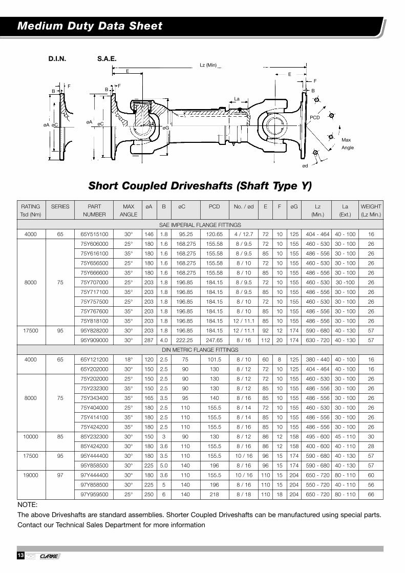
INSPECTION AND MAINTENANCE
Driveshaft inspection should be carried out at regularintervals and it would be reasonable to co-ordinate thiswith the maintenance work on other Vehicle parts. Themaintenance intervals mentioned in the following sectionare only recommendations because maintenanceintervals generally depend on the operating conditions ofthe Vehicle and on practical experience.
Driveshafts are used in a great variety of Industrial plantswith very different operating conditions. We recommendinspections at regular intervals and, if possible,coordinate it with maintenance work on other parts of theequipment. However maintenance work should becarried out once a year at least.
● Check the Flange Bolts for tightness and retightenthem with the prescribed torque. If they needreplacing, Nuts and Bolts of the correct size shouldbe evenly tightened crosswise all round until securelylocked to the recommended torque value. The Boltsshould only be slightly oiled. Lubricants containingMOS2 additives or similar must not be used.
● Check lubrication schedule is being maintained.
● Backlash inspection. By lifting the Driveshaft checkthe Joint and the length compensation for visible ortangible backlash. If there is any perceptible play, theDriveshaft must be repaired.
● Check the Driveshaft for any unusual noise, vibrationor abnormal behaviour and repair the damage, if any.
BOLTING
All inspections must include the checking of the Bolts forthe prescribed tightening torques.
The Bolts should only be slightly oiled. Lubricantscontaining MOS2 additives or similar must NOT be used.
LUBRICATION
The Driveshaft should be greased with a Lithium basedGrease with EP additives.
Grease Nipples must be cleaned before greasing.
The maximum greasing pressure is 15 bar.
There are three greasing areas on the Driveshaft, theUniversal Joints and the Splined Sleeve.
IMPORTANT
When lubricating Universal Joints, ensure that freshGrease exudes from all four Bearing Seals to be certainthat all Bearings have fresh Grease. The lubrication of theSplined Sleeve should be carried out with the Driveshaftfully compressed to prevent excessive axial forcedeveloping.
RE-GREASING INTERVALS Recommended regreasing intervals (unless otherwisespecified by the manufacturer of the Vehicle). Thefollowing maintenance intervals refer to European andcomparable conditions. Other conditions may requireshorter re-lubrication intervals.
LUBRICATIONPROGRAMME JOINTS & SLIDING
(Vehicles) SPLINES
Commercial Vehicles, 10,000 kmBuses on road or
& similarly applied 3 monthsVehicles
Commercial Vehicles 5,000 kmfor on & off road use or& similarly applied 2 months
Vehicles
Commercial & 2,500 kmConstruction Vehicles, or
Earth moving equipment, 1 monthTractors etc. & similarly
applied Vehicles
The recommended lubrication interval for Driveshaftsused in Industrial plants in normal operating conditions isthree months. Unfavourable effects like temperature, dirtand water may necessitate shorter lubricating intervals.We recommend adapting the lubricating intervals to theindividual operating conditions.

Other Products Available
27
Serrated Flanges
Double Joints
Fixed Length Shafts
Highly Flexible CouplingsMechanics Joints
Quick Release Flanges
Component Parts forOther Makes; i.e.
Universal Joints. CentreBearings etc.
Gear Type CouplingsSpecial Mill Spindles

Product Information & Machining CapacityWe’ve got the drive......NDE Clarke Transmissions Ltd - Company Profile
NDE Clarke Transmissions manufacture high quality Driveshafts and
drivelines to most configurations and specifications with either S.A.E. or
D.I.N. standard Flanges for European and U.K. built equipment -
including industrial applications.
NDE Clarke brings to the Driveshafts market a dynamic commercial
approach, complementing substantial driveline skills, thereby producing
a Cardan Shaft manufacturer which offers you the package of quality,
price and service necessary to your business.
This technical manual defines our current standard programme and
provides the technical information to assist the Design Engineer in the
selection and layout of drivelines. It has not been possible to include a
very wide range of special designs which we undertake within the
contents of this manual. We would be pleased if you would contact our
Technical Sales Department now for prompt technical assistance and
pricing. NDE Clarke will offer you a complete
engineering solution.
Quality throughInvestment
REGISTERED
Registered No. FM 28213

HIGH PERFORMANCEUNIVERSAL DRIVESHAFTS
NDE CLARKE TRANSMISSIONS LTDAldbourne Road Works Coventry CV1 4EQ
Tel: +44 (0)24 7622 2272 Fax: +44 (0)24 7625 8499Email : [email protected]
Web: www.ndepower.com
REGISTERED
Certificate No. FM 23551
© NDE Clarke Transmissions Limited Publication No. 05/07
Fole
shill
Roa
d (
B41
13)
Radford R
oad (B4098)
Wid
drin
gton
Roa
d
Aldbourne R
oadK
ingf
ield
Roa
d
San
dy L
ane
Light Lane
Coventry Ring Road (A4053)
Coven
try R
ing
Road
(A40
53)
St. N
icholas Street
Cash’s Lane
Sandy Lane
NDE Clarke Transmissions Ltd.
M6
Junc
tion
3

Voimansiirtokomponentit ja laitekokonaisuudet ovat meille tuttuja, sillä olemme yksi johtavista voimansiirtokomponenttien toimittajista Suomessa. Asiantuntijamme auttavat mielellään löytämään oikeat ratkaisut tarpeisiinne ja pystymme laajan tuotevalikoimamme ja kattavan varasto-ohjelman avulla nopeisiin toimituksiin.
Edustamme kansainvälisesti tunnettuja valmistajia ja tuotemerkkejä – tuotteiden ja toiminnan korkea laatu on yksi toimintamme kulmakivistä. Palvelemme teitä kaikissa voimansiirtoasioissanne yli neljänkymmenen vuoden kokemuksella.
Solutions for power transmission
www.konaflex.fi