Embed Size (px)
Citation preview
Supercomputing for your desktop!
Finite Element Analysis of Ultrasonic Phased Array
Inspections on Anisotropic Welds
Paul ReynoldsPaul ReynoldsWeidlinger Associates IncWeidlinger Associates Inc
Contents
• IntroductionIntroduction
• Anisotropic Weld StructureAnisotropic Weld Structure
• Finite Element Modelling of InspectionFinite Element Modelling of Inspection
• Application of Total Focusing Method Application of Total Focusing Method
(TFM)(TFM)
• Time Reversal Acoustics (TRA)Time Reversal Acoustics (TRA)
• Results of TRA and TFMResults of TRA and TFM
• ConclusionsConclusions
Introduction
• Weld integrity of the upmost importance in Weld integrity of the upmost importance in
modern industrymodern industry
• Exotic materials used more and more Exotic materials used more and more
frequently due to increasing performance frequently due to increasing performance
demandsdemands
• Anisotropic behavior of these complex Anisotropic behavior of these complex
materials make conventional ultrasonic materials make conventional ultrasonic
inspection methods unreliableinspection methods unreliable
Introduction
• Semi-analytical models cannot adequately Semi-analytical models cannot adequately
deal with extensive material boundaries that deal with extensive material boundaries that
exist in such mediaexist in such media
• FEA offers potential for investigating FEA offers potential for investigating
performance new ultrasonic inspection performance new ultrasonic inspection
methods on these structuresmethods on these structures
• Simulated inspection data can be readily Simulated inspection data can be readily
compared to experimental data if availablecompared to experimental data if available
Anisotropic Weld
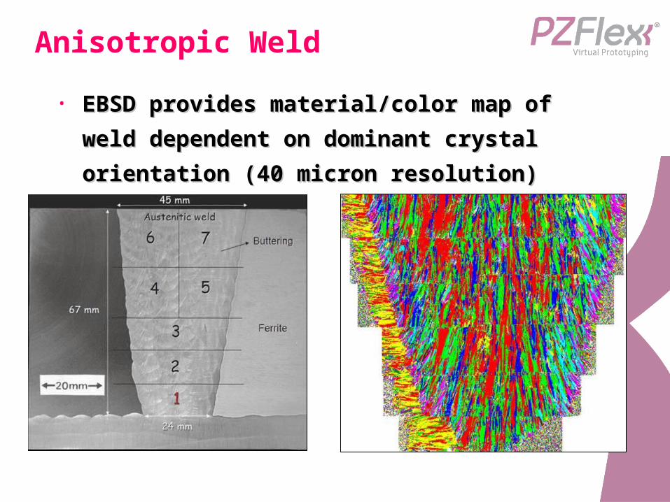
• EBSD provides material/color map of weld EBSD provides material/color map of weld
dependent on dominant crystal dependent on dominant crystal
orientation (40 micron resolution)orientation (40 micron resolution)
Inspection Details
• 128 element piezocermic array:128 element piezocermic array:• 0.5mm ceramic elements0.5mm ceramic elements
• 0.5mm polymer kerf = 1mm pitch0.5mm polymer kerf = 1mm pitch
• 1.5MHz centre frequency1.5MHz centre frequency
• Full Matrix Capture data processingFull Matrix Capture data processing• Transmit on 1 element, receive on all othersTransmit on 1 element, receive on all others
• Repeat for all element to give 128x128 tracesRepeat for all element to give 128x128 traces
• 3mm diameter Side Drilled Hole defect3mm diameter Side Drilled Hole defect
• Array positioned directly on top of weldArray positioned directly on top of weld
• Weld represents join in a water filled pipeWeld represents join in a water filled pipe
FE Inspection
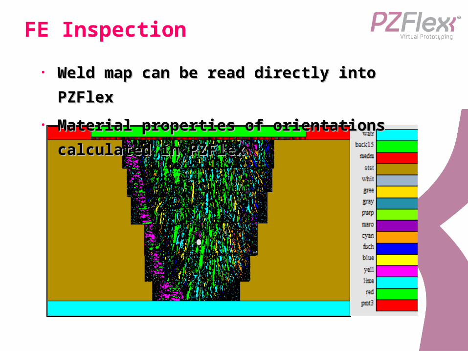
• Weld map can be read directly into Weld map can be read directly into
PZFlexPZFlex
• Material properties of orientations Material properties of orientations
calculated in PZFlexcalculated in PZFlex
FE Details
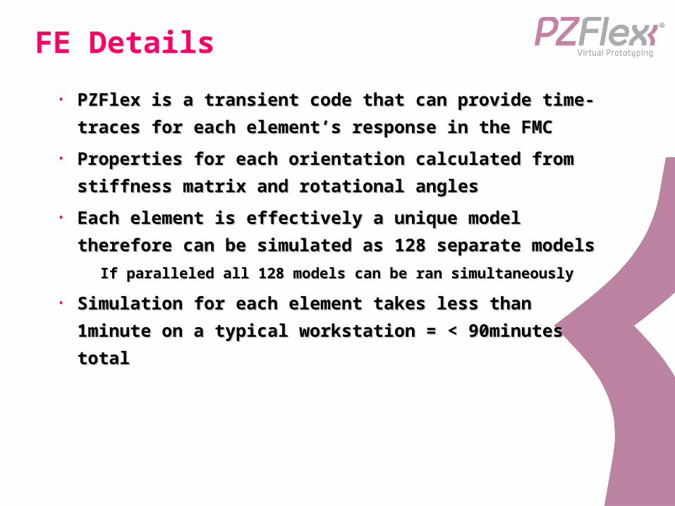
• PZFlex is a transient code that can provide time-PZFlex is a transient code that can provide time-
traces for each element’s response in the FMCtraces for each element’s response in the FMC
• Properties for each orientation calculated from Properties for each orientation calculated from
stiffness matrix and rotational anglesstiffness matrix and rotational angles
• Each element is effectively a unique model Each element is effectively a unique model
therefore can be simulated as 128 separate therefore can be simulated as 128 separate
modelsmodels• If paralleled all 128 models can be ran simultaneouslyIf paralleled all 128 models can be ran simultaneously
• Simulation for each element takes less than Simulation for each element takes less than
1minute on a typical workstation = < 90minutes 1minute on a typical workstation = < 90minutes
totaltotal
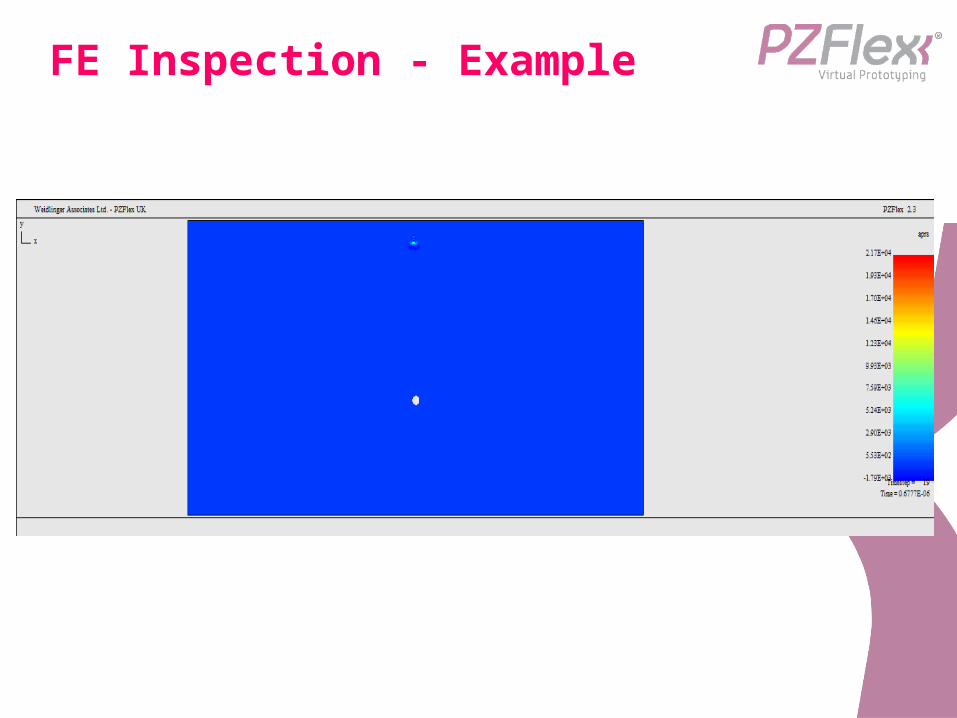
FE Inspection - Example
TFM – Isotropic Delays
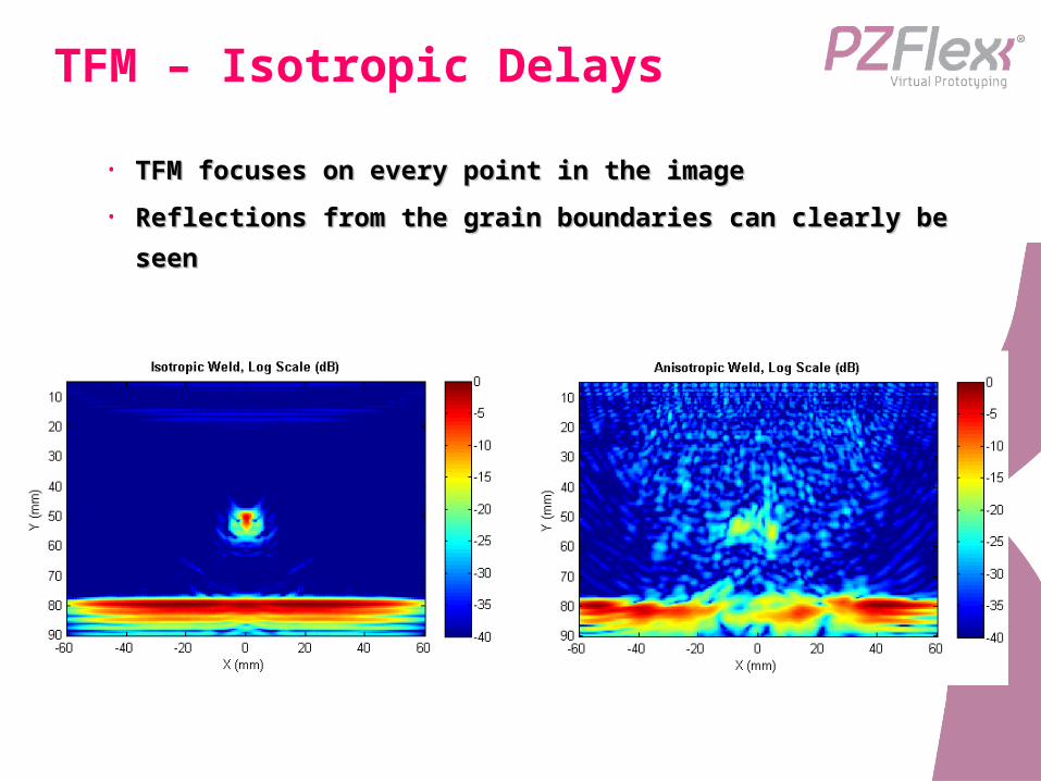
• TFM focuses on every point in the imageTFM focuses on every point in the image
• Reflections from the grain boundaries can clearly be Reflections from the grain boundaries can clearly be
seenseen
TRA – Delay correction
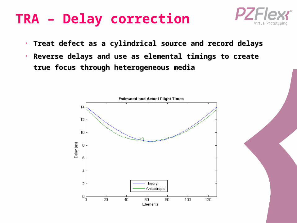
• Treat defect as a cylindrical source and record delaysTreat defect as a cylindrical source and record delays
• Reverse delays and use as elemental timings to create Reverse delays and use as elemental timings to create
true focus through heterogeneous mediatrue focus through heterogeneous media
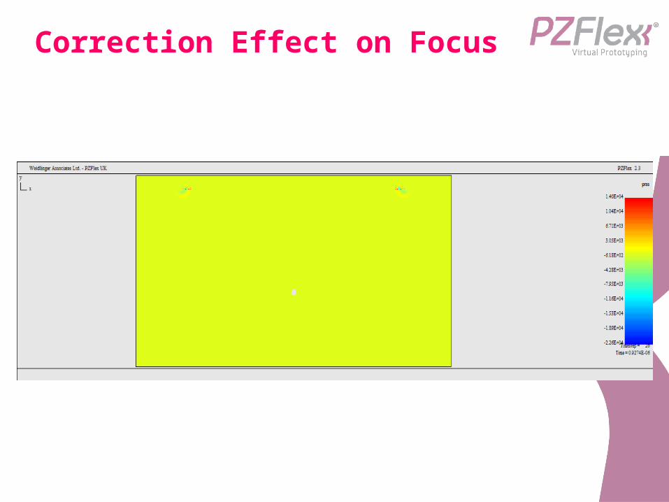
Correction Effect on Focus
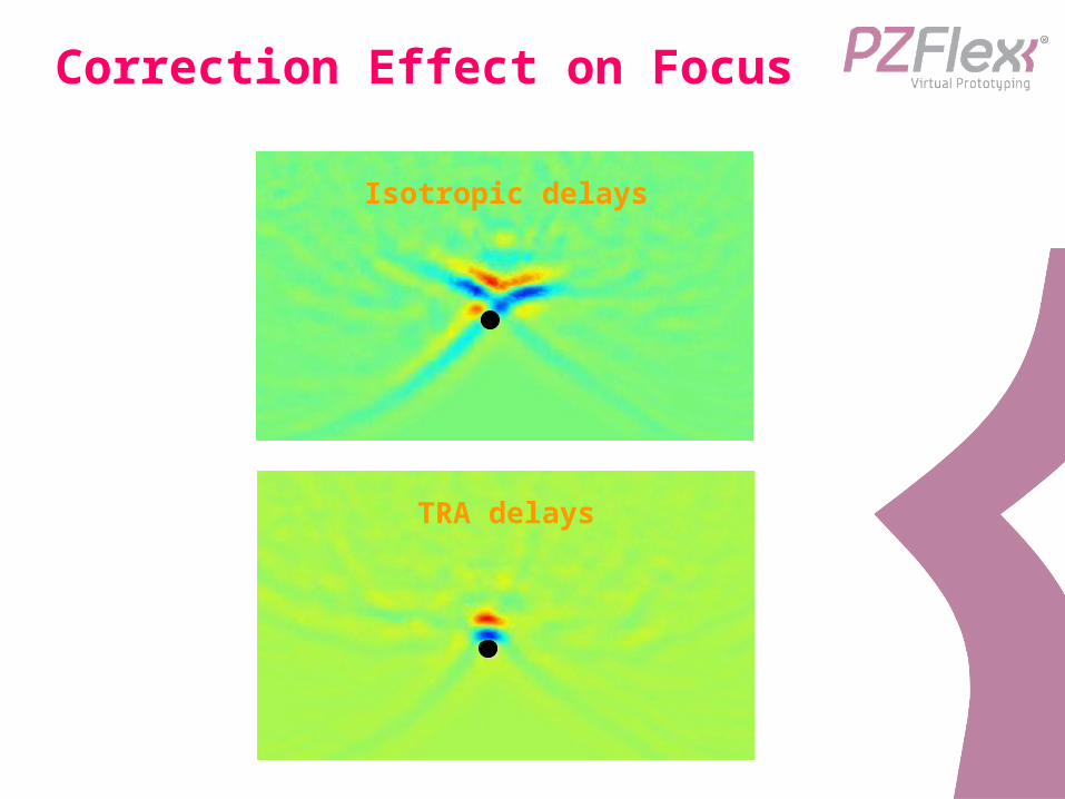
Correction Effect on Focus
TRA delays
Isotropic delays
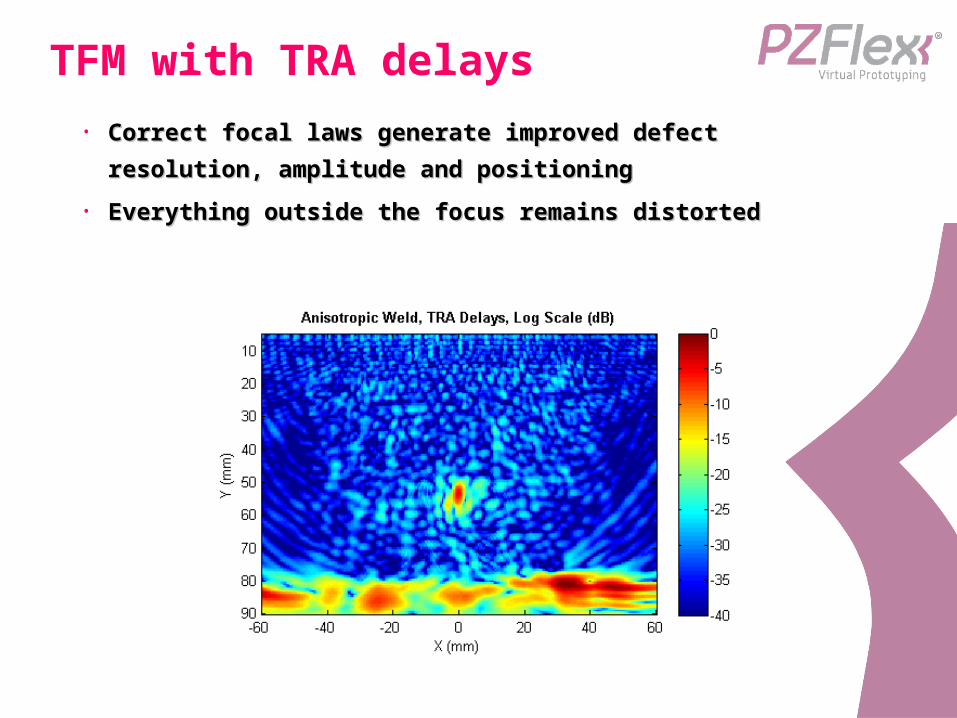
TFM with TRA delays
• Correct focal laws generate improved defect Correct focal laws generate improved defect
resolution, amplitude and positioningresolution, amplitude and positioning
• Everything outside the focus remains distortedEverything outside the focus remains distorted
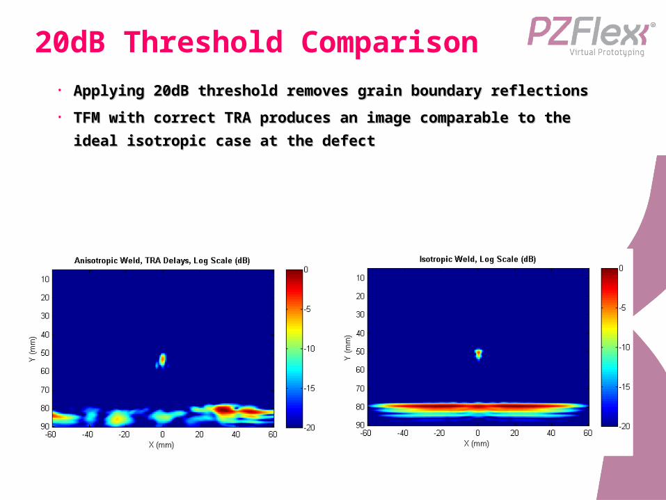
20dB Threshold Comparison• Applying 20dB threshold removes grain boundary reflectionsApplying 20dB threshold removes grain boundary reflections
• TFM with correct TRA produces an image comparable to the TFM with correct TRA produces an image comparable to the
ideal isotropic case at the defectideal isotropic case at the defect

Conclusions
• Paul – thought I’d let you draw your own Paul – thought I’d let you draw your own
conclusions as you’ll be presenting it.conclusions as you’ll be presenting it.