Embed Size (px)
Citation preview
1
A Handoff Architecture with Relay Agent in Nested Mobile Networks
1Jae Kul Lee, 2Choong Seon Hong1,2 School of Electronics and Information, Kyung Hee University
Korea [email protected], [email protected]
AbstractUnder the circumstance of traditional MIPv6 and mobile networks, a Correspondent Node(CN) always attempts to send a packet to the Mobile Node(MN) via only it's own Home Agent(HA) at the first communication, while the packet in nested mobile network is forwarded via all HA referring to Mobile Router(MR) in tree. Two problems occur in this scenario; one is inefficient routing via several HAs, the other lies in waste of transmission resource and delay of registration process caused by change of nested mobile network’s topology. Therefore, we propose Mobile Relay Agent (MRA) to support effective routing by local mobility management. Our proposal establishes direct path from Top Level Mobile Router(TLMR) to CNs and its HA that could achieve smaller handoff latency by localizing the update messages within a restricted scale over nested mobile network.Keywords: NEtwork MObility (NEMO), Nested Mobile Network, Handoff, Relay

2
IntroductionThe evolution of information technology has enabled a mobile object such as person, car, bus, train, airplane, or ship to carry a plethora of information device
Although Mobile IPv6 can be considered as a solution for the problem, it does not support in the situation
Routing is inefficient in nested mobile networks with several subnets
This paper proposes an architecture and element to support packet routing for mobile networks
1. Introduction
The evolution of information technology has enabled a mobile object such as person, car, bus, train, airplane, or ship to carry a plethora of information devices. They also carry another those with information devices and many kinds and many kinds of information devices are installed in them.[1]Traditional mobility support usually provides internet connectivity for mobile hosts. In contrast, network mobility support should supply that to an entire network composed by one or more subnets. The mobile network can change it’s point of attachment to Internet.[2] Mobility support scheme is researched actively in NEMO(NEtwork MObility) that is WG(working group) of IETF(Internet Engineering Task Force).Mobile networks have three issues. The first is address management in mobile network. For example, Foreign network should assign new CoA to node or MR(Mobile Router) changing point of attachment to keep connecting to internet. The second one is to secure security from it. The mobile node is authenticated its HA and CNs but those have no guarantee that the Mobile Node is allowed to send a binding update for the home address specified in the Binding update. It is required that HA authorize a binding sent with PSBU(Prefix Scope Binding updates)[2]. The final one is issue of route optimization. All the Packets sent by NEMO, HA and CN will be passed via the HAs of all the MRs on their path
3
Packet Format of the Binding Update
LifetimeSub-Options
Sequence NumberPrefix LengthA|H|R|D|P|Rervd
Option LengthOption Type231680
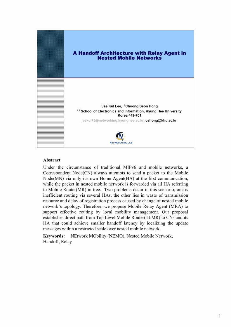
Table 1. Binding update option format
MONET Prefix
Prefix LengthSub-Option LenSub-Option Type
231680
Table 2. MONET prefix sub-option
2.1 Binding update for mobile networkLately, a recent paper[1] and IETF draft[2] proposed extension of Mobile IPv6 using PSBU(Prefix Scope Binding update) for NEMO. Instead of establishing a one-to-one relationship between a home address and a CoA, the binding refered to as PSBUs establishes a many- to-one relationship between the set of nodes that share the same MONET Prefix and a CoA, as described in [2]. In NEMOs, they use binding update that composes of CoAand the MONET Prefix instead of the full 128-bits IPv6 home address. New flag is added in binding update option of Mobile IPv6 to support PSBU. It means BU has new sub-option with MONET prefix. MR sends PSBU to HA and CNs which communicate with LFN(Local Fixed Node)s. PSBU enables Node receiving it to use it as net mask. Existing address conforms with MONET prefix. The direct path between MONET and CN communicatingwith several LFNs is set up by a single registration with MONET prefix.
4
Operation of main componentsCorrespondent node operation
Checks validity of binding updateCreates a new entry in binding cacheLooks for entry corresponding to the destination address
Home agent operationChecks validity of binding updateTunnels the packet to the CoA coincide with a prefix
Mobile router operationSends the prefix scope binding update to its HADecapsulates packet and send packet to the original destinationSends prefix scope binding update to the original sender
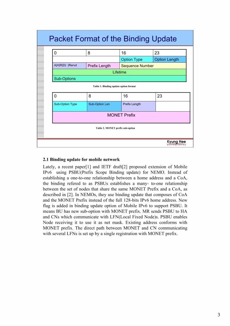
2.2 Operation of main components2.2.1 Correspondent Node OperationWhen correspondent node receive binding update, it has three procedures. First, it receives BU from either MRs or MNs. Second, the CN checks validity. If P flag is set, it should include MONET Prefix Sub-Option in binding update. If the binding update is valid, the CNcreates a new entry in binding cache. When the CN attempts to send packets, it looks for entry corresponding to the destination address in the binding cache. If there is CoA equal to destination address, CN send packet to CoA.2.2.2 Home Agent OperationIf the HA receives a binding update from a MR in a mobile network, the HA checks validity. It stores the binding in the Binding Cache. When HA receives a packet, HA checks whether destination address coincide with a prefix of a binding in binding cache or not. If that is equal, HA tunnels the packet to the CoA.2.2.3 Mobile Router OperationThe prefix scope binding update is sent by MR to its HA, its own CNs and CNs of the LFNs. The MR sets the “P” flag in binding update and adds a MONET Sub-Option with MONET Prefix. If the MR sends a binding update to its HA, tunnel is set up between MR and its HA. If the MR receive encapsulated packet, it should perform two things. The first is that MR should decapsulate packet and send packet to the original destination. The second, MR should send prefix scope binding update to the original sender because Receiving an encapsulated packet tunneled from the MR’s HA means that original sender don’t know information of mobility for MONET.[1][2]
5
Scenario of mobile network
::
CNStationary Network
HAMR1
FR
FR
FR
HAMR2
MR2
FRFR
Mobile Network(e.g., Train)
LFN1 LFN2
MR1Mobile
Network(e.g., Person)
Routing Table :Prefix2 -> MR2Prefix3 -> MR2
Binding Cache :MR2 -> CoAMR2
Prefix2 -> CoAMR2
Prefix3 -> CoAMR2
::
Routing Table :Prefix1 -> MR1
Binding Cache :MR1 -> CoAMR1
Prefix1 -> CoAMR1
(1)
(2)
(4 )
(3 )
(5 )
Figure 1. Traditional nested mobile network
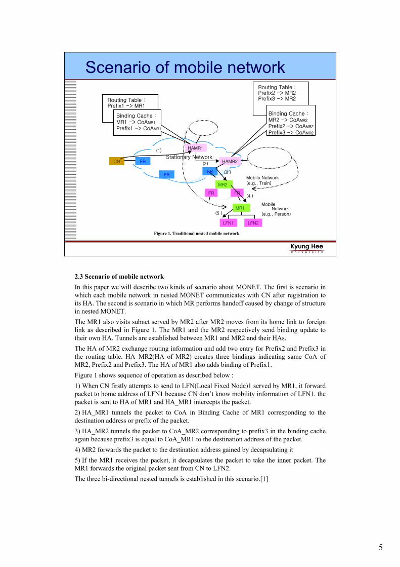
2.3 Scenario of mobile networkIn this paper we will describe two kinds of scenario about MONET. The first is scenario in which each mobile network in nested MONET communicates with CN after registration to its HA. The second is scenario in which MR performs handoff caused by change of structure in nested MONET.The MR1 also visits subnet served by MR2 after MR2 moves from its home link to foreign link as described in Figure 1. The MR1 and the MR2 respectively send binding update to their own HA. Tunnels are established between MR1 and MR2 and their HAs.The HA of MR2 exchange routing information and add two entry for Prefix2 and Prefix3 in the routing table. HA_MR2(HA of MR2) creates three bindings indicating same CoA of MR2, Prefix2 and Prefix3. The HA of MR1 also adds binding of Prefix1. Figure 1 shows sequence of operation as described below :1) When CN firstly attempts to send to LFN(Local Fixed Node)1 served by MR1, it forward packet to home address of LFN1 because CN don’t know mobility information of LFN1. the packet is sent to HA of MR1 and HA_MR1 intercepts the packet.2) HA_MR1 tunnels the packet to CoA in Binding Cache of MR1 corresponding to the destination address or prefix of the packet.3) HA_MR2 tunnels the packet to CoA_MR2 corresponding to prefix3 in the binding cache again because prefix3 is equal to CoA_MR1 to the destination address of the packet.4) MR2 forwards the packet to the destination address gained by decapsulating it5) If the MR1 receives the packet, it decapsulates the packet to take the inner packet. The MR1 forwards the original packet sent from CN to LFN2.The three bi-directional nested tunnels is established in this scenario.[1]
6
Handoff within the nested mobile network
Figure 2. Handoff within the nested mobile network
CNStationary Network
HAMR1
FR
LFN1 LFN2
MR1
FR
MR2
FRFR
HAMR2
Mobile Network(e.g., Train)
:
Routing Table :Prefix2 -> MR2Prefix3 -> MR2
Binding Cache :MR2 -> CoAMR2
Prefix2 -> CoAMR2
Prefix3 -> CoAMR2
:
Prefix 3Prefix 2
Routing Table :Prefix1 -> MR1
Binding Cache :MR1 -> CoAMR1
Prefix1 -> CoAMR1
Prefix 1
FR
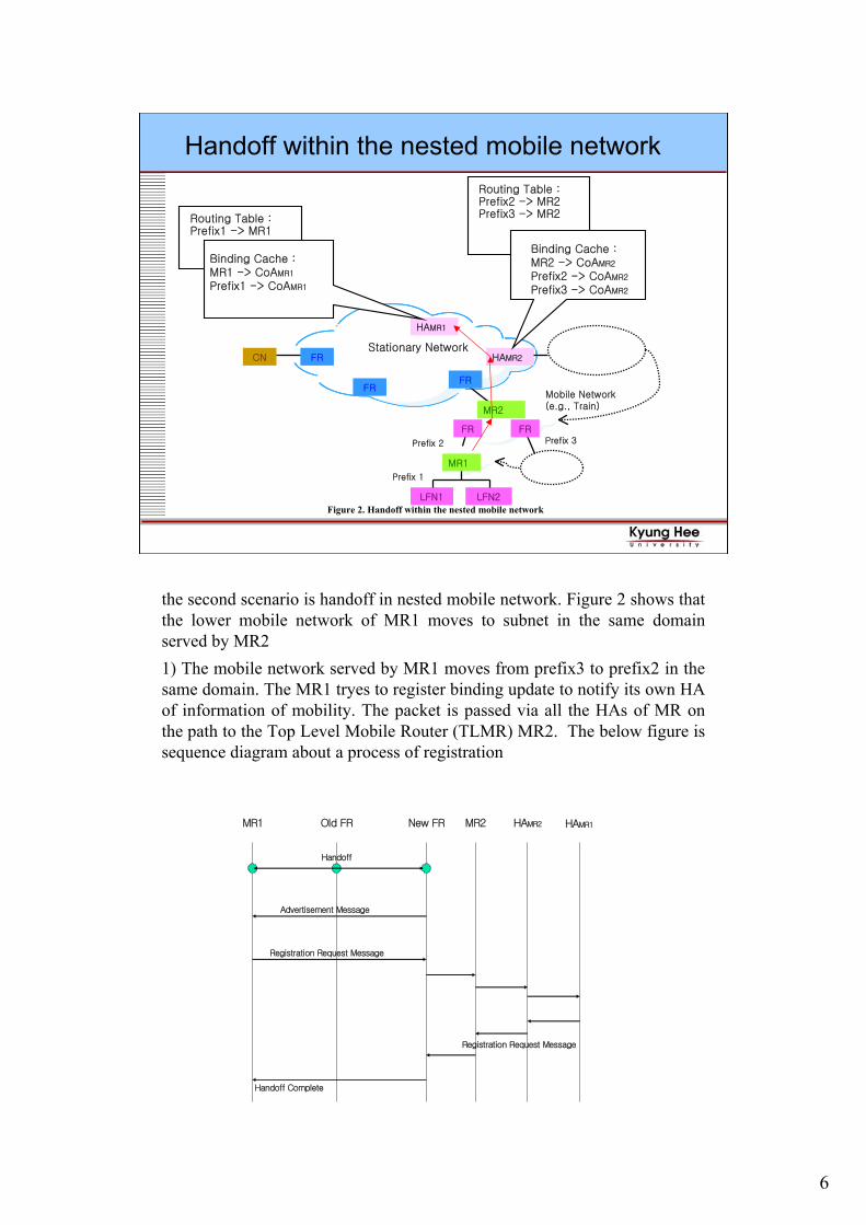
the second scenario is handoff in nested mobile network. Figure 2 shows that the lower mobile network of MR1 moves to subnet in the same domain served by MR2 1) The mobile network served by MR1 moves from prefix3 to prefix2 in the same domain. The MR1 tryes to register binding update to notify its own HA of information of mobility. The packet is passed via all the HAs of MR on the path to the Top Level Mobile Router (TLMR) MR2. The below figure is sequence diagram about a process of registration
MR1 Old FR New FR MR2 HAMR1
Handoff
Advertisement Message
Registration Request Message
Registration Request Message
Handoff Complete
HAMR2

7
Proposed ArchitectureMRA(Mobile Relay Agent)
Role
Upon receiving a packet, the MRA set it’s address in this
packet and relays it to next MRA or destination
Manage cache to support for mobile node or networks
Assignment
MRA is dynamically assigned mobile router on the path
when mobile node or router sends Binding Update
massage to Home Agent
3. Proposal for nested mobile networkThis paper requests mobile router to have additional functions for nested mobile network. We shall refer to such a mobile router as a Mobile Relay Agent(MRA). With no nested tunnels optimization, we would have three bi-directional nested tunnels. In the paper Top Level MRA establish the direct route to CNs and HAs. For example, if MRA receives BU from mobile network of lower level, MRA replaces CoA of BU with its own CoA and relay BU to the upstream MRA. That allows route to be optimized in the nested mobile network and avoids size of packet to increase by the overhead tunnels. In addition, if tree of nested mobile network has a change, existing method requests MR to send BU to its HA through the overlaid tunnels. In contrast, the proposed method completes fast handoff by only registering BU to the upstream MRA. Existing paper[3] proposed route optimization in the nested mobile network but that has three problems. The first, that cause increase of packet size by routing header. The second, when a topology in the tree changes, MR should send an RRH heartbeat similar to BU to its own HA. MRA is dynamically assigned to mobile router on the path when mobile node or router send Binding update message to Home Agent.

8
Operation scenario in proposed Architecture
CNStationary Network
HAMR1
FR
LFN1 LFN2
MTA1
FR
FR
MTA2
FRFR
HAMR2
Mobile Network(e.g., Train)
Mobile Network(e.g., Person)
:
Routing Table :Prefix2 -> MR2Prefix3 -> MR2
:
(3)
(4)
(5 )
(6 ) Prefix 1
Prefix 3
Prefix 2Binding Cache :MR1 -> CoAMTA1
Prefix1 -> CoAMTA1(1 )
Routing Table :Prefix1 -> MR1
Binding Cache :MR1 -> CoAMTA2
Prefix1 -> CoAMTA2
(2)
Binding Cache :MR2 -> CoAMTA2
Prefix2 -> CoAMTA2
Prefix3 -> CoAMTA2
Figure 3. Scenario in nested mobile network with MRA
3.1 Scenario for mobility management of the mobile networkThe MR1 also visits subnet served by MRA2 after mobile network of MRA2 moves from its home link to foreign link. The MRA1 and the MRA2 respectively send binding update to their own HAs. Figure 3 shows sequence of operation as described below :1) MRA2 sends binding update message to its HA to notify information of new location after visiting foreign link.2) MRA1 also forward BU with home address option to MRA2 on the path destined to its HA after mobile network represented by it move to subnet of MRA2. If MRA2 receive BU from MRA1, the MRA checks its destination option header and create a binding cache entry for MRA1 (home address of MRA1 -> Care-of-address of MRA1). MRA2 replaces the CoA of MRA in the binding update with its own CoA, then relays BU to HAs, CNs and the MRA of upper level.3) If CN newly attempts to send a packet to LFN1, it is forwarded to home address of LFN1 because CN don’t know information of new location.4) HA of MRA intercepts the packet destined to LFN1 and search the entry equal to that in the binding cache. Then HA forwards packet encapsulated by CoA of MRA2.5) When MRA2 receives packet from HA of MRA, it has three procedure. The first, MRA2 decapsulates the packet to gain the inner packet. The second, MRA2 searches entry equal to the inner packet. The final, MRA2 encapsulates the packet to MRA1 and sends it.6) MRA decapsulates the packet to gain original packet and forwards it to LFN1.
9
Handoff in proposed Architecture
CN
Stationary Network
HAMR1
FR
LFN1 LFN2
MRA1
FR
FR
MRA2
FRFR
HAMR2
Mobile Network(e.g., Train)
:
Routing Table :Prefix2 -> MR2Prefix3 -> MR2
:
Prefix 3
Prefix 2Binding Cache :MR1 -> CoAMTA1
Prefix1 -> CoAMTA1
Routing Table :Prefix1 -> MR1
Binding Cache :MR1 -> CoAMRA2
Prefix1 -> CoAMRA2
Binding Cache :MR2 -> CoAMRA2
Prefix2 -> CoAMRA2
Prefix3 -> CoAMRA2
Figure 4. Handoff within the nested mobile network
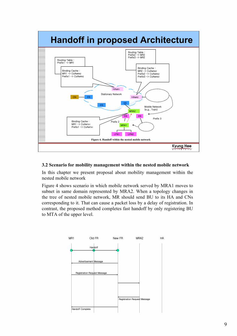
3.2 Scenario for mobility management within the nested mobile networkIn this chapter we present proposal about mobility management within the nested mobile network Figure 4 shows scenario in which mobile network served by MRA1 moves to subnet in same domain represented by MRA2. When a topology changes in the tree of nested mobile network, MR should send BU to its HA and CNscorresponding to it. That can cause a packet loss by a delay of registration. In contrast, the proposed method completes fast handoff by only registering BU to MTA of the upper level.
MR1 Old FR New FR MRA2 HA
Handoff
Advertisement Message
Registration Request Message
Registration Request Message
Handoff Complete
10
Simulation(1)
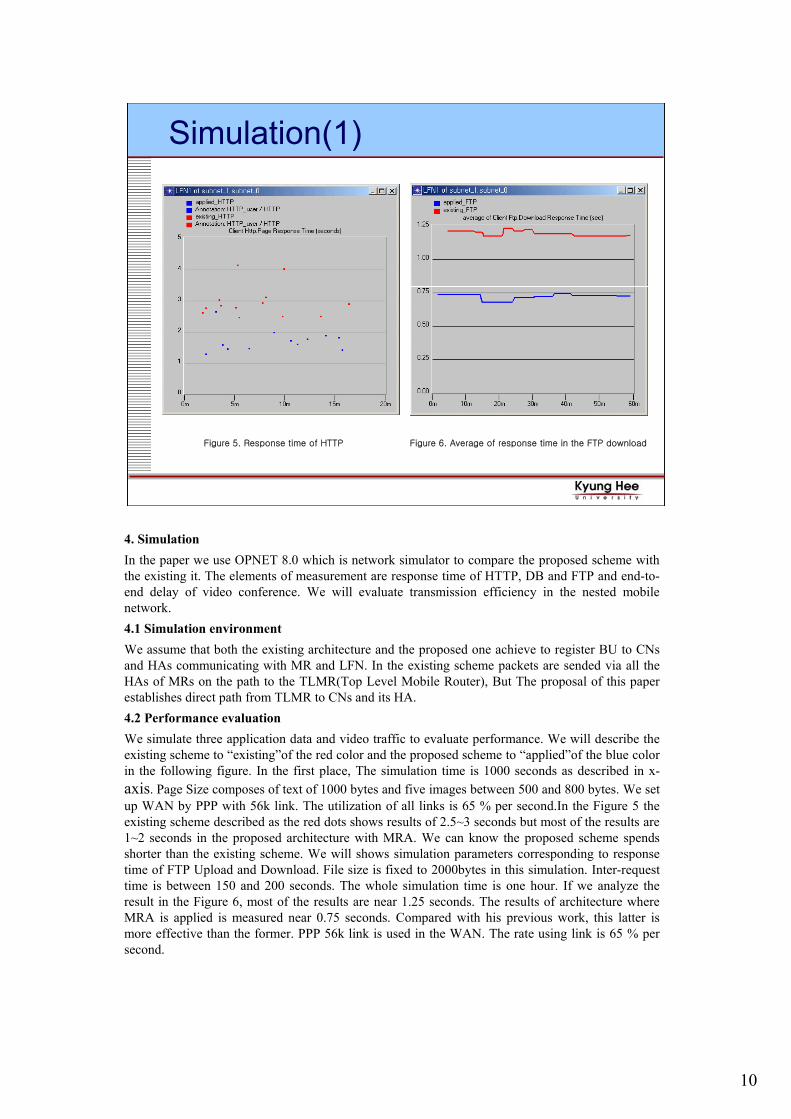
Figure 5. Response time of HTTP Figure 6. Average of response time in the FTP download
4. SimulationIn the paper we use OPNET 8.0 which is network simulator to compare the proposed scheme with the existing it. The elements of measurement are response time of HTTP, DB and FTP and end-to-end delay of video conference. We will evaluate transmission efficiency in the nested mobile network.4.1 Simulation environmentWe assume that both the existing architecture and the proposed one achieve to register BU to CNsand HAs communicating with MR and LFN. In the existing scheme packets are sended via all the HAs of MRs on the path to the TLMR(Top Level Mobile Router), But The proposal of this paper establishes direct path from TLMR to CNs and its HA.4.2 Performance evaluationWe simulate three application data and video traffic to evaluate performance. We will describe the existing scheme to “existing”of the red color and the proposed scheme to “applied”of the blue color in the following figure. In the first place, The simulation time is 1000 seconds as described in x-axis. Page Size composes of text of 1000 bytes and five images between 500 and 800 bytes. We set up WAN by PPP with 56k link. The utilization of all links is 65 % per second.In the Figure 5 the existing scheme described as the red dots shows results of 2.5~3 seconds but most of the results are 1~2 seconds in the proposed architecture with MRA. We can know the proposed scheme spends shorter than the existing scheme. We will shows simulation parameters corresponding to response time of FTP Upload and Download. File size is fixed to 2000bytes in this simulation. Inter-request time is between 150 and 200 seconds. The whole simulation time is one hour. If we analyze the result in the Figure 6, most of the results are near 1.25 seconds. The results of architecture where MRA is applied is measured near 0.75 seconds. Compared with his previous work, this latter is more effective than the former. PPP 56k link is used in the WAN. The rate using link is 65 % per second.
11
Simulation(2)
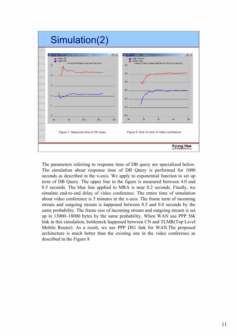
Figure 8. End-to-end of Video conferenceFigure 7. Response time of DB Query
The parameters referring to response time of DB query are specialized below. The simulation about response time of DB Query is performed for 1000 seconds as described in the x-axis. We apply to exponential function to set up term of DB Query. The upper line in the figure is measured between 4.0 and 0.5 seconds. The blue line applied to MRA is near 0.2 seconds. Finally, we simulate end-to-end delay of video conference. The entire time of simulation about video conference is 5 minutes in the x-axis. The frame term of incoming stream and outgoing stream is happened between 0.5 and 0.8 seconds by the same probability. The frame size of incoming stream and outgoing stream is set up in 13000~18000 bytes by the same probability. When WAN use PPP 56k link in this simulation, bottleneck happened between CN and TLMR(Top Level Mobile Router). As a result, we use PPP DS1 link for WAN.The proposed architecture is much better than the existing one in the video conference as described in the Figure 8

12
ConclusionThis paper proposes MRA that supports route optimization
in the nested mobile network
Mobile IPv6 with MRA allows top-level Router on a mobile
network to directly communicate with CN
The simulation corresponding to response time of HTTP,
FTP, DB and end-to-end delay of video conference shows
that the proposed method is much better than the existing
one
5. ConclusionMobile IP supports route optimization for host but there is the inefficient route to flow via the HAs of all the MRs on their path within the Mobile Network. MR should send BU to its HA as soon as change of architecture happen in the nested mobile network. It takes long delay to complete handoff. This paper proposed MRA so that mobile routers can support such problems in nested mobile network. The proposed architecture establishes direct path from TLMR to CNs and corresponding its HA. This scheme also achieves fast handoff by only registering BU to the upper level MRA. The Simulation to response time of HTTP, FTP, DB and end-to-end delay of video conference shows that the proposed method is much better than the existing oneAcknowledgementThis work was supported by a grant No. R05-2003-000-12193-0 from Korea Science & Engineering Foundation.
References[1] Ichiro OKAJIMA, Narumi Umeda, Yasushi YAMAO, “Architecture and Mobile IPv6 Extensions Supporting Mobile Networks In Mobile Communications,” Vehicular Technology Conference, 2001. VTC 2001 Fall. IEEE VTS 54th, Volume: 4, 2001[2] Alexis Olivereau, Ludovic Bellier, Claude Castelluccia, "Mobile Networks Support in Mobile IPv6," Internet Draft, IETF, March 2002[3] P. Thubert, M. Molteni, "IPv6 Reverse Routing Header and its application to Mobile Networks," Internet Draft, IETF, June 2002[4] Seisho Yasukawa, Jun Nishikido, Komura Hisashi, “Scalable Mobility and QoS Support Mechanism for IPv6-based Real-time Wireless Internet Traffic,” Global Telecommunications Conference, 2001. GLOBECOM '01. IEEE, Volume: 6, 2001[5] Eva Gustafsson, Annika Jonsson, Charles E. Perkins, "Mobile IPv4 Regional Registration," Internet Draft, IETF, October, 2002[6] Timothy J. Kniveton, Jari T. Malinen, Vijay Devarapalli, Charles E. Perkins, “Mobile Router Support with Mobile IP” Internet Draft, IETF, July 2002[7] S. Deering, R.Hinden, “Internet Protocol Version 6 (ipv6) Specification,” RFC2460, IETF, December 1998[8] D. Johnson, C. Perkins, J. Arkko, "Mobility Support in IPv6," Internet Draft, IETF, February 26, 2003[9] A. Conta, S. Deering, "Generic Packet Tunneling in IPv6 Specification," RFC2473, IETF, December 1998[10] C. Perkins, "IP Mobility Support," RFC2002, IETF, October 1996