Embed Size (px)
Citation preview


www.RosenbergerAP.com
INTRODUCTION
Rosenberger Hochfrequenztechnik GmbH & Co. was founded in Germany in 1958 and ranks among the leading manufacturers of high-speed interconnect solutions worldwide. To serve the continuous growth and demand of the global market, Rosenberger Asia Paci c lectronic Co., td. was established in China in 199 . ith its long tradition of e cellence and providing creative solutions, Rosenberger Asia Paci c has e celled and earned an outstanding reputation in the Asia Paci c region.
Rosenberger Asia Pacific provides products and solutions for Telecommunication, Automotive lectronics, nformation Technology, Test & easurement, Aviation, and edical & ndustries.
A sales network covering the entire Asia Paci c region generates an annual turnover close to 5 million . Reliability and competitiveness are the cornerstones of this sustainable growth, resulting in long term partnerships with most of the leading companies in their respective industries.
Rosenberger HQ, Bavaria, Germany

A
B
C
www.RosenbergerAP.com
Rosenberger Asia Pacific maintains modern manufacturing and R& base locations in Bei ing, unshan, hanghai, and ongguan in China and ew elhi & Goa in ndia, the largest of its kind in the Asia Paci c Region. Rosenberger Asia Paci c is
an 9 1 quality system, 1 1 environmental system, and T 1 9 9 automotive industry system certi ed company. quipped with advanced machining, electronic plating, assembly and testing centers and staffed by a large group of more than
R& engineers, Rosenberger Asia Pacific has developed first class production assembly lines and e ercises stringent product and quality control.
Presently, Rosenberger Asia Paci c maintains a far reaching network of R& , Production, ales and ervice which e tends to the whole Asia Paci c and iddle ast area. or years Rosenberger has established its brand all over the world. n the future, Rosenberger Asia Paci c will continue to provide e cellent product solutions and services for its customers in the entire region.
A Bei ing Headquarters, R& , and Production
B unshan, iangsu R& and Production
C Pudong, hanghai R& and Production
ndia R& and Production
ongguan R& and Production

www.RosenbergerAP.com
MISSION STATEMENT
CORE VALUE• alue nnovation• Customer ocus• ustainable Growth• ocial Responsibility
• esign, manufacture and deploy total solutions for telecommunication networks worldwide• Create value for our customers through innovative products, customized services and cost
effective solutions• Maintain the highest quality standards, state-of-the-art manufacturing facilities and employ
reliable supply chain management to achieve and e ceed customer e pectations• Be socially responsible to our community and environment • Be committed to employee's personnel development

www.RosenbergerAP.com
PRODUCTPORTFOLIOS
Antenna ystemsActive Systems Passive ystems
eeder ystemsMicrowave Backhaul olutionsR n-cabinet olutionsPassive ntermodulation Measurement ystems
TTA TTH ptical iber olutionsP iber ptic utdoor Plant olutions
n-building ptical etwork Connectivity olutionsow requency Cables and Componentsetwork ptimization ervices
Premise etwork Cabling Productsata Center Cloud Computing olutions
ntelligent nfrastructure Management ystem
Test CablesPrecision ConnectorsCalibrationsAccessories and Tools
A RA Connectors and Cable AssembliesH ® ystem
on-Magnetic R Connectors on-Magnetic R Cable Assembliesata R Power C Hybrid Connectors and Assemblies
Customized ata Power Connectivity ystemiber ptic Connectivity Products
Telecommunication
IT/Data Communication
Testing and Measurement
Automotive
Medical & Industries

CONTENT
ROSENBERGER NETWORK OPTIMIZATION TECHNOLOGY ————————————————————————————————————————
OFF-AIR REPEATER SOLUTION————————————————————————————————————————
P C R
————————————————————————————————————————
M M P R R
————————————————————————————————————————
H GH P R R
————————————————————————————————————————
FIBER DAS SOLUTION————————————————————————————————————————
MART P
————————————————————————————————————————
H GH P R B R T - R
————————————————————————————————————————
P R B R T -RA A T
————————————————————————————————————————
TRA T A B R PT CA R P AT R
————————————————————————————————————————
OMT&NMS————————————————————————————————————————
ROSENBERGER SERVICE————————————————————————————————————————
8
9
1
11
1
15
16
18
19
22

0605
WIRELESS COVERAGE / CAPACITY ENHANCEMENT SOLUTIONS
ROSENBERGER WIRELESS SOLUTION

OUTLINE
Rosenberger s ff-air repeaters are designed to support multi-mode, multi-operator applications for use in blind spot coverage, quick deployment requirements, and areas without backhaul facilities for base station.
Based on software de ned radio R technology, Rosenberger s ff-air repeaters covers the global cellular frequency band from 698MHz to 269 MHz , and supports wide range output powers from 1 dBm to dBm with total network monitoring M capabilities.
Quick deployment solution for blind spot coverage
Off-air Repeater Series
P C R
M M P R R ,
H GH P R R
M M P R R ,
H GH P R R
M M P R R ,
H GH P R R

Product Overview
Application Scenario Block Diagram
PICO Series
Main Features
• Typical 85dB gain with integrated design offering e ceptional
coverage
• Typical 6 dB out band re ection to prevent unwanted
interference from outdoor or from other operators
• Variable sub-bands to support multi-operator applications
with variable instantaneous bandwidth to support evolving
network requirements
• C function adapts to the time-varying isolation environment
and provides optimized signal coverage at all times
Electrical Speci cationsplink ownlink
requency MHz
- 8 58-8
88 -915 925-96
1 1 -1 85 18 5-188
192 -198 211 -21
25 -25 262 -269
698- 16 28- 6
- 8 6- 56
81 -8 9 859-89
1 1 -1 55 211 -2155
185 -1915 19 -1995
2 5-2 15 2 5 -2 6
R utput Power dBm 1 15 2 2 1 15 2 2
Typical ystem Gain dB 85 85
V R 2. 2.
Typical oise igure dB 8 8
Attenuator Range dB
Mec anical Speci cationsPower upply C with e ternal adaptor
Ports MA -
perating Temperature -25 ºC to +55 ºC
ngress Protection P5 P65
Software Speci cationsocal Control thernet port Via A B
Remote Control ireless Modem
Monitor Unit and Power DC INRJ45
A/D
D/A
D/A
A/D
A/D
D/A
D/A
A/D
System 1
System 2
DL LNA
UL HPA
DL LNA
UL HPA
A/D
D/A
D/A
A/D
DL LNA
UL HPA
DL LNA
UL HPA
DL LNA
UL HPA
DL LNA
UL HPA
FP
GA
System 3
Com
bine
r
Com
bine
r
DT MT
0807
Product Overview
Application Scenario Block Diagram
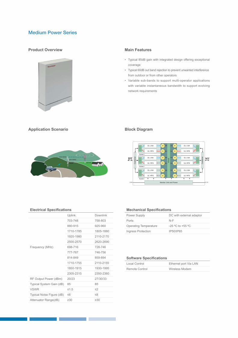
Medium Power Series
Main Features
• Typical 85dB gain with integrated design offering e ceptional
coverage
• Typical 6 dB out band re ection to prevent unwanted interference
from outdoor or from other operators
• Variable sub-bands to support multi-operator applications
with variable instantaneous bandwidth to support evolving
network requirements
Electrical Speci cationsplink ownlink
requency MHz
- 8 58-8
88 -915 925-96
1 1 -1 85 18 5-188
192 -198 211 -21
25 -25 262 -269
698- 16 28- 6
- 8 6- 56
81 -8 9 859-89
1 1 -1 55 211 -2155
185 -1915 19 -1995
2 5-2 15 2 5 -2 6
R utput Power dBm 2 2 2
Typical ystem Gain dB 85 85
V R 1.5 2
Typical oise igure dB 6 8
Attenuator Range dB
Mec anical Speci cationsPower upply C with e ternal adaptor
Ports -
perating Temperature -25 ºC to +55 ºC
ngress Protection P5 P65
Software Speci cationsocal Control thernet port Via A
Remote Control ireless Modem
Monitor Unit and Power DC INRJ45
A/D
D/A
D/A
A/D
A/D
D/A
D/A
A/D
System 1
System 2
DL LNA
UL HPA
DL LNA
UL HPA
A/D
D/A
D/A
A/D
DL LNA
UL HPA
DL LNA
UL HPA
DL LNA
UL HPA
DL LNA
UL HPA
FPG
A
System 3
Com
bine
r
Com
bine
r
DT MT

1009
Product Overview
Application Scenario Block Diagram
High Power Series
Main Features
• Typical 9 dB gain with integrated design offering e ceptional
coverage
• Typical 6 dB out band re ection to prevent unwanted interference
from outdoor or from other operators
• Variable sub-bands to support multi-operator applications
with variable instantaneous bandwidth to support evolving
network requirements
• C function adapts to the time-varying isolation environment
and provides optimized signal coverage at all times
Electrical Speci cationsplink ownlink
requency MHz
- 8 58-8
88 -915 925-96
1 1 -1 85 18 5-188
192 -198 211 -21
25 -25 262 -269
698- 16 28- 6
- 8 6- 56
81 -8 9 859-89
1 1 -1 55 211 -2155
185 -1915 19 -1995
2 5-2 15 2 5 -2 6
R utput Power dBm 23 3
Typical ystem Gain dB 9 9
V R 1.5 1.5
Typical oise igure dB 6 6
Attenuator Range dB 3 3
Mec anical Speci cationsPower upply AC
Ports -
perating Temperature -25 ºC to +55 ºC
ngress Protection P65
Software Speci cationsocal Control thernet port Via A
Remote Control ireless Modem
Monitor Unit and Power AC INRJ45
A/D
D/A
D/A
A/D
A/D
D/A
D/A
A/D
System 1
System 2
DL LNA
UL HPA
DL LNA
UL HPA
A/D
D/A
D/A
A/D
DL LNA
UL HPA
DL LNA
UL HPA
DL LNA
UL HPA
DL LNA
UL HPA
FPG
A
System 3
Com
bine
r
Com
bine
r
DT MT

FIBER DAS SOLUTION
WIRELESS COVERAGE / CAPACITY ENHANCEMENT SOLUTIONS

1211
OUTLINE
ith the burgeoning demand for ubiquitous wireless coverage, in-building solutions are, and will
continue be, an essential infrastructure of the radio network. Rosenberger s iber A platform is
a versatile, modular, and multi-technology platform designed to offer e ible and reliable wireless
coverage and capacity for indoor and outdoor applications.
iber A solutions cater to multi-band, multi-operator applications, e tending coverage,
adding capacity, supporting sectorization recon gurations, minimizing space requirements, and
signi cantly reducing cost.
iber A solutions support 2G, 3G, G- T and M M and beyond, in all common
frequency bands for the global wireless community.
iber A solutions support both high and low power .25 remote units over the same
ber system, up to quad-band con gurations. incluing main components
• mart P P
• High Power eries R
• ow Power eries RA A T
• Traditional iber ptical Repeater

ith the e plosive growth in the use of smart phone devices for both voice and high-speed data access, with 8 of the latter service
being in indoor environments, it has become mandatory to ensure adequate wireless mobile coverage in the ma ority of buildings. The
ability to provide indoor coverage from outdoor macro base stations has been increasing challenging with modern building structures
designed to meet environmental legislation requirements, coupled with inadequate capacity from these outdoor macro sites
Fiber DAS Solutions
ntelligent Multi-sec Master nit iM2
etwork tension nit
ntegrated Remote nit iR
High Power Remote nit HPR

1413
Product Overview
Smart Point of Interface (SPOI)
Main Features
• As the interface between BT and B system, mart P
combines different BT R signals together and converts
them to optical for transmission
• Provides individual gain control and sector con guration
• tandard module for plug & play
• p to 8 BT cards to support up to 16 different sectors
• p to 32 ber ports connect to various high and or low power
remote units
• ntelligent capacity con guration and relocation
• Provides total M solution
Electrical Speci cationsplink ownlink
requency MHz
3- 8 58-8 3
88 -915 925-96
1 1 -1 85 18 5-188
192 -198 211 -21
25 -25 262 -269
698- 16 28- 6
- 8 6- 56
81 -8 9 859-89
1 1 -1 55 211 -2155
185 -1915 193 -1995
23 5-2315 235 -236
ntermodulation dBm A -11
V R 1.5 1.5
nsertion oss dB -5 -5
Attenuator Range dB 2 2
Mec anical Speci cationsPower upply AC C
Ports .3-1 -
perating Temperature ºC to + ºC
ngress Protection P
Software Speci cationsocal Control thernet port Via A
Remote Controlthernet port Via A
ireless Modem

Product Overview
System schematic diagram
High Power Series (FOR)
Main Features
• deal for a wide variety of indoor and outdoor applications
to provide coverage enhancement for multi-band and multi-
operator environments
• Provides up to 6dBm R power per band at the output port
• A compact modular platform that supports combination from
1 to frequency bands, plus 2 additional bands for M M , or
up to 2 bands with redundant PAs
• upports 2G, 3G, and G applications
• tandard module for plug & play
• Can be locally and remotely monitored and controlled via its
integrated software, with remote control software of MT and
M available as per customer s requirements
Electrical Speci cationsplink ownlink
requency MHz
3- 8 58-8 3
88 -915 925-96
1 1 -1 85 18 5-188
192 -198 211 -21
25 -25 262 -269
698- 16 28- 6
- 8 6- 56
81 -8 9 859-89
1 1 -1 55 211 -2155
185 -1915 193 -1995
23 5-2315 235 -236
R utput Power dBm -1 dBm 3 6dBm
Typical ystem Gain dB 3 3
V R 1.5 1.5
Typical oise igure dB 5 ---
Attenuator Range dB 3 3
Mechanical Speci cationsPower upply AC C
Ports .3-1 -
perating TemperatureM2 ºC to + ºC
HPR -25 ºC to +55 ºC
ngress ProtectioniM2 P
HPR P65
Software Speci cationsocal Control thernet port Via A
Remote Controlthernet port Via A
ireless Modem
OP
MCU Unit
LPA Unit
LPA Unit
LPA Unit
LPA Unit
1
OP2
OP3
OP
AC/DC INRJ45
RJ45AC IN
4
O/E
Uplink
Uplink
Downlink
Downlink
IM2U
Monitor Unit Power Unit
Downlink
Uplink
Uplink
Downlink
O/E C
ombi
ner
Com
bine
r
Power and MonitorUnit
Downlink
Downlink
Downlink
Downlink
Uplink
Uplink
Uplink
Uplink
ATT PA Downlink
ATTLNAUplink
ATT PA Downlink
ATTLNAUplink
ATT PA Downlink
ATTLNAUplink
ATT PA Downlink
ATTLNAUplink
MTDT
HPRU Combiner Unit
Com
bine
rC
ombi
ner

1615
Product Overview
Low Power Series (Radiant)
Main Features
• RA A T Rosenberger Active A with ntegrated Antenna
is a family of iber- ptic based A repeater products
supporting multiple frequency bands and technologies
• ntegration of the antenna with the remote unit to provide
higher R performance as compared to traditional A
solutions
• The three main components are ntelligent Multi-sector
Master nit iM2 , etwork tension nit , and
ntegrated Remote nit-optical R -
• Compact and lightweight design for remote nit R -
• tandard 19 inch design for etwork tension nit
• Ma quad-band supported
• Ma 256 remote units supported
• M M ptional
• iR - power provided by hybrid cable from
• Provides total M solution
System schematic diagram
Accessories
mni Antenna Panel Antenna Hybrid Cable
OP1
OP2
OP3
OP4
O/E
Uplink
Uplink
Downlink
Downlink
I M2U
Downlink
Uplink
Hybrid Cable
ATT PA Downlink
ATT PA Downlink
ATT PA Downlink
ATT Uplink
ATTLNA
LNA
Uplink
ATTLNAUplink
IRU-ONEU
O/E
1O
/E2
123456789
10111213141516
DT MT
Monitor Unit Monitor UnitPower Unit Power Unit Monitor Unit Power Unit DC INAC IN RJ45RJ45AC/DC INRJ45
Com
bine
r
Com
bine
rC
ombi
ner
Com
bine
rC
ombi
ner
Com
bine
r O/E
O/E

Electrical Speci cationsplink ownlink
requency MHz
3- 8 58-8 3
88 -915 925-96
1 1 -1 85 18 5-188
192 -198 211 -21
25 -25 262 -269
698- 16 28- 6
- 8 6- 56
81 -8 9 859-89
1 1 -1 55 211 -2155
185 -1915 193 -1995
23 5-2315 235 -236
R utput Power dBm -1 dBm 23dBm
Typical ystem Gain dB 25 25
V R 1.5 1.5
Typical oise igure dB 6 ---
Attenuator Range dB 2 2
Panel Antenna Speci cationsub-Bands 698-96 MHz 1 1 -269 MHz
Polarization 5 5
Gain 6.5 ± 1 dBi .5 ± 1 dBi
Horizontal 3dB Beamwidth 9 ± 1 5 ± 1
ront-to-Back Ratio 1 dB 15 dB
Vertical 3dB Beamwidth 65 6
lectrical owntilt
V R 2. 1 2. 1
3rd rder P M -1 dBc 2 33 dBm
mpedance 5
Power Handling 5
Omni Antenna Speci cationsub-Bands 698-96 MHz 1 1 -269 MHz
Polarization VV VV
Gain 3-5 dBi 3-5 dBi
Horizontal 3dB Beamwidth 36 36
Vertical 3dB Beamwidth 8 8
lectrical owntilt
V R 2. 1 2. 1
3rd rder P M -1 dBc 2 33 dBm
mpedance 5
Power Handling 5
Hybrid Cable Speci cationsptical peci cations
iber Cable 9 125um optical ber according to T -T G.65 A
Cable Attenuation . dB km 131 nm
.3dB km 155 nm
C Cable Copper Cores 2 16A G
Copper Cores 2 16A G 13. km ma .
Rating 8 C, 3 V
Hybrid Cable uter sheath diameter 11. ± .6mm
Mechanical Speci cationsPower upply AC C
Ports .3-1 -
perating Temperature
M2 ºC to + ºC
ºC to + ºC-25 ºC to 55 ºC optional
R - -25 ºC to +55 ºC
ngress Protection P5
Software Speci cationsocal Control thernet port Via A
Remote Controlthernet port Via A
ireless Modem

1817
Product Overview
System schematic diagram
Traditional Fiber Optical Repeater
Main Features
• arge-scale area coverage
• High performance and reliability
• ideband Performance
• ndustry leading noise gure
• .3dB km optical transmission loss allow 2 km distance
connection between M and R .
• upports 2G,3G, G applications
• upports up to remotes from a single M
• Provides total M solution
Electrical Speci cationsplink ownlink
requency MHz
3- 8 58-8 3
88 -915 925-96
1 1 -1 85 18 5-188
192 -198 211 -21
25 -25 262 -269
698- 16 28- 6
- 8 6- 56
81 -8 9 859-89
1 1 -1 55 211 -2155
185 -1915 193 -1995
23 5-2315 235 -236
R utput Power dBm -1 dBm 3dBm
Typical ystem Gain dB
V R 1.5 1.5
Typical oise igure dB 5 ---
Attenuator Range dB 3 3
Mechanical Speci cationsPower upply AC C
Ports .3-1 -
perating TemperatureM ºC to + ºC
R -25 ºC to +55 ºC
ngress ProtectionM P
R P65
Software Speci cationsocal Control thernet port Via A
Remote Controlthernet port Via A
ireless Modem
OP1
OP2
OP3
OP4
Uplink
Uplink
Downlink
Downlink
MU
Downlink
Uplink
RU
ATT PA Downlink
Downlink
Downlink
ATT PA
ATT PA
ATTLNAUplink
Uplink
Uplink
ATTLNA
ATTLNA
DT MT
Monitor Unit Power UnitAC/DC INRJ45 RJ45 AC INMonitor Unit Power Unit
O/E
O/E
Com
bine
rC
ombi
ner
Com
bine
rC
ombi
ner

WIRELESS COVERAGE / CAPACITY ENHANCEMENT SOLUTIONS
OMT&NMS

2019
Operation and Maintenance Terminal (OMT)
Communication
Interface
Description
MT is a completely local and remote monitoring and control
tools with repeaters by maintainer
• upport connecting to all types of repeater with A or M
or GPR modem base on P TCP and M
• Monitoring alarms and controlling parameters of repeaters
are all available with this software.
Alarm Monitor
Remote pgrade Module Remote pgrade irmware
Control Parameter
Performance Getting
Main Features
• MT for ocal and remote monitoring
• ree and simply installation
• Able to control and monitor different types of repeaters 2G
3G T , etc.
• Automatic alarm reporting
• ocal and remote upgrade rmware of repeater through P
mode
• upport P, M and GPR data communication with
repeater

Operation and Maintenance Center (OMC/NMS)
Main Features
Interface
Description
• MC for remote integrate and real-time monitoring, and can
be acted as M
• Control and monitor all types of repeaters 2G 3G T , etc.
• upport M , P TCP P, MP data communication by
M Gateway, GPR model and A
• Both web interface and client G
MC is a completely, high capability and security remote
monitor and operation system. And obey on TM standard
of T , can be integrated with upper level M system by
north interface, friendly operation e perience e isted in two
operation interface, low cost solution to monitor large numbers
of repeaters not limited in theory with e pansibility in system.
Available version and features
OMC Basic Version (Trial)• nstallation free
• To monitor 1 pcs repeaters
• Provide basic function of TM and complete solution for
integrate monitor equipment, including configuration, alarm
monitor, topology view, security management and etc.
OMC Enhance Version• All functions of basic version included
• upport batch configuration for multi-equipments, such as
polling and setting
• Restore & backup in system level
• nhance of performance analysis and shown for equipment
• More completely security solution for authorization of user
• More reports to analyze network
OMC Professional Version• More complete reports to analyze network
• Batch upgrade equipment by remote
• upport integration with upper level M for getting monitor
data of equipment
• More management functions for network, such as investment,
nodeB, vendor etc.
• More complete performance analysis of equipment.
Topology View
ogin
Con guration Polling ettingAlarm ogging Audit

2221
ROSENBERGER SERVICE
Rosenberger offers professional services that improve network design reliability scalability and ef ciency
ur service core competences include
• etwork optimization
• Technical consultation
• Customized product design
• nstallation & commissioning
• nsite training & supervision
• ystem troubleshooting
• After-sales services
n addition, we also offer professional training, technical support and workshops for distributors and agents. e are
committed to offering e ceptional services for our customers.
Rosenberger is much more than ust a supplier Rosenberger is a valued development partner and we will strive to
meet new challenges in order to scale to new heights.
WIRELESS COVERAGE / CAPACITY ENHANCEMENT SOLUTIONS