Embed Size (px)
Citation preview
Network Technology CSE3020 - 2006
1
Network Technology CSE3020
Week 5
Network Technology CSE3020 - 2006
2
Multiplexing & Switching
Multiplexing (FDM & TDM)
Switching (Circuit switching & packet switching)
Network Technology CSE3020 - 2006
3
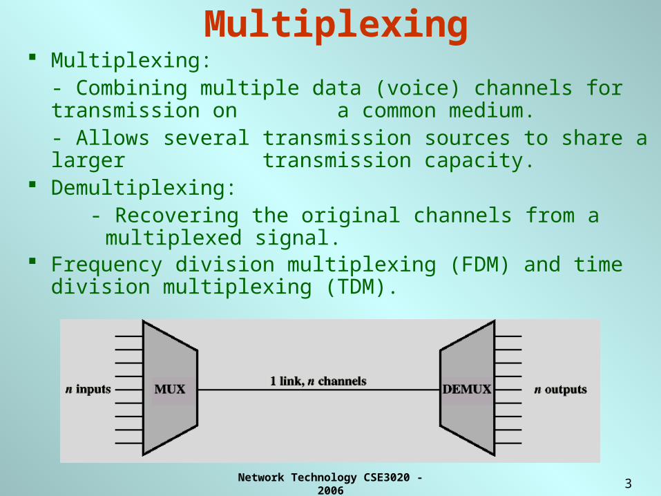
Multiplexing Multiplexing:
- Combining multiple data (voice) channels for transmission on a common medium.
- Allows several transmission sources to share a larger transmission capacity.
Demultiplexing: - Recovering the original channels from a multiplexed signal.
Frequency division multiplexing (FDM) and time division multiplexing (TDM).
Network Technology CSE3020 - 2006
4
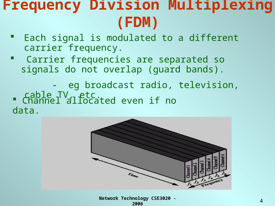
Frequency Division Multiplexing (FDM)
Each signal is modulated to a different carrier frequency.
Carrier frequencies are separated so signals do not overlap (guard bands).
- eg broadcast radio, television, cable TV, etc.
Channel allocated even if no data.
Network Technology CSE3020 - 2006
5
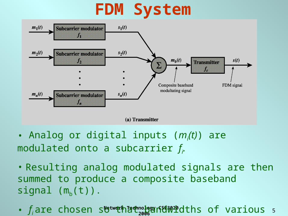
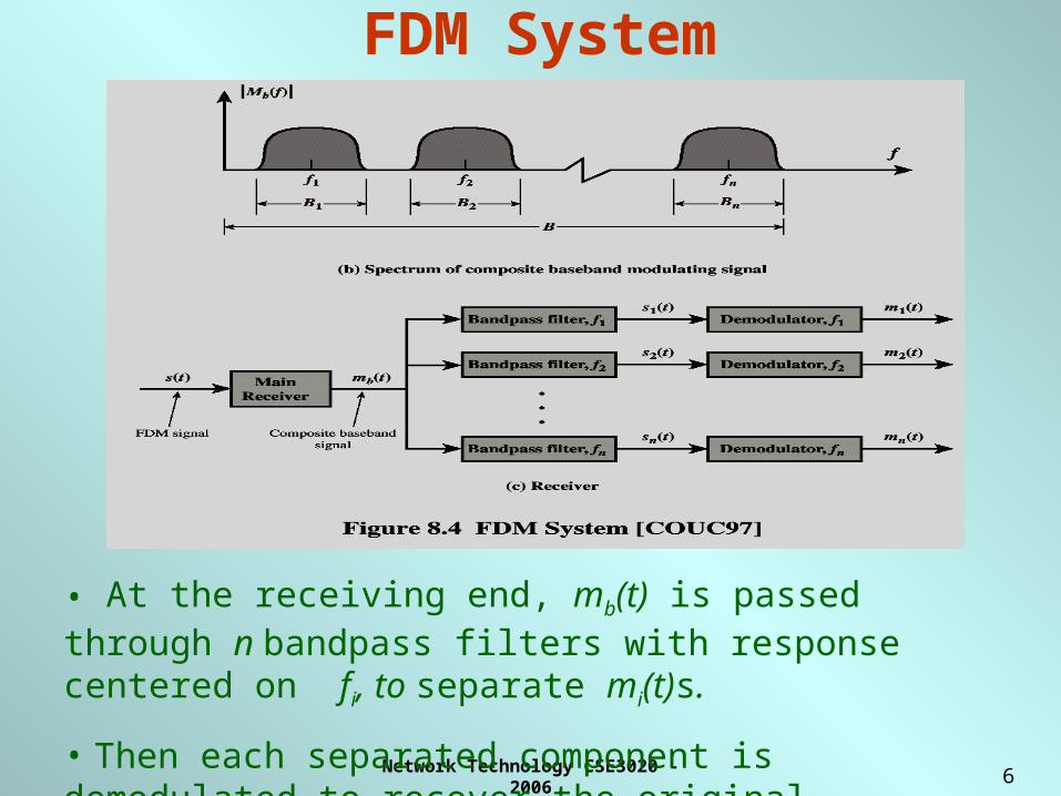
FDM System
• Analog or digital inputs (mi(t)) are modulated onto a subcarrier fi.
• Resulting analog modulated signals are then summed to produce a composite baseband signal (mb(t)).
• fi are chosen so that bandwidths of various signals do not significantly overlap.
Network Technology CSE3020 - 2006
6
FDM System
• At the receiving end, mb(t) is passed through n bandpass filters with response centered on fi, to separate mi(t)s.
• Then each separated component is demodulated to recover the original analog/digital data.
Network Technology CSE3020 - 2006
7
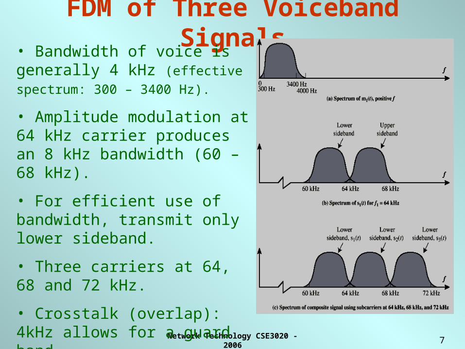
FDM of Three Voiceband Signals
• Bandwidth of voice is generally 4 kHz (effective spectrum: 300 – 3400 Hz).
• Amplitude modulation at 64 kHz carrier produces an 8 kHz bandwidth (60 – 68 kHz).
• For efficient use of bandwidth, transmit only lower sideband.
• Three carriers at 64, 68 and 72 kHz.
• Crosstalk (overlap): 4kHz allows for a guard band.
• Intermodulation noise: one channel could produce frequency components in other channels.
Network Technology CSE3020 - 2006
8
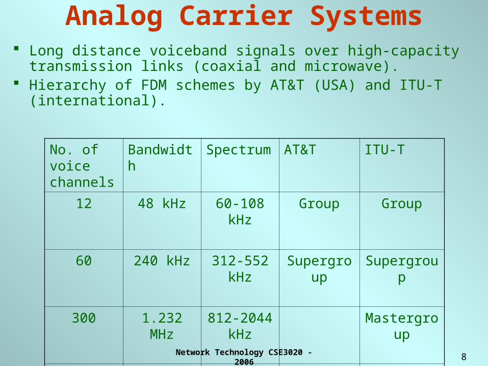
Analog Carrier Systems Long distance voiceband signals over high-capacity transmission
links (coaxial and microwave). Hierarchy of FDM schemes by AT&T (USA) and ITU-T
(international).
No. of voice channels
Bandwidth Spectrum AT&T ITU-T
12 48 kHz 60-108 kHz Group Group
60 240 kHz 312-552 kHz
Supergroup Supergroup
300 1.232 MHz 812-2044 kHz
Mastergroup
600 2.52 MHz 564-3084 kHz
Mastergroup
Network Technology CSE3020 - 2006
9
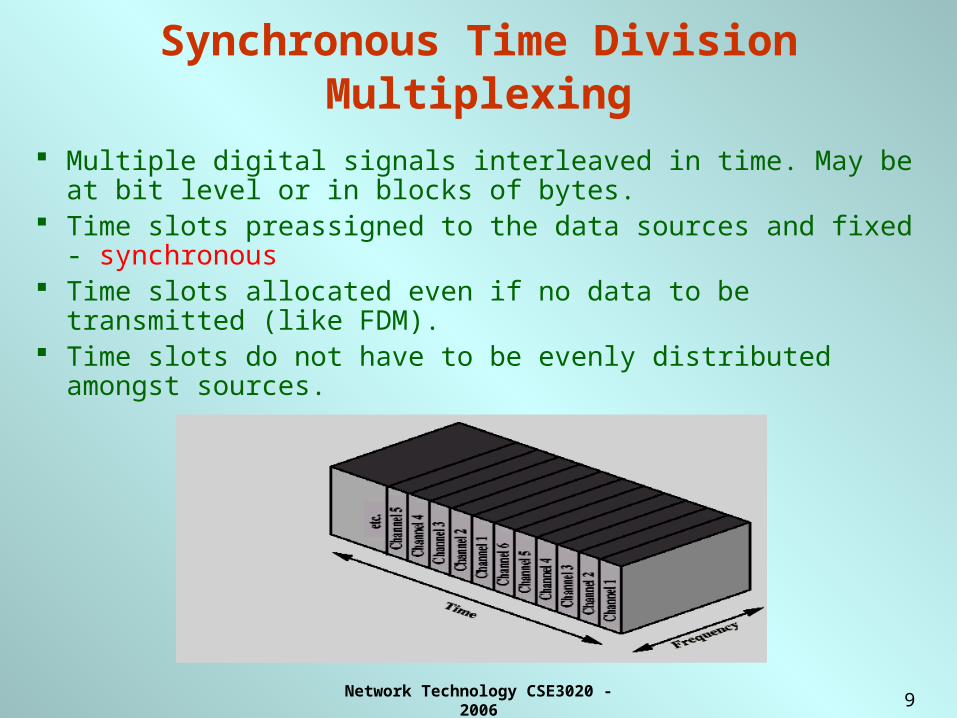
Synchronous Time Division Multiplexing
Multiple digital signals interleaved in time. May be at bit level or in blocks of bytes.
Time slots preassigned to the data sources and fixed - synchronous
Time slots allocated even if no data to be transmitted (like FDM). Time slots do not have to be evenly distributed amongst sources.
Network Technology CSE3020 - 2006
10
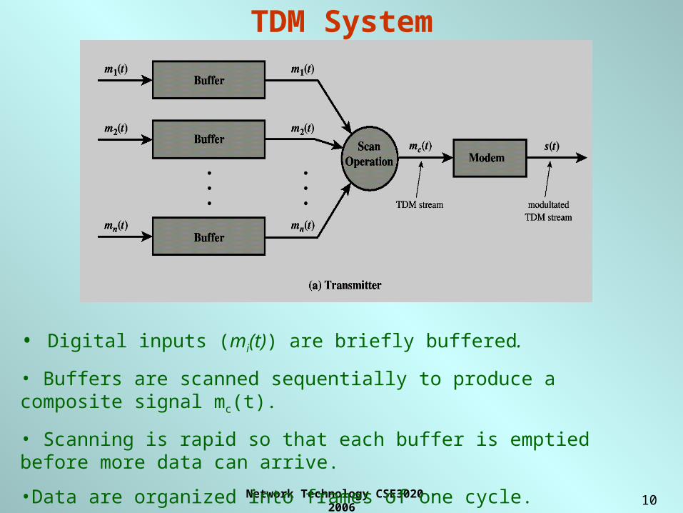
TDM System
• Digital inputs (mi(t)) are briefly buffered.
• Buffers are scanned sequentially to produce a composite signal mc(t).
• Scanning is rapid so that each buffer is emptied before more data can arrive.
•Data are organized into frames of one cycle.
Network Technology CSE3020 - 2006
11
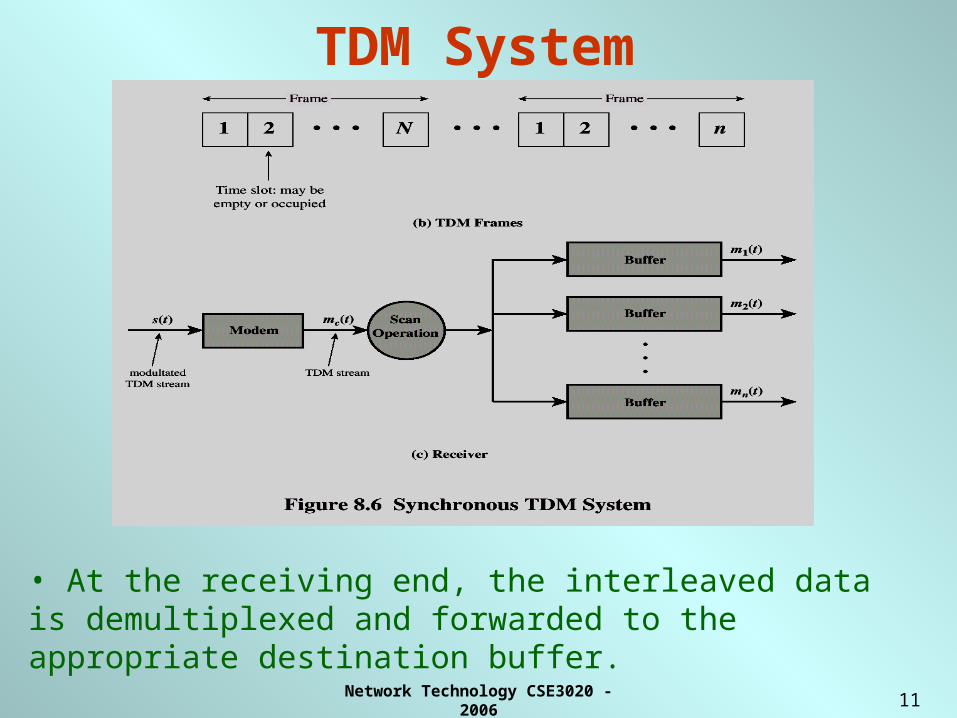
TDM System
• At the receiving end, the interleaved data is demultiplexed and forwarded to the appropriate destination buffer.
Network Technology CSE3020 - 2006
12
TDM Link Control No headers and trailers Data link control protocols not needed at this level
Flow control:
– not needed, data rate of multiplexed line is fixed
– if one channel receiver cannot receive data, the others will carry on.
– the corresponding source must cease transmission. This leaves empty slots for the corresponding channel.
Network Technology CSE3020 - 2006
13
TDM Link Control• Error control:
– if errors occur on one channel, the entire TDM frame is not retransmitted .
• Flow and Error Control can be provided on a per channel basis by using a data link protocol such as HDLC
• The multiplexing operation is transparent to the attached stations, to each it appears they have a dedicated link
Network Technology CSE3020 - 2006
14
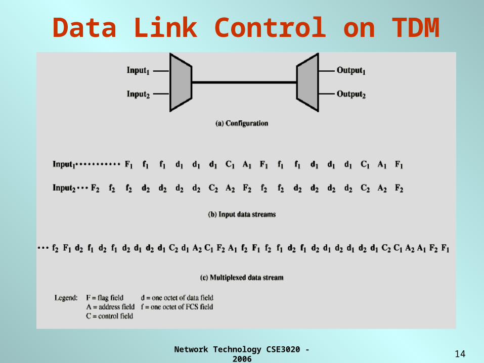
Data Link Control on TDM
Network Technology CSE3020 - 2006
15
Framing Must provide Frame synchronization mechanism.
Most common mechanism: Added digit framing.
– One control bit added to each TDM frame.
- Looks like another channel - “control channel”.
– Identifiable bit pattern used on control channel.
- e.g. alternating 01010101…unlikely on a data channel.
– Can compare incoming bit patterns on each channel with sync pattern.
– Once synchronized, the receiver monitors the control channel.
Network Technology CSE3020 - 2006
16
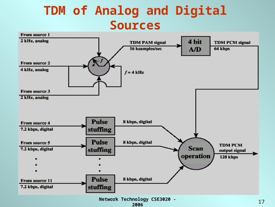
Pulse Stuffing Problem:
• Synchronizing the various data sources.• Separate clocks in different sources drifting.• Different data rates from different sources.
Solution: Pulse Stuffing.
• Outgoing data rate (excluding framing bits) higher than sum of incoming rates.
• Extra capacity is used to stuff extra dummy bits or pulses into each incoming signal until it matches local clock.
• Stuffed pulses inserted at fixed locations in frame and removed at demultiplexer.
Network Technology CSE3020 - 2006
17
TDM of Analog and Digital Sources
Network Technology CSE3020 - 2006
18
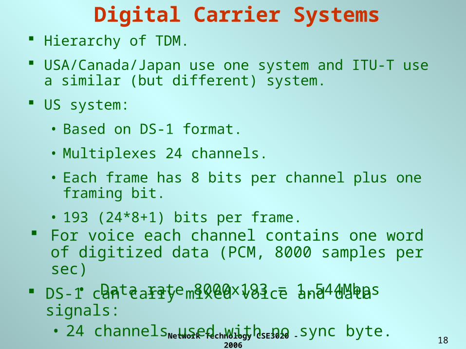
Digital Carrier Systems Hierarchy of TDM.
USA/Canada/Japan use one system and ITU-T use a similar (but different) system.
US system:
• Based on DS-1 format.
• Multiplexes 24 channels.
• Each frame has 8 bits per channel plus one framing bit.
• 193 (24*8+1) bits per frame. For voice each channel contains one word of digitized data
(PCM, 8000 samples per sec)• Data rate 8000x193 = 1.544Mbps
DS-1 can carry mixed voice and data signals:• 24 channels used with no sync byte.
Network Technology CSE3020 - 2006
19
Synchronous Optical Network (SONET)/ Synchronous Digital
Hierarchy (SDH) SONET is an optical transmission interface proposed by BellCore
and standardized by ANSI. SDH is defined by ITU-T for the use of high-speed transmission
capability of optical fiber. SONET and SDH are compatible. Signal Hierarchy:
– The lowest level is Synchronous Transport Signal level 1 (STS-1) or Optical Carrier level 1 (OC-1) and carries 51.84Mbps.
– STS-1 carries DS-3 or group of lower rate signals (DS1, DS1C, DS2) plus ITU-T rates (e.g. 2.048Mbps).
– Multiple STS-1 combined into STS-N signal– ITU-T lowest rate is 155.52Mbps (STM-1) and correspond to
STS-3.
Network Technology CSE3020 - 2006
20
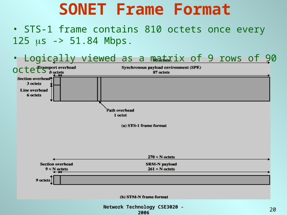
SONET Frame Format• STS-1 frame contains 810 octets once every 125 s -> 51.84 Mbps.
• Logically viewed as a matrix of 9 rows of 90 octets.
Network Technology CSE3020 - 2006
21
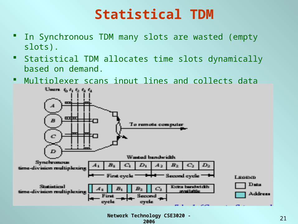
Statistical TDM
In Synchronous TDM many slots are wasted (empty slots). Statistical TDM allocates time slots dynamically based on demand. Multiplexer scans input lines and collects data until frame full Data rate on line lower than aggregate rates of input lines.
Network Technology CSE3020 - 2006
22
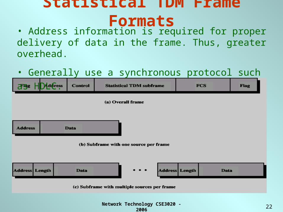
Statistical TDM Frame Formats
• Address information is required for proper delivery of data in the frame. Thus, greater overhead.
• Generally use a synchronous protocol such as HDLC.
Network Technology CSE3020 - 2006
23
Performance
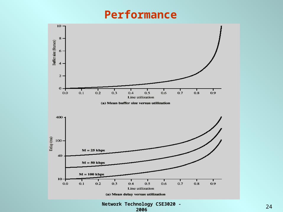
Output data rate less than aggregate input rates.
Anticipate the average rate is less than the multiplexed line capacity.
May cause problems during peak periods, input exceeds capacity
Use buffer to hold excess input.
Minimum buffer size to reduce delay.
As utilization rises, he buffer requirements and delay also increases.
Network Technology CSE3020 - 2006
24
Performance
Network Technology CSE3020 - 2006
25
Required Reading
• W. Stallings, “Data and Computer Communications” Prentice-Hall
Ch 8, Sections 8.1, 8.2, 8.3 7E/6E
Network Technology CSE3020 - 2006
26
Switching Networks
Network Technology CSE3020 - 2006
27
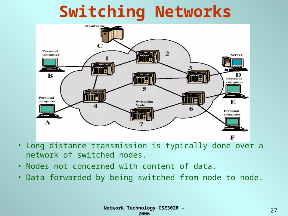
Switching Networks
• Long distance transmission is typically done over a network of switched nodes.
• Nodes not concerned with content of data.
• Data forwarded by being switched from node to node.
Network Technology CSE3020 - 2006
28
Switching Nodes
• Nodes may connect to other nodes only, or to stations and other nodes.
• Node to node links usually multiplexed.
• Network is usually partially connected.
– Some redundant connections are desirable for reliability.
• Two different switching technologies:
– Circuit switching.
– Packet switching.
Network Technology CSE3020 - 2006
29
Circuit Switching
• Circuit switching designed for voice:- Resources dedicated to a particular call.- Much of the time a connection is idle.- Data rate is fixed. Both ends must operate at the same rate.
• Dedicated communication path between two stations.• Three phases:
- Circuit establishment.- Data transfer.- Circuit disconnect.
• Must have switching capacity and channel capacity to establish connection.
• Must have intelligence to work out path to destination.
Network Technology CSE3020 - 2006
30
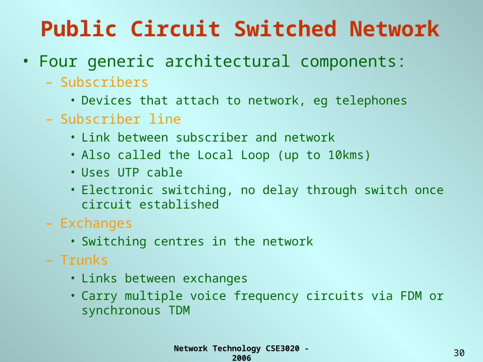
Public Circuit Switched Network• Four generic architectural components:
– Subscribers• Devices that attach to network, eg telephones
– Subscriber line• Link between subscriber and network• Also called the Local Loop (up to 10kms)• Uses UTP cable• Electronic switching, no delay through switch once circuit
established
– Exchanges• Switching centres in the network
– Trunks• Links between exchanges• Carry multiple voice frequency circuits via FDM or
synchronous TDM

Network Technology CSE3020 - 2006
31
Public Circuit Switched Network
Network Technology CSE3020 - 2006
32
Circuit Switching Concepts
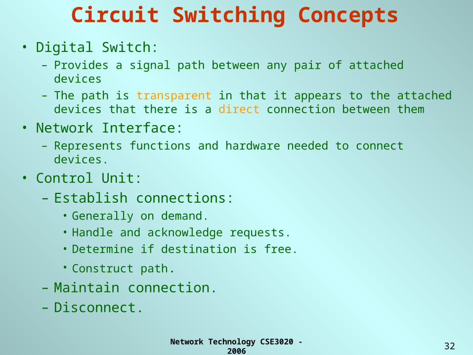
• Digital Switch:– Provides a signal path between any pair of attached devices
– The path is transparent in that it appears to the attached devices that there is a direct connection between them
• Network Interface:– Represents functions and hardware needed to connect devices.
• Control Unit:
– Establish connections:• Generally on demand.
• Handle and acknowledge requests.
• Determine if destination is free.
• Construct path.
– Maintain connection.
– Disconnect.
Network Technology CSE3020 - 2006
33
Circuit Switching Concepts
• Control signals are the means by which the network is managed and by which calls are established, maintained and terminated.
• Control Signaling Functions:– Call establishment & Termination.– Billing information.– Control of specialist equipment.– Two types of signaling: Common channel signaling &
Inchannel signaling.– Common channel signaling is more flexible and powerful.– Most widely used scheme is Signaling System Number 7
(SS7).
Network Technology CSE3020 - 2006
34
Circuit Switching
• Channel capacity dedicated for duration of connection.
• If no data, capacity wasted.
• Set up (connection) takes time.
• Once connected, transfer is transparent.
• Developed for voice traffic (phone).
Network Technology CSE3020 - 2006
35
Blocking
• Blocking:– If the network is unable to connect stations because all paths are in use,
the call is blocked
– Engaged tone on voice call
• Non-blocking:– Permits all stations to connect (in pairs) at once, to transmit data
– Possible in packet switched networks.
Network Technology CSE3020 - 2006
36
Packet Switching• Data transmitted in small packets.
– Typically 1000 octets.
– Longer messages split into series of packets.
– Each packet contains a portion of user data plus some control information: Routing (addressing).
• Packets are received, stored briefly (buffered) and passed on to the next node.
– Store and forward.
• Transmission time depends on the packet size.
– Optimum packet size to reduce delay & overhead.

Network Technology CSE3020 - 2006
37
Packet Switching
• Station breaks long messages into packets.• Packets sent one at a time to the network.• Packets handled in two ways.
– Datagram.– Virtual circuit.
Network Technology CSE3020 - 2006
38
Packet Switching: Advantages
• Line efficiency:
– Single node to node link can be shared by many packets over time.
– Packets queued and transmitted as fast as possible.
• Data rate conversion:
– Each station connects to the local node at its own speed.
– Nodes buffer data if required to equalize rates.
• Packets are accepted even when network is busy.
– Delivery may slow down.
• Priorities can be used.
Network Technology CSE3020 - 2006
39
Packet Switching: Datagram
• Each packet treated independently.• Packets can take any practical route.• Packets may arrive out of order.• Packets may go missing.• Receiver to re-order packets and recover from missing packets.• No call setup phase: Better if few packets.• More flexible: Routing can be used to avoid congested paths of
the network.
Network Technology CSE3020 - 2006
40
Packet Switching: Virtual Circuit
• Preplanned route established before any packets sent.
• Call request and call accept packets establish connection (handshake).
• Each packet contains a virtual circuit identifier instead of destination address.
• No routing decisions required for each packet
• Network can provide sequencing and error control.
• Clear request to drop circuit.
• Loss of a node losses all circuits through that node
Network Technology CSE3020 - 2006
41
Circuit & Packet Switching• Performance
– Propagation delay
– Transmission time.
– Node delay.
.
Network Technology CSE3020 - 2006
42
Required Reading
• W. Stallings, Data and Computer Communications Prentice-Hall.
Ch 9/10, Sections 9.1-3, 10.1 6E
Ch 10, Sections 10.1-6 7E