Embed Size (px)
Citation preview

Journal of Mechanical Science and Technology 26 (4) (2012) 1179~1196
www.springerlink.com/content/1738-494x DOI 10.1007/s12206-012-0212-2
Neuro-fuzzy control strategy for an offshore steel jacket platform subjected to
wave-induced forces using magnetorheological dampers† Atabak Sarrafan*, Seiyed Hamid Zareh, Amir Ali Akbar Khayyat and Abolghassem Zabihollah
School of Science and Engineering, Sharif University of Technology, Iran
(Manuscript Received April 26, 2011; Revised October 31, 2011; Accepted November 24, 2011)
----------------------------------------------------------------------------------------------------------------------------------------------------------------------------------------------------------------------------------------------------------------------------------------------
Abstract Magnetorheological (MR) damper is a prominent semi-active control device to vibrate mitigation of structures. Due to the inherent
non-linear nature of MR damper, an intelligent non-linear neuro-fuzzy control strategy is designed to control wave-induced vibration of an offshore steel jacket platform equipped with MR dampers. In the proposed control system, a dynamic-feedback neural network is adapted to model non-linear dynamic system, and the fuzzy logic controller is used to determine the control forces of MR dampers. By use of two feedforward neural networks required voltages and actual MR damper forces are obtained, in which the first neural network and the second one acts as the inverse dynamics model, and the forward dynamics model of the MR dampers, respectively. The most important characteristic of the proposed intelligent control strategy is its inherent robustness and its ability to handle the non-linear behav-ior of the system. Besides, no mathematical model needed to calculate forces produced by MR dampers. According to linearized Morison equation, wave-induced forces are determined. The performance of the proposed neuro-fuzzy control system is compared with that of a traditional semi-active control strategy, i.e., clipped optimal control system with LQG-target controller, through computer simulations, while the uncontrolled system response is used as the baseline. It is demonstrated that the design of proposed control system framework is more effective than that of the clipped optimal control scheme with LQG-target controller to reduce the vibration of offshore structure. Furthermore, the control strategy is very important for semi-active control.
Keywords: Clipped optimal control system; Magnetorhelogical damper; Neuro-fuzzy control strategy; Semi-active control; Wave-induced vibration ---------------------------------------------------------------------------------------------------------------------------------------------------------------------------------------------------------------------------------------------------------------------------------------------- 1. Introduction
In modern world, oil crisis has become a bottle-neck of economy. Therefore the offshore structures, especially the oil and gas production platforms, play a more and more important role. The environment surrounding offshore platforms is harsh and complicated. A schematic of sample offshore steel jacket platform under environmental loading is illustrated in Fig. 1. As well as erosion from sea water, they may have to endure strong dynamic forces caused by wind, sea wave, sea current, sea ice and even earthquake. Therefore, the structural safety and durability of offshore platforms have raised great concerns of oil industry. To prevent fatigue damage, to ensure safety and production efficiency and to make people on the platform comfortable, displacement and acceleration of the platforms should be limited. Many control schemes have been studied to suppress the vibration of offshore structures [1-9]. Consider-ing issues of control system reliability and power supply, pas-
sive [5-8] and semi-active control [9] are more appealing than active one [1-4].
Recently, semi-active control systems have attracted a great deal of attention in civil engineering field, because they offer the adaptability of active control devices while without requir-ing large power sources. The MR damper is a new kind of semi-active control device which utilizes the essential charac-
*Corresponding author. Tel.: +989168048974, Fax.: +987224223895 E-mail address: [email protected]
† Recommended by Associate Editor Junzhi Yu © KSME & Springer 2012
Fig. 1. Environmental loading on offshore steel jacket platform.

1180 A. Sarrafan et al. / Journal of Mechanical Science and Technology 26 (4) (2012) 1179~1196
teristic of MR fluids being their ability to reversibly change from free-flowing, linear viscous liquids to semi-solids having controllable yield strength in milliseconds when exposed to magnetic field. At the same time it has merits of simple con-struction, cheap cost and excellent control effect thereby gain-ing more attention. When structures deform due to vibration, MR dampers will adjust their characteristic parameters in accordance with given control laws and will absorb vibration energy. From this point of view, structural vibration control using MR dampers is one of the most promising fields in civil engineering, and a wide range of theoretical and experimental studies have been performed to assess the efficacy of MR dampers [10-15]. Recent tests of a 20-ton MR damper at the University of Notre Dame have demonstrated that these de-vices can provide forces of the magnitude required for full-scale structural control applications [16].
Because MR dampers are highly non-linear devices, devel-oping control algorithms to fully take advantage of their char-acteristics has been challenging. Several control strategies have been proposed to use with these devices [16, 18-43], and as shown in Ref. [17], they can be categorized as model-based control, that is, algorithms that require an accurate mathemati-cal model of the system and intelligent control. The perform-ance of some of the control systems proposed has been com-pared through simulations [12, 20, 30].
Although model-based control strategies have been success-ful to reduce structural vibrations, all models developed are based on assumptions and uncertainties which can greatly affect their accuracy, and therefore influence controller’s performance. One must, therefore, make sure that these model-based control-lers are robust enough to control the real life structures. The non-linear nature and complexity of systems have also lead to the creation of sophisticated models which are often computa-tionally intensive, and therefore difficult and sometimes even impractical to use in the development of control strategies. Intel-ligent technology-based control has therefore been suggested as an alternative to strategies that rely on system model. Three main categories of intelligent control algorithms have been pro-posed to use with the MR dampers: neural network-based con-trol, fuzzy logic-based control and neuro-fuzzy based control.
Neural network and fuzzy controller techniques can offer a simple and robust framework for specification of non-linear control laws that can accommodate uncertainty and impreci-sion. In recent years, neural network and fuzzy control tech-niques are used widely for the semi-active vibration control in civil engineering. In the category of neuro-control, Ni et al. [34] proposed a neuron-control method for semi-active vibra-tion control of stay cables using MR dampers. The analysis results showed that the proposed control strategies could ef-fectively implement semi-active vibration control of stay ca-bles with the use of MR dampers. Shiraishi et al. [35] pro-posed an adaptive neural network to control a three-story structural model equipped with a prototype damper they de-signed and constructed. Numerical simulations and experi-ments, which showed good agreement, verified the perform-
ance of their proposed control strategy. Based on neural net-works, Dalei and Jianqiang [36] employed an indirect adap-tive control strategy to control MR dampers on base isolated structures. They used back propagation algorithm with mo-mentum term to train the weights of two used neural networks. Through numerical simulation they showed that the proposed strategy is more effective than the use of a neural network controller without quadratic momentum term. Xu et al. [37] proposed the use of neural networks to control MR dampers. Numerical simulation results on a three-story reinforced con-crete structure model showed that this control method is more effective than the traditional elastoplastic time-history analysis method. In the category of fuzzy-control, Wang [38] described an adaptive fuzzy control strategy that Zhou et al. [39] suc-cessfully applied for control of linear and non-linear structures. They showed that the adaptive feature of a fuzzy controller has multiple advantages in controlling a building that has an MR damper system. Yan and Zhou [40] presented a design strategy based on genetic algorithm (GA) for semi-active fuzzy control of structures that have MR dampers installed to prevent damage from severe dynamic loads such as earth-quakes. They employed GA as an adaptive method for design of the fuzzy controller, which is known as a genetic adaptive fuzzy (GAF) controller. They showed the effectiveness and efficiency of their proposed intelligent control strategy using numerical simulations for single and multiple damper cases. Ok et al. [41] proposed a semi-active fuzzy control technique to enhance the seismic performance of cable-stayed bridges using MR dampers. They designed the fuzzy logic controller to directly determine the input voltage of an MR damper from the response of the MR damper. They proved that their pro-posed semi-active fuzzy control technique can effectively mitigate the seismic response of cable-stayed bridges and successfully enhance the robust performance of the MR dam-per system. In the category of neuro-fuzzy control, Xu and Guo [42] proposed neuro-fuzzy control strategy, in which the neural-network technique is adopted to solve time-delay prob-lem and the fuzzy controller is used to determine the control current of MR dampers quickly and accurately. Through a numerical example, they proved that the control effect of the neuro-fuzzy control strategy is better than that of the bi-state control strategy. Schurter and Roschke [43] presented a neuro-fuzzy technique to reduce the environmentally-induced vibra-tion of two types of MR-building models. They developed a correlation between accelerations of the building (fuzzy con-troller input) and voltage applied to the MR damper (fuzzy controller output). The developed correlation formed the basis of their proposed intelligent neuro-fuzzy control strategy. Ac-cording to numerical simulation, they showed that MR damp-ers are less effective control mechanisms than passive damp-ers with respect to a single degree of freedom (DOF) building model. Moreover, MR dampers are superior when used with multiple DOF structures to reduce the lateral acceleration.
The previous studies made full use of the advantages of the neural network and the fuzzy logic, and solved the different

A. Sarrafan et al. / Journal of Mechanical Science and Technology 26 (4) (2012) 1179~1196 1181
problems which lay in the civil engineering structures. Few researches involved combination of the two techniques to solve the inherent non-linear nature problem of the MR dam-per to generate ideal damping force for vibration control of offshore structures under wave-induced forces. In current research, the control objective is to reduce both the displace-ment response that determines the structural safety and the acceleration response that reflects the comfort level of occu-pants. In this paper, four MR dampers are added in an offshore steel jacket platform [44]. For the intelligent structure under wave loading, a dynamic-feedback neural network is adapted to model non-linear dynamic system and the fuzzy logic con-troller is used to determine the control forces of MR dampers. Required voltages and actual MR damper forces are obtained by use of two feedforward neural networks, in which the first neural network and second one act as the inverse dynamics model and the forward dynamics model of the MR dampers, respectively. In order to verify the effectiveness of the pro-posed neuro-fuzzy control strategy, the uncontrolled structure and the semi-actively controlled using clipped optimal control algorithm structure are compared with the neuro-fuzzy con-trolled structure. Through a numerical example, it can be con-cluded that the control strategy is very important for semi-active control, and the control effect of the neuro-fuzzy con-trol strategy is better than that of the clipped optimal control strategy with LQG-target controller.
2. Modeling of an offshore steel jacket platform
In this paper, finite element method (FEM) is utilized to model an offshore steel jacket platform. The FEM provides a practical and less expensive way to study the dynamic response of offshore structures under environmental loadings. General beam element or simply frame element is used in this research. The frame element is seen to posses the properties of both truss and beam elements. In fact, the frame structures can be found in most of our real world structural problems, for there are not many structures that deform and carry loadings purely in neither axial directions nor purely in transverse directions.
In a planar frame element, there are 3 DOFs at each node in local coordinate system. They are the axial deformation in the x direction, u, deflection in y direction, v, and the rotation in the x–y plane and with respect to the z-axis, θz. Therefore, each element with two nodes has a total of 6 DOFs. Displacement and rotation components at node i are ui, vi and θzi, i = 1, 2. DOFs of a frame element are shown in Fig. 2.
The forces and displacements in local coordinate system are related by use of Eq. (1) [45].
1 1
1 1
11
2 2
2 2
2 2
x
y
ze
x
y
z
f uf vM
kf uf vM
θ
θ
⎧ ⎫ ⎧ ⎫⎪ ⎪ ⎪ ⎪⎪ ⎪ ⎪ ⎪⎪ ⎪ ⎪ ⎪⎪ ⎪ ⎪ ⎪⎨ ⎬ ⎨ ⎬⎪ ⎪ ⎪ ⎪⎪ ⎪ ⎪ ⎪⎪ ⎪ ⎪ ⎪⎪ ⎪ ⎪ ⎪⎩ ⎭ ⎩ ⎭
=
(1)
where
3 2 3 2
2 2
e
3 2 3 2
2 2
0 0 0 02 2
3 3 3 30 02 2 2 2
3 2 30 02 2 .0 0 0 0
2 23 3 3 30 02 2 2 2
3 3 20 02 2
z z z z
z z z z
z z z z
z z z z
AE AEa a
EI EI EI EIa a a a
EI EI EI EIa a a ak
AE AEa a
EI EI EI EIa a a a
EI EI EI EIa a a a
⎡ ⎤⎢ ⎥⎢ ⎥⎢ ⎥⎢ ⎥⎢ ⎥⎢ ⎥⎢ ⎥⎢ ⎥⎢ ⎥⎢ ⎥⎢ ⎥⎢ ⎥⎢ ⎥⎢ ⎥⎢ ⎥⎣ ⎦
−
−
−=
−
− − −
−
(2)
In Eq. (1), fxi, fyi, are forces applied to node i in x and y di-
rection, respectively, Mi are moment applied to node i, i = 1, 2, ke is a 6× 6 stiffness matrix of each element in local coordi-nate system. In stiffness matrix ke, A is cross sectional area of the element, le is the element length = (2a), Iz is the moment of inertia of the cross section of the beam with respect to z-axis, E is Young’s modulus of element. The 6× 6 mass matrix of each element me in local coordinate system is stated in Eq. (3).
2 2
e
2 2
70 0 0 35 0 00 78 22 0 27 130 22 8 0 13 6
105 35 0 0 70 0 00 27 13 0 78 220 13 6 0 22 8
a aa a a aAam
a aa a a a
ρ
⎡ ⎤⎢ ⎥⎢ ⎥⎢ ⎥⎢ ⎥⎢ ⎥⎢ ⎥⎢ ⎥⎢ ⎥⎣ ⎦
−−
=
−− − −
(3)
where ρ is mass density of the element. Transformation matrix T, which relates matrices in local coordinate system to global ones, is introduced in Eq. (4).
cos sin 0 0 0 0sin cos 0 0 0 00 0 1 0 0 00 0 0 cos sin 00 0 0 sin cos 00 0 0 0 0 1
T
α αα α
α αα α
⎡ ⎤⎢ ⎥⎢ ⎥⎢ ⎥⎢ ⎥⎢ ⎥⎢ ⎥⎢ ⎥⎢ ⎥⎣ ⎦
−
=
− (4)
Fig. 2. DOFs of a planar frame element [45].

1182 A. Sarrafan et al. / Journal of Mechanical Science and Technology 26 (4) (2012) 1179~1196
where α is the angle between the x-axis of local and X-axis of global coordinating systems.
Eqs. (5) and (6) are used to transform the stiffness and mass matrices of each frame element into global coordinate system. In the same manner, the force vector applied to the frame ele-ment is transformed into the global coordinate system by Eq. (7).
T
e ekK T T= (5) T
eeM T m T= (6) T
e eF T f= (7) The structural model of a fixed offshore steel jacket plat-
form is illustrated in Fig. 3. The geometric properties of offshore steel jacket platform
are in Table 1 [44].
3. Modeling of wave-induced forces
Offshore structures are exposed to non-linear hydrodynamic forces. The non-linearity of these forces arises from their de-pendence on the flexibility of the structure which induces a self-excited load term [46]. The fluid forces acting on a cylin-der, considering the relative motion of body in the fluid is modeled using the well-known Morison Eq. [47]. For an ele-ment of a cylinder element, this equation is [48]
1 ( )2w n n n n nM Dwdf dVC q C dA q x q xρ ρ= + − − (8)
where dfw is wave force per unit length of the member, CD and CM are drag and inertia coefficients, respectively, dV and dA are displaced volume of the member and projected area nor-mal to the member axis, ρw is the mass density of water, qn and qn infer to the time dependent velocity and acceleration of the fluid normal to member axis at joint n, respectively, xn is the absolute velocity of joint n, and (qn – xn) is the relative water velocity at joint n. Velocity and acceleration of water particle
can be derived according to relevant wave theories. Stokes second order wave theory is utilized to calculate the horizontal and vertical water particle velocity and acceleration [49, 50]
cosh ( ) cos( )sinh
H k y du kx tT kdπ ω+
= − (9) 2 2
4
3 cosh ( ) cos[2( )]4 sinhH k y d kx tT kdπ ωλ
++ −
2
2
2 cosh ( ) sin( )sinh
H k y du kx tT kdπ ω+
= − (10)
2 3
2 4
3 cosh 2 ( ) sin[2( )]sinh
H k y d kx tT kd
π ωλ
++ −
sinh ( ) sin( )sinh
H k y dv kx tT kdπ ω+
= − (11)
22
4
3 sinh 2 ( ) sin[2( )]4 sinhH k y d kx tT kdπ ωλ
++ −
2
2
2 sinh ( ) cos( )sinh
H k y dv kx tT kdπ ω+
= − − (12)
2 3
2 4
3 sinh 2 ( ) cos[2( )]sinh
H k y d kx tT kd
π ωλ
+− −
where u and u are horizontal water particle velocity and accel-eration, respectively, v and v are vertical water particle veloc-ity and acceleration, respectively, x and y are the location of
Fig. 3. A fixed offshore steel jacket platform [44].
Table 1. Geometric properties of cylindrical steel members of offshore platform.
Element No.Outside diameter
(m)
Length (m)
Thickness(mm) α (°)
1 0.457 8.1415 10 0
2 0.457 8.1415 10 180
3 0.273 8.20 7 90
4 0.273 11.555 7 130.94
5 0.273 11.555 7 45.205
6 0.273 10.019 7 45.205
7 0.559 15.2897 11 93.86
8 0.559 15.2897 11 86.145
9 0.356 14.137 8 180
10 0.457 18.704 10 134.87
11 0.559 13.256 11 93.86
12 0.559 13.256 11 86.145
13 0.324 12.256 8 180
14 0.457 16.216 10 45.13
15 0.406 11.492 9 93.86
16 0.406 11.492 9 86.145
17 0.324 10.625 8 180
18 0.381 14.058 8 134.87
19 0.406 9.963 9 93.86
20 0.406 9.963 9 86.145
21 0.381 9.212 8 180

A. Sarrafan et al. / Journal of Mechanical Science and Technology 26 (4) (2012) 1179~1196 1183
each joint with respect to a fixed reference, H is wave height, T is wave period, k is the wave number = (2π/λ), λ is the wave length, ω is the wave frequency, d is the water depth, and t is the time. Wave symbols are shown in Fig. 4.
It should be noted that there are various sources of inaccu-racies in Eq. (8), e.g. from the use of constant values for CD and CM, which are, in fact, frequency and depth dependent. As can be observed, Eq. (8) considers the non-linear self-excited and drag forces. Using a stochastic linearization technique the Morison equation is thus approximated as [49]:
1 8 ( )2w n vr n nM Dwdf dVC q C dA q xρ ρ σ
π= + − (13)
where σvr is the Root Mean Squares (RMS) values of the rela-tive velocity between water particles and the structure at each joint. The values at each step are obtained from the relative velocity up to the previous time step [51]. In this paper, Eq. (13) is utilized to simulate the wave hydrodynamic forces.
4. Motion equations for offshore structures with MR
dampers
4.1 Mathematical model of MR dampers
In recent years, smart structures have been adopted from many engineering fields because the performance of structural systems can be improved without either significantly increas-ing the structure mass or requiring high cost of control power. They may be called intelligent structures, adaptive structures, active structures and the related technologies adaptronics, structronics, etc. These terminologies refer to a smart structure which is an integration of actuators, sensors, control units, and signal processing units with a structural system. The materials that are usually used to implement the smart structure are: piezoelectrics, shape memory alloys, electrostrictive/magne- tostrictive materials, polymer gels, etc. [52].
Generally, an MR damper consists of a hydraulic cylinder, magnetic coils, and MR fluids that consist of micron-sized magnetically polarizable particles floating within oil-type fluids as shown in Fig. 5. The MR damper is operated as a passive damper; however, when a magnetic field is applied to the MR damper fluids, the MR fluids are changed into a semi-
active device in a few milliseconds. Its characteristics are summarized: (1) an MR damper is operated with low power sources, e.g., SD-1000 MR damper can generate a force up to 3000 N using a small battery with capacity less than 10 W; (2) it has high yield stress level, e.g., its maximum yield stress is beyond 80 kPa; (3) the performance is stable in broad tem-perature range, e.g., MR fluids operate at the temperature be-tween –40 and 150°C; (4) the response time is a few millisec-onds; (5) the performance is not sensitive to contamination during manufacturing of the MR damper. Moreover, the oper-ating point of the MR damper, which is a current-controlled device, can be changed by a permanent magnet [33].
Adequate modeling of the control device is essential for ac-curately predicting the behavior of the controlled system. A number of mechanical models for non-linear damper system have recently been proposed by several researchers [12, 53, 54]. In this paper, a simple mechanical model consist of a Bouc-Wen element in parallel with a viscous damper is used, as shown in Fig. 6. This model has been verified to predict accurately the behavior of a prototype shear-mode MR dam-per over a wide range of inputs in a set of experiments [20, 21], and is also expected to be appropriate to model a full-scale MR damper [23].
The equations governing the force f exerted by this model are as follows [41]:
0f c x zα= + (14)
1n nmz x z z x z A xγ β−= − − + (15)
Fig. 4. Wave symbols [49].
Fig. 5. Schematic of the prototype 20-ton large scale MR damper [33].
Fig. 6. Mechanical model of a shear mode type MR damper [41].

1184 A. Sarrafan et al. / Journal of Mechanical Science and Technology 26 (4) (2012) 1179~1196
where x is the displacement of the device, z is the evolutionary variable that accounts for the history dependence of the re-sponse. The parameters γ, β, n, and Am are adjusted to deter-mine the linearity in the unloading and the smoothness of the transition from the pre-yield region to the post-yield region. Device model parameters α and co are determined by the de-pendency on the control voltage uc, as follows:
( ) a b cu uα α α α= = + (16)
0 0 0 0( ) .ca bc c u c c u= = + (17) Therefore, the control voltage applied to the current driver
in the MR damper continuously modulates the damping force of the MR damper. Moreover, to account for a time-lag in the response of the device to the changes in the command input, the first-order filter dynamics are introduced into the system as follows:
( )cu uη υ= − −& (18)
where υ is command voltage applied to the control circuit, and η is the time constant of the first-order filter.
In order to obtain a dynamic model of an MR damper with a capacity of 1000 kN, the parameters of a shear-mode proto-type MR damper were identified from the test results obtained at Washington University, and scaled up so as to have the maximum capacity of 1000 kN with the maximum command voltage Vmax = 10 V [23]. These parameters are listed in Table 2 [41].
The hysteretic behavior of the MR damper model according to the input voltage is shown in Fig. 7.
Installation layout of MR dampers are illustrated in Fig. 8. The MR dampers are attached to the platform in diagonal fashion. The effectiveness of installation layout of MR damp-ers on offshore steel jacket platform has been verified in Ref. [44]. In what follows, a methodology which designs a control law for operation of an MR damper is addressed.
4.2 Motion equations of intelligent offshore structure
The jacket-type offshore structure is modeled using 12 nodes and 21 general beam elements. The dynamical differen-
tial equation of motion of semi-actively controlled 30-DOFs structural system subjected to external wave loads and control forces can be expressed as:
wd MRMx C x Kx Γf Λf+ + = +&& &
(19)
where M, Cd, and K are 30× 30 mass, damping, and stiffness matrices of structure, respectively, Γ is 30× 30 location matrix for hydrodynamic wave force vector fw, fw is 30× 1 wave force vector acting on nodes 3-12 of offshore structure, Λ is 30× 4 location matrix for forces produced by MR dampers fMR, fMR is 4× 1 vector for forces produced by MR dampers 1-4 through clipped optimal control algorithm, x, x and x are 30× 1 the acceleration, the velocity and the displacement vec-tors of the structure nodes relative to the ground, respectively.
Rayleigh's technique is used to estimate damping in the structure [48]. In this technique, it is assumed that the damp-ing matrix Cd is proportional to the mass matrix M and the stiffness matrix K, or:
dC αM βK= +
(20)
where α and β are related somehow to the critical damping of first two modes of vibration [48]. The values of α and β are
Table 2. Parameters of the MR damper model.
αa (N/cm) 1.0872× 10⁵
αb (N/cm.V) 4.9616× 10⁵
c0a (N.s/cm) 4.40
c0b (N.s/cm.V) 44.0
Am 1.2
n 1
β (1/cm) 3
γ (1/cm) 3
η (1/s) 50
Fig. 7. Hysteretic behavior of an MR damper [41].
Fig. 8. Installation layout of MR dampers on offshore platform [44].
A. Sarrafan et al. / Journal of Mechanical Science and Technology 26 (4) (2012) 1179~1196 1185
determined by Eqs. (21) and (22).
1 2
1 22 ωωα ζ
ω ω=
+ (21)
1 2
12 .β ζω ω
=+
(22)
Eq. (19) can be written in the state-space form as:
wMR
MR
z Az Bf Gfy Cz Df
⎧⎪⎨⎪⎩
= + += +
&
(23)
where:
x
zx⎡ ⎤⎢ ⎥⎣ ⎦
=&
(24)
3 3 3 12 12 12T
z zx U V θ . . . U V θ= [ ] (25)
30 30 30 301 1
0
d
IA
M K M C× ×− −
⎡ ⎤⎢ ⎥⎣ ⎦
=− −
(26)
30 301
0B
M Λ×−
⎡ ⎤⎢ ⎥⎣ ⎦
= (27)
30 41
0G
M Γ×
−⎡ ⎤⎢ ⎥⎣ ⎦
= (28)
0D = (29)
where z is the state space vector, y is output vector, A is state matrix, B is control input matrix, G is disturbance input matrix, C is output matrix, Ui and Vi are nodal displacements along X and Y-axis, respectively, and θzi is rotation about Z-axis, i = 3, ..., 12 .
It should be noted that to measure the feedback signal to the semi-active controller, four accelerometers and four displace-ment transducers are used. All of the accelerometers and dis-placement transducers are positioned on nodes 9-12 so as to measure the velocity and the displacement of these structural nodes along X-axis.
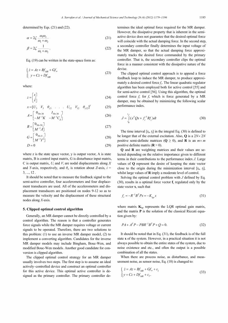
5. Clipped optimal control algorithm
Generally, an MR damper cannot be directly controlled by a control algorithm. The reason is that a controller generates force signals while the MR damper requires voltage or current signals to be operated. Therefore, there are two solutions to this problem: (1) to use an inverse MR damper model, (2) to implement a converting algorithm. Candidates for the inverse MR damper models may include Bingham, Bouc-Wen, and modified Bouc-Wen models. Another good candidate for con-version is clipped algorithm.
The clipped optimal control strategy for an MR damper usually involves two steps. The first step is to assume an ideal actively–controlled device and construct an optimal controller for this active device. This optimal active controller is de-signed as the primary controller. The primary controller de-
termines the ideal optimal force required for the MR damper. However, the dissipative property that is inherent in the semi-active device does not guarantee that the desired optimal force will coincide with the actual damping force. In the second step, a secondary controller finally determines the input voltage of the MR damper, so that the actual damping force approxi-mately tracks the desired force commanded by the primary controller. That is, the secondary controller clips the optimal force in a manner consistent with the dissipative nature of the devise.
The clipped optimal control approach is to append a force feedback loop to induce the MR damper, to produce approxi-mately a desired control force fc. The linear quadratic regulator algorithm has been employed both for active control [55] and for semi-active control [56]. Using this algorithm, the optimal control force fc for f, which is force generated by a MR damper, may be obtained by minimizing the following scalar performance index.
0
( )t f
T Tc c
tJ x Qx f Rf dt= +∫
(30)
The time interval [t0, tf] in the integral Eq. (30) is defined to
be longer that of the external excitation. Also, Q is a 2N× 2N positive semi-definite matrices (Q ≥ 0), and R is an m×m positive definite matrix (R > 0).
Q and R are weighting matrices and their values are se-lected depending on the relative importance given to different terms in their contributions to the performance index J. Large values of Q represent the desire of keeping the state vector close to the origin during the minimization interval [t0, tf], whilst large values of R imply a moderate level of control.
Solving the optimal control problem with J defined by Eq. (30), results in a optimal force vector fc regulated only by the state vector x, such that
1 T
c lqr xf R B Px K−= − = −
(31)
where matrix Klqr represents the LQR optimal gain matrix, and the matrix P is the solution of the classical Riccati equa-tion given by:
1 0.T TPA A P PBR B P Q−+ − + =
(32)
It should be noted that in Eq. (31), the feedback is of the full
state x of the system. However, in a practical situation it is not always possible to obtain the entire states of the system, due to noise existence and etc., and often the output is a possible combination of all the states.
When there are process noise, as disturbance, and meas-urement noise, as sensor noise, Eq. (18) is changed to:
.wMR 1
2MR
z Az Bf Gf εy Cz Df ε
⎧⎪⎨⎪⎩
= + + += + +
&
(33)

1186 A. Sarrafan et al. / Journal of Mechanical Science and Technology 26 (4) (2012) 1179~1196
The vectors ε1 and ε2 in Eq. (33) represent the process noise and the measurement noise, respectively. They are assumed as zero-mean Gaussian white noise, satisfying the following equation:
[ ] ( )T T
e e eE ε ε Q t Q Qδ τ1 1 = − = (34)
2 2[ ] ( )T Te e eE ε ε R t R Rδ τ= − = (35)
1 2[ ] 0TE ε ε = (36)
where Qe and Re are semi-definite and definite matrices, re-spectively, δ (t) is Dirac function.
When the full state is not available, the state x is replaced in Eq. (31) by an optimal state estimate x generated by a Kalman filter which is given by:
ˆ ˆ( )
ˆ ˆe eslqrx A BK K C x K y
y Cx
⎧⎪⎨⎪⎩
= − − +
=
&
(37)
where x is the state estimate to x, Kes is the gain of the Kalman filter is given by:
1.T
es eK P C R−=
(38) In which Pe is the stabilizing solution to the Riccati equa-
tion:
1 0T Te e e e e eP A A P P BR B P Q−+ − + =
(39)
so Eq. (31) is changed to:
1 ˆ ˆT
c lqrf R B Px K x.−= − = −
(40)
The force generated by the MR damper cannot be com-
manded; only the voltage v applied to the current driver for the MR damper can be directly changed. To induce the MR dam-per to generate approximately the desired optimal control force fc, the command signal v is selected as follows. When the MR damper is providing the desired optimal force (i.e., f = fc), the voltage applied to the damper should remain at the present level. If the magnitude of the force produced by the damper is smaller than the magnitude of the desired optimal force and the two forces have the same sign, the voltage ap-plied to the current driver [23] varies continuously in the range of [0-Vmax]. The secondary controller for continuously varying the command voltage can be stated as:
{ }( )i ci ci i iv V H f f f= −
(41)
max
max max
,,
i ci cici
ci
f for f fV V for f fμ⎧
⎨⎩
≤= > (42)
where fmax is maximum force produced by the damper (=1,000
kN), μ is coefficient relating the voltage to the force (=Vmax/fmax), H (.) is the Heaviside step function expressed as 0 or 1 [23], fi is the force produced by ith MR dampers which is applied to the structure. The block diagram of clipped optimal control algorithm is shown in Fig. 9.
6. Neuro-fuzzy control strategy
The idea of the proposed control strategy is to replace the traditional semi-active control strategy, clipped optimal con-trol algorithm, for MR dampers with an intelligent control scheme which is trained by collected time histories of offshore steel jacket platform response and voltage produced by clipped optimal control system during applying wave-induced forces. In the proposed control algorithm, there is no need to calculate MR damper forces by solving a set of differential equation which is computationally expensive. Moreover, the speed of execution of this algorithm is higher than the model-based controllers. Another important characteristic of this control scheme is its robustness which is especially desirable in structural control applications characterized by uncertainties.
In this research, vibration of offshore structure due to wave forces is controlled by use of clipped optimal control algo-rithm with LQR target controller at first. The data obtained by this algorithm is used to train different parts of proposed neu-ro-fuzzy control scheme. Once trained, the clipped optimal control algorithm is automatically removed from the control loop and the neuro-fuzzy control algorithm takes on. In case of a change in the parameters of the system under control, the clipped optimal control algorithm with LQR controller enters the control loop again and different parts of proposed control strategy gets trained again for the new condition. The architec-ture of this strategy is shown in Fig. 10.
This architecture consists of four parts to perform different tasks. The first part is the dynamic-feedback neural network to be trained on-line in order to generate the one step ahead pre-diction of displacement and velocity of connected nodes to MR dampers along X-axis (Uik+1, Ujk+1, Uik+1, Ujk+1). Inputs to this network are the delayed outputs (Uik-2 ,Uik-1, Uik, Ujk-2,Ujk-1, Ujk), the delayed MR damper forces (fMRk-2, fMRk-1, fMRk), the delayed wave-induced forces applied to connected nodes to MR dampers along X- axis (fwxik-2, fwxik-1, fwxik, fwxjk-2, fwxjk-1, fwxjk)
Fig. 9. Semi-active strategy using clipped optimal algorithm.

A. Sarrafan et al. / Journal of Mechanical Science and Technology 26 (4) (2012) 1179~1196 1187
and the delayed process noise (ε1k-2, ε1k-1, ε1k). At the initial time, the delayed inputs of the network will be taken to have the value of zero in accordance with the actual initial circum-stance. The second part is the fuzzy controller, whose inputs are the relative wave-induced force applied along MR damper fwxk+1 and the velocity of MR damper Uk+1. The output of the fuzzy controller is desired control force of the MR damper fc. The aim of this part is to determine desired control forces of the MR dampers quickly in accordance with the relative wave-induced forces applied along MR dampers fwxk+1 and the velocities of MR dampers Uk+1. How to design the fuzzy con-troller and determine the desired control forces of MR damp-ers will be detailed in the following section. The third part is the feedforward neural network to be trained on-line to gener-ate the required voltage of MR damper v. In fact, this part is the inverse dynamics model of MR damper. Unfortunately, due to the inherent non-linear nature of the MR damper, a model for inverse dynamics of MR damper is difficult to ob-tain mathematically. Because of this reason, a feedforward back propagation neural network is constructed to copy the inverse dynamics of the MR damper. This neural network model is trained using input-output data generated analytically using the simulated MR model based on Eqs. (14)-(18), (41) and (42). Using this inverse dynamics of MR damper, the required voltage signal v is calculated based on the desired control force fc, the velocity of MR damper Uk+1, and the dis-placement of MR damper Uk+1. The fourth part is the feedfor-ward back propagation neural network to be trained on-line in order to generate the MR damper forces fMR. The inputs of this neural network are voltage signal v, the velocity of MR damper Uk+1, and the displacement of MR damper Uk+1.
6.1 The neural network based on Levenberg Marquardt
algorithm
Neural network is a simplified model of the biological structure found in human brains. This model consists of ele-mentary processing units (also called neurons). It is the large amount of interconnections between these neurons and their capability to learn from data to enable neural network as a strong predicting and classification tool. In this study, a three-
layer dynamic-feedback neural network, which consists of an input layer, a hidden layer and an output layer, is selected for the first part of neuro-fuzzy control system to predict the re-sponses of offshore steel jacket platform with MR dampers subjected to wave-induced forces. In this neural network, in-put layer with 24 nodes, hidden layer with 10 nodes and out-put layer with 4 nodes were adopted as one of the best suitable topologies. The most suitable input data for this study was found to be the current and two previous histories for dis-placement and velocity of connected nodes to MR dampers along X-axis, MR damper forces, wave-induced forces applied to connected nodes to MR dampers along X- axis, and process noise. The third and fourth part of the proposed neuro-fuzzy control strategy which is a three-layer feedforward neural network consists of an input layer with 3 nodes, a hidden layer with 20 nodes, and output layer with one node. Determining the numbers of inputs, outputs, hidden layers and nodes in hidden layers of these three neural networks is done by trial and error.
The net input value netk of the neuron k in some layer and the output value Ok of the same neuron can be calculated by the following equations:
jk jknet w O= ∑
(43)
( )k k kO f net θ= + (44)
where wjk is the weight between the jth neuron in the previous layer and the kth neuron in the current layer, Oj is the output of the jth neuron in the previous layer, f (.) is the neuron’s activa-tion function which can be a linear function, a radial basis function, and a sigmoid function, and θk is the bias of the kth neuron.
Feedforward neural network often has one or more hidden layers of tangent sigmoid neurons followed by an output layer of linear neurons. Multiple layers of neurons with non-linear transfer functions allow the network to learn non-linear and linear relationships between input and output vectors. In the neural network parts of proposed neuro-fuzzy control strategy, the tangent sigmoid transfer function is chosen as the activa-tion function of the hidden layer:
2( )
2( )1( ) .1
k k
k k
net
k k k neteO f nete
θ
θθ− +
− ++= + =+
(45)
The linear transfer function is chosen as the activation func-
tion of the output layer:
( ) .k k k k kO f net netθ θ= + = +
(46) It should be noted that neural network parts need to be
trained before doing their different tasks. As the inputs are applied to the neural networks, the network outputs are com-pared with the targets. The difference or error between both is processed back through the network to update the weights and biases of the neural network so that the network outputs match
Fig. 10. Architecture of the neuro-fuzzy control strategy.

1188 A. Sarrafan et al. / Journal of Mechanical Science and Technology 26 (4) (2012) 1179~1196
closer with the targets. The input and output data are usually represented by vectors called training pairs. The process as mentioned above is repeated for all the training pairs in the data set, until the network error converged to a threshold min-imum defined by a corresponding performance function. In this paper, the Mean Square Error (MSE) function is adopted. The desired MSE for the networks is 1e-7.
Levenberg-Marquardt (LM) algorithm [57] is adopted to train the neural network parts, which can be written as
12
12
i iii
E Ew w Iww
μ−
+ ⎡ ⎤⎢ ⎥⎣ ⎦
∂ ∂= − +∂∂
(47)
where i is the iteration index, / iE w∂ ∂ is the gradient descent of the performance function E with respect to the parameter matrix iw , 0μ ≥ is the learning factor, and I is the unity ma-trix.
During the vibration process, the neural network updates the weights and bias of neurons real time in accordance with sam-pling pairs till the objective error is satisfied, i.e. the property of the structure is acquired. As we know, the main aim of the first neural network is to predict the dynamic responses of the offshore structure, and to provide inputs of the fuzzy control-ler and data of calculating control force of MR dampers. Thus outputs of the neural network are displacement and velocity of connected nodes to MR dampers along X-axis (Uik+1, Ujk+1, Uik+1, Ujk+1). In order to predict the dynamic responses of off-shore structure, required voltage of MR dampers, and forces of MR dampers, the most direct and important factors which affect the predicted results are considered.
6.2 Design of fuzzy controller
In 1985, Takagi and Sugeno [58] suggested an effective way for modeling of complex non-linear dynamic systems by introducing linear equations in consequent parts of a fuzzy model, which is called Takagi-Sugeno fuzzy model. It has led to reduction of computational cost because it does not need any defuzzification procedure.
The fuzzy model proposed in this research is based on a first order Takagi-Sugeno-Kang (TSK) architecture that is generally composed of r rules of the form
Rule i: IF x1 is A11 and x2 is Ai2…and xn is Ain
THEN y = bio+bi1x1+bi2x2+…+binxn
where x1, x2, …, xn are antecedent variables, and y is the con-sequent variable. A11, Ai2, …, and Ain are fuzzy sets defined over the domains of the respective antecedents. bio, bi1, …, bin are constant coefficients that characterize the linear relation-ship defined by the ith rule in the rule set, i = 1, 2, …, r. A TSK fuzzy model is computationally efficient platform that is well suited for implementation of non-linear associations through the construction of many piecewise linear relationships [59]. The need to approximate such a function is obvious given the
non-linear nature of an MR damper. The first step of designing fuzzy controller is determining
the basic domains of inputs and outputs. Relative wave-induced force applied along MR damper fwxk+1 and the velocity of MR damper Uk+1 are chosen as inputs of the fuzzy control-ler, because considered input influence the desired control forces of MR dampers directly. The domain of relative wave-induced force applied along MR damper and velocity of MR damper is determined in accordance with their amplitude which has been obtained from clipped optimal control algo-rithm.
The membership functions are usually chosen in accordance with the characters of the membership functions and designing experience. In this paper, bell shape membership function is adopted as the membership functions of relative wave-induced force applied along MR damper fwxk+1 and the velocity of MR damper Uk+1. The selection of bell shape membership func-tions for fuzzy inputs is for their best performance in compari-son with other kind of membership functions. This has been obtained by trial and error. The membership function curves of relative wave-induced force applied along MR damper and the velocity of MR damper for MR dampers 1-4 are plotted in Figs. 11-18.
Fig. 11. The membership function curves of the relative wave-induced force applied along MR damper 1.
Fig. 12. The membership function curves of the velocity of MR dam-per 1.
Fig. 13. The membership function curves of the relative wave-induced force applied along MR damper 2.

A. Sarrafan et al. / Journal of Mechanical Science and Technology 26 (4) (2012) 1179~1196 1189
7. Numerical example
To evaluate the neuro-fuzzy control strategy for the off-shore steel jacket platform with MR dampers, a numerical example is considered in which a model of offshore steel jacket platform is controlled with four MR dampers, as shown in Fig. 8. The offshore structure consists of the cylindrical steel members. The Young's modulus of steel members E is 200 GPa. The density of steel ρ is 7860 kg/m3. Geometric properties of cylindrical members of the offshore platform under study are given in Table 1. The hydrodynamic specifi-cations can be found in Table 3 [50]. Using these data, the wave-induced forces can be calculated from Eq. (13) with the water depth d = 47 m. in Table 3, ψ is the angle of wave inci-dence.
For simplicity of presentation, only the first two modes of vibration are considered because these two modes are the most dominant and hence the most important for the design of the control system. The natural frequencies of the first two modes of vibrations are such that ω1 = 1.0037× 10³ rad/sec and ω2 = 4.8131× 10³ rad/sec. The structural damping in each mode is considered to be 1%, hence ζ1 = ζ2 = 0.01. Damping of the structure is obtained using Eq. (20). Matrices Q, R, Qe, and Re are defined below:
6
4 410R I−×=
(48)
1010 (1,0,0,1,0,0,1,0,0,1,0,0,1,0,0,1,0,0,1,0,0,1,0,0,1,0,0,1,0,0, (1,30))Q diag
zeros= (49)
535 359.83 10eQ I−×= ×
(50)
760 602.45 10 .eR I−×= × (51)
In the example, the model of the offshore structure is sub-
jected to wave-induced forces, and the sampling time is 0.001 s. Some programs about the neuro-fuzzy control strategy on the offshore structure with MR dampers are made in Matlab language.
As mentioned previously, the horizontal displacement of the offshore structures needs to be limited to ensure safety. Moreover, horizontal acceleration also needs to be restricted for the comfort of people who work on the offshore platforms. Therefore, the control objective is to reduce both the peak displacement and acceleration responses of the offshore steel
Fig. 14. The membership function curves of the velocity of MR dam-per 2.
Fig. 15. The membership function curves of the relative wave-induced force applied along MR damper 3.
Fig. 16. The membership function curves of the velocity of MRdamper 3.
Fig. 17. The membership function curves of the relative wave-induced force applied along MR damper 4.
Fig. 18. The membership function curves of the velocity of MR dam-per 4.
Table 3. Hydrodynamic specifications.
H (m) 4.92
T (s) 8.71
λ (m) 116.94
ρw (kg/m3) 1027
ψ (°) 135
CD 1.2
CM 2
ω (rad/s) 0.72

1190 A. Sarrafan et al. / Journal of Mechanical Science and Technology 26 (4) (2012) 1179~1196
jacket platforms. The responses of the offshore steel jacket platform with the MR dampers controlled by the neuro-fuzzy control strategy are compared with the responses of the off-shore steel jacket platform without the MR dampers and the offshore steel jacket platform with the MR dampers controlled by clipped optimal control strategy with LQG-target controller, while the system is distributed by zero-mean Gaussian white noise. Comparisons between neuro-fuzzy controlled, clipped
optimal controlled with LQG-target controller, and uncon-trolled system are evaluated in terms of displacement and acceleration responses of nodes 4, 6, 7, 10, and 11 along X-axis. The displacement responses comparison between the neuro-fuzzy controlled, clipped optimal controlled with LQG-target controller, and uncontrolled offshore structure are shown in Figs. 19-28. Note that, the system is distributed by process/sensing noise from a zero-mean Gaussian white noise
Fig. 19. The time history of displacement responses of node 4.
Fig. 20. The time history of displacement responses of node 4.
Fig. 21. The time history of displacement responses of node 6.
Fig. 22. The time history of displacement responses of node 6.
Fig. 23. The time history of displacement responses of node 7.
Fig. 24. The time history of displacement responses of node 7.

A. Sarrafan et al. / Journal of Mechanical Science and Technology 26 (4) (2012) 1179~1196 1191
generator. Figs. 19-28 show that both the clipped optimal with LQG-
target controller and the neuro-fuzzy control systems are ef-fective in reducing the wave-induced vibration of offshore steel jacket platform with severe process/sensing noises. How-ever, the neuro-fuzzy control system yields smaller displace-ment responses than the clipped optimal control system with LQG-target controller. In addition, the neuro-fuzzy control system is more robust to process/sensing noises than the clipped optimal control system with LQG-target controller. As mentioned, the robustness of the proposed control systems is due to its soft computing components, i.e. first neural network part. Moreover, the speed of execution of this algorithm is higher than that of the clipped optimal control scheme with LQG target controller.
The time history of acceleration responses of the uncon-trolled, clipped optimal controlled with LQG-target controller and neuro-fuzzy controlled offshore structure with proc-ess/sensing noises are shown in Figs. 29-33. Transient accel-eration response of nodes 4, 6, 7, 10, and 11 in the first two seconds have been omitted to show the steady-state accelera-tion response.
According to the Figs. 29-33 the control effect of the neuro-fuzzy control strategy is better than that of the clipped optimal control strategy with LQG-target controller for acceleration responses. Moreover, the neuro-fuzzy control system can han-dle the effect of process/sensing noises better than that of the clipped optimal control system with LQG-target controller. The most important conclusion is that use of the proposed neuro-fuzzy control strategy makes the situation of people on the platform more comfortable. Based on the simulation re-sults, it can be concluded that the control strategy is very im-portant for semi-active control. The voltage signals used for training of the inverse dynamics of MR dampers 1-4, i.e. tar-get voltage signals obtained by clipped optimal control algo-rithm, are compared with the voltage signals obtained by in-verse dynamic of MR dampers 1-4, i.e. neural network predic-tion, in Figs. 34-37, respectively.
Similarities between the above two voltage signals show that even though determination of the control signal, i.e. volt-age signal, from the target controller is based on displacement and velocity of the offshore structure, a strong correlation exists between inputs of the neural network and the voltage signal.
Fig. 25. The time history of displacement responses of node 10.
Fig. 26. The time history of displacement responses of node 10.
Fig. 27. The time history of displacement responses of node 11
Fig. 28. The time history of displacement responses of node 11.

1192 A. Sarrafan et al. / Journal of Mechanical Science and Technology 26 (4) (2012) 1179~1196
Fig. 32. The time history of acceleration responses of node 10.
Fig. 29. The time history of acceleration responses of node 4. Fig. 33. The time history of acceleration responses of node 11.
Fig. 30. The time history of acceleration responses of node 6. Fig. 34. Comparison of target voltage and voltage predicted by inverse
dynamics of MR damper 1.
Fig. 31. The time history of acceleration responses of node 7. Fig. 35. Comparison of target voltage and voltage predicted by inverse dynamics of MR damper 2.
Fig. 36. Comparison of target voltage and voltage predicted by inverse dynamics of MR damper 3.

A. Sarrafan et al. / Journal of Mechanical Science and Technology 26 (4) (2012) 1179~1196 1193
8. Conclusions
In this paper, a neuro-fuzzy control strategy is proposed for control of wave-induced vibration of an offshore steel jacket platform equipped with MR dampers. Practical benefits of the proposed control scheme are numerous. The most important characteristic of the proposed intelligent control strategy is its inherent robustness and its ability to handle the non-linear behavior of the system. Besides, no mathematical model is needed to calculate forces produced by MR dampers, and the speed of execution of this algorithm is higher than the model-based controllers. Wave-induced forces are determined ac-cording to linearized Morison equation. The performance of the proposed neuro-fuzzy control system is compared with that of a traditional semi-active control strategy, i.e., clipped optimal control system with LQG-target controller, through computer simulations, while the uncontrolled system response is used as the baseline. It is demonstrated that the proposed control system design framework is more effective than that of the clipped optimal control scheme with LQG-target control-ler to reduce the vibration of offshore structure. Furthermore, the neuro-fuzzy control strategy is more robust to proc-ess/sensing noises than the clipped optimal control algorithm with LQG-target controller. It can be concluded that the con-trol strategy is very important for semi-active control.
Acknowledgment
The authors wish to express their gratitude to the Interna-tional campus of Sharif University of Technology for the sup-port provided for this research.
Nomenclature------------------------------------------------------------------------
A : State matrix A : Cross sectional area of element a : Half of element length Am : Constant parameter B : Control input matrix C : Output matrix
c : Wave celerity CD : Drag coefficient Cd : Damping matrix of offshore structure CM : Inertia coefficient co : Constant parameter d : Water depth dA : Projected area of offshore structure member normal
to member axis dfw : Wave force per unit length of offshore structure
member dV : Displaced volume of offshore structure member nor-
mal to member axis E : Young’s modulus of steel element f : Force vector exerted by MR damper model f : Force exerted by MR damper model f (.) : Neuron’s activation function fc : Control force vector produced by target controller fc : Control force produced by target controller Fe : Force vector applied on structural element in global
coordinate system fe : Force vector applied on structural element in local
coordinate system fi : Force produced by ith MR damper fMR : Force vector produced by MR dampers fmax : Maximum force produced by MR damper fw : Wave force vector fxi : Force applied on node i in x direction fyi : Force applied on node i in y direction fwxk+1 : Relative wave-induced force applied along MR
damper j : Performance index H : Wave height H (.) : Heaviside step function G : Disturbance input matrix I : Unity matrix i : Iteration index Iz : Moment of inertia of cross section of beam element
with respect to z-axis K : Stiffness matrix of offshore structure k : Wave number Ke : Stiffness matrix of element in global coordinate sys-
tem ke : Stiffness matrix of element in local coordinate sys-
tem Kes : Kalman filter gain matrix Klqr : LQR optimal gain matrix le : Element length M : Mass matrix of offshore structure Me : Mass matrix of element in global coordinate system me : Mass matrix of element in local coordinate system Mi : Moments applied on node i n : Constant parameter netk : Net input value of neuron k Ok : Output value of neuron k Oj : Output of jth neuron in previous layer
Fig. 37. Comparison of target voltage and voltage predicted by inversedynamics of MR damper 4.
1194 A. Sarrafan et al. / Journal of Mechanical Science and Technology 26 (4) (2012) 1179~1196
P : Solution of classical Riccati equation Pe : Stabilizing solution to Riccati equation Q : Weighted matrix Qe : Covariance matrix of process noise qn : Time independent velocity of fluid normal to mem-
ber axis at joint n qn : Time independent acceleration of fluid normal to
member axis at joint n R : Weighted matrix Re : Covariance matrix of measurement noise T : Transformation matrix T : Wave period t : Time Ui : Nodal displacement along X-axis Uk+1 : Predicted displacement of MR damper Uk+1 : Predicted velocity of MR damper Uik+1 : Predicted displacement of connected node to MR
damper Ujk+1 : Predicted displacement of connected node to MR
damper Uik+1 : Predicted velocity of connected node to MR damper Ujk+1 : Predicted velocity of connected node to MR damper Vi : Nodal displacement along Y-axis u : Horizontal water particle velocity uc : Control voltage u : Horizontal water particle acceleration ui : Nodal displacement along x-axis v : Vertical water particle velocity v : Command voltage applied to control circuit v : Vertical water particle acceleration vi : Nodal displacement along y-axis Vmax : Maximum command voltage wjk : Weight between jth neuron in the previous layer and
kth neuron in current layer x : Displacement vector of offshore structure nodes rela-
tive to ground x : Location of joint along x-axis with respect to fixed
reference x : Displacement of MR damper x : Velocity vector of offshore structure nodes relative to
ground x : Acceleration vector of offshore structure nodes rela-
tive to ground x : State vector estimated by Kalman filter xn : Absolute velocity of joint n y : Location of joint along y-axis with respect to fixed
reference z : State space vector z : Evolutionary variable that accounts for history de-
pendence of response 0 : Null matrix θk : Bias of kth neuron θzi : Nodal rotation about z-axis α : Angle between x-axis and X-axis ρ : Mass density of element
ρw : Mass density of water λ : Wave length ω : Wave frequency ω1 : Natural frequency of first mode of vibration ω2 : Natural frequency of first mode of vibration σvr : Root mean squares values of relative velocity be-
tween water particles and structure at each joint β : Constant parameter γ : Constant parameter η : Time constant of first-order filter Γ : Location matrix for hydrodynamic wave force vector Λ : Location matrix for forces produced by MR dampers ζ : Damping ratio θzi : Nodal rotation about Z-axis ε1 : Process noise vector ε2 : Measurement noise vector δ : Dirac function μ : Coefficient relating the voltage to force μ : Learning factor ψ : Angle of wave incidence
References
[1] M. Abdel-Rohman, Structural control of a steel jacket plat-form, Structural and Engineering Mechanics, 4 (2) (1996) 125-138.
[2] J. Suhardjo and A. Kareem, Feedback-feedforward control of offshore platforms under random waves, Earthquake En-gineering and Structural Dynamics, (30) (2001) 213-235.
[3] H. J. Li, S. Hu and C. Jakubiak, H2 active vibration control for offshore platform subjected to wave loading, Sound and Vibration (263) (2003) 709-724.
[4] H. Ma, G. Tang and Y. Zhao, Feedforward and feedback optimal control for offshore structures subjected to irregular wave forces, Ocean Engineering (33) (2006) 1105-1117.
[5] K. C. Patil and R. S. Jangid, Passive control of offshore jacket platforms, Ocean Engineering (32) (2005) 1933-1949.
[6] X. Chen, L. Wang and J. Xu, TLD technique for reducing ice-induced vibration on platforms, Cold Regions Engineer-ing (ASCE), 13 (3) (1999) 139-152.
[7] Q. Jin, X. Li, N. Sun, J. Zhou and J. Guan, Experimental and numerical study on tuned liquid dampers for controlling earthquake response of jacket offshore platform, Marine Structures (20) (2007) 238-254.
[8] J. Ou, X. Long, Q. Li and Y. Xiao, Vibration control of steel jacket offshore platform structures with damping isolation systems, Engineering Structures (29) (2007) 1525-1538.
[9] H. J. Li, S. Wang and C. Ji, Semi-active control of wave-induced vibration for offshore platforms by use of MR dam-per, China Ocean Engineering, 16 (1) (2002) 33-40.
[10] S. J. Dyke, B. F. Spencer Jr, M. K. Sain and J. D. Carlson, Modeling and control of magnetorheological dampers for seismic response reduction, Smart Materials and Structures, 5 (5) (1996) 565-575.
[11] S. J. Dyke, B. F. Spencer Jr, M. K. Sain and J. D. Carlson,
A. Sarrafan et al. / Journal of Mechanical Science and Technology 26 (4) (2012) 1179~1196 1195
Experimental study of MR dampers for seismic protection, Smart Materials and Structures: Special Issue on Large Civ-il Structures, 7 (5) (1998) 693-703.
[12] S. J. Dyke, B. F. Spencer Jr, M. K. Sain and J. D. Carlson, Phenomenological model for magnetorheological dampers, Engineering Mechanics, 123 (3) (1997) 230-238.
[13] B. F. Spencer Jr, E. A. Johnson and J. C. Ramallo, ‘‘Smart’’ isolation for seismic control, JSME International Journal: Special Issue on Frontiers of Motion and Vibration Control, Series C, 43 (3) (2000) 704-711.
[14] J. C. Ramallo, E. A. Johnson and B. F. Spencer Jr, ‘‘Smart’’ base isolation systems, Engineering Mechanics, 128 (10) (2002) 1088-1099.
[15] H. Yoshioka, J. C. Ramallo and B. F. Spencer Jr, ‘‘Smart’’ base isolation strategies employing magnetorheological dampers, Engineering Mechanics, 128 (5) (2002) 540-551.
[16] G. Yang, B. F. Spencer Jr, J. D. Carlson and M. K. Sain, Large-scale MR fluid dampers: modeling and dynamic per-formance considerations, Engineering Structures, 24 (3) (2002) 309-323.
[17] H. Jung, H. Lee and W. H. Yoon, Semi-active neuron-control for seismic response reduction using smart damping strategy, Computing in Civil Engineering (ASCE), 18 (3) (2004) 277-280.
[18] S. J. Dyke, B. F. Spencer Jr, M. K. Sain and J. D. Carlson, Seismic response reduction using magnetorheological damp-ers, Proc. of IFAC World Congress (1996).
[19] S. J. Dyke and B. F. Spencer, Seismic response control using multiple MR dampers, Proc. of the 2nd International Workshop on Structural Control (1996) 163-173.
[20] L. M. Jansen and S. J. Dyke, Semi-active control strategies for MR dampers: Comparative study, Engineering Mechan-ics, 126 (8) (2000) 795-803.
[21] F. Yi, S. J. Dyke, J. M. Caicedo and J. D. Carlson, Experi-mental verification of multi-input seismic control strategies for smart dampers, Engineering Mechanics (ASCE), 127 (11) (2001) 1152-1164.
[22] E. A. Johnson, J. C. Ramallo, B. F. Spencer Jr and M. K. Sain, Intelligent base isolation systems, Proc. of 2nd World Conf. on Structural Control, Wiley (1998) 367-376.
[23] O. Yoshida and S. J. Dyke, Seismic control of a non-linear benchmark building using smart dampers, Engineering Me-chanics, 130 (4) (2004) 386-392.
[24] C. C. Chang and L. Zhou, Neural network emulation of inverse dynamics for a magnetorheological damper, Struc-tural Engineering, 128 (2) (2002) 231-239.
[25] L. Zhou and C. C. Chang, Optimal vibration control using MR dampers, Vibration Engineering, 15 (1) (2003) 109-113.
[26] A. Khajekaramodin, H. Haji-Kazemi, A. Rowhanimanesh and M. R. Akbarzadeh, Semi-active control of structures us-ing neuro-inverse model of MR dampers, Proc. of First Joint Congress on Fuzzy and Intelligent Systems, Mashhad, Iran (2007) 789-803.
[27] K. C. Schurter and P. N. Roschke, Neuro-fuzzy modeling of a magnetorheological damper using ANFIS, Proc. of 9th
IEEE Int. Conf. on Fuzzy Systems, San Antonio, TX (2001) 122-127.
[28] K. K. Ahn, M. A. Islam and D. Q. Truong, Hysteresis mod-eling of Magneto-Rheological (MR) fluid damper by self tuning fuzzy control, Proc. of Int. Conf. on Control, Automa-tion and Systems, COEX, Seoul , Korea (2008) 2628-2633.
[29] H. Wang and H. Hu, The neuro-fuzzy identification of MR damper, Proc. of 6th Int. Conf. on Fuzzy Systems and Knowl-edge Discovery (2009) 464-468.
[30] S. J. Dyke and B. F. Spencer Jr, A comparison of semi-active control strategies for the magnetorheological damper, Proc. of IASTED Int. Conf. on Intelligent Information Sys-tems, (1997) 580-584.
[31] L. M. Jansen and S. J. Dyke, Investigation of non-linear control strategies for the implementation of multiple magne-torheological dampers, Proc. of Engineering Mechanics Conference., Va. (CD-ROM) (1999).
[32] L. Hongnan, C. Zhiguo and S. Gangbing, Studies on struc-tural vibration control with MR dampers using μGA, Earth-quake Engineering and Engineering Vibration, 2 (4) (2005) 301-304.
[33] Y. Kim, R. Langari and S. Hurlebaus, Semi-active non-linear control of a building with a magnetorheological dam-per system, Mechanical Systems and Signal Processing (23) (2009) 300-315.
[34] Y. Q. Ni, Y. Chen, J. M. Ko and D. Q. Kao, Neuro-control of cable vibration using semi-active magnetorheological dampers, Engineering Structures, 24 (3) (2002) 295-307.
[35] T. Shiraishi, N. Nakaya and S. Morishita, Vibration control of structure equipped with MR damper using neural network, Dynamics and Design Conference, (8) (2001) 1748-1752.
[36] G. Dalei and Y. Jianqiang, Semi-active seismic isolation control based on MR damper and neural networks, Proc. of Int. Conf. on Motion and Vibration Control, 6 (1) (2002) 13-18.
[37] Z. Xu, Y. Shen and Guo, Semi-active control of structures incorporated with magnetorheological dampers using neural networks, Smart Materials and Structures (12) (2003) 80-87.
[38] L. X. Wang, Adaptive fuzzy systems and control: design and stability analysis, Prentice-Hall, Englewood Cliffs, NJ (1994).
[39] L. Zhou, C. C. Chang and L. X. Wang, Adaptive fuzzy control for non-linear building-magnetorheological damper system, Structural Engineering: Special Issue on Structural Control, 129 (7) (2003) 905-913.
[40] G. Yan and L. L. Zhou, Integrated fuzzy logic and genetic algorithms for multi-objective control of structures using MR dampers, Sound and Vibration (296) (2006) 368-392.
[41] S. Y. Ok, D. S. Kim, K. S. Park and H. M. Koh, Semi-active fuzzy control of cable-stayed bridges using magnetor-heological dampers, Engineering Structures (29) (2007) 776-788.
[42] Z. D. Xu and Y. Q. Guo, Neuro-fuzzy control strategy for earthquake-excited non-linear magnetorheological structures, Soil Dynamics and Earthquake Engineering (28) (2008) 717-727.

1196 A. Sarrafan et al. / Journal of Mechanical Science and Technology 26 (4) (2012) 1179~1196
[43] K. C. Schurter and P. N. Roschke, Neuro-fuzzy control of structures using magnetorheological dampers, Proc. of the American Control Conference, Arlington, USA (2001) 1097-1102.
[44] M. S. Daneshfard, Semi-active vibration control of a ma-rine structure using magnetorheological dampers, M.S. the-sis, Dept. Mechatronics. Eng., Sharif University of Technol-ogy, International Campus, Kish Island, Iran (2010).
[45] G. R. Liu and S. S. Quek, The finite element method: A practical course, Butterworth-Heinemann, Oxford, England (2003) 108-114.
[46] M. J. Terro, M. S. Mahmoud and M. Abdel-Rohman, Multi-loop feedback control of offshore steel jacket plat-forms, Computers and Structures (70) (1999) 185-202.
[47] J. F. Wilson, Dynamics of offshore structures, John Wiley & Sons, Inc, Hoboken, New Jersey, USA (2003) 28-29.
[48] M. S. Seif, Offshore structures, Hormozgan University Publications, Hormozgan, Iran (1997) 124-125.
[49] S. K. Chakrabarti, Handbook of offshore engineering, El-sevier, Plainfield, Illinois, USA, 1 (1) (2005) 91-93.
[50] K. Sadeghi, Design of marine and offshore structures, K. N. Toosi University of Technology Publications, Tehran, Iran (1989) 325-372.
[51] S. Chang, D. Kim, C. Chang and S. G. Cho, Active re-sponse control of an offshore structure under wave loads us-ing a modified probabilistic neural network, Marine Science Technology (14) (2009) 240-247.
[52] S. Hurlebaus and L. Gaul, Smart structure dynamics, Me-chanical Systems and Signal Processing (20) (2006) 255-281.
[53] Y. K. Wen, Method of random vibration of hysteretic sys-tems, Engineering Mechanics Division (102) (1976) 249-263.
[54] R. Stanway, J. L. Spronston and N. G. Stevens, Non-linear identification of an electrorheological vibration damper, IFAC: Identification and System Parameter Estimation (1985) 195-200.
[55] T. T. Soong, Active structural control: Theory and practice, John Wiley & Sons, New York, U.S.A (1990).
[56] F. Sadek and B. Mohraz, Semi-active control algorithms for structures with variable dampers, Engineering Mechanics (124) (1990) 981-990.
[57] M. T. Hagan and M. B. Menhaj, Training feedforward networks with the Marquardt algorithm, IEEE Trans. on Neural Networks, 5 (6) (1994) 989-993.
[58] T. Takagi and M. Sugeno, Fuzzy identification of systems and its applications to modeling and control, IEEE Trans. on Systems, Man, and Cybernetics (15) (1985) 116-132.
[59] J. Yen and R. Langari, Fuzzy logic: Intelligence, control, and information, Prentice Hall, New York, NY (1999).
Atabak Sarrafan is a MSc. Student in mechatronics at Sharif University of Technology, International Campus. He was born in 1985 and also graduated in mechanical engineering in 2008 at Is-lamic Azad University of Ahwaz, Iran.