Embed Size (px)
Citation preview
Sci. Dril., 29, 39–48, 2021https://doi.org/10.5194/sd-29-39-2021© Author(s) 2021. This work is distributed underthe Creative Commons Attribution 4.0 License.
TechnicalDevelopm
entsNew geophysical memory-logging system for highlyunstable and inclined scientific exploration drilling
Jochem Kück, Marco Groh, Martin Töpfer, Andreas Jurczyk, and Ulrich HarmsGFZ German Research Centre for Geosciences, Telegrafenberg, 14473 Potsdam, Germany
Correspondence: Jochem Kück ([email protected])
Received: 6 January 2021 – Revised: 27 March 2021 – Accepted: 7 April 2021 – Published: 26 April 2021
Abstract. We established a cable-free memory-logging system for drill-string-deployed geophysical boreholemeasurements. For more than 20 years, various so-called “logging while tripping” (LWT) techniques have beenavailable in the logging service industry. However, this method has rarely been used in scientific drilling, al-though it enables logging in deviated and unstable boreholes, such as in lacustrine sediment drilling projects.LWT operations have a far lower risk of damage or loss of downhole logging equipment compared with thecommon wireline logging. For this purpose, we developed, tested, and commissioned a modular memory-loggingsystem that does not require drill string modifications, such as special collars, and can be deployed in standardwireline core drilling diameters (HQ, bit size of 96 mm, and PQ, bit size of 123 mm). The battery-powered, au-tonomous sondes register the profiles of the natural GR (gamma radiation) spectrum, sonic velocity, magneticsusceptibility, electric resistivity, temperature, and borehole inclination in high quality while they are pulled outalong with the drill string. As a precise depth measurement carried out in the drill rig is just as important as theactual petrophysical downhole measurements, we developed depth-measuring devices providing a high accuracyof less than 0.1 m deviation from the wireline-determined depth. Moreover, the modular structure of the systemfacilitates sonde deployment in online mode for wireline measurements.
1 Introduction
Borehole measurements are an indispensable part of scien-tific drilling projects to gain physical and chemical parame-ters continuously and in situ (Goldberg, 1997). They are usu-ally carried out using the well-established wireline loggingmethod, in which the measuring sondes are moved on a log-ging cable in the borehole. This method has the advantages ofpower supply to the sondes, online data transfer to the record-ing unit at surface, and very precise and reliable depth mea-surements. Furthermore, it is easy and flexible to use, com-prises the largest range of sonde types, and is readily avail-able through a large number of academic and commercialproviders. In the framework of the International ContinentalScientific Drilling Program (ICDP), we have conducted morethan 37 wireline logging campaigns (Hodell et al., 2006;Koeberl et al., 2007; Gebhardt et al., 2013; Jackson et al.,2019; Jerram et al., 2019; Abbott and Rodbell, 2020) usingslimhole tools. For the majority of these missions, most de-mands could be covered. However, there is also a significant
proportion of projects in which unintentional or technicallynecessary downhole conditions adverse to wireline loggingoccur, making the use of logging sondes on a cable risky,extremely difficult, and, therefore, very time-consuming oreven impossible. The most common adversities are partiallyblocked boreholes (e.g., large-scale wall collapse or localbridging) and borehole paths that deviate strongly from ver-tical.
In lacustrine sediment coring projects, operations are per-formed without casing; thus, unconsolidated sediments oc-curring over long sections often rapidly narrow boreholesand make them impassable for lightweight logging son-des. Mostly, however, a machine-powered drill string canpass through without problems or is used to redrill the wellquickly. In such cases, the usual wireline logging procedureis to position the drill string at a depth with the drill bit be-low the suspected unstable section and to run the wirelinesondes through the string into the open hole section belowthe bit. After measuring this section with all desired sondes,
Published by Copernicus Publications on behalf of the IODP and the ICDP.
40 J. Kück et al.: New geophysical memory-logging system for highly unstable and inclined scientific drilling
the drill string is pulled higher, leaving the unstable sectionuncased. These steps are repeated as often as the formationinstabilities require (Baumgarten and Wonik, 2015). Overall,this is a very time-consuming procedure and can take up to10 times longer than normal, unimpeded wireline logging ina several-hundred-meter-deep hole. Another obstacle is thatwireline sondes are always run through the drill bit into theopen hole. This causes a high risk of getting stuck at the drillbit when reentering.
These limitations of wireline logging are currently ham-pering scientific and commercial operations; hence, thereis a need for the invention of novel methods to performdownhole logging, especially under adverse conditions. Themost prominent technique is the integration of logging sen-sors into the drill string (logging while drilling, LWD),which is widely used in complex hydrocarbon exploration(Hansen and White, 1991) and in scientific ocean drilling(e.g., Moore, 2000). Other deployment options include pipe-conveyed logging or stiff wireline logging, but these tech-niques are mostly associated with significantly higher costscompared with wireline logging. Another method has alsofrequently been used in scientific drilling involving robustwireless memory sondes that are mounted atop the inner corebarrel, typically delivering parameters such as temperature,pressure, and acceleration, among others, which can be mea-sured from inside a drill pipe (Guerin and Goldberg, 2002).
2 The logging while tripping method
For the logging of geophysical parameters, one cost-effectiveand minimum-risk method for drilling projects is the applica-tion of so-called memory-logging sondes (Singh et al., 2018).These sondes are not run on a logging cable, but measure au-tonomously at the end of the drill string after they have beendropped into the drill string (very much like an inner corebarrel), and land on the landing shoulder in the outer corebarrel at the drill bit. When the drill string is pulled out of theborehole (trip-out), the sondes are pulled along with it andthe data are stored in the sonde, which is why this methodis commonly referred to as “logging while tripping” (LWT;Figs. 1, 2; (Matheson and West, 2000).
The depth of each measuring point is determined at thesurface as in wireline logging, but the assignment of thedepth value to the measured value does not simultaneouslytake place during the measuring process; rather, the depthvalue is assigned to the measured value after the sonde datahave been read out back on the surface. The combination ofeach individual downhole measured value with the associ-ated surface depth value takes place by means of the mea-surement time (time stamp) registered in parallel at surfaceand down the hole. In other words, a downhole value withthe same time as a depth value is assigned to this depth value.The depth and the downhole values are both deleted for timeswhen the drill string is not moved upward, resulting a contin-
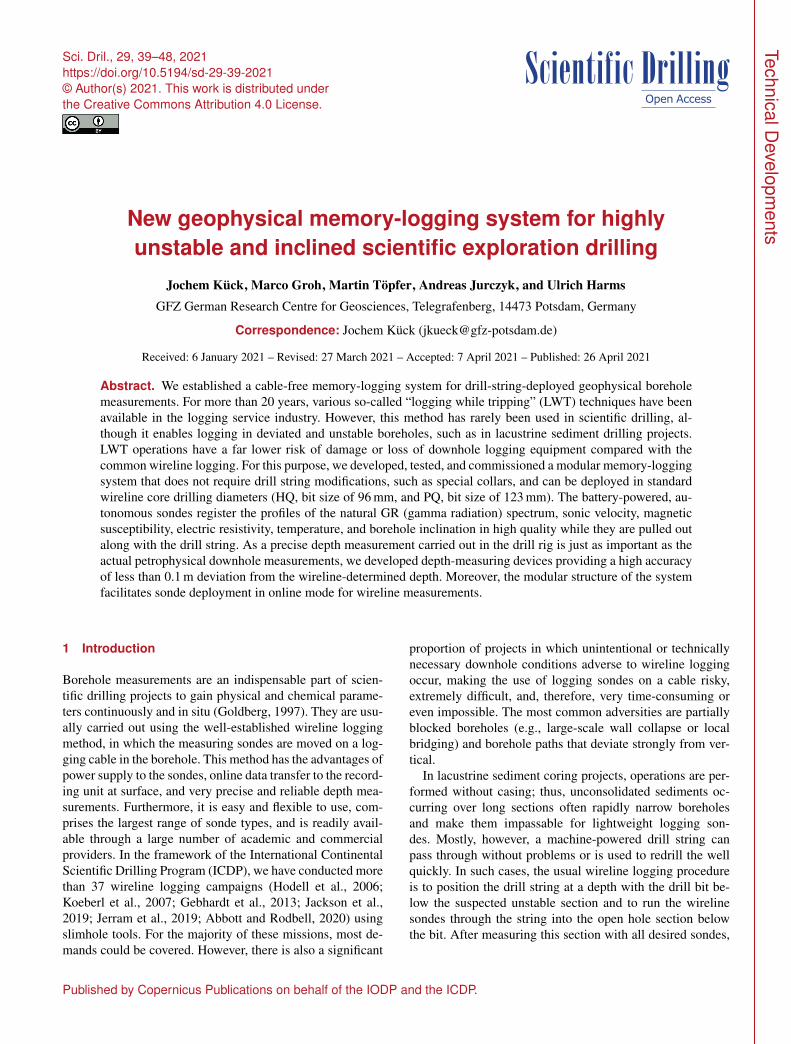
Figure 1. Representation of the logging while tripping (LWT)method in a lake coring setup: (a) dropping the ICDP memory-logging system (iMLS) in the drill string, (b) landing the iMLS inthe outer core barrel at the drill bit, (c) trip-out of the drill stringand alongside logging with the iMLS, and (d) reading out the datafrom the iMLS sonde memory and the iMLS depth-measuring de-vice (iDMD).
uous, evenly decreasing depth profile of the downhole pa-rameter. The LWT depth measurement in the drill rig is sim-ilar to the LWD depth determination; however, in the lat-ter, the entire running-in of the drill string is measured fromits very beginning at the derrick floor. LWT depth measure-ments can only begin when the last core has been drilled andbrought to surface, i.e., the drill string has already been in theborehole for many core runs.
For LWT systems, the risks described above for wirelinesondes are virtually negligible when running through unsta-ble zones, because the tools only partially stick out of thecore bit into the open hole. Moreover, the upper part of thetools always remains secure inside the drill string, which,on the one hand, completely eliminates the reentry risk and,on the other hand, minimizes exposure to the unstable hole.Should the LWT nevertheless get stuck, drillers can circulatedrill mud through the drill bit in order to remove the block-age, and the tools in the drill string can easily be pulled withthe high force of the drill rig. Under regular working condi-tions, the tool string can be retrieved at any time using thecore retrieval device (coring wire line and overshot) – for ex-ample, if only a partial section of the borehole is to be loggedor if technical drilling problems should arise.
Different variants of the logging while tripping methodare used commercially worldwide (e.g., Aivalis et al., 2012;Beal, 2019). In the most widespread method, a special mod-
Sci. Dril., 29, 39–48, 2021 https://doi.org/10.5194/sd-29-39-2021
J. Kück et al.: New geophysical memory-logging system for highly unstable and inclined scientific drilling 41
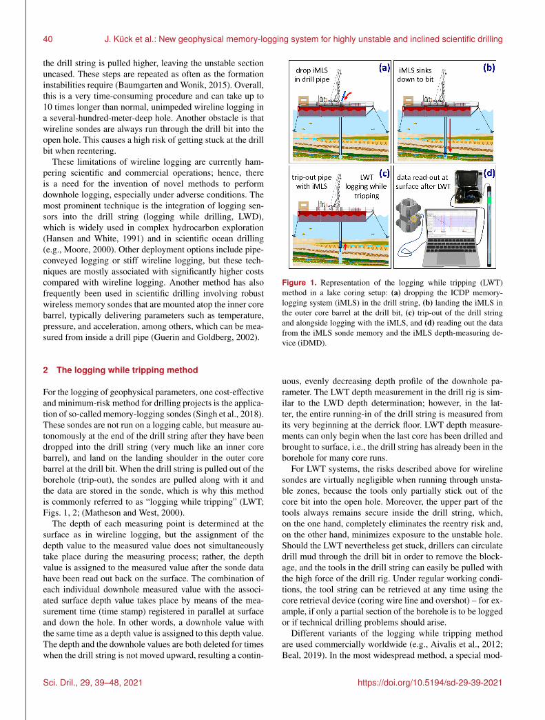
Figure 2. Sketch of a standard ICDP memory-logging system(iMLS) tool combination landed at the bottom of the drill string,partially sticking out into the open hole in a ready-to-log position(not to scale).
ified drill collar above the drill bit allows for the logging ofsome parameters from entirely within the pipe so that thelogging tools never run into the open hole. Since 2012, a setof specially designed memory sondes have been deployedwith the MeBo ocean floor drilling robot (Freudenthal et al.,2020), with most of the logging tools actually protruding outof the drill bit into the open hole. Having been involved inthe very early development of the MeBo memory sondes,we used this successful example to develop, in cooperationwith the same sonde manufacturer (ANTARES GmbH, Ger-many), a new and improved memory-logging sonde systemmotivated by a high demand for LWT capabilities in scien-tific drilling and a lack of affordable commercial LWT ser-vices.
3 The ICDP memory-logging system (iMLS)
The LWT system that we designed consists (from top to bot-tom) of a landing unit which can be adapted to different drillstring dimensions, five combinable single memory sondes,and a precise, robust, and field-application-friendly depth-measuring device at the surface (Figs. 2, 3, 4).
3.1 The landing unit
This uppermost component of the iMLS tool string ismounted directly on the logging sondes. The purely mechan-ical landing unit is required to correctly position the actualmeasuring sondes inside and below the drill pipe. The unitconsists of a fishing neck like that of an inner core barrel(Boart Longyear type), fitting pieces of different lengths, anda spring-loaded landing plate (Fig. 3). The modularity of thelanding unit enables the use of the iMLS in various core drillstrings with different bottom hole assembly geometry (outercore barrel and drill bit). Here, the length of the landing unit,the diameter of the landing plate, the hole size in the plate,and the stiffness of the impact suspension (spiral spring) aremodified according to the length and the inner diameter of theouter core barrel. These exchanges can easily be done at thedrill site, i.e., a change from PQ (bit size of 123 mm) to HQ(bit size of 96 mm) takes no more than 15 min. However, fit-ting rods for specific core barrel lengths have to be manufac-tured in advance. The iMLS is optimized for use in a wirelinecoring string with classic HQ dimensions (bit size of 96 mm),which is typical in ICDP drilling projects. With small adjust-ments, it can also be used in a larger PQ drill string (123 mm)and, with restrictions, in a smaller NQ string (76 mm). Thesuspension spring reduces the impact shock when the iMLSlands on the landing shoulder of the outer core barrel. Unlikean inner core barrel, which is anchored both downwards andupwards inside the outer core barrel, the landing plate doesnot latch; thus, the iMLS remains free upwards. This allowsthe sonde to give way upwards into the string should it ac-cidentally be lowered and touch the well bottom or an ob-struction. The descent rate of the sonde string inside the drillstring is reduced by using an adapted landing plate design tochange the flow resistance for a gentle and safe landing. Thesituation is different in strongly inclined bores with a devia-tion from vertical of > 50◦ where the weight of the sondes isusually no longer sufficient to overcome friction and to causethe sondes to stop sliding down the drill string. In such cases,the iMLS can be actively pumped down the pipe with thedrill mud circulation until it lands on the drill bit.
3.2 The sondes
Based on proven wireline slimhole sondes, the iMLS sondeswere further developed for autonomous memory measure-ments. These are so-called slimhole tools with a maximumouter diameter of 52 mm. All of the sondes can register at
https://doi.org/10.5194/sd-29-39-2021 Sci. Dril., 29, 39–48, 2021
42 J. Kück et al.: New geophysical memory-logging system for highly unstable and inclined scientific drilling
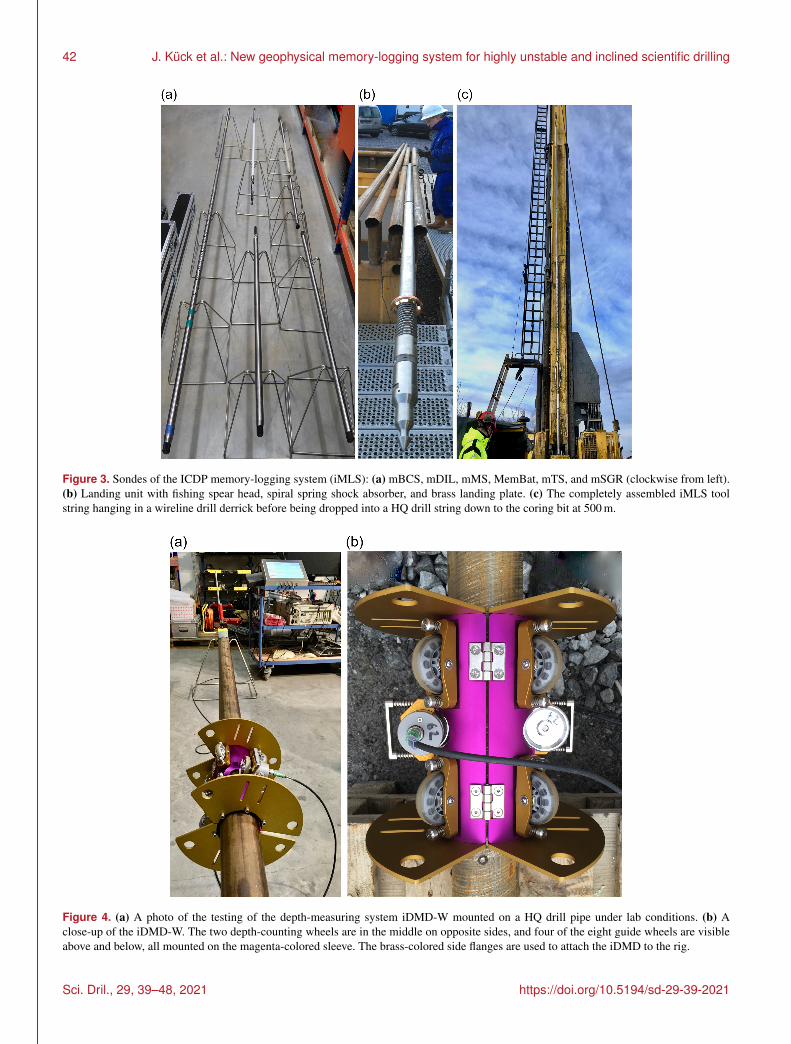
Figure 3. Sondes of the ICDP memory-logging system (iMLS): (a) mBCS, mDIL, mMS, MemBat, mTS, and mSGR (clockwise from left).(b) Landing unit with fishing spear head, spiral spring shock absorber, and brass landing plate. (c) The completely assembled iMLS toolstring hanging in a wireline drill derrick before being dropped into a HQ drill string down to the coring bit at 500 m.
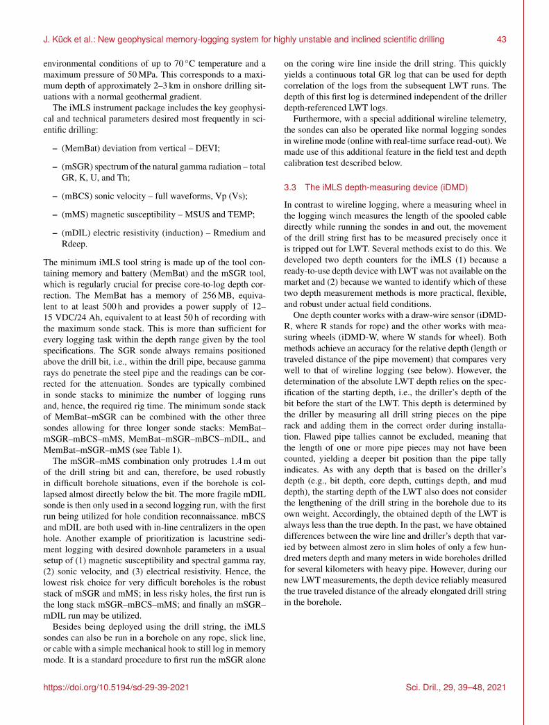
Figure 4. (a) A photo of the testing of the depth-measuring system iDMD-W mounted on a HQ drill pipe under lab conditions. (b) Aclose-up of the iDMD-W. The two depth-counting wheels are in the middle on opposite sides, and four of the eight guide wheels are visibleabove and below, all mounted on the magenta-colored sleeve. The brass-colored side flanges are used to attach the iDMD to the rig.
Sci. Dril., 29, 39–48, 2021 https://doi.org/10.5194/sd-29-39-2021
J. Kück et al.: New geophysical memory-logging system for highly unstable and inclined scientific drilling 43
environmental conditions of up to 70 ◦C temperature and amaximum pressure of 50 MPa. This corresponds to a maxi-mum depth of approximately 2–3 km in onshore drilling sit-uations with a normal geothermal gradient.
The iMLS instrument package includes the key geophysi-cal and technical parameters desired most frequently in sci-entific drilling:
– (MemBat) deviation from vertical – DEVI;
– (mSGR) spectrum of the natural gamma radiation – totalGR, K, U, and Th;
– (mBCS) sonic velocity – full waveforms, Vp (Vs);
– (mMS) magnetic susceptibility – MSUS and TEMP;
– (mDIL) electric resistivity (induction) – Rmedium andRdeep.
The minimum iMLS tool string is made up of the tool con-taining memory and battery (MemBat) and the mSGR tool,which is regularly crucial for precise core-to-log depth cor-rection. The MemBat has a memory of 256 MB, equiva-lent to at least 500 h and provides a power supply of 12–15 VDC/24 Ah, equivalent to at least 50 h of recording withthe maximum sonde stack. This is more than sufficient forevery logging task within the depth range given by the toolspecifications. The SGR sonde always remains positionedabove the drill bit, i.e., within the drill pipe, because gammarays do penetrate the steel pipe and the readings can be cor-rected for the attenuation. Sondes are typically combinedin sonde stacks to minimize the number of logging runsand, hence, the required rig time. The minimum sonde stackof MemBat–mSGR can be combined with the other threesondes allowing for three longer sonde stacks: MemBat–mSGR–mBCS–mMS, MemBat–mSGR–mBCS–mDIL, andMemBat–mSGR–mMS (see Table 1).
The mSGR–mMS combination only protrudes 1.4 m outof the drill string bit and can, therefore, be used robustlyin difficult borehole situations, even if the borehole is col-lapsed almost directly below the bit. The more fragile mDILsonde is then only used in a second logging run, with the firstrun being utilized for hole condition reconnaissance. mBCSand mDIL are both used with in-line centralizers in the openhole. Another example of prioritization is lacustrine sedi-ment logging with desired downhole parameters in a usualsetup of (1) magnetic susceptibility and spectral gamma ray,(2) sonic velocity, and (3) electrical resistivity. Hence, thelowest risk choice for very difficult boreholes is the robuststack of mSGR and mMS; in less risky holes, the first run isthe long stack mSGR–mBCS–mMS; and finally an mSGR–mDIL run may be utilized.
Besides being deployed using the drill string, the iMLSsondes can also be run in a borehole on any rope, slick line,or cable with a simple mechanical hook to still log in memorymode. It is a standard procedure to first run the mSGR alone
on the coring wire line inside the drill string. This quicklyyields a continuous total GR log that can be used for depthcorrelation of the logs from the subsequent LWT runs. Thedepth of this first log is determined independent of the drillerdepth-referenced LWT logs.
Furthermore, with a special additional wireline telemetry,the sondes can also be operated like normal logging sondesin wireline mode (online with real-time surface read-out). Wemade use of this additional feature in the field test and depthcalibration test described below.
3.3 The iMLS depth-measuring device (iDMD)
In contrast to wireline logging, where a measuring wheel inthe logging winch measures the length of the spooled cabledirectly while running the sondes in and out, the movementof the drill string first has to be measured precisely once itis tripped out for LWT. Several methods exist to do this. Wedeveloped two depth counters for the iMLS (1) because aready-to-use depth device with LWT was not available on themarket and (2) because we wanted to identify which of thesetwo depth measurement methods is more practical, flexible,and robust under actual field conditions.
One depth counter works with a draw-wire sensor (iDMD-R, where R stands for rope) and the other works with mea-suring wheels (iDMD-W, where W stands for wheel). Bothmethods achieve an accuracy for the relative depth (length ortraveled distance of the pipe movement) that compares verywell to that of wireline logging (see below). However, thedetermination of the absolute LWT depth relies on the spec-ification of the starting depth, i.e., the driller’s depth of thebit before the start of the LWT. This depth is determined bythe driller by measuring all drill string pieces on the piperack and adding them in the correct order during installa-tion. Flawed pipe tallies cannot be excluded, meaning thatthe length of one or more pipe pieces may not have beencounted, yielding a deeper bit position than the pipe tallyindicates. As with any depth that is based on the driller’sdepth (e.g., bit depth, core depth, cuttings depth, and muddepth), the starting depth of the LWT also does not considerthe lengthening of the drill string in the borehole due to itsown weight. Accordingly, the obtained depth of the LWT isalways less than the true depth. In the past, we have obtaineddifferences between the wire line and driller’s depth that var-ied by between almost zero in slim holes of only a few hun-dred meters depth and many meters in wide boreholes drilledfor several kilometers with heavy pipe. However, during ournew LWT measurements, the depth device reliably measuredthe true traveled distance of the already elongated drill stringin the borehole.
https://doi.org/10.5194/sd-29-39-2021 Sci. Dril., 29, 39–48, 2021
44 J. Kück et al.: New geophysical memory-logging system for highly unstable and inclined scientific drilling
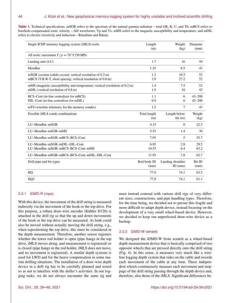
Table 1. Technical specifications. mSGR refers to the spectrum of the natural gamma radiation – total GR, K, U, and Th; mBCS refers toborehole-compensated sonic velocity – full waveforms, Vp and Vs; mMS refers to the magnetic susceptibility and temperature; and mDILrefers to electric resistivity and induction – Rmedium and Rdeep.
Single ICDP memory-logging system (iMLS) tools Length Weight Diameter(m) (kg) (mm)
All tools: maximum T/p = 70 ◦C/50 MPa
Landing unit (LU) 1.7 16 50
MemBat 1.25 6.5 43
mSGR (cesium iodide crystal; vertical resolution of 0.2 m) 1.2 10.3 52mBCS (T-R-R-T, short spacing; vertical resolution of 0.6 m) 3.9 27.2 52
mMS (magnetic susceptibility and temperature; vertical resolution of 0.2 m) 1.4 7.5 52mDIL (vertical resolution of 0.8 m) 1.9 10 43
BCS–Cent (in-line centralizer for mBCS) 1.1 6 43–200DIL–Cent (in-line centralizer for mDIL) 0.9 6 43–200
mTS (wireline telemetry for the memory sondes) 1.5 7 43
Possible iMLS sonde combinations Total length Length below Weight(m) bit (m) (kg)
LU–MemBat–mSGR 4.15 0 22.5
LU–MemBat–mSGR–mMS 5.55 1.4 30
LU–MemBat–mSGR–mBCS–BCS–Cent 7.95 5 55.7
LU–MemBat–mSGR–mDIL–DIL–Cent 6.95 2.8 29.5LU–MemBat–mSGR–mBCS–BCS–Cent–mMS 10.55 6.4 63.2
LU–MemBat–mSGR–mBCS–BCS–Cent–mDIL–DIL–Cent 11.95 7.8 62.7
Drill pipe and bit types Rod body ID Landing shoulder Bit ID(mm) ID (mm) (mm)
HQ 77.8 74.1 63.5
HQ3 77.8 74.1 61.1
3.3.1 iDMD-R (rope)
With this device, the movement of the drill string is measuredindirectly via the movement of the hook or the top drive. Forthis purpose, a robust draw-wire encoder (Kübler D120) isattached in the drill rig so that the up and down movementsof the hook or the top drive can be measured. As both couldalso be moved without actually moving the drill string, e.g.,when repositioning the top drive, this must be considered inthe depth measurement. Therefore, another sensor registerswhether the lower rod holder is open (pipe hangs in the topdrive, iMLS moves along, and measurement is registered) oris closed (pipe hangs in the rod holder, iMLS does not move,and no movement is registered). A similar depth systems isused for LWD and for the heave compensation in some ma-rine drilling situations. The installation of a draw-wire depthdevice in a drill rig has to be carefully planned and testedso as not to interfere with the driller’s activities. In our log-ging tasks, we do not always encounter the same rig and
must instead contend with various drill rigs of very differ-ent sizes, constructions, and pipe handling types. Therefore,for the time being, we decided not to pursue this fragile andmore difficult-to-adapt depth device, instead focusing on thedevelopment of a very small wheel-based device. However,we decided to keep our unperfected draw-wire device as abackup.
3.3.2 iDMD-W (wheel)
We designed the iDMD-W from scratch as a wheel-baseddepth measurement device that is basically comprised of twoopposite wheels that are pressed directly onto the drill string(Fig. 4). In this sense, it measures very much like a wire-line logging depth system that rides on the cable and recordseach movement of the cable at any time. These indepen-dent wheels continuously measure each movement and stop-page of the drill string passing through the depth device and,therefore, also those of the iMLS. Significant differences be-
Sci. Dril., 29, 39–48, 2021 https://doi.org/10.5194/sd-29-39-2021
J. Kück et al.: New geophysical memory-logging system for highly unstable and inclined scientific drilling 45
tween the two readings make it possible to immediately rec-ognize errors in the depth measurement. Errors could occurif a friction-reducing fluid caused the measuring wheels tooccasionally slide on the drill string, which, in turn, wouldmean that the determined distances would be too short. Intests, one of the wheels was kept dry and the other wheel wasmoistened with water and with oil; these treatments did notcause any visible differences between the two length mea-surements. During measurement, the readings of both wheelsare recorded and the larger value is chosen as the final depthoutput. This very compact and robust device is mounted likea sleeve around the drill string. The aluminum sleeve carrieseight guide rollers and the two opposite measuring wheels.Due to its compactness, it can be installed in a position pro-tected against damage between the top of the standpipe andthe drill rod holder in a typical mining drill rig such as theICDP DLDS (Deep Lakes Drilling System).
4 Field test and results
The technical functionality with respect to memory and wire-line operation, pressure and temperature resistance, and han-dling of all iMLS sondes was verified in the 4000 m deep testborehole of the KTB Depth Laboratory (Harms and Kück,2020).
The goal of the first full field utilization of the entire iMLSsystem was twofold: on the one hand, we aimed to check andimprove the procedure that we had designed; on the otherhand, we wished to examine the accuracy of the iMLS depthmeasurement method. The key operational objective was toexercise the complete LWT procedure for the first time, in-volving all components, and to compare the log depths ob-tained with those from subsequent wireline logging runs ofthe same memory sondes.
The field performance test was conducted during the activedrilling operations at the 1000 m deep I-EDDA Test Centerwell (Almqvist et al., 2018). In cooperation with the drill rigoperator, iMLS tests were carried out under realistic condi-tions in the depth range from 0 to 500 m. At the beginningof the test, the HQ core drill string was already installedin the hole with the coring bit at 500 m. First, a mechani-cal test was carried out with a dummy sonde, consisting ofthe landing unit and a solid steel bar with the dimensionsand weight of an iMLS sonde string. After confirming the re-silience and retrievability of the landing unit, the actual iMLSlogging in memory mode was carried out along the depthsection from 500 to 390 m with the long sonde combinationof LU–MemBat–mSGR–mBCS–BCS–Cent–mMS (Fig. 3).A wheel-based depth counter prototype and the draw-wiredevice were used one after the other. The iDMD-W describedabove was not yet available at that time. The large size of thewheel-prototype only allowed for a mounting position be-tween the rod holder and the top drive. Unfortunately, theprototype was rammed by the downward-moving top drive
after only 8 m of pipe tripping and became unusable, where-upon the iDMD-R was used. After the complete trip-out ofthe drill string, we ran the iMLS sondes in wireline mode inthe open hole using a 600 m logging winch. We ran the samesonde stack as that used in LWT memory mode for the wire-line mode logging. As the sondes and the logging speed wereidentical in memory and wireline logging, the logs show thesame values and amplitudes, although their depth positionsmay have differed due to the very unequal depth-measuringmethod. The direct comparison of memory and wireline logswas then used to estimate the accuracy of the memory depth.The depth of the wireline log can be assumed to be almostequal to true depth because the TC1 hole is vertical and hasa very smooth wall surface at these shallow depths.
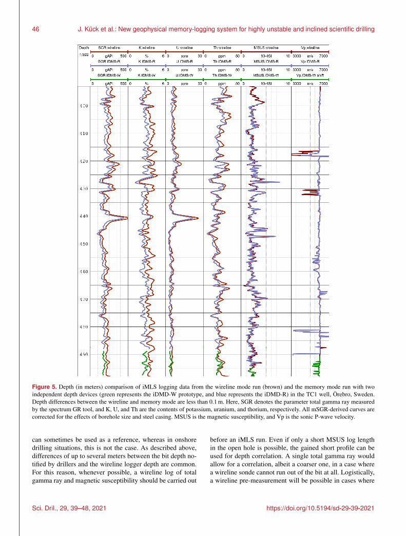
When comparing wireline and memory logs, the memorydepth first had to be shifted by a constant value using sim-ple visual correlation due to the inexact starting depth in-formation (drill bit depth) of the memory registrations. Themagnetic susceptibility log (MSUS) was best suited to thistask due to the almost complete reproduction of its profilein repeat measurements and its high vertical resolution ofless than 0.1 m. Depth offsets for correction to the wirelinedepth were calculated as+4.6 m for the wheel prototype and+8.8 m for the iDMD-R. After this correction of the start-ing depth, the comparison of the wireline and the memorylogs shows a remarkably good agreement of the depth of themeasured curves (Fig. 5). The logs are only used here for thepurpose of depth correlation. A detailed evaluation of theseand additional geophysical logs along with core-derived datais the subject of ongoing investigations.
The excellent depth match is most evident in thehigh-depth-resolution curves of the magnetic susceptibility(MSUS), which almost overlay each other. The average depthdifference is 0.2 m, which is in the order of the sample spac-ing of 0.1 m. Furthermore, the four parameters of the naturalgamma ray spectrum sonde mSGR (total SGR; potassium, K;uranium, U; and thorium, Th) show a very good depth corre-lation of memory and wireline curves. All mSGR curves arecorrected for the small hole size, and the memory curves areadditionally corrected for the attenuation by the drill pipe.Slight differences in the curve shapes are due to the statis-tical nature of the natural gamma radiation as a product ofradioactive decay. The P-wave velocity curves (Vp) of thesonic tool also show a good log–log correlation except forsmall divergences in a few short zones resulting from thedifficult-to-process sonic waveform data.
The depth differences are less than 0.1 m along the 100 mlong section. This demonstrates the ability of the iMLS depthdevices to determine the movement of the sonde string inthe borehole with the same accuracy and resolution as theclassic wireline method. However, it also shows how im-mensely important the reliability of the exact starting depthreported by the driller is for LWT, without which an absoluteLWT depth determination is impossible; for example, in lakedrilling projects, the drop in the total GR at the lake floor
https://doi.org/10.5194/sd-29-39-2021 Sci. Dril., 29, 39–48, 2021
46 J. Kück et al.: New geophysical memory-logging system for highly unstable and inclined scientific drilling
Figure 5. Depth (in meters) comparison of iMLS logging data from the wireline mode run (brown) and the memory mode run with twoindependent depth devices (green represents the iDMD-W prototype, and blue represents the iDMD-R) in the TC1 well, Örebro, Sweden.Depth differences between the wireline and memory mode are less than 0.1 m. Here, SGR denotes the parameter total gamma ray measuredby the spectrum GR tool, and K, U, and Th are the contents of potassium, uranium, and thorium, respectively. All mSGR-derived curves arecorrected for the effects of borehole size and steel casing. MSUS is the magnetic susceptibility, and Vp is the sonic P-wave velocity.
can sometimes be used as a reference, whereas in onshoredrilling situations, this is not the case. As described above,differences of up to several meters between the bit depth no-tified by drillers and the wireline logger depth are common.For this reason, whenever possible, a wireline log of totalgamma ray and magnetic susceptibility should be carried out
before an iMLS run. Even if only a short MSUS log lengthin the open hole is possible, the gained short profile can beused for depth correlation. A single total gamma ray wouldallow for a correlation, albeit a coarser one, in a case wherea wireline sonde cannot run out of the bit at all. Logistically,a wireline pre-measurement will be possible in cases where
Sci. Dril., 29, 39–48, 2021 https://doi.org/10.5194/sd-29-39-2021
J. Kück et al.: New geophysical memory-logging system for highly unstable and inclined scientific drilling 47
the iMLS serves as a backup for the primary preferred wire-line measurements. This procedure is not possible in stronglyinclined bores. Ultimately, even without an absolute depthreference (e.g., wireline depth), the LWT depth will instan-taneously match the core depth, as both refer to the driller’sdepth.
Although our system is now basically ready for regular usein HQ and PQ holes, we will use both our iMLS and wirelinelogging systems in upcoming projects to carry out furthertests of the depth-recording device in comparison to wirelinelogging in order to improve the iMLS performance and toverify the observed accuracy of the memory depth measure-ment on a broader statistical basis.
Data availability. This report is a technical description of theICDP memory-logging system. For information on the availabil-ity of the iMLS and conditions for use see the SUPPORT sectionof the ICDP website (https://www.icdp-online.org/support/service/downhole-logging/operational-support/, last access: 17 April2021). Logging data presented in this report are preliminary and arenot yet publicly available, as they are still being evaluated. Uponcompletion, all data will be made available when the associated sci-entific papers and reports are published.
Author contributions. JK planned and led this project and allfield tests. MG designed the landing unit, the depth devices, andthe software. AJ provided machine drawings of the landing unit andthe wheel depth device. MG and MT tested and improved the en-tire system in the lab and in the field tests. JK and UH managed theproject and designed the paper. All authors contributed to the paper.
Competing interests. The last author is editor-in-chief of Scien-tific Drilling; all other authors declare that they have no conflict ofinterest.
Disclaimer. Any use of trade, firm, or product names is for de-scriptive purposes only.
Acknowledgements. We thank Jan-Erik Rosberg, Johan Kullen-berg, Simon Rejkjär, and Peter Jonsson from the University ofLund, Sweden, for their patience and tireless help with preparingand undertaking the field test. The reviews of Gilles Guerin andDavid Goldberg contributed to the improvement of this report.
Financial support. Development, manufacturing, and acquisitionof the iMLS were funded by the International Continental Scien-tific Drilling Program, ICDP. The field campaign has been fundedby the EIT Raw Materials project: Innovative Exploration Drillingand Data Acquisition Test Center – I-EDDA-TC (grant agreementEIT/RAW MATERIALS/SGA2019/1).
Review statement. This paper was edited by Tomoaki Morishitaand reviewed by David Goldberg and Gilles Guerin.
References
Abbott, M. B. and Rodbell, D. T.: Stratigraphic correlation andsplice generation for sediments recovered from a large-lakedrilling project: an example from Lake Junín, Peru, J. Paleolim-nol., 63, 83–100, https://doi.org/10.1007/s10933-019-00098-w,2020.
Aivalis, J., Meszaros, T., Porter, R., Reischman, R., Ridley,R.,Wells, P., Crouch, B. W., Reid, T. L., and Simpson, G. A.: Log-ging Through the Bit, Oilfield Review Summer 2012, 24, 44–53,2012
Almqvist, B., Brander, L., Giese, R. Harms, U., Juhlin, C., Linde´n,C., Lorenz, H., and Rosberg, J.: I-EDDA test center for core-drilling and downhole investigations, EGU General Assembly2018, 8–13 April 2018, Vienna, Austria, Geophysical ResearchAbstracts, 20, EGU2018-14837, 2018.
Baumgarten, H. and Wonik, T.: Cyclostratigraphic studies ofsediments from Lake Van (Turkey) based on their ura-nium contents obtained from downhole logging and pale-oclimatic implications, Int. J. Earth Sci., 104, 1639–1654,https://doi.org/10.1007/s00531-014-1082-x, 2015.
Beal, J.: Tight oil vertical log analysis applied to horizontal LoggingWhile Tripping (LWT) data of Cretaceous-aged Viking forma-tion, Saskatchewan, Canada: a multi-disciplinary review of initialand extended findings, AAPG Rocky Mountain Section Meeting,Cheyenne, WY, USA, 2019.
Freudenthal, T., Bohrmann, G., Gohl, K., Klages, J. P., Riedel, M.,Wallmann, K., and Wefer, G.: More than ten years of success-ful operation of the MARUM-MeBo sea bed drilling technology:Highlights of recent scientific drilling campaigns, EGU GeneralAssembly, Online Conference, 4–8 May 2020, SSP1.4, 2020.
Gebhardt, A. C., Francke, A., Kück, J., Sauerbrey, M., Niessen,F., Wennrich, V., and Melles, M.: Petrophysical characteri-zation of the lacustrine sediment succession drilled in LakeEl’gygytgyn, Far East Russian Arctic, Clim. Past, 9, 1933–1947,https://doi.org/10.5194/cp-9-1933-2013, 2013.
Goldberg, D.: The Role of Downhole Measurements in Ma-rine Geology and Geophysics, Rev. Geophys., 35, 315–342,https://doi.org/10.1029/97RG00221, 1997.
Guerin, G. and Goldberg, D.: Heave compensation and for-mation strength evaluation from downhole accelerationmeasurements while coring, Geo-Mar. Lett., 22, 133–141,https://doi.org/10.1007/s00367-002-0104-z, 2002.
Hansen, R. R. and White, J.: Features of Logging-While-Drilling(LWD) in Horizontal Wells, SPE/IADC Drilling Conference,11–14 March 1991, Amsterdam, the Netherlands, 21989-MS,https://doi.org/10.2118/21989-MS, 1991.
Harms, U. and Kück, J.: KTB Depth Laboratory: A Window intothe Upper Crust, in: Encyclopedia of Solid Earth Geophysics,Encyclopedia of Earth Sciences Series, edited by: Gupta, H. K.,https://doi.org/10.1007/978-3-030-10475-7_242-1, 2020.
Hodell, D., Anselmetti, F., Brenner, M., Ariztegui, D.,and the PISDP Scientific Party: The Lake PeténItzá Scientific Drilling Project, Sci. Dril., 3, 25–29,https://doi.org/10.2204/iodp.sd.3.02.2006, 2006.
https://doi.org/10.5194/sd-29-39-2021 Sci. Dril., 29, 39–48, 2021
48 J. Kück et al.: New geophysical memory-logging system for highly unstable and inclined scientific drilling
Jackson, M. D., Gudmundsson, M. T., Weisenberger, T. B., Rhodes,J. M., Stefánsson, A., Kleine, B. I., Lippert, P. C., Marquardt,J. M., Reynolds, H. I., Kück, J., Marteinsson, V. T., Vannier,P., Bach, W., Barich, A., Bergsten, P., Bryce, J. G., Cappel-letti, P., Couper, S., Fahnestock, M. F., Gorny, C. F., Grimaldi,C., Groh, M., Gudmundsson, Á., Gunnlaugsson, Á. T., Ham-lin, C., Högnadóttir, T., Jónasson, K., Jónsson, S. S., Jørgensen,S. L., Klonowski, A. M., Marshall, B., Massey, E., McPhie, J.,Moore, J. G., Ólafsson, E. S., Onstad, S. L., Perez, V., Prause, S.,Snorrason, S. P., Türke, A., White, J. D. L., and Zimanowski,B.: SUSTAIN drilling at Surtsey volcano, Iceland, tracks hy-drothermal and microbiological interactions in basalt 50 yearsafter eruption, Sci. Dril., 25, 35–46, https://doi.org/10.5194/sd-25-35-2019, 2019.
Jerram, D. A., Millett, J. M., Kück, J., Thomas, D., Planke, S., Hask-ins, E., Lautze, N., and Pierdominici, S.: Understanding volcanicfacies in the subsurface: a combined core, wireline logging andimage log data set from the PTA2 and KMA1 boreholes, BigIsland, Hawai‘i, Sci. Dril., 25, 15–33, https://doi.org/10.5194/sd-25-15-2019, 2019.
Koeberl, C., Milkereit, B., Overpeck, J. T., Scholz, C., Amoako,P. Y. O., Boamah, D., Danuor, S., Karp, T., Kück, J., Hecky, R.E., King, J. W., and Peck, J. A.: An international and multidis-ciplinary drilling project into a young complex impact structure:The 2004 ICDP Bosumtwi Crater Drilling Project – An overview,Meteorit. Planet. Sci., 42, 483–511, 2007.
Matheson, R. and West, J.: Logging While Tripping – A New Al-ternative in Formation Evaluation, J. Can. Petrol. Technol., 39,38–43, https://doi.org/10.2118/00-07-02, 2000.
Moore, J. C.: Synthesis of results: logging while drilling,northern Barbados accretionary prism, in: Proc. ODP, Sci.Results, 171A: College Station, TX (Ocean Drilling Pro-gram), edited by: Moore, J. C. and Klaus, A., 1–25,https://doi.org/10.2973/odp.proc.sr.171a.101.2000, 2000.
Singh, M., Al Benali, K., A., Sallam, Y., Sajeel, K., El Wazeer, F.,Chaker, H., and Propper, M.: A Case Study on Open-Hole Log-ging While Tripping LWT Through Drill Pipes, as a New Tech-nology for Risk Mitigation and Cost Optimization in Abu DhabiOnshore Fields, Society of Petroleum Engineers, SPE-193315-MS, https://doi.org/10.2118/193315-MS, 2018.
Sci. Dril., 29, 39–48, 2021 https://doi.org/10.5194/sd-29-39-2021