Embed Size (px)
Citation preview

DTC-02/138 Page 1
ELETTRONICA S.p.A.
By: Dr. Alfredo BacchelliStrategic Marketing Director
Elettronica SpARoma, ITALY
New technologies and innovative techniques for
new-generation ECM systems
DTC-02/138 Page 2
Summary• Self-Protection ECM systems presently installed onboard NATO
forces’ aircraft and ships have demonstrated in several occasions a good level of effectiveness, but the continual evolution of radar-guided threats demands for a parallel evolution of the ECM assets
• This paper describes two recent examples of this evolution:
A new ECM-system architecture, developed by Elettronica SpAof Roma (ITALY), taking advantage of its latest achievements in various fields: antenna design, solid-state high-power micro-wave amplifiers and high-density circuit packaging
Use of this architecture to implement, in a real system, innova-tive ECM techniques such as Cross-Eye & Cross-Pol, the first having been successfully demonstrated in the frame of a long-term cooperation between Elettronica and the Italian MOD

DTC-02/138 Page 3
The BackgroundFrom the beginning of its activity in the EW field, about 50 years ago,Elettronica designed and produced ECM systems to be installedonboard various types of military platforms:
– aircraft & helicopters (self & mutual protection ECM)– military ships (self defence ECM)– ground mobile stations (point/area defence ECM)

DTC-02/138 Page 4
ECM Transmitter technology• In most Radar Jammers of traditional design, RF power amplifica-
tion was provided by vacuum tubes (typically TWTs) and ECM signals were in general radiated through single-beam antennas
• Drawbacks and limitations of this HW approach are well known:– Long “warm-up” time (from switch-on to transmission) – Tx reliability often unsatisfactory, mainly due to TWT’s high-
voltage requirement of and to their limited life– Reliable operation at high altitude (or in high-humidity environ-
ment), can be obtained only through a very smart Tx design– Multi-threat ECM capability is often limited to a maximum of
two simultaneous threats, especially when the ECM signal is radiated through high-gain single-beam antennas
– Demanding logistic support (mainly due to use of limited-life components: primarily the TWT transmitting tubes)
– High through-life cost

DTC-02/138 Page 5
PHASED-ARRAY ANTENNAS
• Phased-array technique, with the possibility of electronic beam aiming, permits to design ECM systems capable of simultaneous ECM reactions against multiple threats, in various directions
• NETTUNO system has been the first Elettronica’s naval ECM product using this solution
• However, the other problems recalled above and all related to the use of TWTs, remained un-solved Nettuno System’s ECM antennas, onboard
the Italian-Navy carrier “Garibaldi”

DTC-02/138 Page 6
Modern Anti-Ship Missile Threats

DTC-02/138 Page 7
New threats and new ECM needs• To effectively counter the new radar and missile threats, ECM systems
must have features that were in general not implemented (or not avail-able all together), in the previous generation systems:– Effectiveness against all modern radar types (for both search and
tracking, including coded, coherent and monopulse types)– Capability of multiple reactions against multiple simultaneous
threats, in different RF bands and coming from different directions– Capability of electronic ECM-beam aiming not only to any azimuth,
but also to any elevation angle, within a wide overall field– Very high “mission success probability” , which implies:
• high reliability and availability, • good failure resistance, • minimisation (or total absence) of limited life components and
of mechanical moving parts, • simple and fast maintenance
1
2
3
4

DTC-02/138 Page 8
DRFM “Exciters”: the key ECM resource against coded/coherent threat radars
I/O PRITRACKERS
DIGITALMEMORY
I/O
DIGITALMEMORY
LO
T/R SWITCH TO/FROM
ANTENNA
DRFM
DESIGNATIONFROM ESM
LOCAL BUS
CPU

DTC-02/138 Page 9
“ECM Exciters” using DRFM
• As phased-array technique has been the key element to implement multi-threat jammers, the use of DRFM improved in a significant manner the ECM system capability to jam (or to deceive) coded or coherent radars and missile-seekers
• The first DRFM produced by Elettronica (1993-95) was a 2-bit model, originally used for an airborne self-protec-tion jammer (ELT/553) →
ELT/553(V)3 SPJTechniques Generator
DRFM board
Wideband RF tuning module
DTC-02/138 Page 10
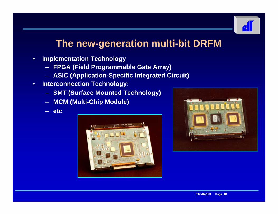
The new-generation multi-bit DRFM• Implementation Technology
– FPGA (Field Programmable Gate Array)– ASIC (Application-Specific Integrated Circuit)
• Interconnection Technology:– SMT (Surface Mounted Technology)– MCM (Multi-Chip Module)– etc

DTC-02/138 Page 11
The EFA project: a great opportunity fora step ahead in ECM technology
• When EFA project was launched, at the end of the ‘80s, Solid-State ECM was the “dream in the drawer” of many EW designers
• Potential benefits of Solid-State technology, if used to design an active-array ECM antenna, were (and are) extremely attractive:– feasibility of arrays with very wide space coverage– true modularity in terms of ERP – high overall efficiency (power consumption versus ERP)– better EMC behaviour for a given ERP (interoperability)– elimination of high voltage power supply– extremely high reliability and fault tolerance – simplified logistics and lower through-life cost
• Semiconductor technology for power amplification in microwave band was progressing, although in a rather slow manner

DTC-02/138 Page 12
The road to the “Solid-State ECM”• In the EFA project requirements, the ERP level and the other per-
formance specifications, though demanding, were matching with the possible features of an active phased array solution
• At that time the Output Power available from solid-state amplifiers was just sufficient to reach the specified ERP with a “realistic” active phased-array solution, but it was promising to grow by a few more dB in the years to come, during system development
• Time and money for an innovative development were available• On these assumptions, Elettronica defined a fully solid-state SPJ
(Self-Protection Jammer), compliant with the EFA requirement• Then ELT established an alliance with GEC Marconi (now BAE-
Systems) in a consortium named Eurodass; they jointly prepared a fully solid-state DASS proposal for EFA and won the tender:
The first all-solid-state ECM project was launched

DTC-02/138 Page 13
From conventional Tx to Phased Array
Today, SSA architecture permits to obtain: • The same ERP “class” of TWT systems• Lower Weight & Power Consumption• Better A/ϕ stability & control• Better reliability and availabilityAs known, accurate & stable A/ϕ control is a key feature to implement Cross-Eye ECM
Today, SSA architecture permits to obtain: • The same ERP “class” of TWT systems• Lower Weight & Power Consumption• Better A/ϕ stability & control• Better reliability and availabilityAs known, accurate & stable A/ϕ control is a key feature to implement Cross-Eye ECM

DTC-02/138 Page 14
The Eurofighter EF-2000 “Typhoon”

DTC-02/138 Page 15
Power Supply Transceivers’ packet Transmitting/receivingantenna array
The EFA-DASS Antenna/Transceiver Unit(main item of Elettronica’s work-share)

DTC-02/138 Page 16
THE ANTENNA ARRAY(linear array of multi-notch Vivaldi elements)
One of the various experimental antenna arrays madeand extensively tested during system development

DTC-02/138 Page 17
THE TRANSCEIVER MODULE(From the feasibility demonstrator model
to the “pre-series” fully qualified units)
Years1990 1993 1997 2001
Inte
grat
ion
leve
l & O
utpu
t Pow
er

DTC-02/138 Page 18
TRANSCEIVER MODULE(The Pre-Production model)
The transceiver module already produced in small series for theSS-ECM systems delivered during the pre-production phase

DTC-02/138 Page 19
A new-generation airborne ECM system• The new Elettronica Modular Airborne ECM System consists of:
– A DRFM-based Techniques Generator, incorporating also the circuits for passive emitter tracking and the reaction-manage-ment computer
– Active Phased-Array (APA) antennas, in number sufficient to cover all the sectors of interest, each composed of the ap-propriate number of elements to produce the required ERP (Effective Radiated Power)
• The Techniques Generator may optionally include the circuits re-quired for implementation of Cross-Eye and of other ECM techni-ques requiring accurate amplitude, phase and polarisation control
• For each APA unit, two physical configurations are proposed:– the “Integral” one (as already seen for the EFA-DASS)– the “split” one, in which the packet of transceivers and the
array of radiating elements are two separate units

DTC-02/138 Page 20
An example of “split” SS-ECM structure: the HDJ-X ECM for Combat-Helicopters
• Helo RF/SPJ needs:– All-around protection– Instantaneous response– High ERP – Lightweight & low power
consumption units– High availability (fault
tolerant architecture)
• Solution: a Solid State ECM, composed of three “parts”:– a compact DRFM-based Exciter (not shown),– a single-unit transceiver assembly (A),– a multiple-array antenna assembly (B)
A B

DTC-02/138 Page 21
Operational Flexibility • Implementation of Cross-Eye (X/E) requires two ECM antennas for
each angular sector to be covered• This need, which in a first instance could be seen as a negative
cost-increase factor, gives the system (in addition to outstanding X/E capabilities against monopulse radars) also an excellent operational flexibility
• The two ECM antennas, in fact, may be used in various modes, either by co-operating in countering the same threats, or working independently one from the other, against different threats
• Due to system capabilities in terms of amplitude & phase control, “cooperative” modes are not limited to Cross-Eye, but include: – In-phase multi-threat jamming, with on-target ERP being 6 dB
higher than the value provided by a single APA antenna– Other non-conventional ECM techniques, made possible in
this system by its excellent signal control features

DTC-02/138 Page 22
Operational Flexibility: an example
In this aircraft, each pair of ECM an-tennas covering the same FOV (i.e. the Front or Rear sector) can be used in either independent or co-operative reaction mode, according to real-time mission needs
♦ In “independent” mode, the two anten-nas may provide fully independent reaction against different threats. As an example, one antenna may jam one threat with continuous noise, while the other reacts to other threats
♦ In co-operative mode, the system permits three alternative multi-threat capabilities:
In-phase combined-power ECM (with on-target power increase of 6 dB)On-Target Phase-opposition ECM (for Cross-Eye angular deception)Other “non-conventional” ECM techniques, (which however may require modified antenna elements)
FOV
-FFO
V-F
FOV
-RFO
V-R

DTC-02/138 Page 23
Solid-State Technology for Naval ECM too

DTC-02/138 Page 24
Effective Radiated Power (ERP) Requirement in today’s naval scenario
• When the first hypothesis of a solid-state naval jammer was made, the first quite unanimous comment was: “No! You cannot get from these stupid transistors enough power for a “serious” naval ECM”
• As we will see, this statement is wrong: today’s solid-state techno-logy permits to get from a fully solid-state naval jammer the same ERP of the TWT-based ECM systems now present on the market
• For the same ERP class, however, the new solid-state jammersfrom ELT are lighter in weight, definitely smaller in size and much more efficient in power consumption (ERP versus power drain)
• Last, but not least, solid-state jammers are far superior to TWT-based systems in terms of mission success probability, due to the good MTBF of the active modules, the failure-tolerant nature of the Active Phased Array and the absence of limited-life components

DTC-02/138 Page 25
ERP of an “active-array” antenna • Assuming that in our APA-ECM system:
– each single element of the array antenna will be fed by a dedicated mini-transmitter,
– the antenna elements will have a uniform and optimised spacing within the array area,
then the ERP of the active array antenna can be approximated as:
ERP = Pelem • N2 • Gwhere:– Pelem is the output power of each mini-transmitter element– N is the number of active antenna elements in the array (equal
to the number of mini-transmitters) – G is the gain of a single element of the array (when mounted in
the actual array)

DTC-02/138 Page 26
Typical ERP provided by Planar Arrays
ERP (dBm) v/s element power and array population:
50
60
70
80
90
100
32 64 128 256Array population (qty of active elements)
1W2W4W8W
ElementPower

DTC-02/138 Page 27
NETTUNO-4100 “Fully-Solid-State”Naval-ECM System
• A market analysis indicated that ERP requirements of naval ECM tend to concentrate in three “power classes”, aimed to differentship types and separated by about 5 or 6 dB one from the other:– Level A (moderate ERP) for OPV and Corvettes – Level B (high ERP) for Frigates– Level C (very high ERP), for larger ships or for area-protection
• For this new Solid-State ECM, ELT selected a modular design, aimed to fulfil the needs of all the above ERP requirements; three models of Antenna Unit (A, B and C) have therefore been defined
• The main features of the new Antenna Unit are: – Modular design (in number of elements and therefore in ERP)– Receiving and Transmitting, Planar Active Phased Array type,
with automatic passive tracking of multiple threats – Azimuth coverage: 180° with two planar arrays for each unit

DTC-02/138 Page 28
NETTUNO 4100 PICTORIAL VIEW
/PORT
/STARBOARD

DTC-02/138 Page 29
NETTUNO 4100 ANTENNA BLOCK DIAGRAM

DTC-02/138 Page 30
Nettuno-4100 Antenna Unit (mod. AØ)• Two units of this experimental
model (with a single antenna array) have been constructed, installed on an Italian Navy frigate and extensively tested, to demonstrate: – Overall System functionality– Ability to track radar threats
with the specified accuracy (two axis tracking: azimuth and elevation), while com-pensating for ship motions
– Compliance with the predic-ted “on target” ECM level
– Real performances of a new ECM technique: Cross-Eye

DTC-02/138 Page 31
ANTENNA SUB-ARRAY & MODULES

DTC-02/138 Page 32
The “dual output” Transceiver Module designed for Nettuno-4100

DTC-02/138 Page 33
NETTUNO-4100 Antenna Unit (mod. B)• Nettuno 4100 Antenna Unit
for medium-size ships• Intermediate ERP class• Fully solid-state• Narrow-beam radiation
and programmable-beam reception
• 180° FOV in azimuth for both signal reception and ECM transmission
• Wide FOV in elevation• Automatic and very accu-
rate target tracking • Electronic beam stabili-
sation (no mobile parts)

DTC-02/138 Page 34
TARGET ACQUISITION (Phase I: signal acquisition & position assessment)

DTC-02/138 Page 35
TARGET ACQUISITION (Phase II: position refinement and tracking stabilisation)

DTC-02/138 Page 36
NETTUNO-4100 “BONUS”: The “High Sensitivity Special Search Mode”
AB
A: ESM Interception range B: Nettuno-ECM Search RadiusC: Nettuno-ECM HS-Search IFOV
C

DTC-02/138 Page 37
A reminder of Cross-Eye Technique
and related Field Trials

DTC-02/138 Page 38
Cross-Eye Technique - The theory (1)
• Cross-Eye ECM technique, as described in the EW literature, consists of the emission, from the X/E platform, of a modified radar echo, characterised by a specific type of “wavefront distortion” in the direction of the radar emitter
• This may be obtained by radiating from two physically separate ECM antennas, located at a mutual dis-tance “L”, two amplified radar-echo replicas, with a specific (and accu-rately controlled) amplitude and phase relation between them
Weapon RadarAntenna
Cross-EyePlatform
Cross-EyeAntennas
L

DTC-02/138 Page 39
Cross-Eye Technique - The theory (2)
• When receiving an echo with “distorted wavefront”, the radar (whichever its DF technique) will always see the target in a direction orthogonal to the “best-fit equiphase plane” at the radar-antenna position
• This directional information will therefore be wrong and the error δ will be directly proportional to the actual wavefront-distortion factor
δ
δ
True target position
“Apparent”target position
Radar position
DistortedWavefront
UndistortedWavefront
90°
Equiphase
Plane
D
Linear Error “D”

DTC-02/138 Page 40
X/E ECM attractiveness• The possibility to deceive in angle all types of radar trackers and
seekers (including the “monopulse” ones) using an on-board ECM equipment is extremely attractive
• Other important and unique features of X/E ECM, are that:– the displacement error (D) induced in the victim radar is stable
and fully predictable– the false target generated by X/E is not “additional” to the real
one and does not represent for the radar (as it happens with the off-board ECM types) an “alternative” to the real target
• With X/E, the radar sees and tracks at all time one and only one target, but the measured target direction is wrong and the radar (or its operator) has no elements to suspect to be subject to ECM
If this is true, why X/E ECM has not been implemented ?

DTC-02/138 Page 41
Hardware implementation criticality• The main reason that until now has not permitted implementation
of X/E systems is that Cross-Eye, to induce into the radar (or into the missile seeker) “useful” DF errors, requires a very accurate amplitude and phase control of the radiated ECM signals
• The well known “X/E Gain” graphic function, shown in last year’spaper, indicates that, in order to have a good X/E error (e.g. D=10 times the baselength L), we need an overall control (and stability) of the radiated signals better than a couple of degrees in phaseand less than one dB in amplitude; both these features are far bet-ter than those usually provided by the traditional ECM hardware
Cross-Eye implementation requires hardwarewith definitely better A/ϕ performances

DTC-02/138 Page 42
The Elettronica solution• The architectural approach followed by Elettronica for X/E imple-
mentation offers a satisfactory answer to all above problems • The key points that made this solution working and effective are:
– adoption of a retro-reflective architecture– use of the same antennas to receive and to transmit, which
guarantees to have perfectly coincident centers of phase – adoption of active phased-array antennas, with fully solid-state
transmitters, to get excellent phase matching and control– last, adoption of a multi-bit DRFM for:
• generation of high fidelity replicas of all signal types (including complex/coded/coherent waveforms)
• accurate phase/time control of the replicas• generation of all the traditional ECM techniques, for which
X/E represents a “main add-on”
1 2
3
4

DTC-02/138 Page 43
Solid-State APA Advantages for X/E• The use of a fully-Solid-State Active Phased Array (APA) antenna
guarantees superior A/ϕ performances with respect to any other conventional (TWT-based) solution, due to three main factors:
– the better phase matching of solid-state transmitters with respect to TWTs (SSA, with their wavelength-comparable physical size, are much smaller of TWTs and also of MPMs)
– the easier, faster and more accurate amplitude control that may be obtained with Solid-State Transmitters
– the fact that any instantaneous mismatching (in phase and/or in amplitude) among the elements of the active array is auto-matically averaged by the array effect, which grants a much better phase and amplitude behaviour of the whole array with respect to the single transceiver elements

DTC-02/138 Page 44
X/E Field Trials (1988-2000)• X/E has been extensively tested, with the essential cooperation of
the Italian Air-Forece and Navy, during five field test exercises:– Session 1: Small Helo (1988)– Session 2: Shipborne X/E (1993)– Session 3: Small Helo (1999)– Session 4: Jet A/C (1999)– Session 5: Ship (2000)
• The 1999-2000 trials have been conducted in realistic combat-like radar engagements, using “full-features” X/E systems; test results have been positive in all sessions and have demonstrated that:– avionic X/E is now “mature” for use onboard combat aircraft– naval X/E, although fully satisfactory in almost all of the test
runs, can still improve through further hardware refinement and optimisation of target engagement software

DTC-02/138 Page 45
Conclusions• Solid-State ECM systems developed by Elettronica in the last few years
have reached production and will be soon operational
• They provide enough ERP not only for fighters and helos, but also for ships of various classes, from FPB to Frigates/Destroyers
• Cross-Eye technique, as implemented by Elettronica, demonstrated to beeffective, robust and reliable and also to grant the “extra performance” for which it was developed: angular deception of monopulse radars
• These two elements, Solid-State ECM and Cross-Eye are strictly correlated: phased-array architecture and solid-state power amplification are both essential to Cross-Eye, which may now expand the range of ECM systems’ techniques and capabilities to angle-deception of monopulse
• Solid-state jammers, in both airborne and shipborne scenarios, may have today (apart for X/E capability) a competitive price versus the conventional ECM products (using TWTs), but will outclass them in terms of Reliability, Failure-Resistance and Life-Cycle Cost

DTC-02/138 Page 46
New technologies andinnovative techniques for
new-generation ECM systems
The End