Embed Size (px)
Citation preview
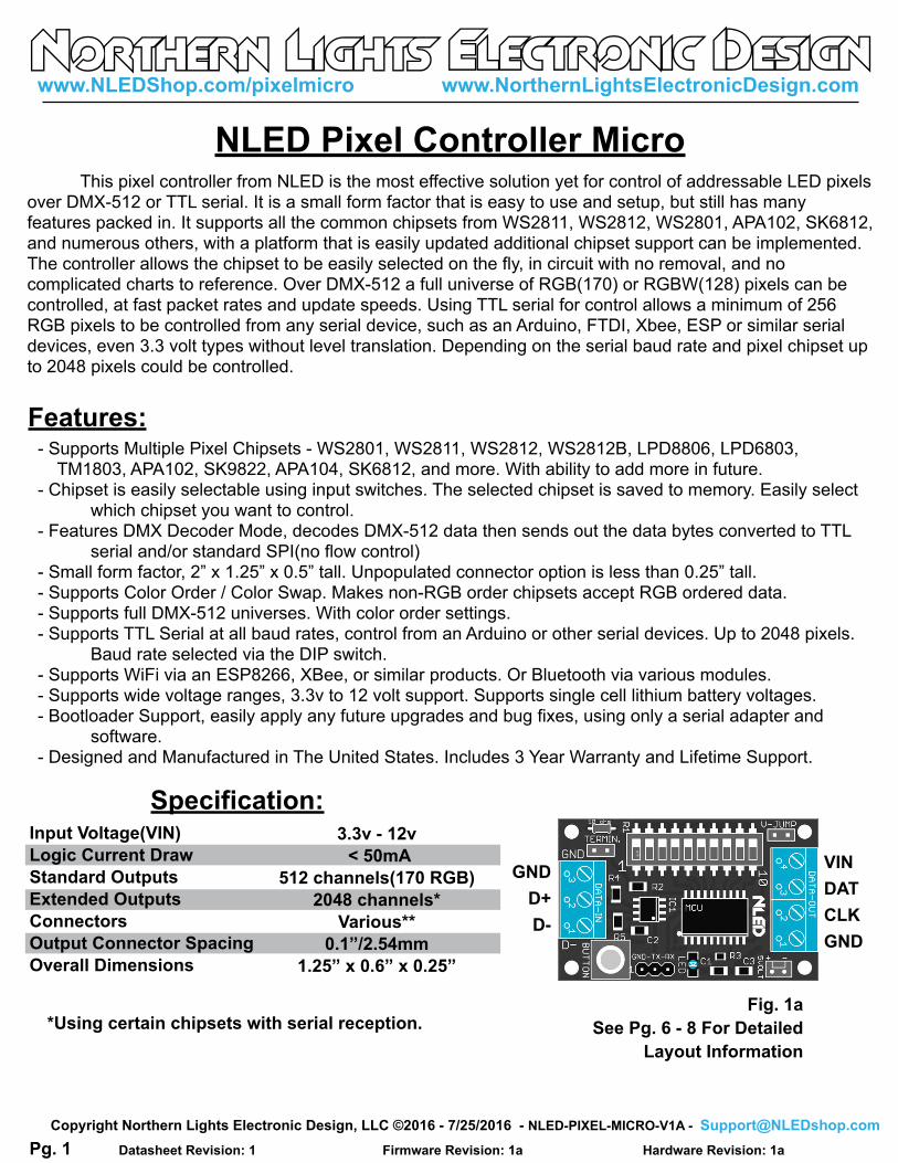
Specification:
*Using certain chipsets with serial reception.
Input Voltage(VIN)
Logic Current Draw
Standard Outputs
Extended Outputs
Connectors
Output Connector Spacing
Overall Dimensions
3.3v - 12v
< 50mA
512 channels(170 RGB)
2048 channels*
Various**
0.1”/2.54mm
1.25” x 0.6” x 0.25”
This pixel controller from NLED is the most effective solution yet for control of addressable LED pixels over DMX-512 or TTL serial. It is a small form factor that is easy to use and setup, but still has many features packed in. It supports all the common chipsets from WS2811, WS2812, WS2801, APA102, SK6812, and numerous others, with a platform that is easily updated additional chipset support can be implemented. The controller allows the chipset to be easily selected on the fly, in circuit with no removal, and no complicated charts to reference. Over DMX-512 a full universe of RGB(170) or RGBW(128) pixels can be controlled, at fast packet rates and update speeds. Using TTL serial for control allows a minimum of 256 RGB pixels to be controlled from any serial device, such as an Arduino, FTDI, Xbee, ESP or similar serial devices, even 3.3 volt types without level translation. Depending on the serial baud rate and pixel chipset up to 2048 pixels could be controlled.
Features:- Supports Multiple Pixel Chipsets - WS2801, WS2811, WS2812, WS2812B, LPD8806, LPD6803, TM1803, APA102, SK9822, APA104, SK6812, and more. With ability to add more in future.- Chipset is easily selectable using input switches. The selected chipset is saved to memory. Easily select which chipset you want to control.- Features DMX Decoder Mode, decodes DMX-512 data then sends out the data bytes converted to TTL serial and/or standard SPI(no flow control)- Small form factor, 2” x 1.25” x 0.5” tall. Unpopulated connector option is less than 0.25” tall.- Supports Color Order / Color Swap. Makes non-RGB order chipsets accept RGB ordered data.- Supports full DMX-512 universes. With color order settings.- Supports TTL Serial at all baud rates, control from an Arduino or other serial devices. Up to 2048 pixels. Baud rate selected via the DIP switch.- Supports WiFi via an ESP8266, XBee, or similar products. Or Bluetooth via various modules.- Supports wide voltage ranges, 3.3v to 12 volt support. Supports single cell lithium battery voltages.- Bootloader Support, easily apply any future upgrades and bug fixes, using only a serial adapter and software.- Designed and Manufactured in The United States. Includes 3 Year Warranty and Lifetime Support.
NLED Pixel Controller Micro
VIN
DAT
CLK
GND
Fig. 1a
See Pg. 6 - 8 For Detailed
Layout Information
GND
D+
D-
Pg. 1
www.NLEDShop.com/pixelmicro www.NorthernLightsElectronicDesign.com
Datasheet Revision: 1 Hardware Revision: 1a Firmware Revision: 1a
Copyright Northern Lights Electronic Design, LLC ©2016 - 7/25/2016 - NLED-PIXEL-MICRO-V1A - [email protected]
Want Another Pixel Chipset Supported? Contact [email protected] for To Request It
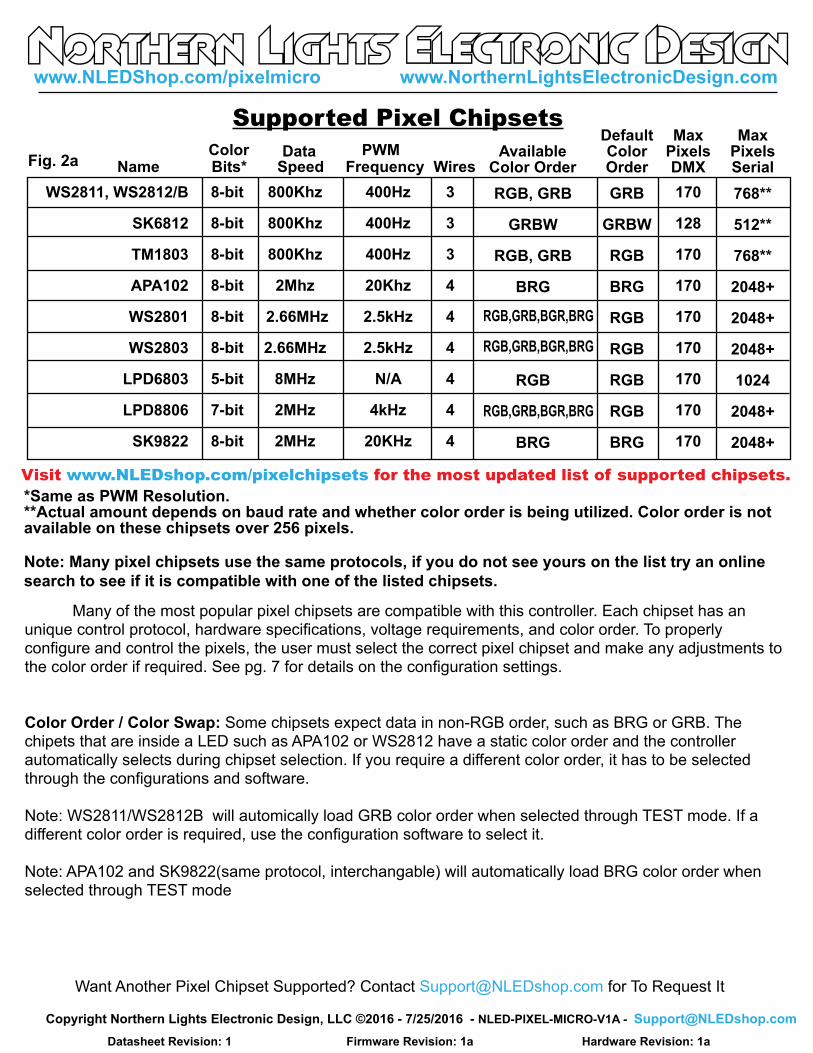
Supported Pixel Chipsets
Many of the most popular pixel chipsets are compatible with this controller. Each chipset has an unique control protocol, hardware specifications, voltage requirements, and color order. To properly configure and control the pixels, the user must select the correct pixel chipset and make any adjustments to the color order if required. See pg. 7 for details on the configuration settings.
Color Order / Color Swap: Some chipsets expect data in non-RGB order, such as BRG or GRB. The chipets that are inside a LED such as APA102 or WS2812 have a static color order and the controller automatically selects during chipset selection. If you require a different color order, it has to be selected through the configurations and software.
Note: WS2811/WS2812B will automically load GRB color order when selected through TEST mode. If a different color order is required, use the configuration software to select it.
Note: APA102 and SK9822(same protocol, interchangable) will automatically load BRG color order when selected through TEST mode
Fig. 2a
WS2811, WS2812/B
SK6812
TM1803
APA102
WS2801
WS2803
LPD6803
LPD8806
SK9822
8-bit
8-bit
8-bit
8-bit
8-bit
8-bit
5-bit
7-bit
8-bit
800Khz
800Khz
800Khz
2Mhz
2.66MHz
2.66MHz
8MHz
2MHz
2MHz
Name Bits* Speed Frequency
400Hz
400Hz
400Hz
20Khz
2.5kHz
2.5kHz
N/A
4kHz
20KHz
Visit www.NLEDshop.com/pixelchipsets for the most updated list of supported chipsets.
Color PWM
*Same as PWM Resolution.**Actual amount depends on baud rate and whether color order is being utilized. Color order is notavailable on these chipsets over 256 pixels.
AvailableColor Order
RGB, GRB
GRBW
RGB, GRB
BRG
RGB
BRG
Wires
3
3
3
4
4
4
4
4
4
DefaultColorOrder
GRB
GRBW
RGB
BRG
RGB
RGB
RGB
RGB
BRG
MaxPixelsDMX
170
128
170
170
170
170
170
170
170
768**
512**
768**
2048+
2048+
2048+
1024
2048+
2048+
MaxPixelsSerial
RGB,GRB,BGR,BRG
RGB,GRB,BGR,BRG
RGB,GRB,BGR,BRG
Data
Note: Many pixel chipsets use the same protocols, if you do not see yours on the list try an online
search to see if it is compatible with one of the listed chipsets.
www.NLEDShop.com/pixelmicro www.NorthernLightsElectronicDesign.com
Datasheet Revision: 1 Hardware Revision: 1a Firmware Revision: 1a
Copyright Northern Lights Electronic Design, LLC ©2016 - 7/25/2016 - NLED-PIXEL-MICRO-V1A - [email protected]
ON
1 2 3 4 5 6 7 8 9 10
ON
1 2 3 4 5 6 7 8 9 10
ON
1 2 3 4 5 6 7 8 9 10
ON
1 2 3 4 5 6 7 8 9 10
ON
1 2 3 4 5 6 7 8 9 10
ON
1 2 3 4 5 6 7 8 9 10
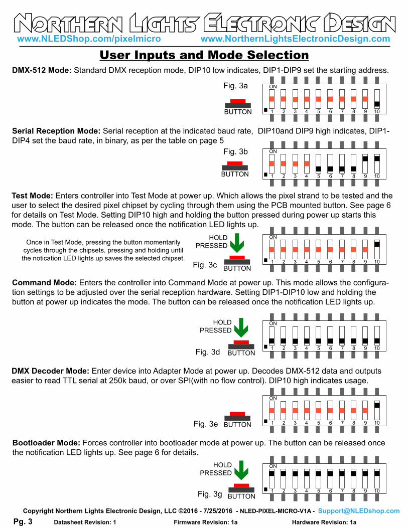
DMX-512 Mode: Standard DMX reception mode, DIP10 low indicates, DIP1-DIP9 set the starting address.
Serial Reception Mode: Serial reception at the indicated baud rate, DIP10and DIP9 high indicates, DIP1-
DIP4 set the baud rate, in binary, as per the table on page 5
Test Mode: Enters controller into Test Mode at power up. Which allows the pixel strand to be tested and the
user to select the desired pixel chipset by cycling through them using the PCB mounted button. See page 6
for details on Test Mode. Setting DIP10 high and holding the button pressed during power up starts this
mode. The button can be released once the notification LED lights up.
Command Mode: Enters the controller into Command Mode at power up. This mode allows the configura-
tion settings to be adjusted over the serial reception hardware. Setting DIP1-DIP10 low and holding the
button at power up indicates the mode. The button can be released once the notification LED lights up.
DMX Decoder Mode: Enter device into Adapter Mode at power up. Decodes DMX-512 data and outputs
easier to read TTL serial at 250k baud, or over SPI(with no flow control). DIP10 high indicates usage.
Bootloader Mode: Forces controller into bootloader mode at power up. The button can be released once
the notification LED lights up. See page 6 for details.
BUTTON
HOLD
PRESSED
BUTTON
HOLD
PRESSED
BUTTON
HOLD
PRESSED
BUTTON
BUTTON
BUTTON
Once in Test Mode, pressing the button momentarily
cycles through the chipsets, pressing and holding until
the notication LED lights up saves the selected chipset.
User Inputs and Mode Selection
Fig. 3a
Fig. 3b
Fig. 3c
Fig. 3d
Fig. 3e
Fig. 3g
Pg. 3
www.NLEDShop.com/pixelmicro www.NorthernLightsElectronicDesign.com
Datasheet Revision: 1 Hardware Revision: 1a Firmware Revision: 1a
Copyright Northern Lights Electronic Design, LLC ©2016 - 7/25/2016 - NLED-PIXEL-MICRO-V1A - [email protected]

DMX-512 Usage
1.....512
0 - 255
0 - 255
512 Channel Mode, 8-bit: Standard Direct Control
Need something different? Custom? Contact [email protected] for Help
Channel Value Description
0 is 0%, 255 is 100%
0 is 0%, 255 is 100%
DMX Decoder Mode
This mode allows a DMX-512 universe to be decoded into a standard serial data or SPI data, suitable
for other devices, such as Arduinos, FTDI etc. The amount of channels it decodes and sends out can be set
in the configurations. The starting address of collection is indicated by DIP1-DIP8(DIP9 with configuration).
To indicate to the controller to enter into this mode DIP10 and DIP 9 are set high. But due to the entry
method using DIP9, the starting address can not utilize DIP9 unless the configuration “Force Decoder Mode”
is set through software. Once that configuration is enabled, it disables Serial Mode, and will enter DMX
Decoder Mode when DIP10 is set high and the button is not pressed at power up. This allows DIP9 to be
used for addressing.
The User Pixel Amount configuration is used to set how many channels of data the controller should
send out, from 1 - 255 bytes. If decoding full DMX-512 universe is required the configuration “Force Full
Packets” can be enabled, the controller will then send all channels available, starting at the indicated start
address. Note: If starting at address 1, 512 bytes would be transmitted, if starting address is 400, 112 bytes
would be collected and transmitted.
ON
1 2 3 4 5 6 7 8 9 10
1 2 4 8 16 32 64 128 256 Binary Value:
Binary Notes All numbers such as the DMX starting address and serial baud rate ID, are indicated using the DIP
switches and binary numbers. The DIP switches indicate a binary place, doubling each position it goes up.
The places are added together to make the final number. Note: Places are LSB on the left, MSB on the right.
Which is how humans read it, but not computers, some binary converters will output right to left.
Online there are many “DMX DIP Switch Calculators” to help in converting the numbers.
Example #83: 1100-1010-0
Example #318: 0111-1100-1
Fig. 4a
Pg. 4
www.NLEDShop.com/pixelmicro www.NorthernLightsElectronicDesign.com
Datasheet Revision: 1 Hardware Revision: 1a Firmware Revision: 1a
Copyright Northern Lights Electronic Design, LLC ©2016 - 7/25/2016 - NLED-PIXEL-MICRO-V1A - [email protected]

Serial Reception Usage
1
2
3
RX TX
TX RX
GND GND
RX-TX-GND Header
Connection
Fig. 5b
Device:
Serial reception can directly control the device’s outputs using a common serial transmission device. Such as a standard COM port with level translation, an FTDI adapter, Arduino, PIC UART, wireless XBee, or similar. The device receives data in packets, the size(in bytes) of the packet corresponds to how many channels will be controlled. Example: Sending a packet of 90 bytes will control 30 RGB pixels, sending 510 bytes would control 170 RGB pixels. There is a maximum of 1mS between bytes and a minimum of 1mS between packets(end-of-frame), to allow the data to latch. A delay between received data bytes of more than 1mS will reset the buffer pointer, framing the data. Partial packets will latch after the 1mS delay, or latching will occur immediately after receiving the last byte(if configured). The baud rate is selected at power up via the DIP switches, when serial mode is indicated(DIP10 and DIP9 set).The byte formatting is the standard 8-N-1(8-bits, no parity, 1 stop bit) Depending on the chipset and any user selected color orders, the controller may expect data in non-RGB orders. See Page 2 regarding color order and see page 7 for information on selecting a color order. By default, serial reception will not do any color re-ordering, and should be done before transmitting. Enabling color order will slow down reception and may limit the maximum number of pixels that can be controlled.
123 Fig. 4c
Controller RX supports both 3.3 volt and 5 volt
logic levels, TX outputs at 5 volt logic level.
Level translation is not required.
Command Mode
*Note: Percentage of error is within usable limits.
And won’t affect usage.
9,600
19,200
38,400
57,600
115,200
230,400
460,800
921,600
9,615
19,230
38,461
57,142
117,647
222,222
250,000
444,444
500,000
1,000,000
0.16%
0.16%
0.16%
0.64%
-0.79%
2.12%*
-3.55%*
8.51%
Closest
Common
Baud Rate
Actual
Device
Baud Error %
Fig. 5a
ID#
0
1
2
3
4
5
6
7
8
9
8-N-1
“Actual Device Baud” is the exact rate
the controller is expecting, match it for a
0% error value.
DIP Sw.
(LSB....MSB)
0000000011
1000000011
0100000011
1100000011
001000011
1010000011
011000011
111000011
000100011
100100011
Command mode allows the configurations to be adjusted via a USB to serial adapter over the TTL serial header GND-TX-RX. See user inputs in how to enter the device into Command Mode.
For configuring not through the software, the protocol is simple. The baud rate is 19,200 at 8-N-1. Once entered into command mode, send the data as numbers, the LED will toggle states with each byte. Do as follows:Send as numbers: 123 -> 253 -> 82 -> 7That unlocks locks the function and frames the data.Then Send the configuration bytes, as numbers: Chipset ID# -> User Pixel Amount -> ConfigFlagsOnce it has received those 7 bytes, it will start to blink steadily, power off the controller, set your DIP switches, and power the controller back up. Note: See configurations page for byte info.
Pg. 5
www.NLEDShop.com/pixelmicro www.NorthernLightsElectronicDesign.com
Datasheet Revision: 1 Hardware Revision: 1a Firmware Revision: 1a
Copyright Northern Lights Electronic Design, LLC ©2016 - 7/25/2016 - NLED-PIXEL-MICRO-V1A - [email protected]

This device includes a bootloader feature. It allows the firmware on the device to be upgraded with new features and bug fixes using only a common serial adapter and a small computer program.
After the device is connected, please follow the instructions found at www.NLEDshop.com/bootloader. That is also where the software download links can be found. Note: This device uses the Serial Bootloader not the USB/HID Bootloader.
Firmware Updates Using The Bootloader
Firmware updates are encrypted and protected with special code that prevents other devices from being programmed with the update firmware images. And prevents non-NLED firmwares from being programmed onto the devices. If a firmware image is loaded onto a microcontroller without the special protection code it will respond to commands and USB will work, but the outputs will be off . Contact Us for help restoring your device to original condition if your microcontroller was damaged, erased, ‘bricked’, or otherwise not working correctly.
Fig. 6a
The bootloader entry method is: - With the device powered off, set all DIP switches high.- Connect your serial adapter to the controller’s GND-TX-RX header. Ensure RX->TX, TX->RX- Power up the device while holding the button pressed. - Wait a second or two and release the button. The device’s notification LED should start blinking.- Start the software and set it up using the instructions.- Load the correct HEX file, and follow the instructions to start the upload.- Wait til the upload is finished and the software notifies that it is done.- Power off the controller.- Set the DIP switches to desired mode. - Bootloader procedure complete.
ON
1 2 3 4 5 6 7 8 9 10BUTTON
HOLD
PRESSED
Test Mode Details
Test mode allows the pixel strand to be tested and to select the pixel chipset. In Test Mode it will attempt to control 1024 RGB pixels or 768 RGBW pixels. The Test Mode pattern is as follows:Off->Red->Yellow->Green->Teal->Blue->Purple-> Repeat
While in Test Mode, pressing the button cycles through the available pixel chipsets. With pixels connected, the user can cycle through the chipsets and once the correct one is selected, the LEDs will respond correctly. When the wrong chipset is selected the LEDs will do nothing, act erratically or otherwise not respond correctly.
Once the chipset is selected, the user pushes and holds the button until the notification LED turns on. When the LED turns on it indicates that the chipset ID has been saved to memory and the controller will use load it next time it powers up. Releasing the button will continue the test pattern.
Pg. 6
www.NLEDShop.com/pixelmicro www.NorthernLightsElectronicDesign.com
Datasheet Revision: 1 Hardware Revision: 1a Firmware Revision: 1a
Copyright Northern Lights Electronic Design, LLC ©2016 - 7/25/2016 - NLED-PIXEL-MICRO-V1A - [email protected]

Some of the configuration settings on this controller can only be accessed through software, and/or through Command Mode(detailed on page 5)Please visit the controller’s webpage to find the link to the current version of the configuration software or use the Command Mode information here to send the configuration settings from a serial terminal.
Device Configurations Settings
Select Correct RGB Order for Pixels: The different pixel chipsets require data to be received in various orders. Not all pixels will expect data in RGB order. It may expect GRB, BRG, or any combination, it varies chipset to chipset. This configuration setting allows the user to select the correct color order for their pixels. Note on this controller not all color order options are available.
Select The Pixel Chipset Being Used: The most important configuration setting, this option must be the same as the pixels you expect to utilize. See pg. 2 for compatibility list.
Indicator LED Mode: Enables or disables the notification LED usage. If disabled the LED will not turn on.
DMX Decoder Mode, Force Full Packets: This setting allows up to a full universe of data to be converted from DMX-512 to TTL serial. When disabled, the controller will collect and send only the an amount of bytes equal to the User Pixel Amount configuration.
Force Decoder Mode: Forces Decoder Mode when DIP10 is set, ignoring serial mode. When enabled it allows the starting address for Decoder Mode to use DIP9 for addressing. Otherwise if DIP10 and DIP9 are set it would enter Serial mode when powered up. With this configuration enabled, it can not enter serial mode.
Enable Serial Color Swap: When disabled, and in serial mode all data is received and transmitted in RGB order, it is fastest to have it disabled but any color ordering has to be done on transmitter side. When enabled it will try and use the color order as selected in the configurations. Not all chipsets have the function available.
User Pixel Amount: Configures how many pixels the DMX routine should collect data for, default is 170 RGB pixels, which equates to 510 DMX channels. If a RGBW chipset is selected, it would instead collect data for 128 pixels which would be 512 channels. Most users can leave this at 170. But for better performance with fast packet rates or partial packets, this value could be lowered to match the amount of pixels that will be controlled.
See Page 5, for details on using Command Mode
Chipset ID#:0 - WS2811/WS2812/SK68122 - WS28014 - LPD88066 - LPD68038 - APA102
User Pixel Amount: 1 - 255
Configuration Byte Bit Order(ConfigFlags):LSB - Bit0 - Indicator LED Enable Bit1 - DMX Decoder, Force Full Packets Bit2 - Enable Serial Color Swap Bit3 - GRB Color Order Bit4 - GRBW Color Order Bit5 - BGR Color Order Bit6 - BRG Color OrderMSB - Bit7 - Force Decoder Mode
Note: Do not set more than one color order at a time.Default ConfigFlags is 0x01, 00000001
Pg. 7
www.NLEDShop.com/pixelmicro www.NorthernLightsElectronicDesign.com
Datasheet Revision: 1 Hardware Revision: 1a Firmware Revision: 1a
Copyright Northern Lights Electronic Design, LLC ©2016 - 7/25/2016 - NLED-PIXEL-MICRO-V1A - [email protected]
+5v
DAT
CLK
GND
+5v
DAT
CLK
GND
+5v
DAT
GND
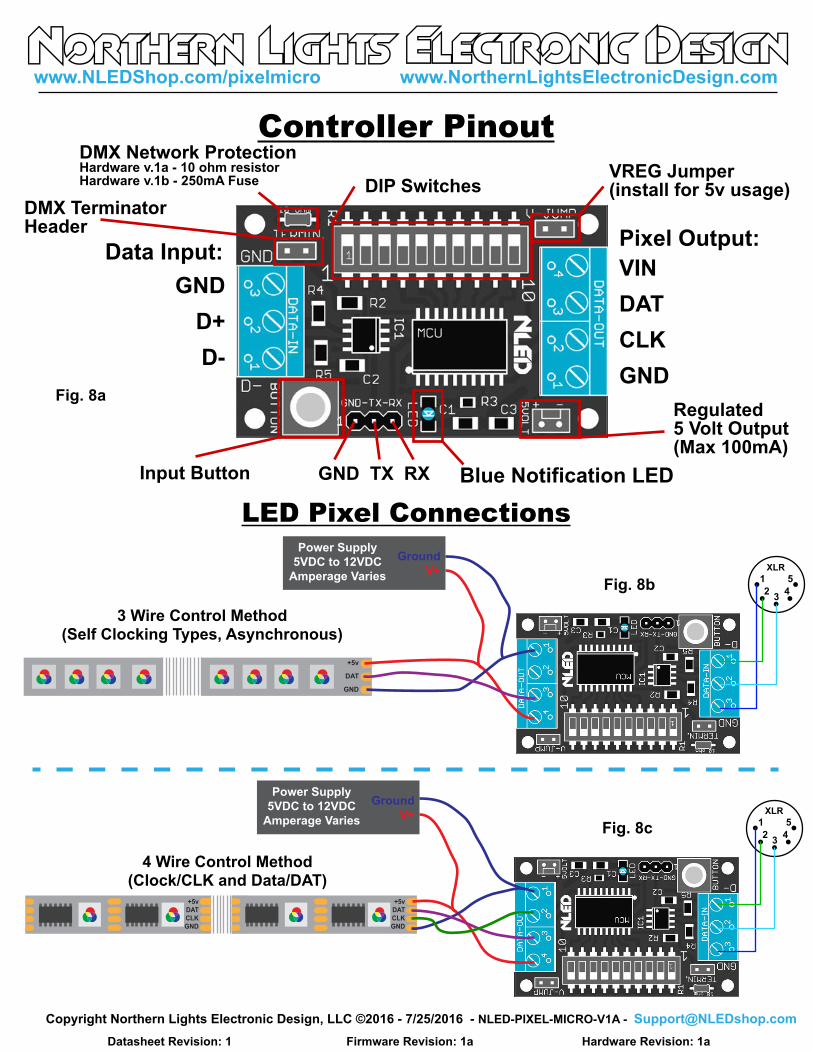
3 Wire Control Method(Self Clocking Types, Asynchronous)
4 Wire Control Method(Clock/CLK and Data/DAT)
Fig. 8b
XLR
Ground
V+
Power Supply
5VDC to 12VDC
Amperage Varies
Ground
V+
Power Supply
5VDC to 12VDC
Amperage Varies
LED Pixel Connections
XLR
Fig. 8c
Controller Pinout
Blue Notification LED
VIN
DAT
CLK
GND
GND
D+
D-
Pixel Output:Data Input:
GND TX RX
DMX TerminatorHeader
DMX Network ProtectionHardware v.1a - 10 ohm resistorHardware v.1b - 250mA Fuse
VREG Jumper(install for 5v usage)
Input Button
Regulated5 Volt Output(Max 100mA)
DIP Switches
Fig. 8a
www.NLEDShop.com/pixelmicro www.NorthernLightsElectronicDesign.com
Datasheet Revision: 1 Hardware Revision: 1a Firmware Revision: 1a
Copyright Northern Lights Electronic Design, LLC ©2016 - 7/25/2016 - NLED-PIXEL-MICRO-V1A - [email protected]

The controller only draws less than 100mA, the bulk of the current is consumed by the LED pixels. Each pixel can draw up to 60mA each at full intensity.
Example: 170 pixels at 60mA each: 170 x 0.06 = 10.2 Amps potential maximum draw.
The standard voltage for LED pixels is 5 volts, but 12 volt types are also available. The V-JUMP position on the controller is used for setting up either 5 volt use, which requires installing a jumper wire in the V-JUMP position. Or if the controller will operate on an input votlage larger than 5 volts, the V-JUMP position is left open.
Power Considerations
Serial Data Connections
TERMIN: Header for DMX terminator, only install the jumper if the controller is the only or last device on the DMX network. Terminating is a technical consideration, specific information can be found online.
The controller is a 5 volt device, but can receive(RX) from 3.3 volt signals, but transmits(TX) at 5 volts levels. Either TTL serial or RS485 serial can be used to transmit data to the controller, connect your transmitter to the one you would like to use.
TTL (5 volt levels)
Serial Device
OR
RS485(differential)
Serial Transmitter
(or DMX-512)
TERMIN.
GND
D+
D-
GNDRXTX
V-JUMP
External Device/Module
5 volt, max 100mA draw
Ground/V-
+5 volts
Fig. 9a
Fig. 9b
Pg. 9
www.NLEDShop.com/pixelmicro www.NorthernLightsElectronicDesign.com
Datasheet Revision: 1 Hardware Revision: 1a Firmware Revision: 1a
Copyright Northern Lights Electronic Design, LLC ©2016 - 7/25/2016 - NLED-PIXEL-MICRO-V1A - [email protected]
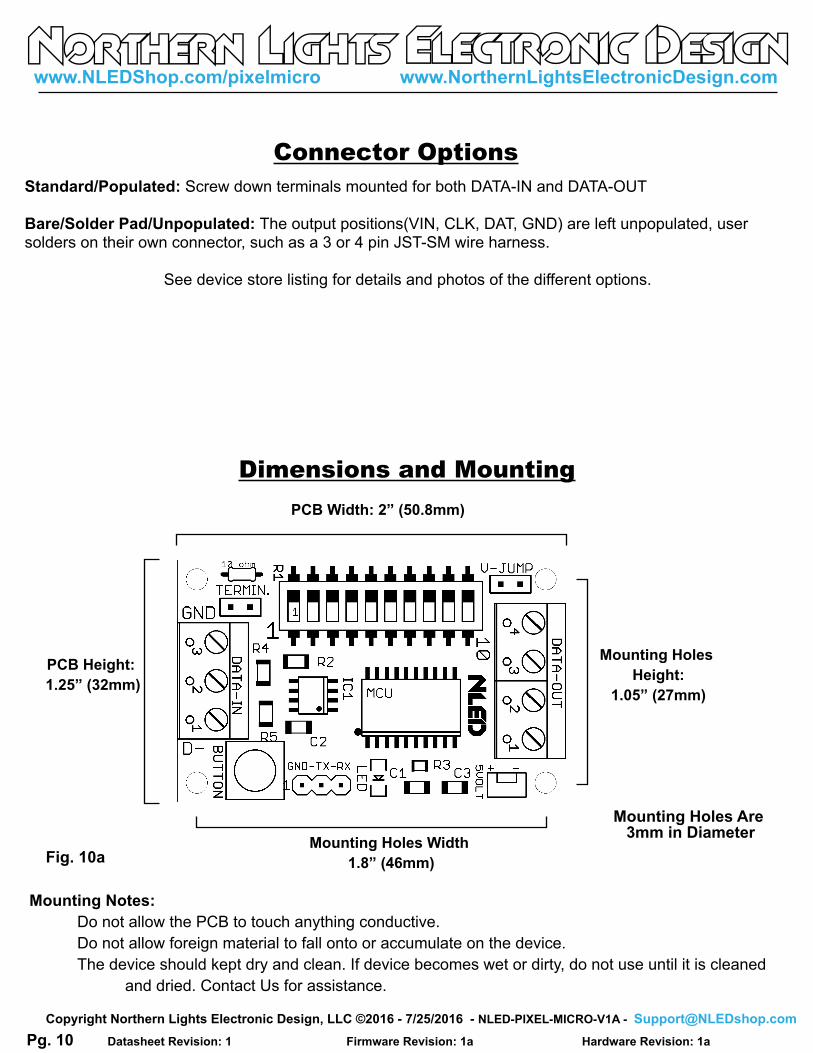
Mounting Notes:
Do not allow the PCB to touch anything conductive.
Do not allow foreign material to fall onto or accumulate on the device.
The device should kept dry and clean. If device becomes wet or dirty, do not use until it is cleaned
and dried. Contact Us for assistance.
Dimensions and Mounting
Fig. 10a
Connector Options
Standard/Populated: Screw down terminals mounted for both DATA-IN and DATA-OUT
Bare/Solder Pad/Unpopulated: The output positions(VIN, CLK, DAT, GND) are left unpopulated, user solders on their own connector, such as a 3 or 4 pin JST-SM wire harness.
See device store listing for details and photos of the different options.
PCB Height:
1.25” (32mm)
Mounting Holes
Height:
1.05” (27mm)
Mounting Holes Width
1.8” (46mm)
PCB Width: 2” (50.8mm)
Mounting Holes Are 3mm in Diameter
Pg. 10
www.NLEDShop.com/pixelmicro www.NorthernLightsElectronicDesign.com
Datasheet Revision: 1 Hardware Revision: 1a Firmware Revision: 1a
Copyright Northern Lights Electronic Design, LLC ©2016 - 7/25/2016 - NLED-PIXEL-MICRO-V1A - [email protected]
Setup:1. Decide if you will need to install the V-JUMP. If your pixel voltage is 5 volts, install a jumper in V-JUMP. If your pixels/power supply is greater than 12 volts DO NOT INSTALL V-JUMP, leave open.2. If the pixel chipset and/or any other configurations need to be configured, follow the instructions on page 2 and 3 for details on connecting to software.3. For testing purposes, it is recommended that Test Mode be ran first as described below before attempting data control to ensure your pixels are connected properly.
DMX Usage:1. With the power off, set DIP10 low, and set DIP1-DIP9 with the starting DMX address.2. If the controller will be the only device on the network, install the jumper on the pin header TERMIN. This terminates the DMX signal preventing interference(reflections)3. Connect to the DMX network using the 3-position terminal, GND, D+, D- . A 3-pin or 5-pin XLR is commonly used.4. Power up the controller.5. The controller should start receiving the DMX data starting at the configured DMX Address. The notification LED will flash indicating the controller is receiving valid DMX data. The flash speed indicates packet rate.
Serial Control Usage:1. With the power off. Set DIP10 high, and set DIP1-DIP5 to the baud rate ID number in binary.2. If using TTL serial, connect your serial adapter to GND and RX(that is TX from the adapter to RX on the controller.) Note TX on the controller side is only used for DMX Adapter Mode.2. If using differential(RS485) connect the transmitter to the controller’s DATA-IN terminal via GND, D-, D+3. Power up the controller.4. Start transmission from transmitting serial device, at the configured baud rate.5. The notification LED will blink indicating it has latched a data packet Once data has been sent.
Testing The Controller and Setting The Chipset:1. Disconnect Power.2. Set DIP10 to high. Other DIP switches can be in any state.3. Power up the controller while holding down the button.4. After it powers up the notification LED will turn on. and start to blink slowly. At about 2hz.5. If it does not ensure the controller is getting suitable power as and V-JUMP has been configured.6. Connect the pixel strand and power it up.7. Press the button and release to change to the next pixel chipset, if it blinks/strobes/erratic, keep pressing til the pattern is Off-Red-Yellow-Green-Teal-Blue-Purple-White->repeat a. If it blinks/strobes erratically it may either DAT and CLK are swapped, or the chipset is not configured does not match the chipset that is connected.8. Once the correct chipset has been selected using the button, and the color order is correct. Press and hold the button until the notification LED turns on, that indicates it has saved the chipset to memory.9. The controller is now ready to use. Power down the controller and set it up for whatever data mode is going to be used.
Controller Setup(Continued)
Pg. 11
www.NLEDShop.com/pixelmicro www.NorthernLightsElectronicDesign.com
Datasheet Revision: 1 Hardware Revision: 1a Firmware Revision: 1a
Copyright Northern Lights Electronic Design, LLC ©2016 - 7/25/2016 - NLED-PIXEL-MICRO-V1A - [email protected]
Common Issues and Troubleshooting
Please Contact [email protected] with any Questions, Comments, or Bug Reports.
Have Any Ideas for Future Updates Northern Lights Electronic Design, LLC is constantly looking to make our products better and improve
upon our designs. If you have any ideas for future products, updates to current products, or features that you
would find useful, please Contact Us at [email protected]. There is a good chance your ideas could
be utilized, you could also receive coupons or free items for your feedback.
NLED is available to create new designs and derivatives of current designs customized to the clients
requirements, please Contact Us with your specifications.
Controller Setup(Continued)
Most issues can be resolved by power off the device, waiting a few seconds, and powering it back up.
Problem: Device with connected LEDs does not produce any light.
First ensure the LEDs are properly powered and wired to the controller and power source. Try to cycle
through the Sequences or modes using the button. And ensure you have selected the correct pixel chipset.
Problem: Device connected, LEDs are strobing or not working
Ensure you have selected then uploaded the correct Pixel Chipset configuration setting. Double check CLK
and DAT aren’t switched(if applicable)
Problem: Device appears to be “bricked”, unresponsive to user inputs and/or communication
Attempt to upload a new firmware image via the Bootloader, see page xx for details.
DMX Decoder Mode:SETUP: By default it outputs 170 bytes/channels of DMX data when collected, using the software and configurations this number can be set from 1 - 255. If a whole universe is required, a configuration can be set through software to send out the whole universe(or up to). And if a starting address that requires DIP9 is needed there is another configuration setting that needs to be set through software.1. With the power off, set DIP10 and DIP9 high.(DIP9 may not need to be set, see configurations)2. Connect the receiving serial device to GND-TX-RX header, making sure to cross TX and RX. See page 5.Or if using SPI, connect your receiving SPI device to the DATA-OUT terminal. Via CLK and DAT.3. Set DIP1-DIP8 to the DMX starting address. If the configuration is set, DIP9 can also be used.4. Power up the controller and apply a DMX signal to be decoded.5. The controller should then start sending out the decoded DMX data over serial and SPI, the notification LED blinks to indicate a packet has been collected.
Pg. 12
www.NLEDShop.com/pixelmicro www.NorthernLightsElectronicDesign.com
Datasheet Revision: 1 Hardware Revision: 1a Firmware Revision: 1a
Copyright Northern Lights Electronic Design, LLC ©2016 - 7/25/2016 - NLED-PIXEL-MICRO-V1A - [email protected]