Embed Size (px)
Citation preview
NASA Reference Publication 1036
ALSEP Termination Report
James R. Bates, W. W. Lauderdale,
and Harold Kernaghan
APRIL 1979
N/LS/X
NASA Reference Publication 1036
ALSEP Termination Report
James R. Bates
Lyndon B. Johnson Space Center, Houston, Texas
W. W. Lauderdale
General Electric Company, Houston, Texas
Harold Kernaghan
Kentron International, Inc., Houston, Texas
NILSANational Aeronautics
and Space Administration
Scientific and Technical
Information Office
1979
FOREWORD
This report summarizes the Apollo Lunar Surface Experiments PackageIALSEP) operations and provides background information for studies in lunar
;cience. The report was prepared when the receipt of data from the lunariurface was terminated on September 30, 1977; it is intended as an overview
_f the ALSEP activities, and specific details relative to ALSEP scientific
iata are outside the scope of information presented here. The ALSEP data
_or scientific analysis requirements can be obtained from the National Space
;cience Data Center (NSSDC), Code 601.4, Goddard Space Flight Center, Green-_elt, Maryland 20771.
rDetails regarding the placing of ALSEP stations on the lunar surface
_ave been covered thoroughly in many publications; such information will not
_e presented here. Documentation on the ALSEP design, development, and oper-
are archived at the Lyndon B. Johnson Space Center and at other NASA
iii


CONTENTS
Section
1. INTRODUCTION.......................
ALSEPLOCATIONSANDSTARTTIMES..............
PROGRAMINFORMATIONSUMMARY................
ALSEPCONFIGURATIONS...................
2. ALSEPDESCRIPTION.....................
SYSTEMCHARACTERISTICS..................
Central Station .....................
Dust Detector ......................
Radioisotope Thermoelectric Generator ..........
EASEPPassive Seismic Experiment ............
Active Seismic Experiment ................
Lunar Seismic Profiling ..... .... , .......
Heat Flow Experiment ..................
Solar WindExperiment ..................
Suprathermal Ion Detector ................
Cold Cathode Ion Gage ..................
MagnetometerExperiment .................
ChargedParticle Experiment ...............
Passive Seismic Experiment ...............
Lunar Ejecta and Meteorites Experiment .........
Lunar MassSpectrometer .................
Lunar Surface Gravimeter ................
Page
I-1
1-1
1-4
1-5
2-1
2-1
2-1
2-1
2-3
2-3
2-4
2-4
2-4
2-6
2-6
2-7
2-7
2-7
2-8
2-8
2-8
2-9
\
-4
Section
SUBSYSTEMS OF CENTRAL STATION ...............
Structural/Thermal Subsystem ..............
Data Subsystem .....................
Electrical Power Subsystem ...............
3. DATA MANAGEMENT AND ALSEP OPERATION ............
TRACKING STATIONS .....................
ALSEP CONTROL TEAMS ....................
FLIGHT CONTROLLER PERSONNEL ................
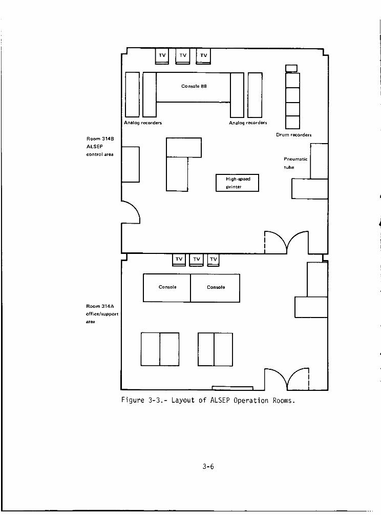
OPERATION ROOMS ......................
OPERATIONS PLANNING MEETINGS ...............
REFERENCE FILE ......................
ALSEP DATA ........................
Real-Time Data to JSC ..................
Experiment Data .....................
ARCHIVING .........................
NSSDC ARCHIVED DATA ............... .....
4. OPERATIONAL HISTORY ....................
PASSIVE SEISMIC EXPERIMENT ................
ACTIVE SEISMIC EXPERIMENT .................
LUNAR SURFACE MAGNETOMETER ................
SOLAR-WIND SPECTROMETER ..................
SUPRATHERMAL ION DETECTOR .................
HEAT FLOW EXPERIMENT .... . ..............
CHARGED PARTICLE LUNAR ENVIRONMENT EXPERIMENT .......
COLD CATHODE ION GAGE ...................
Page
2-9
2-9
2-12
2-16
3-1
3-1
3-1
3-5
3-5
3-7
3-7
3-7
3-7
3-8
3-12
3-13
4-1
4-2
4-7
4-9
4-13
4-15
4-19
4-20
4-22
vi

Section
LASERRANGINGRETROREFLECTORooooooooeooeooo
LUNAR EJECTA AND METEORITES EXPERIMENT ..........
LUNAR SEISMIC PROFILING EXPERIMENT ............
LUNAR ATMOSPHERIC COMPOSITION EXPERIMENT .........
LUNAR SURFACE GRAVIMETER .................
DUST DETECTOR EXPERIMENT .................
CENTRAL STATION ELECTRONICS ................
5. TERMINATION ANALYSIS (ENGINEERING CLOSEOUT TESTS) .....
STATUS OF EXPERIMENTS ...................
TEST CONSTRAINTS _ . ....................
ENGINEERING TESTS .....................
Apollo 12 ALSEP Tests ..................
Apollo 14 ALSEP Tests ..................
Apollo 15 ALSEP Tests ..................
Apollo 16 ALSEP Tests ..................
Apollo 17 ALSEP Tests ..................
OVERLOAD AND "RIPPLE OFF" TESTS ..............
Summary .........................
Discussion .......................
PSE-HEATER POWER TESTS ..................
Summary .........................
Discussion .......................
CENTRAL STATION COLD-TEMPERATURE TESTS ..........
Summary .........................
Discussion .......................
Page
4-24
4-25
4-26
4-27
4-29
4-31
4-32
5-1
5-1
5-2
5-3
5-3
5-4
5-5
5-6
5-6
5-7
5-7
5-8
5-9
5-9
5-10
5-11
5-11
5-12
i
vii

Section
CENTRAL STATION REDUNDANT COMPONENT TESTS .........
Summary .........................
Discussion .......................
TIMER "TIMEOUT" TESTS ...................
Summary .........................
Discussion .......................
COLD SOAKING THE LSM AND LSG EXPERIMENTS .........
Summary .........................
Discussion .......................
CANCELED TESTS ......................
CENTRAL STATION CONFIGURATION AT TERMINATIONOF ALSEP OPERATIONAL SUPPORT ..............
6. SIGNIFICANT ALSEP SCIENTIFIC RESULTS ...........
PASSlVE SEISMIC EXPERIMENT ................
Lunar Seismicity (By Gary V. Latham) ..........
Structure of the Moon (By Nafi Toks6z) .........
LUNAR NEAR-SURFACE STRUCTURE (ACTIVE SEISMIC) .......By Robert L. Kovach
LUNAR SURFACE MAGNETOMETERS ................
Lunar Electrical Conductivity and Structure .......(By Palmer Dya.1),
Apollo 12 and .15 Magnetometers (By C. P. Sonett) . . . .
SUPRATHERMAL ION DETECTOR EXPERIMENT ...........By John W. Freeman, Jr.
LUNAR HEAT FLOW EXPERIMENT ................By Marcus G. Langseth
CHARGED PARTICLE LUNAR ENVIRONMENT EXPERIMENT .......By David L. Reasoner
Page
5-12
5-13
5-13
5-14
5-14
5-14
5-14
5-14
5-15
5-15
5-17
6-1
6-2
6-2
6-3
6-4
6-5
6-5
6-10
6-12
viii
Section
COLDCATHODEGAGEEXPERIMENT...............By Francis S. Johnson
LUNARATMOSPHERICCOMPOSITIONEXPERIMENT.........By John H. Hoffman
LUNARSURFACEGRAVIMETEREXPERIMENT............By Joseph Weber
SOLARWINDSPECTROMETER..................By ConwayW. Snyder
LUNAREJECTAANDMETEORITES................By Otto E. Berg
7. SIGNIFICANTOPERATIONALDATA(INCREASINGTEMPERATURE). . .
8. RECOMMENDATIONS......................
9. BIBLIOGRAPHY.......................
APPENDIXA -- LIST OFACRONYMS..................
Page
6-14
6-14
6-15
6-15
6-16
7-1
8-1
9-1
A-1
ix
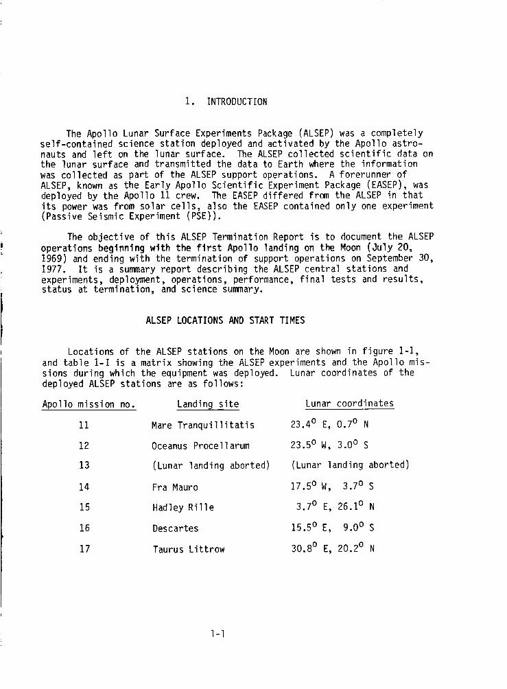
1. INTRODUCTION
The Apollo Lunar Surface Experiments Package (ALSEP) was a completelyself-contained science station deployed and activated by the Apollo astro-nauts and left on the lunar surface. The ALSEP collected scientific data onthe lunar surface and transmitted the data to Earth where the informationwas collected as part of the ALSEP support operations. A forerunner ofALSEP, known as the Early Apollo Scientific Experiment Package (EASEP), wasdeployed by the Apollo 11 crew. The EASEP differed from the ALSEP in thatits power was from solar cells, also the EASEP contained only one experiment(Passive Seismic Experiment (PSE)).
The objective of this ALSEP Termination Report is to document the ALSEPoperations beginning with the first Apollo landing on the Moon (July 20,1969) and ending with the termination of support operations on September 30,1977. It is a summary report describing the ALSEP central stations andexperiments, deployment, operations, performance, final tests and results,status at termination, and science summary.
ALSEP LOCATIONS AND START TIMES
Locations of the ALSEP stations on the Moon are shown in figure 1-1,and table 1-i is a matrix showing the ALSEP experiments and the Apollo mis-sions during which the equipment was deployed.deployed ALSEP stations are as follows:
Apollo mission no. Landing site
11 Mare Tranquillitatis
12 Oceanus Procellarum
13 (Lunar landing aborted)
14 Fra Mauro
15 Hadley Rille
16 Descartes
17 Taurus Littrow
Lunar coordinates of the
Lunar coordinates
23.4 o E, 0.7 o N
23.5 o W, 3.0 o S
(Lunar landing aborted)
17.5 o W, 3.7 o S
3.7 o E, 26.1 o N
15.5 o E, 9.0 o S
30.8 o E, 20.2 o N
I-I
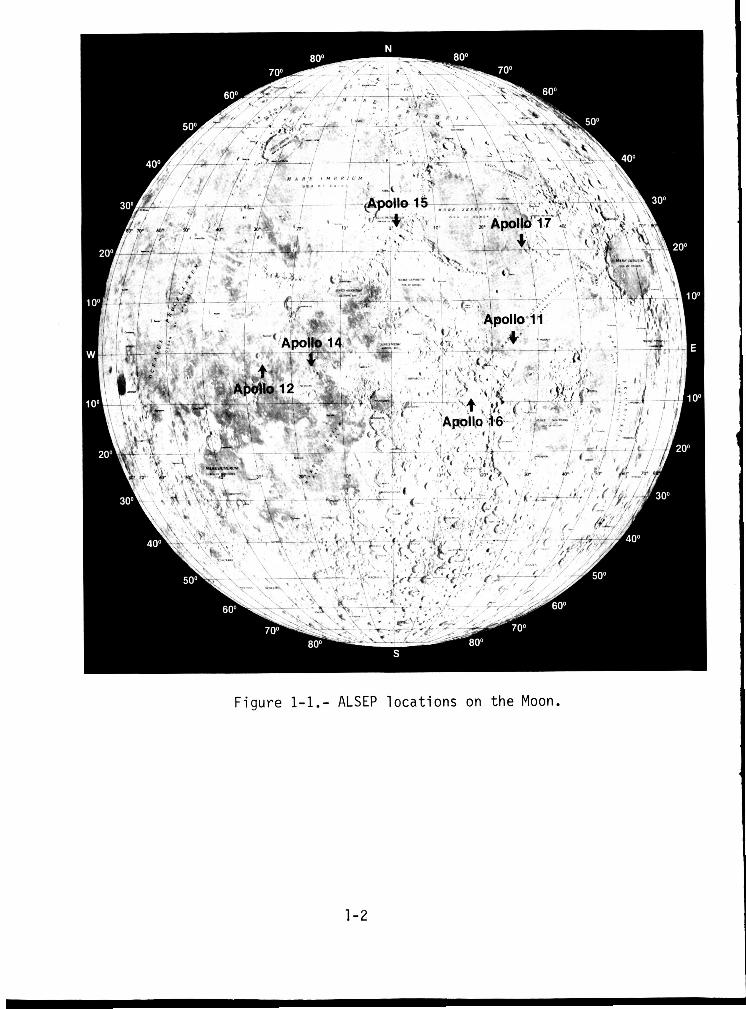
F i g u r e 1-1.- ALSEP l o c a t i o n s on t h e Moon.
1-2
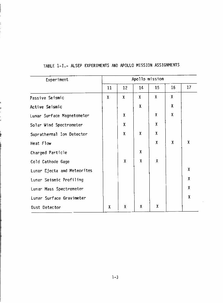
TABLE 1-I.- ALSEP EXPERIMENTS AND APOLLO MISSION ASSIGNMENTS
Experiment
Passive Seismic
Active Seismic
Lunar Surface Magnetometer
Solar Wind Spectrometer
Suprathermal lon Detector
Heat Flow
Charged Particle
Cold Cathode Gage
Lunar Ejecta and Meteorites
Lunar Seismic Profiling
Lunar Mass Spectrometer
Lunar Surface Gravimeter
Dust Detector
11
X
X
12
X
A_ollo mission
14 15
X X
X
X
X
X X
X
X
X X
X X
16
X
X
X
17
X
I-3

The dates and times (universal time (UT)) of initial downlink acquisitionfrom the ALSEP stations were as follows:
Apollo mission: Start date: Time, UT
11 July 21, 1969 04:41
12 Nov. 19, 1969 14:21
14 Feb. 5, 1971 17:23
15 July 31, 1971 18:37
16 Apr. 21, 1972 19:38
17 Dec. 12, 1972 02:53
PROGRAMINFORMATION SUMMARY
The program objectives were to acquire scientific data to aid indetermining
1. Internal structure and composition of the Moon
2. Composition of the lunar atmosphere
3. New insights into the geology and geophysics of Earth
4. State of the interior of the Moon
5. Genesis of lunar surface features
Program management was under the direction of the NASA Lyndon B.Johnson Space Center, Houston, Texas; the prime contractor was Bendix Aero-space Systems Division, Ann Arbor, Michigan. Major subcontractors wereA.D. Little, Bendix Electrodynamics, Bendix Research Labs, Bulova, Dyna-tronics, General Electric Valley Forge, Geotech, Gulton, Motorola, Philco-Ford, Space Ordnance Systems, Teledyne Earth Sciences, Time Zero, and Univer-sity of Texas at Dallas.
Principal Investigators for the various experiments were as follows:
Experiment
Passive Seismic Experiment
Apollo mission
Ii to 16
Principal Investigator
Gary LathamUniv. of Texas
Lunar Surface Magnetometer 12, 15, & 16 Palmer DyalAmes Research Center
Charles SonettUniv. of Arizona
I-4
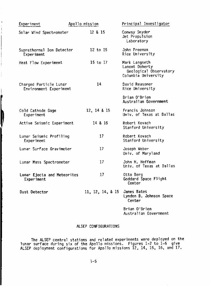
Experiment Apollo mission
Solar Wind Spectrometer 12 & 15
Suprathermal Ion DetectorExperiment
Heat Flow Experiment
12 to 15
15 to 17
Charged Particle LunarEnvironment Experiment
14
Cold Cathode GageExperiment
Active Seismic Experiment
12, 14 & 15
14 & 16
Lunar Seismic ProfilingExperiment
Lunar Surface Gravimeter
17
17
Lunar Mass Spectrometer 17
Lunar Ejecta and Meteorites
Experiment
17
Dust Detector Ii, 12, 14, & 15
Principal Investigator
Conway Snyder
Jet Propulsion
Laboratory
John Freeman
Rice University
Mark LangsethLamont Doherty
Geological ObservatoryColumbia University
David Reasoner
Rice University
Brian O'BrienAustralian Government
Francis JohnsonUniv. of Texas at Dallas
Robert Kovach
Stanford University
Robert Kovach
Stanford University
Joseph Weber
Univ. of Maryland
John H. HoffmanUniv. of Texas at Dallas
Otto BergGoddard Space Flight
Center
James Bates
Lyndon B. Johnson SpaceCenter
Brian O'Brien
Australian Government
ALSEP CONFIGURATIONS
The ALSEP central stations and related experiments were deployed on the
lunar surface during six of the Apollo missions. Figures 1-2 to 1-6 give
ALSEP deployment configurations for Apollo missions 12, 14, 15, 16, and 17.
I-5
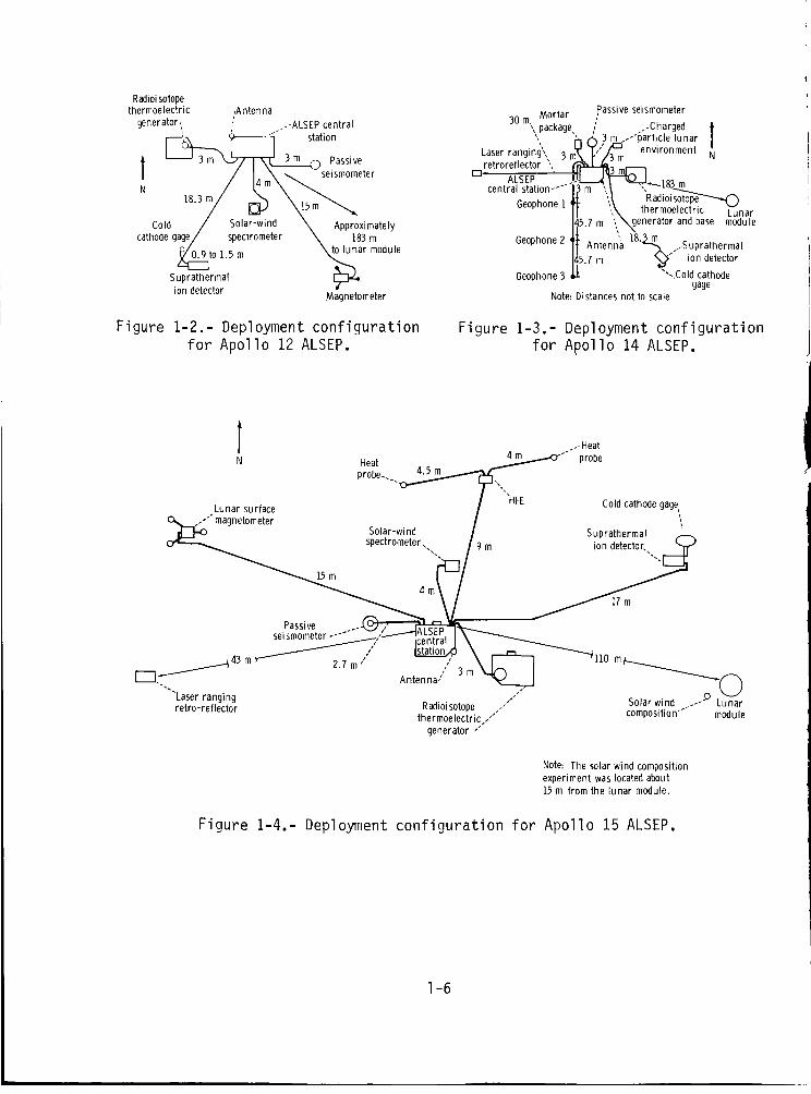
Radioisotopethermoelectric ,Antenna
generator, / ..-ALSEP central
t----i ,,at,onf _ 3 m _ Passive
IN / L'mX_ se'sm°meter
Cold / bola)'-wme X Approximatelycathode gage/ spectrometer \ 183 m
_]to I..5 m to_ar module
u erto a'Magnetometer
30 m, Mortar
,,package,.
Laser ranging',, 3retroreflector ",
rl,ALSEP
central station .....
Geophone 1
Passive seismometer
Oeophone 2
Oeophone 3
tt Antenna
5.7m
.-Charged3m..</'particle lunar l
environment N
_183 m
",_ "Radioi_',\ thermoelectric Lunar
',_generator__ and base module', 18.3 m
/Suprathermalion detector
"'..Cold cathodegage
Note: Distances not to scale
Figure 1-2.- Deployment configuration Figure 1-3.- Deployment configurationfor Apollo 12 ALSEP, for Apollo 14 ALSEP.
l .- Heat
4 m _.,c_" probeN Heat / v
probe.. _.
Cold cathode gage"'FIFE
Lunar surface _ _
O_ //magnetometer . . I .... ,,Solar-wind l 3upramermal
spectrometer. 9 m ion detector.
Passive . .I,,_ , ^, _r.
r-n-j " Antenna,""'Laser ranging ,," p v
.." Solar wind 1 Lunarretro-reflector Radioisotope . composition'" module
thermoelectric..'"generator /
Note: The solar wind composition
experiment was located about15 m from the lunar module.
Figure 1-4.- Deployment configuration for Apollo 15 ALSEP.
I-6
Grenade firing direction
?/^ . _ "---..., 4Lm ""-.,.Position lt_eopnone _ _ _ _'-.,_ Active sei stoic
Active__ J __ _'-_._., mortar._package
experiment thumper _',,,_e_,,_ Fiagl anchor/ _ /
Position ll_ _ Flag/anchor / 17 m
_ P°siti°n 17
, _nerato,........r.: 3 / ...._5_,v....¢
Lunar surface
magnetometer
15 ra
ALSEP / _ Passive• 3 m _)seismometer
central station"
Probe 1O"" Heat flowexperiment
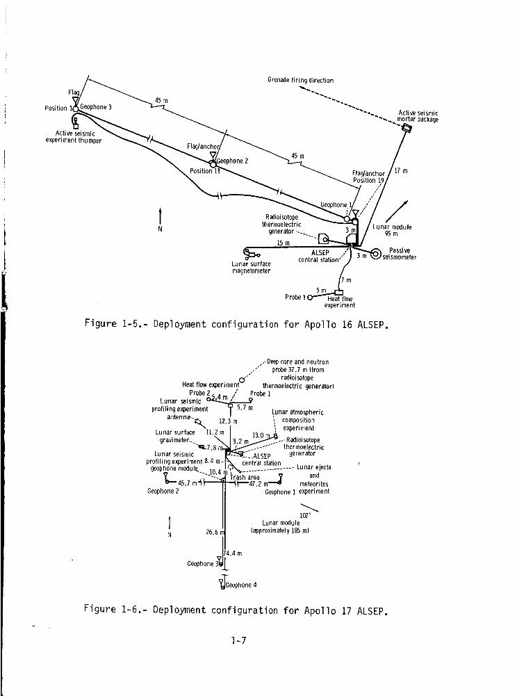
Figure 1-5.- Deployment configuration for Apollo 16 ALSEP.
/. Deepcore and neutron.-" probe 37.? m (from/
Heat flow experiment U"radioi sotope
thermoelectric generator)Probe 2.. / Probe 1
• . ,_.4m / m,Lunar se_smtc
profiling experiment ? 5.7 m Lunar atmosphericantenna-.._ 12.3 m composition
experiment
Lunar surface 11.2 m _, 13.0j_._ .Radioisotopegravimeter-. _, _ L m _ .... "
"- ,_ .... "" thermoelectricLunar seismic _L7.8 m- --_---':_ALSEP generator
profiling experiment 8.4 m-. _, central station
geophone module.... 10.4 ',"%- .......... Lunar ejecta
L45.7 m'_ Trash area '_' and"_-"-47.2 m_ meteorites
Geophone 2 Geophone 1 experiment
107°
I Lunar moduleN 26.6 _approximately I_5 m)
4.4m
Geophone _ _L
_TGeophone 4
Figure 1-6.- Deployment configuration for Apollo 17 ALSEP.
I-7
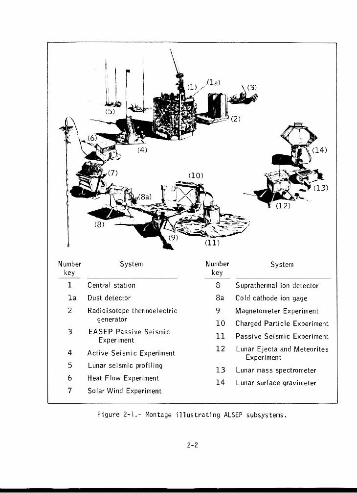
2. ALSEP DESCRIPTION
All the Apollo Lunar Surface Experiments Packages (ALSEP's) and repre-
sentative subsystems that were deployed during the six lunar landings areshown as a montage of illustrations in figure 2-1. Each item is identified
by a "number key" in parentheses and is described in the following paragraphs.
SYSTEM CHARACTERISTICS
Central Station (1)
The central station was the heart of ALSEP; it provided the radio
frequency (RF) link to Earth for telemetering data, for command and con-
trol, and for power distribution to the experiments. (For a more detaileddiscussion of the central station, see the subsection entitled "Subsystems
of Central Station.")
Mass, kg ................................. 25
Stowed volume, cm3 ....................... 34 800
Total power, W .......................... • 73
Average data rate, bits/sec .............. 33.1
Performance data: Transmits with 1W between 2275 and 2280 MHz at 530,
1060, 3533, or 10 600 bits/sec. Uplink: 2119 MHz at 1000 bits/sec with100 seven-bit commands. Power: 21W.
Dust Detector (la)
The dust detector, flown on the Apollo 11, 12, 14, and 15 missions,
was a reconfiguration of the original experiment that was designed to meas-ure the "then anticipated" heavy dust accumulations on lunar experiment
packages. Subsequent findings showed the dust layer and resultant blowingof dust to be much less than expected. Therefore, the original configura-
tion of the dust detector was expanded from a device measuring dust only
to one measuring radiation effects and lunar reflectance temperatures inaddition to the dust accretion. The dust detector was mounted on the cen-
tral station, and the dust collector area was 2 by 2 cm.
Mass, kg ........................... 0.27
Total power, W ..................... 0.54
2-I
N um ber key
1
l a
2
3
4
5
6 7
System
Central station
Dust detector
Radioisotope thermoelectric generator
EASEP Passive Seismic Experiment
Act ive Seismic Experiment
Lunar seismic profiling
Heat Flow Experiment
Solar Wind Experiment
Number key
8
8 a
9 1 0
11
1 2
13 1 4
System
Suprathermal ion detector
Cold cathode ion gage
Magnetometer Experiment
Charged Part icle Experiment
Passive Seismic Experiment
Lunar Ejecta and Meteorites
Lunar mass spectrometer
Lunar surface gravimeter
Experiment
F igure 2-1.- Montage i l l u s t r a t i n g ALSEP subsystems.
2-2
Number of solar cells .............. 3
Power output of each cell, mV ...... 0 to 150
Performance data: The dust detector used a sensor package made up of threesolar cells as follows: cell 1, no filter; cell 2, irradiated cell, 0.15-
mm (6 mil) blue filter; and cell 3, O.15-mm (6 mil) blue filter. Teleme-
tered data included output from the three cells together with internal tem-
perature, cell temperature, and external infrared temperature.
Radioisotope Thermoelectric Generator (2)
The radioisotope thermoelectric generator was the ALSEP power source
and supplied approximately 70 W of electrical power for continuous day andnight operation.
Mass, kg .............................. 19.6
Dimensions, cm .................. diameter 40.6
length 46.0
Total power, W ........................ 73
Performance data: Capsule - 6.8 kg, 1450 W (thermal); plutonium-238 fuel;generator - 12.8 kg, 63 to 76 W at 16 V dc and 4 ohm source. Minimum pow-er output of 63.5 W after 1-year operation. Hot and cold junction, 883and 547 K (6100 and 2740 C).
EASEP Passive Seismic Experiment (3)
A Passive Seismic Experiment known as the Early Apollo ScientificExperiment Package (EASEP) was flown on Apollo 11 only; this experimentpackage was powered by solar energy and contained an abbreviated set of
experiments. The EASEP operated only 20 Earth days before the loss ofthe command uplink terminated its operation. (This experiment was theforerunner of the ALSEP Passive Seismic Experiments that were flown on
four other Apollo missions; the equipment deployed during these four mis-sions formed the seismic network that spanned the near side of the Moon in
an approximate equilateral triangle. See item 11.)
Mass, kg .............................. 47.7
Stowed volume, cm3 .................... 113 300
Total power, W ........................ 46
Average data rate, bits/sec ........... 712
Performance data: Provided seismic data, 1 to 10 000 micrometers, three
axes, solar powered up to 46 W.
2-3
Active Seismic Experiment (4)
The Active Seismic Experiment used an astronaut-activated thumperdevice and mortar firing explosive charges to generate seismic signals.This experiment used geophone seismic listening devices to determine lunarstructure to depths of approximately 300 m.
Mass, kg ............................ 11.2
Dimensions .............. ... (see table 2-I)
Total power, g ...................... 9.75
Average data rate, bits/sec ......... 10 000
Performance data: Thumper makes 2.2 N-sec (O.S lb-sec) impulses. Mortarlaunches 45- to 454-g (0.1 to 1.0 lb) HNS grenades.
Lunar Seismic Profiling (5)
The Lunar Seismic Profiling Experiment, flown on Apollo 17 only, wasanadvanced version of the Active Seismic Experiment. It used four geo-
phones to detect seismic signals generated by eight explosive chargesweighing from approximately 0.06 to 3 kg. The charges were deployed atdistances up to 3.5 km from the lunar module and were detonated by timers
after the lunar module departed. Lunar structure to depths of 3 km wasmeasured. When used in a listening mode, the experiment provided data onMoon/thermal quakes and meteoroid impacts.
Mass, kg ............................. 25.1
Dimensions, cm ............27.9 x 24.1 x 25.4
Total power, W ....................... 6.8
Average data rate, bits/sec .......... 3533
Performance data: Charges of 0.06 to 3 kg were deployed to distances upto 3.5 km.
Heat Flow Experiment (6)
Probes containing temperature sensors were implanted in holes to
depths of 2.5 m to measure the near-surface temperature gradient and ther-mal conductivity from which the heat flow from the lunar interior can bedetermined.
Mass, kg ............................. 4.6
2-4

TABLE2-I.- DIMENSIONSANDWEIGHTOFACTIVESEISMICEXPERIMENT
Subsystemor
component
Thumper/geophoneassembly
Thumper
Geophones
Mortar Package
Mortar boxassembly
Grenade launch
assembly
Grenades
Central electronlcs
assembly
Mortar packagepallet assembly
Parameter
Length (folded), cm ...................
Weight, kg ............................
Length (deployed)• cm .................Weight, kg ............................
(including cables and initiators)
Height (including spike), cm ..........Diameter, cm ..........................
Weight, kg .....................(three geophones with cabiesi
Envelope height, cm ...................Envelope width, cm ....................
Envelope length, cm ...................Weight• kg ............................
Height, cm ............................Width, cm .............................
Length, cm ............................Weight, kg ............................
(including antenna and cables)
Width cm• eeeooeomelooeoeleeeeeoooeo. •
Length, cm ............................Depth cm .) see oeoeeeee•eeeeoemeemeeeee.
Weight, kg ...................(including ;renadesi
Cross section cm ......• .•...eee. ....e •
Length. am _. ........_Weighta (total), kg .::::::::::::::::::
Height, cm ............................Width, cm .............................Length, cm ............................Weight, kg ............................
Width, cm .............................
Length cm• .oeoeeoeoeoeeeeeeeeelo oe•o.
Weight, kg ............................
Value
36.83.44
113.02.10
12.2
4.21.34
29.2
15.238.7
7.71
29.215.238.7
2.90
22.934.815.84.94
6.911.73.66
7.015.7
17.21.46
61.0
66.0
3.11
aGrenades I, 2, 3, and 4 weighed 1.21, O.9g, 0.77, and 0.69 kg,respectively.
2-5
Dimensions, cm ............... 24 x 25 x 28
(Probe, stowed -- 8.6 x 11.4 x 64.8 cm)
Total power, W ....................... 9.0
Average data rate, bits/sec .......... 16.55
Performance data: Temperature gradient of 1.0 x 10⁵ K/cm resolution.
±3.0.x 1Q-5 accuracy. Conductivity of 20.9.x 10_ to 4.2 x 10⁶ J cm-1sec-i K-i (5 x 10o to 1 x 10⁵ cal cm-i sec-i oc-i).
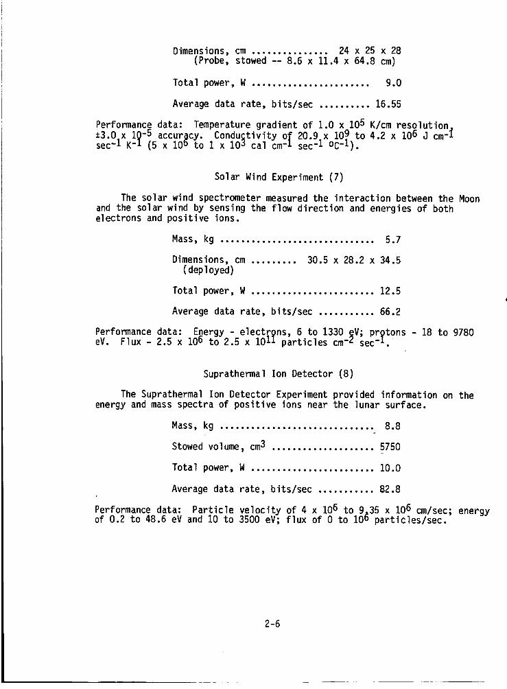
Solar Wind Experiment (7)
The solar wind spectrometer measured the interaction between the Moon
and the solar wind by sensing the flow direction and energies of bothelectrons and positive ions.
Mass, kg .............................. 5.7
Dimensions, cm ......... 30.5 x 28.2 x 34.5(deployed)
Total power, W ........................ 12.5
Average data rate, bits/sec ........... 66.2
Performance data: Energy - electrgns, 6 to 1330 _V; prgtons - 18 to 9780eV. Flux - 2.5 x 10o to 2.5 x 10II particles cm-L sec-i.
Suprathermal Ion Detector (8)
The Suprathermal Ion Detector Experiment provided information on theenergy and mass spectra of positive ions near the lunar surface.
Mass, kg .............................. 8.8
Stowed volume, cm3 .................... 5750
Total power, W ........................ 10.0
Average data rate, bits/sec ........... 82.8
Performance data: Particle velocity of 4 x 10⁶ to 9_35 x 106 cm/sec; energyof 0.2 to 48.6 eV and 10 to 3500 eV; flux of 0 to 10b particles/sec.
2-6
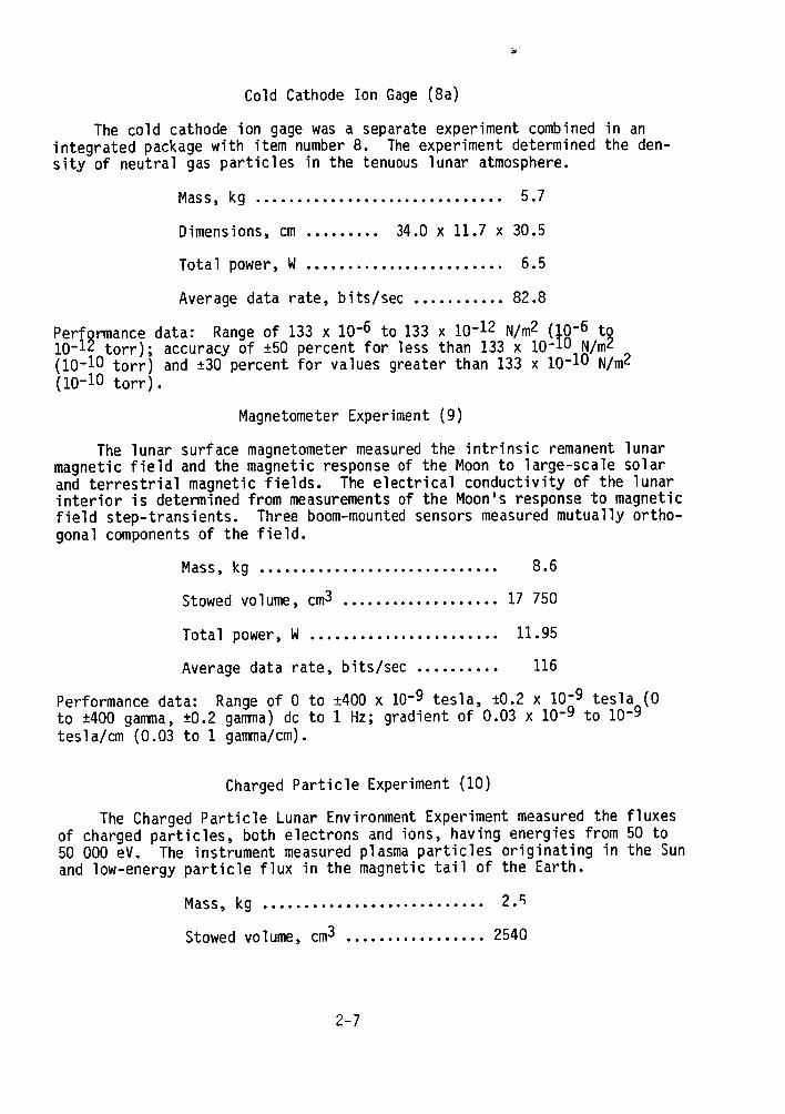
Cold Cathode Ion Gage(8a)
The cold cathode ion gagewasa separate experiment combinedin anintegrated packagewith item number8. Theexperiment determined the den-sity of neutral gas particles in the tenuous lunar atmosphere.
Mass, kg .............................. 5.7
Dimensions, cm ......... 34.0 x 11.7 x 30.5
Total power, W ........................ 6.5
Average data rate, bits/sec ........... 82.8
PerfQrmancedata: Rangeof 133 x 10-6 to 133 x 10-12 N/m2 (10-6 to10-Iz torr); accuracy of ±50 percent for less than 133 x 10-lu N/mZ(10-10 torr) and ±30percent for values greater than 133 x 10-lu N/m2(10-10 torr).
MagnetometerExperiment(9)
The lunar surface magnetometermeasuredthe intrinsic remanentlunarmagnetic field and the magnetic responseof the Moonto large-scale solarand terrestrial magnetic fields. Theelectrical conductivity of the lunarinterior is determined from measurementsof the Moon's response to magneticfield step-transients. Three boom-mountedsensors measuredmutually ortho-gonal componentsof the field.
Mass, kg ............................. 8.6
Stowedvolume, cm3................... 17 750
Total power, W ....................... 11.95
Averagedata rate, bits/sec .......... 116
Performancedata: Rangeof 0 to ±400x 10-9 tesla, ±0.2 x 10⁻⁹ tesla (0to ±400gamma,±0.2 gamma)dc to 1 Hz; gradient of 0.03 x 10⁻⁹ to 10-9tesla/cm (0.03 to 1 gamma/cm).
ChargedParticle Experiment(10)
The ChargedParticle Lunar EnvironmentExperimentmeasuredthe fluxesof charged particles, both electrons and ions, having energies from 50 to50 000 eV. The instrument measuredplasmaparticles originating in the Sunand low-energy particle flux in the magnetic tail of the Earth.
Mass, kg ........................... 2._
Stowedvolume, cm3 ................. 2540
2-7
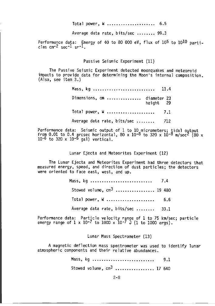
Total power, W ..................... 6.5
Averagedata rate, bits/sec ........ 99.3
Performancedata: Energy of 40 to 80 000 eV, flux of 105 to 1010parti-cles cm-2 sec-1 sr-1.
Passive Seismic Experiment (11)
The Passive Seismic Experiment detected moonquakesand meteoroidimpacts to provide data for determining the Moon's internal composition.(Also, see item 3.)
Mass, kg ........................... 11.4
Dimensions, cm ............... diameter 23height 29
Total power, W ..................... 7.1
Averagedata rate, bits/sec ........ 712
Performancedata: Seismic output of 1 to lO^micrometers; _idal o_tputfrom 0.01 to 0.4 arcsec horizontal, 80 x 10-_ to 320 x 10-_ m/secz (80 x10-6 to 320 x 10-6 gal) vertical.
Lunar Ejecta and Meteorites Experiment (12)
The Lunar Ejecta and Meteorites Experimenthad three detectors thatmeasuredenergy, speed, and direction of dust particles; the detectorswereoriented to face east, west, and up.
Mass, kg ........................... 7.4
Stowedvolume, cm3 ................. 19 480
Total power, W..................... 6.6
Averagedata rate, bits/sec ........ 33.1
Performancedata: Particle velocity range of 1 to 75 km/sec; particleenergy range of 1 x 10⁻⁷ to 1000x 10-/ J (1 to 1000 ergs).
Lunar MassSpectrometer (13)
A magnetic deflection massspectrometer wasused to identify lunaratmosphericcomponentsand their relative abundances.
Mass, kg ........................... 9.1
Stowedvolume, cm3 ................. 17 640
2-8
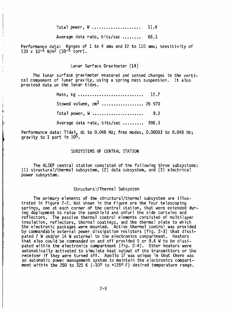
Total power, W ..................... 11.4
Averagedata rate, bits/sec ........ 66.3
Performancedata: Rangesof 1 to 4 amuand 12 to 110 amu;sensitivity of133 x 10-5 N/m2 (10-5 torr).
Lunar Surface Gravimeter (14)
The lunar surface gravimeter measuredand sensedchangesin the verti-cal componentof lunar gravity, using a spring masssuspension. It alsoprovided data on the lunar tides.
Mass, kg ............................ 12.7
Stowedvolume, cm3 .................. 26 970
Total power, W ...................... 9.3
Averagedata rate, bits/sec ......... 596.3
Performancedata: Tidal. dc to 0.048 Hz; free modes,0.00083 to 0.048 Hz;gravity to 1 part in 105.
SUBSYSTEMSOFCENTRALSTATION
The ALSEPcentral station consisted of the following three subsystems:(1) structural/thermal subsystem, (2) data subsystem,and (3) electricalpowersubsystem.
Structural/Thermal Subsystem
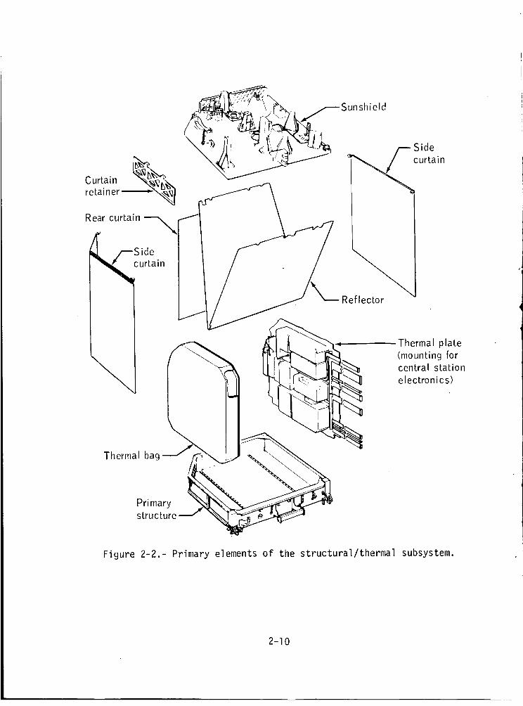
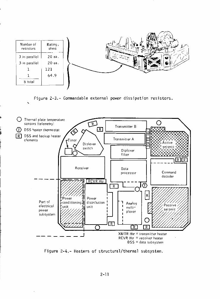
The primary elements of the structural/thermal subsystemare illus-trated in figure 2-2. Not shownin the figure are the four telescopingsprings, one at each corner of the central station, that were extendeddur-ing deploymentto raise the sunshield and unfurl the side curtains andreflectors. The passive thermal control elementsconsisted of multilayerinsulation, reflectors, thermal coatings, andthe thermal plate to whichthe electronic packageswere mounted. Active thermal control wasprovidedby commandableexternal powerdissipation resistors (fig. 2-3) that dissi-pated 7 Wand/or 14 Wexternal to the electronics compartment. Heatersthat also could be commandedon and off provided 5 or 9.4 Wto be dissi-pated within the electronics compartment(fig. 2-4). Other heaters wereautomatically activated to simulate heat output of the transmitters or thereceiver if they were turned off. Apollo 17was unique in that there wasan automatic powermanagementsystem to maintain the electronics compart-ment within the 250 to 325 K (-10° to +125o F) desired temperature range.
2-9
Thermal plate(mounting forcentral station
electronics)
Figure 2-2.- Primary elements of the structural/thermal subsystem.
2-10
Number of Rating,resistors ohms
3 in parallel
.3 in parallel
1
1
8 total
20 ea.
20 ea.
121
64.9
Figure 2-3.- Commandable external power dissipation resistors.
0 Thermal plate temperature _ ,
sensors (telemetry) / LM, I<_ DSS heater thermostat /_ _,,, l_ , TransmitterB
[] DSS and backup heater / v / "_ I
elements /[_m_sDwPl_er _[ Transmitter A
Diplexerfilter
Receiver [ Dataprocessor
. DE][ :Power
Partof distribution 1 Analogelectrical unit
powersubsystem
iPower
,conditioninglunit
E0
I multi-
I plexerIII
] ,EE3
0 \
Comm , dec°derI
XMTR Htr = transmitter heater
RCVR Htr = receiver heater
DSS = data subsystem
Figure 2-4.- Heaters of structural/thermal subsystem.
2-11
Data Subsystem
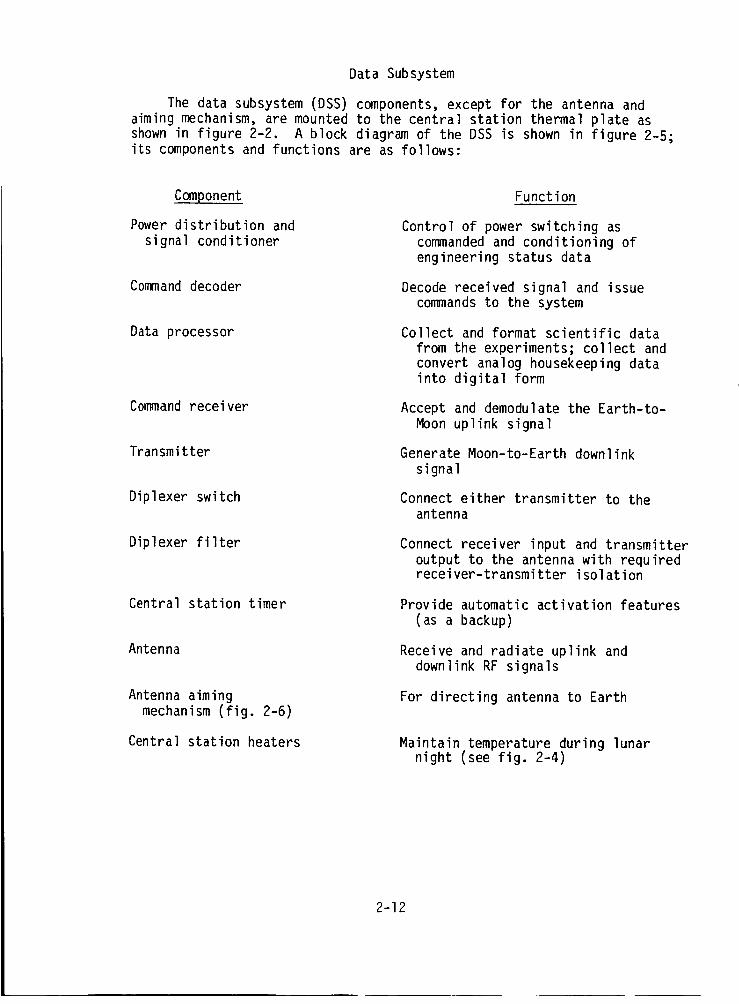
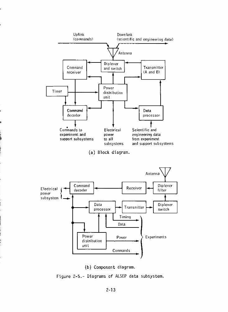
The data subsystem (DSS) components, except for the antenna andaiming mechanism, are mounted to the central station thermal plate asshown in figure 2-2. A block diagram of the DSS is shown in figure 2-5;its components and functions are as follows:
Component
Power distribution and
signal conditioner
Command decoder
Data processor
Command receiver
Transmitter
Diplexer switch
Diplexer filter
Central station timer
Antenna
Antenna aimingmechanism (fig. 2-6)
Central station heaters
Function
Control of power switching ascommanded and conditioning ofengineering status data
Decode received signal and issuecommands to the system
Collect and format scientific datafrom the experiments; collect andconvert analog housekeeping datainto digital form
Accept and demodulate the Earth-to-
Moon uplink signal
Generate Moon-to-Earth downlinksignal
Connect either transmitter to theantenna
Connect receiver input and transmitteroutput to the antenna with requiredreceiver-transmitter isolation
Provide automatic activation features(as a backup)
Receive and radiate uplink anddownlink RF signals
For directing antenna to Earth
Maintain temperature during lunarnight (see fig. 2-4)
2-12
Timer
Uplink(commands)
Command
receiver
Command I_decoder
Commands to
experiment andsupport subsystems
Down link
(scientific and engineering data)
yAntenna
Diplexer I =and switch Transmitter(A and B)
11 "
Power 1distributionunit
L IDataprocessor
fElectrical Scientific and
power engineering datato all from experimentsubsystems and support subsystems
(a) Block diagram.
Electrical {_.__powersubsystem
Antenna T
C°mmandi I I._ Diplexerdecoder _ Receiver fi Iter
tI Data FI ]-_1 D_plexer; : processor Transmitter switch
II Data
I Power Power Experimentsdistribution
unit
Commands ,.r
(b) Component diagram.
Figure 2-5.- Diagrams of ALSEP data subsystem.
2-13
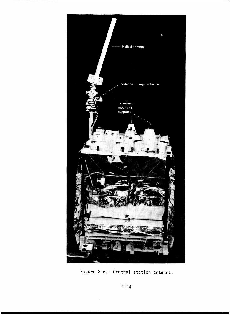
I Figure 2-6.- Central s t a t i o n antenna.
2-1 4
Data subsystem antenna.- The central station antenna was the modifiedaxial-helical type shown in figure 2-6. Antenna parameters were as follows:
Length, cm ........................ 58
Diameter, cm ....................... 3.8
Pitch, deg ......................... 15
Mass, g ............................ 580
The uplink frequency for all the Apollo missions was 2119 MHz; downlinkfrequencies were as follows:
Apollo mission Frequency, MHz
12 2278.5
14 2279.5
15 2278.0
16 2276.0
17 2275.5
Data subsystem function.- The data subsystem received, conditioned,stored, and formatted the ALSEP scientific and engineering data that werethen transmitted by an RF modulated signal to the manned space flight net-work (MSFN) receiving stations. Ground-based "command data" were alsoreceived by the data subsystem from the MSFN and were subsequently demodu-lated, decoded, and routed to appropriate ALSEP subsystems as separatediscrete command functions. The signal processing functions of the datasubsystems were for both uplink and downlink data.
Uplink: The ALSEP system was controlled from Earth by commandstransmitted by MSFN stations. These commands were received as an RF
signal input to the helical antenna and routed by the diplexer filter to
the command receiver (fig. 2-5(b)). The command receiver demodulated theinput carrier and provided a modulated subcarrier output to the commanddecoder. The command decoder processed this information, converted it
into a digital format, and decoded the digital information into discreteALSEP subsystem commands.
Downlink: Scientific and engineering status data were collected fromexperiment and supporting subsystems and routed to the data processor inboth digital and analog forms. These data were collected according to apreprogramed format stored in a programmable commutator. The analog sig-nals were routed through a multiplexer to an analog-to-digital converter,where each analog input was converted into an 8-bit digital word and thencombined with other digital data in a prescribed telemetry format. Thedigital output of the data processor was routed to the transmitter whereit phase-modulated the RF carrier.
2-15
Portions of the downlink configuration were implemented with redun-dant sections either of which could be selected by command. Two separate
transmitters were provided, either of which could also be selected by com-mand. The Apollo 16 and 17 ALSEP stations contained redundant receivers.
Electrical Power Subsystem
The electrical power subsystem (EPS) provided the electrical powerfor lunar surface operation of the ALSEP. Primary electrical power wasdeveloped by thermoelectric action, with thermal energy supplied by a ra-
dioisotope source. The primary power was converted, regulated, and fil-tered to provide the six operating voltages for the ALSEP experiment andsupport subsystems.
Figure 2-7 is a block diagram of the EPS that consisted basically of
the radioisotope thermoelectric generator (RTG) and the power conditioningunit (PCU). These two components are shown in figures 2-8 to 2-10. Thepower distribution unit (PDU), although a part of the data subsystem, is
also described here; figure 2-11 is a block diagram of the PDU. A power
control circuit for a typical ALSEP experiment is shown in figure 2-12.
The RTG, PCU, and PDU are described briefly in the following sub-
sections. (Note that the Apollo 11 EASEP was powered by solar energy; seefigure 2-1 and subsection entitled "EASEP Passive Seismic Experiment.")
Radioisotope thermoelectric 9enerator.- The generator assembly(model, SNAP-2/), with fuel capsule in place, weighed 17 kg (38 Ib) andproduced approximately 70W_(dc) at a nominal 16 V. Heat generated bydecay of the plutonium-238 radioisotope fuel was transferred by radiation
to a cylindrical hot frame in the generator. Spring loaded lead-telluride(Pb-Te) thermoelectric elements, mounted radially around the hot frame,converted heat directly to electrical power. These thermoelements weresealed in an inert atmosphere, and waste heat was rejected to a set ofradiating fins. Whenever possible, beryllium was used as the main struc-
tural material to minimize the weight. Other materials included Inconel
and Haynes supera110ys for_ s_re_th at high temperature. Thermoelements
wereconnectedt_i:as_!_arailel ladder arrangement to maximize relia-bil!_ty, prObl_B_lJ_t under tbemal cycllng (.lunar day-night
v_._j_a_): we___ra_i_a s_h_!cal seat at the outer end
ofi_jea_je!mat___z_._|_Ecs " 'of _RTG i!,are _sumart z_follows. ._i_ _L._ , i. ' .. " .
1. Conversion concept: Plutonium-238 (half life of 89.6 years)fueled a Pb-Te thermoelectric system.
2. Design life: 1 year for all missions except Apollo 17, which had
a design life of 2 years.
3. Design power: 63.5 W at end of design life of 1 year (2 yearsfor Apollo 17).
2-16
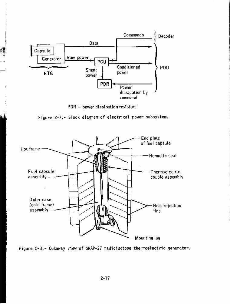
!CaosoelI OaaiOene,a_or_"_o°_e'.B,]RTG
Commands
Shunt
power
0
Conditioned
power
Power
dissipation bycommand
Decoder
t PDU
PDR = power dissipation resistors
Figure 2-7.- Block diagram of electrical power subsystem.
Hot frame
Fuel capsule
assembly
0 utercase(cold frame)
assembly
End p late
of fuel capsule
Hermetic seal
_ ]_ >f1:: trejectiOn
Figure 2-8.- Cutaway view of SNAP-27 radioisotope thermoelectric generator.
2-17
frame
frame
Heat
rejectionfins
Thermoelectric
coupleassemb
tellurid_
Boron nitride
insert
Hot frame
Hot shoe
Cold cap
Follower
Compression
spring
(a) Component schematic.
Cold frame
Temperature telemetry
to data subsystem
Thermoelectric
converter
(thermopi le)
Electrical
energy
[ P°we'Iheader
}/_ +16 V dcPCU
I Radioisotope Ienergy source
Radiative
heat
, transfer
_1 Hotframe I
I I, RadiativeThermal energy i heat
t _ transfer
I Coldframel
I Conductive heattransfer
Outer case land fins I
_ Thermalradiation
to space
(b) Block diagram.
Figure 2-9.- Schematic and characteristics of SNAP-27 radioisotopethermoelectric generator.
2-18
>
i--I
+
E
I-
0
+I
EIlJ
r --_
C
> > > >
+"1" Ii
+
O
i
i
E
_._ o
-_ oE _
-o "_
• i
{.C
m_
o
O
°--
.=_
E
i
e-
i
J
c_EO
>,or-I
2-19
(.3
>
+
j
C:
._. -_ __
E I,- m
F- _ ¢Y
_e4_,_ _ °
"r--,s
e-
0.p..
.r--._
c-
O
c_
_,_
o
0
$.,.
°r-.
0
e-,-
I
C_
I
",1
._,..
I.I-
Load and heaterpower control
romPCU OP°werI!,decoderFrom command _, 0 Commands
Reserve power
signal _ Power off H ExperimentReference sequencer power control
signal
Sensors } q
From sensors } 0
I_,.{ToPower to sensors experiments
Sensor signal
To power dissipation resistorsand central station
Data
processorpowerco ntro I
', ' contro I
Transmitter kpowercon tro I
Telemetry _signalprocessing
Figure 2-11.- Block diagram of power distribution unit.
"Operator select";- 29 V dc experiment
Switch ]" Relay _--_I Circuit l°peratingp°wer[ I9
+29Vdc _ no. 1 F breaker
tTrip
"Standby select"
Experiment /-- =ripple-off Psequencer
I 29 V dc experiment
Relay ll i standby p°wer
no. 2
t To summing network"Standby off" F-_ for telemetry©
Reset
1-%Fuse
,Figure 2-12.- Power control circuit for typical ALSEP experiment.
2-20
4. Physical characteristics:
.... 46 by 40Outer dimensions, cm (in.) ..... i18.1 by 15.7)
Number of thermoelectric couples ...... . . . 442Generator weight, kg (Ib) ............ 12 (26)
5. Nominal operating temperatures were as follows:
Hot junction:
Lunar midnight, K (OF) ............. 839 (1050)Lunar noon, K (OF) ............... 866 (1100)
Cold junction:
Lunar midnight, K (OF) ..............Lunar noon, K (OF) ................
533 (500)505 (450)
Power conditioning unit.- The PCU performed three major functions:
(1) voltage conversion, (2)voltage regulation, and (3) RTG protection. Ablock diagram of the PCU is shown in figure 2-10. Each power conditionerconsisted of a dc-to-dc power converter (inverter and rectifiers), whichconverted the RTG 16-V input to the six operating voltages, and a shunt
current regulator to maintain the output voltages within approximately ±1percent. This also regulated the input voltages and thus maintained aconstant load on the RTG. It was necessary to maintain a constant load on
the generator to prevent overheating of the thermocouples in the RTG.
As indicated in the block diagram, the +16 V from the RTG was appliedthrough the switching circuit to the selected dc-to-dc converter, applying
power to the inverter and completing the shunt regulation circuit. Apply-ing power to the inverter permitted it to supply ac power to the rectifiersthat developed the dc voltages applied to the filters. The outputs fromthe filters werethe six operating voltages applied to the data subsystem.
Output and input voltages were regulated by feedback from the +12 Voutput to the shunt regulator. The +12-V feedback was also applied to the
switching circuit for over or under voltage determination and for switch-
ing to the redundant inverter and regulator, if necessary. All the outputvoltages were regulated by the 12-V feedback.
Power distribution unit.- The PDU (figs. 2-11 and 2-12) distributed
power to experiment and central station subsystems and provided circuitoverload protection and power switching of selected circuits. The PDU
also provided signal conditioning of selected central station and RTGtelemetry monitor signals prior to input to the analog multiplexer for
analog-to-digital conversion and subsequent data transmission to Earth.
The power-off sequencer of the PDU detected minimum reserve power and
sequentially placed up to three preselected experiments on "standby" tobring the power reserve within acceptable limits. The minimum reserve
2-21
powerwasdetected by monitoring the voltage across the shunt regulatortransistor. This voltage was applied to an operational amplifier used asa level detector. An RCdelay network wasused at the output of the leveldetector. The output of the delay wasapplied to a secondlevel detectorthat drove the power-off sequencer logic. This arrangementturned on thepower-off sequencerlogic input gate whenthe reserve powerdropped belowthe levels as follows: reserve powerto start experiment turn-off (135millisecond delay) was0.78 W-+0.57W.
2-22
3. DATA MANAGEMENT AND ALSEP OPERATION
Control of the Apollo Lunar Surface Experiments Package (ALSEP) was ac-
complished through the Manned Space Flight Network (MSFN). The operationalmanagement and the data collection were a function of ALSEP Control Teams.
TRACKING STATIONS
The MSFN, a worldwide network of tracking stations, was in communicationwith the NASA Goddard Space Flight Center (GSFC) and the NASA Lyndon B.
Johnson Spa_ _er (JSC'T.--_&flow diagram of the communication network isshown in figure 3-1, and the ALSEP supporting stations and the equipment con-figuration are given in table 3-I. Command capability was through the MSFNground stations with instructions from the Mission Control Center (MCC) atJSC; the technical coordination, e.g., station scheduling and so forth, wasthe responsibility of the GSFC Operation Manager (MSFNOM). The MSFN recordedALSEP data on a continuous 24-hour/day basis and the recorded data were sent
to JSC for processing and distribution to individual Principal Investigators(PI's).
ALSEP CONTROL TEAMS
Special Control Teams, directed by the ALSEP Senior Engineer (ASE), were
assigned to each ALSEP; a functional diagram of the coordination effort is
given in figure 3-2. The team responsibilities were as follows:
I. Coordinate ALSEP deployment and activation of the experiment equip-ment
2. Implement contingency procedures for crew activities during ALSEP
deployment
3. Exercise operational control of ALSEP(s) after initial activation
4. Ensure maximum return of scientific data from the ALSEP equipment
during its useful lifetime
The ALSEP Control Teams were responsible for preparing numerous docu-
ments based on data supplied by individual PI's, contractors, hardwarevendors, and similar scientific personnel. The scope and extent of thisplanning effort are indicated in the following list of typical documentsprepared for an ALSEP.
3-I

TABLE 3-I.- ALSEP SUPPORTING STATIONS AND EQUIPMENT CONFIGURATION
MSFN
facility
MCC
MSFNOC a
ACN
ANG
BDA
CRO
CYI
GBM
GYM
'GDS
GWM
HAW
HSK
MIL
MAD
TEX
Location Unified S-band antenna
for telemetry updata
and tracking
85-foot 30-foot 30-foot
dual single dual
Houston, Tex.
Greenbelt, Md.
Ascension Is. X
Santiago, XChile
Bermuda X
Carnarvon, X
Australia
Canary Is. X
Grand Bahama X
Guaymas, XMexico
Goldstone, XCalif.
Guam Is. X
Hawaii X
Honeysuckle, XAustralia
Merritt Is., XFla.
Madrid, Spain X
Corpus Christi, XTex.
High-speed Voice
telemetry (SCAMA a)data
X
X
X X
X X
X X
X X
X X
X X
X X
X X
X X
X X
X X
X X
X X
X X
TTya
aNotes: SCAMA = switching, conferencing, and monitoring arrangement; TTY = teletype;
RSDP = remote site data processor; MSFNOC = MSFN Operations Control.
ALSEP
RSDP a
computer
3-2
Moon
ALSEPDownlink JSC
(scientific "_ *"/, JSC computation and
Uplink data) / analysis division (off line) \
(commands) \
Earth
//
Figure 3-1.-
\%
PI tapes
ALSEP communication network.
NASAIJSC lmanagement
Figure m2.--
JSC/contractor
scientific and technical
personnel
1ALSEP
Control Teams
FFlight control
personnel
I MSFN stations I
Functional diagram of ALSEP
]I I
coordination.
3-3
1. ALSEP Systems Handbook: The ALSEP Systems Handbook was a functional
representation of ALSEP systems and was prepared in a format for real-timeuse by ALSEP controllers. The information enabled most contingencies to bedetermined and solved in real time.
2. ALSEP Mission Rules: The ALSEP Mission Rules were preplanned solu-
tions and guidelines for single-point failures of the systems hardware.
3. Apollo Spacecraft Operational Data Book, Vol. VI (SODB): The SODBwas a collection of hardware operational specifications; its primary use was
the preparation of related documentation.
4. ALSEP Contingency Procedures: The ALSEP Contingency Procedures werea collection of alternatives to standard crew deployment procedures. The pro-cedures were listed by system and experiment to enable their optimal use
during the lunar deployment of ALSEP.
5. Lunar Surface Flight Plan: The Lunar Surface Flight Plan was thatpart of the overall Flight Plan that was used while the flightcrew was on thelunar surface. The flightcrew used this material in the format of a "cuff"check list.
6. ALSEP Console Handbook: The ALSEP Console Handbook was a collection
of console operating procedures used by the ALSEP controllers in real-time
support.
7. ALSEP Operations Report: The operations report was in two parts:(1) a summary support plan and (2) a parameter listing. The support plan was
a weekly guide to the planned activities during real-time support. The param-eter listing was completed from the last data obtained before termination of
support.
8. ALSEP Mission Operational Documentation: Data for this type of docu-
ment were collected during the mission and were prepared for ALSEP analysisand historical documentation.
9. Activity Plannin9 Guide: This planning guide began at lunar module(LM) ascent stage impact and was a real-time support schedule and activity
guide for all deployed ALSEP equipment.
10. Data Book: A Data Book for each ALSEP was kept in the OperationRooms. A new Data Book was started for each ALSEP at its sunrise (Sun angle
of zero). High-speed printer formats were placed in the Data Book in thefollowing order: Central Station, Experiment 1, Experiment 2, Experiment
3, Experiment 4, and Experiment 5. The central station format had a "tab"placed on it with the following information: day of year, date, and universaltime (Greenwich mean time). The formats were obtained at the beginning andend of each support period and at even universal-time hours. In the event
of a contingency problem, a format of the contingency was placed in each bookand a "tab" written in red stating the problem and experiment affected.
3-4
11. Console Log: The Console Log was a history of everything thatoccurred during the support periods. The log reflected all commanding andanomalies; it also detailed the accomplishments. Important information waswritten in red; routine information was in black.
12. Deployment Log: The Deployment Log was an account of all opera-tions during the time period from initial deployment on the lunar surface tothe beginning of normal ALSEP operation.
13. SPAN Mission Evaluation Action Request (SMEAR): A document, com-monly known as SMEAR, was prepared for two reasons: {1) to determine thecause of ALSEP problems and (2) to request action from a supporting organiza-tion. (SPAN = spacecraft analysis)
FLIGHT CONTROLLER PERSONNEL
Coordination and direction of ALSEP systems during an actual Apollo mis-sion was the responsibility of three flight controller positions.
1. ALSEP Senior Engineer (designated ASE) -- The ASE was responsiblefor directing all activity in the ALSEP control area (room 314) at the MCC.As described previously, he was also director of the ALSEP Control Team andits activities.
2. ALSEP Systems Engineer (designated SYSTEMS) -- During a given Apollomission, this position provided real-time response to all questions or prob-lems relative to ALSEP equipment or experiment systems.
3. ALSEP Data Engineer (designated DATA) -- The DATA position during anApollo mission was responsible for real-time data acquisition and for re-sponse to real-time data problems or questions.
These positions were staffed by NASA and contractor personnel who werecross trained to achieve maximum flexibility with minimum manning. Becauseof the physical layout of display equipment in the ALSEP control area (room314 in MCC), a minimum of two staff members were required for each supportperiod.
OPERATION ROOMS
Configuration of the Operation Rooms changed slightly during the se-quence of Apollo missions, but a generalized layout is illustrated in figure3-3. The ALSEP control area was staffed by flight controller personnel; theoffice/support area was staffed by technical staff and experiment scientists.Console 88 was the center of operations and the communications loop requiredtwo "comm" positions in front of the console. A modified universal commandsystem was used for real-time commands and the system consisted of two panels(command control module and digital select module).
3-5
Room 314B
ALSEP
control area
W
U[JAnalog recorders
J
Console 88
IJ
L
0[]Analog recorders
High-speed Jprinter
m
m
m
Drum recorders
Pneumatic
tube
|
I
,, \fq, _
Room 314A
office/support
area
Console Console
Figure 3-3.- Layout of ALSEP
I
Operation Rooms.
3-6
Requirements called for receiving data simultaneously from two ALSEP
central stations, and rapid access to hardcopy printouts was provided by
a high-speed printer. Four (8 pen) analog recorders were provided for
displaying data, and the capability existed for real-time switching betweenALSEP's and between data formats. The data formats were defined and imple-
mented before the mission. The eight drum recorders were provided with vari-
able input filters and were dedicated for support of the Passive Seismic Exper-iment.
OPERATIONS PLANNING MEETINGS
Operations planning meetings were held periodically to discuss ALSEP sta-tus; also to decide the nature of future ALSEP operations and the schedule of
these operations. The chairman of each meeting was a representative of theMCC Flight Director, and its members included representatives from (1) the JSC
Science and Applications Directorate, (2) the JSC Lunar Science Program Of-fice, (3) the PI's of the scientific community, (4) the ALSEP flight control-lers, and (5) other representatives concerned with special aspects of a givenmission.
REFERENCE FILE
During each Apollo mission, a reference file was maintained in the con-trol area, and each file included the latest issues of the following three
types of documents:
1. Operational documentation: This information included the opera-tional documentation prepared by the ALSEP Control Teams or the relatedmaterial based on these data.
2. Appropriate vendor and contractor material such as specifications,
calibration curves, and so forth.
3. Data collected during ALSEP test and support periods.
ALSEP DATA
Real-Time Data to JSC
The data transmitted directly (hardlined) in real time to the ALSEP Oper-
ation Rooms in the MCC included high-speed printer copy, teletype copy, ana-
log charts, drum recorder charts, and miscellaneous text prepared during real-time operations or as a result of these operations. These data were collectedfor either operational or scientific purposes, but no format distinction existed
between the two groups. Classification can be based only on the intendeduse.
3-7
1. Operational data: Operational data were used to assess the opera-tion of ALSEP systems and to provide a baseline for future operations.
2. Scientific data: Scientific data were distributed to the appropri-ate PI for cursory analysis; e.g., that the system was outputting valid andmeaningful data.
Experiment Data
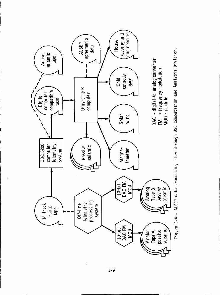
Telemetry data from the ALSEP stations on the lunar surface were re-corded 24 hours a day by the worldwide tracking stations. Data were recordedon analog tapes that were then shipped from the tracking station to the JSCComputation and Analysis Division for further processing and distributionto the Pl's (fig. 3-4). At JSC, the incoming analog tapes (range tapes) wereprocessed with the CDC 3200 computer, and the output was a time-edited andcomputer-compatible digital tape. The digital tapes were then processed ina Univac 1108 computer to produce tapes with data for the specific ALSEP exper-iments needed by the various Pl's. To preserve proprietary rights to thedata, each tape contained only the data for a specific experiment. The time-edited digital tape was retained by the JSC Computation and Analysis Divisionuntil the PI had verified that the experiment tape was usable and anothertape would not be required.
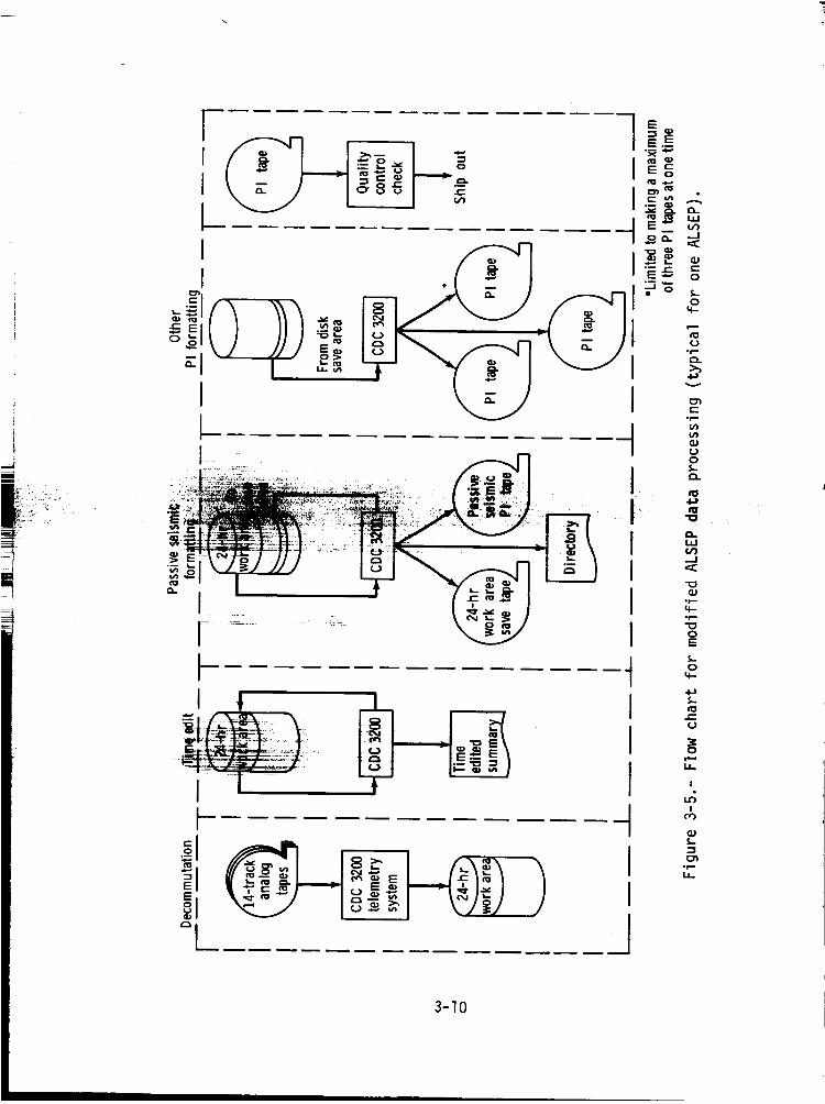
As the Apollo Program continued and more ALSEP stations were operating,the increased data flow impacted the Univac 1108 computer and data deliveriesto the Pl's were delayed by as much as 90 days. Processing procedures werethen modified to use the CDC 3200 exclusively as shown in figure 3-5, butwith no change in the PI tape format. This change reduced the waiting periodand permitted a 45-day delivery to the PI.
For data collected up to March 1973, the raw-data analog tapes from theMSFN stations (range tapes) were archived at the Federal Record Center. Beginningin March 1973, the digital time-edited tapes (fig. 3-5) were stored as thearchived data. By this time, more research was underway and the requestsfor archived data were increasing; therefore, the change to the direct computer-compatible digital tapes was implemented to reduce the costs of data retrieval.
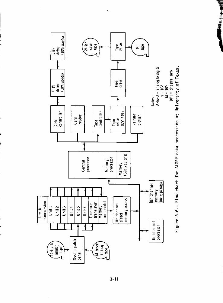
By mid-1975, the analysis contracts with individual Pl's were terminated(except for the Passive Seismic Experiment). However, data flow from fivestations on the lunar surface continued and the cost of data processing re-mained constant. To decrease the cost of this function, data processing wastransferred to the University of Texas at Galveston where newer, smaller,and more versatile computers and equipment could be used. The transfer wascompleted in March 1976, and the processing flow diagram is shown in figure3-6.
3-8
o_ _ _
0
"gI,,.. °
,.- ;g
o :.= "g(J ('0 >._
(1:1 0
'- E
,4--, E: n:l
.__ sII II II "1
I:::l.
3-9
I
I
(_ .._E_o_
I!
-I o')
I °°1-,1.1_
I
]3-10
I
I
fo
Z
II II II II
I
1
I
_ o x
...i.2
I
XQ;t--
0
-m.-
"7_
U0
.,-1
0
4_
e-U
0
!
!
°_,,.
3-11

ARCHIVING
Scientific analysis of ALSEP data was accomplished by NASA contractswith specific investigators, and these contracts stipulated the archiving ofanalyzed data. At the end of the Apollo Program, archiving received more at-tention, and JSC management believed that information obtained from the ALSEPstations should be in a form that approached as near as possible the "rawdata" stage (range tapes) of the MSFN stations; i.e., with only noise removedand timing corrected.
To ensure proper data archiving, JSC management created the GeophysicalData Evaluation Working Group with representatives from the Massachusetts In-stitute of Technology, California Institute of Technology, University ofCalifornia at Los Angeles, University of Texas at Dallas, University of Texasat Galveston, General Electric Co., NASA Ames Research Center, the JSC, theGSFC, NASA Headquarters, and the NSSDC.
The group was asked to study the data processing and make recommenda-tions on the archiving and distribution most appropriate for the present andfuture needs of the scientific community. Critical decisions were neededconcerning how, where, and in what form to store the data. Highlights of thestudy were as follows:
I. It would be neither practical nor desirable, in most cases, to dis-tribute the raw data from the range tapes. Therefore, the group concludedthat NASA should store, for use by other scientists, only data reduced andcorrected by the PI. They believed the PI best understood the conditionsunder which the data were acquired and the pertinent details of the instrumen-tation.
2. The group concluded that some analyzed data should be stored becausemany studies could be made from such data without further processing.
3. The group agreed that microfilm of reduced data (in some cases onlyfor special events) should be stored for dissemination, because this form wasconvenient for inspection by investigators.
4. Proper documentation was emphasized as an essential part of thearchiving process. Without adequate documentation and supporting information(ephemeris, for example), the stored data would be of limited use.
5. Data from complementary experiments (e.g., Lunar Surface Magnetome-ter and Explorer 35 Magnetometer) should be stored together or crossreferenced.
3-12
The study group surveyed the personnel, procedures, and facilities ofthe National Space Science Data Center (NSSDC) at GSFC. Alternatives, which
they considered, included individual PI responsibility for storage and distri-bution of data and creation of a special Apollo data facility independent ofNSSDC.
The final decision was that ALSEP data be collected and archived at the
NSSDC in Greenbelt, Maryland.
NSSDC ARCHIVED DATA
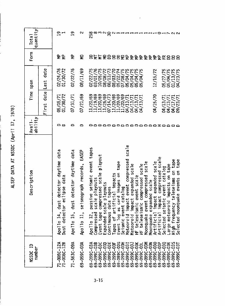
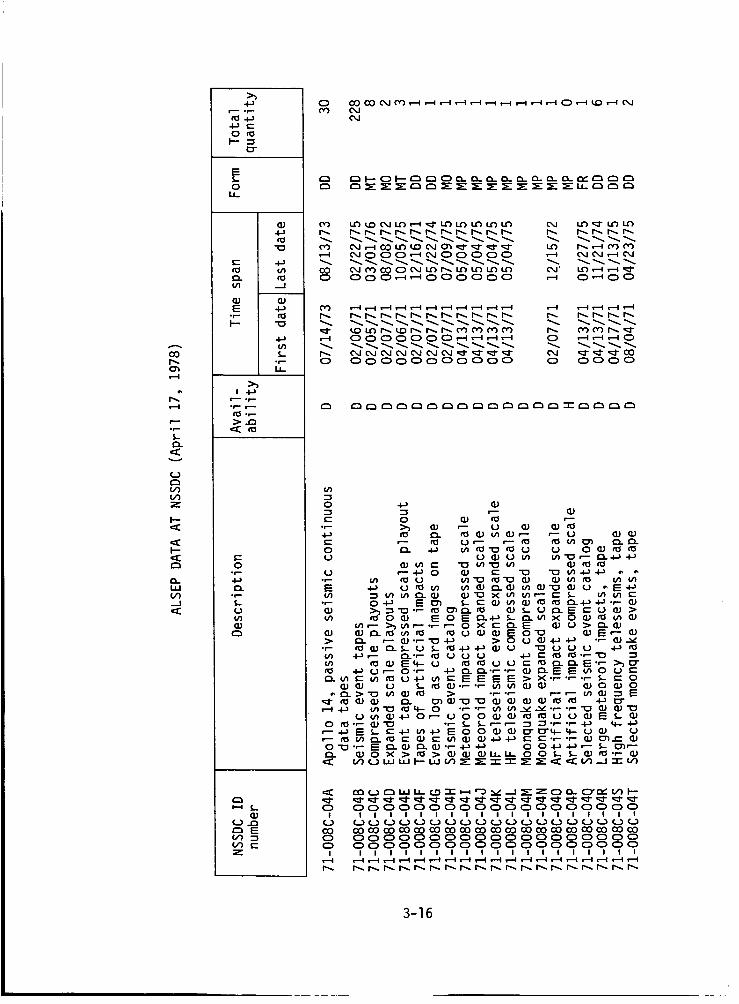
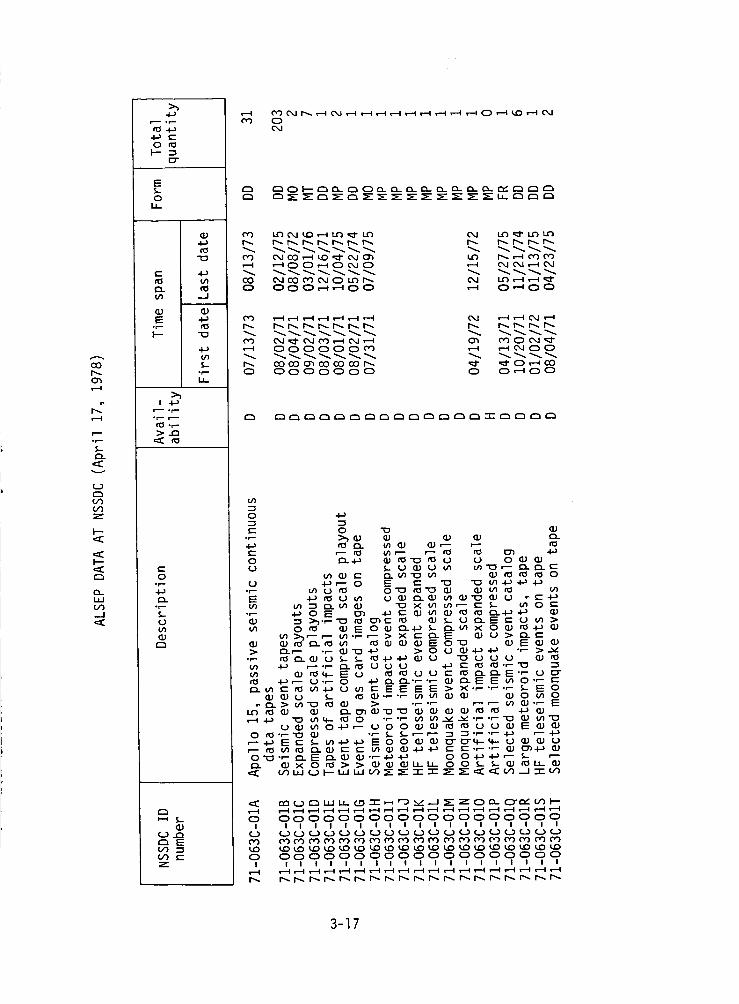
The ALSEP data archived at the NSSDC are given in the following pages.The following information is given for each entry.
NSSDC ID number: This number is the NSSDC identification number to be
used in requesting the material.
Description: This column provides a brief description or title of the
data item and should be included with data requests. As presented here, thearchived data are grouped by Apollo mission and subject of the experiment.
i The first entry in each group designates the Apollo mission and ALSEP experi-ment, and the subsequent entries designate other NSSDC data in this category.
Availability: Code letters in this column indicate the availability sta-tus as follows:
Code: Description:
Data at NSSDC and being processed at this date(April 17, 1978).
Data that has been identified and which NSSDC intends
to acquire but has not received at this date (April 17,
1978).
Proprietary data that can be distributed (April 17,
1978) only on the written request of the PI.
Time span: This column provides dates for the beginning and end of thedesignated data. Dates are given by month/day/year (e.g., 9/19/75).
Form: This column gives codes that identify the form of the data. Thefirst letter indicates the basic form of the material, the second letter indi-cates the dimensions.
3-13
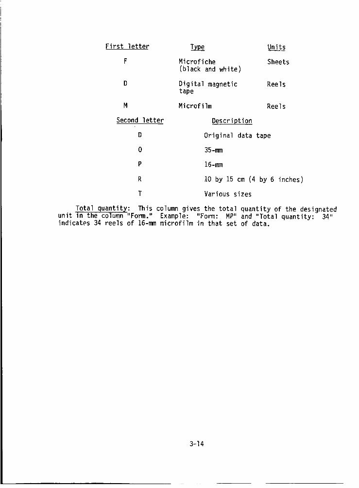
First letter Type
F Microfiche
(black and white)
D Digital magnetictape
M Microfilm
Second letter Description
D Original data tape
0 35-mm
P 16-mm
Units
Sheets
Reels
Reels
Total quantity:
unit in the column "Form." Example: "Form: MP" and "Total quantity:indicates 34 reels of 16-mm microfilm in that set of data.
R 10 by 15 cm (4 by 6 inches)
T Various sizes
This column gives the total quantity of the designated34"
3-14
00
,-4
"?.
OO
Z
U9-J
Ol.-
4._ c-O tD
I"--I=r
E
oI.L
c_
t0 _n
(D (D
• i-- fl_I-- "o
(.ni-
o_...u_
or--
c-O
or"
Q..
"?.
(D
t:3,--i K,.
t,_ ..a
z
O_ ,--i O'_ o4
,.._ CxJ
O400
C,,J ,--iOO
,-to4
I.t_OO09
i.¢) ,--_OO
__O____O_ _
_ _OOO_ O_OOOOO _ _O_
O O OO_OOOOOOOOO _ OOOO
_ __ ___ O
O O __O_O_OO O O OOOO
_ oo
ILl
E E ,2or- or-
_ O"O ,:l "O (.J
•._ Q),_ _ ._. .%-O"O O
•_ O- 4-* _-
"Or'-" "_ OO E
¢/) .r-
O"_ 0 O
O (n O O
o,I ¢,J,-t ,.-t
! I(..) ¢._COCO
8oI I
I",... t.,,
U
0
•_ 0 O__
""- O 4-_ I=: O'_ 4._ _" W (n (]J t_
:> (]J,"- 4-) .r- _ _J
aj co; o.o.,m r,.) G) _s. _
¢.J o t__,,0-o_-.- 4.-_ c- c-
•'o _/)4.._ c-
_ m
a.) Nr.- (lj
¢_ 0 ¢.) -t-) n=
°,--0 q-.-Ou,- 0 0 0""- aJ O_e- 0
,_ V) ._1 "_- V')
_ __ ___zO_O_
O O OOOOOOOOOOOOOOOOOOOOI I IIIIIIIIIIIIIIIIIIII
O O OOOOOOOOOOOOOOOOOOOO
O OOOOOOOOOOOOOOOOOOOOI I I|111111111111111111
3-15
O0
O_i-.-4
°r.-$.O.
v
0
U')
h-
h-
0.
-J
4-_ c-O cOh- -'
E
OU-
4-*r0
c" 4-Jr0 _nO. cO
qJE-'- f0h" "O
f.n
°_
! 4--*_m "r"
"_O '--
e"O°r"4--*O.°_
(JLnq)
¢.J "_'--' Eb0 --'IU9 e"Z
0 _____0__
_0_0____
_000_00000 _ __
0 000_000000 _ 0_00
0000000__ 0 _0
0 00000000000 0 0000
____ _ZO__
0 0000000000000000000I IIIIIIIIIIIIIIIIIII
0000 000000000000000 0000000000000000000I lllllllllllIl|lllll
3-16
O0
,--4
,--4
r--
ZID_
v
U9(29Z
I--
1--
13-
U9--.I
>,,
O
E%-0u-
cD
-J
E
I-- "Io
•r=-I,
r-- 0p-
°r-
C-O
"Z_3
r__-_ S-
Q.)_Q
r_ E
Z
_____0__0
_0__0____
_00_0_0 _ __
0 000_00 _ 0_00
___ _ _0_000000_ _ _00
___ _ _0_0 0000000 0 0_00
____ZO__
0 0000000000000000000I IIIIIIIIIIIIIIIIIII
0 0000000000000000000I IIIIIIIIIIIIIIIIIII
3-17
(3O
"[
v
o")
Z
<
<
<
oO_1<
>_
,_,,-c-
O rOI--"
_"
E
0LL
r_
,'_ on
-J
E
I-'-
°r-t.L
>_
:--- .r-
>,._D
c-O
"ZU(./)(D
.T,-(l)
(_._ rnr-n E(/) .-_
Z
_____0__
_0__0___ __
_00_0_0 _ _0_
0 O00_00 _ 0000
0 000_000 _ 0000
_O____ZO_O_
0 0000000000000000000I IIIIIIIIIIIIIiiiiii
0 0000000000000000000I IIIIIIIIIIIIIIIIIII
3-18
CO
Z
v
o')
Z
_CI--
O-LLI
0 cO
E
0I,
(_
t- .I_
.--I
4.-}
I-- -0
_)S-.r--I,
o_
or--
t-Oo_
Z0(/)OJC_
C_
OJ
r_ EGO(/) c-Z
_J I-_r-_O0
r_- _ C_C_
T-I O_
r-I O,J
L_0 0
r--I O,J
Lt')r--I O,J
O_ '_"0 0
0 00_
0 O0
,_- _-_0 0"_
_0_0
C_O0
tO t_
e- e-
•_-- 0t-- 0E E_--
_ _)-
o___ .r--_]_-_
o_ o_--
(0 _.)"_-
_ g'_,
0 0 Q/
0
I1.1E ¢_
_ or--
00.r-•_ _- ._
e-._- e-
E _E
U e" o_
_- 0 _.) _.--_ £_. e- __ _: 0"_
0 t-_
r-- "0 _I:--_ _._..
0 e,e_ E
0 O0 0 O0I I I I I I
CO _ _ 0",_0 coo') _ cr_0 C) O 0 oC)I I I I I I
OJ
0 O_ CO _- C_
_. _ _ _.
0 O0 0 0 0
o0o _) (xj _
0 O0 0 0
_ 0
_0 _0
0", 0r--.I Od
_:_ _¢_) _=_ _ _ _ ___
0 O0 0 0 0 0 0I I I I I I I I
0 O0 0 0 0 0 0I I | I I I I I
3-19
O0
,--I
I',..,.-I
ZO.
v
o')Z
h-
I--
O.LOV)._J
•i_ t-O t_
I--O"
E$-O
I.L.
QJ
tl5"10
c--
t'_ tOV_ _J
•r- n_I--- -O
4._
S-ot--LL.
t--- -r--
,:_ tU
c-O
.r-
"Z
r', E
z
r_ r_
o coo_ o
_.o odo
t--iI_ I_.
o') 09
r-., r'-.0 0
0 0 0I I I
'4O _O _00 0 0
! I I
r-_ r-_
0 _ _0_ _ _0_
0 _ __ _ ___ _0_ _ _0_
0 0 00000 0 00000
0 _ __ _ _0_00
0 0 0_0_ 0 00000
0 00000 0 00000I IIiii I IIIII
0 000_0 0 00_00
__ 0 000000 00000 0 00000
I iiiii I IIiii
3-20

¢0
0 _,
"Z
v
I---
I--
W
_1
._ c-O rO
I--O"
E
0L_-
_J
c.-
O.
Eor-I'--
r--- or-
"_ ,"--.t--
c-O
ot-
0..
"Z
QJr_
GJ_..) ..Q
EO0
Z
_0_O_
e_
C_0
O_fO 0
--.I
$- CO0or.-
Od OJ t-..I tOLO
_ 0 0
_0_ _ _ _ _ 0 0 0
00_ _
000_ _
00 cO
¢_1 ,--I 0_10 cO T_I
0 _ 0
I_o IF) _00 0 0
O,J Od0 0 0
_0_ __0_0 _
00000 0
Er..-0t.-
c-c- _,) v--OE_
QJ _-
_ fcs e-
o_or-
•_ e- a.)
0 00000 0 O0 0 0 0 0 0I IIIII I II I I I I I
__ _ _ 0 0 0 _0 00000 0 O0 0 0 0 0 0
I IIIII I II I I I I I
3-21
COr-.,,o'_I--i
r-'--
ZCl.
C..)
Or)Z
I---
I--.,<
IJ.Jt,/).--I
>_
,_.,- 4-_4-_ c-O
E
OL_-
"O
c- ._
-r-h" "O
t_
or-1.1--
e---ot--
"_ _-or-
c-Oot--
Q..r-
U
r_
r_ E
Z
o0 O OO O O
O O
O Odor)
Od
0 0 t-_ 0 _Z:, CZ__" _" _ _- ,.--, r'_
00 0 ,-_ r-.-,
,.--t _ (x.I cxJ
0 _ ,...-¢ _
0 0 ,--, ,--,
0 .f.-
0"_ _._ c--
o.=: _
_ 0
c- ¢_ c-
r."- e,.-- I_ ¢'_
0 <lJ 0 f.--
o_=__-- _._
O O _ _
r'_ -r- "I" -r r'_ r'_
I",- r-.,. ix') t.c, totO0 0 0 0 O0
I I I I I I
_ _ _ _0_0_0 _0 O_ Oh 0'_ 0'_0 0 0 0 O0I I I I I I
•--I O,J C_d 0,.ICXJ
0 0I I
CO CO0 00 0
! I
O_ 0,.I ,--' 0 _--_
O0
O0
cx.J ('xj,.-t O0
O0
r_ I'_ oo oo co oo0 0 0 0o0
I I I I I I_ (,-) (--_ (...) (--)
0 0 0 000I I I I I I
CX.I _ C'X.IC'_I C'XJ
3-22
4. OPERATIONAL HISTORY
Scientific data-gathering equipment and related communications equip-ment were deployed on the lunar surface during each of the six Apollo lunarlanding missions from July 21, 1969 (Apollo Ii mission), to December 12, 1972(Apollo 17 mission). The performance of the deployed equipment, which wasdesigned to provide data after the return of the crewmembers to Earth, isdescribed in this section. Performance details include the following:
. Time histories for each experiment are given up toSeptember 30, 1977, when the ALSEP program wasterminated.
e Annotation of the time histories provides backgroundinformation on significant events during the lifespanof each experiment.
e A status summary (September 29, 1977) of Apollo LunarSurface Experiments Package (ALSEP) performance is givenin table 4-I at the end of this section.
e Power output curves for the radioisotope thermoelectricgenerators (RTG's) are presented in figures 4-I to 4-5at the end of this section.
4-1
PASSIVESEISMICEXPERIMENT
Passive seismic 11
12
14
15
16 I
I
Leqend:
Science data outout
Housekeeping data
1971
lp a
Hi
I00 I
.972
,
1I
iil51
m
m
i
i d
I I
| I
Apollo Initial dateItem mission of occurrence
I 11 Aug. 27, 1969
2 12 Nov. 19, 1969
3 12 Nov. 22, 1969
4 14 Feb. 12, 1971
Status
PSE STANDBY mode. Station 11 operatedfor 20 Earth days before loss of theALSEP central station command uplinkterminated seismometer functions suchas leveling, gain adjustments, andcalibration.
SPZ component displaying reduced sen-sitivity at low signal levels. Theother three seismometers (LPX, LPY, LPZ)have operated properly since initialactivation.
Thermal control problems. These thermaldisturbances were most intense near sun-rise and sunset. They are believed tobe due to thermal contraction and expan-sion of the aluminized Mylar shroud thatcovers the sensor unit or to thermal con-traction and expansion of the cable con-necting the sensor unit to the centralstation, or both.
Thermal control problems. The modifiedthermal shroud used on Apollo 14 providedimproved thermal control. It was foundthat if the heater was commanded OFF forlunar day and AUTO for lunar night, thePSE temperature remained within the ex-pected range for Apollo 14.
4-2
PASSIVESEISMICEXPERIMENT- Continued
Item
5
8
Apollomission
14
15
16
12
Initial dateof occurrence Status
Mar. 20, 1972
Aug. 13, 1971
Apr. 24, 1972
Oct. 16, 1974
LPZ axis inoperative. Analysis of theproblem indicated this failure was eithercomponent failure or a wire connectionproblem. It was concluded that thefailure was random rather than generic.
Thermal control degradation. Reviewof lunar surface photographs showed thatthe periphery of the thermal shroud didnot lie flat on the lunar surface. Theincomplete deployment of the shroud re-sulted in excessive thermal leaks andloss of tidal data. For subsequent mis-sions, crew training emphasized the needfor the periphery of the shroud to beflat on the surface.
High temperature during lunar day. Photo-
graphs of the deployed experiment, tele-vision coverage of the lunar module as-
cent, and comments by the crew indicatedthe following as possible causes of theproblem: (1) some raised portions ofthe shroud, (2) dirt on the shroud from
crew traffic subsequent to the photo-raphy, (3) debris from lift-off, and
4) possible contact of the experimentwith the lunar surface. Any of the aboveconditions could cause degraded thermal
control, resulting in higher tempera-tures during lunar day.
The instrument was commanded to operatewith the feedback filter IN. The princi-pal investigator requested this operationto obtain data for comparison with datafrom filter OUT operation. The instrumentperformed satisfactorily with the feedbackfilter IN. Test was completed on Apr.9, 1975, and the instrument was returnedto the feedback filter OUT mode.
4-3
PASSIVESEISMICEXPERIMENT- Continued
Item
9
10
11
12
13
Apollomission
12
14
12, 15,and 16
14
12
Initial dateof occurrence Status
Nov. 7, 1974
Mar. 5, 1975
June 28, 1975
Aug. 31, 1975andSept. 3, 1975
Dec. 5, 1975
An operational check on Nov. 7, 8, and9, 1974, indicated that the heater couldnot be set in the auto OFF or forced OFFmodes. Preliminary analysis indicatedthe cause of the failure to be that theheater ON/OFF relay driver circuit failed"closed" allowing +29 V dc power to beapplied at all times.
No command capability; therefore, noleveling possible. Engineering datafrom the PSE were valid. Science data
from the PSE could be used for a period
of approximately 9 days when the longperiod y-axis moved from off scale highto off scale low (Sun angles 550 to 1090 )and off scale low to off scale high (Sun
angles 1850 to 2370). When Apollo 14central station uplink capability waslost, the PSE heater was in the forced
OFF mode for lunar daytime operation.
The instrument remains in this configu-ration.
Feedback filter IN. The instruments
performed satisfactorily in this configu-ration.
Although no leveling had been accomplishedon the PSE since Mar. 1, 1975, because
of the loss of command capability, aseismic event on these dates indicated
that data were discernible on the long
period x- and y-axis on the recorders.
Noise spike appeared in seismic dataas a result of the third bit not settingin the PSE electronics analog-to-digital
converter. Increasing the central sta-tion heat eliminated the problem.
4-4
Item
14
15
16
17
18
19
20
Apollomission
14
14
14
14
14
14
14
14
14
14
14
12
12
14
PASSIVE SEISMIC EXPERIMENT - Continued
Initial date
of occurrence Status
Feb. 19, 1976
Mar. 17, 1976
May 20, 1976
May 24, 1976
May 27, 1976
June 8, 1976
June 11, 1976
Sept. 18, 1976
Oct. 9, 1976
Nov. 12, 1976
Nov. 17, 1976
Apr. 14, 1977
Apr. 22, 1977
June 20, 1977
With return of uplink, subsequent at-tempts to command the feedback filter
IN have shown the loop to be inopera-
tive. The instrument was performingsatisfactorily with the filter out.
The long period y-axis could not be
leveled during the uplink capabilityperiod.
When loss of downlink and uplink occurredwith the Apollo 14 central station, thePSE was ON and the heater was in theforced OFF mode.
With return of downlink, the PSE was ON.
Y-axis successfully leveled for firsttime since Mar. 1, 1975.
Feedback loop filter OUT.
Lost downIink.
Acquisition of signal; instrument ON.Feedback filter OUT.
Feedback filter IN.
Loss of signal with instrument configuredto ON.
Acquisition of signal; instrument ON.
The lon_ period z-axis responded to level-ing; caJibration and seismic events pos-sible for first time since Mar. 1972.
Feedback loop filter OUT.
The long period z-axis seismic data arestatic.
The long period z-axis seismic data re-turned to normal.
Long period z-axis data static.
PASSIVE SEISMIC EXPERIMENT - Concluded
Item
21
22
23
24
Apollomission
12
14
15
16
Initial dateof occurrence
Sept. 30, 1977
Sept. 30, 1977
Sept. 30, 1977
Sept. 30, 1977
Status
Configured to STANDBY, could be commandedON.
Configured to STANDBY, could be commandedON.
Configured to OFF and should not be com-manded ON.
Configured to STANDBY, could be commandedON.
4-6
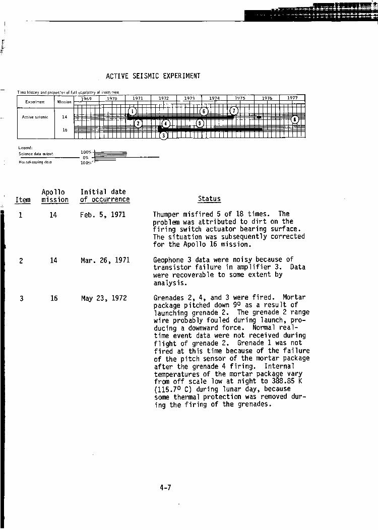
ACTIVESEISMICEXPERIMENT
Time history and proportion of full capability of instrument
Experiment
Active seismic
Legend:
Science data output
Housekeeping data 100%
Item
1
Apollomission
14
2 14
3 16
Initial date
of occurrence
Feb. 5, 1971
Mar. 26, 1971
May 23, 1972
Status
Thumper misfired 5 of 18 times. The
problem was attributed to dirt on thefiring switch actuator bearing surface.The situation was subsequently corrected
for the Apollo 16 mission.
Geophone 3 data were noisy because oftransistor failure in amplifier 3. Datawere recoverable to some extent by
analysis.
Grenades 2, 4, and 3 were fired. Mortar
package pitched down 9o as a result oflaunching grenade 2. The grenade 2 range
wire probably fouled during launch, pro-ducing a downward force. Normal real-time event data were not received during
flight of grenade 2. Grenade 1 was notfired at this time because of the failure
of the pitch sensor of the mortar package
after the grenade 4 firing. Internaltemperatures of the mortar package varyfrom off scale low at night to 388.85 K
(115.70 C) during lunar day, becausesome thermal protection was removed dur-
ing the firing of the grenades.
4-7

ACTIVE SEISMIC EXPERIMENT - Concluded
I tem
4
Apollomission
16
14and 16
14
14
14and 16
Initial dateof occurrence Status
May 23, 1972
Dec. 7, 1973
Jan. 3, 1974
Mar. 5, 1975
Sept. 30, 1977
Pitch sensor off scale high after launch-ing of grenade 3. Data imply there wasa sensor circuit failure. Detonationof grenade 4 successfully accomplished.Grenade 1 was not fired because of theuncertainty of the mortar pallet position.Launching of grenade I may be attempted,as a final experiment, should Apollo16 ALSEP termination be considered.
Weekly 30-min passive listening periodsterminated in accordance with Apollo 14ALSEP, SMEAR86 and Apollo 16 ALSEP,SMEAR 27. The instruments will remainin STANDBY and OFF, respectively, withperiodic high-bit-rate checks to verifyfunctional capability.
During the monthly operation check ofthe experiment, the data from geophone2 appeared to be invalid. On Jan. 9,1974, another operational check was con-ducted to further investigate the problem.Two geophone calibrations were commanded.The data indicated a response to the com-manded pulses, but the response was im-proper. Analysis implied a failure in theamplifier channel 2 circuitry. Opera-tional checks after Jan. 9, 1974, con-firmed status was unchanged.
Because of the loss of uplink capabilitywith Apollo 14 central station, the ASEcan no longer be commanded and the gre-nades remain unfired. (Subsequent oper-ational tests of the grenade firingcircuit showed that it would be unableto fire the grenades.)
No change in status when ALSEP programwas terminated.
4-8
LUNAR SURFACE MAGNETOMETER
Time history and proportion of full capability of instrument
Experiment
LLlnar surface
macjne.tomet ef
Mission ! 1969lI l
15
Lecjend:
Science data (x_tput 1007,- I
O°A ___I0 0°/..Housekeeping data
1976i It 111111
Item
1
2
Apollomission
12
12
Initial date
of occurrence
Dec. 22, 1969
June 29, 1970
Status
Y-axis data offset. A bias shift of
approximately 75 percent occurred dur-
ing lunar day when temperatures reachedor exceeded 333 K (600 C). The data
returned to normal as the temperaturedecreased to approximately 308 K (350 C).The failure was suspected to be due to
a resistance change in the bias circuit-
ry. It was probably caused by a par-tially open weld, a sensor connection,or a flexible cable. The bias command
was used for compensating the data inreal time.
Science and engineering data were staticand invalid. It appeared that the stat-
ic engineering data during the lunar
night, the erratic flip calibration data,and no current to the y-axis flip motor
were all caused by open welds in thecircuitry. Reinspection by three inde-
pendent teams, repairs as required, andthe improvements in thermal control were
implemented to alleviate the problemfor subsequent missions.
4-9
LUNAR SURFACE MAGNETOMETER- Continued
Item
3
4
Apollomission
15
15
12
16
16
16
Initial dateof occurrence Status
Aug. 30, 1971
Nov. 2, 1971
June 14, 1972
July 24, 1972
Feb. 15, 1973
Aug. 17, 1973
Y-axis sensor head failed to flip oncommand. Normal calibration could notbe provided because of the y-axis flipproblem; a modified data processing pro-gram was written, using the solar-windspectrometer data to fulfill the cali-bration requirements.
Y-axis sensor data loss. To be useful,data from all three axes were required.Data output continued to be recordedand archived; it was hoped that a methodto correlate and analyze the data wouldbe developed at some future date.
Suspension of flip calibration sequences.Because of static data output from theinstrument, the principal investigatorrequested that flip calibration sequencesbe terminated. Flip calibrations wouldbe performed again if science d_ta indi-cated the need.
Failure of all three axes to flip.Analysis of the data indicated the prob-lem was due to an elevated temperatureat lunar-noon conditions.
Intermittent loss of science data. Overa period of several months, the outputof the instrument varied from dynamic,valid data to a static condition.Attempts were made to correct the situ-ation by ground command with no positiveresults obtained.
Data processed by the principal investi-gator since Aug. 17, 1973, indicatedthat the instrument had returned to afully operational condition. Return ofthe science data could not be fully ex-plained at the time but could be partiallyattributed to prolonged "cold soak" peri-ods during lunar night.
4-10
LUNARSURFACEMAGNETOMETER- Continued
Item
9
i0
ii
12
Apollomission
15
12
15
12and 15
Initial dateof occurrence Status
Dec. 10, 1973
June 14, 1974
June 14, 1974
July 2, 1974
Loss of all scientific and engineeringdata. Attempts were made to correctthe anomaly by ground command, but alldata remained incoherent since initialdate of the occurrence. The instrumentremained in the power-on condition whileinvestigation of the anomaly continued.
The instrument was permanently commandedOFF. The science and engineering datahad been static and invalid since June14, 1972. Output of the RTG had beensteadily decreasing, and reserve powerhad become critical during lunar nightto the point that a spurious functionalchange could have caused the loss ofthe currently functional instruments.
The instrument was permanently commandedOFF. The science and engineering datahad been static and invalid since Dec.10, 1973. Output of the RTG had beensteadily decreasing, and reserve powerhad become critical during lunar nightto the point that a spurious functionalchange could have caused the loss ofthe currently functional instruments.
The Apollo 12 instrument was commandedON during real-time support on July 2,July 3, and Aug. 5, 1974. The Apollo 15instrument was commanded ON during real-time support on July 2, 3, 5, and 29,1974. The instruments did not downlinkvalid scientific and engineering databut the status bits were functioningproperly in the inhibit, flip calibra-tion and science and calibration modes.This indicated that operation was notdegraded after two lunar nights in theOFF mode of operation.
On Sept. 3, 1974, both instruments werecommanded ON but drew only negligiblepower and did not return any validscientific or engineering data.
4-11

LUNARSURFACEMAGNETOMETER- Concluded
Item
13
14
Apollomission
16
12, 15and 16
Initial dateof occurrence Status
Mar. 3, 1975
Sept. 30, 1977
On Jan. 29, 1975, an inadvertent groundcommand to the Apollo 15 instrument turnedit ON, resulting in a 6-W reserve powerdrain and no science or engineering datain the telemetry downlink. The instru-ment was commanded OFF, and the reservepower increased 6 W.
On Dec. 18, 1975, an inadvertent groundcommand to the Apollo 15 instrument turnedit ON. Later, the instrument was commandedOFF, and a minimal increase of 1 W in re-serve power was observed.
The z-axis-sensor science data had becomeintermittently static and the temperaturehad reduced to off scale low during thelunar night. Flip calibrations of thesensor heads have been discontinued, atthe principal investigator's request,during the lunar night operation as aresult of the low temperatures of thez-axis sensor.
No change in status when ALSEP programwas terminated.
4-12
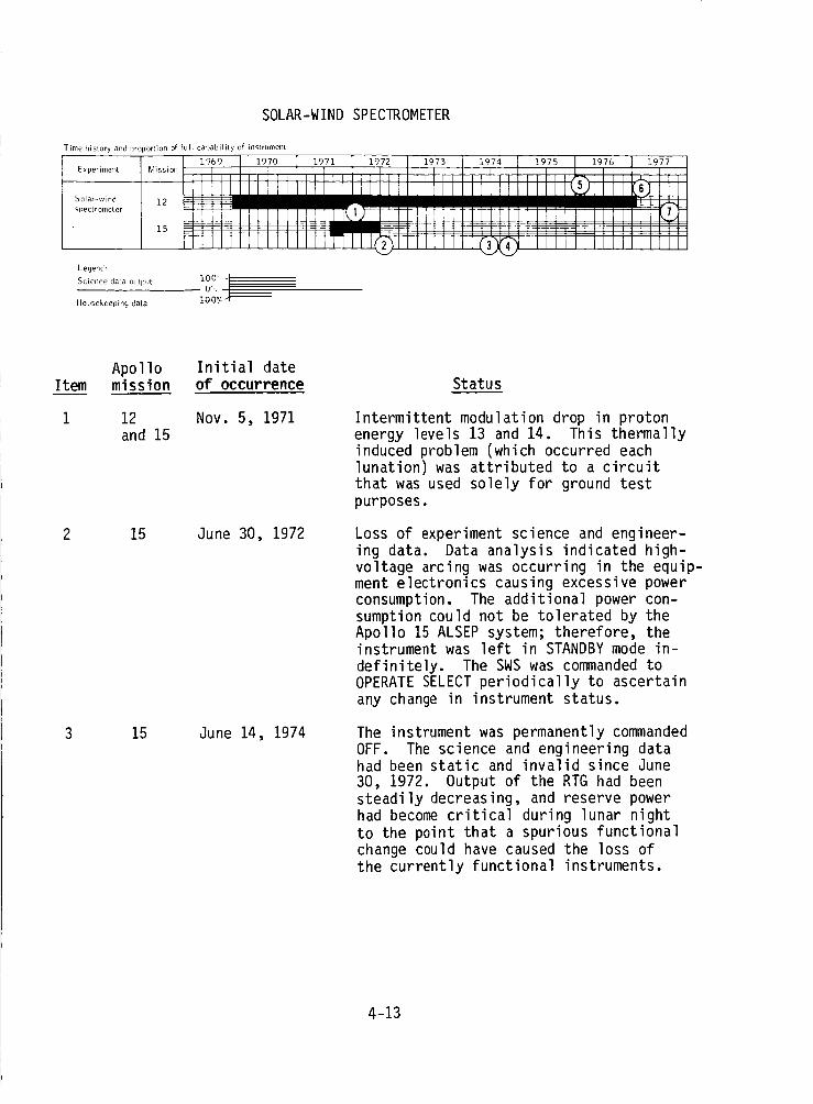
SOLAR-WINDSPECTROMETER
Time history and 1_Ol)ortion of full cal_ability of instrument
Exl)eriment
Solar-wind
s_)ectr omet er
Legend:
Science data OUtl)[lt
Housekeeping data
Item
i
Apollo Initial datemission of occurrence
12 Nov. 5, 1971and 15
2 15 June 30, 1972
3 15 June 14, 1974
Status
Intermittent modulation drop in protonenergy levels 13 and 14. This thermallyinduced problem (which occurred eachlunation) was attributed to a circuitthat was used solely for ground testpurposes.
Loss of experiment science and engineer-ing data. Data analysis indicated high-voltage arcing was occurring in the equip-ment electronics causing excessive powerconsumption. The additional power con-sumption could not be tolerated by theApollo 15 ALSEP system; therefore, theinstrument was left in STANDBY mode in-definitely. The SWS was commanded toOPERATE SELECT periodically to ascertainany change in instrument status.
The instrument was permanently commandedOFF. The science and engineering datahad been static and invalid since June30, 1972. Output of the RTG had beensteadily decreasing, and reserve powerhad become critical during lunar nightto the point that a spurious functionalchange could have caused the loss ofthe currently functional instruments.
4-13
SOLAR-WINDSPECTROMETER- Concluded
Item
4
Apollomission
15
12
12
12and 15
Initial dateof occurrence Status
July 3, 1974
Mar. 3, 1976
Jan. 15, 1977
Sept. 30, 1977
The instrument was commanded ON duringreal-time support on July 3, July 29,and Sept. 3, 1974. No scientific orengineering data were received in theALSEP downlink. Reserve power changewas 6.00 W on July 29, but was negli-gible for the other checks.
A spurious functional command to ON wasreceived by the instrument on Jan. 25,1975, resulting in a 3.9-W reserve powerdrain. The instrument was commandedto STANDBY (no reserve power change)and then to OFF, and the reserve powerincreased 3.9 W.
A spurious functional command to STANDBYPOWERON was received by the instrumenton Sept. 15, 1975, resulting in a 4-Wreserve power drain. The decrease inreserve power was attributed to thestandby heater turning on. The instru-ment was commanded to OFF and the reserve
power increased 4 W.
A spurious functional command to ON wasreceived by the instrument on Jan. 31,1976. The experiment was commanded toOFF by the Guam Tracking Station; anincrease or decrease in reserve powerwas not observed.
The instrument was being turned to STAND-BY during the lunar night to providemore heat in the central station PSEelectronics to avoid the PSE analog-to-digital converter anomaly.
Instrument turned off to increase poweravailable for central-station thermalcontrol.
No change in status when ALSEP programwas terminated.
4-14
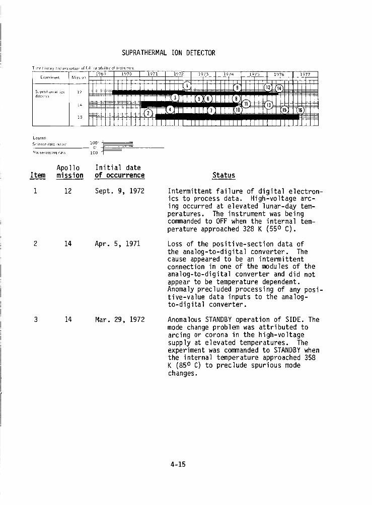
SUPRATHERMALIONDETECTOR
T ime history and proportion of full capability of iIIstrument
:, _111
SLg)rathernlal io,1 12 --2 (i_11 I i I II I I_etecto, , , I_- .8
14 --_ _
]973
Legend:
Science data OlRpLit
Housekeeping data
i00"
O' .___i00
Apollo Initial dateItem mission of occurrence Status
1 12 Sept. 9, 1972 Intermittent failure of digital electron-ics to process data. High-voltage arc-ing occurred at elevated lunar-day tem-peratures. The instrument was beingcommanded to OFF when the internal tem-perature approached 328 K (55 o C).
2 14 Apr. 5, 1971 Loss of the positive-section data ofthe analog-to-digital converter. Thecause appeared to be an intermittentconnection in one of the modules of theanalog-to-digital converter and did notappear to be temperature dependent.Anomaly precluded processing of any posi-tive-value data inputs to the analog-to-digital converter.
3 14 Mar. 29, 1972 Anomalous STANDBY operation of SIDE. Themode change problem was attributed toarcing or corona in the high-voltagesupply at elevated temperatures. Theexperiment was commanded to STANDBY whenthe internal temperature approached 358K (85 o C) to preclude spurious modechanges.
4-15

SUPRATHERMALIONDETECTOR- Continued
Item
4
Apollomission
15
14
14
15
Initial dateof occurrence Status
May 1, 1972
Apr. 14, 1973
Aug. 8, 1973
Sept. 13, 1973
Full instrument operation instituted.Prior to Oct. 20, 1972, the Apollo 15SIDE was cycled to STANDBY duringlunar day because of previous problemswith the Apollo 12 SIDE. Based on dataaccumulated since deployment, it wasdecided to leave the instrument ON forthe complete lunation.
Anomalous STANDBY operation of SIDE.Subsequent to Apr. 1973, the instrumenthad gone from OPERATE to STANDBY withoutground command at (or shortly after)the sunrise terminator crossing. Thesuspected cause was circuit breaker ac-tion in response to a SIDE current inexcess of that required to trip thebreaker. Data were obtained duringlunar night when the instrument was ON.The instrument was permitted to switchitself from ON to STANDBY at sunriseterminator without commanding.
There was no indication of STANDBY powerON or operating power OFF through theconsole monitor lights or the high-speedprinter data. Analysis indicated thatthe fuse opened in the STANDBY powerline; thus, STANDBY operation was nowequivalent to OFF.
Cyclic commanding required to precludespurious mode changes above 358 o K(85 o C). Internal high-voltage arcingcaused -3.5-kV power supply to trip OFF.The instrument was cycled to STANDBYduring lunar day to preclude arcing.
4-16
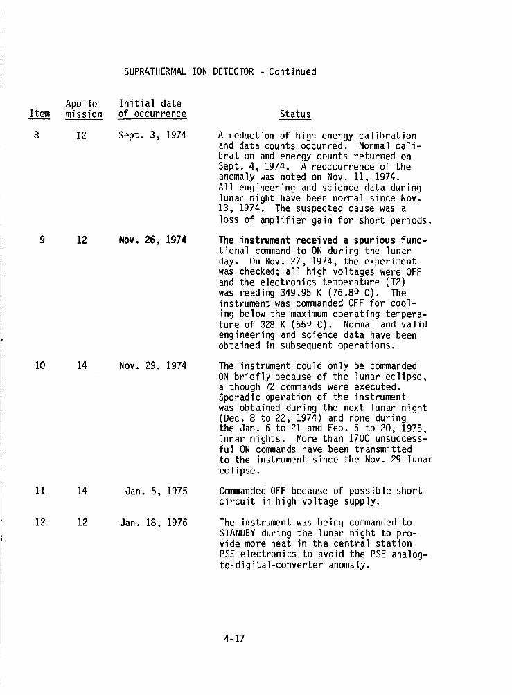
SUPRATHERMALIONDETECTOR- Continued
Item
8
9
10
11
12
Apollomission
12
12
14
14
12
Initial dateof occurrence Status
Sept. 3, 1974
NOV. 26, 1974
Nov. 29, 1974
Jan. 5, 1975
Jan. 18, 1976
A reduction of high energy calibrationand data counts occurred. Normal cali-bration and energy counts returned onSept. 4, 1974. A reoccurrence of theanomaly was noted on Nov. 11, 1974.All engineering and science data duringlunar night have been normal since Nov.13, 1974. The suspected cause was aloss of amplifier gain for short periods.
The instrument received a spurious func-
tional command to ON during the lunarday. On Nov. 27, 1974, the experiment
was checked; all high voltages were OFFand the electronics temperature (T2)
was reading 349.95 K (76.80 C). Theinstrument was commanded OFF for cool-
ing below the maximum operating tempera-ture of 328 K (550 C). Normal and validengineering and science data have been
obtained in subsequent operations.
The instrument could only be commandedON briefly because of the lunar eclipse,although 72 commands were executed.Sporadic operation of the instrumentwas obtained during the next lunar night(Dec. 8 to 22, 1974) and none duringthe Jan. 6 to 21 and Feb. 5 to 20, 1975,lunar nights. More than 1700 unsuccess-ful ON commands have been transmittedto the instrument since the Nov. 29 lunareclipse.
Commanded OFF because of possible shortcircuit in high voltage supply.
The instrument was being commanded to
STANDBY during the lunar night to pro-vide more heat in the central station
PSE electronics to avoid the PSE analog-to-digital-converter anomaly.
4-17

SUPRATHERMALIONDETECTOR- Concluded
Item
13
14
15
16
Apollomission
14
12
15
15
Initial dateof occurrence Status
Feb. 19, 1976
May 3, 1976
Aug. 26, 1976
Mar. 12, 1977
With the return of uplink to the Apollo14 central station, the experiment statuswas unknown. Experiment was commandedOFF as extra protection from possiblehigh voltage short.
Commanded OFF.
Operating in the RESET SIDE mode; framecounter at 39; 3.5-kV Channeltron inHIGH VOLTAGE.
Commanded OFF.
4-18
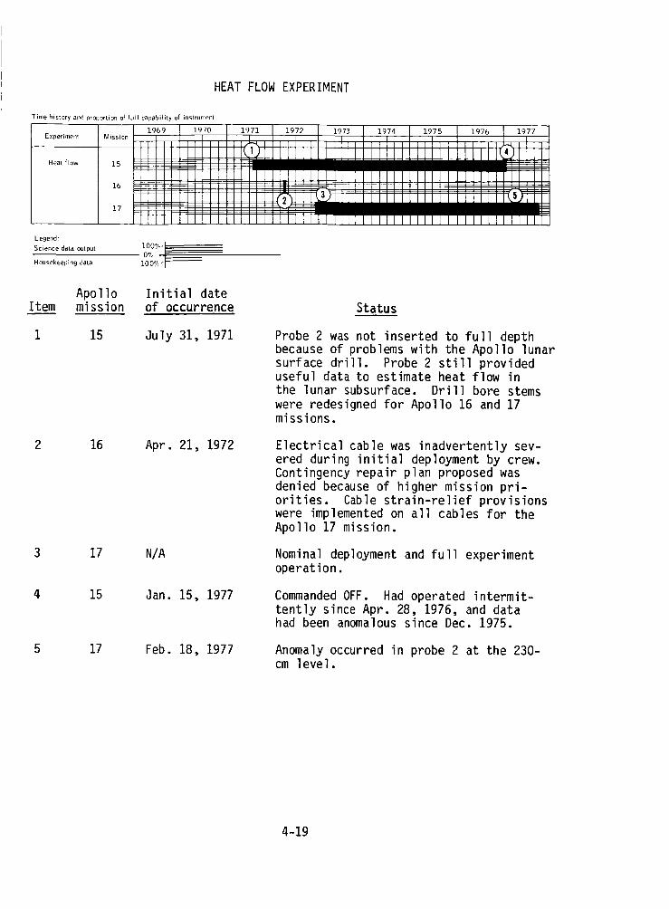
HEATFLOWEXPERIMENT
Time history and proportion of full capability of instrument
Experiment
Heat flow
Legend:
Science data mJtput
Housekeeping data
Mission151716 __ lC6% __1_7_ _' ' ':iJ_'1971 ! 1_I_72__iii i m"9,7 i im 1197,_ ! _;_ Ii ]9_ P7
Apollo Initial dateItem mission of occurrence Status
I 15 July 31, 1971 Probe 2 was not inserted to full depthbecause of problems with the Apollo lunarsurface drill. Probe 2 still provideduseful data to estimate heat flow inthe lunar subsurface. Drill bore stemswere redesigned for Apollo 16 and 17missions.
2 16 Apr. 21, 1972
3 17 N/A
Electrical cable was inadvertently sev-ered during initial deployment by crew.Contingency repair plan proposed wasdenied because of higher mission pri-orities. Cable strain-relief provisionswere implemented on all cables for theApollo 17 mission.
Nominal deployment and full experimentoperation.
4 15 Jan. 15, 1977 Commanded OFF. Had operated intermit-tently since Apr. 28, 1976, and datahad been anomalous since Dec. 1975.
5 17 Feb. 18, 1977 Anomaly occurred in probe 2 at the 230-cm level.
4-19
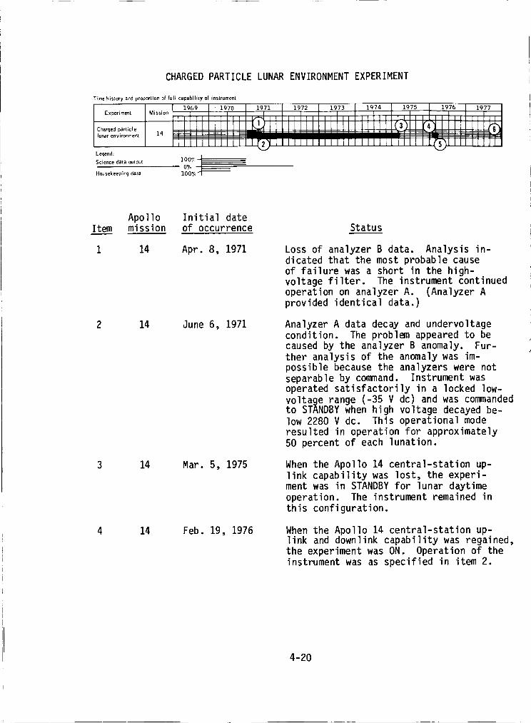
CHARGED PARTICLE LUNAR ENVIRONMENT EXPERIMENT
Time history and proportion of full capability of instrument
Experiment
Charged particle
lunar environment
Legend:
Science data output
Housekeeping data
Item
4
Apollomission
14
14
14
14
Initial dateof occurrence
Apr. 8, 1971
June 6, 1971
Mar. 5, 1975
Feb. 19, 1976
Status
Loss of analyzer B data. Analysis in-dicated that the most probable cause
of failure was a short in the high-voltage filter. The instrument continuedoperation on analyzer A. (Analyzer Aprovided identical data.)
Analyzer A data decay and undervoltagecondition. The problem appeared to be
caused by the analyzer B anomaly. Fur-ther analysis of the anomaly was im-possible because the analyzers were not
separable by command. Instrument wasoperated satisfactorily in a locked low-
voltage range (-35 V dc) and was commandedto STANDBY when high voltage decayed be-
low 2280 V dc. This operational moderesulted in operation for approximately
50 percent of each lunation.
When the Apollo 14 central-station up-link capability was lost, the experi-
ment was in STANDBY for lunar daytime
operation. The instrument remained inthis configuration.
When the Apollo 14 central-station up-link and downlink capability was regained,the experiment was ON. Operation of theinstrument was as specified in item 2.
4-20

CHARGEDPARTICLELUNARENVIRONMENTEXPERIMENT- Concluded
Item
5
6
Apollo Initial datemission of occurrence Status
14 Mar. 17, 1976
14 Sept. 30, 1977
When the Apollo 14 central-station up-link and downlink capability was lost,the experiment was in STANDBY for lunardaytime operation. The instrument re-
mained in this configuration. (NOTE:Operation of the CPLEE until ALSEP ter-
mination was related to the Apollo 14central station anomaly. The subsectionentitled "Central Station Electronics"
gives the CPLEE configuration each timethat the signal was lost and regained.)
At the end of termination test, instru-ment was configured to STANDBY.
4-21
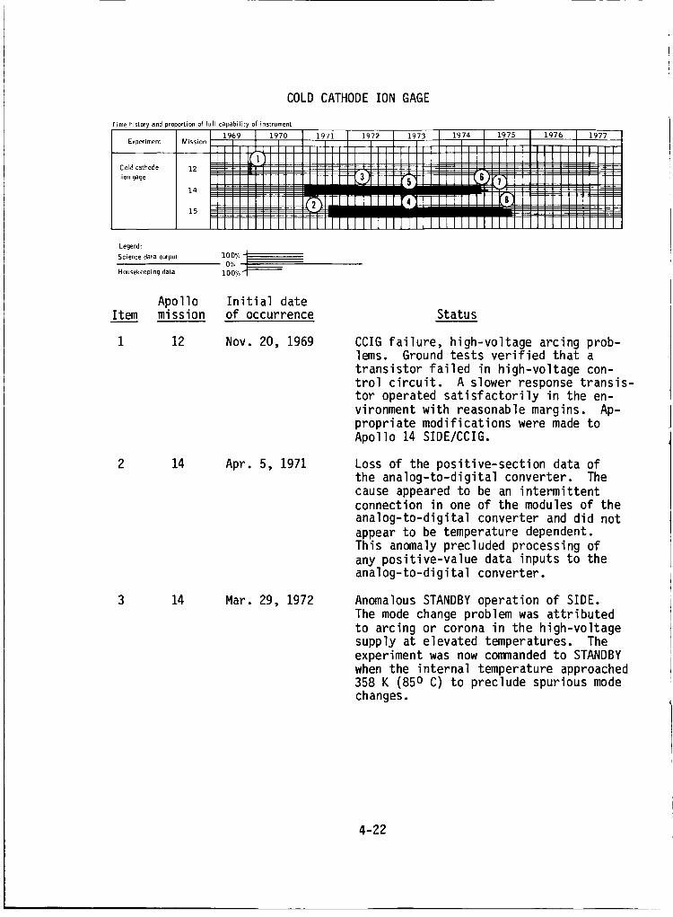
COLDCATHODEIONGAGE
Time history and proportion of Full capability of instrument
• 96( L 197'1
Experiment Mission 1 = __) ]I_ _ _1 _i i!
Cold cathode 12 : : : : : :
ion gage 14:15 ;_-_=: ::__
Ic
I
w,m
19f! L97 I
NNI• , , ,
Legend:
Science data output 100% -'
0% ,__
Housekeeping data 100o/ 11 --
ApolloItem mission
Initial dateof occurrence Status
1 12 Nov. 20, 1969 CCIG failure, high-voltage arcing prob-lems. Ground tests verified that a
transistor failed in high-voltage con-
trol circuit. A slower response transis-tor operated satisfactorily in the en-
vironment with reasonable margins. Ap-propriate modifications were made toApollo 14 SIDE/CCIG.
2 14 Apr. 5, 1971 Loss of the positive-section data ofthe analog-to-digital converter. Thecause appeared to be an intermittentconnection in one of the modules of the
analog-to-digital converter and did not
appear to be temperature dependent.
This anomaly precluded processing ofany positive-value data inputs to theanalog-to-digital converter.
3 14 Mar. 29, 1972 Anomalous STANDBY operation of SIDE.
The mode change problem was attributed
to arcing or corona in the high-voltagesupply at elevated temperatures. The
experiment was now commanded to STANDBY
when the internal temperature approached358 K (850 C) to preclude spurious modechanges.
4-22

COLDCATHODEIONGAGE- Concluded
Item
4
6
Apollomission
15
14
14
14
15
Initial dateof occurrence Status
Feb. 22, 1973
Apr. 8, 1973
Nov. 29, 1974
Jan. 5, 1975
July 18, 1975
Intermittent science data. Preliminaryanalysis indicated that the most prob-able cause was one of the 15 relays.
These reed relays performed functionsthat controlled the CCIG calibration
currents, the ranging and gain change
functions, and grounding the instrumentduring calibration. At this time, no
plans existed for continued investiga-tion of the anomaly, because the scien-tific data were usable when obtained.
See item 6 of the status report on theSuprathermal Ion Detector Experiment.
See item 11 of the status report on theSuprathermal Ion Detector Experiment.
Commanded OFF.
CCIG failure; high voltage was off andcould not be commanded ON.
4-23
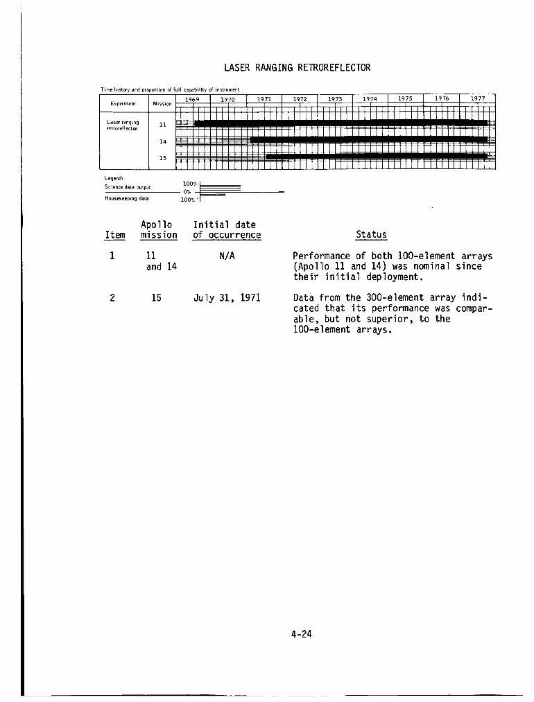
LASERRANGINGRETROREFLECTOR
Time history and proportion of full capability of instrument
9_ .9Experiment Mission
Laser ranging 11 i _-_ • •
retroreHector -- --
14 _- _
15 _
Legend:
Science data output
Housekeeping data
lO0%-J
z'_'m J 197:_ [ i97, I 197!
i m |!mm_m , , ,In,
i [] iii
I
Item
1
Apollomission
11and 14
2 15
Initial dateof occurrence
N/A
July 31, 1971
Status
Performance of both lO0-element arrays(Apollo 11 and 14) was nominal since
their initial deployment.
Data from the 300-element array indi-
cated that its performance was compar-
able, but not superior, to thelO0-element arrays.
4-24
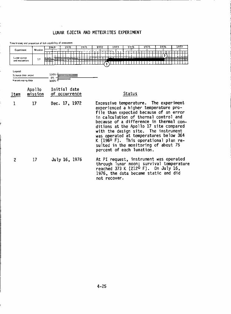
LUNAREJECTAANDMETEORITESEXPERIMENT
Time history and proportion of full capability of instrument
Experiment
Lunar ejecta
and meteorites
r egend:
Science data output 100% ]
0%
Housekeeping data 100O/o
Apollo Initial dateItem mission of occurrence
1 17 Dec. 17, 1972
2 17 July 16, 1976
Status
Excessive temperature. The experiment
experienced a higher temperature pro-file than expected because of an errorin calculation of thermal control andbecause of a difference in thermal con-
ditions at the Apollo 17 site compared
with the design site. The instrumentwas operated at temperatures below 364K (196o F). This operational plan re-
sulted in the monitoring of about 75percent of each lunation.
At PI request, instrument was operatedthrough lunar noon; survival temperaturereached 373 K (2120 F). On July 16,
1976, the data became static and didnot recover.
4-25
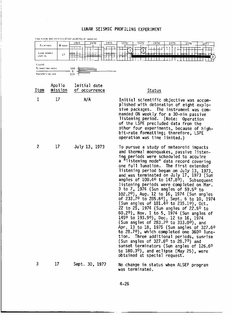
LUNAR SEISMIC PROFILING EXPERIMENT
T ime history and prol)ortion of full capability of instrument
I I 1969 I 1970 l 1971 I 1972 I 1973 I 1974 I 1975 I 1976 1977 |
L Ll_lar seismic
pro[ i l illg 17 - "
Legend:
Sci ..... data output 170 4
Housekeeping data 1000 El]--
Item
1
Apollo Initial datemission of occurrence Status
17 NIA
2 17 July 13, 1973
3 17 Sept. 30, 1977
Initial scientific objective was accom-
plished with detonation of eight explo-sive packages. The instrument was com-
manded ON weekly for a 30-min passivelistening period. (Note: Operationof the LSPE precluded data from the
other four experiments, because of high-bit-rate formatting; therefore, LSPE
operation was time limited.)
To pursue a study of meteoroid impactsand thermal moonquakes, passive listen-ing periods were scheduled to acquire
a "listening mode" data record coveringone full lunation. The first extended
listening period began on July 13, 1973,and was terminated on July 17, 1973 (Sun
angles of 100.4o to 147.8o). Subsequentlistening periods were completed on Mar.3 to 7, 1974 (Sun angles of 59.50 to
102.2°), Aug. 12 to 16, 1974 (Sun angles
of 233.70 to 285.60), Sept. 6 to 10, 1974(Sun angles of 181.4o to 235.1o), Oct.
22 to 25, 1974 (Sun angles of 22.50 to
60.20), Nov. 1 to 5, 1974 (Sun angles of145o to 193.9o), Dec. 12 to 16, 1974
(Sun angles of 283.70 to 333.00), and
Apr. 13 to 18, 1975 (Sun angles of 327.60to 28.70), which completed one 3600 luna-
tion. Three additional periods, sunrise(Sun angles of 327.6 o to 28.70 ) and
sunset terminators (Sun angles of 126.60
to 180.3°), and eclipse (May 25), wereobtained at special request.
No change in status when ALSEP programwas terminated.
4-26
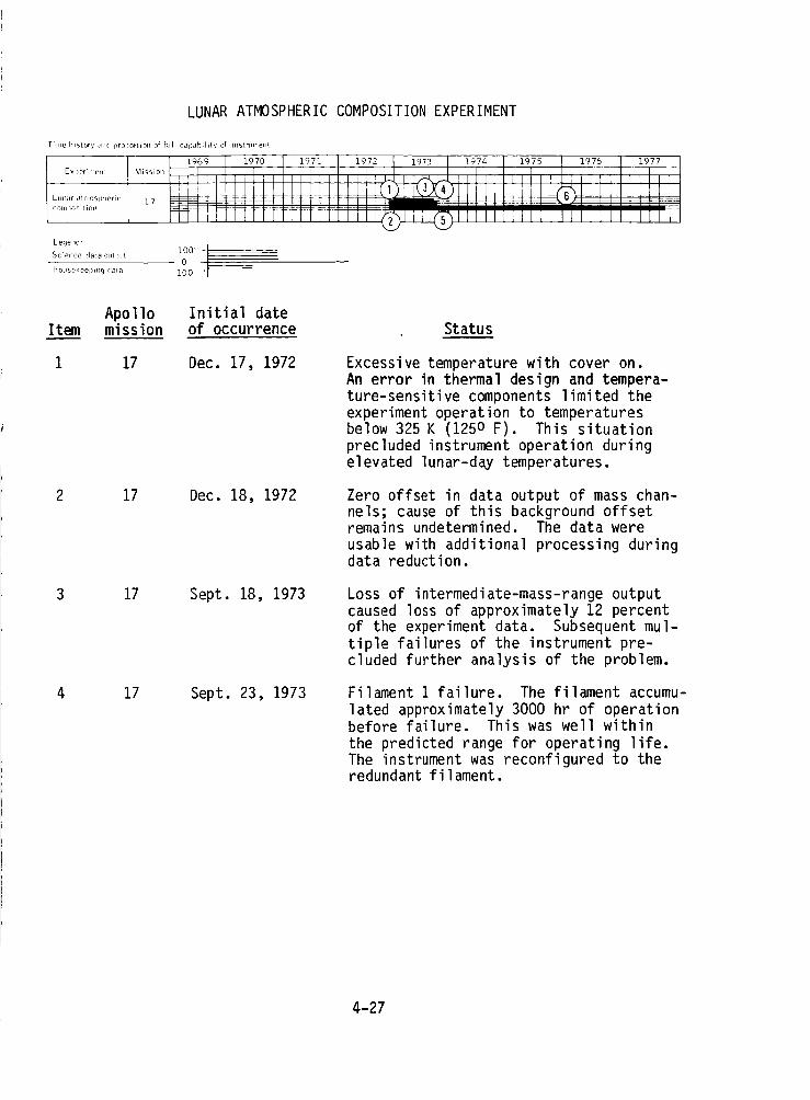
LUNAR ATMOSPHERIC COMPOSITION EXPERIMENT
Time history and i)rollor[iOll o_ full caF)ability of instrument
Exl)erilnetR
ktlllar atlllOSpheric
COml_O_tioll
Legend:
_cience data oL_tl)ut 100 -t0 [Housekeel)in 9 data 100 ' --
Item
I
Apollomission
17
2 17
3 17
4 17
Initial dateof occurrence
Dec. 17, 1972
Dec. 18, 1972
Sept. 18, 1973
Sept. 23, 1973
Status
Excessive temperature with cover on.An error in thermal design and tempera-ture-sensitive components limited theexperiment operation to temperaturesbelow 325 K (125 o F). This situationprecluded instrument operation duringelevated lunar-day temperatures.
Zero offset in data output of mass chan-nels; cause of this background offsetremains undetermined. The data wereusable with additional processing duringdata reduction.
Loss of intermediate-mass-range outputcaused loss of approximately 12 percentof the experiment data. Subsequent mul-tiple failures of the instrument pre-cluded further analysis of the problem.
Filament 1 failure. The filament accumu-lated approximately 3000 hr of operationbefore failure. This was well withinthe predicted range for operating life.The instrument was reconfigured to theredundant filament.
4-27

LUNARATMOSPHERICCOMPOSITIONEXPERIMENT- Concluded
Item
5
Apollomission
17
17
Initial dateof occurrence Status
Oct. 17, 1973
Jan. 18, 1974 toFeb. 26, 1976
Loss of science data. Preliminary re-sults of trouble-shooting and analysisindicated that the multiplier high-voltagepower supply apparently failed. At thattime, the instrument was being cycled fromON to OFF to maintain the electronics tem-perature below the previously established325 K (125 o F) limit, while future trouble-shooting or termination of instrumentoperation was considered.
A total of nine operational checks wereperformed, following both "bakeout" and"cold soak," in attempts to regain theproper voltage, but each attempt wasunsuccessful.
4-28
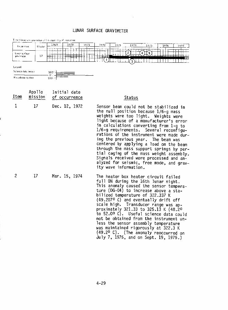
LUNARSURFACEGRAVIMETER
Time history and proportion of full cal)abiiity of instrument
Experiment
Ltnlar surface
gravimeter
Legend:
Science data oULpLIt
Housekeeping data
_3 2 1974 4 I_75 1976 1977
i00' , |
Item
1
Apollo Initial datemission of occurrence Status
17 Dec. 12, 1972
2 17 Mar. 15, 1974
Sensor beam could not be stabilized inthe null position because 1/6-g massweights were too light. Weights werelight because of a manufacturer's errorin calculations converting from 1-g to1/6-g requirements. Several reconfigu-rations of the instrument were made dur-ing the previous year. The beam wascentered by applying a load on the beamthrough the mass support springs by par-tial caging of the mass weight assembly.Signals received were processed and an-alyzed for seismic, free mode, and grav-ity wave information.
The heater box heater circuit failedfull ON during the 16th lunar night.This anomaly caused the sensor tempera-ture (DG-04) to increase above a sta-bilized temperature of 322.337 K(49.207 o C) and eventually drift offscale high. Transducer range was ap-proximately 321.33 to 325.13 K (48.2 oto 52.0o C). Useful science data couldnot be obtained from the instrument un-less the sensor assembly temperaturewas maintained rigorously at 322.3 K(49.2 o C). (The anomaly reoccurred onJuly 7, 1975, and on Sept. 19, 1975.)
4-29
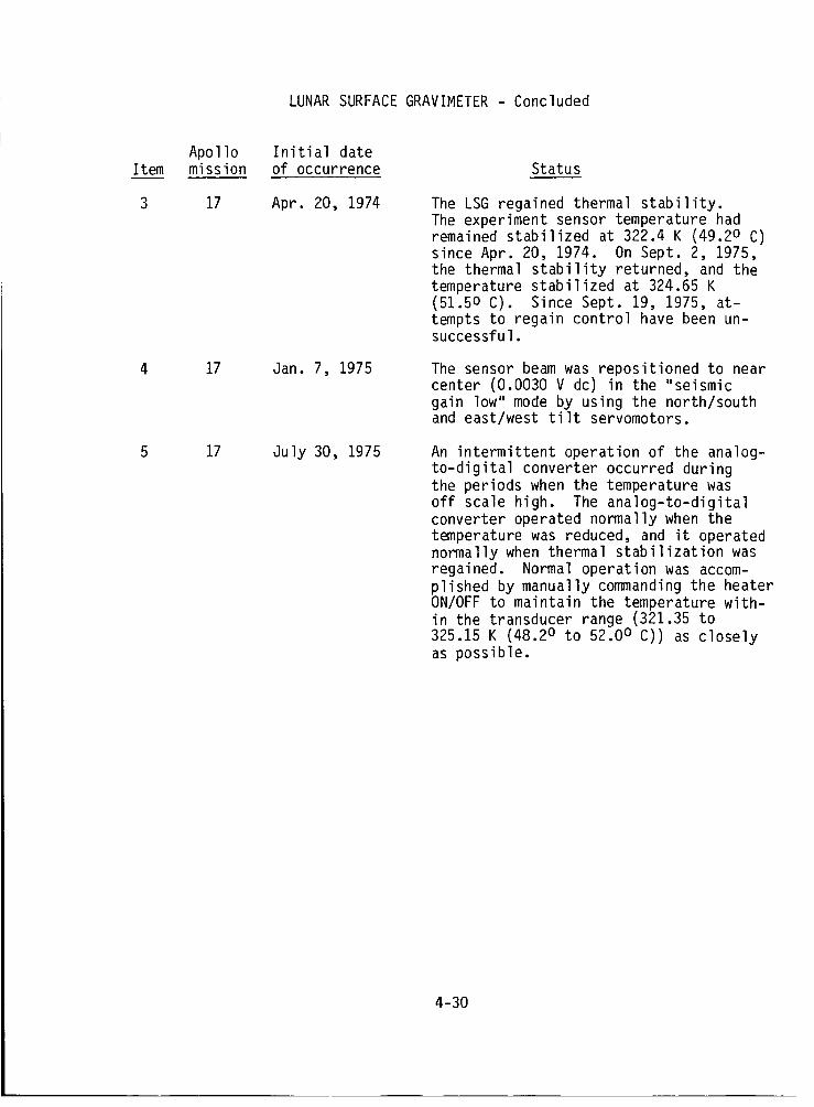
LUNARSURFACEGRAVIMETER- Concluded
Item
3
Apollomission
17
17
17
Initial dateof occurrence Status
Apr. 20, 1974
Jan. 7, 1975
July 30, 1975
The LSG regained thermal stability.The experiment sensor temperature hadremained stabilized at 322.4 K (49.2 o C)since Apr. 20, 1974. On Sept. 2, 1975,the thermal stability returned, and thetemperature stabilized at 324.65 K(51.5o C). Since Sept. 19, 1975, at-tempts to regain control have been un-successful.
The sensor beam was repositioned to nearcenter (0.0030 V dc) in the "seismicgain low" mode by using the north/southand east/west tilt servomotors.
An intermittent operation of the analog-to-digital converter occurred duringthe periods when the temperature wasoff scale high. The analog-to-digitalconverter operated normally when thetemperature was reduced, and it operatednormally when thermal stabilization wasregained. Normal operation was accom-plished by manually commanding the heaterON/OFF to maintain the temperature with-in the transducer range (321.35 to325.15 K (48.2 o to 52.0 o C)) as closelyas possible.
4-30
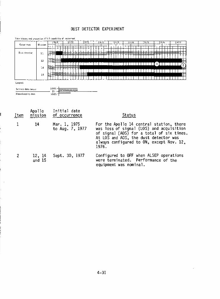
DUSTDETECTOREXPERIMENT
Time history and proportion of full capability of instrument
195G
E )<'per imerit
Dust detector
Legend:
Science data output
Housekeeping data
Mission-
11
12
14
15
L9
I I
R I I
I
Item
i
Apollomission
14
12, 14and 15
Initial dateof occurrence
Mar. 1, 1975to Aug. 7, 1977
Sept. 30, 1977
Status
For the Apollo 14 central station, therewas loss of signal (LOS) and acquisitionof signal (AOS) for a total of six times.At LOS and AOS, the dust detector wasalways configured to ON, except Nov. 12,1976.
Configured to OFF when ALSEP operationswere terminated. Performance of theequipment was nominal.
4-31
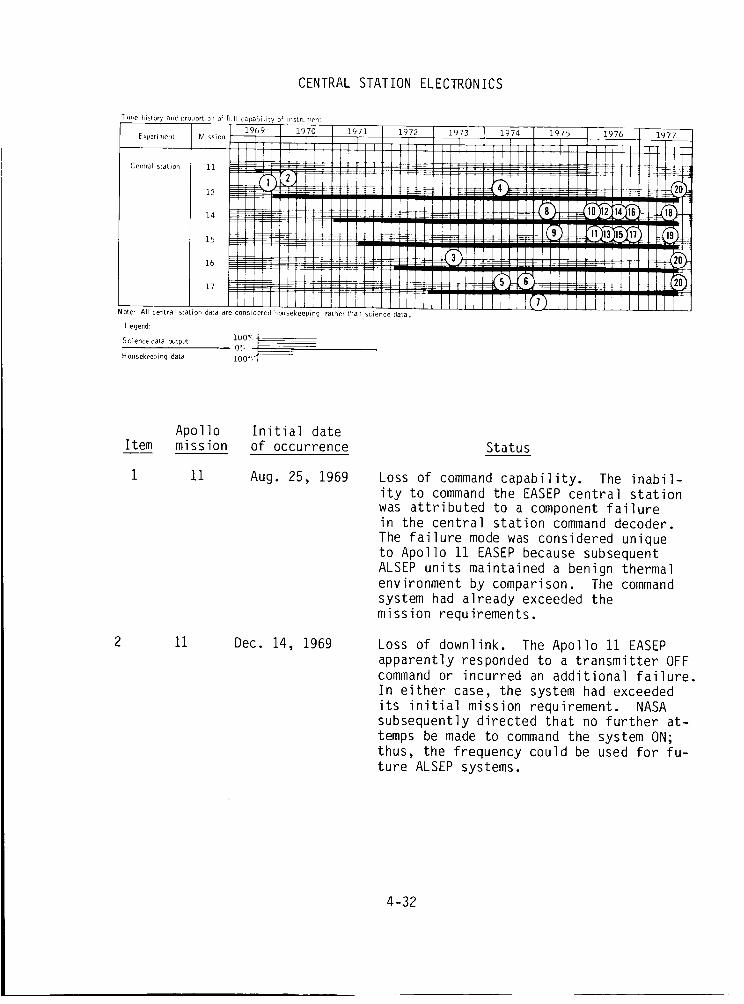
CENTRALSTATIONELECTRONICS
Time history and ilroportio, of full capability of instroment
.9 I .9E xperi r'lent M i ssi on
i
Central station 11
12 ---
14 _
_3
15 _ _
16 Z _
17 -- _
L9 I ]
Note" All central station data are considered housekeeping rather Lhan science data.
LegeNd:
Science data _Jtput 100_
Housekeeping data 100°',
]
_4
i
F_
I
I
L977
i , ,.n*
Apollo Initial dateItem mission of occurrence
1 11 Aug. 25, 1969
11 Dec. 14, 1969
Status
Loss of command capability. The inabil-ity to command the EASEP central stationwas attributed to a component failurein the central station command decoder.The failure mode was considered uniqueto Apollo ii EASEP because subsequentALSEP units maintained a benign thermalenvironment by comparison. The commandsystem had already exceeded themission requirements.
Loss of downlink. The Apollo 11 EASEPapparently responded to a transmitter OFFcommand or incurred an additional failure.In either case, the system had exceededits initial mission requirement. NASAsubsequently directed that no further at-temps be made to command the system ON;thus, the frequency could be used for fu-ture ALSEP systems.
4-32
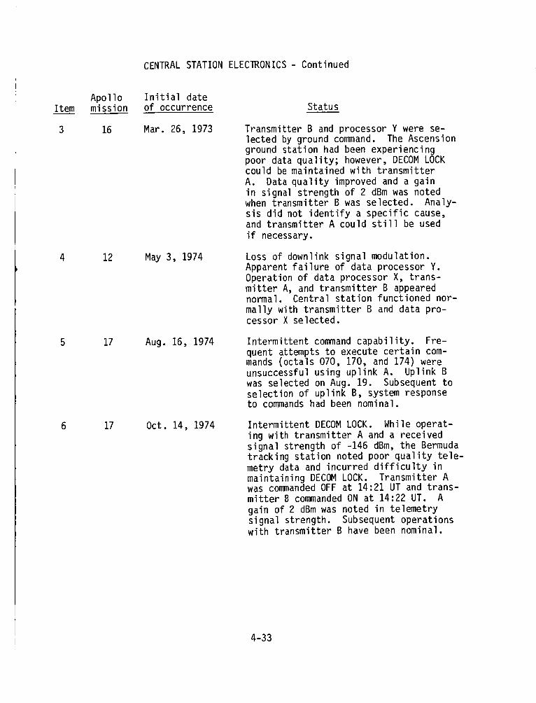
CENTRALSTATIONELECTRONICS- Continued
Item
3
4
Apollomission
16
12
17
17
Initial dateof occurrence Status
Mar. 26, 1973
May 3, 1974
Aug. 16, 1974
Oct. 14, 1974
Transmitter B and processor Y were se-lected by ground command. The Ascensionground station had been experiencing
poor data quality; however, DECOM LOCKcould be maintained with transmitter
A. Data quality improved and a gain
in signal strength of 2 dBm was notedwhen transmitter B was selected. Analy-
sis did not identify a specific cause,and transmitter A could still be used
if necessary.
Loss of downlink signal modulation.Apparent failure of data processor Y.
Operation of data processor X, trans-mitter A, and transmitter B appearednormal. Central station functioned nor-
mally with transmitter B and data pro-cessor X selected.
Intermittent command capability. Fre-
quent attempts to execute certain com-mands (octals 070, 170, and 174) wereunsuccessful using uplink A. Uplink B
was selected on Aug. 19. Subsequent toselection of uplink B, system responseto commands had been nominal.
Intermittent DECOM LOCK. While operat-
ing with transmitter A and a receivedsignal strength of -146 dBm, the Bermudatracking station noted poor quality tele-
metry data and incurred difficulty inmaintaining DECOM LOCK. Transmitter Awas commanded OFF at 14:21 UT and trans-mitter B commanded ON at 14:22 UT. A
gain of 2 dBm was noted in telemetry
signal strength. Subsequent operationswith transmitter B have been nominal.
4-33
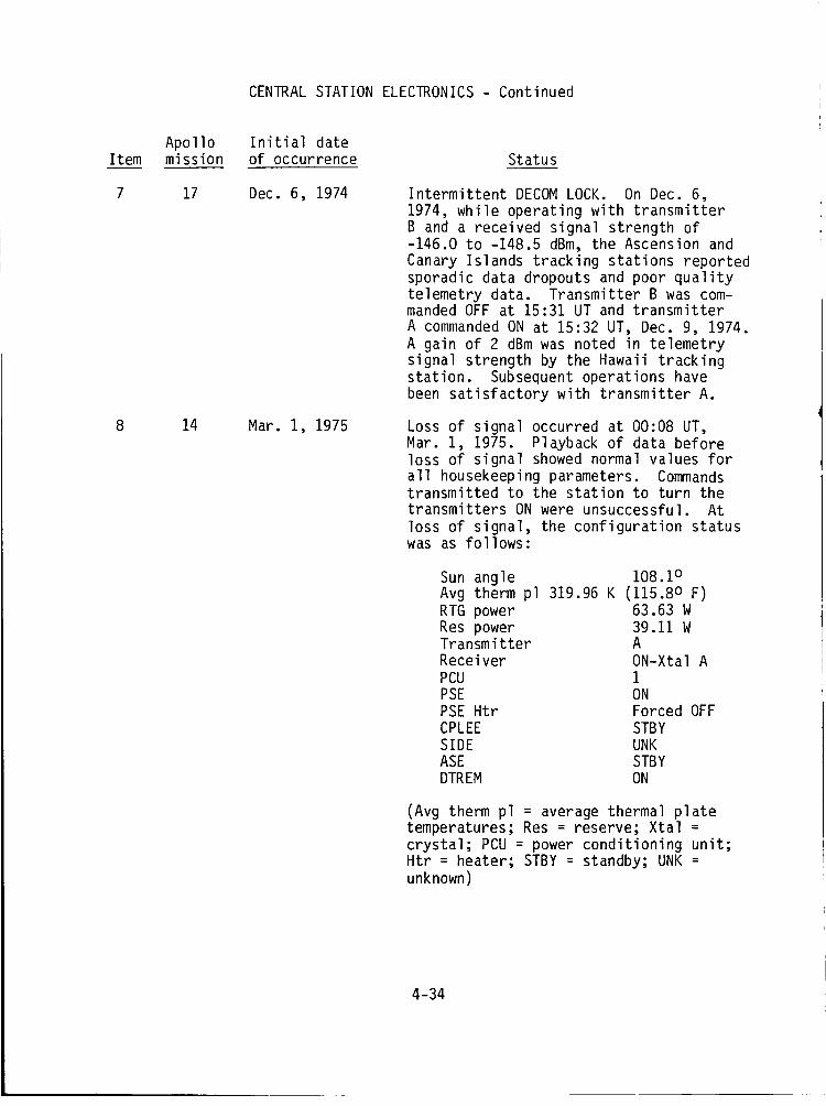
CENTRAL STATION ELECTRONICS - Continued
Item
7
Apollomission
17
14
Initial dateof occurrence Status
Dec. 6, 1974
Mar. 1, 1975
Intermittent DECOMLOCK. On Dec. 6,1974, while operating with transmitterB and a received signal strength of-146.0 to -148.5 dBm, the Ascension andCanary Islands tracking stations reportedsporadic data dropouts and poor qualitytelemetry data. Transmitter B was com-manded OFF at 15:31 UT and transmitterA commanded ON at 15:32 UT, Dec. 9, 1974.A gain of 2 dBm was noted in telemetrysignal strength by the Hawaii trackingstation. Subsequent operations havebeen satisfactory with transmitter A.
Loss of signal occurred at 00:08 UT,Mar. 1, 1975. Playback of data beforeloss of signal showed normal values forall housekeeping parameters. Commandstransmitted to the station to turn thetransmitters ON were unsuccessful. Atloss of signal, the configuration statuswas as follows:
Sun angle 108.1 oAvg therm pl 319.96 K (115.8 o F)RTG power 63.63 WRes power 39.11WTransmitter AReceiver ON-Xtal APCU iPSE ONPSE Htr Forced OFFCPLEE STBYSIDE UNKASE STBYDTREM ON
(Avg therm pl = average thermal platetemperatures; Res = reserve; Xtal =crystal; PCU = power conditioning unit;Htr = heater; STBY : standby; UNK =unknown)
4-34
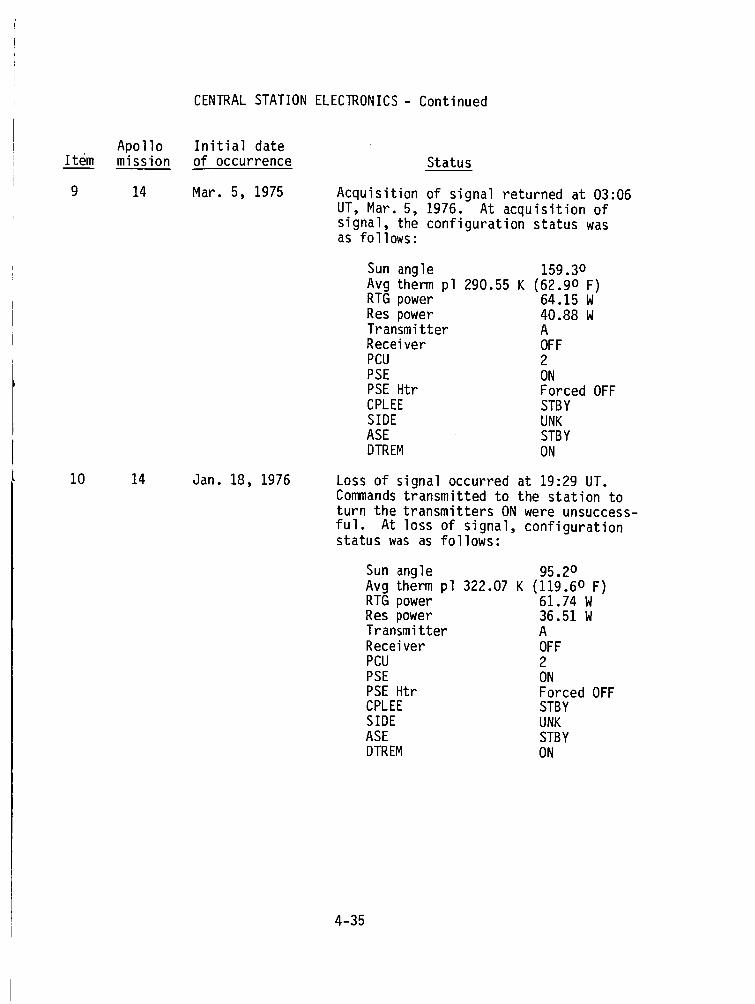
CENTRALSTATIONELECTRONICS- Continued
Item
9
I0
Apollo Initial datemission of occurrence Status
14
14
Mar. 5, 1975
Jan. 18, 1976
Acquisition of signal returned at 03:06UT, Mar. 5, 1976. At acquisition ofsignal, the configuration status wasas follows:
Sun angle 159.3 oAvg therm pl 290.55 K (62.9 o F)RTG power 64.15 WRes power 40.88 WTransmitter AReceiver OFFPCU 2PSE ONPSE Htr Forced OFFCPLEE STBYSIDE UNKASE STBYDTREM ON
Loss of signal occurred at 19:29 UT.Commands transmitted to the station toturn the transmitters ON were unsuccess-
ful. At loss of signal, configurationstatus was as follows:
Sun angle 95.2 oAvg therm pl 322.07 K (119.6 o F)RTG power 61.74 WRes power 36.51WTransmitter AReceiver OFFPCU 2PSE ONPSE Htr Forced OFFCPLEE STBYSIDE UNKASE STBYDTREM ON
4-35
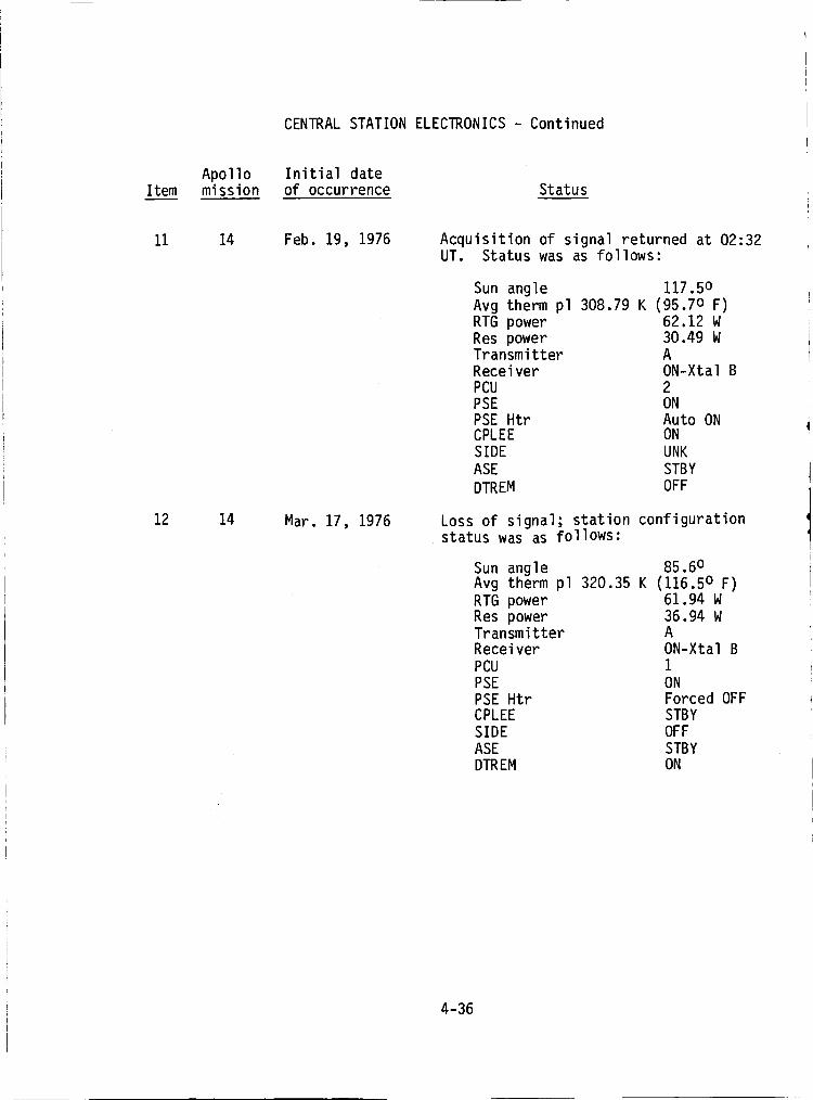
CENTRAL STATION ELECTRONICS - Continued
ItemApollomission
Initial dateof occurrence Status
11
12
14
14
Feb. 19, 1976
Mar. 17, 1976
Acquisition of signal returned at 02:32UT. Status was as follows:
Sun angle 117.5oAvg therm pl 308.79 K (95.7o F)
RTG power 62.12 WRes power 30.49 WTransmitter AReceiver ON-Xtal B
PCU 2PSE ON
PSE Htr Auto ONCPLEE ON
SIDE UNK
ASE STBY
DTREM OFF
Loss of signal; station configurationstatus was as follows:
Sun angle 85.6oAvg therm pl 320.35 K (116.5o F)
RTG power 61.94 WRes power 36.94 WTransmitter AReceiver ON-Xtal B
PCU 1
PSE ONPSE Htr Forced OFFCPLEE STBY
SIDE OFF
ASE STBYDTREM ON
4-36
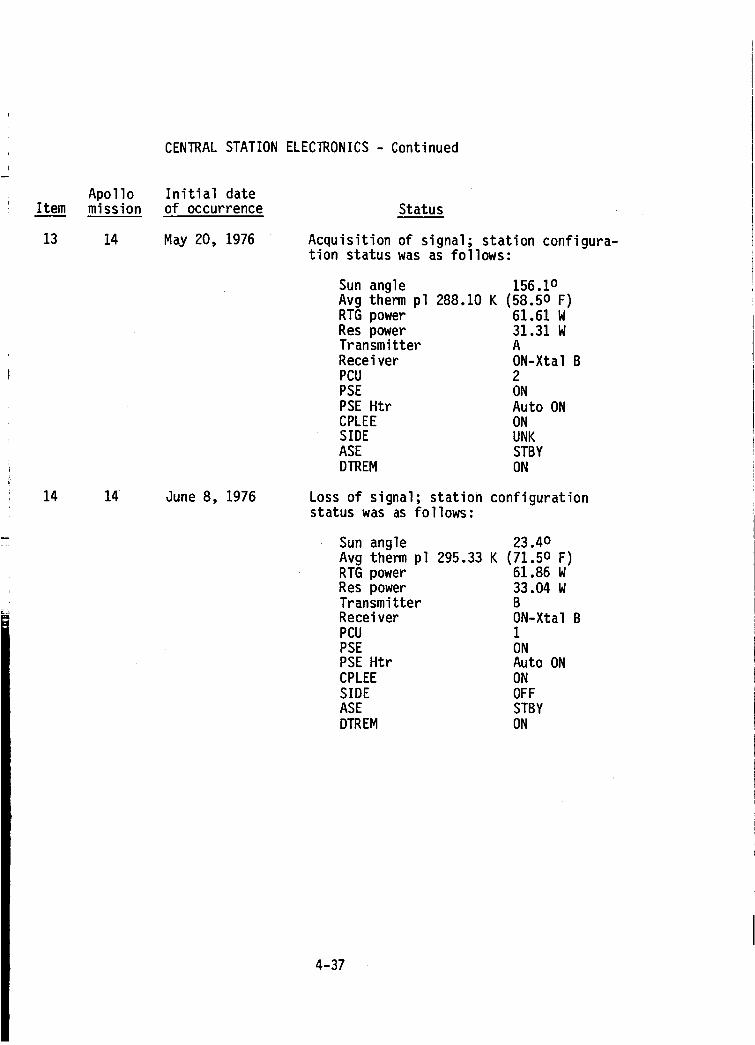
CENTRALSTATIONELECTRONICS- Continued
Item
13
14
Apollomission
14
14
Initial date
of occurrence Status
May 20, 1976
June 8, 1976
Acquisition of signal; station configura-tion status was as follows:
Sun angle 156.1oAvg therm pl 288.10 K (58.5o F)RTG power 61.61 WRes power 31.31 WTransmitter A
Receiver ON-Xtal BPCU 2
PSE ON
PSE Htr Auto ONCPLEE ONSIDE UNKASE STBY
DTREM ON
Loss of signal; station configurationstatus was as follows:
Sun angle 23.4oAvg therm pl 295.33 K (71.5o F)RTG power 61.86 W
Res power 33.04 WTransmitter BReceiver ON-Xtal BPCU 1
PSE ONPSE Htr Auto ON
CPLEE ON
SIDE OFFASE STBY
DTREM ON
4-37
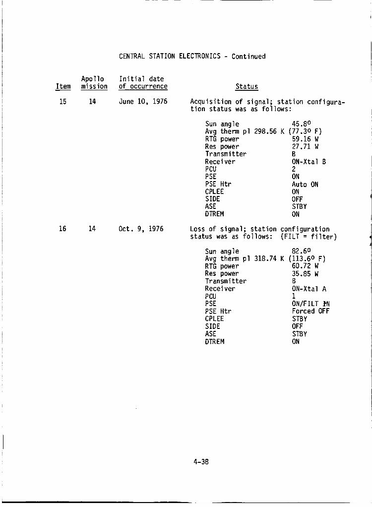
CENTRALSTATIONELECTRONICS- Continued
Item
15
16
Apollomission
14
14
Initial dateof occurrence Status
June 10, 1976
Oct. 9, 1976
Acquisition of signal; station configura-tion status was as follows:
Sun angle 45.8oAvg therm pl 298.56 K (77.3o F)RTG power 59.16 W
Res power 27.71WTransmitter B
Receiver ON-Xtal BPCU 2PSE ON
PSE Htr Auto ONCPLEE ONSIDE OFF
ASE STBYDTREM ON
Loss of signal; station configuration
status was as follows: (FILT = filter)
Sun angle 82.6°Avg therm pl 318.74 K (113.6o F)RTG power 60.72 W
Res power 35.85 WTransmitter BReceiver ON-Xtal A
PCU 1
PSE ON/FILTPSE Htr Forced OFFCPLEE STBY
SIDE OFFASE STBY
DTREM ON
4-38
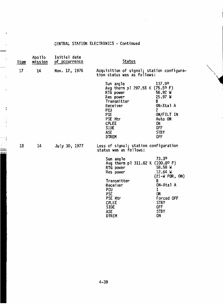
CENTRAL STATION ELECTRONICS - Continued
Item
17
18
Apollomission
14
14
Initial dateof occurrence Status
Nov. 12, 1976
July 30, 1977
Acquisition of signal; station configura-tion status was as follows:
Sun angle 137.9oAvg therm pl 297.55 K (75.5o F)RTG power 56.92 W
Res power 25.97 WTransmitter B
Receiver ON-Xtal A
PCU 2PSE ON/FILT INPSE Htr Auto ON
CPLEE ONSIDE OFF
ASE STBYDTREM OFF
Loss of signal; station configurationstatus was as follows:
Sun angle 73.3o
Avg therm pl 311.62 K (100.8o F)RTG power 58.58 WRes power 12.64 W
(21-W PDR, ON)Transmitter BReceiver ON-Xtal A
PCU 1PSE ONPSE Htr Forced OFF
CPLEE STBYSIDE OFF
ASE STBYDTREM ON
4-39
Item
19
20
Apollomission
14
12, 15,
16, and17
12 to 17
CENTRAL STATION ELECIRONICS - Continued
Initial dateof occurrence Status
Aug. 4, 1977
NIA
N/A
Acquisition of signal; station configura-tion status was as follows:
Sun angle 130.3o
Avg therm pl 289.77 K (61.5o F)RTG power 57.58 WRes power 13.04 WTransmitter B
Receiver ON-Xtal APCU 2
PSE STBY
PSE Htr N/ACPLEE STBYSIDE UNKASE STBY
DTREM ON
The station was reconfigured to PCU 1
and PSE to ON by ground commands and ap-peared to be operating normally.
Performance of the Apollo 12, 15, 16,
and 17 central stations was essentially
nominal. Although the original designrequirement for ALSEP was a 1-yr life,much longer useful lifetimes were real-ized.
A summary of ALSEP status on Sept. 29,1977, day before termination, is givenin table 4-I.
4-40
Item
Note
CENTRALSTATIONELECTRONICS- Concluded
Apollo Initial datemission of occurrence Status
15 & 17 Jan. 1, 1979 After the termination of ALSEP support atJSC on Sept. 30, 1977, monitoring of the
...................._;,_- ...........AL-5_P-transmit-terwas accomplished onan
intermittent basis by the tracking sta-
tions. During the period Mar. to Juneof 1978, the Apollo 17 ALSEP stopped
transmitting and also stopped respondingto ground commands.
The Apollo 15 RTG power output had de-
graded to a level that would not sustainboth heater power and transmitter opera-
tion at lunar night. Therefore, transmitteroperation was occurring during the warmerlunar daytime when more power was avail-
able. In approximately Aug. 1978, thetransmitter signal stopped and attemptsto command were unsuccessful. This in-
dicates the RTG power degraded to belowthe threshold for transmitter operation.
4-41
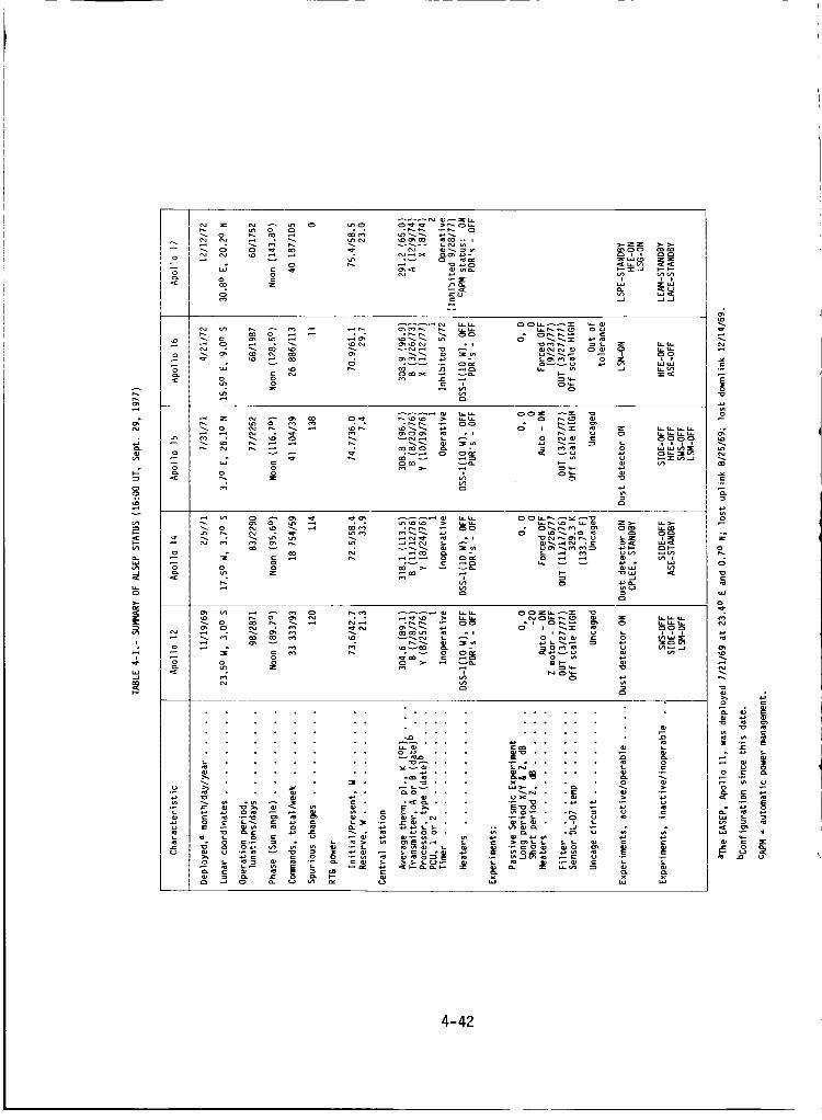
u_
t
-_. oe.l
o .-i
< %
Ln
o
< o
_e
_ _ _ _ .......... ._._._ _ _'_- .,
m_c3 i i _c_
_w-J ...I ..._
_ _ _ u. u-
• • • r_- r,_ ._ O0
=o 2N
la._.
i iww
iiii
o
o
I<
• r,,. r,,. ._ C30
up _ ,-_ a0e_
° °.._ _ _'_ z_- _._-
_d _N
•_ :_ _ _ _
C_C3_
o',_® =_ _ _' '='
N
_ cu
._s_ _ ...... _
cu
_._Nm .... _ "_'_
E'_O
._.o.Z " "_" "_ "_ =
..... _,_
°.
c_
csJ
o
0
o -_
-[_ ,,
4-42
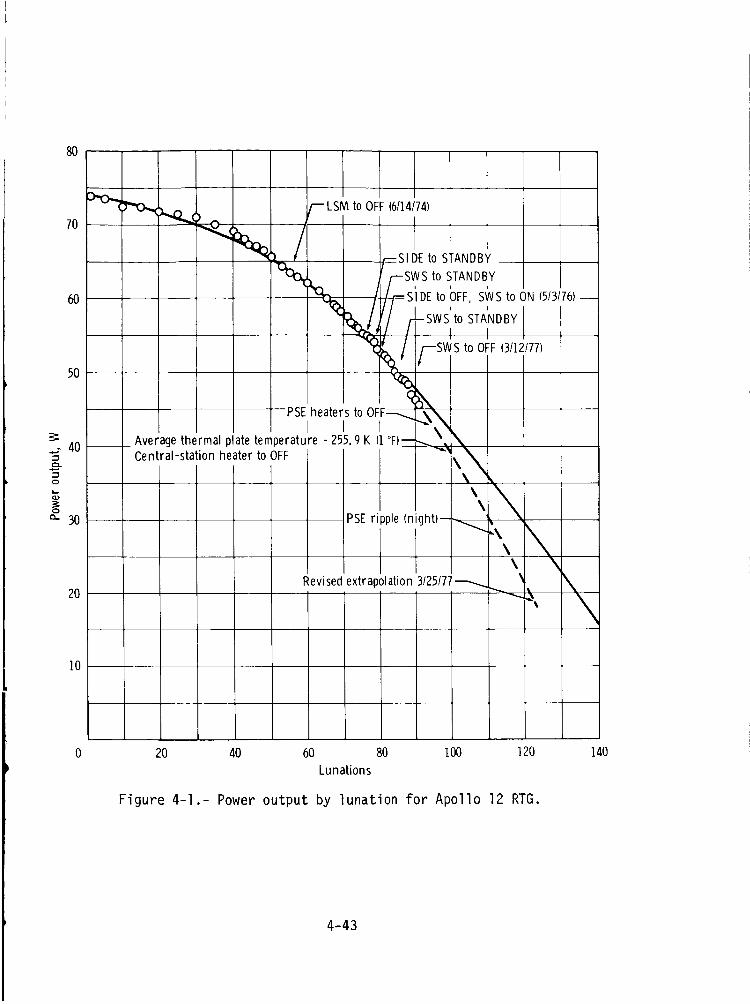
8O
- "r3_"_ , I _LSM toOFF (6114174)
,0 i
60 N (5/3/76)-
I % / I/_SWS to OFF(3/12/77)
PSE....heatersto OFF---...._,\_i "_'_I I I I ,,',
Average thermal plate temperature =255.9 K (1°F)_', \40_ Central-station heater to OFF _ _._.
",\\ ,
0
a_ 30 PSEripple (night)----.._,\
"\\
\
2ORevisedextrapolation 3/25/77_
\\\
10
0 20 40 60 80 100 120 140Lunations
Figure 4-I.- Power output by lunation for Apollo 12 RTG.
4-43
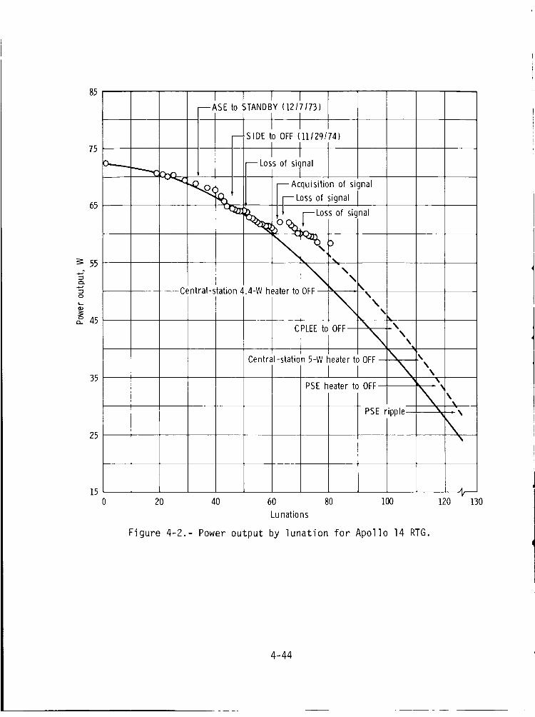
85
75
65
55
%0
_ 45
35
25
15
1 r Tto STANDBY(1217173)
20 40 60 80 100
Lunations
Figure 4-2.- Power output by lunation for Apollo 14 RTG.
120 130
4-44
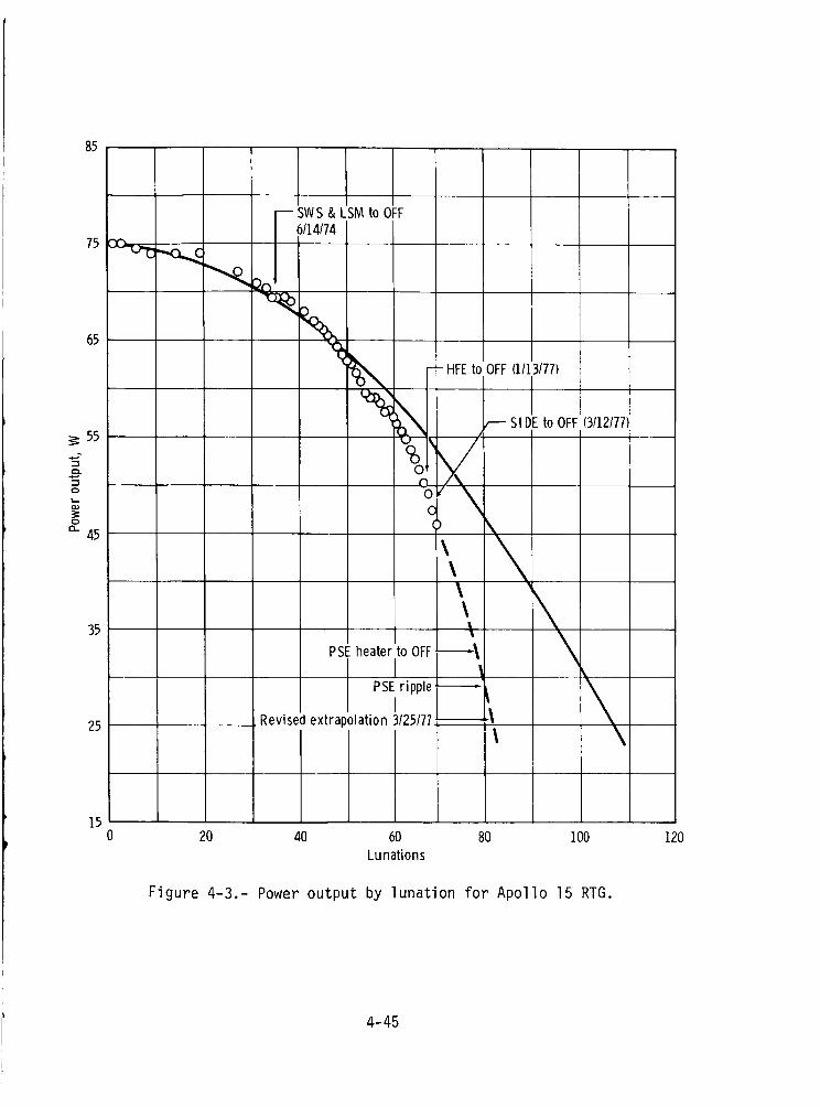
85
65
55
0
0
" 45
35
25
-- SWS & LSM to OFF6114174
PSE
,,_ - - HFEto
%'0-00(
\\\\
heater to OFF----_
PSE ripple .-_.-
Revised extrapolation 3/25/77
OFF (1113177)
-- Sl DE to OFF (3112177)
1520 40 60 80 100
Lunations
120
Figure 4-3.- Power output by lunation for Apollo 15 RTG.
4-45
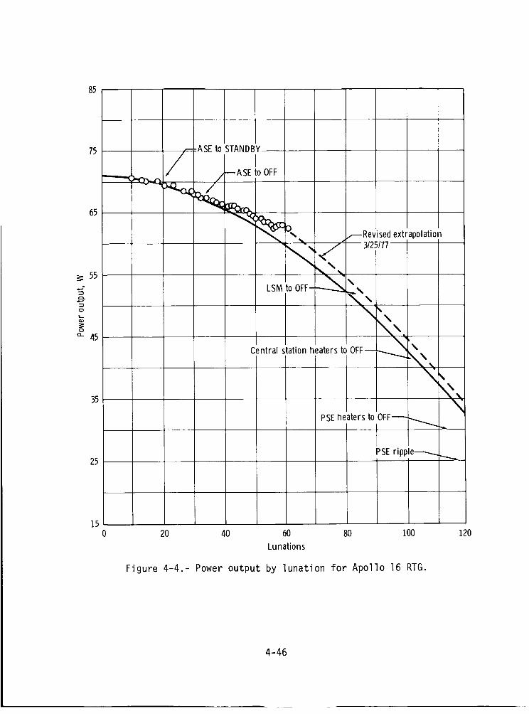
85
75
65
55
O
0
" 45
35
25
--ASEto
<STANDBY
--ASE to OFF
LSM
Central
_'_ _RevisedJ
,__. 3/25/77
to OFF-
station
extrapolation
%.heaterstoOFF---_._'_.
"<,,,
\
OFF_ _ ...
PSEheaters to
PSEripple_
1520 40 60 80 100
Lunations
Figure 4-4.- Power output by lunation for Apollo 16 RTG.
120
4-46
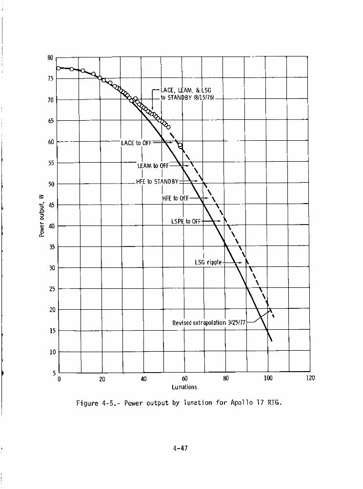
80
D---O-
75 °'KN
70
65
60
55
50
45
0
_ 400
35
30
25
20
15
10
_ _:LACE, LEAM,& LSG
____to STANDBY (8115176)--
xIL •
LACE to OFF--,_-- _
I i\°LEAMto OFF_---\\
HFEto STANDBY.-_. _'
\,i \HFEto OFF ..-- \
LSPE to OFF-\\
LSG ripple-_
Revisedextrapolation 3125177
\\\
%
20 40 60 80 100Lunations
Figure 4-5.- Power output by lunation for Apollo 17 RTG.
120
4-47
5. TERMINATION ANALYSIS (ENGINEERING CLOSEOUT TESTS)
Support operations for the Apollo Lunar Surface Experiments Packages(ALSEP's) were terminated September 30, 1977, thus concluding the longestcontinuous program of scientific data collection from a natural body in space.Throughout the ALSEP program, operational guidelines and mission rules pre-cluded the performing of engineering tests; the ALSEP operation was orientedtoward optimizing all systems for scientific data return.
During the long period of ALSEP operation (July 20, 1969, to Septem-ber 30, 1977), many engineering questions were raised but remained unansweredbecause of the operation constraint. Therefore, a period of engineeringcloseout testing was implemented before operations were terminated.
The series of engineering tests was devised approximately 3 monthsbefore support termination, and the tests were started July 25, 1977; theymay be classified into six groups:
1. Overload and "ripple off" tests
2. Passive seismic experiment (PSE) heater power tests
3. Central station cold-temperature tests
4. Central station redundant components tests
5. ALSEP timer functions for Apollo 15 and 16 missions
6. Cold soaking of the lunar surface magnetometer (LSM) and lunar sur-face gravimeter (LSG) experiments
STATUS OF EXPERIMENTS
The following matrix indicates the status of ALSEP experiments beforethe tests were implemented. (The symbol "0" indicates the experiment wasoperating, the symbol "NO" indicates "not operating", and no entry (--)indicates the experiment was not part of ALSEP during that mission.)
5-I

ALSEP unit
Central station 0
Passive Seismic 0Experiment (PSE)
Solar Wind NOSpectrometer (SWS)
Suprathermal lon NODetector Experiment(SIDE)
Lunar Surface Mag- NOnetometer (LSM)
Charged Particle --Lunar EnvironmentExperiment (CPLEE)
Heat Flow --Experiment (HFE)
Active Seismic --Experiment (ASE)
Lunar Surface --Gravimeter (LSG)
Lunar Mass --Spectrometer (LMS)
Lunar Ejecta and --Meteorites (LEAM)
Lunar Seismic --Profiling Experi-ment (LSPE)
Dust Detector 0(DTREM)
Apollo 12 Apollo 14 Apollo 15 Apollo 16 Apollo 17
0 0 0 0
0 0 0 --
NO
NO NO
0
NO 0
NO NO 0
NO -- NO
0 0
NO
NO
0
TEST CONSTRAINTS
The NASA Jet Propulsion Laboratory (JPL) needed the ALSEP transmittersfor its very long base interferometer (VLBI) experiments and requested thatthe transmitters be left "on" after the termination of ALSEP operation in1977. To comply with this request, and because of the remote possibility ofdust contamination of the laser ranging retro reflector of the Apollo 14 site,
5-2
a decision was made that no destructive engineering tests or grenade firingswould be attempted.
The Apollo 14 ALSEP operation was not continuous and its future opera-
tion was unpredictable. Therefore, a decision was made to cancel certain
tests on the Apollo 12 ALSEP, thus precluding the possibility of its losswhich would degrade the seismic network. {The downlink anomaly of the Apollo
14 ALSEP recurred on July 30, 1977, and downlink was recovered on August 4_1977; this represented the sixth loss of signal for the Apollo 14 station.)
ENGINEERING TESTS
The engineering tests and their objectives are listed in this subsection
by the Apollo mission number during which that ALSEP was deployed and byengineering test number. (The first two digits represent the Apollo mission
number; the last digit represents the test sequence.)
As the tests were performed, it became evident that some of the testscould be canceled because
1. The necessary data or information was obtained by previous testingin the closeout test sequence
2. The test itself would or might have a serious impact on remainingoperations
Apollo 12 ALSEP Tests
Test no. Type of test Objective
12-1
12-2
12-3
12-4
Overload the radioisotopethermoelectric generator
(RTG) by turning on addi-tional loads. Check the
power gains at sunset andpower losses at sunrise.
Determine if RTG power
output could be rejuvenated
as was the case for RTG powerof Apollo 14.
Check "ripple off" circuit by
turning SIDE and SWS to"standby."
Check PSE heater power.
Determine reserve power level
(for PSE) at which "rippleoff" occurs.
Determine power loads invarious PSE heater modes.
Check PSE operation withoutZ-motor heating.
Determine leveling frequencyand characteristics ofdrive motors.
5-3
Test no.
12-5
12-6
12-7
12-8
12-9
Type of test
Turn central station heat-
ers off and turn the powerdissipation resistors on
to reach a_proximately244 K (-20 F).
Turn central station heater(s)
on to reach approximately325 K (125° F).
Step the timer circuit seventimes.
Check redundant componentsof central station.
Command capabilities while
in high-bit-rate mode.
Objective
Pinpoint where PSE/central
station-electronics anomalystarts and determine other
central Station character-
istics at low temperature.
Determine central station
high-temperature operational
characteristics and parameters.
Determine status of timer elec-
tronics after 7 yr of operation.
Determine operational status
of alternate transmitter, pro-cessor, and power conditioningunit.
Determine if the command systemfunctions while in "HIGH BITRATE" without ASE.
Test no.
14-1
14-2
14-3
14-4
14-5
Apollo 14 ALSEP Tests
Type of test Objective
Heat central station power
regulator by maximum reservepower or by central stationheater.
Try to duplicate the cause of
signal loss from Apollo 14central station.
Check central station at ap-
proximately 325 K (125o F).
Check high-temperature opera-
tional characteristics and
parameters.
Fire one or all ASE mortars;
check high bit rate and geo-phones first and then checkASE "ARM CMD" in normal bit
rate.
Eliminate live ordnance and
check operation and thermal-
protective seal after longlunar exposure.
Check PSE heater power. Determine power loads in var-ious PSE heater modes.
Turn central station heaters
off and turn the power dis-sipation resistors on to
reach approximately 244 K(-20o F).
Check central station low-
temperature operationalcharacteristics and param-eters.
5-4
Test no.
14-6
14-7
14-8
Type of test
Check "ripple off" circuitby applying loads.
Check redundant componentsof central station.
Check timer steps.
Objective
Determine reserve power atwhich CPLEE and PSE ripple
to "standby."
Determine operational statusof alternate transmitter,data processor, and power
conditioning unit.
Determine that timer electronics
was still operational evenwith clock stopped.
Test no.
15-1
15-2
15-3
15-4
15-5
15-6
15-7
15-8
Apollo 15 ALSEP Tests
Type of test Objective
Check PSE heater power. Determine power loads in var-ious PSE heater modes.
Check PSE operation withoutheater.
Determine leveling frequencyand drive motor character-
istics.
Turn the HFE on. Determine if the data arestatic.
Turn central station heater(s)
on to reach approximately328 K (1300 F).
Determine high-temperatureoperational characteristicsand parameters of centralstation.
Check redundant componentsof central station.
Determine operational statusof alternate transmitter, dataprocessor, and power condition-ing unit.
Allow timer to "time out." Preclude resetting timerevery sunrise.
Command capabilities whilein high-bit-rate mode.
Determine if command systemfunctions while in "HIGH
BIT RATE" without ASE.
Overload the RTG. Determine if RTG power outputcould be rejuvenated as was
the case for Apollo 14.
5-5
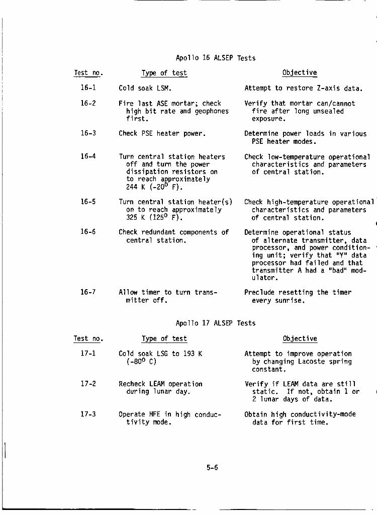
Test no.
16-1
16-2
16-3
16-4
16-5
16-6
16-7
Apollo 16 ALSEP Tests
Type of test
Cold soak LSM.
Objective
Attempt to restore Z-axis data.
Fire last ASE mortar; check
high bit rate and geophonesfirst.
Verify that mortar can/cannot
fire after long unsealedexposure.
Check PSE heater power. Determine power loads in variousPSE heater modes.
Turn central station heaters
off and turn the powerdissipation resistors on
to reach a_proximately244 K (-20u F).
Check low-temperature operationalcharacteristics and parametersof central station.
Turn central station heater(s)
on to reach approximately325 K _1250 F).
Check high-temperature operational
characteristics and parametersof central station.
Check redundant components ofcentral station.
Determine operational status
of alternate transmitter, dataprocessor, and power condition-
ing unit; verify that "Y" dataprocessor had failed and thattransmitter A had a "bad" mod-ulator.
Allow timer to turn trans-mitter off.
Preclude resetting the timer
every sunrise.
Test no.
17-1
17-2
17-3
Apollo 17 ALSEP Tests
Type of test
Cold soak LSG to 193 K
(-80o c)
Objective
Attempt to improve operation
by changing Lacoste springconstant.
Recheck LEAM operationduring lunar day.
Verify if LEAM data are stillstatic. If not, obtain 1 or
2 lunar days of data.
Operate HFE in high conduc-tivity mode.
Obtain high conductivity-modedata for first time.
5-6

Test no.
17-4
17-5
17-6
17-7
Type of test
Check "ripple off" circuit
by applying loads to cen-tral station.
Turn power dissipation re-sistor no. 1 on to reduce
central station to aproxi-
mately 244 K (-200 F)(external loads).
Turn automatic power manage-ment off to increase central
station to approximately
325 K (1250 F).
Check redundant components ofcentral station.
Objective
Determine sequence and reserve
power at which experiments
"ripple off."
Check low-temperature operationalcharacteristics and parametersof central station.
Check high-temperature opera-tional characteristics and
parameters of central station.
Determine operational statusof alternate transmitter, data
processor, and power condition-ing unit; determine power rout-ing of command decoder.
OVERLOAD AND "RIPPLE OFF" TESTS
Summary
Test 12-1.- Completed July 25, 1977; applied approximately 2 W overload;
RTG input voltage dropped from 15.69 Vdc to 15.27 Vdc; bus voltages of centralstation dropped proportionally; data multiplexer became erratic. Overloadwas removed and the central station was returned to normal operation. This
slight overload did not rejuvenate the RTG.
Test 12-2.- Completed July 25, 1977, as part of test 12-1. The PSE was
"rippled off" (i.e., automatically placed in standby) at some value less than1.79 W of reserve power.
Test 14-6.- Canceled because the test might cause the loss of the Apollo
14 ALSEP downlink and degrade the seismic network.
Test 15-8.- The test was canceled after a reevaluation of the possible
consequences; i.e., possibility of permanent loss of downlink from Apollo 15central station. Test 12-1 did not disclose any unexpected operation.
Test 17-4.- Test was canceled because the requirements were satisfied bythe results of test 12-2.
5-7
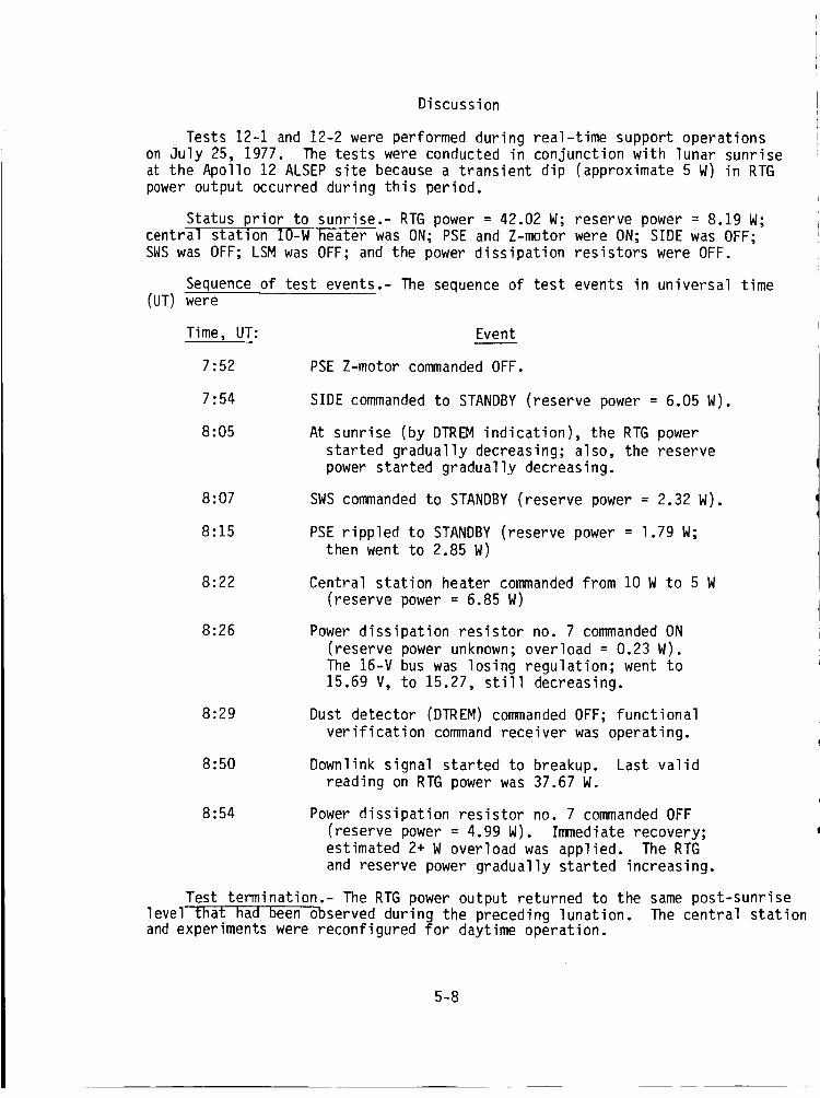
Discussion
Tests 12-I and 12-2 were performed during real-time support operationson July 25, 1977. Thetests were conducted in conjunction with lunar sunriseat the Apollo 12 ALSEPsite becausea transient dip (approximate 5 W) in RTGpoweroutput occurred during this period.
Status prior to sunrise.- RTG power = 42.02 W; reserve power = 8.19 W;
central station IO-W heater was ON; PSE and Z-motor were ON; SIDE was OFF;SWS was OFF; LSM was OFF; and the power dissipation resistors were OFF.
Sequence of test events.- The sequence of test events in universal time(UT) were
Time, UT: Event
7:52 PSE Z-motor commanded OFF.
7:54
8:05
SIDE commanded to STANDBY (reserve power = 6.05 W).
At sunrise (by DTREM indication), the RTG power
started gradually decreasing; also, the reservepower started gradually decreasing.
8:07 SWS commanded to STANDBY (reserve power = 2.32 W).
8:15 PSE rippled to STANDBY (reserve power = 1.79 W;then went to 2.85 W)
8:22 Central station heater commanded from 10 W to 5 W
(reserve power = 6.85 W)
8:26
8:29
Power dissipation resistor no. 7 commanded ON(reserve power unknown; overload = 0.23 W).
The 16-V bus was losing regulation; went to
15.69 V, to 15.27, still decreasing.
Dust detector (DTREM) commanded OFF; functional
verification command receiver was operating.
8:50 Downlink signal started to breakup. Last validreading on RTG power was 37.67 W.
8:54 Power dissipation resistor no. 7 commanded OFF(reserve power = 4.99 W). Immediate recovery;estimated 2+ W overload was applied. The RTGand reserve power gradually started increasing.
Test termination.- The RTG power output returned to the same post-sunrise
level that had been observed during the preceding lunation. The central stationand experiments were reconfigured for daytime operation.
5-8
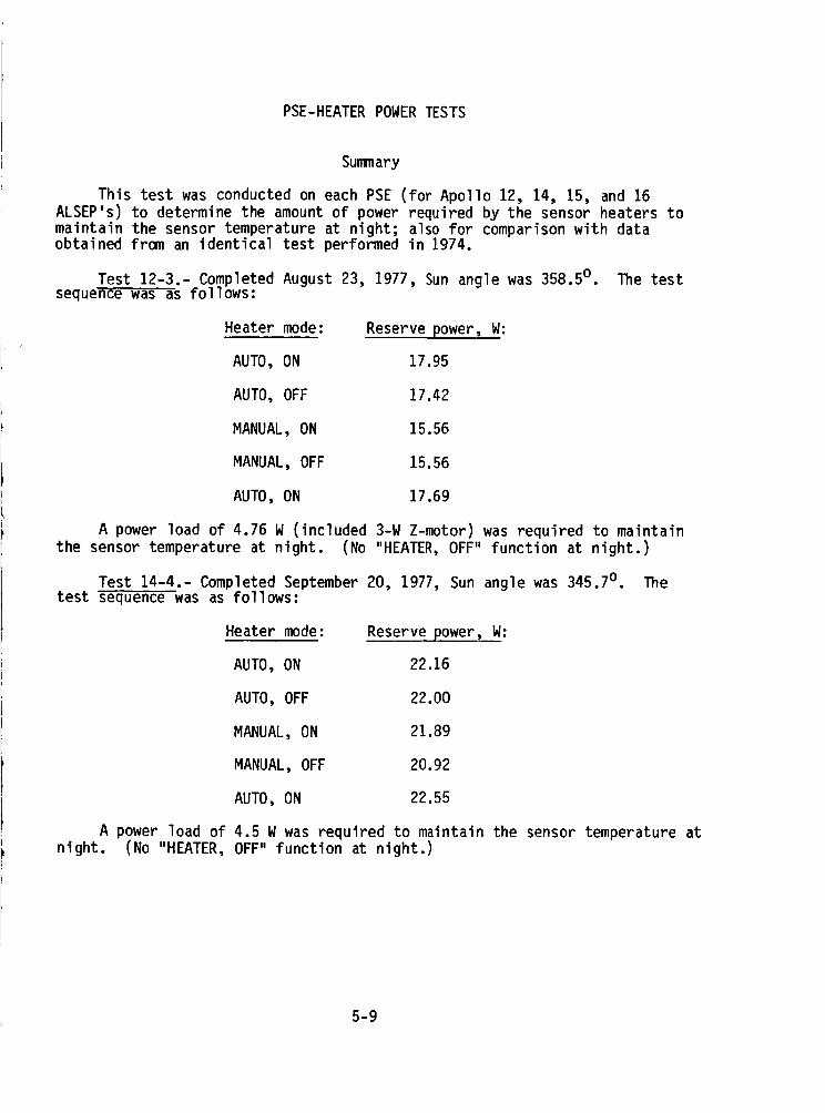
PSE-HEATERPOWERTESTS
Summary
This test was conductedon each PSE(for Apollo 12, 14, 15, and 16ALSEP's)to determine the amountof powerrequired by the sensor heaters tomaintain the sensor temperature at night; also for comparisonwith dataobtained from an identical test performed in 1974.
Test 12-3.- CompletedAugust 23, 1977, Sunangle was358.5° . The testseque_-_w_ _s follows:
Heater mode: Reserve power, W:
AUTO, ON 17.95
AUTO, OFF 17.42
MANUAL, ON 15.56
MANUAL, OFF 15.56
AUTO, ON 17.69
A power load of 4.76 W (included 3-W Z-motor) was required to maintain
the sensor temperature at night. (No "HEATER, OFF" function at night.)
Test 14-4.- Completed September 20, 1977, Sun angle was 345.7 o. Thetest sequence was as follows:
Heater mode: Reserve power, W:
AUTO, ON 22.16
AUTO, OFF 22.00
MANUAL, ON 21.89
MANUAL, OFF 20.92
AUTO, ON 22.55
A power load of 4.5 W was required to maintain the sensor temperature atnight. (No "HEATER, OFF" function at night.)
5-9
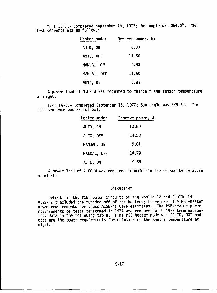
Test 15-1.- Completed September 19, 1977; Sun angle was 354.0o.test sequence was as follows:
Heater mode: Reserve power, W:
AUTO, ON 6.83
AUTO, OFF 11.50
MANUAL, ON 6.83
MANUAL, OFF 11.50
AUTO, ON 6.83
_]le
A power load of 4.67 W was required to maintain the sensor temperature
at night.
Test 16-3.- Completed September 16, 1977; Sun angle was 329.30 . The
test sequence was as follows:
Heater mode: Reserve power, W:
AUTO, ON 10.60
AUTO, OFF 14.53
MANUAL, ON 9.81
MANUAL, OFF 14.79
AUTO, ON 9.55
A power load of 4.00 W was required to maintain the sensor temperature
at night.
Discussion
Defects in the PSE heater circuits of the Apollo 12 and Apollo 14
ALSEP's precluded the turning off of the heaters; therefore, the PSE-heaterpower requirements for these ALSEP's were estimated. The PSE-heater power
requirements of tests performed in 1974 are compared with 1977 termination-test data in the following table. (The PSE heater mode was "AUTO, ON" and
data are the power requirements for maintaining the sensor temperature at
night.)
5-10
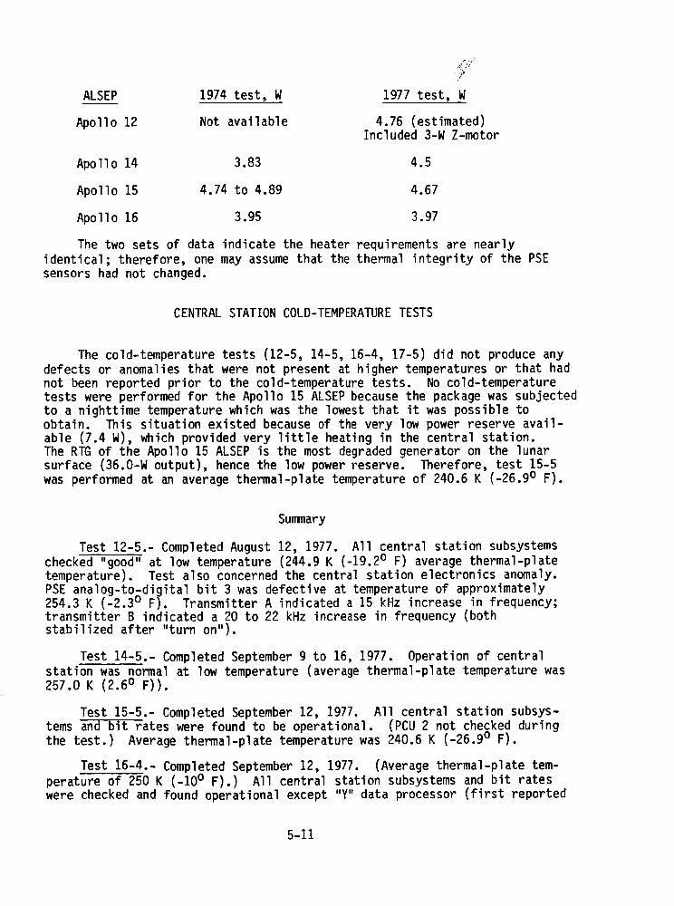
ALSEP 1974 test, W
Apollo 12 Not available
1977 test, W
4.76 (estimated)Included 3-W Z-motor
Apollo 14 3.83 4.5
Apollo 15 4.74 to 4.89 4.67
Apollo 16 3.95 3.97
The two sets of data indicate the heater requirements are nearly
identical; therefore, one may assume that the thermal integrity of the PSE
sensors had not changed.
CENTRAL STATION COLD-TEMPERATURE TESTS
The cold-temperature tests (12-5, 14-5, 16-4, 17-5) did not produce any
defects or anomalies that were not present at higher temperatures or that hadnot been reported prior to the cold-temperature tests. No cold-temperaturetests were performed for the Apollo 15 ALSEP because the package was subjected
to a nighttime temperature which was the lowest that it was possible toobtain. This situation existed because of the very low power reserve avail-
able (7.4 W), which provided very little heating in the central station.The RTG of the Apollo 15 ALSEP is the most degraded generator on the lunarsurface (36.0-W output), hence the low power reserve. Therefore, test 15-5
was performed at an average thermal-plate temperature of 240.6 K (-26.90 F).
Summary
Test 12-5.- Completed August 12, 1977. All central station subsystems
checked "good" at low temperature (244.9 K (-19.20 F) average thermal-platetemperature). Test also concerned the central station electronics anomaly.
PSE analog-to-digital bit 3 was defective at temperature of approximately254.3 K (-2.3° F). Transmitter A indicated a 15 kHz increase in frequency;transmitter B indicated a 20 to 22 kHz increase in frequency (bothstabilized after "turn on").
Test 14-5.- Completed September 9 to 16, 1977. Operation of central
station was normal at low temperature (average thermal-plate temperature was
257.0 K (2.60 F)).
Test 15-5.- Completed September 12, 1977. All central station subsys-tems and bit rates were found to be operational. (PCU 2 not checked during
the test.) Average thermal-plate temperature was 240.6 K (-26.90 F).
Test 16-4.- Completed September 12, 1977. (Average thermal-plate tem-
perature of 250 K (-100 F).) All central station subsystems and bit rateswere checked and found operational except "Y" data processor (first reported
5-11
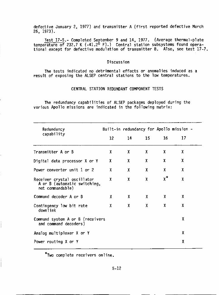
defective January 2, 1977) and transmitter A (first reported defective March26, 1973).
Test 17-5.- Completed September 9 and 14, 1977. (Average thermal-plate
temperature of 232.7 K (-41.20 F).) Central station subsystems found opera-
tional except for defective modulation of transmitter B. Also, see test 17-7.
Discussion
The tests indicated no detrimental effects or anomalies induced as a
result of exposing the ALSEP central stations to the low temperatures.
CENTRAL STATION REDUNDANT COMPONENT TESTS
The redundancy capabilities of ALSEP packages deployed during the
various Apollo missions are indicated in the following matrix:
Redundancy
capability
Built-in redundancy for Apollo mission -
12 14 15 16 17
Transmitter A or B X
Digital data processor X or Y X
Power converter unit I or 2 X
Receiver crystal oscillator XA or B (automatic switching,not commandable)
Command decoder A or B X
Contingency low bit rate Xdownlink
Command system A or B (receiversand command decoders)
Analog multiplexer X or Y
Power routing X or Y
X X X X
X X X X
X X X X
X X X* X
X X X X
X X X X
*Two complete receivers online.
5-12
Summary
Test 12-8.- Completed August 12, 1977 (with test 12-5) and September 20,
1977. All central station subsystems and bit rates were found operational;PCU 2 was not checked in test 12-8 or 12-5.
Test 14-7.- Completed September 19, 1977. All central station subsys-
tems checked "good" (PCU 2 not checked during this test), and all bit rateswere operational (PCU 2 not checked). Note that PCU 2 was checked duringthe ALSEP downlink recovery.
Test 15-5.- Completed September 12, 1977. All central station subsys-
tems and bit rates were found to be operational (PCU 2 not checked duringthis test).
Test 16-6.- Completed September 12, 1977. All central station subsys-
tems were found operational except for defective "Y" data processor andtransmitter A (see test 16-4).
Test 17-7.- Completed September 14, 1977. All redundant systems were
found operational except command system A, which rejected 14 of the 15commands, and transmitter B modulation, which made the data useless. Trans-
mitter B was first reported defective on December 9, 1974. All bit rateswere operational.
Discussion
Results of the tests indicated that all the redundant components wereoperational except the following:
ALSEP mission Component
Apollo 16 "Y" data processor (first reported defectiveJanuary 2, 1977)
Apollo 16 Transmitter A (first reported defective
March 26, 1973)
Apollo 17 Command system A (first reported defective
August 16, 1974)
Apollo 17 Transmitter B (first reported defective
December 9, 1974)
When support operations were terminated, there had been no additional
failures of any ALSEP redundant components.
5-13
TIMER"TIMEOUT"TESTS
Summary
Test 15-6.- Completed August 29, 1977. Timer did not perform the trans-mitter "turn off" function.
Test 16-7.- Completed August 29, 1977. Transmitter "turn off" by means
of the timer occurred at 20:42:17 UT, August 29, 1977. The transmitter was
commanded on by means of mode 1 commanding from the Ascension trackingstation.
Discussion
The ALSEP systems for the Apollo 15 and 16 missions provided a "reset-
table timer" that had an output signal to turn the transmitter off at the
end of 97 days; however, the timer would not reset itself to turn the trans-mitter "on." The transmitter could be turned on by ground command but thetimer control of "TRANSMITTER OFF" was nullified; thus, if command capabil-
ities were lost, the transmitter would continue to operate as long as suf-ficient power existed.
Normal operation of these ALSEP's was to reset the timers before station
sunrise, thus precluding transmitter "turn off" by means of the timer. Toimplement tests 15-6 and 16-7, the timers were not reset.
The Apollo 16 transmitter "turned off" at 20:42:17 UT on August 29,
1977, and was commanded "on" again by the tracking station. Because of a
failure in the timer logic, the "turn off" function did not occur for the
Apollo 15 ALSEP transmitter.
The transmitters can be turned "off" or "on" by means of normal uplink
commands. The Apollo 16 station was commanded on at the completion of thetest to comply with the JPL request for use of the stations in its VLBI
experiments.
No timer "timeout" tests were conducted for Apollo 12 and 14 missionsbecause the mechanical timers for both missions had been defective since
shortly after deployment on the lunar surface. The ALSEP timer for theApollo 17 mission did not provide a "TRANSMITTER OFF" function.
COLD SOAKING THE LSM AND LSG EXPERIMENTS
Summary
Test 16-1.- Completed March 14, 1977. Test was unsuccessful.
5-14
Test 17-I.- Completed March 16, 1977. Temperature would not decrease
to 193 K (-800 C). All LSG voltages decreased and the digital data becamescrambled. The LSG command decoder became inoperative. Lowest temperature
achieved was estimated at 198 K (-750 C). The test was terminated and wasunsuccessful.
Discussion
Test 16-1 was conducted as a means to recover science data from a
defective Z-axis sensor on the Apollo 16 LSM; test 17-1 was an attempt to
balance the mass in the LSG sensor of Apollo 17.
For a brief cooldown period, the Apollo 16 LSM was commanded "off" at
18:57 UT on March 14, 1977, and was commanded back "on" at 22:02 UT of the
same day. The cooldown and reinitiation of the LSM was an attempt to regainscience data from the Z-axis sensor that had been static since March 1975.
The attempt was unsuccessful; it was performed at the request of the
Principal Investigator.
The Apollo 17 LSG was commanded "off" for cooldown between the opera-tional support period of March 13 to 16, 1977, except for approximately 2
hours each day to obtain data. The instrument temperature was 198 K (-750C) (estimated) at each data take. The digital data from the digital multi-
plexer became scrambled, whereas the analog data remained valid at these lowtemperatures. Attempts to move the beam from the top position have been un-successful. On March 16, 1977, the decoder would not execute commands that
were transmitted by ground control.
CANCELED TESTS
The following tests were canceled for the reasons noted:
Test Reason
12-4 Potential damage to drive motorswith resultant degradation ofthe seismic network.
12-6 Possible damage to central station.With the unpredictable operation
of the Apollo 14 ALSEP, loss ofthe Apollo 12 ALSEP would degradethe seismic network.
12-7 Timer stepping would turn "on" theSIDE. The SIDE is defective and
possibly could overload the centralstation. Loss of the Apollo 12 ALSEP
would degrade the seismic network.
5-15
Test
12-9
14-1
14-2
14-3
14-8
15-2
15-3
15-4
15-7
16-2
16-5
17-2
Reason
Verified on the Apollo 16 andApollo 14 ALSEP's.
Loss of the Apollo 14 ALSEP would
degrade the seismic network.
High temperatures in the central
station could possibly causethe loss of this ALSEP and result
in degradation of the seismicnetwork.
Canceled because tests indicate that
the arming capacitors will not charge.
Timer stepping would turn "on" the SIDE,
which is defective and would possiblyoverload the central station and re-sult in loss of the transmitter.
Data from LOS/AOS anomaly of Apollo 14ALSEP indicate the drive motors will
not drive at low temperatures. Test
15-1 indicates normal heater powerat night.
Canceled because the HFE was defective;this could possibly overload the cen-tral station and result in loss of
the ALSEP.
Canceled because the test could result
in possible loss of the ALSEP.
Canceled because this information
was obtained during the Apollo 14and 16 ALSEP tests.
Canceled. An arming command was trans-mitted but arming capacitors wouldnot charge. Mortar box was improperlyoriented because of previous mortarfiring (May 1972).
Canceled because of possible loss ofthe ALSEP.
The LEAM was checked during each supportperiod; LEAM science data alwaysdefective.
5-16

Test
17-3
17-6
Reason
Canceled; Principal Investigator antici-pated no usable data from the test.
Canceledbecauseof possible loss ofthe ALSEP.
CENTRALSTATIONCONFIGURATIONATTERMINATIONOFALSEPOPERATIONALSUPPORT
Operational support of the ALSEPprogramwasdiscontinued on Septem-ber 30, 1977. At the conclusion, the central stationswwere configured asfollows:
(No entry (--) indicates the componentis not applicable to that ALSEP.)
Component
Transmitter B
Receiver crystal B
Data processor Y
Power conditioning 1unit
Heaters Off
Power dissipation Offresistors
Command decoder --
Receiver --
Automatic power --
management
Power routing --
Apollo 12 Apollo 14 Apollo 15 Apollo 16 Apollo 17
B B B B
A A Unknown Unknown
Y Y X X
1 1 1 2
Off Off Off Unknown
Off Off Off Off
B
B
On
W
5-17
6. SIGNIFICANTALSEPSCIENTIFICRESULTS
A newera in lunar science was initiated on July 21, 1969, whenthefirst data acquisition wasobtained from the Apollo 11 central station onthe Moon. More sophisticated equipmentand experiment packagesevolvedduring the remaining Apollo missions that culminated with Apollo 17. Alarge amountof Apollo Lunar Surface ExperimentsPackage(ALSEP)data andtheir interpretation have been published in numerousreports and publica-tions. This section of the ALSEPTermination Report does not attempt torecapitulate the findings; instead, each ALSEPinvestigator was asked tobriefly summarizethe significant scientific results obtained from theALSEPexperiments. The participating investigators were
1. Passive Seismic Experiment- Gary V. Latham, University of Texasat Galveston, and Nafi Toks6z, MassachusettsInstitute of Technology
2. Lunar Near-Surface Structure (Active Seismic) - Robert L. Kovach,Stanford University
3. Lunar Surface Magnetometers- PalmerDyal, NASAAmesResearchCenter, and C. P. Sonett, University of Arizona
4. Suprathermal Ion Detector Experiment- John W. Freeman,Jr., RiceUniversity
5. Lunar Heat Flow Experiment- MarcusG. Langseth, ColumbiaUniversity
6. ChargedParticle Lunar EnvironmentExperiment- David L. Reasoner,Rice University
7. Cold CathodeGageExperiment - Francis S. Johnson, University ofTexasat Dallas
8. Lunar MassSpectrometer - John H. Hoffman,University of TexasatDallas
9. Lunar Surface Gravimeter - JosephWeber,University ofMaryland
10. Solar WindSpectrometer - ConwayW. Snyder, NASAJetPropulsion Laboratory
11. Lunar Ejecta andMeteorites - Otto E. Berg, NASAGoddardSpaceFlight Center
6-1

PASSIVE SEISMIC EXPERIMENT
Five seismic stations were deployed on the Moon during Apollo mis-sions 11, 12, 14, 15, and 16. The Apollo 11 station, powered by solarcells and intended for operation only during the lunar day, failed afterexposure to the first nighttime period. The remaining four stations,powered by radioisotope thermoelectric generators, have operated contin-uously since their initial activation. These four stations constitutethe Apollo seismic network. The network was completed in April, 1972,with the installation of the fourth station in the Descartes region ofthe southern highlands during Apollo 16. Each station contains fourseismometers. Three of these seismometers form a triaxial set (one sen-sitive to vertical motion and two sensitive to horizontal motion), withsensitivity to ground motion sharply peaked at 0.45 Hz. The fourth seis-mometer is sensitive to vertical motion with peak sensitivity at 8 Hz.
Lunar Seismicity (By Gary V. Latham)
The seismic data indicate that there are three primary types ofsignals: (i) deep moonquakes, (2) shallow moonquakes, and (3) meteoroidimpacts.
1. The deep moonquakes are repetitive, occurring at fixed locationsand at monthly intervals (27 to 28 days) with remarkable regularity. Themoonquake foci occur in two narrow belts in the nearside of the Moon.Both belts are 100 to 300 km wide, approximately 200 km long, and 800 andI000 km deep. These events are clearly correlated with tidal deformationof the Moon.
2. The shallow moonquakes are located on or near the surface of theMoon, leaving a large gap in seismic activity between the zone of the shal-low moonquakes and the deep moonquakes. There are no marked regularitiesin their occurrence. These events constitute a small proportion of thetotal observed seismic events; they are significant because of the highenergy release. These events average approximately 5/yr, and are mostlikely less than 100 km deep.
3. The meteoroid impacts have a distinctive seismic characteristicin contrast to the two types of moonquake characteristics. The meteoroidimpacts generate the largest observed signals.
There has been only one farside meteoroid impact registered by theseismic network.
Results from the analysis of Apollo seismic network data suggest that
1. Primitive differentiation occurred in the outer shell of the Moonto a depth of approximately 300 km.
2. The central region of the Moon is presently molten to a radius ofbetween 200 and 300 km.
6-2
The best model for the zone of original differentiation appears to be a
crust 40 to 80 km thick, ranging in composition from anorthositic gabbroto gabbro; overlying an ultramafic cumulate (olivine-pyroxene) approxi-
mately 250 km thick. The best candidate for the molten core appears tobe iron or iron sulphide.
Structure of the Moon (By Nafi Toks_z)
The lunar seismic network established by the Apollo Program has pro-vided the best data for determining the internal structure of the Moon.
Seismic waves can penetrate through a terrestrial planet and provide de-tailed information about its interior. On the Moon, both artificial im-pacts and natural events (meteoroid impacts and moonquakes) were used as
seismic sources. By using travel times and amplitudes of seismic phasestogether with the most advanced techniques of seismogram analysis, inves-tigators have determined the existence of a lunar crust and properties ofthe lunar mantle and deep interior.
Crustal characteristics.- The determination of crustal structure,
using artificial impacts in the Oceanus Procellarum region around the
ALSEP stations of Apollo 12 and 14, was the first accomplishment. Thecrust is two layered, with a total thickness of approximately 60 km in
this region. There is a secondary boundary at a 20-km depth. More re-cently, it has proved possible to determine the crustal thickness at the
ALSEP 16 site by using crustal reverberation ("pegleg" multiples) thatfollowed the S-wave arrivals from deep focus moonquakes. Preliminary
results suggest that the total crustal thickness under ALSEP 16 is approx-imately 75 km and that the 20-km interface also exists under ALSEP 16. Onthe basis of ultrasonic measurements of seismic velocities on returned
lunar samples, it is suggested that the crust is composed predominantly ofanorthositic and gabbroic composition.
Using data from deep and shallow moonquakes and meteoroid impacts,
determination of lunar structure is extended to great depths. The lunar
upper mantle has a fairly homogeneous velocity structure down to depths ofbetween 300 and 500 km. The compressional wave velocity is approximately8 km/sec, and the shear wave velocity is approximately 4.6 km/sec. These
velocities are consistent with an olivine or olivine-pyroxene composition,although other compositions are possible. The seismic quality factor Q,
which describes the attenuation of seismic waves due to anelastic absorp-tion as they traverse a medium, is approximately 5000 for P waves in
this region. This very high value indicates that very little absorptionis taking place, almost certainly because of a complete absence of wateror other volatiles.
Below a depth of 300 to 500 km, there is a decrease in the seismic
velocities. Arrivals from deep-focus moonquakes indicate that the seismic
velocities in the depth range of 500 to 1000 km are 7.5 km/sec for com-
pressional waves and 4.1 km/sec for shear waves. The quality factor Qfor compressional waves in this depth range is approximately 1500. The
changes in seismic velocity in this depth range could be due to the sub-stitution of iron for magnesium in, for example, the olivine or pyroxenemineral series. Below a depth of approximately 1000 km, the attenuation
6-3

increases, probably due to increased temperatures toward the meltingpoint. Sufficient data does not exist at present to determine whethera small molten core exists inside the Moon.
Moonquakes and tides.- From the time of their discovery, a class of
events known as deep-focus moonquakes has presented a challenge to in-
vestigators. Unlike the overwhelming majority of earthquakes, moonquakesrepeat "time after time" at the same focus at monthly intervals. Thismonthly periodicity is controlled by the tidal forces of the Earth upon
the Moon, and, in fact, the rate of energy release also exhibits 206-dayand 6-year periodicities, also controlled by the tides. There have been
approximately 70 foci discovered so far, with focal depths between approx-imately 700 and 1100 km. All located epicenters except one lie on thenear side of the Moon, but this is probably because the Passive SeismicExperiment array is on the near side of the Moon and not because deep-focus
moonquakes are limited to the near side. Deep-focus moonquakes constitutethe vast majority of teleseismic events observed by the ALSEP network,although they are small events, having a maximum Richter magnitude of 1or 2.
Several questions arise regarding moonquakes. Why are they so deep?
What forces are responsible for them? Are they related to tides? To an-swer these questions, theoretical calculations of the stress distributiondue to tidal forces have been made using realistic models of the distri-
bution of elastic constants within the Moon. According to these calcula-tions, the concentration of focal depths between 700 and 1100 km is due
to a decrease in the shear modulus in this region, thus localizing thestress in this region. The epicenters, however, do not correspond to lo-cal maximums in the tidal stress, and must be due to local inhomogeneities,
possibly previously existing faults. The time history of the epicenters,which includes events of reversed polarity, follows the tidal cycles so
closely that it appears likely that the tidal forces are a major factorfor triggering deep-focus moonquakes.
LUNAR NEAR-SURFACE STRUCTURE (ACTIVE SEISMIC)
By Robert L. Kovach
Seismic refraction data obtained at the Apollo 14, 16, and 17 land-
ing sites permit a compressional wave velocity profile of the lunar nearsurface to be derived. Although the regolith is locally variable in thick-ness, it possesses surprisingly similar seismic characteristics. Beneath
the regolith at the Apollo 14 Fra Mauro site and the Apollo 16 Descartessite is material with a seismic velocity of :300 m/sec, believed to be
brecciated material or impact-derived debris. Considerable detail is known
about the velocity structure at the Apollo 17 Taurus-Littrow site. Seismicvelocities of 100, 327, 495, 960, and 4700 m/sec are observed. The depthto the top of the 4700-m/sec material is 1385 m, compatible with gravityestimates for the thickness of mare basaltic flows, which fill the Taurus-
Littrow valley. The observed magnitude of the velocity change with depthand the implied steep velocity-depth gradient of >2 km sec-1 km-I are much
larger than have been observed on compaction experiments on granular
6-4
materials and preclude simple cold compactionof a fine-grained rock powderto thicknesses of the order of kilometers. Thelarge velocity changefrom960 to 4700m/sec is more indicative of a compositional change than a changeof physical properties alone. This high velocity is believed to be repre-sentative of the material that forms the lunar highlands.
LUNARSURFACEMAGNETOMETERS
Three lunar surface magnetometerswere successfully deployed on theMoonas part of the ALSEPprogramduring the Apollo 12, 15, and 16 mis-sions. Data from these instruments, together with simultaneous measure-ments from other experiments on the Moonand in lunar orbit, have beenused to study properties of the lunar interior and the lunar environment.
Analysesof lunar magnetic data were usedto study the followingproperties of the Moon:
1. Electrical conductivity, temperature, and structure of the lunarcrust and deep interior
2. Lunar magnetic permeability and iron abundance,also the inferredlimits on the size of a highly conducting lunar core
3. Lunar surface remanentmagnetic fields: present-day properties,interaction with the solar wind, and origin by thermoelectric generation
4. Lunar environment: lunar atmosphereand ionosphere in thegeomagnetictail, also velocity and thickness of the magnetosphericboundaries
Lunar Electrical Conductivity andStructure
(By PalmerDyal)
Electrical conductivity of the deeplunar interior has been investi-gated by using data from a total of seven lunar magnetometersto analyzethe eddy-current response of the Moon. Extensive analysis of one excep-tionally large transient has allowed substantial improvementin resolutionand sounding depth for conductivity analysis. Also, a newtechnique hasbeen applied to conductivity analysis in which simultaneous data are usedfrom a network of one close-orbiting and two surface magnetometers. As aresult, it has been found that the lunar conductivity rises rapidly withdepth in the crust to approximately 10-3 mhos/mat a 200- to 300-kmdepth,which corresponds to the upper-mantle boundaryreported in seismic results.Froma 300- to 900-kmdepth, the conductivity rises moregradually to3 x 10-2 mhos/m.
An upper limit has been placed on the averageelectrical conductivityof the lunar crust as the result of an investigation of toroidal inductionin the Moon. In the analysis, a theory is developedfor the sphericallysymmetriccase of the induction field totally confined to the lunar
6-5
interior or near-surface regions by a highly conducting plasma. Both sys-tematic instrumental errors and randomerrors have been included in thecrustal conductivity analysis, in which it is concluded that for an aver-age global crust thickness of approximately 80 km, inferred from seismicresults, the crust-surface electrical-conductivity upper limit is approxi-mately 10-_ mhos/m. Thetoroidal induction results lower the surfaceconductivity limit determined from eddy-current response analysis by approx-imately four orders of magnitude.
Lunar permeability.- Magnetic permeability and iron abundance of theMoon have been calculated by analysis of magnetization fields induced in
the permeable material of the Moon. When the Moon is immersed in anexternal field it is magnetized; the induced magnetization is a function
of the distribution of permeable material in the interior. Deployment of
Apollo magnetometers on the lunar surface permitted simultaneous measurementsof the total response field at the lunar surface as well as measurements
of the external inducing field by an Explorer 35 magnetometer. The total
response field B measured at the lunar surface by an Apollo magnetometeris the sum of the external and induced fields:
_B = Be + u.Be
where Be is the external magnetizing field, E.Be is the magnetizationfield induced in the permeable lunar material, an_ _ is a function of
the magnetic permeability.
From a data plot of the radial component of B compared to the radi-al component of H, the global lunar permeability has been determined to
be _ = 1.012 ± 0.006. The corresponding global induced dipole moment isapproximately 2 x 10¹⁴ T/cm3 (2 x 10¹⁸ G/cm3) for typical inducing fieldsof 10-_ T (10-4 G) in the lunar environment. The measured permeability
indicates that the Moon responds as a paramagnetic or weakly ferromagneticsphere and that the Moon is not composed entirely of paramagnetic material,but that ferromagnetic material such as free iron exists in sufficient
amounts to dominate the bulk lunar susceptibility.
Iron abundance.- Under the assumption that the permeable material inthe Moon is predominantly free iron and iron-bearing minerals, the lunarfree iron abundance has been determined to be 2.5 ± 2.0 wt.%. Total ironabundance has been calculated to be 9.0 ± 4.7 wt.%. Other lunar models
with a small iron core and with a shallow iron-rich layer have also been
examined in light of the measured global permeability.
Core size limits.- The lunar magnetic permeability determined from
magnetometer measurements has also been used to place limits on a possible
highly conducting core in the Moon. For this analysis, the Moon is repre-sented by a three-layer magnetic model: an outer shell of temperature
T below the Curie point Tc, for which permeability _ is dominated byferromagnetic free iron; an intermediate shell of T > Tc where permeabilityis approximately _o, (permeability of free space); and a highly conducting
core (a > 10_ mhos/m) modeled by _ = O. This core effectively excludes
6-6

external magnetic fields over time periods of days and therefore acts asa strongly diamagnetic region (_ + 0).
A theoretical analysis was conducted to relate the induced magneticdipole moment to the core size. The induced dipole moment has been deter-
mined from simultaneous Apollo 12 and Explorer 35 measurements to be (2.1± 1.0) x 1014 T/cm3 ((2.1 ± 1.0) x 1018 G/cm3) and from simultaneous Apollo
15 and 16 measurements to be (1.4 ± 0.9) x 1014 T/cm3 ((1.4 ± 0.9) x 1018G/cm3). The theoretical results show that the core size is a function of
the depth of the Curie isotherm and lunar composition, and that a highlyconducting core of maximum radius 535 km is possible for the extreme case
of a magnesium-silicate dominated orthopyroxene Moon with a Curie isotherm
depth of 250 km. Conductivity results verify this upper limit for a coreof conductivity greater than 10 mhos/m. However, the minimum radius for
a highly conducting core is zero, i.e., there is no positive indication
at this time that any core of conductivity greater than 10 mhos/m needexist in the Moon.
Permanent magnetic properties of remanent fields.- The permanent mag-netic fields of the Moon have been investigated using surface magnetometer
measurements at four Apollo sites. A lunar remanent magnetic field wasfirst measured in situ by the Apollo 12 lunar surface magnetometer that
was deployed on the eastern edge of Oceanus Procellarum. The permanentfield magnitude was (38 ± 3) x 10-_ T (38 ± 3 gammas), and the source ofthis field was determined to be local in extent. Subsequent to this meas-
urement of an intrinsic lunar magnetic field, surface magnetometers have
measured fields at the ApRllo 14, 15 and 16 sites. Fields of (103 ± 5)x 10-9 and (43 ± 6) x 10-_ T (103 ± 5 and 43 ± 6 gammas), at two sites
located approximately a kilometer apart, were measured by the Apollo 14lunar portable magnetometer at Fra Mauro. A steady field of (3.4 ± 2.9)x 10-9 T (3.4 ± 2.9 gammas) was measured near Hadley Rifle by the Apollo15 lunar surface magnetometer. At the Apollo 16 landing site, both a port-
able and stationary magnetometer were deployed; magnetic fields ranging be-tween 112 x 10-_ and 327 x 10-_ T (112 and 327 gammas) were measured atfive different locations over a total distance of 7.1 km at the Descartes
landing site. These are the largest lunar fields yet measured.
Thermoelectric origin of crustal remanent maqnetism.- Measurements of
remanent magnetization in returned lunar samples indicate that magneticfields of 10-7 to 10-4 T (103 to 105 gammas) existed at the surface of the
Moon at the time of crustal solidification and cooling. A thermoelectric
mechanism has been investigated to explain the origin of these magneticfields. When the crust was still only a few kilometers thick, infallingmaterial could have penetrated it, exposing the magma beneath and forming
many lava-filled basins. The resulting model has two lava basins, withdifferent surface temperatures, connected beneath the surface by magma.This configuration has the basic elements of a thermoelectric circuit:
two dissimilar conductors joined at two junctions that are at different
temperatures. The thermal electromotive force in the circuit depends onthe electronic properties of the lunar crust and the plasma; in particu-lar, on the difference in their Seebeck coefficients. For a relative See-
beck coefficient of ..... g . g103 uV/K. thermoelectrically enerated ma netic fields
ranging from approximately 10-b to 10-b T (I0j to 104 gammas) are calcu-
lated depending on basin sizes and separations. These fields are large
6-7
enoughto have produced the remanencein most of the returned lunar samples.Fields as high as approximately 10-4 T (105 gammas)(indicated for somereturned lunar samples) are attainable from the model if one uses upper-limit values of the Seebeckcoefficient and includes effects of solar-windcompressionof lunar surface fields. The thermoelectric mechanismis com-patible with the high degreeof inhomogeneityfound in measuredremanentfields andwith the absenceof a measurablenet global magnetic moment.
Apollo 12 and 15 Magnetometers
(By C. P. Sonett)
Twoprincipal results of the Apollo 12 and 15 Lunar Surface Magnetom-eter Experiments, are (1) the discovery of a permanentmagnetic field atthe Apollo 12 site with a regional (1 to 100 km) scale and (2) the discov-ery that the Moonrespondsstrongly to electromagnetic excitation by thesolar wind. The permanentmagnetic field was unexpectedbut is fully con-sistent with the discovery of paleomagnetismin Apollo 11 lunar samples.TheApollo 12 results have beenextended by Explorer 35 mappingof thelimb shocks. Very detailed mapsof the regional magnetization have beenmadeby the Apollo subsatellites.
The electromagnetic excitation is a newclass of planetary excita-tion by the solar wind. It is of intrinsic interest from the standpointof supersonic plasmaflow past planets. Fromthe standpoint of planetaryinteriors, a detailed procedure for electromagnetic sounding of the bulkelectrical conductivity of the Moon's interior has beendeveloped by usingthe excitation. Present-day research showsthe absenceof a metallizedcore of radius greater than 400 to 500 kmbut cannot yet rule out a coreof smaller radius. Conductivity at depths of 100 to 500 kmhave yieldeda model-dependentthermal gradient and heat flux consistent with the latestheat flow measurements. The persistence of a spikelike conductivity anom-aly at a depth of 150 to 250 km indicates that further work is required onincreasing data resolution to confirm this characteristic.
The Apollo 15 data suggest that the Imbrium Basin is slowly settling.This result comesfrom model calculations based uponthe Apollo 15 conduc-tivity data that showa ringlike resistivity, increasing at the edges ofthe mare. Settling of ImbriumBasin had beenpreviously suggested fromstudies of masconanisostasy, lunar transient events, and seismic activity.TheApollo 15 conductivity is reported to be repeated at MareSerenitatisby the Russian Lunikod data, thus increasing the likelihood that the Apollo15 conclusion is correct.
Themost recent research on Apollo 12 showsthat the Moonis excitedelectromagnetically by pressure fluctuations in the darkside diamagneticcavity. Theseare driven by the solar wind. The cavity acts like a sole-noid and the fringing field extends into the Moon. Thus, excitation is su-perimposeduponthe normal frontside induction forced by the integral mag-netic field.
6-8
SUPRATHERMALIONDETECTOREXPERIMENT
By John W. Freeman,Jr.
The results of the ALSEPSuprathermal Ion Detector Experiment (SIDE)maybe divided into two categories: those pertaining principally to theMoonand its interaction with its environment and those pertaining to theEarth's magnetotail.
Regarding the first category, the SIDEdemonstratedthe accelerationand reimplantation of atmospheric ions by the solar wind. By fitting theobserved ion energy spectra to neon and argonmasses,surface numberden-sities for these gases were obtained near the terminator. Also, the elec-trostatic screening length of the surface electric field wasobtained andfound to be 2 orders of magnitudegreater than expected from Debyescreen-ing length theory. This is believed to be due to the presence of a cloudof hot solar-wind electrons near the terminator presumablygenerated bythe limb shock of the solar wind. The SIDEdata provide the only evidenceto date for such a cloud.
Efforts to find variations in the lunar atmosphereresulting from en-dogenouslunar gas emissions have beenfrustrating. The dayside lunar ion-osphere numberdensity was routinely monitored for manymonthsby acceler-ation of ambient ions into the detector by the artificial electric fieldprovided with the instrument. The ionospherewas found to vary with changesin the solar-wind flux and the extreme-ultraviolet (EUV)flux from the Sun.The solar-wind related enhancementssuggest extensive sputtering of thelunar soil. Theseenhancementstogether with EUVmodulations tend to maskatmospheric changesdue to lunar sources. Only one possible natural eventhas beenfound to date. This event, principally water vapor, must remainsuspect becauseof its proximity to the Apollo 14 mission. However, thelarge magnitude and the long time duration of the event argue against amission related source.
Using SIDEdata from other events, investigations have determineddirectly the dissipation time of rocket exhaust gases from the Apollolanding sites. Thee-folding decay time for heavier gases is found tobe approximately 1 month.
The SIDEmadethe first measurementsof the electric potential ofthe lunar surface in the solar wind on the dayside and terminator sideof the Moon. TheMoonwas found to be charged to approximately +10 V onthe dayside going to -100 V at sunset and sunrise. The SIDEobservationof sporadic fluxes of nightside ions suggests a nightside potential ofapproximately -250 V. The source of these nightside ions is not yetfully understood.
Regarding the secondcategory, the SIDEmadean important contributionto magnetospheric research by discovering a newplasmaregime in the lobesof the magnetotail. This regime consists of low-energy plasma streamingalong magnetic-field lines awayfrom the Earth. Theplasma, in additionto protons, is found to consist of singly ionized oxygenand/or nitrogen.The source of these ions is believed to be the Earth's ionosphere. This
6-9
has forced a reevaluation of current thinking regarding the source of theplasmamantle and boundary layer.
The SIDEhas also provided the best data on the plasmasheet and mag-net,sheath at lunar distances. As a result, several newtypes of plasmasheet spectra have been found and asymmetriesin the magnetoshethhavebeendiscovered. The SIDEhas provided the first observation of directentry of magnet.sheathplasma into the plasma sheet. The SIDEhas alsobeenused to study the propagation of the bowshock protons upstream inthe solar wind.
In summary,the SIDEhas beena very successful experiment providinginformation on several different areas of space science. Data analysis iscontinuing and newaspects of the data are still being uncovered.
LUNARHEATFLOWEXPERIMENT
By MarcusG. Langseth
The Heat Flow Experimentwasdesigned to makedirect observations ofthe rate of heat loss through the surface of the Moonat the Apollo land-ing sites. Twoof these experiments were deployed successfully during theApollo program; one at HadleyRille (Apollo 15) and the other at TaurusLittrow (Apollo 17). A third instrument wasdeployed at the Apollo 16 land-ing site, but a broken cable betweenthe central station and the experimentmadeit useless. The principal componentsof the experiment were probes,eachwith 12 thermometersof exceptional accuracy and stability, thatrecorded temperature variations at the surface and in the regolith downto2.5 m. TheApollo 15 experiment recorded temperatures for a period of 4.5years and the Apollo 17 probes, which were still returning accurate resultswhenthe instrument was turned off, recorded 4 years and 10 monthsof lunarsurface and subsurface temperatures. Thesedata provided a unique and valu-able history of the interaction of solar energy with lunar surface and theeffects of heat flowing from the deep interior out through the surface ofthe Moon. The interpretation of these data resulted in a clearer definitionof the thermal and mechanical properties of the upper 2 m of lunar regolith,direct measurementsof the gradient in meantemperature due to heat flowfrom the interior, and a determination of the heat flow at the Apollo 15and 17 sites.
Significant newobservations that resulted from the experiment areas follows:
Datum Hadley Rille Taurus Littrow
Mean surface temperature,K o...eeoeeleeeeeeoeeeeoeeee. 207 216
Maximum mean subsurface
temperature of undisturbed
regolith, K ................. 253.0 (1.38 m) 256.7 (2.34 m)
6-10

Datum Hadley Rille Taurus Littrow
Thermal conductivity of thesurface layer mW m-1K -1 (at
120 K) ...................... 1.2 +0.03 1.5 +0.03
Average conductivity below 10cm, _ m-i K-I .............. I0 _+10% !5 _+10%
Depth at which lunation fluctu-ations fall to 1% of surface
value, m .................... 0.29 0.33
Depth at which annual fluctua-tion falls to 1% of surface
value, m .................... i.35 1.48
Mean vertical temperature
gradient (most reliable probe),K/m .........................
Observed surface heat flow, mW/m 2
1.85 1.35
21 16
Correction applicable to theobserved heat flow due to
terrain, percent ........... <4 -10
Surface temperatures and nature of shallow regolith.- Surface ther-mometers of the heat flow experiment provided a complete history of the
surface variation of temperature during the observation period. Two im-portant discoveries stemmed from the interpretation of these data.
1. A 30 to 35 K difference in mean temperature occurs across theupper few centimeters of the regolith because, in this relatively fluffylayer, radiative heat transfer predominates. At lunar noon, nearly 70
percent of the heat transfer in this layer occurs by particle-to-particleradiation.
2. The thermal response of the regolith to variations in solar radia-tion (due to eclipses, rotation of the Moon on its axis, and the eccentric-
ity of its orbit about the Sun) are well described by a two layer model ofthe upper 2.5 m of the regolith, which is comprised of a thin (2 to 3 cm)
surface layer of low density (1.1 to 1.2 g_cmJJ very fine material of ex-tremely low conductivity (0.9 to 1.6 mW m-z K-Z). This layer overlies a
higher density (1.75 to 2.10 g/cm3) tightly compact@d l_yer of fines thathave a quite uniform conductivity of 10 to 15 mW m-z K-I. The thermal con-ductivity of the deeper layer was determined by careful analysis of the
downward propagation of long-term surface variations of temperature, suchas the annual variations and disturbances caused by the visits of the astro-
nauts to the sites. The value of conductivity inferred for this deeperlayer is considerably higher than can be achieved by compaction of lunar
soils in the laboratory, suggesting that on the Moon the soils below afew centimeters have been compacted into a mechanical configuration thathas evolved over millions of years. This characterization of the lunar
6-11
soil layer will be important whenthe time comesto establish permanentbasesor scientific stations on the lunar surface.
Temperature 9radient and heat flow.- The increase of mean temperaturewith depth, due to heat flow from the interior, varies between the foursites as a result of local disturbances and regional variations in surfaceheat flow. The average gradient observed was 1.6 K/m. This value is in
agreement with the vertical temperature gradients deduced from radiotele-
scope observations of long wavelength radiation from the whole disk of theMoon. The observed increase in brightness temperature with wavelength,
when combined with the electromagnetic properties measured on Apollo soil
samples, indicate a gradient of 1.5 to 2.0 K/m. The significance of thisagreement is that it indicates that the mean of the four Apollo measurementsis probably representative of the nearside of the Moon.
The observed mean gradient of 1.6 K/m and the thermal conductivity ofthe regolith below 3 cm combine to yield a heat flow of 17 mW/m2, with an
estimated uncertainty of 20 percent. How representative this value is ofthe true average heat loss from the Moon is difficult to say with so few
data that vary so widely. There is some evidence that suggests it may bequite representative. The large variations of heat flow that are observedover the surface of the Earth are mainly associated with the boundaries of
converging and diverging lithospheric plates. The lithosphere of the Moon,on the other hand, is rigid and static so that variations associated withtectonics are unlikely. Regional variations in heat flow on the Moon are
more likely associated with variations in abundance of long-lived radio-active isotopes of potassium, thorium, and uranium. These isotopes weremobilized by the igneous activity that formed the lunar crust and floodingof the mare basins. Orbital gamma-ray observations, global photomapping,
and Apollo samples allow some estimates of the variability of heat flow.The investigators' analysis suggests that this variability is small.
Lastly, a critical analysis of crust and mantle temperatures that wouldbe implied by a heat flow between 12 and 18 mW/m 2 gives values that are
in good agreement with seismic and magnetic data that depend on mantle
temperatures. The heat-flow result implies temperatures within a few hun-dred degrees of melting at depths of approximately 300 km.
For a planet as small as the Moon, most of the heat escaping through
the surface is produced by radioactive isotopes in the interior. If oneassumes that this is the case for the Moon, then the observed heat-flowvalue would require a uranium content of approximately 30 x 10-9 to 45 x
10-9 g/g. This amount is similar to that estimated for the mantle of theEarth.
CHARGED PARTICLE LUNAR ENVIRONMENT EXPERIMENT
By David L. Reasoner
The Charged Particle Lunar Environment Experiment (CPLEE) consisted
of a pair of ion-electron spectrometers designed to measure the character-istics of the lunar plasma environment. The lunar orbit exposes the Moon
to a wide variety of plasma conditions, including the solar wind, the bow
6-12
shock formed by the solar-wind-Earth interaction, the magnetosheath,andthe Earth's magnetic tail regions containing the plasma sheet. Thus, inone sense, the Moonserved as a satellite to carry the only CPLEEinstru-ment through various regions of space, and, in another sense, the CPLEEwas a detector of phenomenaresulting from the interaction of photons andchargedparticles with the lunar surface.
The CPLEEwasdeployed and activated as part of the Apollo 14 ALSEPonFebruary 5, 1971. Fromthe first momentof operations, the instrumentbeganreturning data on the layer of photoelectrons created by sunlightstriking the lunar surface. Studies of the characteristics of these pho-toelectrons showedthat the lunar surface reached a positive potentialof 200 V in low density plasmaconditions. Further study showedthe mod-ulation of the surface potential by chargedparticle fluxes and the ef-fects of lunar remnantmangetic fields uponthe photoelectrons.
A unique opportunity for plasmaresearch wasoffered by the impact ofthe lunar moduleonto the lunar surface following transfer to the commandservice module. The impact resulted in anenergetic ion-electron cloud de-tected by the instrument, and the time delay betweenimpact and observationof the cloud showedthat the plasmawasbeing created and energized by theinteraction betweenthe solar wind and a neutral gas cloud produced by theimpact.
The CPLEEwas used to makeextensive studies of the plasmacharacter-istics of the distant regions of the Earth's geomagnetictail and magneto-sheath. The distribution of the plasmasheet wasmapped,and the shadow-ing effects of the lunar surface uponthe plasmasheet populations was in-vestigated. The responseof the plasmasheet to geomagneticsubstormswasseen to be an increase in the plasmadensity and temperature, and the timedelay betweenthe substormon Earth and its appearanceat the MoonwasaboutI hour. Geomagneticstorms were also found to produce large changesin thetail plasma populations and the locations of the tail boundaries. A signi-ficant discovery was the observation of electron populations in the magne-tosheath that were typical of plasmasheet electrons, showingthat particlesand energy are able to traverse the magnetopauseboundary.
During the lunar night portion of the orbit, whenlunar surface pho-toelectrons were absent, the instrument wasviewing into the downstreamcavity of the solar-wind wake. Although a first-order treatment of theflow problem would predict a plasmavoid, it was found that significantlow energy (up to 500 eV) electron fluxes were observed sporadicallythroughout the lunar night. Onetype of flux event wasseen only whentheinterplanetary magnetic field connected the Moonto the Earth's bowshockregion. Theseelectrons were therefore energized at the bowshock andpropagated upstreamto the Moon. Another type of event was found to clus-ter near the terminators and were identified as a result of solar-windinteractions with the lunar terminators. Thesefluxes are significant inthat, in the absenceof sunlight and hencephotoelectrons, they wouldcharge the lunar surface to high negative (approximately 1000V) poten-tials and would therefore be a source of electrostatic energy on thesurface.
6-13
In summary,deploymentof the CPLEEinstrument on the lunar surfaceprovided a wealth of newinformation on the interactions amongphotons,solar and terrestrial plasmapopulations, and the lunar environment.
COLDCATHODEGAGEEXPERIMENT
By Francis S. Johnson
Thegagesdeployed on the lunar surface measuredthe amountsof gaspresent in the vicinity of the ALSEPsites. Theobserved daytime gas con-centrations were initially approximately two orders of magnitude greaterthan the nighttime observations. This was almost certainly due to contam-ination of the landing site by the Apollo operations and equipment; thedaytime measurementsshoweda decreasewith time and wascharacterizedby a time constant of a few months. The observednighttime concentrationswere approximately 2 x 10¹¹particles/m3; this probably represents thetrue ambient level becausecontaminant gases apparently "freeze out" atthe low nighttime temperatures on the Moon(i.e., they are absorbedon thelunar surface). The nighttime concentration is in reasonable agreementwith the amountof neonthat should be expected from the solar wind, takinginto account escapefrom the Moonand redistribution over its surface dueto temperature gradients. Neonis the gas of solar wind origin that shouldbe most abundant; heavier gases, whoseescapefrom the Moonlike neon iscontrolled by photoionization, are less plentiful than neon in the solarwind, and lighter gases escapemore rapidly than neondue to thermal escape.However,the massspectrometer on Apollo 17 indicated that helium is moreimportant than neon, probably due to absorption of neonon the surface.Manytransient gas clouds were observed, but these appear to have beenreleased from Apollo hardware left on the lunar surface.
LUNARATMOSPHERICCOMPOSITIONEXPERIMENT
By John H. Hoffman
The Apollo 17 ALSEPmassspectrometer experiment provided data onthe distributions of argon-40 (_OAr) and helium-4 (4He) in the lunar at-mosphere. Theseare the most abundantgases. Becauseof a lack of atomiccollisions, each gas forms an independentatmospheric distribution. Argonis absorbedon lunar surface soil grains at night, causing a nighttime con-centration minimum. At the sunrise terminator, there is a suddenreleaseof argonyielding a local abundanceof 3 x 10⁴ atoms/cm3. In contrast,helium is virtually noncondensible, and hence has a nighttime maximumofconcentration in accordancewith the classical law of exospheric equilibrium.Thenighttime concentration maximumof helium was found to be 4 x 10⁴ atoms/cm3.In addition, there is evidence in the data for the existence of very smallamountsof 36Ar(m2x 103) methane, ammonia,and carbon dioxi_ (mlO3 each_
the sunris_ terminator and for Dighttime upper boundsof ZUNe._<4x 10⁴_,.LZNe (<5 x 10⁵), and H2 (<3.5 x 10⁴). The total nighttime atmospheric
abundance, however, is somewhat lower than was expected.
6-14

Themeasurementsof 4OArand 4Hehave beenused in the synthesis ofatmospheric supply and loss mechanisms. Essentially all the _UAron theMooncomesfrom the decay of potassium-40 (4UK) in the lunar interior.Variability of the amountof atmospheric argon (a 6- to 7-monthperiodicityhas beenobserved) suggests a localized source region. Themagnitude ofthe average escaperate, approximately 8 percent of the total lunar argonproduction rate, indicates that the source maybe a partially molten corewith radius of approximately 750 km, from which all argon is released.
Most of the helium in the lunar atmosphereis of solar-wind origin,although approximately 10 percent maybe due to effusion of radiogenichelium from the lunar interior. The atmospherichelium abundancechangesin response to solar-wind fluctuations, suggesting surface weathering bythe solar wind as a release mechanismfor trapped helium. Atmosphericescapeaccounts for the radiogenic helium and approximately 60 percent ofthe solar-wind alpha-particle influx. Themodeof loss of the remainingsolar-wind helium is probably nonthermal sputtering from soil grainsurfaces.
LUNARSURFACEGRAVIMETEREXPERIMENT
By JosephWeber
Approximately 1 year of data are recorded on magnetic tape for lunarsurface vertical acceleration. The sensitivity is estimated to be a fewangstroms(10-10 m) displacement in the vicinity of a narrow spectral band(Q = 25) in the vicinity of 1.5 hertz. Thepassbandof the instrument isfrom dc to approximately 20 hertz.
Partial analysis of data has found no resonances corresponding to thelunar free modesof oscillation, and no evidence was found of correlation oflunar surface acceleration with coincidence events observed using the gravi-tational radiation detectors at the University of Maryland and at the ArgonneNational Laboratory. It should be noted that only extremely widebandphenom-ena would have beenobserved in such a correlation analysis. The Argonne-Maryland detectors have a very narrow passbandin the vicinity of 1660hertz, which is far from the lunar-surface-gravimeter passbandnear 1 hertz.
SOLARWINDSPECTROMETER
By ConwayW. Snyder
The solar wind spectrometers were deployed on the lunar surface duringApollo 12 and 15. The primary objective wasto measurethe properties ofthe solar-wind plasmathat strikes the lunar surface, to comparethese withthe properties of the undisturbed solar wind in near-lunar space, and todetermine whether any observeddifferences could provide information aboutthe Moon.
6-15

At the Apollo 15 site, where the local magnetic field is approximately3 x 10-9 T (3 gammas), the proton observations show no measurable differ-ences when compared to upstream solar-wind data. Electron observationsduring solar-wind and magnetosheath periods are similar to expected upstreamvalues except that particle shadowing sometimes occurs in certain directionsand lunar photoelectrons are observed in the lowest energy channels. Lunarphotoelectron yields, measured during magnetosphere passages, allow estimatesto be made of the lunar surface electric potential when in the solar wind.
At the Apollo 12 site, where the local magnetic field is approximately38 x 10-9 T (38 gammas), proton fluxes show compression, deceleration,deflection, and defocusing effects that depend in a complicated manner uponboth solar-wind dynamic pressure and direction. Electron fluxes are typi-cally peaked in the 80 to 160 eV channel during lunar morning, requiring theexistence of a local electric field, which also accounts for proton deceler-ation. The failure of the magnetic field to have an even more substantialeffect upon the plasma indicates that the scale size of the local magneticfield is no more than a few plasma wavelengths (5 km). Another mechanismthat further tends to reduce the interaction is particle drifts caused byelectric fields resulting from surface charge distributions produced byelectron deflection currents. Compression of the local magnetic fieldat the Apollo 12 site by the solar wind occurs as part of the interactionand is an important source of magnetic fluctuations.
LUNAR EJECTA AND METEORITES
By Otto E. Berg
The lunar ejecta and meteorites (LEAM) instrument was designed tomeasure the speed, direction, total energy (kinetic and potential), andmomentum of primary cosmic dust particles and lunar ejecta. Theobjectives of these measurements were
I. To evaluate the extent and nature of the meteoroid environment ofcislunar space
2. To determine the extent and nature of lunar ejecta
However, the intended measurements were found to represent only asmall part of the overall LEAM data events registered. Evidence of thisphenomenon was manifest in several ways:
I. The experiment consistently recorded a high event rate (100 timesthe expected rates) associated with the passage of the terminators at theLEAM site.
2. The distribution of pulse heights (a function of the total energyof the particle) showed a preponderance of large (maximum for the experi-ment) pulse heights. The opposite was expected, based on the results oftwo similar experiments in heliocentric orbits.
6-16
3. An event counter of the experiment advanced several times per
event. This anomaly could not be duplicated in the laboratory with hyper-velocity microparticles.
Several studies, both theoretical and experimental, were conductedto explain the LEAM data events. An investigation revealed that the LEAM
would respond to highly charged, slow-moving microparticles with a high
output pulse, thus, implying high energy impacts. Consequently, it wasdecided to expose the LEAM spare unit to laboratory microspheres having
a large surface charge and moving at relatively slow speeds. Resultsindicated that the instrument would respond to charged (of the order of10-12 C) particles having low speeds (of the order of 30 m/sec) with verylarge output pulses and with multiple counts.
Based on this analysis, the investigators concluded that the LEAM
experiment was recording the transport of lunar surface fines.
6-17
7. SIGNIFICANTOPERATIONALDATA( INCREASINGTEMPERATURE)
Transmission of data from the lunar surface was terminated September30,1977. During their operational lifespan, the housekeepingdata from all fiveApollo Lunar Surface ExperimentsPackage(ALSEP)central stations showa grad-ual temperature increase for which no definitive explanation exists.
Figures 7-1 to 7-4 are temperature plots (of parameter AT01) by lunationfor the top structures of the ALSEPcentral stations deployed during theApollo 12, 14, 15, and 16 missions. The smoothcurves were handdrawnto thedata points that represent maximumtemperature for each lunation. Similartemperature profiles are included for the Passive Seismic Experiments (PSE),figures 7-5 to 7-8; the Suprathermal Ion Detector Experiments (SIDE), figures7-9 and 7-10; the Apollo 17 Lunar Ejecta and Meteorite Experiment (LEAM),fig-ure 7-11; and the Apollo 17 Lunar MassSpectrometerExperiment (LMS), figure7-12.
The cyclic pattern on all the temperature profiles is causedby the Sun/Moonelliptical orbit that produces a winter/summereffect on the lunar sur-face. This characteristic causes a semiannualchangeof approximately 5.5 K(10o F) at the lunar surface.
Central station temperatures (figs. 7-1 to 7-4) indicate that tempera-ture continued to increase during more than 7 years of data collection. Therate of increase wasmorerapid during the early lunations. This characteris-tic is probably related to ultraviolet- or infrared-radiation degradation ofthe white thermal paint.
The PSEtemperature profiles (figs. 7-5 to 7-8) do not showthe samerapid increase during the first year of operation on the lunar surface as dothe profiles in figures 7-1 to 7-4 (central stations). This difference isprobably due to the aluminized Mylar used for PSEexternal thermal control.
White paint, the sameas that used for the central station, was used forSIDEexternal temperature control; and the SIDEtemperature profiles areshownin figures 7-9 and 7-10. In figure 7-9 (Apollo 12 SIDE), data pointsfor the first 6 lunations are scattered becauseof the operating modesusedduring that period. However,notice that the figures indicate a rapid temper-ature increase similar to that for the central stations.
Figures 7-11 and 7-12 are temperature profiles of the Apollo 17 LEAMand LMS. The LMS(fig. 7-12) used mirrored surfaces for passive thermal con-trol, and the LEAMused both mirrored surfaces and white paint.
7-I
As indicated in this cursory analysis, ultraviolet- or infrared-radiation degradation of the thermal coating wasa factor contributing to thetemperature changes. Other factors have been suggested, and these include
1. Earth-Moon/Suneclipse relationships
2. Temperaturetransducer drifts
3. Dust buildup on the external surfaces
4. Other causes not yet determined
7-2

O"
N
_,,_
%
>
(Jo))! 'ajm, ejadwa.I.
7-3
8
.2
_8
0
0
q-O
c-O
,r'-
4-0
_O4-0O
O
O
la..I OV')_--..I._ e"
$-O e"
q_ '._
0.1r-- O
q-O"_
OQ.-N
,r-'-_0 r""
4.J _..t00
OI--
I
"7
or,m
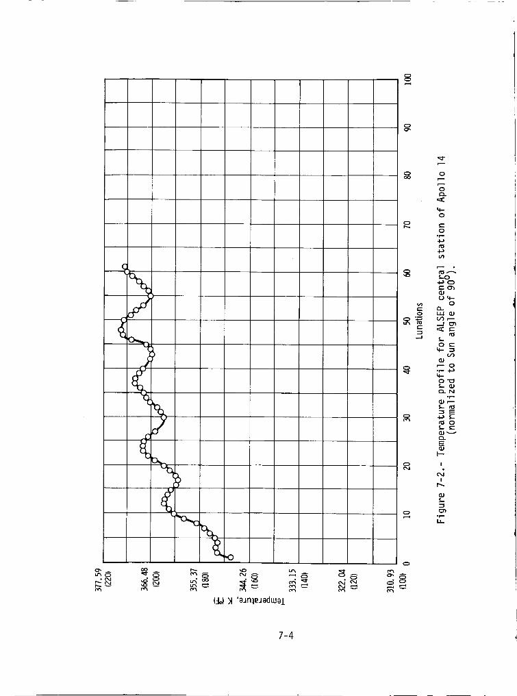
,,o.o
,,o
(-to))t 'aJnleJaduJal
0
0
C:
...J
0
0
0
4..
0
0°r-
_-O
.._O
('-C_
Uu,.-
O
Or} ,---
•::I:('-
O L'-
4-.
O,r.-
4..O"_
¢"_ N
-r-
_ ,..-.
E
OL
C)..
E
I
d!
",1
,r=,
7-4
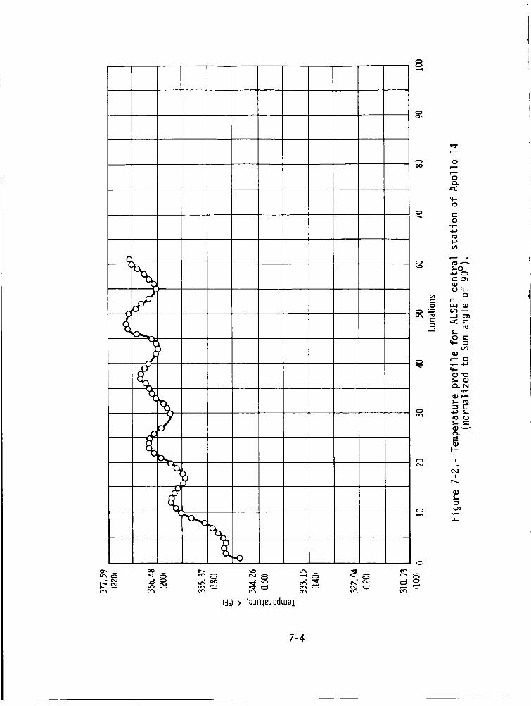
8
0
%
"(3
r..,.- e.4 _ u'_ °° _ "_I"._ _ ...o _ i..t_ ,-'_ ,......4
(%))1 'eJnleJedweL
o0o
o
o
o
t-"
o
o
o
o
o
o
7-4
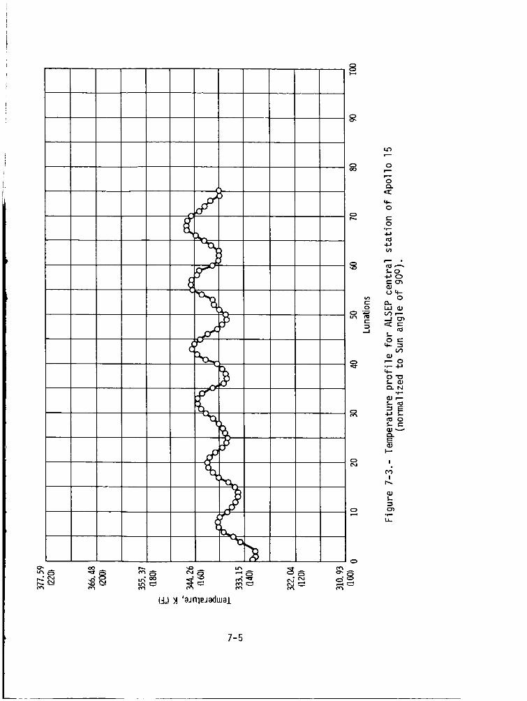
8
_R
o',,c, ar,C e,J
co i',,...
>
(._r%
(_-Io)_A 'aJnleJadtual
_a
oo
o
t-
0f...
%Q..
4..0
c-"0
.r-4-)n:l
4-bu3
LO
Ill(..)4-
O
(._ r..-
O e.-
_ O°r- 4-_
O'_
_..N°r.-
"I E
_ e-
E
I-.--
!
d!
P_
°r.-
7-5
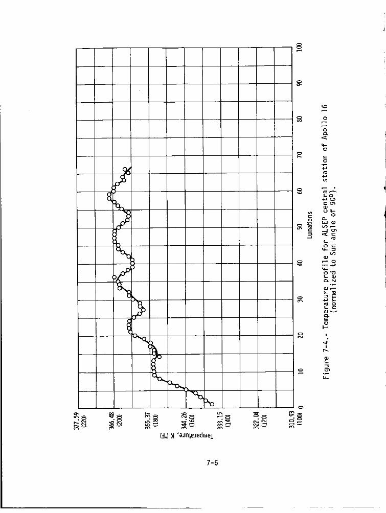
8
O'.
_8
S8
>
L-_,8 N8
(-Io))1 'aJn]sJadwal
_8
o ocX)
o
4-o
r_. c-
O°r-
,'_ •s-o
_ u4- o
--..I _
O e'-
m
_ r-- O'_ °r- 4-J
4--
O"_
e'_ N0I'D
I_ r"-
f,- tO
_ ""J E
tO O
e_
E
!
S,.
_ °r,-
7-6
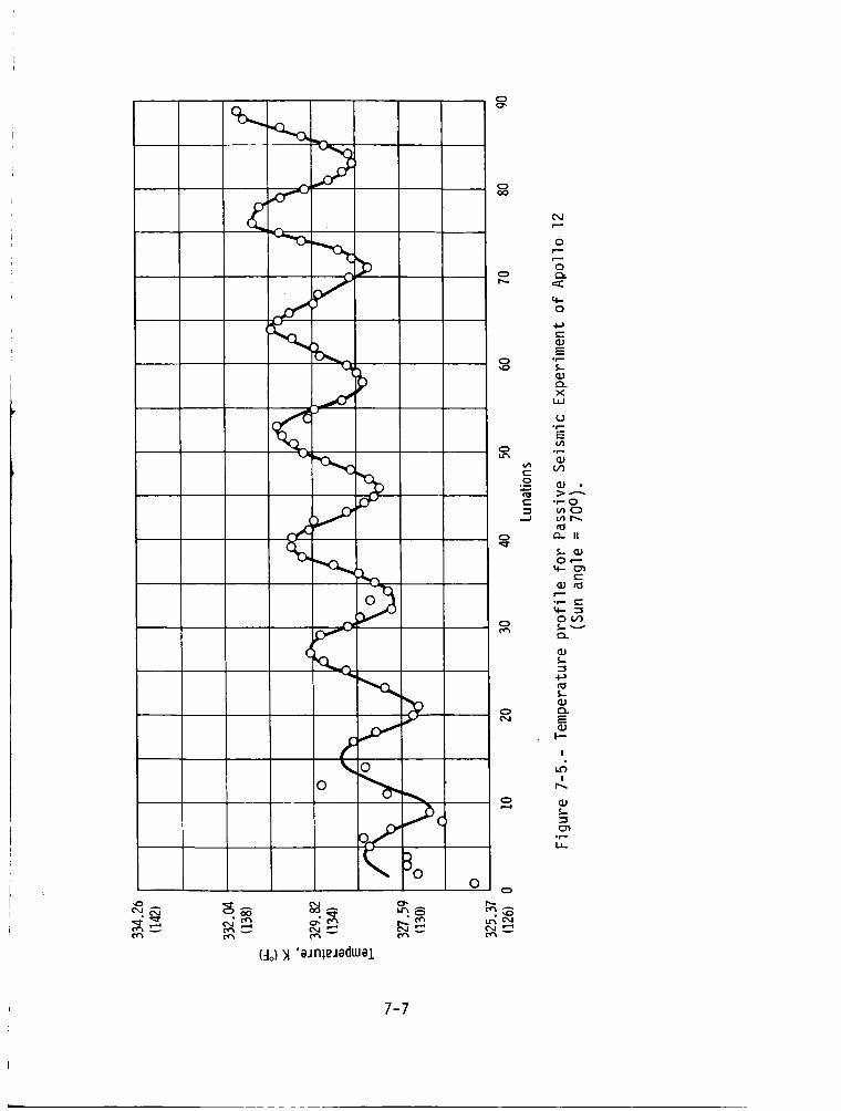
<
<_-o..c
7
o<%>_°_3°
¢_ o _oo_ Lr_ 8_ _ i_.e I_
(-Io))1 'aJnleJadwal
o',
o
r-'-
o
3
q-0
c--_J
E
X
U.r'-E
u-, "_
e" .e.- 0_ mO
Or--
e-"
°r'- f"
m
e,a N
I---
!
I
*r',-
0o
7-7
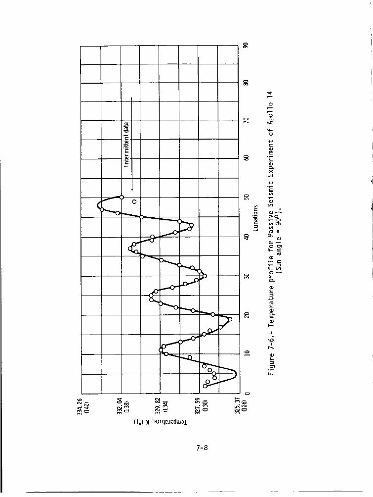
(4°))1 'aJnieJadwal
7-8

Cr,
L
..----0q
v
(:1o)_1 'aJFl_,eJadmal
oo
0
,,o
0
o
t'-
,-.I
Q
0e--,,
0Q..
0
t-G.JE
"r"
XtJJ
U°r-E
"TJc_
_O
e_
4- c-
E
I--
!
!P_
.r-LL.
7-9
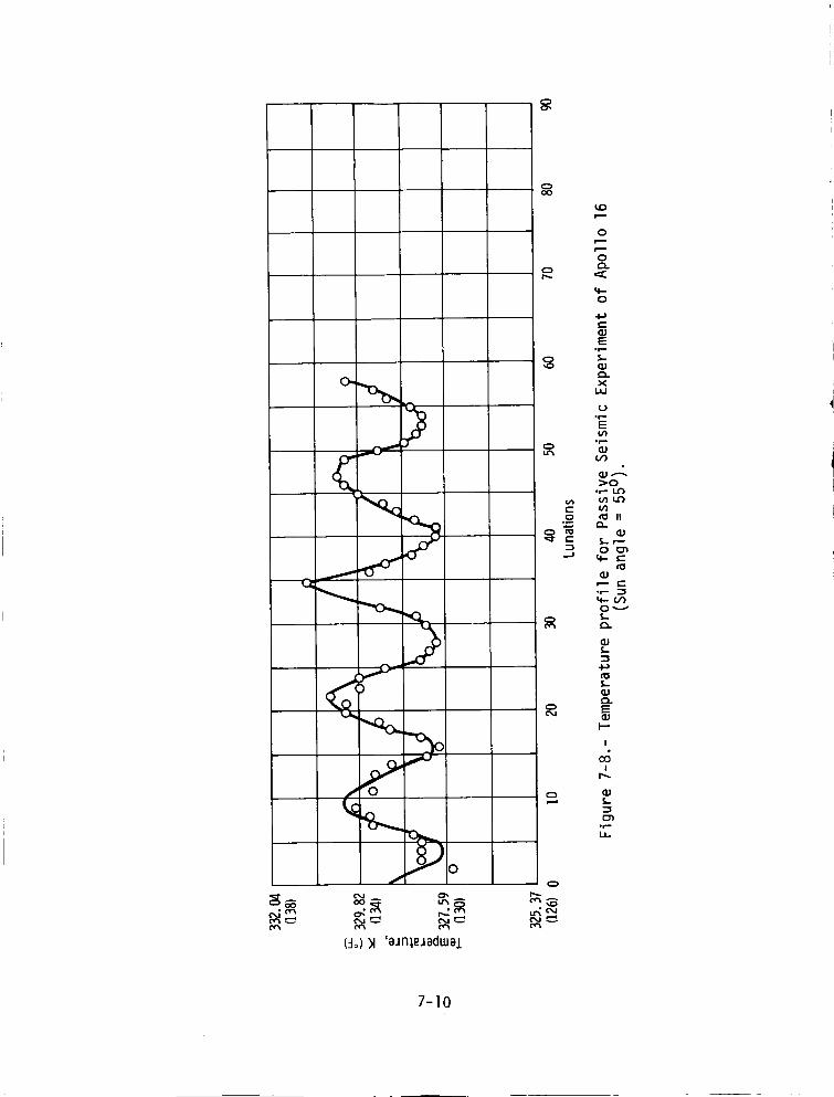
o',,
<_. r...-
(_-Io))1 'aJnlRJadwaJ.
oo
0
0C:1.
O
t-
E
"r_
X
U°r,-E
01.=,
_O
_ mmo n:S II:,_ O.to (1,1
"-_ O__1 4-
tOq.)
of_4-(1)
LqJQ.E
CM (1.1I--"
I
d!
0r.-
_N
7-10
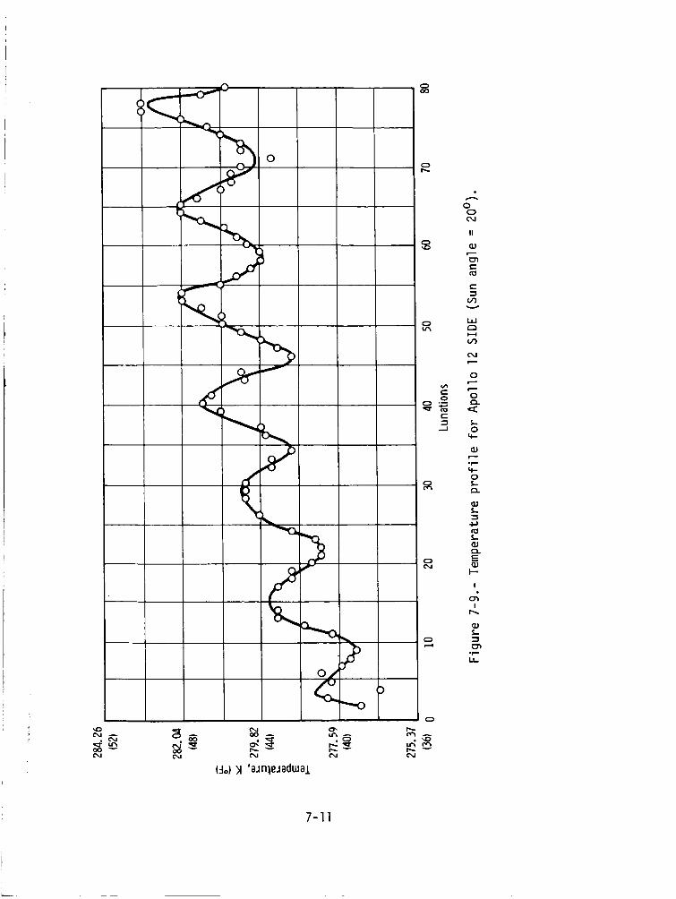
N A A O0 A
(-Io))1 'aJn3,eJadLue.l.
7-11
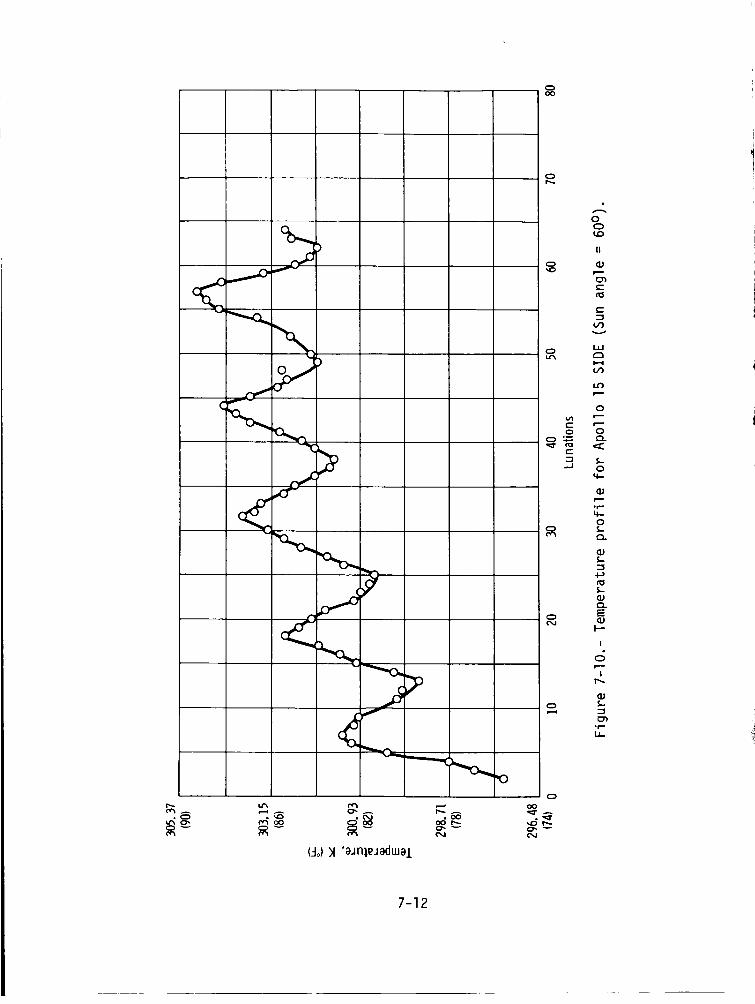
oo
\
°00O0
(-Iol)1 'aJn]eJadwel
0
¢...
...J
N
_r°_-
0
II
e"
I--I
V_
0
0
0
q--
_J
• r _u,..0S,-
Q..
L
S,-
_J
E
I--"
I
I
°r-
U-
7-12
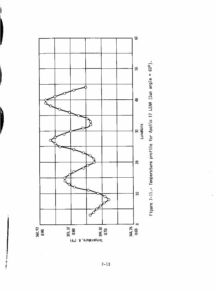
P,,,,, N
o-_. _oo o,'"
(-Io))1 'eJnieJedwal
Q",¢1"
00,.0
II
OJ4.--.
C
e-
c,O
LI.I,.--I
0c.,J
e,J
0
0.o a.
t--.-_
•--J 04-
(3Jpi..r-.4-0
OJ
tOL_J,,-,,E
I--.
I
rI.
L
°r'-
7-13
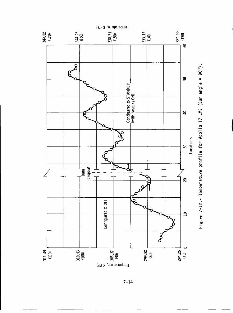
_8
0',
<
_80 0
(=1o))1'eJ nl.ejaduJe.I.
A
oo
N
7-14
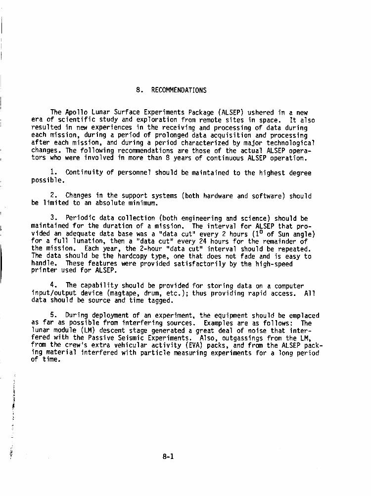
8. RECOMMENDATIONS
The Apollo Lunar Surface Experiments Package (ALSEP) ushered in a newera of scientific study and exploration from remote sites in space. It also
resulted in new experiences in the receiving and processing of data during
each mission, during a period of prolonged data acquisition and processingafter each mission, and during a period characterized by major technological
changes. The following recommendations are those of the actual ALSEP opera-tors who were involved in more than 8 years of continuous ALSEP operation.
1. Continuity of personnel should be maintained to the highest degreepossible.
2. Changes in the support systems (both hardware and software) shouldbe limited to an absolute minimum.
3. Periodic data collection (both engineering and science) should be
maintained for the duration of a mission. The interval for ALSEP that pro-
vided an adequate data base was a "data cut" every 2 hours (10 of Sun angle)for a full lunation, then a "data cut" every 24 hours for the remainder ofthe mission. Each year, the 2-hour "data cut" interval should be repeated.
The data should be the hardcopy type, one that does not fade and is easy tohandle. These features were provided satisfactorily by the high-speedprinter used for ALSEP.
4. The capability should be provided for storing data on a computer
input/output device (magtape, drum, etc.); thus providing rapid access. Alldata should be source and time tagged.
5. During deployment of an experiment, the equipment should be emplacedas far as possible from interfering sources. Examples are as follows: The
lunar module (LM) descent stage generated a great deal of noise that inter-fered with the Passive Seismic Experiments. Also, outgassings from the LM,from the crew's extra vehicular activity (EVA) packs, and from the ALSEP pack-
ing material interfered with particle measuring experiments for a long periodof time.
±
8-1
9. BIBLIOGRAPHY
Bendix Corporation: Bendix Technical Journal, vol. 4, Summer-Autumn1971.
Bendix Corporation: Apollo 16 ALSEPArray D Flight SystemFamiliarizationManual. NASACR-128924,1971.
Bendix Corporation: Apollo Lunar Surface ExperimentsPackage(Monthly Prog-ress Report). NASACR-115455,1972.
Bendix Corporation: Apollo Lunar Surface ExperimentsPackage(Monthly Prog-ress Report). NASACR-115577,1972.
Bendix Corporation: Apollo Lunar Surface ExperimentsPackage(Monthly Prog-ress Report). NASACR-115738,1972.
Bendix Corporation: Apollo Lunar Surface ExperimentsPackage(Monthly Prog-ress Report). NASACR-115739,1972.
Bendix Corporation: Apollo Lunar Surface ExperimentsPackage(Monthly Prog-ress Report). NASACR-128580,1972.
Bendix Corporation: Apollo Lunar Surface ExperimentsPackage(Monthly Prog-ress Report). NASACR-128597,1972.
Bendix Corporation: Apollo Lunar Surface ExperimentsPackage. Apollo 17ALSEP(Array E) Familiarization CourseHandout. NASACR-128636,1972.
Bendix Corporation: ALSEPArrays A, B, C, andA-2. Lunar Surface Explora-tion Instrument Specifications (Final Report). NASACR-134202,1973.
Berg, O. E.; Richardson, F. F.; Auer, S.; and Rhee, J. W.: Preliminary Re-sults of a CosmicDust Experiment on the Moon. Geophys.Res. Letters, vol.1, Nov. 1974, pp. 289-290.
Chute, J., Jr.; Clark, S. P.; et al.: Apollo 13 Lunar Heat Flow Experiment.Science, vol. 168, 1970, pp. 211-217.
Dorman,J.; Duennebier, F.; et al.: Seismic Data FromMan-MadeImpacts onthe Moon. Science, vol. 170, 1970, pp. 620-626.
Dyal, P.; Parkin, C. W.; and Sonett, C. P.: Lunar Surface Magnetometer.IEEETransactions on GeoscienceElectronics, vol. GE-8, 1970, pp. 203-215.
D I ._i
Dyal, P.; Parkin, C. W.; and Cassen, P.: Surface Magnetometer Experiments -Internal Lunar Properties and Lunar Field Interactions With the SolarPlasma. Lunar Science Conference, 3rd, Houston, Tex., January 10 to 13,
1972, Proceedings, vol. 3, MIT Press (Cambridge, Mass.), 1972, pp. 2287-2307.
Dyal, P.; and Gordon, D. I:Electrical and Electronics
D.C., Apr. 24 to 27, 1973.)
Sept. 1973, pp. 226-231.
Lunar Surface Magnetometers. (Institute of
Engineers, Intermag Conference, Washington,IEEE Transactions on Magnetics, vol. Mag-9,
Dyal, P.; Parkin, C. W.; and Daily, W. D.: Surface Magnetometer Experiments.Internal Lunar Properties. NASA TM X-62278, 1973.
Eason, R. L.: Apollo Experience Report, Apollo Lunar Surface ExperimentsPackage Data Processing System. NASA TN D-7781, 1974.
Eichelman, W. F.; Lauderdale, W. W.: Apollo Scientific Experiments DataHandbook. NASA TM X-58131, 1974.
Freeman, J. W., Jr.: Energetic Ion Bursts on the Nightside of the Moon. J.
Geophys. Res., vol. 77, Jan. 1, 1972, pp. 239-243.
Freeman, J. W., Jr.: Suprathermal Ion Detector Results From Apollo Missions.
Paper presented at COSPAR, Plenary Meeting, 15th, Madrid, Spain, May 10 to
24, 1972.
Freeman, J. W., Jr.; Fenner, M. A.; et al.: Suprathermal Ions Near the Moon.
(International Union of Geophysics and Geodesy, General Assembly, 15th,Moscow State University, Moscow, USSR, July 30 to Aug. 14, 1971.) Icarus,
vol. 16, Apr. 1972, pp. 328-338.
Freeman, J. W., Jr.; Hills, H. K.; and Vondrak, R. R.: Water Vapor, WhenceComest Thou. Lunar Science Conference, 3rd, Houston, Tex., January 10 to
13, 1972, Proceedings, vol. 3, MIT Press (Cambridge, Mass.), 1972, pp.2217-2230.
Freeman, J. W., Jr.; Fenner, M. A.; and Hills, H. K.: Electric Potential ofthe Moon in the Solar Wind. J. Geophys. Res., vol. 78, Aug. 1, 1973, pp.4560-4567.
Freeman, J. W., Jr.; Fenner, M. A.; and Hills, H. K.: The Electric Potentialof the Moon in the Solar Wind. Photon and Particle Interactions With Sur-
faces in Space; Proceedings of the Sixth ESLAB Symposium, Noordwijk,Netherlands, Sept. 26 to 29, 1972. D. Reidel Publishing Co., 1973, pp.
363-368; Discussion, p. 368.
Freeman, J. W., Jr.; Hills, H. K.; Lindeman, R. A.; and Vondrak, R. R.:Observations of Water Vapor Ions at the Lunar Surface. The Moon, vol. 8,
July-Aug. 1973, pp. 115-128.
9-2
i
Freeman, J. W.; and Ibrahim, M.: Lunar Electric Fields, Surface Potential
and Associated Plasma Sheaths. Lunar Science Institute, Conference on In-
teractions of the Interplanetary Plasma With the Modern and Ancient Moon,
Lake Geneva, Wis., Sept. 30 to Oct. 4, 1974. The Moon, vol. 14, Sept.1975, pp. 103-114.
Goldstein, B. E.: Observations of Electrons at the Lunar Surface. J.
Geophys. Res., vol. 79, Jan. 1, 1974, pp. 23-35.
Harris, R. S., Jr.: Apollo Experience Report, Thermal Design of Apollo LunarSurface Experiments Package. NASA TN D-6738, 1972.
Hinners, N. W.; and Mason, P. V.: The Apollo 17 Surface Experiments. Astro-naut. & Aeronaut., vol. 10, Dec. 1972, pp. 40-54.
Hoffman, J. H.; and Hodges, R. R., Jr.: Molecular Gas Species in the LunarAtmosphere. Lunar Science Institute, Conference on Interactions of the In-
terplanetary Plasma With the Modern and Ancient Moon, Lake Geneva, Wis.,Sept. 30 to Oct. 4, 1974. The Moon, vol. 14, Sept. 1975, pp. 159-167.
Johnson, F. S.; Carroll, J. M.; and Evans, D. E.: Vacuum Measurements on the
Lunar Surface. (International Vacuum Congress, 5th, Boston, Mass., Oct.11 to 15, 1971.) J. Vac. Sci. & Tech., vol. 9, Jan.-Feb. 1972, pp. 450-456.
Keihm, S. J.; Peters, K.; Langseth, M. G.; and Chute, J. L., Jr.: Apollo 15Measurement of Lunar Surface Brightness Temperatures - Thermal
Conductivity of the Upper 1.5 Meters of Regolith. Earth Planet. Sci.Letters, vol. 19, no. 3, July 1973, pp. 337-351.
Lammlein, D. R.; Latham, G. V.; et al.: Lunar Seismicity, Structure, andTectonics. Rev. Geophys. Space Phys., vol. 12, Feb. 1974, pp. 1-21.
Langseth, M. G., Jr.; Drake, E. M.; Nathanson, D.; Fountain, J. A.: Develop-ment of an In Situ Thermal Conductivity Measurement for the Lunar Heat Flow
Experiment. Thermal Characteristics of the Moon. MIT Press, (Cambridge,Mass.), 1972, pp. 169-204.
Latham, G. V.: Lunar Seismology. EOS, vol. 52, 1971, pp. IUGG 162-IUGG 165.
Manka, R. H.; and Michel, F. C.: Lunar Ion Flux and Energy. Photon and Par-ticle Interactions With Surfaces in Space; Proceedings of the Sixth ESLAB
Symposium, Noordwijk, Netherlands, Sept. 26 to 29, 1972. D. ReidelPublishing Co., 1973, pp. 429-441; Discussion, pp. 441 and 442.
Mark, N.; and Sutton, G. H.: Lunar Shear Velocity Structure at Apollo Sites12, 14, and 15. J. Geophys. Res., vol. 80, Dec. 10, 1975, pp. 4932-4938.
9-3
Medrano,R. A.; Freeman,J. W., Jr.; Vondrak, R. R.; and Hills, H. H.: Obser-vation of a Driver Gas-Tangential Discontinuity. International Symposiumon Solar-Terrestrial Physics, SaoPaulo, Brazil, June 17 to 22, 1974,Proceedings, vol. 1, SaoJose DosCampos,Brazil, Instituto de PesquisasEspaciais, 1974, pp. 204-218.
National Aeronautics and SpaceAdministration: Apollo 11 Preliminary ScienceReport. NASASP-214, 1969.
National Aeronautics and SpaceAdministration: Apollo 12 Preliminary ScienceReport. NASASP-235, 1970.
National Aeronautics and SpaceAdministration: Apollo 14 Preliminary ScienceReport. NASASP-272, 1971.
National Aeronautics and SpaceAdministration: Apollo 15 Mission Report.NASATMX-68394, 1971.
National Aeronautics and SpaceAdministration: Apollo 15 Preliminary ScienceReport. NASASP-289,1972.
National Aeronautics and SpaceAdministration: Apollo 16 Preliminary ScienceReport. NASASP-315, 1972.
National Aeronautics and SpaceAdministration: Apollo 17 Preliminary ScienceReport. NASASP-330, 1973.
Nelms,W. L.; and Schwartz, W.: Mechanical Aspects of the Lunar Surface Mag-netometer. AerospaceMechanisms,Part A - General Applications, G. G.Herzl, ed., vol. I, pp. 463-468.
Neugebauer,M.; Snyder, C. W.; Clay, D. R.; and Goldstein, B. E.: SolarWindObservations on the Lunar Surface With the Apollo-12 ALSEP. Planet.& SpaceSci., vol. 20, Oct. 1972, pp. 1577-1591.
Orsag, J. W.; and Vogt, R. A.: Cold-Cathode-GageExperiment Electronics Pack-age. Thermal Shield Design Development. NASATMX-72057, 1968.
Prosser, D.L.: SNAP-27on the Moon. Isotopes & Radiation Technology, vol.7, 1970, pp. 443-447.
Reasoner,D. L.; and Burke, W. J.: Characteristics of the LunarPhotoelectron Layer in the GeomagneticTail. J. Geophys.Res., vol. 77,Dec. 1, 1972, pp. 6671-6687.
Reasoner, D. L.; and Burke, W. J.: Direct Observation of the LunarPhotoelectron Layer. Lunar Science Conference, 3rd, Houston, Tex., January10 to 13, 1972, Proceedings, vol. 3, MIT Press, (Cambridge, Mass.), 1972,pp. 2639-2654.
9-4
Reasoner, D. L.; and Burke, W. J.: Measurement of the Lunar Photoelectron
Layer in the Geomagnetic Tail. Photon and Particle Interactions With Sur-faces in Space; Proceedings of the Sixth ESLAB Symposium, Noordwijk,Netherlands, Sept. 26 to 29, 1972. D. Reidel Publishing Co., 1973, pp.
369-386; Discussion, pp. 386 and 387.
Remini, W. C.; and Grayson, J. H.: SNAP-27/ALSEP Power Subsystem Used in
the Apollo Program. Energy 70; Proceedings of the Fifth IntersocietyEnergy Conversion Engineering Conference, Las Vegas, Nev., Sept. 21 to 25,1970, vol. 2. Hinsdale, Ill., American Nuclear Society, 1972, pp. 13-10 to13-15.
Rhee, J. W.; Berg, O. E.; and Wolf, H.: Electrostatic Dust Transport andApollo 16 LEAM Experiment. Space Research XVII; Proceedings of the Open
Meetings of Working Groups on Physical Sciences, June 8 to 19, 1976, andSymposium on Minor Constituents and Excited Species, Philadelphia, Pa.,
June 9 and 10, 1976. Pergamon Press, 1977, pp. 627-629.
Rice University: The Apollo Lunar Surface Experiment Package Suprathermal
Ion Detector Experiment - Bibliographies (Final Report). NASA CR-144544,1975.
Schneider, H. E.; and Freeman, J.W.: Energetic Lunar Nighttime Ion Events.Lunar Science Institute, Conference on Interactions of the InterplanetaryPlasma With the Modern and Ancient Moon, Lake Geneva, Wis., Sept. 30 to
Oct. 4, 1974. The Moon, vol. 14, Sept. 1975, pp. 27-33.
Stanford University: Apollo 14 and 16 Active Seismic Experiments, andApollo 17 Lunar Seismic Profiling (Final Report). NASA CR-147760, 1976.
9-5
• !

_i/"
APPENDIX A
LIST OF ACRONYMS
ALSEP
APMASE
BPI
CPLEEDACDSS
DTREM
EASEP
EPSEUVEVAFM
GSFCHF
HFEJPL
JSCLEAMLMLMS
LPX, LPY,LPZ
LSGLSM
LSPEMOD
MSFNMSFNOMNSSDCPCU
PDR
PDUPI
PSERF
RSDPRTGSCAMASIDE
SMEAR
Apollo Lunar Surface Experiments Packageautomatic power management
Active Seismic Experiment or ALSEP Senior Engineerbits per inchCharged Particle Lunar Environment Experiment
digital-to-analog converterdata subsystem
dust thermal radiation engineering measurement (dustdetector)
Early Apollo Scientific Experiment Packageelectrical power subsystemextreme ultraviolet
extra vehicular activityfrequency modulation
NASA Goddard Space Flight Center
high frequencyHeat Flow ExperimentNASA Jet Propulsion Laboratory
NASA Lyndon B. Johnson Space Centerlunar ejecta and meteoriteslunar module
lunar mass spectrometerlong period x-, y-, and z-axes components (refers to PassiveSeismic Experiment)
lunar surface gravimeter
lunar surface magnetometerLunar Seismic Profiling Experimentmodule
Manned Space Flight NetworkManned Space Flight Network Operation ManagerNational Space Science Data Center
power conditioning unit
power dissipation resistorspower distribution unit
Principal InvestigatorPassive Seismic Experiment
radio frequencyremote site data processor
radioisotope thermoelectric generatorswitching, conferencing, and monitoring arrangementSuprathermal Ion Detector ExperimentSPAN mission evaluation action request
• . =-= . . _

SODBSPAN
SWSTTY
UTVLBI
spacecraft operational data book
spacecraft analysissolar wind spectrometer
teletypeuniversal time
very long base interferometer
A-2
1. Report No.RP-1036
4. Title and Subtitle
ALSEP Termination Report
2. Government Acc_sion No.
7. A_thor(s)$_mes R. Bates, Lyndon B. Johnson Space Center; W. W. Lauder-
dale, General Electric Co.; and Harold Kernaghan, Kentron
3. Recipient's Catalo_3 No.
5. Report Date
April 1979
6. Pe_orming Organization Code
8. Performing Organization Report No.
S-480
International, Inc. 10. Work Unit No.
9. PerformingOrganization Name and Address
Lyndon B. Johnson Space Center
Houston, Texas 77058
12. S_nsoring Aga_V Narne_d Addr_s
National Aeronautics and Space Administration
Washington, D.C. 20546
"i5. _p_ementary Not_ '"
914-40-73-01-72
11. Contractor Grant No.
13. Type of Report and Period Cove_ed
Reference Publication
14. Sponsoring A_¥"_de
This final report on the Apollo Lunar Surface Experiments Package (ALSEP) was prepared when
support operations were terminated September 30, 1977, and NASA discontinued the receiving
and processing of scientific data transmitted from equipment deployed on the lunar surface.
The ALSEP experiments (Apollo ii to Apollo 17) are described and pertinent operational
history is given for each experiment, The ALSEP data processing and distribution are de-
scribed together with an extensive discussion on archiving. Engineering closeout tests and
results are given, and the status and configuration of the experiments at termination are
documented. Significant science findings are sun,narized by selected investigators.
Significant operational data and recommendations are also included.
17. Key Words(Suggest_ by Authori$))
Lunar science ASTP
Lunar exploration Space sciences
Lunar environment
Moon
Apollo
18. Distribution Statement
STAR Subject Category
88 (Space Sciences)