Embed Size (px)
Citation preview
Non-linear Effects in MEMS Tunable Bandstop Filters
Xiaoguang Liu∗, Eric Naglich†, and Dimitrios Peroulis†
∗Department of Electrical and Computer Engineering, Davis Millimeter-Wave Research Center,University of California, Davis, 95616, USA.
†School of Electrical and Computer Engineering, Purdue University, West Lafayette, 47906, [email protected], [email protected], [email protected]
Abstract—This paper provides the first study of electrome-chanical non-linearities of MEMS tunable bandstop filters. Thestudied non-linearity sets a limit on the power handling capabilityof such filters. A two-pole MEMS tunable evanescent-mode (EVA)bandstop filter is fabricated and measured to validate the non-linear circuit modeling. Good agreement is observed betweenmeasurement and modeling. The fabricated tunable bandstopfilter exhibits more than 2 W power handling capability around2 GHz. To the authors’ best knowledge this is the highestpower handling reported for an L-band bandstop filter basedon evanescent-mode cavity resonators.
Index Terms—RF-MEMS, tunable filter, evanescent-mode res-onator, non-linearity, power handling
I. INTRODUCTION
Tunable bandstop filters are important components for re-configurable RF/microwave systems in today’s crowded fre-quency spectrum. Bandstop filters can be used to suppressinterferers which could intentionally or unintentionally satu-rate nearby receivers. Bandstop filters could also be used toreject narrow band signals for wideband systems such as ultra-wideband systems. Making bandstop filters tunable adds totheir flexibility by enabling them to suppress dynamic signalsat different frequencies.
Several tunable bandstop filter technologies have recentlybeen demonstrated [1]-[5]. In particular, highly-tunable band-stop filters based on tunable evanescent-mode (EVA) cavityresonators have been demonstrated to achieve high tuningrange, high isolation (> 90 dB) and dynamically adjustablebandwidth [6].
To assess the potential applications of such filters, it is criti-cal to investigate their power handling capabilities. Previouslythe authors examined the power handling capabilities of tun-able bandpass EVA filters and identified the electromechanicalnon-linearities of the tuning elements as one limiting factor[7], [8]. This paper builds upon our previous investigationand focuses on the electromechanical non-linearities in tunablebandstop EVA filters.
II. ELECTROMECHANICAL NON-LINEARITY OF THEMEMS DIAPHRAGM TUNER
In a highly-loaded EVA tunable resonator, there is a highelectric field between the top wall and the capacitive post(Fig. 1-a). This electric field, although alternating in direction,introduces a net attractive force between the top wall and thepost. When the top wall is flexible, as in the case of MEMS
1 1n1n2
CrLrRu
ωω0
S21
n
Cr
Lr
Ru
E
ωω0
S21
1
IncreasingRF Power
IncreasingRF Power
Inpu
t
Out
put
Input Output
CapacitivePost
Highly-loaded Evanescent-mode Cavity
(a)
(b) (c)
(d) (e)
Fig. 1. (a) Capacitively loaded EVA cavity resonator; (b) Equivalent circuitof a bandpass coupled tunable EVA resonator; (c) Non-linear frequencyresponses of bandpass EVA resonator; (d) Equivalent circuit of a bandstopcoupled tunable EVA resonator; (e) Non-linear frequency responses of band-stop EVA resonator.
tunable resonators, this force will deflect the top wall towardsthe post, causing non-linear responses that set a limit to thepower handling capability of such tunable resonators.
Previously the authors studied such non-linearities for band-pass resonators/filters [7], [8]. In a bandpass structure, RFsignal travels through the resonator (Fig. 1-b) between theinput and output coupling structures. The influence of the RFpower on the frequency response is conceptually shown inFig. 1-c. With moderate RF power, the resonant frequency isdecreased, and the frequency response becomes asymmetric.With high enough RF power, bifurcation instability occursand an abrupt discontinuity in the frequency response canbe observed. [8] presented a non-linear varactor model of
n
Cr
Lr
Ru
1
n
Cr
Lr
Ru
1
λ4
Input Output
(a)
(b)
Fig. 2. (a) Circuit model for a two-pole tunable bandstop filter; (b) Simulatedlarge signal response of a two-pole bandstop filter.
such electromechanical non-linearity of tunable bandpass EVAresonators/filters.
Using the above mentioned non-linear model, one caninvestigate the same electromechanical non-linearity in band-stop structures, such as the bandstop resonator in Fig. 1-d. It is discovered that the frequency response of bandstopstructures follows a similar trend as the bandpass structures.At moderate RF power, the frequency response bends towardslower frequencies; at sufficiently high RF power, the samebifurcation instability can be observed.
Fig. 2 shows the simulated non-linear frequency responsefor a two-pole tunable bandstop filter at 2 GHz (with Cr =0.58 pF, Lr = 10.95 nH, Ru = 47 kΩ, and n = 5.7). Theseparameters are extracted from simulations and measurementsin Section III. Shown in Fig. 2-a, the filter is designed bycoupling two tunable EVA resonators, separated by a quarterwavelength, to a transmission line that directly connects theinput and output. It is observed that the stopband centerfrequency decreases from 1.985 GHz to 1.98 GHz as the RFpower increases from 0 dBm to 35 dBm. The 10-dB stopbandbandwidth increases from 40 MHz to 65 MHz and the mid-band rejection decreases from 18 dB to 15 dB.
III. EXPERIMENTAL VALIDATION
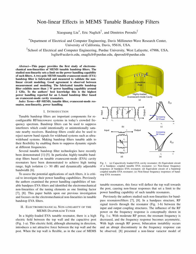
A two-pole MEMS tunable bandstop filter is designed andfabricated to validate the modeling. Fig. 3 shows the band-stop filter structure and pictures of the fabricated filter. Thefilter consists of two laminated Rogers microwave substrateboards. The top board (RO4350B) contains the feedline andcoupling apertures. The bottom board (TMM-3) contains theevanescent-mode resonant cavities. The cavity boundaries aredefined by metalized vias as labeled in Fig. 3. Tuning is
MEMS Diaphragm Tuners
TMM-3
CouplingApertures
Transmission LineInput
Output
50 mm
20 mm
1.8 mm 6.2 mm
3.175 mm
(a)
(b)
Cavities
MEMS Diaphragm Tuners
RO4350B
0.762 mm
Fig. 3. (a) Structure design of the MEMS tunable bandstop filter; (b)Fabricated tunable bandstop filter.
S21
S11
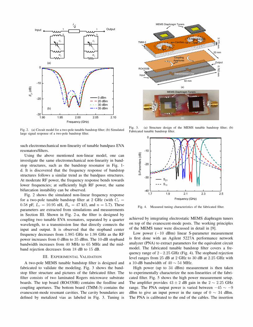
Fig. 4. Measured tuning characteristics of the fabricated filter.
achieved by integrating electrostatic MEMS diaphragm tunerson top of the evanescent-mode posts. The working principlesof the MEMS tuner were discussed in detail in [9].
Low power (−10 dBm) linear S-parameter measurementis first done with an Agilent 5227A performance networkanalyzer (PNA) to extract parameters for the equivalent circuitmodel. The fabricated tunable bandstop filter covers a fre-quency range of 2−2.25 GHz (Fig. 4). The stopband rejectionlevel ranges from 25 dB at 2 GHz to 30 dB at 2.25 GHz witha 10-dB bandwidth of 40 ∼ 54 MHz.
High power (up to 34 dBm) measurement is then takento experimentally characterize the non-linearities of the fabri-cated filter. Fig. 5 shows the high power measurement setup.The amplifier provides 43 ± 2 dB gain in the 2 ∼ 2.25 GHzrange. The PNA output power is varied between −45 ∼ −9dBm to give an input power in the range of 0 ∼ 34 dBm.The PNA is calibrated to the end of the cables. The insertion

Amplifier Circulator
DUT
Attenuator
NetworkAnalyzer
Fig. 5. Measurement setup for large signal measurement of the tunablebandstop evanescent-mode filter.
IncreasingRF Power
Fig. 6. Measured large-signal response of the fabricated tunable bandstopfilter at increasing RF power levels.
losses of the circulator, attenuator and cables are measuredseparately and subtracted from the measurement to determinethe actual power going through the resonator.
Fig. 6 shows the stopband responses of the fabricatedtunable bandstop filter with increasing RF power levels. Goodagreement is observed with simulation. The frequency re-sponse at 34 dBm shows a hint of the instability observedpreviously in the bandpass filters [8]. It is to be noted thatthese measurements are taken at the lower end of the tuningrange and represent the worst-case power handling capability.When the filter is tuned to higher frequencies, the gap betweenthe diaphragm tuner and the post increases, therefore furtherincreasing the power handling capability.
It is worth noting that under moderate RF power, theresonant frequency shift and frequency response distortion canbe compensated by changing the bias voltages on the MEMStuners. Fig. 7 shows an example. With an input power of 33dBm, the stopband frequency shifts by 5 MHz and the 10-dBbandwidth changes from 40 MHz to 53 MHz. By applying anadditional 1.3 V on the bias electrodes, the frequency responsecan be pulled back as shown in Fig. 7. The compensatedstopband response closely resembles the original response.
IV. CONCLUSION
This paper provides the first investigation of the RF-inducedelectromechanical non-linearity in MEMS tunable bandstopfilters. Such non-linearity is identified as one limiting factor
0 dBm
33 dBm Compensated
33 dBm
Fig. 7. Measured large-signal response with and without bias compensation.
of the power handling capability of MEMS tunable bandstopfilters. Circuit modeling accurately captures the non-linearresponse of such filters under high RF power. The modelingis validated by measurement of a two-pole tunable bandstopfilter with 2 W RF power.
V. ACKNOWLEDGEMENT
This work has been supported by DARPA under the PurdueMicrowave Reconfigurable Evanescent-Mode Cavity FiltersStudy. The views expressed are those of the author and donot reflect the official policy or position of the Departmentof Defense or the U.S. Government. Approved for PublicRelease, Distribution Unlimited.
REFERENCES
[1] D. R. Jachowski and C. Rauscher, “Frequency-agile bandstop filter withtunable attenuation,” IEEE MTT-S Int. Microwave Symposium Digest,pp.649-652, Boston, MA, June 2009.
[2] A. I. Abunjaileh and I. C. Hunter, “Tunable combline bandstop filter withconstant bandwidth,” IEEE MTT-S Int. Microwave Symposium Digest,pp.1349-1352, Boston, MA, June 2009.
[3] E. J.Naglich, J. Lee, D. Peroulis, and W. J. Chappell, “Tunable, substrateintegrated, high Q filter cascade for high isolation,” IEEE MTT-S Int.Microwave Symposium Digest, pp.1468-1471, Anaheim, CA, May 2010.
[4] I. Reines, S.-J. Park, G.M. Rebeiz, “Compact Low-Loss Tunable X -Band Bandstop Filter With Miniature RF-MEMS Switches,” IEEE Trans.Microwave Theory and Techniques, vol.58, no.7, pp.1887-1895, July2010.
[5] Y.-H. Chun, J.-S. Hong, P. Bao, T. J. Jackson, M. J. Lancaster, “BSTVaractor Tuned Bandstop Filter with Slotted Ground Structure”,
[6] J. Lee, E. J. Naglich, and W. J. Chappell, “Frequency Response Controlin Frequency-Tunable Bandstop Filters”,IEEE Microwave and WirelessComponents Letters, vol. 20, no. 12, pp. 669-671, Dec. 2010
[7] X. Liu, L. P. B. Katehi, W. J. Chappell, and D. Peroulis, “PowerHandling Capability of High-Q Evanescent-mode RF MEMS Resonatorswith Flexible Diaphragm”, 2009 Asia Pacific Microwave Conference,Singapore, Dec. 2009.
[8] X. Liu, L. P. B. Katehi, W. J. Chappell, and D. Peroulis, “Power Handlingof High-Q MEMS Tunable Evanescent-mode Resonators and Filters,”IEEE Transactions on Microwave Theory and Techniques, vol. 60, No.2, pp. 270-283, Feb. 2012
[9] X. Liu, L. P. B. Katehi, W. J. Chappell, and D. Peroulis, “High-Q TunableMicrowave Cavity Resonators and Filters using SOI-based RF MEMSTuners”, IEEE/ASME Journal of Microelectromechanical System, vol. 19,no. 4, pp. 774-784, Aug. 2010.


![Fabrication and characterization of nanocomposite-based ... · mirrors [6,7,8], reflective thin membrane [9], MEMS tunable gratings [10,11]) suffer of several drawbacks in terms](https://img.pdfslide.net/doc/110x75/5d5ad1bb88c99330748bc3cc/fabrication-and-characterization-of-nanocomposite-based-mirrors-678.jpg)


![IEEE MICROWAVE AND WIRELESS COMPONENTS ...arXiv:1805.03783v1 [eess.SP] 10 May 2018 IEEE MICROWAVE AND WIRELESS COMPONENTS LETTERS 1 Continuously Tunable Dual-mode Bandstop Filter Amir](https://img.pdfslide.net/doc/110x75/5e7375897f5291376d3d7de2/ieee-microwave-and-wireless-components-arxiv180503783v1-eesssp-10-may-2018.jpg)