Embed Size (px)
Citation preview

Novel method for underwater navigation aidingusing a companion underwater robot as a guiding
platformsVladimir Djapic1, Ðula Nad3, Gabriele Ferri1, Edin Omerdic2, Gerard Dooly2, Dan Toal2 and Zoran Vukic3
Abstract— This paper presents the results of multi-nationalcollaboration during the sea trial held in the coastal waters of LaSpezia, Italy, in the period 17 Oct. – 07 Nov. 2012. The trial wasperformed as one of the objectives of the program which has agoal to achieve the entire chain of Mine Countermeasures (MCM)using unmanned, robotic platforms. The focus of activities in thissea trial was to perform the last events of the mission: reacquisi-tion, identification and intervention using a pair of collaboratingunderwater vehicles. The trial’s objectives were to combine theexpertise and robotic systems from different partners and achievea mission of precise guiding of an inexpensive underwater vehicleto an underwater target using the navigation suite and controlsystem of a more capable underwater vehicle. The objectives wereaccomplished and the researchers’ opinion is that the extensionto multi-vehicle cooperation (one leader guiding several agents,or followers) is feasible given the test results.
I. INTRODUCTION
Most modern autonomous underwater vehicles (AUVs)provide an aided inertial system (AINS) as their navigationsolution. AINS systems are based around inertial measurementunit (IMU) aided by a Doppler velocity log (DVL), depthsensor and underwater or global positioning system [1]. Aidingsensors are needed to reduce the drift rate or periodically resetposition estimates. Modern INS systems are specified as beingcapable of heading drift rates of less than 0.01 deg/hr [2]. Highaccuracy comes with higher cost, which is acceptable for non-expendable AUVs, but is not desired for expendable (one-shot)unmanned underwater vehicles (UUVs), which are taken intoconsideration in this paper. Although the cost factor eliminatesthe complete AINS solution from the equation, a basic sensorsuite, e.g. compass and pressure sensor, remains as a minimalrequirement.
The main objective of the proposed system is for the UUVto follow a 3D path, therefore the basic sensor suite needs to beexpanded with position measurements. Higher frequency longbaseline (LBL) systems can offer sub-centimeter precision andupdate rates up to 10 Hz [3]. However, precise mooring of
This work was performed under the 2012 CMRE CPOW - ConsolidatedProgramme of Work, and supported by the Centre’s Visiting ResearcherProgramme. This work was also supported by Office of Naval Research Global(ONRG).
1 Centre for Maritime Research and Experimentation (CMRE), Viale S.Bartolomeo 400, La Spezia 19126, Italy.
2 Mobile & Marine Robotics Research Centre (MMRRC), Universityof Limerick (UL), Limerick, Ireland.
3 University of Zagreb, Faculty of Electrical Engineering and Comput-ing, LabUST - Laboratory for Underwater Systems and Technologies Unska3, Zagreb, Croatia.
LBL transponders is required. Alternatively, GPS intelligentbuoy (GIB) systems offer adequate performance without theneed for transponders to be precisely moored on the sea-floor[4]. On the other hand, transponder deployment and recoveryis still necessary. This issue can be resolved by using an ultrashort baseline (USBL) system on a support platform. Thedownside of a USBL system is performance degradation withhigher elevation angle, especially noticeable in shallow waters.
This paper presents our ongoing research and the resultsfrom recent sea trial of using a multibeam imaging sonarinstead of LBL/USBL systems for the purpose of UUVnavigation aiding. From the sonar image, UUV range andbearing relative to the sonar head can be measured, similarly toa USBL system. However, higher multibeam resolution offersbetter precision in comparison to USBL measurements. Thedownside is that the UUV has to remain in the sonar beam.This can be solved by mounting a sonar on a pan and tiltsystem or mounting it on a robot that can control all sixdegrees of freedom (DOF): translation in and rotation aboutthree perpendicular axes. With our approach, a mine interven-tion UUV can be small and inexpensive with a basic sensorsuite and an acoustic receiver for receiving measurementupdates obtained from the sonar image. In addition, the paperadvocates the potential of using collaborative autonomousvehicles in MCM scenarios. In the envisioned concept ofoperations, an AxV (surface or underwater) reacquires a mine-looking target using its imaging sonar. Immediately following,the AxV guides a low-cost mine intervention UUV carryinga payload to neutralize the target. Collaboration between thehighly capable AxV and the low-cost, hence less capable, mineneutralization UUV is viewed as an interesting research subjectin the field of mine reacquisition and neutralization since itcan potentially drastically reduce the overall MCM missiontimeline.
The paper is organized as follows. Section II introduces thepotential of using collaborative autonomous vehicles in minecountermeasures (MCM) scenarios and explains the system ofunmanned platforms that can be used in the intervention phaseof the MCM mission. The software integration between theLatis ROV and the autonomous guiding system is describedin Section III. Section IV present the sonar integration viaMOOS (Cross Platform Software for Robotics Research) im-plementation. Section V presents the results of our recent seatrial. Finally, Section VI contains the conclusions and potentialimpact of this work.
978-1-4799-0002-2/13/$31.00 ©2013 IEEE

II. SYSTEM OF COOPERATIVE MARITIME VEHICLES
The state-of-the-art would seem to suggest that all theabove-mentioned on-board sensors are necessary for accurateunderwater navigation with bounded positional error, if all therobots were working independently. In such a scenario, sucha highly capable suite of required on-board sensors (or in-water transponder placement operations) not only increases thecost of the individual robots and the total cost of meaningfuloperations, but also increases their footprint, leaving verylittle room for user-desired and user-defined payload modules,assuming the constraint that each individual robot continue tobe a one- or two-man portable, lightweight (∼ 50 kg) flexiblyfieldable system. We propose, instead, to have the UUVs workcooperatively, since their cooperation will allow for a reductionof the navigation-related footprint by leveraging state-of-the-art cooperative navigation algorithms, which Centre for Mar-itime Research and Experimentation (CMRE) and Universityof Zagreb (UNIZG) have already developed through existingcollaboration.
The CMRE is exploring various MCM approaches usingsquads of autonomous vehicles. A squad is a small group ofvehicles with complementary capabilities that most effectivelyachieve a mission through cooperative behavior. The simplestsquad consists of two vehicles. Current efforts focus oncost-effective neutralization (end-state driver) using a pair ofautonomous platforms: a highly capable autonomous surfaceand/or underwater vehicle and a low-cost, guided neutral-ization autonomous underwater vehicle. Therefore, the nextlogical step for vessels in MCM missions is to deploy multiple(two or more) vessels in an operating area with the expectationthat they will move about smartly such that they will be anasset to the authority responsible for securing the area orprotecting a particular asset. In this paper, the developmentof a Smart ROV / UUV system with improved autonomyand control. This approach is scalable and can be applied toother autonomous platforms. The Mobile & Marine RoboticsResearch Centre, Univ. of Limerick has offered to contribute tothe trial by bringing a capable, automated Remotely OperatedVehicle rated to 1500 m depth and a forward looking sonar thathas a range beyond that of the same type of sonar available atCMRE. The suggested teaming can demonstrate delivery of amine intervention vehicle to targets at significant depths andwith stand-off distances longer than CMRE can demonstratewith its assets. This should help convince the operationalcommunity of the effectiveness of the concept.
The concept of external system guidance proven at CMREhas involved the autonomous surface vehicle (ASV) reac-quiring a bottom target using high-resolution forward-lookingimaging sonar, and guiding the delivery vehicle to closeproximity of the target with minimal navigation correctioninformation (40 bits) sent via simplified acoustic modemevery 1-2 sec, (Fig. 1(a)). These corrections, that include therange and bearing to the UUV, are determined using sonarimage processing, (Fig. 1(b)). The proven idea, tested at threemajor NATO sea trials, is that the inexpensive unmanned
underwater vehicle (UUV) can be aided by a more capablesurface platform [5]. In this trial this idea has been extendedto 3D using an underwater robot as a guiding platform.
(a) Multibeam sonar guiding
(b) Multibeam sonar imagery
Fig. 1. External Guiding System
A. Smart ROV Latis
A smart Remotely Operated Vehicle, ROV Latis, is aprototype platform to test and validate OceanRINGS - a suit ofsmart technologies for subsea operations, developed at Mobile& Marine Robotics Research Centre, University of Limerick. Itis a next generation smart ROV with unique features, includingmultiple modes of operation, advanced 2D and 3D displays,intuitive, versatile and easy to use pilot interface and built-in fault-tolerant control system. With integrated state-of-the-art navigation sensors/instruments, the vehicle can achieveprecision navigation and subsea positioning. Other featuresinclude ROV DP in absolute earth-fixed frame or relativeto ship, high precision, robust speed/course controller withindependent heading control and improved ROV – ship link.ROV Latis was designed as a prototype test bed for challeng-ing operation environments in the ocean. ROV Latis sharesmuch with other state of the art ROVs as used in oceanengineering and ocean research. The vehicle also has manyfeatures not available in commercial ocean ROV technology[6]. With state of the art navigation sensors/instruments thevehicle can achieve precision navigation and positioning subsea. The navigation sensor suite includes a fiber optic gyrobased inertial navigation system with extended Kalman filterintegrated with aiding sensors (DGPS while on the surface,

ultra short base line acoustic positioning (USBL), Dopplervelocity log (DVL), precision depth sensor). Such a suite ofsensors, while not ubiquitous, is not uncommon on researchor some work-class ROVs. The automatic control functionalityand autopilot control systems developed and trialed on ROVLatis are, however, superior to systems provided on otherROVs.
1) Features: The main features of ROV Latis are:• Modular design with multiple modes of operation,• Very high positioning accuracy of ROV in deep water,• Semi-Automatic Speed Modes enable robust, stable and
accurate ROV Course Following & ROV Dynamic Posi-tioning with simple mouse click,
• Fully automatic way points navigation with auto-compensation of ocean currents and umbilical drag ef-fects,
• Advanced 2D and 3D real-time visualisation – providingbetter situation awareness,
• Built-in thruster fault tolerance and optimal control allo-cation for any thruster configuration,
• Built-in auto-tuning of low-level controllers, providingoptimal controller performance, regardless of changes inROV configuration between missions,
• Modular software architecture and extensive interfacelibrary enable easy system adaptation to any ROV - shipcombination in the market.
2) Operation Modes: ROV Latis is a vehicle with multiplemodes of operation [6]. It can be operated on the surface asa survey platform either towed (Fig. 2(a)) or thrusted by 4horizontal thrusters (Fig. 2(b)) to allow surge, sway and yaw.It can also operate as an ROV fully controllable in 6DoF by 4horizontal and 4 vertical thrusters (Fig. 2(c)) or as ROV withsubmerged tow/holding line for operations in submerged towor on station in strong currents (Fig. 2(d)). In these variousmodes of operation it is used in conjunction with a fibre opticumbilical and winch; the umbilical carrying vehicle power,control and data from sensors and instruments.
3) Technical Specifications: Technical specifications aregiven in Table I.
4) Advanced Pilot Interface: The Advanced Pilot Interface(Fig. 3) presents all important control data to the ROV pilotusing familiar graphic controls & indicators. The pilot is ableto use a combination of touch display, joystick, gamepad,mobile device, mouse or keyboard as input devices to generatecommands, switch operating modes and enable/disable low-level controllers.
Set points can be entered numerically (e.g. using numericcontrol fields) or graphically (e.g. moving instrument pointersby mouse). The pilot can also easily switch between man-ual mode, semi-automatic modes (Follow Desired Speed &Course, Keep Current Position and Go To Position) and fullyautomatic mode (automatic navigation through way points).
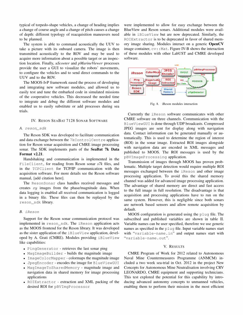
5) 2D Topview Display: The 2D Topview Display (Fig. 4)shows a top view of the working zone and includes featureslike auto zoom, nav info display, floating heading indicators,visualisation of way points, real-time visualisation of sensors
(a) Surface-tow mode (b) Surface-thrusted mode
(c) ROV operation mode (d) ROV with submerged tow line in
Fig. 2. Operation Modes
Fig. 3. Advanced Pilot Interface
measurements (INS, DVL, USBL, GPS, etc.), distance & anglemeasurements tools, ROV-fixed, SHIP-fixed and free LeverArms etc.
6) 3D Real-Time Augmented Reality Display: The 3D Real-Time Augmented Reality Display (Fig. 5) provides 3D real-time visualisation of the support vessel, ROV, ocean energydevice, ocean surface, seabed, etc.
B. Reson SeaBat 7128 Sonar
In addition, as a payload sensor, Latis hosts a multibeamsonar, the Reson SeaBat 7128, which was for this experimentconfigured as a forward-looking sonar (FLS). This version ofSeaBat 7128 operates at 400 kHz and illuminates a 128 ◦ hori-zontal sector. This system can be used either as a standalone orin conjunction with a permanently installed system for which it
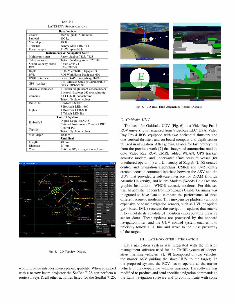
TABLE ILATIS ROV SPECIFICATIONS
Base VehicleChassis Marine grade AluminiumPayload 100 kgMax. depth 1000 mThrusters Seaeye SM4 (4H, 4V)Power supply 11kW, upgradable
Instruments & Navigation SuiteMultibeam sonar Reson SeaBat 7125, 7128Sidescan sonar Tritech SeaKing sonar 325 kHzSound velocity probe Reson SVP-24INS ixSea PHINSDepth CDL Microbath (Digiquartz)DVL RDI WorkHorse Navigator 600USBL interface iXsea GAPS, Kongsberg HiPAP
GPS (surface) CSI-Wireless Seres or SubmersibleGPS GPRS-6015G
Obstacle avoidance 6 Tritech single-beam echosounders
CamerasBowtech Explorer-3K monochrome2 LCC-600 monochromeTritech Typhoon colour
Pan & tilt Bowtech SS-109
Lights3 Bowtech LED-16001 Bowtech LED-8002 Tritech LED lite
Control System
Embedded Digital Logic EBX945National Instruments Compact RIO
Topside Control PCTritech Typhoon colour
Max. depth 1000 mUmbilical
Length 400 mDiametar 25 mmCore 6 AC, 4 DC, 8 single mode fibres
Fig. 4. 2D Topview Display
would provide intruder interception capability. When equippedwith a narrow beam projector the SeaBat 7128 can perform aroute surveys & all other activities listed for the SeaBat 7125.
Fig. 5. 3D Real-Time Augmented Reality Displays
C. Goldrake UUV
The basis for Goldrake UUV, (Fig. 6), is a VideoRay Pro 4ROV university kit acquired from VideoRay LLC, USA. VideoRay Pro 4 ROV equipped with two horizontal thrusters andone vertical thruster, and on-board compass and depth sensorutilized in navigation. After getting an idea for fast prototypingfrom the previous work [7] that integrated automarine moduleonto Video Ray ROV, CMRE added WLAN, GPS tracker,acoustic modem, and underwater aBox pressure vessel (foruntethered operation) and University of Zagreb (UoZ) createdcontrol and navigation algorithms. CMRE and UoZ jointlycreated acoustic command interface between the ASV and theUUV that provided a software interface for DPAM (FloridaAtlantic University) and Micro Modem (Woods Hole Oceano-graphic Institution - WHOI) acoustic modems. For this seatrial an acoustic modem from EvoLogics GmbH, Germany wasintegrated to have data to compare the performance of threedifferent acoustic modems. This inexpensive platform (withoutexpensive onboard navigation sensors, such as DVL or opticalgyro-based IMU) receives the navigation updates that enableit to calculate its absolute 3D position (incorporating pressuresensor data). These updates are processed by the onboardnavigation filter, and the UUV control system enables it toprecisely follow a 3D line and arrive to the close proximityof the target.
III. LATIS-SCOOTER INTEGRATION
Latis navigation system was integrated with the missionmanagement software used for the CMRE system of cooper-ative maritime vehicles [8], [9] (composed of two vehicles,the master ASV guiding the slave UUV to the target). Inthe proposed system, the ROV has to operate as the mastervehicle in the cooperative vehicles missions. The software wasmodified to produce and send specific navigation commands tothe Latis navigation software and to communicate with some

Fig. 6. Goldrake aROV
hardware modules (FLMS and an acoustic modem) positionedonboard the ROV. We added also the possibility to integrateand use onboard Latis different typologies of sonar andacoustic modems. Different devices have been tested duringour at-sea trials to evaluate their performance in differentscenarios (e.g. shallow and deep waters, acoustically noisyenvironments, etc.) to select the most suited to the missionrequirements. Specifically, the devices that could be mountedon the ROV were:
• Forward looking multi-beam sonar: Reson SDK or Blue-view P450.
• Acoustic modem: Evologics modem or WHOI Micro-Modem.
The mission management software is executed on a PClocated on the support vessel (called Scooter-PC). A LANconnects the Scooter-PC to the Latis Navigation PC (alsolocated on the support vessel and executing the ROV guidancealgorithms in LabVIEW ©NI environment) and to the FLMSand the modem located on the ROV. Latis Navigation PCthen communicates through the umbilical cable with the ROVonboard controller computers controlling the revolution speedsof the vehicle’s 8 thrusters.
The architecture of the software running on Scooter-PC isbased on MOOS-IvP [10]. MOOS-IvP is an open source C++framework for providing autonomy to robotic platforms, inparticular marine vehicles. MOOS-IvP is based on the mailboxparadigm: a community of processes subscribe to receive andpublish variables from/to a database (MOOSDB). For themanagement and control of vehicles, the MOOS frameworkworks according to the backseat-driver paradigm: a backseatcomputer executes the processes managing the mission andproduces commands for a frontseat computer in charge of thevehicle low-level control [10].
In Fig. 7 a scheme of the main processes of our system isshown. pScooter is the process managing the ROV missionand producing the data/commands to the UUV. It reads thenavigation data (latitude, longitude, depth, heading and pitchangles, etc.) coming from ROV Latis and the range/bearingof the UUV produced by the image processing module fromsonar images. Then, pScooter estimates the position of theUUV and produces localization data and, on the basis of thecurrent operative state, generates commands for the UUV andnavigation commands for the Latis navigation software. Thedata directed to the UUV are then read and transmitted to theacoustic modem by dedicated processes (e.g. pCommToUV,pNemoQueue). To communicate with the Latis navigationalgorithms, the process pBridgeMOOS_Latis is used. Thisprocess communicates with the Latis navigation software byusing the LabVIEW shared variables mechanism. pBridge-MOOS_Latis makes available to pScooter all the variablesregarding the status and pose of the ROV by publishing them tothe MOOSDB. On the other side, it reads from the MOOSDBthe produced navigation commands and makes them availableto the LATIS navigation algorithms for their execution. Twopossibile strategies were considered and implemented concern-ing the movement commands for the ROV produced by themission management system:
• Latis control mode - pScooter computes the objectiveROV 3D location along with the desired vehicle’s pitchand heading. These data are sent to the Latis navigationalgorithms that execute the received commands. In thisstrategy the holonomy of the ROV is fully exploitedenabling the execution of movements with course anglediffering from heading angle.
• Helm control mode - pHelmIvP process receives thedesired Latis 3D position created by pScooter and pro-duces the appropriate depth, heading and surge speedreferences. The commands produced by pHelmIvP arecoherent with considering the ROV a non-holonomicvehicle like all the torpedo-shape AUVs generally are.
The two strategies have been tested in the trials. We usedboth to investigate the behavior and the performance of thesystem of cooperative vehicles in the two different cases: withthe use of non-holonomic navigation for ROV we investigatedthe possibility to export the developed navigation concept alsoto torpedo-shape AUVs (e.g. REMUS AUV).
The two strategies can impact especially on ROV reac-quisition behaviors design [11]. Reacquisition behaviors arespecific movements of the master vehicle triggered when theUUV is “lost” by the tracking algorithm. This may happeneither in case of the UUV exiting the sonar FOV, or in case ofsome errors/failures in the automatic image processing. Somepurposely designed maneuvers of the master vehicle can infact increase the odds the UUV is detected again. With theholonomic navigation, we can plan maneuvers in which acertain course is kept and the vehicle heading and pitch anglesare modified to explore the search area with the sonar toredetect the UUV. Otherwise in the non-holonomic navigation
typical of torpedo-shape vehicles, a change of heading impliesa change of course angle and a change of pitch causes a changeof depth: different typology of reacquisition maneuvers needto be planned.
The system is able to command acoustically the UUV totake a picture with its onboard camera. The image is thentransmitted acoustically to the ROV and may be used toacquire more information about a possible target or an inspec-tion location. Finally, uScooter and pMarineViewer processesprovide the user a GUI to visualize the robots’ movements,to configure the vehicles and to send direct commands to theUUV and to the ROV.
The MOOS-IvP framework eased the process of developingand integrating new software modules, and allowed us toeasily test and tune the embarked code in simulated missionsof the cooperative vehicles. This decreased the needed timeto integrate and debug the different software modules andenabled us to easily substitute or add processes during seatrials.
IV. RESON SEABAT 7128 SONAR SOFTWARE
A. reson_sdk
The Reson SDK was developed to facilitate communicationand data exchange between the 7kControlCentre applica-tion for Reson sonar acquisition and CMRE image processingsonar. The SDK implements parts of the SeaBat 7k DataFormat v2.21.
Handshaking and communication is implemented in theFileClient, for reading from Reson sonar s7k files, andin the TCPClient for TCP/IP communication with theacquisition software. For more details see the Reson softwaremanual, [add citation here].
The ResonSonar class handles received messages andcreates xy images from the phase/magnitude data. Whendata logging is enabled all received communication is loggedin a binary file. These files can then be replayed by thereson_sdk library.
B. iReson
Support for the Reson sonar communication protocol wasimplemented in reson_sdk. The iReson application actsas the MOOS frontend for the Reson library. It was developedas the sister application of the iBlueView application, devel-oped by A. Grati (CMRE). Modules providing iBlueViewlike capabilities:
• PingGenerator - retrieves the last sonar ping• MagImageBuilder - builds the magnitude image• ImageColorMapper - colormaps the magnitude image• JpegEncoder - encodes the image for BlueViewGUI• MagImageToSharedMemory - magnitude image and
navigation data in shared memory for image processingapplications
• ROIExtractor - extraction and XML packing of thedesired ROI for pBVImgProcessor
were implemented to allow for easy exchange between theBlueView and Reson sonars. Additional modules were avail-able in iBlueView but are now deprecated. Similarly, theROIExtractor is to be deprecated in favor of shared mem-ory image sharing. Modules interact on a generic OpenCVimage container, cv::Mat. Figure IV-B shows the interactionof these modules with other LabUST and CMRE developedsoftware.
Fig. 8. iReson modules interaction
Currently the iReson software communicates with otherCMRE software on three channels. Communication with theBlueViewGUI is done through UDP broadcasts. CompressedJPEG images are sent for display along with navigationdata. Contact information can be generated manually or au-tomatically. This is used to determine the region of interest(ROI) in the sonar image. Extracted ROI images alongsidewith navigation data are encoded in XML messages andpublished to MOOS. The ROI messages is used by thepBVImageProcessing application.
Transmission of images through MOOS has proven prob-lematic. Multiple target detection would require multiple ROImessages exchanged between the iReson and other imageprocessing application. To avoid this the shared memorychannel was added for advanced image processing application.The advantage of shared memory are direct and fast accessto the full image in full resolution. The disadvantage is thatacquisition and processing applications have to run on thesame system. However, this is negligible since both sonarsare network based sensors and allow remote acquisition bydefault.
MOOS configuration is generated using the plug file. Thesubscribed and published variables are shown in table II.Variable names can be user specified, therefore we use genericnames as specified in the plug file. Input variable names startwith “variable-name.in” and output names start with“variable-name.out”.
V. RESULTS
CMRE Program of Work for 2012 related to AutonomousNaval Mine Countermeasures Programme (ANMCM) in-cluded a two week sea-trial in Oct. 2012 in the project NewConcepts for Autonomous Mine Neutralisation involving CRVLEONARDO, CMRE equipment and supporting technicians.This test explored the potential for this capability by intro-ducing advanced autonomy concepts to unmanned vehicles,enabling them to perform their mission in the most efficient
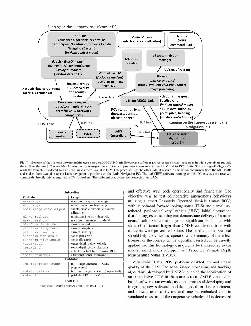
Fig. 7. Scheme of the system software architecture based on MOOS-IvP middleware(the different processes are shown - processes in white containers providethe GUI to the user). Scooter MOOS community manages the mission and produces commands to the UUV and to ROV Latis. The pBridgeMOOS_LATISreads the variables produced by Latis and makes them available to MOOS processes. On the other side, it reads the navigation commands from the MOOSDBand makes them available to the Latis navigation algorithms on the Latis Navigation PC. The LabVIEW software running on this PC executes the receivedcommands directly interacting with ROV controllers. The different computers are connected via LAN.
SubscribesVariable Usagemax-range maximum acquisition rangemin-range minimum acquisition rangebool-image-auto-adjust enable/disable automatic contrast
adjustmentmin-threshold minimum intensity thresholdmax-threshold maximum intensity thresholdplatfrom-latitude current latitudeplatform-longitude current longitudeplatform-heading current headingplatform-pan-angle sonar pan angleplatform-tilt-angle sonar tilt anglewater-depth water depth below vehiclehead-depth sonar depth below platformcontact vehicle contact to determine ROIsonar-commands additional sonar commands
Publishesxml-magnitude-image full image encoded in XML
(deprecated)xml-jpeg-image full jpeg image in XML (deprecated)xml-roi published ROI in XML
TABLE IIIRESON SUBSCRIPTIONS AND PUBLICATIONS
and effective way, both operationally and financially. Theobjective was to test collaborative autonomous behavioursutilizing a smart Remotely Operated Vehicle (smart ROV)with its onboard forward looking sonar (FLS) and a small un-tethered “payload delivery” vehicle (UUV). Initial discussionsthat the suggested teaming can demonstrate delivery of a mineneutralisation vehicle to targets at significant depths and withstand-off distances longer than CMRE can demonstrate withits assets were proven to be true. The results of this sea trialshould help convince the operational community of the effec-tiveness of the concept as the algorithms tested can be directlyapplied and this technology can quickly be transitioned to themodern minehunters equipped with Propelled Variable DepthMinehunting Sonar (PVDS).
Very stable Latis ROV platform enabled optimal imagequality of the FLS. The sonar image processing and trackingalgorithms, developed by UNIZG, enabled the localization ofan inexpensive UUV in the sonar screen. CMRE’s behavior-based software framework eased the process of developing andintegrating new software modules needed for this experiment,and allowed us to easily test and tune the embarked code insimulated missions of the cooperative vehicles. This decreased

the needed time to integrate and debug the different softwaremodules and enabled us to easily substitute or add processesduring sea trials. Latis ROV tracked the UUV via the sonaracoustically sending position fixes to it (Latis position, rangeand bearing to the UUV) and followed the UUV during itsdescent with a stand-off distance, as shown in (Fig. 10(a)).
A. Sonar Imagery and Control performance of dual underwa-ter robot system
The concept of external system guidance being investigatedwas tested with Latis ROV re-acquiring a bottom targetusing a high-resolution forward-looking imaging sonar, andguiding the delivery vehicle to the target with minimal controlinformation sent via simplified acoustic modem.
The control system of Latis ROV includes fast auto-tuningof low-level controllers, automatic thruster fault detection andaccommodation, semi-automatic and fully-automatic controlmodes, optimal control allocation of thrusters, etc. The auto-tuning process of Heave (Depth) and Yaw low-level controllersinvolves the following steps: (1) Generate self-oscillations; (2)Wait for transient stage to finish; (3) Measure amplitude andperiod of steady-state oscillations; and (4) Find new valuesof controller gains using tuning rules. A novel set of tuningrules for underwater applications has been developed, whichprovides the optimal performance of low-level controllersin the case of configuration changes and the presence ofdisturbances (waves & sea currents).
Once Latis ROV spots the target within the onboard multi-beam sonar image, the coordinates of the target in the Earthframe are recorded (using onboard altimeters and pressuresensors the depth of the target can be obtained). As shown in(Fig. 9(a)), the cylindrical type target needs to be distinguishedfrom bottom clutter (a rock purposely placed for the sea trialnext to it) and the Automatic Target Recognition algorithms,described in [12], can be used for this purpose. The coordinatesof the target are sent to the UUV via an acoustic link.
Once the target location is known, multibeam sonar thatis mounted on the Latis ROV acquires the UUV (might belong distance away from the target) highlight in the sonarimage, (Fig. 9(b)). Since the multibeam sonar is a 2D sensorit will detect the slant range and bearing of the echo. Thesonar processing algorithm with choose a 2D position estimatebetween clutter echoes and the UUV echo. To calculate the 3Dposition the UUV depth has to be know, however, due to theone sided communication the depth is unknown. Therefore,it is necessary to send the measured sonar slant-range andabsolute bearing to the UUV. Via an acoustic link Latis ROVsends its x and y coordinates, slant-range, and the absolutebearing at a rate of 0.5 Hz, depending on the quality ofthe acoustic modem link. This is the minimum (40 bits)information that needs to be send to the UUV as its navigationupdate.
Combining the positional navigation update and depth mea-sured onboard, the UUV can calculate its position in 3D.UUV draws a line between itself and the target. Then, the3D line following problem can be observed as following two
(a) Cylindrical type target and a rock
(b) Goldrake on the way to 80m target
Fig. 9. Targets on 80 m depth and Goldrake in the water column
lines simultaneously: horizontal and vertical line. Models ofthe lines can be derived and the line-following controllerscan be used to minimize the distance to the horizontal line(using the updates about the horizontal position arriving viaaccoustic modem) and to the vertical line (measuring depthwith the pressure sensor). When the initialization procedureis completed (target location passed to the UUV), line fol-lowing algorithm is engaged. The line following controllersimplemented onboard of the UUV are explained in [5].
Latis and Goldrake 3D trajectories during one trial areshowed in (Fig. 10(a)). A close look at Goldrake performancecan been seen in (Fig. 10(b)).
Goldrake was acoustically commanded by Latis to descendat 52 m. During the descent Latis kept a stand-off distance (25m) from the UUV. Latis maneuvered to keep the UUV intothe sonar field-of-view. When Goldrake arrived at 52 m, theline-following command was issued. Then, the UUV startedmoving following a 3D line joining its current position to thetarget. During the movement, Latis followed the UUV trackingthat with the sonar and acoustically sending position fix. Themission was successfully accomplished. Detailed data aboutthe line following are showed in Fig. 10(b) where the verticalerror dV and horizontal error dH with respect to the line to befollowed (vertical and horizontal projections) are visible. Theerrors remain limited showing the Goldrake is following thedesired line to the target.
The key features of this approach are:

(a) Latis (blue) and Goldrake (red) 3D position
(b) Goldrake performance
Fig. 10. Latis ROV and Goldrake joint mission to the target at 80 m depth
1) This approach utilizes one way communication betweenthe Latis ROV and UUV (top to down). Any otherapproach would require UUV sending its depth to theLatis ROV.
2) The Kalman filtering onboard of the UUV enables thenavigation in the cases when measurements are notavailable.
3) The multibeam sonar mounted on the Latis ROV neednot have the target and the UUV in the field of view atall times, but only the UUV. If the target is in the fieldof view, corrected target position can optionally be sentto the UUV. This is useful in case of the positional driftof the ROV.
4) If the ROV drifts due to winds, waves, or currents, theUUV will not drift with it but it will stay on the linewhich has been determined initially.
B. Blueview P900 vs. Reson 7128 Sonar
The high-resolution, multibeam imaging sonar available atCMRE and previously used for this project was the BlueViewP900, operating at 900 kHz. Prior experimentation has shownthat although other sonars might provide more detailed im-agery, the BlueView P900 represents a good balance of size(important for drag considerations), cost, and performance.Objects on the order of 2 m in length can be spotted in thedisplay out to a maximum range of approximately 35 m andbe readily classified at ranges of nearly 20 m.
The trials described in this paper allowed us to comparethe performance of the two forward looking sonars: Reson’sSeaBat 7128 and Blueview’s P900. Both of these can be con-sidered as "guiding" sonars on an autonomous either surfaceor underwater vehicle in future. All subfigures in Fig. 11contain three targets: 1) A rock at ∼ 10m from the sonarhead, 2) Goldrake UUV, at ∼ 20-23 m from the sonar head,and 3) cylinder surrogate target, initially at ∼ 30 m from thesonar head (to the left). The (Fig. 11(a)), (Fig. 11(b)), and(Fig. 11(c)) show the images of the movement of the UUVwhich reaches the cylinder target in (Fig. 11(c)). From allthe figures in (Fig. 11) it can be seen that the resolution of7128 sonar is better than that of P900. The higher resolutionwould contribute to the performance of the Automatic TargetRecognition algorithms, described in [12], as it is clear fromthe imagery that there exist a distinct shadow of the cylindricaltarget in case of Reson sonar and this is not always the casefor Blueview sonar. Moreover, our automatic target trackingalgorithm never lost the track of Goldrake UUV when Resonsonar was used which sometimes occurs when Blueview sonaris used for tracking and guiding.
Additional objectives of the trial, not discussed in this paper,were to send the image of the target via accoustic communi-cation link from the UUV and to perform the guiding overlonger distances (beyond the range of the above mentionedsonars) via the ship based ultra short baseline (USBL) acousticpositioning system. The first investigates the potential useof the camera (which comes as a standard sensor on thecommercial ROV being used for testing) for providing opticalidentification information on the mine target as the UUV lands,while the second investigates the potential of guiding multipleunderwater robots by a capable robot over extended distances.
VI. CONCLUSION
The use of autonomous systems has the potential to trans-form existing MCM capabilities in NATO from a Cold Warlegacy focused on time consuming clearance with surfaceships, to a quickly deployable (air/sea lift), scalable systemwhich offers an order of magnitude increase in speed of opera-tion, reduction in life-cycle cost and increased interoperabilityover existing systems. The use of autonomous systems forMCM also reduces risk to personnel and expensive materiel,i.e., one goal is to “get the man out of the minefield.” Thistransformation is under way today as seabed surveys formine detection are now routinely conducted with autonomous

(a) Three targets at: 10m, 20 m (both center), and 30 m (left)
(b) Goldrake (middle of the screen) moving toward the cylinder
(c) Goldrake finishing its mission, reaching the cylinder
Fig. 11. Reson 7128 versus Blueview P900
underwater vehicles (AUVs), resulting in an exponential in-crease in search speed capability. The introduction of oneshot weaponised AUV type vehicles has also hugely reducedthe traditionally time consuming neutralisation part of theMCM process. However, neutralisation efforts are still operatorintensive, and require the vehicles to be tethered to a commandship for control purposes.
In the sea trial the smart ROV Latis from the Universityof Limerick (UL) was used as a guiding platform and anautomated Video Ray Pro 4 ROV was used as an inexpen-sive UUV - could be considered as one shot weaponisedAUV type vehicle. This method enables precise navigationof multiple inexpensive UUVs in a coordinated fashion in 3D
space, without costly on-board 3D, 6 DOF pose estimationsensors (eg., optical gyro-based IMUs), velocity estimationDoppler velocity logs (DVL), or deployed underwater acousticpositioning systems (Long baseline – LBL or Ultra ShortBaseline - USBL). The 3D navigation accuracy of 20 cm inthe horizontal and 10 cm in the vertical plane was achieved forthe path length of hundreds of meters. This accuracy assuresthe precise underwater navigation required by most of theapplications of the underwater robots. The collaboration withthe Mobile & Marine Robotics Research Centre at Universityof Limerick raised our project’s output to the next level sincewe, not only demonstrated the external guiding concept in3D, but also in environmental conditions equivalent to theconditions of current mine disposal operations.
ACKNOWLEDGEMENTS
The authors want to thank Alberto Grati and Stefano Fiora-vanti for their invaluable engineering support and the CMREETD staff for their helpfulness during ANT12 trials. We arealso very thankful John Fraser and Richard Fotheringham fromRESON Offshore Ltd. for their help prior and during the seatrial and providing the sonar projector at no cost.
REFERENCES
[1] P. Miller, J. Farrell, Y. Zhao, and V. Djapic, “Autonomous underwatervehicle navigation,” IEEE Journal of Oceanic Engineering, vol. vol.35(3), pp. 663–678, 2010.
[2] F. Baralli, B. Evans, E. Coiras, and A. Bellettini, “AUV navigation forMCM operations,” NATO Undersea Research Centre, La Spezia, Italy,Technical report, 2007.
[3] J. C. Kinsey, R. M. Eustice, and L. L. Whitcomb, “A survey ofunderwater vehicle navigation: recent advances and new challenges,”in Proc. of MCMC, Lisbon, 2006.
[4] A. Alcocer, P. Oliveira, and A. Pascoal, “Study and implementation of anekf gib-based underwater positioning system,” in IFAC CAMS04, 2004.
[5] D. N. N. Miskovic, V. Djapic and Z. Vukic, “Multibeam sonar-basednavigation of small uuvs for mcm purposes,” in Proceedings of the 18thIFAC World Congress, Milano ( Italy), 2011.
[6] J. R. D. Toal, E. Omerdic and S. Nolan, “Multi-mode operations marinerobotics vehicle - mechatronics case study,” Ch. 7 in Mechatronics inAction: Case Studies in Mechatronics - Applications and Education, vol.ISBN 978-1-84996-079-3, Springer-Verlag London, 2010.
[7] M. Stipanov, N. Miskovic, Z. Vukic, and M. Barisic, “ROV autonomiza-tion – yaw identification and Automarine module architecture,” Proc. ofthe CAMS’07 Conference, 2007.
[8] V. Djapic and D. Nad, “Collaborative autonomous vehicle use in minecountermeasures,” Sea Technology Magazine, Nov. 2010.
[9] G. Ferri, A. Manzi, F. Fornai, B. Mazzolai, C. Laschi, F. Ciuchi,and P. Dario, “Design, fabrication and first sea trials of a small-sizedautonomous catamaran for heavy metals monitoring in coastal waters,”in Proc. of ICRA 2011, Shanghai, China, 2011.
[10] http://oceanai.mit.edu/moos-ivp/pmwiki/pmwiki.php., Std.[11] G. Ferri and V. Djapic, “Adaptive mission planning for cooperative
autonomous maritime vehicles,” in to appear in Proc. of ICRA 2013,Karlsruhe, Germany, 2013.
[12] E. Galceran, V. Djapic, M. Carreras, and D. P. Williams, “A real-timeunderwater object detection algorithm for multi-beam forward lookingsonar,” in 3rd IFAC Workshop on Navigation, Guidance and Control ofUnderwater Vehicles, Porto, Portugal, 2012.


![A Navigation System For Underwater Vehicles Integrating DVL [Αυτόματη αποθήκευση]](https://img.pdfslide.net/doc/110x75/5881db081a28ab331a8b766d/a-navigation-system-for-underwater-vehicles-integrating-dvl-.jpg)
