Embed Size (px)
Citation preview
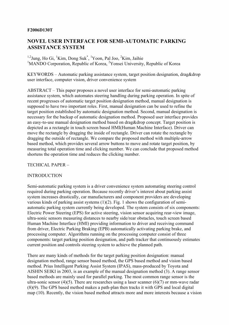
F2006D130T NOVEL USER INTERFACE FOR SEMI-AUTOMATIC PARKING ASSISTANCE SYSTEM 1,2Jung, Ho Gi, 1Kim, Dong Suk*, 1Yoon, Pal Joo, 2Kim, Jaihie 1MANDO Corporation, Republic of Korea, 2Yonsei University, Republic of Korea KEYWORDS – Automatic parking assistance system, target position designation, drag&drop user interface, computer vision, driver convenience system ABSTRACT – This paper proposes a novel user interface for semi-automatic parking assistance system, which automates steering handling during parking operation. In spite of recent progresses of automatic target position designation method, manual designation is supposed to have two important roles. First, manual designation can be used to refine the target position established by automatic designation method. Second, manual designation is necessary for the backup of automatic designation method. Proposed user interface provides an easy-to-use manual designation method based on drag&drop concept. Target position is depicted as a rectangle in touch screen based HMI(Human Machine Interface). Driver can move the rectangle by dragging the inside of rectangle. Driver can rotate the rectangle by dragging the outside of rectangle. We compare the proposed method with multiple-arrow based method, which provides several arrow buttons to move and rotate target position, by measuring total operation time and clicking number. We can conclude that proposed method shortens the operation time and reduces the clicking number. TECHICAL PAPER – INTRODUCTION Semi-automatic parking system is a driver convenience system automating steering control required during parking operation. Because recently driver’s interest about parking assist system increases drastically, car manufacturers and component providers are developing various kinds of parking assist systems (1)(2). Fig. 1 shows the configuration of semi-automatic parking system currently being developed. The system consists of six components: Electric Power Steering (EPS) for active steering, vision sensor acquiring rear-view image, ultra-sonic sensors measuring distances to nearby side/rear obstacles, touch screen based Human Machine Interface (HMI) providing information to driver and receiving command from driver, Electric Parking Braking (EPB) automatically activating parking brake, and processing computer. Algorithms running on the processing computer consist of three components: target parking position designation, and path tracker that continuously estimates current position and controls steering system to achieve the planned path. There are many kinds of methods for the target parking position designation: manual designation method, range sensor based method, the GPS based method and vision based method. Prius Intelligent Parking Assist System (IPAS), mass-produced by Toyota and AISHIN SEIKI in 2003, is an example of the manual designation method (3). A range sensor based methods are mainly used for parallel parking. The most common range sensor is the ultra-sonic sensor (4)(5). There are researches using a laser scanner (6)(7) or mm-wave radar (8)(9). The GPS based method makes a path-plan then tracks it with GPS and local digital map (10). Recently, the vision based method attracts more and more interests because a vision
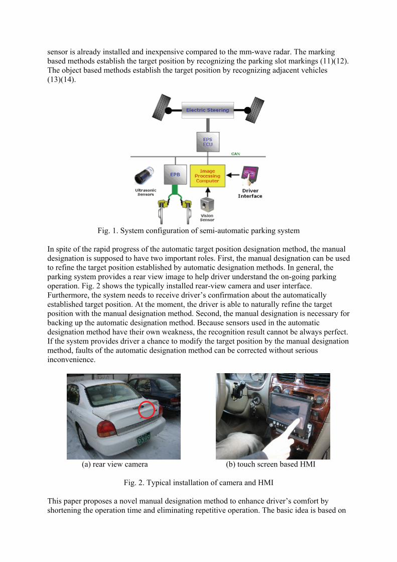
sensor is already installed and inexpensive compared to the mm-wave radar. The marking based methods establish the target position by recognizing the parking slot markings (11)(12). The object based methods establish the target position by recognizing adjacent vehicles (13)(14).
Fig. 1. System configuration of semi-automatic parking system
In spite of the rapid progress of the automatic target position designation method, the manual designation is supposed to have two important roles. First, the manual designation can be used to refine the target position established by automatic designation methods. In general, the parking system provides a rear view image to help driver understand the on-going parking operation. Fig. 2 shows the typically installed rear-view camera and user interface. Furthermore, the system needs to receive driver’s confirmation about the automatically established target position. At the moment, the driver is able to naturally refine the target position with the manual designation method. Second, the manual designation is necessary for backing up the automatic designation method. Because sensors used in the automatic designation method have their own weakness, the recognition result cannot be always perfect. If the system provides driver a chance to modify the target position by the manual designation method, faults of the automatic designation method can be corrected without serious inconvenience.
(a) rear view camera (b) touch screen based HMI
Fig. 2. Typical installation of camera and HMI
This paper proposes a novel manual designation method to enhance driver’s comfort by shortening the operation time and eliminating repetitive operation. The basic idea is based on
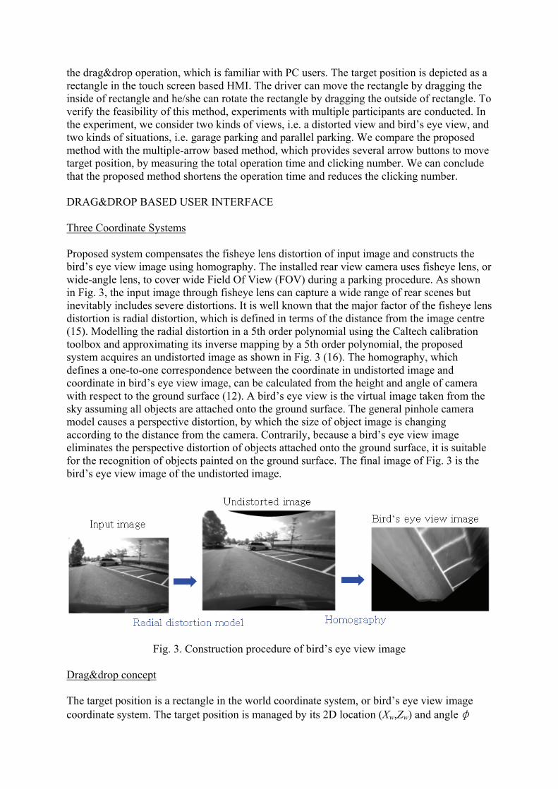
the drag&drop operation, which is familiar with PC users. The target position is depicted as a rectangle in the touch screen based HMI. The driver can move the rectangle by dragging the inside of rectangle and he/she can rotate the rectangle by dragging the outside of rectangle. To verify the feasibility of this method, experiments with multiple participants are conducted. In the experiment, we consider two kinds of views, i.e. a distorted view and bird’s eye view, and two kinds of situations, i.e. garage parking and parallel parking. We compare the proposed method with the multiple-arrow based method, which provides several arrow buttons to move target position, by measuring the total operation time and clicking number. We can conclude that the proposed method shortens the operation time and reduces the clicking number. DRAG&DROP BASED USER INTERFACE Three Coordinate Systems Proposed system compensates the fisheye lens distortion of input image and constructs the bird’s eye view image using homography. The installed rear view camera uses fisheye lens, or wide-angle lens, to cover wide Field Of View (FOV) during a parking procedure. As shown in Fig. 3, the input image through fisheye lens can capture a wide range of rear scenes but inevitably includes severe distortions. It is well known that the major factor of the fisheye lens distortion is radial distortion, which is defined in terms of the distance from the image centre (15). Modelling the radial distortion in a 5th order polynomial using the Caltech calibration toolbox and approximating its inverse mapping by a 5th order polynomial, the proposed system acquires an undistorted image as shown in Fig. 3 (16). The homography, which defines a one-to-one correspondence between the coordinate in undistorted image and coordinate in bird’s eye view image, can be calculated from the height and angle of camera with respect to the ground surface (12). A bird’s eye view is the virtual image taken from the sky assuming all objects are attached onto the ground surface. The general pinhole camera model causes a perspective distortion, by which the size of object image is changing according to the distance from the camera. Contrarily, because a bird’s eye view image eliminates the perspective distortion of objects attached onto the ground surface, it is suitable for the recognition of objects painted on the ground surface. The final image of Fig. 3 is the bird’s eye view image of the undistorted image.
Fig. 3. Construction procedure of bird’s eye view image Drag&drop concept The target position is a rectangle in the world coordinate system, or bird’s eye view image coordinate system. The target position is managed by its 2D location (Xw,Zw) and angle φ

with respect to Xw-axis. The width and length of target position rectangle are determined based on the ego-vehicle’s width and length. With the radial distortion model and homography, a point in the bird’s eye view image coordinate system is corresponding to a point in distorted image coordinate system or input image coordinate system. Therefore, by converting every coordinates into bird’s eye view image coordinate system, we can implement any kinds of operations in one coordinate system uniformly. The target position rectangle and user input are treated in the bird’s eye view image coordinate system, and then are converted to the proper coordinate system according to the display mode. The target position rectangle displayed in the touch screen based HMI acts as a cursor while the driver is establishing the target position. The inside region of rectangular target position is used as a moving cursor. The driver can move the location of target position by dragging the inside as shown in Fig. 4(a). The outside region of rectangular target position is used as a rotating cursor. The driver can rotate the target position, or change the angle, by dragging the outside as shown in Fig. 4(b). Three kinds of operations are needed: 1) method determining whether a driver’s input, i.e. pointing point, is in the target position rectangle or not, 2) with the driver’s two consecutive inputs, calculation of translation transformation, and 3) with driver’s two consecutive inputs, calculation of rotation transformation.
(a) Moving by dragging the inside of rectangle
(b) Rotating by dragging the outside of rectangle
Fig. 4. Target position rectangle as moving and rotating cursor
Mode Selection

Whether a point is in a rectangle or not can be determined by checking if the point is at the same side of four rectangle-sides in the rotating direction. In this application, the relative location between four corner points cannot be determined because the rectangle can be rotated. Only the order between four corner points is confirmed. C1, C2, C3, C4 are four corner points of a rectangle in the rotating direction and T is the user pointing point. We can define a cross-product between two vectors, e.g. C1C2 and C1T as depicted in Fig. 5. If all z-components of four cross-products have the same sign, then we can confirm that the point T is located in the rectangle as shown in Fig. 6(a). Contrarily, if any z-components of four cross-products has a different sign, then we can confirm that the point T is located out of the rectangle as shown in Fig. 6(b).
Fig. 5. Cross-product between a rectangle-side and corner-pointing
(a) Four cross-product have the same direction (b) One cross-product has different direction
Fig. 6. Determining whether a point is in a rectangle or not
Translation of Target Position A translation transformation is equally applied to every points of target rectangle. Therefore, a new target position can be determined by adding the difference vector between two consecutive user input points, P1, P2 , to the current target position as shown in Fig. 7(a). Rotation of Target Position A rotation transformation with respect to the centre point C is equally applied to every points of the target rectangle. Therefore, a new target position can be determined by rotating the current target position with respect to C by the between-angle θ of two consecutive user input points as shown in Fig. 7(b).
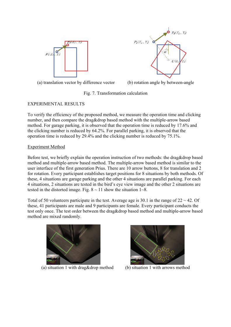
(a) translation vector by difference vector (b) rotation angle by between-angle
Fig. 7. Transformation calculation
EXPERIMENTAL RESULTS To verify the efficiency of the proposed method, we measure the operation time and clicking number, and then compare the drag&drop based method with the multiple-arrow based method. For garage parking, it is observed that the operation time is reduced by 17.6% and the clicking number is reduced by 64.2%. For parallel parking, it is observed that the operation time is reduced by 29.4% and the clicking number is reduced by 75.1%. Experiment Method Before test, we briefly explain the operation instruction of two methods: the drag&drop based method and multiple-arrow based method. The multiple-arrow based method is similar to the user interface of the first generation Prius. There are 10 arrow buttons, 8 for translation and 2 for rotation. Every participant establishes target positions for 8 situations by both methods. Of these, 4 situations are garage parking and the other 4 situations are parallel parking. For each 4 situations, 2 situations are tested in the bird’s eye view image and the other 2 situations are tested in the distorted image. Fig. 8 ~ 11 show the situation 1~8. Total of 50 volunteers participate in the test. Average age is 30.1 in the range of 22 ~ 42. Of these, 41 participants are male and 9 participants are female. Every participant conducts the test only once. The test order between the drag&drop based method and multiple-arrow based method are mixed randomly.
(a) situation 1 with drag&drop method (b) situation 1 with arrows method
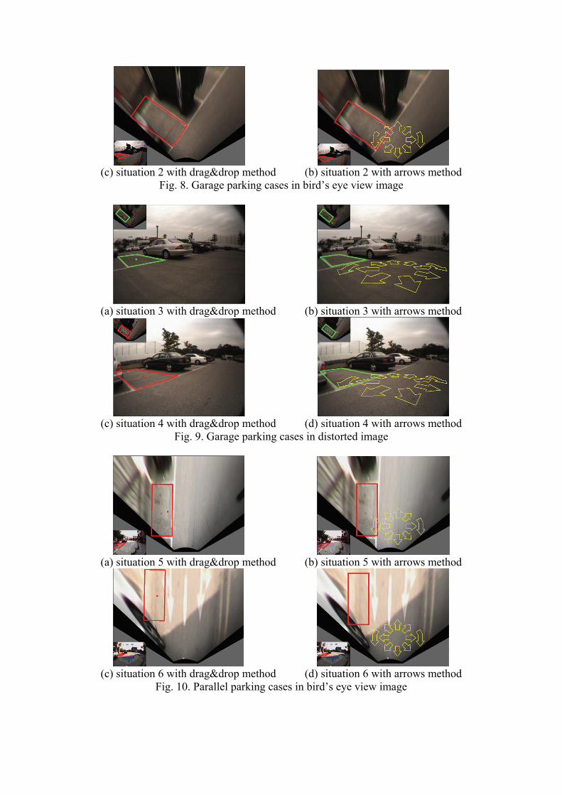
(c) situation 2 with drag&drop method (b) situation 2 with arrows method
Fig. 8. Garage parking cases in bird’s eye view image
(a) situation 3 with drag&drop method (b) situation 3 with arrows method
(c) situation 4 with drag&drop method (d) situation 4 with arrows method
Fig. 9. Garage parking cases in distorted image
(a) situation 5 with drag&drop method (b) situation 5 with arrows method
(c) situation 6 with drag&drop method (d) situation 6 with arrows method
Fig. 10. Parallel parking cases in bird’s eye view image
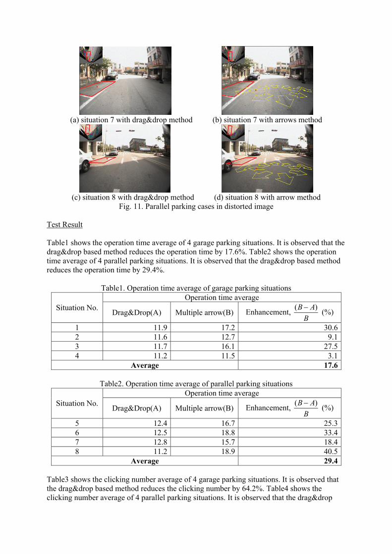
(a) situation 7 with drag&drop method (b) situation 7 with arrows method
(c) situation 8 with drag&drop method (d) situation 8 with arrow method
Fig. 11. Parallel parking cases in distorted image Test Result Table1 shows the operation time average of 4 garage parking situations. It is observed that the drag&drop based method reduces the operation time by 17.6%. Table2 shows the operation time average of 4 parallel parking situations. It is observed that the drag&drop based method reduces the operation time by 29.4%.
Table1. Operation time average of garage parking situations Operation time average
Situation No. Drag&Drop(A) Multiple arrow(B) Enhancement, ( )B AB− (%)
1 11.9 17.2 30.62 11.6 12.7 9.13 11.7 16.1 27.54 11.2 11.5 3.1
Average 17.6
Table2. Operation time average of parallel parking situations Operation time average
Situation No. Drag&Drop(A) Multiple arrow(B) Enhancement, ( )B AB− (%)
5 12.4 16.7 25.36 12.5 18.8 33.47 12.8 15.7 18.48 11.2 18.9 40.5
Average 29.4 Table3 shows the clicking number average of 4 garage parking situations. It is observed that the drag&drop based method reduces the clicking number by 64.2%. Table4 shows the clicking number average of 4 parallel parking situations. It is observed that the drag&drop
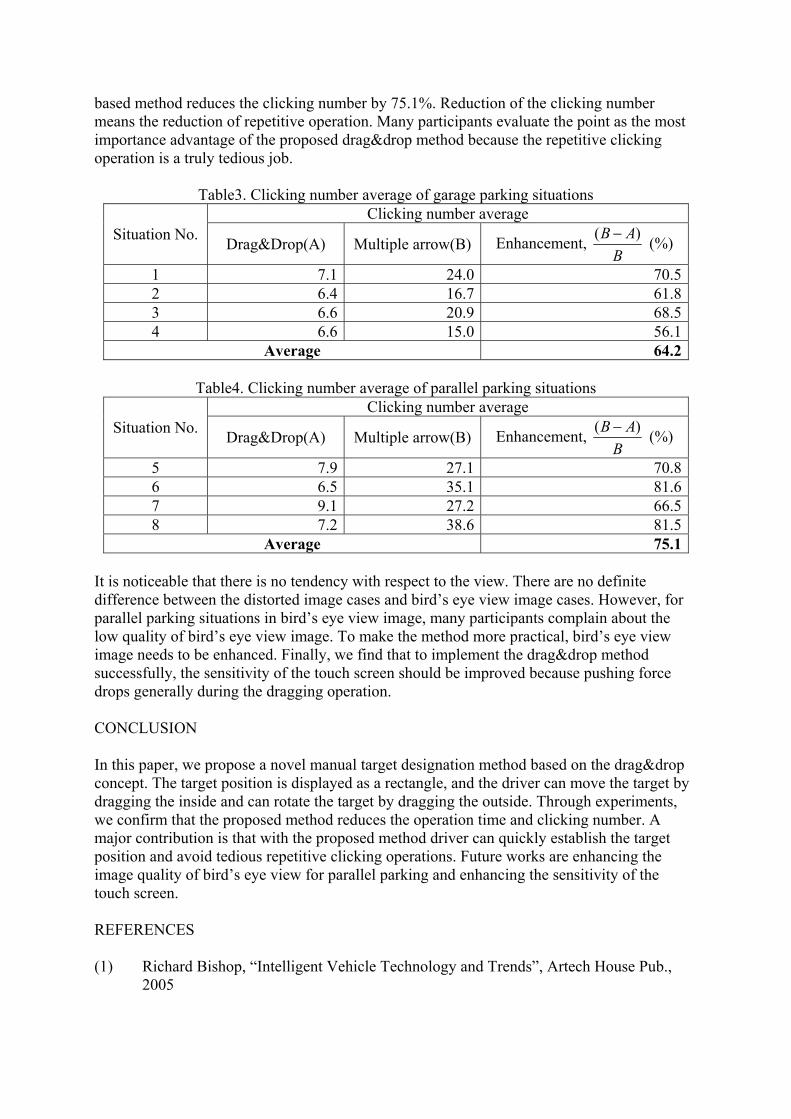
based method reduces the clicking number by 75.1%. Reduction of the clicking number means the reduction of repetitive operation. Many participants evaluate the point as the most importance advantage of the proposed drag&drop method because the repetitive clicking operation is a truly tedious job.
Table3. Clicking number average of garage parking situations Clicking number average
Situation No. Drag&Drop(A) Multiple arrow(B) Enhancement, ( )B AB− (%)
1 7.1 24.0 70.52 6.4 16.7 61.83 6.6 20.9 68.54 6.6 15.0 56.1
Average 64.2
Table4. Clicking number average of parallel parking situations Clicking number average
Situation No. Drag&Drop(A) Multiple arrow(B) Enhancement, ( )B AB− (%)
5 7.9 27.1 70.86 6.5 35.1 81.67 9.1 27.2 66.58 7.2 38.6 81.5
Average 75.1 It is noticeable that there is no tendency with respect to the view. There are no definite difference between the distorted image cases and bird’s eye view image cases. However, for parallel parking situations in bird’s eye view image, many participants complain about the low quality of bird’s eye view image. To make the method more practical, bird’s eye view image needs to be enhanced. Finally, we find that to implement the drag&drop method successfully, the sensitivity of the touch screen should be improved because pushing force drops generally during the dragging operation. CONCLUSION In this paper, we propose a novel manual target designation method based on the drag&drop concept. The target position is displayed as a rectangle, and the driver can move the target by dragging the inside and can rotate the target by dragging the outside. Through experiments, we confirm that the proposed method reduces the operation time and clicking number. A major contribution is that with the proposed method driver can quickly establish the target position and avoid tedious repetitive clicking operations. Future works are enhancing the image quality of bird’s eye view for parallel parking and enhancing the sensitivity of the touch screen. REFERENCES (1) Richard Bishop, “Intelligent Vehicle Technology and Trends”, Artech House Pub.,
2005

(2) Randy Frank, “Sensing in the Ultimately Safe Vehicle”, Society of Automotive Engineers, SAE Paper No.: 2004-21-0055, 2004
(3) Masayuki Furutani, “Obstacle Detection Systems for Vehicle Safety”, Society of Automotive Engineers, SAE Paper No.: 2004-21-0057, 2004
(4) Wei Chia Lee and Torsten Bertram, “Driver Centered Design of an Advanced Parking Assistance”, 5th European Congress and Exhibition on ITS and Services, 2005
(5) J Pohl, M Sethsson, P Degerman, and J Larsson, “A semi-automated parallel parking system for passenger cars”, Proc. ImechE, Vol. 220, Part D: J. Automobile Engineering, 2006
(6) Alexander Schanz, Andreas Spieker, and Klus-Dieter Kuhnert, “Autonomous Parking in Subterranean Garage – A look at the Position Estimation -”, IEEE Intelligent Vehicles Symposium 2003, pages: 253-258, 2003
(7) Christopher Tay Meng Keat, Cédric Pradalier, and Christian Laugier, “Vehicle Detection And Car Park Mapping Using Laser Scanner”, IEEE/RSJ International Conference on Intelligent Robots and Systems (IROS 2005), pages: 2054-2060, 2005
(8) Stefan Görner and Hermann Rohling, “Parking Lot Detection with 24GHz Radar Sensor”, 3rd International Workshop on Intelligent Transportation (WIT 2006), 2006
(9) M. Klotz, and H. Rohling, “A high range resolution radar system network for parking aid applications”, 5th International Conference on Radar Systems, 1999
(10) Massaki Wada, Kang Sup Yoon, and Hideki Hashimoto, “Development of Advanced Parking Assistance System”, IEEE Transaction on Industrial Electronics, Vol. 50, No. 1, pages: 4-17, 2003
(11) Jin Xu, Guang Chen, and Ming Xie, “Vision-Guided Automatic Parking for Smart Car”, IEEE Intelligent Vehicles Symposium 2000, pages:725-730, 2000
(12) H. G. Jung, D. S. Kim, P. J. Yoon, and J. H. Kim, “3D Vision System for the Recognition of Free Parking Site Location”, International Journal of Automotive Technology, Vol. 7, No. 3, pages: 361-367, 2006
(13) Nico Kaempchen, Uwe Franke, and Rainer Ott, “Stereo vision based pose estimation of parking lots using 3D vehicle models”, IEEE Intelligent Vehicles Sysmposium 2002, Vol. 2, pages: 459-464, 2002
(14) C. Vestri, S. Bougnoux, R. Bendahan, K. Fintzel, S. Wybo, F.Abad, and T. Kakinami, “Evalution of a Point Tracking Vision System for Parking Assistance”, 12th World Congress on ITS, 2005
(15) J. Salvi, X. Armangué, and J. Batlle, “A comparative review of camera calibration methods with accuracy evaluation”, Pattern Recognition 35(2002) 1617-1635, 2002
(16) J. Y. Bouguet, “Camera Calibration Toolbox for Matlab”, http://www.vision.caltech.edu/bouguetj/calib_doc/index.html

Q: There exists a problem in control the position of car, which is called as non holonomic constraint.
Your research is on the design of HMI for car parking; however, the problem is related to the
position control. If the user input is unacceptable in association with the constraint of position
control, how does your HMI respond to the input?
A: We developed an algorithm deciding whether current target position is proper or not. We express
the state by changing the color of target position rectangle. Therefore, driver continuously drags
target position until the target becomes feasible.