Embed Size (px)
Citation preview
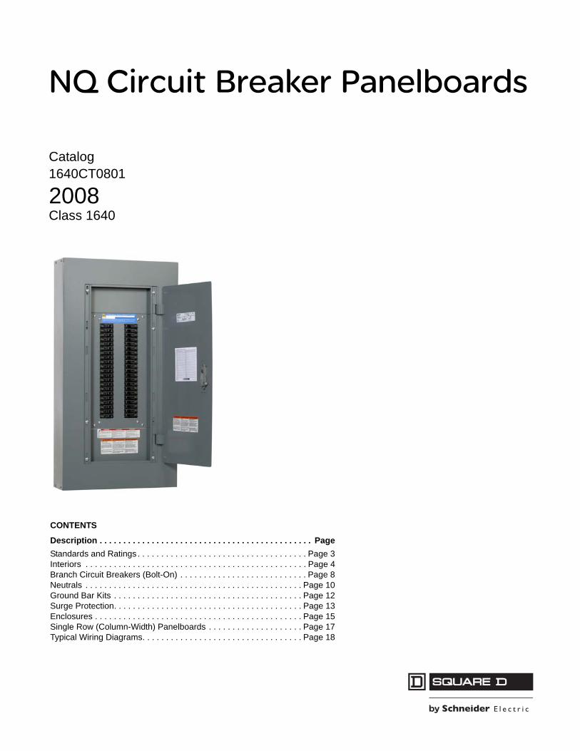
NQ Circuit Breaker Panelboards
Catalog1640CT0801
2008Class 1640
CONTENTS
Description . . . . . . . . . . . . . . . . . . . . . . . . . . . . . . . . . . . . . . . . . . . . . PageStandards and Ratings . . . . . . . . . . . . . . . . . . . . . . . . . . . . . . . . . . . . Page 3Interiors . . . . . . . . . . . . . . . . . . . . . . . . . . . . . . . . . . . . . . . . . . . . . . . Page 4Branch Circuit Breakers (Bolt-On) . . . . . . . . . . . . . . . . . . . . . . . . . . . Page 8Neutrals . . . . . . . . . . . . . . . . . . . . . . . . . . . . . . . . . . . . . . . . . . . . . . Page 10Ground Bar Kits . . . . . . . . . . . . . . . . . . . . . . . . . . . . . . . . . . . . . . . . Page 12Surge Protection. . . . . . . . . . . . . . . . . . . . . . . . . . . . . . . . . . . . . . . . Page 13Enclosures . . . . . . . . . . . . . . . . . . . . . . . . . . . . . . . . . . . . . . . . . . . . Page 15Single Row (Column-Width) Panelboards . . . . . . . . . . . . . . . . . . . . Page 17Typical Wiring Diagrams. . . . . . . . . . . . . . . . . . . . . . . . . . . . . . . . . . Page 18

NQ Circuit Breaker PanelboardsStandards and Ratings
312/2008© 2008 Schneider Electric
All Rights Reserved
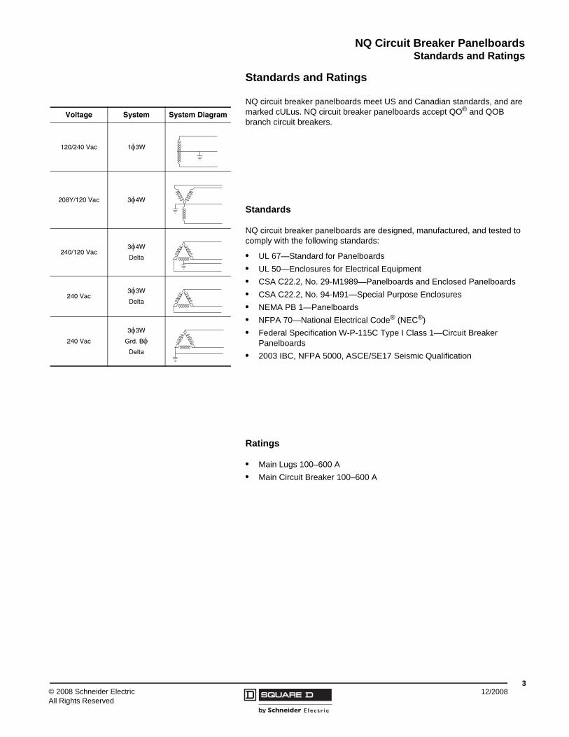
Standards and Ratings
NQ circuit breaker panelboards meet US and Canadian standards, and are marked cULus. NQ circuit breaker panelboards accept QO® and QOB branch circuit breakers.
Standards
NQ circuit breaker panelboards are designed, manufactured, and tested to comply with the following standards:
• UL 67—Standard for Panelboards• UL 50—Enclosures for Electrical Equipment• CSA C22.2, No. 29-M1989—Panelboards and Enclosed Panelboards• CSA C22.2, No. 94-M91—Special Purpose Enclosures• NEMA PB 1—Panelboards• NFPA 70—National Electrical Code® (NEC®)• Federal Specification W-P-115C Type I Class 1—Circuit Breaker
Panelboards• 2003 IBC, NFPA 5000, ASCE/SE17 Seismic Qualification
Ratings
• Main Lugs 100–600 A• Main Circuit Breaker 100–600 A
Voltage System System Diagram
120/240 Vac 1φ3W
208Y/120 Vac 3φ4W
240/120 Vac3φ4W
Delta
240 Vac3φ3W
Delta
240 Vac
3φ3W
Grd. BφDelta
© 2008 Schneider ElectricAll Rights Reserved
NQ Circuit Breaker Panelboards Interiors
412/2008
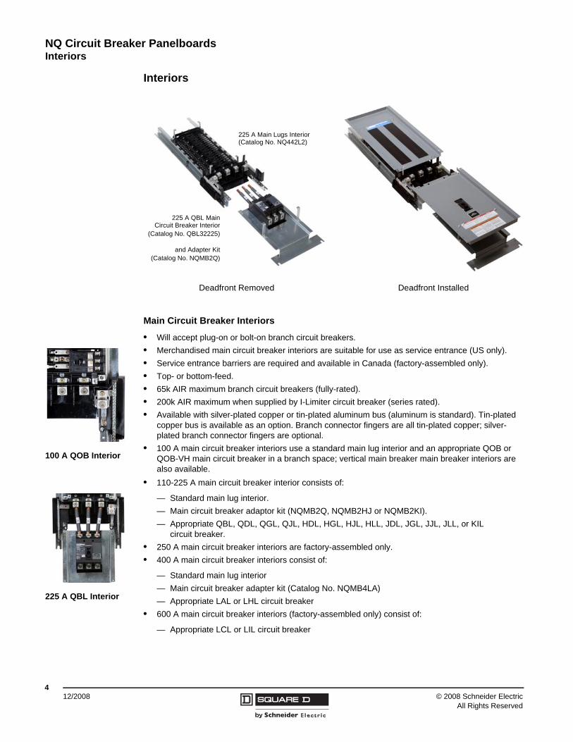
Interiors
Main Circuit Breaker Interiors
• Will accept plug-on or bolt-on branch circuit breakers.• Merchandised main circuit breaker interiors are suitable for use as service entrance (US only).• Service entrance barriers are required and available in Canada (factory-assembled only).• Top- or bottom-feed.• 65k AIR maximum branch circuit breakers (fully-rated).• 200k AIR maximum when supplied by I-Limiter circuit breaker (series rated).• Available with silver-plated copper or tin-plated aluminum bus (aluminum is standard). Tin-plated
copper bus is available as an option. Branch connector fingers are all tin-plated copper; silver-plated branch connector fingers are optional.
• 100 A main circuit breaker interiors use a standard main lug interior and an appropriate QOB or QOB-VH main circuit breaker in a branch space; vertical main breaker main breaker interiors are also available.
• 110-225 A main circuit breaker interior consists of:
— Standard main lug interior.— Main circuit breaker adaptor kit (NQMB2Q, NQMB2HJ or NQMB2KI).— Appropriate QBL, QDL, QGL, QJL, HDL, HGL, HJL, HLL, JDL, JGL, JJL, JLL, or KIL
circuit breaker.• 250 A main circuit breaker interiors are factory-assembled only.• 400 A main circuit breaker interiors consist of:
— Standard main lug interior— Main circuit breaker adapter kit (Catalog No. NQMB4LA)— Appropriate LAL or LHL circuit breaker
• 600 A main circuit breaker interiors (factory-assembled only) consist of:
— Appropriate LCL or LIL circuit breaker
225 A Main Lugs Interior(Catalog No. NQ442L2)
225 A QBL MainCircuit Breaker Interior
(Catalog No. QBL32225)
and Adapter Kit(Catalog No. NQMB2Q)
Deadfront Removed Deadfront Installed
100 A QOB Interior
225 A QBL Interior
NQ Circuit Breaker PanelboardsInteriors
512/2008© 2008 Schneider Electric
All Rights Reserved
Main circuit breakers are not included in the adapter kits, order separately.
Field-Installable Circuit Breaker Accessories
Field-installable shunt trip, alarm switch, and auxiliary contacts are available for LAL 400 A main circuit breaker interiors. Refer to the Square D Digest for additional information.
MAIN
PRINCIPAL
80110-327-03
80110-327-03
80110-327-03
80122-125-01
A B
C
I
FG
H
E
D
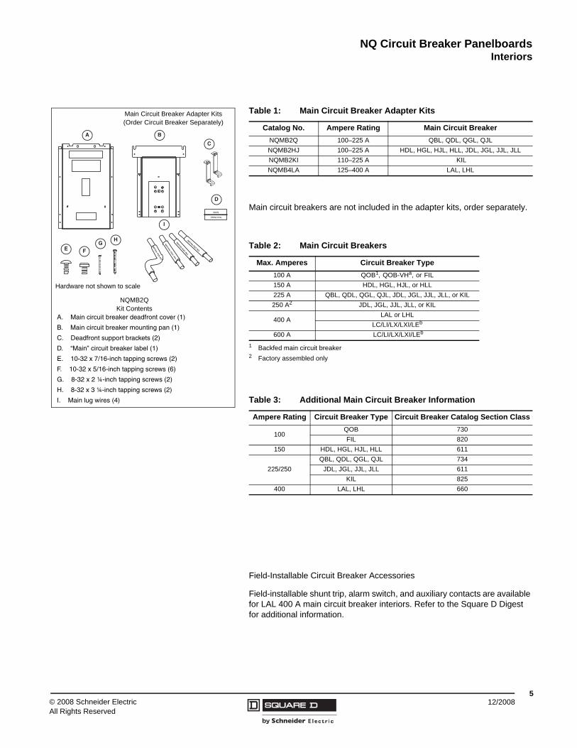
Main Circuit Breaker Adapter Kits(Order Circuit Breaker Separately)
NQMB2QKit Contents
A. Main circuit breaker deadfront cover (1)
B. Main circuit breaker mounting pan (1)
C. Deadfront support brackets (2)
D. “Main” circuit breaker label (1)
E. 10-32 x 7/16-inch tapping screws (2)
F. 10-32 x 5/16-inch tapping screws (6)
G. 8-32 x 2 ¼-inch tapping screws (2)
H. 8-32 x 3 ¼-inch tapping screws (2)
I. Main lug wires (4)
Hardware not shown to scale
Table 1: Main Circuit Breaker Adapter Kits
Catalog No. Ampere Rating Main Circuit BreakerNQMB2Q 100–225 A QBL, QDL, QGL, QJLNQMB2HJ 100–225 A HDL, HGL, HJL, HLL, JDL, JGL, JJL, JLLNQMB2KI 110–225 A KILNQMB4LA 125–400 A LAL, LHL
Table 2: Main Circuit Breakers
Max. Amperes Circuit Breaker Type100 A QOB1, QOB-VHa, or FIL
1 Backfed main circuit breaker
150 A HDL, HGL, HJL, or HLL225 A QBL, QDL, QGL, QJL, JDL, JGL, JJL, JLL, or KIL250 A2
2 Factory assembled only
JDL, JGL, JJL, JLL, or KIL
400 ALAL or LHL
LC/LI/LX/LXI/LEb
600 A LC/LI/LX/LXI/LEb
Table 3: Additional Main Circuit Breaker Information
Ampere Rating Circuit Breaker Type Circuit Breaker Catalog Section Class
100QOB 730FIL 820
150 HDL, HGL, HJL, HLL 611
225/250QBL, QDL, QGL, QJL 734
JDL, JGL, JJL, JLL 611KIL 825
400 LAL, LHL 660
NQ Circuit Breaker PanelboardsInteriors
© 2008 Schneider ElectricAll Rights Reserved
612/2008
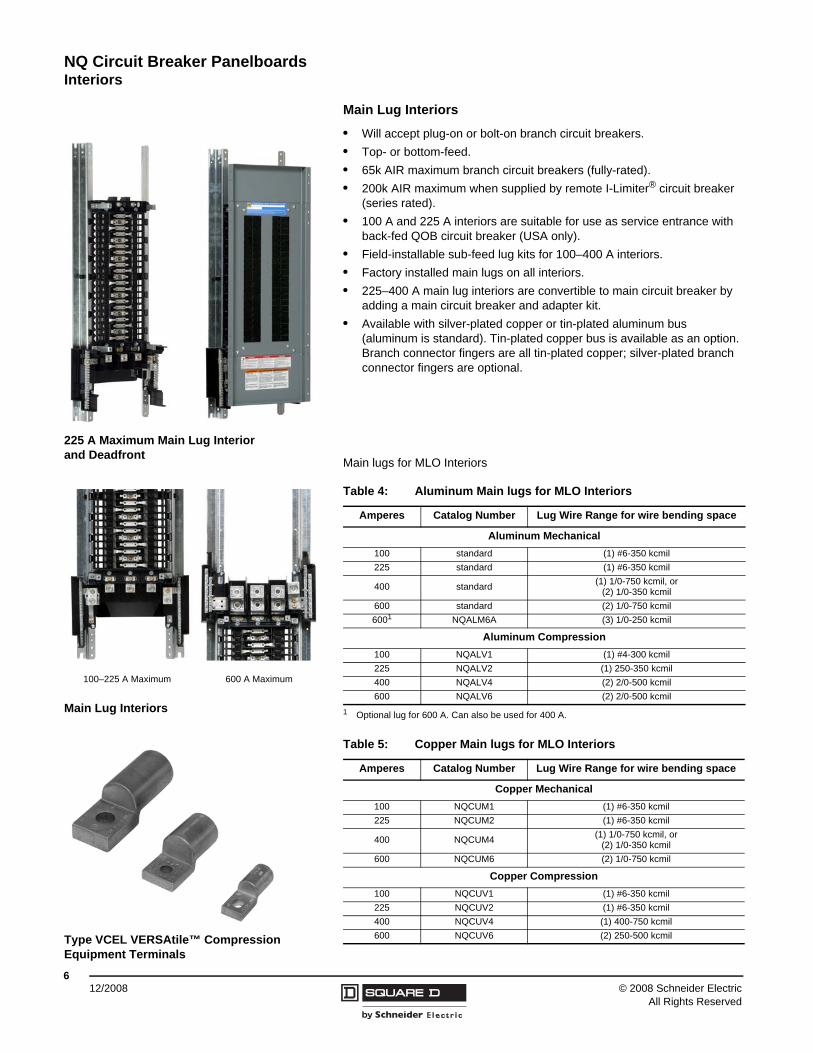
Main Lug Interiors
• Will accept plug-on or bolt-on branch circuit breakers.• Top- or bottom-feed.• 65k AIR maximum branch circuit breakers (fully-rated).• 200k AIR maximum when supplied by remote I-Limiter® circuit breaker
(series rated).• 100 A and 225 A interiors are suitable for use as service entrance with
back-fed QOB circuit breaker (USA only).• Field-installable sub-feed lug kits for 100–400 A interiors.• Factory installed main lugs on all interiors.• 225–400 A main lug interiors are convertible to main circuit breaker by
adding a main circuit breaker and adapter kit.• Available with silver-plated copper or tin-plated aluminum bus
(aluminum is standard). Tin-plated copper bus is available as an option. Branch connector fingers are all tin-plated copper; silver-plated branch connector fingers are optional.
Main lugs for MLO Interiors
225 A Maximum Main Lug Interiorand Deadfront
Main Lug Interiors
100–225 A Maximum 600 A Maximum
Table 4: Aluminum Main lugs for MLO Interiors
Amperes Catalog Number Lug Wire Range for wire bending space
Aluminum Mechanical100 standard (1) #6-350 kcmil225 standard (1) #6-350 kcmil
400 standard (1) 1/0-750 kcmil, or (2) 1/0-350 kcmil
600 standard (2) 1/0-750 kcmil6001
1 Optional lug for 600 A. Can also be used for 400 A.
NQALM6A (3) 1/0-250 kcmil
Aluminum Compression100 NQALV1 (1) #4-300 kcmil225 NQALV2 (1) 250-350 kcmil400 NQALV4 (2) 2/0-500 kcmil600 NQALV6 (2) 2/0-500 kcmil
Type VCEL VERSAtile™ CompressionEquipment Terminals
Table 5: Copper Main lugs for MLO Interiors
Amperes Catalog Number Lug Wire Range for wire bending space
Copper Mechanical100 NQCUM1 (1) #6-350 kcmil225 NQCUM2 (1) #6-350 kcmil
400 NQCUM4 (1) 1/0-750 kcmil, or (2) 1/0-350 kcmil
600 NQCUM6 (2) 1/0-750 kcmil
Copper Compression100 NQCUV1 (1) #6-350 kcmil225 NQCUV2 (1) #6-350 kcmil400 NQCUV4 (1) 400-750 kcmil600 NQCUV6 (2) 250-500 kcmil
NQ Circuit Breaker PanelboardsInteriors
712/2008© 2008 Schneider Electric
All Rights Reserved
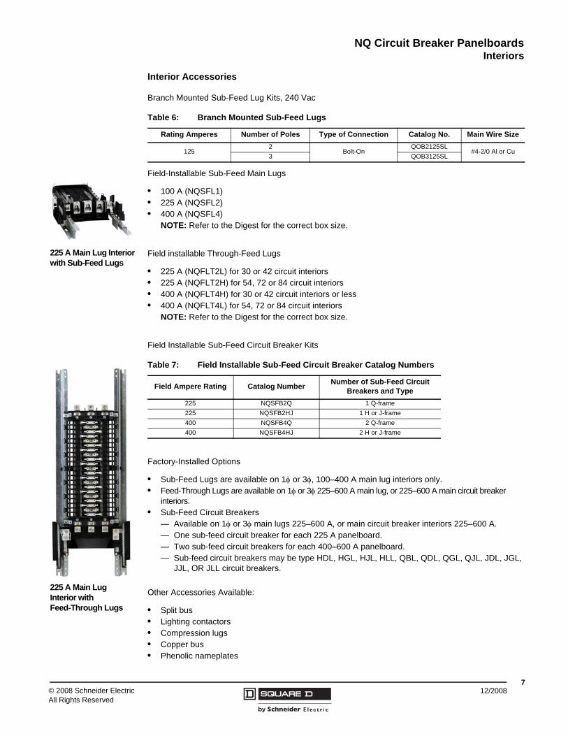
Interior Accessories
Branch Mounted Sub-Feed Lug Kits, 240 Vac
Field-Installable Sub-Feed Main Lugs
• 100 A (NQSFL1)• 225 A (NQSFL2)• 400 A (NQSFL4)
NOTE: Refer to the Digest for the correct box size.
Field installable Through-Feed Lugs
• 225 A (NQFLT2L) for 30 or 42 circuit interiors• 225 A (NQFLT2H) for 54, 72 or 84 circuit interiors• 400 A (NQFLT4H) for 30 or 42 circuit interiors or less• 400 A (NQFLT4L) for 54, 72 or 84 circuit interiors
NOTE: Refer to the Digest for the correct box size.
Field Installable Sub-Feed Circuit Breaker Kits
Factory-Installed Options
• Sub-Feed Lugs are available on 1φ or 3φ, 100–400 A main lug interiors only.• Feed-Through Lugs are available on 1φ or 3φ 225–600 A main lug, or 225–600 A main circuit breaker
interiors.• Sub-Feed Circuit Breakers
— Available on 1φ or 3φ main lugs 225–600 A, or main circuit breaker interiors 225–600 A.— One sub-feed circuit breaker for each 225 A panelboard.— Two sub-feed circuit breakers for each 400–600 A panelboard.— Sub-feed circuit breakers may be type HDL, HGL, HJL, HLL, QBL, QDL, QGL, QJL, JDL, JGL,
JJL, OR JLL circuit breakers.
Other Accessories Available:
• Split bus• Lighting contactors• Compression lugs• Copper bus• Phenolic nameplates
Table 6: Branch Mounted Sub-Feed Lugs
Rating Amperes Number of Poles Type of Connection Catalog No. Main Wire Size
1252
Bolt-OnQOB2125SL
#4-2/0 Al or Cu3 QOB3125SL
225 A Main Lug Interiorwith Sub-Feed Lugs
225 A Main LugInterior with Feed-Through Lugs
Table 7: Field Installable Sub-Feed Circuit Breaker Catalog Numbers
Field Ampere Rating Catalog Number Number of Sub-Feed Circuit Breakers and Type
225 NQSFB2Q 1 Q-frame225 NQSFB2HJ 1 H or J-frame400 NQSFB4Q 2 Q-frame400 NQSFB4HJ 2 H or J-frame
© 2008 Schneider ElectricAll Rights Reserved
NQ Circuit Breaker Panelboards Branch Circuit Breakers (Bolt-on)
812/2008
Branch Circuit Breakers (Bolt-on)
Table 8: Branch Circuit Breakers (Plug-on or Bolt-on) 1
1 Series ratings are also available. Canada: See the Series Rating Guide (data bulletin #S1600PD0302EP) USA: See Switchboard/Panelboard Short-Circuit Current Ratings (data bulletin #2700DB9901), or the Digest
10 k AIR 22 k AIR 65 k AIR 10 k AIR (240 Vac) 42 k AIR
QO, QOB QO-VH, QOB-VH QH, QHB QO-H, QOB-H QOH1-Pole 10–70 A 1-Pole 15–30 A 1-Pole 15–30 A
2-Pole 15–100 A 2-Pole 35–125 A2-Pole 10–125 A 2-Pole 15–150 A 2-Pole 15–30 A3-Pole 10–100 A 3-Pole 15–150 A 3-Pole 15–30 A
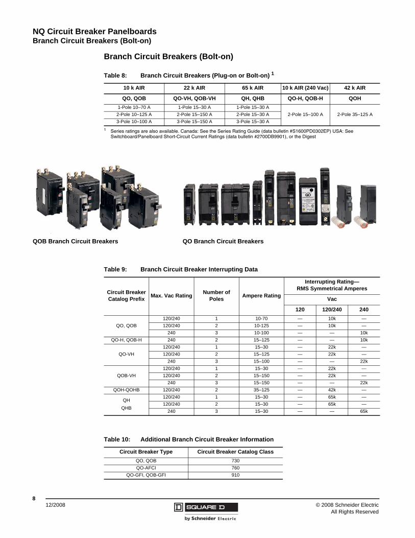
QOB Branch Circuit Breakers QO Branch Circuit Breakers
Table 9: Branch Circuit Breaker Interrupting Data
Circuit Breaker Catalog Prefix Max. Vac Rating Number of
Poles Ampere Rating
Interrupting Rating—RMS Symmetrical Amperes
Vac
120 120/240 240
QO, QOB120/240 1 10-70 — 10k —120/240 2 10-125 — 10k —
240 3 10-100 — — 10kQO-H, QOB-H 240 2 15–125 — — 10k
QO-VH120/240 1 15–30 — 22k —120/240 2 15–125 — 22k —
240 3 15–100 — — 22k
QOB-VH120/240 1 15–30 — 22k —120/240 2 15–150 — 22k —
240 3 15–150 — — 22kQOH-QOHB 120/240 2 35–125 — 42k —
QHQHB
120/240 1 15–30 — 65k —120/240 2 15–30 — 65k —
240 3 15–30 — — 65k
Table 10: Additional Branch Circuit Breaker Information
Circuit Breaker Type Circuit Breaker Catalog ClassQO, QOB 730QO-AFCI 760
QO-GFI, QOB-GFI 910
NQ Circuit Breaker PanelboardsBranch Circuit Breakers (Bolt-on)
912/2008© 2008 Schneider Electric
All Rights Reserved
QO® Arc-Fault Circuit Breakers1
QO arc-fault circuit breakers provide branch feeder protection (i.e., QO115AFI) or combination protection (i.e. QO115CAFI) as required by the NEC and local code adoption, and comply with UL 1699.
NOTE:
• Lugs suitable for 75° C wire.• Torque QOB connector mounting screws to 18–21 lb-in.• Torque labels are included on the circuit breakers with load side lug torque requirements.
1 HACR type for use with air conditioning, heating and refrigeration equipment having motor group combinations and marked for use with HACR type circuit breakers.
Table 11: QO Arc-Fault Circuit Breaker Catalog Numbers
Circuit Breaker Type Ampere Rating
1P 120 Vac 10 kAIR1 Space Required
1P 120 Vac 22 kAIR1 Space Required
Catalog Number Catalog Number
Branch Feeder Arc-Fault Interrupter
15 QO115AFI QO115VHAFI20 QO120AFI QO120VHAFI
Combination Arc-Fault Interrupter
15 QO115CAFI QO115VCAFI20 QO120CAFI QO120VHCAFI
Table 12: Branch Circuit Breaker Lug Data
Ampere Rating Circuit Breaker TypeWire Size
Aluminum Copper10–30 QO, QOB (2) #12-#8 (2) #14-#835–50 QO, QOB (1) #8-#4 (1) #8-#460–70 QO, QOB (1) #6-#2 (2) #6-#2
80–125 QO, QOB (1) #4-2/0 (1) #4-2/0150 QOB-VH (1) #4-300 kcmil (1) #4-300 kcmil
© 2008 Schneider ElectricAll Rights Reserved
NQ Circuit Breaker Panelboards Neutrals
1012/2008
Neutrals• All lugs suitable for copper or aluminum wire.100–600 A interiors have split neutral located on
same end as mains.• Bondable for use as service entrance (in Canada, available as factory-assembled only).• Branch terminals suitable for #12-#4 aluminum and #14-#4 copper.• Provisions for larger branch terminal lugs with use of auxiliary neutral lugs.• Suitable lug provided on neutrals for termination of grounding conductor.• All unused neutral terminals may be used to terminate equipment grounding conductors when
panelboard is used as service entrance.• 100% rated neutrals. One neutral termination provided per circuit in panelboard.• 200% rated neutrals are available as factory-assembled options or as kits.
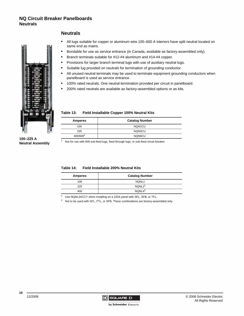
100–225 ANeutral Assembly
Table 13: Field Installable Copper 100% Neutral Kits
Amperes Catalog Number
100 NQN1CU
225 NQN2CU
400/6001
1 Not for use with 600 sub-feed lugs, feed-through lugs, or sub-feed circuit breaker
NQN6CU
Table 14: Field Installable 200% Neutral Kits
Amperes Catalog Number
100 NQNL1
225 NQNL21
1 Use NQNL2ACCY when installing on a 225A panel with SFL, SFB, or TFL.
400 NQNL42
2 Not to be used with SFL, FTL, or SFB. These combinations are factory-assembled only.
NQ Circuit Breaker PanelboardsNeutrals
1112/2008© 2008 Schneider Electric
All Rights Reserved
200% Neutral Restrictions
225 A, 200% Neutral
• Integral lighting contactors are not available.• Crimp neutral line lugs are not available.• If sub-feed lugs, feed-through lugs, or sub-feed circuit breakers are
required, order the following 200% neutral kit: NQNL2ACCY
400 A, 200% Neutral
• Type 3R, 5, and 12 enclosures require copper-bussed interiors.• Sub-feed circuit breakers are available with main lug interiors in Type 1
enclosures only. Sub-feed circuit breakers are not available in Type 3R, 4, 4X, 5, and 12 enclosures.
• Using a sub-feed circuit breaker restricts standard QO and QOB branches to a maximum of 125 A.
• Integral lighting contactors are not available.• Crimp neutral line lugs are not available.• 400 A panelboards equipped with 200% neutrals and sub-feed lugs,
feed-through lugs, or sub-feed circuit breakers are only available factory-assembled.
Auxiliary Neutral Lugs
Lugs are suitable for copper or aluminum wire and are field-installable on neutral assembly.
Neutral Bonding Provisions
Bonding strap may be field-installed for UL service equipment requirements on 100–400 A interiors (in Canada, available as factory-assembled only).
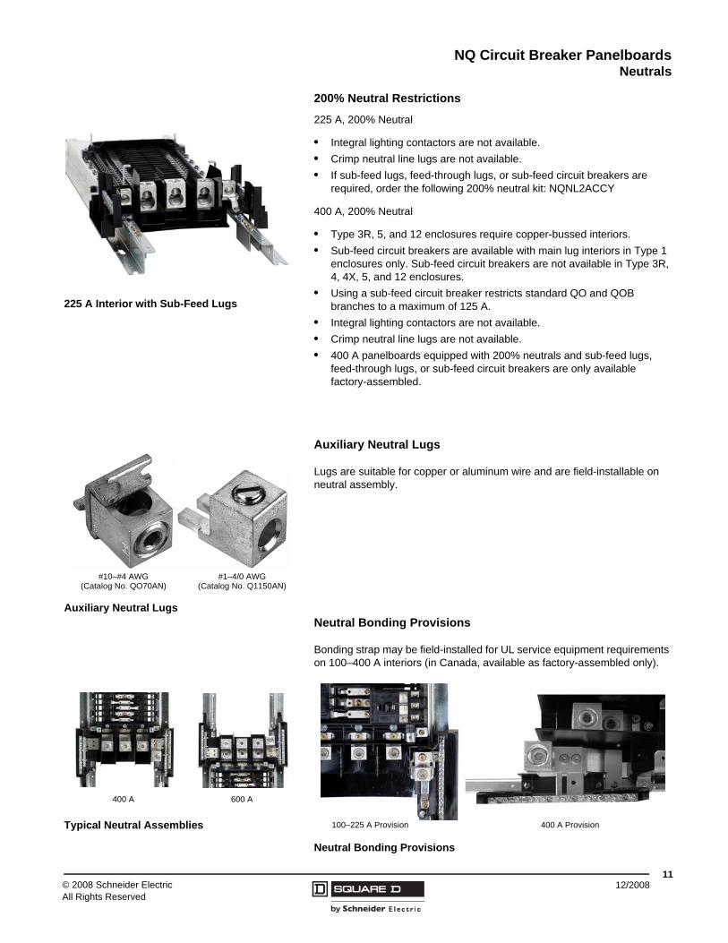
225 A Interior with Sub-Feed Lugs
Auxiliary Neutral Lugs
#10–#4 AWG(Catalog No. QO70AN)
#1–4/0 AWG(Catalog No. Q1150AN)
Typical Neutral Assemblies
400 A 600 A
Neutral Bonding Provisions
100–225 A Provision 400 A Provision
NQ Circuit Breaker PanelboardsGround Bar Kits
© 2008 Schneider ElectricAll Rights Reserved
1212/2008
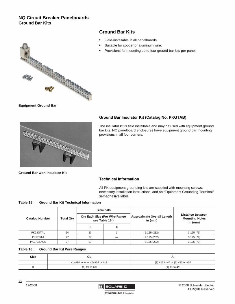
Ground Bar Kits• Field-installable in all panelboards.• Suitable for copper or aluminum wire.• Provisions for mounting up to four ground bar kits per panel.
Ground Bar Insulator Kit (Catalog No. PKGTAB)
The insulator kit is field installable and may be used with equipment ground bar kits. NQ panelboard enclosures have equipment ground bar mounting provisions in all four corners.
Technical Information
All PK equipment grounding kits are supplied with mounting screws, necessary installation instructions, and an “Equipment Grounding Terminal” self-adhesive label.
Equipment Ground Bar
Ground Bar with Insulator Kit
Table 15: Ground Bar Kit Technical Information
Catalog Number Total Qty
Terminals
Approximate Overall Length in (mm)
Distance Between Mounting Holes
in (mm)
Qty Each Size (For Wire Range see Table 16:)
I II
PK23GTAL 24 23 1 9.125 (232) 3.125 (79)
PK27GTA 27 27 — 9.125 (232) 3.125 (79)
PK27GTACU 27 27 — 9.125 (232) 3.125 (79)
Table 16: Ground Bar Kit Wire Ranges
Size Cu Al
I (1) #14 to #4 or (2) #14 or #12 (1) #12 to #4 or (2) #12 or #10
II (1) #1 to 4/0 (1) #1 to 4/0
NQ Circuit Breaker PanelboardsSurge Protection
1312/2008© 2008 Schneider Electric
All Rights Reserved
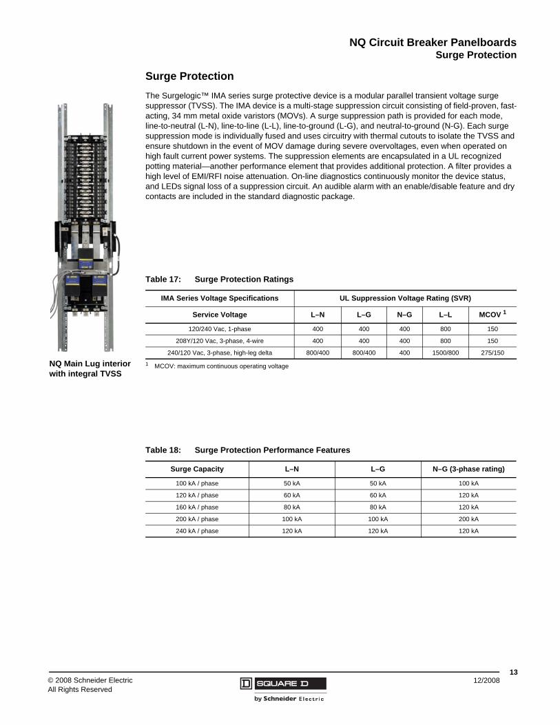
Surge ProtectionThe Surgelogic™ IMA series surge protective device is a modular parallel transient voltage surge suppressor (TVSS). The IMA device is a multi-stage suppression circuit consisting of field-proven, fast-acting, 34 mm metal oxide varistors (MOVs). A surge suppression path is provided for each mode, line-to-neutral (L-N), line-to-line (L-L), line-to-ground (L-G), and neutral-to-ground (N-G). Each surge suppression mode is individually fused and uses circuitry with thermal cutouts to isolate the TVSS and ensure shutdown in the event of MOV damage during severe overvoltages, even when operated on high fault current power systems. The suppression elements are encapsulated in a UL recognized potting material—another performance element that provides additional protection. A filter provides a high level of EMI/RFI noise attenuation. On-line diagnostics continuously monitor the device status, and LEDs signal loss of a suppression circuit. An audible alarm with an enable/disable feature and dry contacts are included in the standard diagnostic package.
NQ Main Lug interiorwith integral TVSS
Table 17: Surge Protection Ratings
IMA Series Voltage Specifications UL Suppression Voltage Rating (SVR)
Service Voltage L–N L–G N–G L–L MCOV 1
1 MCOV: maximum continuous operating voltage
120/240 Vac, 1-phase 400 400 400 800 150
208Y/120 Vac, 3-phase, 4-wire 400 400 400 800 150
240/120 Vac, 3-phase, high-leg delta 800/400 800/400 400 1500/800 275/150
Table 18: Surge Protection Performance Features
Surge Capacity L–N L–G N–G (3-phase rating)
100 kA / phase 50 kA 50 kA 100 kA
120 kA / phase 60 kA 60 kA 120 kA
160 kA / phase 80 kA 80 kA 120 kA
200 kA / phase 100 kA 100 kA 200 kA
240 kA / phase 120 kA 120 kA 120 kA
© 2008 Schneider ElectricAll Rights Reserved
NQ Circuit Breaker Panelboards Surge Protection
1412/2008
Design Features
• Individually fused suppression modules• Thermal cutout• Inline, copper bus bar connection• Solid state bi-directional• Push-to-Test on-line diagnostic display• Audible alarm with enable/disable switch• LED indicators indicate loss of protection, or fully-operational circuit• High-energy parallel design for IEEE C62.41 category A, B, and C3 applications• Available in main circuit breaker and main lug only panelboards with sub-feed circuit breakers,
feed-through lugs, or sub-feed lugs.• AC tracking filter with EMI/RFI filtering up to -30 dB from 100 kHz to 100 MHz
Table 19: Surge Protection Specifications
Relative Humidity 0 to 95% non-condensing
Operating Frequency 47–63 Hz
Storage Temperature -40° to +65° C (-40° to +149° F)
Operating Temperature -40° to +65° C (-40° to +149° F)
Display Operating Temperature -10° to +50° C (+14° to +122° F)
Standards UL 1449 Second Edition: UL Category Section 37.3 (200 kA short-circuit current module rating)
Fusing Individually fused suppression modules
Audible Alarm Provides audible indication that there is a loss of protection
Dry Contacts Provides remote indication of the TVSS device’s operating status to a computer interface board or emergency management system
Table 20: Other Surge Protection Options
Option Description
Surge Counter Displays the combined total number of transient voltage surges detected from L–G, L–L, L–N, and N–G since the counter was last reset.
Remote Monitor Displays the alarm status of the surge protective device up to 1,000 ft (305 m) away from the unit. This option uses the dry contacts.
NQ Circuit Breaker PanelboardsEnclosures
1512/2008© 2008 Schneider Electric
All Rights Reserved
Enclosures
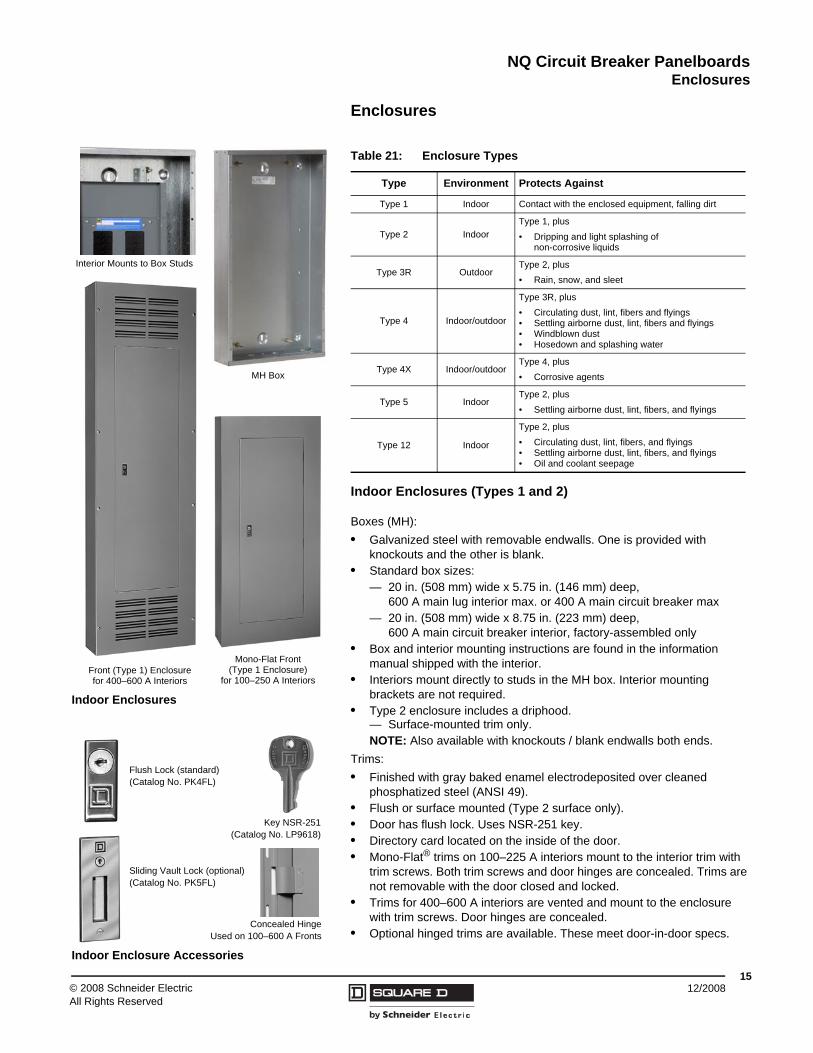
Indoor Enclosures (Types 1 and 2)
Boxes (MH):• Galvanized steel with removable endwalls. One is provided with
knockouts and the other is blank.• Standard box sizes:
— 20 in. (508 mm) wide x 5.75 in. (146 mm) deep, 600 A main lug interior max. or 400 A main circuit breaker max
— 20 in. (508 mm) wide x 8.75 in. (223 mm) deep, 600 A main circuit breaker interior, factory-assembled only
• Box and interior mounting instructions are found in the information manual shipped with the interior.
• Interiors mount directly to studs in the MH box. Interior mounting brackets are not required.
• Type 2 enclosure includes a driphood.— Surface-mounted trim only.NOTE: Also available with knockouts / blank endwalls both ends.
Trims:• Finished with gray baked enamel electrodeposited over cleaned
phosphatized steel (ANSI 49).• Flush or surface mounted (Type 2 surface only).• Door has flush lock. Uses NSR-251 key.• Directory card located on the inside of the door.• Mono-Flat® trims on 100–225 A interiors mount to the interior trim with
trim screws. Both trim screws and door hinges are concealed. Trims are not removable with the door closed and locked.
• Trims for 400–600 A interiors are vented and mount to the enclosure with trim screws. Door hinges are concealed.
• Optional hinged trims are available. These meet door-in-door specs.
Indoor Enclosures
Front (Type 1) Enclosure for 400–600 A Interiors
Mono-Flat Front(Type 1 Enclosure)
for 100–250 A Interiors
Interior Mounts to Box Studs
MH Box
Table 21: Enclosure Types
Type Environment Protects Against
Type 1 Indoor Contact with the enclosed equipment, falling dirt
Type 2 IndoorType 1, plus• Dripping and light splashing of
non-corrosive liquids
Type 3R OutdoorType 2, plus• Rain, snow, and sleet
Type 4 Indoor/outdoor
Type 3R, plus• Circulating dust, lint, fibers and flyings• Settling airborne dust, lint, fibers and flyings• Windblown dust• Hosedown and splashing water
Type 4X Indoor/outdoorType 4, plus • Corrosive agents
Type 5 IndoorType 2, plus • Settling airborne dust, lint, fibers, and flyings
Type 12 Indoor
Type 2, plus• Circulating dust, lint, fibers, and flyings• Settling airborne dust, lint, fibers, and flyings• Oil and coolant seepage
Indoor Enclosure Accessories
Key NSR-251(Catalog No. LP9618)
Concealed HingeUsed on 100–600 A Fronts
Flush Lock (standard)(Catalog No. PK4FL)
Sliding Vault Lock (optional)(Catalog No. PK5FL)
NQ Circuit Breaker PanelboardsEnclosures
© 2008 Schneider ElectricAll Rights Reserved
1612/2008
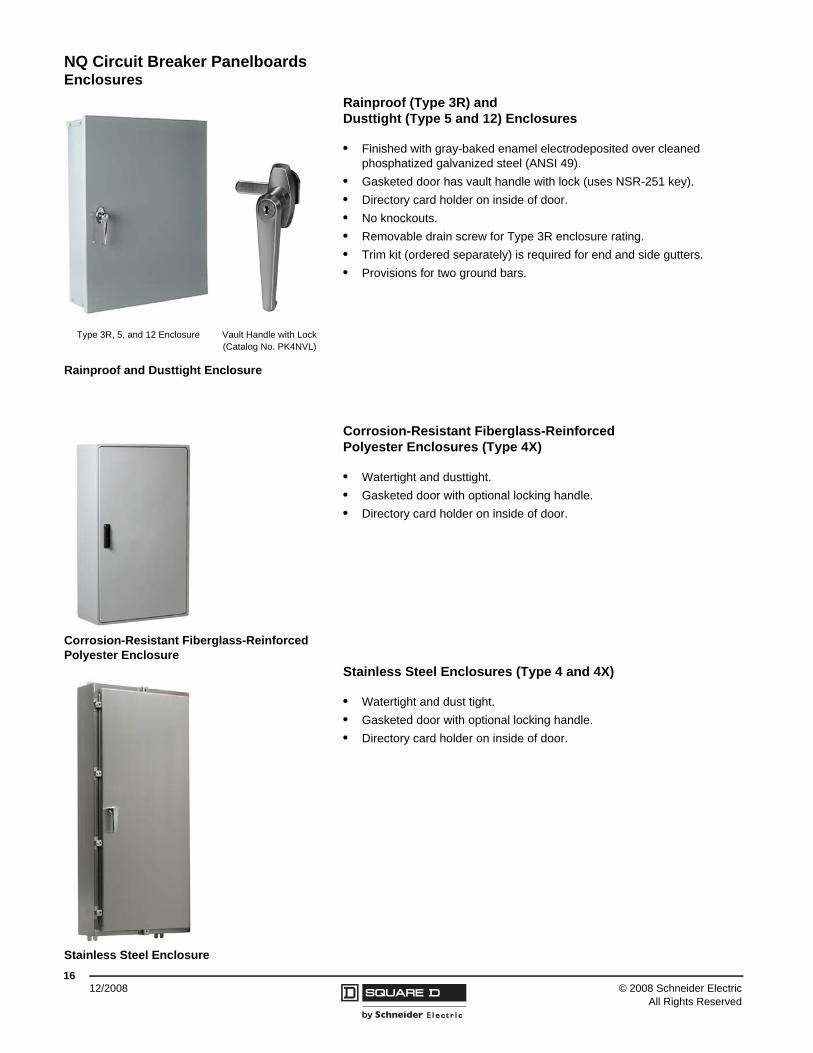
Rainproof (Type 3R) and Dusttight (Type 5 and 12) Enclosures
• Finished with gray-baked enamel electrodeposited over cleaned phosphatized galvanized steel (ANSI 49).
• Gasketed door has vault handle with lock (uses NSR-251 key).• Directory card holder on inside of door.• No knockouts.• Removable drain screw for Type 3R enclosure rating.• Trim kit (ordered separately) is required for end and side gutters.• Provisions for two ground bars.
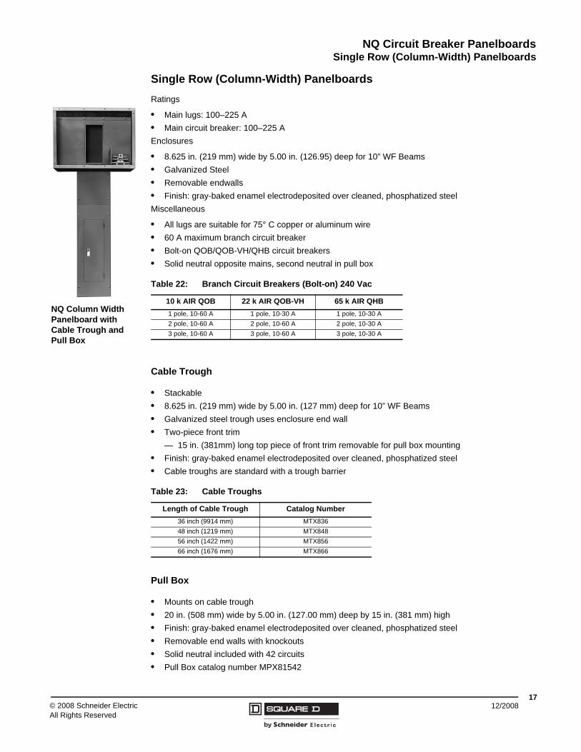
Corrosion-Resistant Fiberglass-Reinforced Polyester Enclosures (Type 4X)
• Watertight and dusttight.• Gasketed door with optional locking handle.• Directory card holder on inside of door.
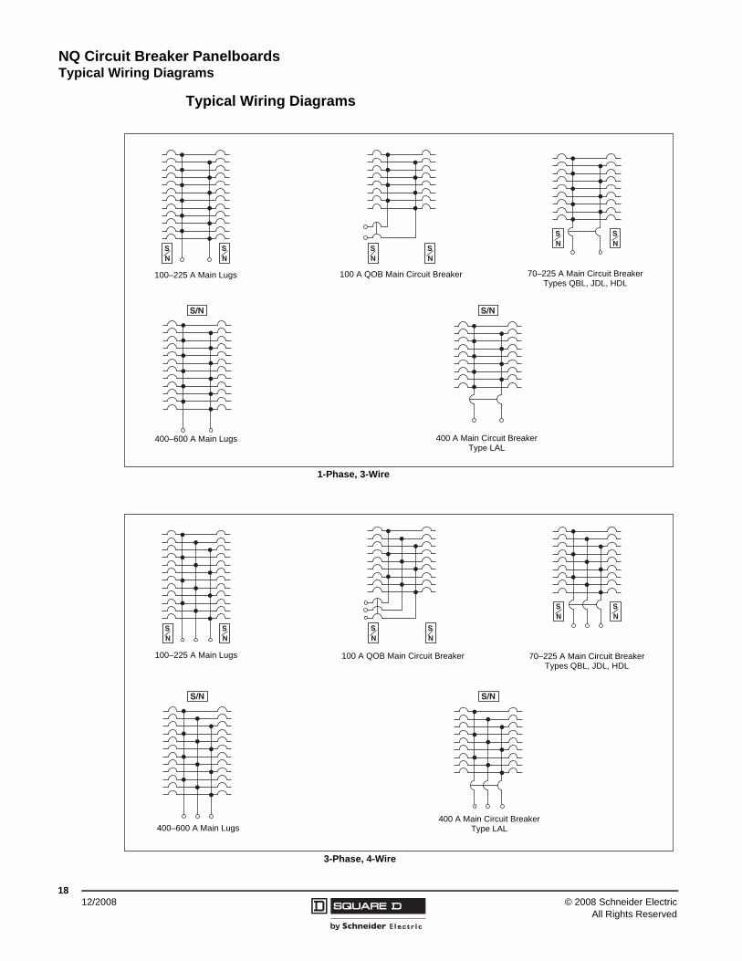
Stainless Steel Enclosures (Type 4 and 4X)
• Watertight and dust tight.• Gasketed door with optional locking handle.• Directory card holder on inside of door.
Rainproof and Dusttight Enclosure
Type 3R, 5, and 12 Enclosure Vault Handle with Lock(Catalog No. PK4NVL)
Corrosion-Resistant Fiberglass-ReinforcedPolyester Enclosure
Stainless Steel Enclosure
NQ Circuit Breaker PanelboardsSingle Row (Column-Width) Panelboards
1712/2008© 2008 Schneider Electric
All Rights Reserved
Single Row (Column-Width) PanelboardsRatings
• Main lugs: 100–225 A• Main circuit breaker: 100–225 AEnclosures
• 8.625 in. (219 mm) wide by 5.00 in. (126.95) deep for 10” WF Beams• Galvanized Steel• Removable endwalls• Finish: gray-baked enamel electrodeposited over cleaned, phosphatized steelMiscellaneous
• All lugs are suitable for 75° C copper or aluminum wire• 60 A maximum branch circuit breaker• Bolt-on QOB/QOB-VH/QHB circuit breakers• Solid neutral opposite mains, second neutral in pull box
Cable Trough
• Stackable• 8.625 in. (219 mm) wide by 5.00 in. (127 mm) deep for 10” WF Beams• Galvanized steel trough uses enclosure end wall• Two-piece front trim
— 15 in. (381mm) long top piece of front trim removable for pull box mounting• Finish: gray-baked enamel electrodeposited over cleaned, phosphatized steel• Cable troughs are standard with a trough barrier
Pull Box
• Mounts on cable trough• 20 in. (508 mm) wide by 5.00 in. (127.00 mm) deep by 15 in. (381 mm) high• Finish: gray-baked enamel electrodeposited over cleaned, phosphatized steel• Removable end walls with knockouts• Solid neutral included with 42 circuits• Pull Box catalog number MPX81542
NQ Column WidthPanelboard withCable Trough andPull Box
Table 22: Branch Circuit Breakers (Bolt-on) 240 Vac
10 k AIR QOB 22 k AIR QOB-VH 65 k AIR QHB1 pole, 10-60 A 1 pole, 10-30 A 1 pole, 10-30 A2 pole, 10-60 A 2 pole, 10-60 A 2 pole, 10-30 A3 pole, 10-60 A 3 pole, 10-60 A 3 pole, 10-30 A
Table 23: Cable Troughs
Length of Cable Trough Catalog Number36 inch (9914 mm) MTX83648 inch (1219 mm) MTX84856 inch (1422 mm) MTX85666 inch (1676 mm) MTX866
© 2008 Schneider ElectricAll Rights Reserved
NQ Circuit Breaker Panelboards Typical Wiring Diagrams
1812/2008
Typical Wiring Diagrams
SN
SN
S/N S/N
SN
SN
SN
SN
SN
SN
SN
SN
SN
SN
S/N S/N
100–225 A Main Lugs
400–600 A Main Lugs
100 A QOB Main Circuit Breaker 70–225 A Main Circuit BreakerTypes QBL, JDL, HDL
400 A Main Circuit BreakerType LAL
1-Phase, 3-Wire
100–225 A Main Lugs
3-Phase, 4-Wire
100 A QOB Main Circuit Breaker 70–225 A Main Circuit BreakerTypes QBL, JDL, HDL
400–600 A Main Lugs400 A Main Circuit Breaker
Type LAL
Notes

Notes
Notes

Notes


1640CT0801 © 2008 Schneider Electric. All Rights Reserved.
Schneider Electric USA252 North TippecanoePeru, IN 46970 USA1-888-SquareD (1-888-778-2733)www.schneider-electric.us
Schneider Electric Canada19 Waterman Avenue,M4B 1 Y2Toronto, Ontario1-800-565-6699www.schneider-electric.ca
12/2008