Embed Size (px)
Citation preview

NUCLEAR POWER PLANT CORE MATERIALS AND FABRICATION'
C m m s T m teachers frequently find it helpful to illustrate background material by pointing out the use to which chemical knowledge is put in the practical world. In this connection it may be of some interest to discuss nuclear power plant core materials and their fabrication.
The nuclear power industry has developed special meanings for certain words. For clarity some of these terms are here defined.
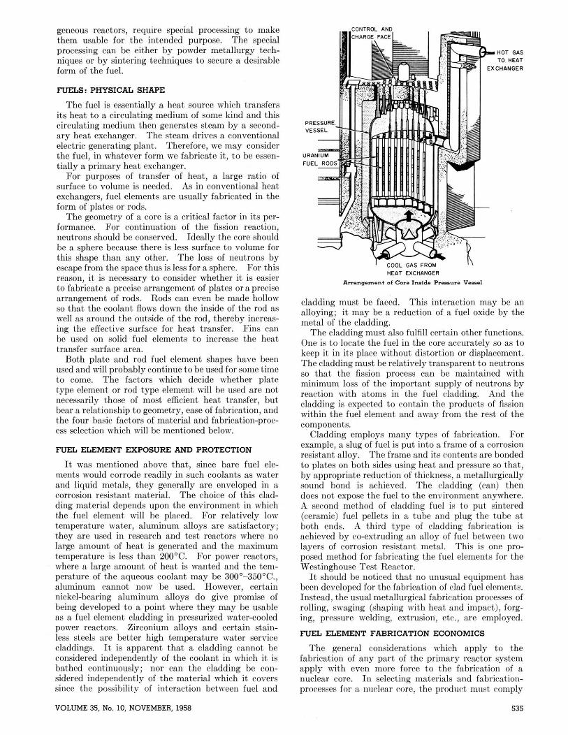
The core is the place where heat is generated by nuclear fission. As distinguished from a homogeneous reactor whose core is a special zone in the primary heat transfer piping system ("loop"), a heterogeneous re- actor contains a core which is a primary heat exchanger containing the source of energy. Such a core is made up of fuel, control rods, structural materials, moderator, and coolant.
The fissionable fuel which supplies energy is in some form selected on the basis of the physics and economics of the chosen plant design. The fuel is processed and fabricated (it will later be reprocessed) for minimum capital aud operating cost.
The core contains neutron-absorbing control rods which are made of materials which have to be fabri- cated in a design suitable for use in the core. Struc- tural materials hold the core in place in the primary vessel. Moderators slow down fast neutrons arising from the continuing fission reaction to a useful speed. Coolants transfer heat to a steam generator. Thermal shields protect the pressure vessel from excessive gamma-ray heating and contribute a worth-while quantity of heat to the coolant by their response to gamma ray bombardment.
The nuclear reactor is nothing more or less than a source of energy which in some way or other is trans- ferred to a steam generator. The steam drives a turbine; the turbine drives an electric generator in conventional fashion. I t is only the source of energy which is somewhat unusual.
Nuclear fuels are uranium, thorium (which yields fissionable P3, and plutonium (which is formed by the transmutation of UZas after neutron capture). The fuels may he further distinguished by their isotope number and by the properties of the particular iso- topes. Thus, Uz33 and UZS5 are caused to fission by absorption of slow ("thermal") as well as fast neutrons
Presented before the Division of Chemical Educat~on at the 132nd Meeting of the American Chemical Society, New York, September, 1957. Illustratims by courtesy of Westinghouse Atomic Power Department, P. 0. Box 355, Pittsburgh 30, Pa.
ROBERT S. SHANE Rockets Division, Bell Aircraft Corporation, Buffalo 5, New York
( 1 ) . U238, the common isotope, is caused to fission ody by fast neutrons. Thermal neutrons have an energy of about 0.025 Mev. (g) or, in other terms, a velocity of 2.2 X lo5 cm./sec.; fast neutrons have an energy of 1 Mev. or above or 1.4 X lo9 cm./sec. (5). Plutonium is synthesized primarily for weapons use at present. However, in any uranium react,or some U2z8 is converted to plutonium by the capture of slow and intermediate neutrons, so that PuZ3# furnishes a11 ap- preciable part of the energy generated in such a. reactor core. Natural uranium which is a mixture of U238 and UZ35 contaius only a little (0.7%) of the U235 i~hich is fissionable by slow neutrons. Hence, if natural uranium is to be usable as a fuel, (a) either fast neutrons must be provided or (b) the amount of V235 in uranium- type fuel must be increased by artificial enrichment, or (c) the moderator coolant must be deuterium oxide whichwill decelerate the limited supply of neutronswith- out combination (as the hydrogen nucleus does to form deuterium).
FUELS: CHEMICAL CONSIDERATIONS
The fuels may he used in one of several chemical forms. They may be used in the form of pure metal, as an alloy, or as an oxide or carbide They may be used in the form of a soluble salt or a dispersion. In this discussion only cores as part of a heterogeneous reactor will be considered, thus eliminating the last group of fuels. All of the first group of fuels are found in one design or another in heterogeneous reactors.
Bare metal fuels suffer the disadvantage of chemical reactivity of their surface in various coolants. The metals are generally easily oxidized; indeed, when finely divided, they are pyrophoric. Uranium and its alloys are quite reactive with water. Only in special cases, can bare metal be used as the fuel surface. More frequently the metallic fuel is used in the form of an alloy clad in a corrosion-resistant alloy. For the fuel-alloy, aluminum and zirconium have been used as alloying elements. Zircaloy, stainless steel, and alu- minum have been used as cladding. Moreover, the cladding serves as a can to retain radioactive fission fragments whose release to the coolant is highly un- desirable.
Fuels can be made by a powder metallurgy teeh- niqne (4) wherein a powdered fuel either in the form of a metal or oxide is dispersed, by well-knot~n techniques, in a matrix of base metal. This is the way the uranium- dioxide-aluminum core for the Geneva reactor vas made. I n each case it is the oxject of s p e d k fuel form to conform to the particular reactor design. Oxides of the fuel elements, as used in some hetero-
JOURNAL OF CHEMICAL EDUCATION
geneous reactors, require special processing to make them usable for the intended purpose. The special processing can he either by powder metallurgy tech- niques or by sintering techniques to secure a desirable form of the fuel.
FLTELS: PHYSICAL SHAPE
The fuel is essentially a heat source which transfers its heat to a circulating medium of some kind and this circulating medium then generates steam by a second- ary heat exchanger. The steam drives a conventional electric generating plant. Therefore, we may consider the fuel, in whatever form we fabricate it, to be essen- tially a primary heat exchanger.
For purposes of transfer of heat, a large ratio of surface to volume is needed. As in conventional heat exchangers, fuel elements are usually fabricated in the form of plates or rods.
The geometry of a core is a critical factor in its per- formance. For continuation of the fission reaction, neutrons should be conserved. Ideally the core should be a sphere because there is less surface to volume for this shape than any other. The loss of neutrons by escape from the space thus is less for a sphere. For this reason, it is necessary to consider whether it is easier to fabricate a precise arrangement of plates or aprecise arrangement of rods. Rods can even be made hollow so that the coolant flows down the inside of the rod as well as around the outside of the rod, thereby increas- ing the effective surface for heat transfer. I" 'ms can be used on solid fuel elements to increase the heat transfer surface area.
Both plate and rod fuel element shapes have been used and will probably continue to be used for some time to come. The factors which decide whether plate type element or rod type element will be used are not necessarily those of most efficient heat transfer, but bear a relationship to geometry, ease of fabrication, and the four basic factors of material and fabrication-proc- ess selection which will be mentioned below.
FUEL ELEMENT EXPOSURE AND PROTECTION
I t was mentioned above that, since bare fuel ele- ments would corrode readily in such coolants as water and liquid metals, they generally are enveloped in a corrosion resistant material. The choice of this clad- ding material depends upon the environment in which the fuel element will be placed. For relatively low temperature water, aluminum alloys are satisfactory; they are used in research and test reactors where no large amount of heat is generated and the maximum temperature is less than 200°C. For power reactors, where a large amount of heat is wanted and the tem- perature of the aqueous coolant may be 300'-350°C., aluminum cannot now be used. However, certain nickel-hearing aluminum alloys do give promise of being developed to a point where they may be usable as a fuel element cladding in pressurized water-cooled power reactors. Zirconium alloys and certain stain- less steels are better high temperature water service claddings. It is apparent that a cladding cannot be considered independently of the coolant in which it is bathed continuously; nor can the cladding be con- sidered independently of the material vhich it covers since the possibility of interaction between fuel and
I- O O L GAS FROM - I\ HEAT EXCHANGER
Amanmmsnt of core Insidc P-".e Vnwl
cladding must be faced. This interaction may be an alloying; it may be a reduction of a fuel oxide by the metal of the cladding.
The cladding must also fulfill certain other functions. One is to locate the fuel in the core accurately so as to keep it in its place without distortion or displacement. The cladding must be relatively transparent to neutrons so that the fission process can be maintained with minimum loss of the important supply of neutrons by reaction with atoms in the fuel cladding. And the cladding is expected to contain the products of fission within the fuel element and away from the rest of the components.
Cladding employs many types of fabrication. For example, a slug of fuel is put into a frame of a corrosion resistant alloy. The frame and its contents are bonded to plates on both sides using heat and pressure so that, by appropriate reduction of thickness, a metallurgically sound bond is achieved. The cladding (can) then does not expose the fuel to the environment anywhere. A second method of cladding fuel is to put sintered (ceramic) fuel pellets in a tube and plug the tube at both ends. A third type of cladding fabrication is achieved by co-extruding an alloy of fuel between two layers of corrosion resistant metal. This is one pro- posed method for fabricating the fuel elements for the Westinghouse Test Reactor.
I t should be noticed that no unusual equipment has been developed for the fabrication of clad fuel elements. Instead, the usual metallurgical fabrication processes of rolling, swaging (shaping with heat and impact), forg- ing, pressure welding, extrusion, etc., are employed.
FLEL ELEMENT FABRICATION ECONOMICS
The general considerations which apply to the fabrication of any part of the primary reactor system apply with even more force to the fabrication of a nuclear core. In selecting materials and fabrication- processes for a nuclear rore, the product must comply
VOLUME 35, No. 10, NOVEMBER, 1958

with the following four essential factors: (1) Safety to operating personnel must be at a maximum. (2) In- tegrity of the core must be assured. (3) Accessibility of plant components for routine maintenance must he provided for. (4) The core must function reliably and predictably.
After these essential factors have been taken into account, one can then evaluate less critical factors such as: availability of materials and fabricators, estimated lifetime of the material as a result of fabri- cation, capital cost factors, effect of choice of mat* rials or method of fabrication on the ultimate cost of delivered power. (Fuel reprocessing cost considera- tions must be taken into account here.)
From the point of view of those involved in the fabrication of materials for the core, the economics of reactor construction are very important. The nlti- mate criterion for choice of material or of a method of fabrication is the effect of the choice on the cost of electricity to the consumer. A study by the Detroit Edison Company in 1953 showed that the fraction of the cost of a nuclear power electric generating plant attributable to the primary nuclear system should be somewhere between 15% and 20%= of the total cost of the electric generating plant if present capital cost standards for coal-fired electric generating plants are to be translated into the future. This means that savings of only approximately one-fifth of the total capital cost of the plant could be effected, even if the atomic part of the plant were to cost nothing.
It should be recognized that within the core there are structures which are not intended to last as long as the rest of the primary system. Fuel, even atomic fuel, will effectivelya "burn out" in time and must be replaced. At the present time one thinks of a fnll- power operating core life of perhaps one to three years. This means that the fuel elements including the fnel and the cladding, the control rods as they diminish in worth by neutron absorption, and core auxiliaries will be replaced every second or third year depending on the power level of operation. Certain other parts of the primary system may not be replaced as frequently; for example, the instrumentation and the core support- ing structures. Still other parts of the primary system are expected to last much longer. Among these are such parts as thermal shields (metal plates between core and vessel to absorb gamma radiation), control rod drive mechanisms, the primary pressure vessel which contains the core, the pressurizer which generates steam of sufficient pressure to prevent hulk boiling of the coolant at operating temperature, piping leading to and from the primary pressure vessel, auxiliary primary systems, such as water purification systems and pumps, and the secondary heat exchangers (the steam generator).
One must come to the conclusion that certain com- ponents do not have to be designed and built for more
' Cf. LANE, J. A. (6) who gives the primary heat source of a conventions1 power plant as 33'/s% of the total plant cost.
a Self-poisoning through accumulation of neutron abmrbing fission products will effectively stop energy production before more than 25% of the fissionable atoms yield their energy. The fuel must then be "reprocessed." See FRYE, J., JR., and GREGG, W. (7). The nuclear "ashes" not only contain unspent fuel from the original charge hut slso newly bred valuable fuel, e.g., plu- tonium. See also DRu~scn, R. W. (8).
than a short life whereas other components are de- signed and made for twenty or thirty years of nse.
Important in the choice of design, materials, and process for fabricating a core is the effect of that choice on the fnel reprocessing cost. The cost of reprocessing of fuel to remove "nuclear ashes" is an important ele- ment in the cost of the power generated by a reactor. If complicated and costly reprocessing processes are needed in order to recover unspent fuel for subsequent use or to recover especially valuable components like byproduct plutonium, the cost of electricity to the consumer has been materially increased. The cost of fuel is not only the initial loading, but also includes all other costs, including chemical reprocessing of fuel and inventory charges, until the nuclear reactor is ready to run with a new charge. In addition, core design, core materials, and core fabrication techniques must be selected so that routine servicing of the core will not in- volve undue hazard.
It can be seen that a plate type fuel element whose fuel is fused or otherwise joined to its cladding will require complete solution of the fuel element in order to put the fuel in some form to permit reprocessing. On the other hand, one has only to cut off both ends of a hollow tube filled with ceramic type fuel and push or dissolve the fuel into a chemical reprocessing vat. I t is not necessary to dissolve the metallic fuel cladding. This is a simple process and is essentially easy to do by remote control. This point should be kept in mind since reprocessing of fuel is done on highly radioactive material, as would be expected after materials have been bombarded by self-generated radiation in a reactor core for many months. This radiation comes principally, hut not exclusively, from three groups of radioactive isotopes. These, along with their half- lives, are listed in decreasing order of importance:
Group I: IIaL (814 days), C@ (37 years), Klds (2.8 hours), Xe""2.3 days, 5.27 days).
Group 11: S P (54 days), Srg0 (20 years), Ba"O (12.8 days). Group 111: ZP6 (65 days), Ce"' (280 days), Ygl (51 minutes,
61 days) (9, 10).
The activity of these fractions has been t,abulated together with their yields by Kieffer (16).
Remote control operations must be considered to be essential in fuel reprocessing. Fuel element design must consider the economics of fuel reprocessing as well as initial fabrication to specified dimensions and tolerances.
PROCESS TESTING
A nuclear reactor is not exactly of the same order of hazard as a boiling tea kettle. During the fabri- cation of a nuclear core, many tests are used to guaran- tee integrity of structure so that the neighbors of a nuclear power plant can sleep soundly in their beds at night.
During development, core materials are first de- structively tested in order to predict the limiting con- ditions under which they will fail. Yondestructive testing is used at many stages during fabrication in order that the fabricator may be sure that he is securing the results he intends. Among these nondestructive - tests are:
(1) Electromagnetic study of the integrity of metals, the "Eddy current test." The specimen is passed
JOURNAL OF CHEMICAL EDUCATION

through an electromagnetic field; sensitive instru- ments detect alterations in field strength due to in- homogeneities in the specimen.
(2) Ultrasonic testing of thickness to assure uni- formity. Variations of thickness cause variations in the observed signal from the sensing transducer.
(3) Hydrostatic proof-testing of sealed containers. (4) Helium leak detection of flaws in closed con-
tainers. The atmosphere around the closed vessel containing helium is sampled by a mass spectrograph.
(5) "Zyglo" or fluorescent dye-penetrant testing to locate surface defects. This test depends upon flaws drawing in an adsorbent material by capillarity, 'Ldeveloping" the spot by treatment with a fluorescent dye which is adsorbed, and, finally, examination under ultraviolet light.
(6) Autoclave testing in an environment of equal or greater rigor than the planned or design exposure.
(7) Artificial corrosion to determine areas of non- homogeneity by differential appearance of the oxide film.
(8) Radiography. (9) Ultra precise measurement to assure dimensions
withm tolerance and avoid unplanned mechanical stresses in an assembly.
CLADDING MATERIALS AND FABRICATION PROCESSES
Choice of fabrication processes is based upon the material. The choice of material is based on the type of reactor and nuclear considerations.
An excellent material for use in heterogeneous reactor cores exposed to an aqueous environment is the alloy of zirconium known as zircaloy-2 or its more recent improvement, zircaloy-3. These alloys contain about 1.5% tin and smaller amounts of iron, nickel and chromium. The zircaloys have excellent corrosion resistance to water a t 650°F. a t 2500 psi. They have the additional merit of a thermal neutron cross section of only 0.18 barn (11). More neutrons are thereby available to continue the fission process.
Zirconium as a metal is not new. Zirconium reactor grade metal is a very recent development (6). It has been found that zirconium as it occurs in nature is invariably associated with hafnium. Hafnium is an element which has the special nuclear characteristic of absorbing neutrons avidly. For reactor cores zirconium is separated from the hafnium. This is done by a counter-current solvent extraction of the mixture of zirconyl chloride and hafnium by suitable extractants (12). After reduction, zirconium metal is alloyed with 1.5% tin and small quantities of iron, nickel, and chromium, to make an alloy which has strength approximately equal to stainless steel and excellent resistance to corrosion by water.
The high reactivity of zirconium with atmospheric gases at elevated temperatures means that ordinary joining procedures cannot be used for zirconium or its alloys. After the original atmosphere is completely replaced with an inert atmosphere it is possible to weld zircaloy successfully 100 times out of 100 and develop leak-proof.welds.
Zircaloy is pyrophoric when finally divided. Ma- chining or grinding is done with the metal either sub- merged in or flooded with a strong flow of a suitahle coolant. Zirconium burns (in either oxygen or nitro-
gen) with an intensity comparable to that of an in cendiary bomb and is more difficult to extinguish. For this reason fabrication of zirconium is done with a very lively appreciation of the fire hazard involved. Zircaloy has other interesting properties; among them is a tendency to work harden. This means that brittleness develops as a result of plastic deformation which accompanies machining, drawing, bending, etc. It will work harden after only 60% cold work (i.e., 60Yo change in dimension as in drawing or forging) and must he annealed for further fabrication. This anueal- ing is usually done in vacuum. Despite the various handicaps attendant upon fabricating, zircaloy has been produced in all the usual shapes, for example, rods, bars, plates, and indeed, precision thin wall tubing has been made to closer tolerances than commercial stand- ards for other metals and alloys.
Stainless steel has been proposed and is being used in core fabrication. Austenitic stainless steel (Type 304), the common 1 8 8 chrome nickel steel, is a material which shows unusual behavior in a core. When ex- posed to neutrons for a very considerable period of time, austenitic stainless steel becomes very brittle (IS). The yield point (force required to produce 0.2% elongation) approaches, as a limit, the tensile strength; both are raised very considerably as a result of exposure to neutron bombardment. The loss of ductility is a serious factor to consider in fabricating the core. For this reason it is likely that nonaustenitic stainless steels, for example, martensitic-ferritic stain- less steels may be employed. These are the 12% chrome steels which are also somewhat magnetic. These steels have much greater ductility and exhibit more resistance to radiation damage as a result of neutron bombardment.
The subject of radiation damage cannot be left with- out mentioning the self-annealing characteristics of stainless steel which has been damaged by radiation. Stainless steel will recover a considerable portion of its original ductility if removed from neutron flux and kept a t elevated temperatures for a period of time. If a core is shut down and the temperature goes down fairly slowly, the radiation. damage will he repaired in some measure (14).
A metal at which we have been casting longing eyes is aluminum. The wide distribution of aluminum, its relative low cost, and its easy fabrication make it very desirable as a material of construction. Un- fortunately, aluminum alloys as we have known them up to now have not been safe to use in water above 100°C. Recent work by J. Draley of the Argonne National Laboratory and his colleagues (15) indicates that we can use certain aluminum alloys up to 200°C. There is hope that from the new alloys which primarily contain 5% nickel and small qnantities of iron, nickel, and chromium as well as significant but very small amounts of certain other alloying elements there will be developed an aluminum alloy suitahle for use in a pressurized water reactor. It should he recognized that consideration of material compatibility within a given structure would lead to a radical revision of material selection for various components and pH of the primary system if aluminum alloys are used. This is because the optimum corrosion resistance of these aluminum alloys is found between pH 3 and pH 5.
VOLUME 35, NO. 10, NOVEMBER, 19%
THE CONTROL ROD PROBLEM accuracy of positioning, and enveloping of neutron The function of the control rod is to soak up neutrons
so that the fission chain reaction may be stopped or The control rod occupies a definite place within the controlled. When the control rod takes up neutrons, core when the core is shut down. This place would be some reactic,n must occur within it, ~h~ available to flow of coolant when the control rod is performance of the control rod material, after it has removed from the core during the start UP period. absorbed neutrons, is a chief concern. In order not to disturb the pressure drop relations of
If the change results in another isotope of the same the primary reactor, a neutron-transparent follower
element, no essential change in the metallurgical prop- of exactly the same size and shape may be attached to
erties of the control rod material will occur. Such the active portion of the control rod. This occupies the place of the neutron absorbing portion of control a desirable material might be hafnium. Unfortunately rod when it is removed from the core. There is thus hafnium is in very short supply and unavailable for
civilian a~plications of nuclear enerw. no change in the hydraulic behavior of the coolant in , . -. --
Among other materials which might be considered is boron. Boron has a very excellent affinity for neutrons. Its thermal neutron cross section is 750 barns; the B'O isotope has a cross section of 4000 barns. But B1° (about 19% of total B atoms) trans- mutes as a result of absorption of a neutron into lithium- 7 and an alpha particle which becomes helium gas. If the boron is encased in a metal matrix this helium gas will produce internal stresses and ultimately distort and finally rupture the structure.
Another desirable element for control rods is cad- mium. Cd113 has a good affinity for neutrons (thermal neutron cross section is 25,000 barns) and transmutes to Cd114 which is stable. Cadmium, of course, has a low melting point and as such cannot be readily used. It can be alloyed to achieve a useful form; it has been prepared in a series of such alloys. The alloys of cad- mium, however, are subject to corrosion and must be clad in suitable corrosion-proof cans for practical use.
Co" transmutes to CoeQ as a result of neutron ab- sorption. There are many commercial cobalt alloys which contain high percentage of the metal, e.g., the series of alloys made by the Haynes-Stellite Division of the Union Carbon Company. These are being examined for possible use as control rods. CoeO is a source of the very penetrating 1.3 Mev. gamma radiation which has been used in cancer therapy and in the radiographic examination of metals. ~ h k subse- quent handling of cobalt control rods, therefore, would require that this developed activity be considered in design. An additional problem is presented by the slow decay characteristics of CoBD (half-life 5.5 years).
Among other possible elements for use in control rods are the rare earth elements. These are not as rare as their name indicates. They are in fact fairly abundant. Recent technology has made them iu- creasingly available (18). The feasibility of incor- porating the rare earths into a control rod is being examined. Whether they are used as metallic alloys or as inclusions of rare earth oxide in a cermet, an attempt is being made to evaluate the possibility of us- ing these materials in control rods (17). Gadolinium and europium are the elements of major interest. The principal effort is being carried out a t the Knolls Atomic Power Laboratory of the General Electric Company and the Battelle Memorial Institute.
me core. The various difficulties which attend fabrication of
fuel element structures also attend control rods. Con- trol rods must be accurately fabricated to extremely close dimensional tolerance so that they will not jam or stick as they are manipulated within the core. In addition, the effect of radiation damage must be such that control rods do not warp or distort dimensionally as a result of neutron bombardment or gamma ray heating. These factors must he taken into account in selecting a method of fabrication so that there will - be no release of stresses and distortion of the control rod as a result of primary environment exposure, thereby sticking within the core.
An interesting possible method for controlling the core reactivity is to inject soluble chemical nuclear poisons into the coolant. These poisons would be later removed, presumably by some chemical or phys- ical means, e.g., ion exchange, precipitation, ab- sorption, etc., when it is 'desired to remove control from the core and thus allow it to produce energy by a continuing chain reaction. Such techniques are much too slow for emergency purposes; but, they seem to have promise for use in starting up and stopping reac- tors. For a soluble chemical poison, apparently the best material is boric acid solution.
STRUCTURAL MATERIALS
The structural materials serve to hold the core in place and support it during its service life; this means that they are exposed to neutron and fission fragment bombardment. The structural materials will de- crease the efficiency of the core if they absorb any considerable quantity of the neutrons before these reach the reflectors which will bounce them back to where they can be utilized to fission additional fuel nuclei. For this reasons as well as high temperature strength, fairly neutron-transparent materials are looked for; generally a stainless steel is selected. I t should be noted, however, that stainless steel (thermal neutron cross section about 3 barns) is not as trans- parent to neutrons as zircaloy (thermal neutron cross section about 0.18 barn); it must, therefore, be eval- uated accordingly by physicists and designers.
Structural materials like all other parts of the core must not corrode rapidly in the primary coolant, nor must thev contribnte to the nrimarv coolant anv lonr
part upon the design of the reactor. Control rods sipate through the ~ ~ s t e m , ~ d e ~ o s i t in undesirable sites, have been used in various forms. Among the more and decrease the accessibility of parts which may need favored forms are solid cylinders and cruciforms. routine service. These parts include pump impellers, The latter are used for reasons of economy of space, seals, pump volutes (at exit ports of pumps), valve
538 JOURNAL OF CHEMICAL EDUCATION

seats, etc. The effect on structural materials of nu- clear bombardment must he evaluated in terms of service life. For this reason materials cannot be used which would be destroyed rapidly by neutron bom- bardment. The long-range effect of neutron bom- bardment in causing ordinary stainless steels to lose ductility would be that the support structure mould become brittle and liable to fracture on impact. If we consider land-based civilian atomic reactors, im- pact requirements are much less stringent than they are for nuclear reactors for military use. This is another case where the ultimate service is evaluated before materials are selected to achieve the objective of lowest possible ultimate cost of electricity at the switch.
THE COOLRNT (19, 20)
The coolant, by definition, circulates across the primary heat exchanger surfaces (fuel elements) and t,ransmits the heat to the secondary heat exchangers where steam is generated. The coolant may also function as a moderator. A moderator slo~vs down neutron:; to a range of velocities which permits the neutrons to be more effective in causing fission.
In the type of reactor which has principally been considered thus far, a pressurized water reactor, the coolant will also function as a moderator. Other moderators for heterogeneous reactors include heavy water, beryllium in the form of metal, oxide, or carbide, and carbon in the form of graphite. Moderators can he incorporated in a core, but thermodynamic effi- ciency as a heat transfer medium is of first importance for the primary coolant.
Effect of Moderators On 1 Mev. Neutrons (24)
H D He Be C 0
Element mas8 no. 1 2 4 9 12 16
Fractional en- erW loss per rolli&m 0.63 0 .52 0.35 0.18 0 .14 0 . 1 1
Collisions for thcrmnliailtion 18 25 42 90 114 150
Capture woss section (hams)
Among the various proposed coolants are: ordinary water, heavy water, organic compounds, liquid metals, and gases (23). A study of reactor types indicates that all have individual advantages and disadvantages. For example, an organic coolant has the advantage of low initial attack on the materials of construction of the primary system. Many structural materials which could not be used with an aqueous coolant can he used with an organic coolant. On the other hand, organic coolants tend to break down fairly rapidly in primary reactor systems ($0). This releases various unwanted materials such as tar and other decomposition prod- ucts within the reactor system. Only such organic coolants as diphenyl, terphenyl, and mixtures of these with diphenyl oxide give present promise of sufficient radiation stability to justify attempts to employ them. Furthermore, the heat capacity of these coolants is low so that they are not as efficient heat transfer media as water (81).
Reactors which employ aqueous coolants have, of
course, the drawback of poor theoretical thermody- namic efficiency of the power generating engine due to low temperature operation since the critical tempera- ture of ~vater is 374% The high pressures (2000 psi) required to operate at practical temperatures lead to severe design difficulties ($2). Water is also extremely corrosive to most materials of construction due in part to the products of radiolysis of water (25). The liquid metals are extremely hard to contain; they are toxic when released in relatively small quantities; but, they do transmit heat at elevated temperatures and they transmit this heat extremely rapidly. Me- tallic sodium (or sodium-potassium alloy "NaK") is a favored liquid metal heat transfer medium. When oxygen can he kept out of it, liquid sodium is relatively inert toward stainless steel (25). I t is not felt that present methods of fabrication of heat exchangers are sufficiently reliable to operate a heat exchanger con- tinuously with molten sodium-potassium alloy (NaK) on one side and water under pressure on the other
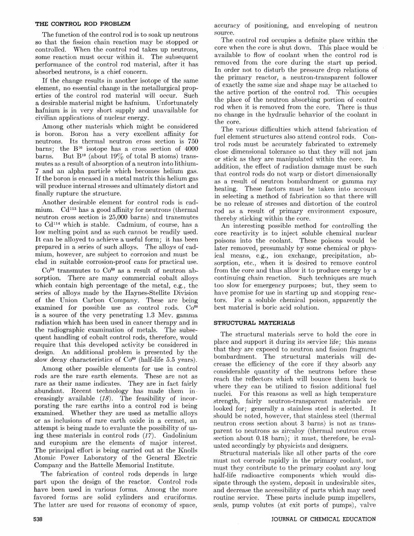
9"9PENI,ON OF i U O * Y U . &NO URLNIUM-OXIDE SLURRY IN WaTLR
1 I
REMOVAL OF i85S1ON PRODUCTS
Single-Region Aqueous Slurry Breeder Reactor
side. Gas-cooled reactors have been used in England and are being considered for the United States. In May 1956 the Calder Hall Reactor was put in opera- tion in the United Kingdom. This reactor uses carbon dioxide as a coolant. The use of inert gases permits higher temperature operation of clad fuel elements.
The use of gas as a coolant (heat transfer medium) has the drawback that a large amount of the power generated by the reactor must be diverted to pump- ing the gas around the system. Air is not a partic- ularly good choice for the coolant because of nuclear reactions and the damaging corrosive effect of hot air on most economical materials of construction. Radioactive W6 with a half-life of 7.35 seconds is formed in-pile from 016. This isotope of nitrogen decays by emission of strong beta and gamma radia- tion. Hydrogen, a desirable coolant from considera- tions of heat transfer and nuclear characteristics, is dangerous because of the hazard of explosion in the event of leakage and contact with a source of oxygen. Helium is almost as desirable as hydrogen thermody- namically; it is of course a comparatively expensive material. The use of helium mould require a leak- proof system to avoid costly replacement of the coolant.
The effect of the choice of the coolant on the other components of the primary system must he constantly kept in mind. The coolant is the universal bath to which all primary system components are exposed continuously. For this reason the selection of the coolant is very critical. Recent studies in liquid metals have indicated that, although sodium-potas-
VOLUME 35, NO. 10, NOVEMBER, 1958

sium alloy has the important advantage of melting a t room temperature (lS°C.), good thermal conductivity, and high heat capacity, bismuth, particularly in the form of its eutectic alloy with lead, has other advan- tages. The bismuth-lead alloy is presently being explored a t the Brookhaven National Laboratory (96). Bismuth has a capture cross section of only 0.015 barn with a melting point of 271°C.; the bismuth-lead eutectic melts at 125'C. and has a capture cross section of 0.17 barn. This compares with a tenfold neutron cross section value for the sodium-potassium alloy. Further, the accidental contact of hot bismuth with water is less fraught with danger than a simiiar contact of sodium potassium alloy. These advantages may possibly turn out to far outweigh the advantages of sodium-potassium alloy.
The composition of the primary coolant in pressur- ized water reactors gets very considerable attention. Undesirable ions may be removed by ion exchange methods or by absorption. Solid or semisolid cor- rosion products may be removed by suitable filters, absorption on a solid surface, or coated out on ion-ex- changer beds. The primary coolant can be expected to contain transport corrosion products plus the prod- uct of leaching of fuel elements where an accidental break in cladding occurs. These components ("crud") are radioactive and tend to deposit on surfaces remote from the point of origin (97). This condition de- creases accessibility of the system to routine mainte- nance. I t is imperative to keep the level of these com- ponents low through suitable crud traps.
LITERATURE CITED
(1) GLASSTONE, SAMUEL, "Sourcebook on Atomic Energy," D. Van Nostrand Co., Inc., New York, 1950, pp. 348, 632 ff.
(2) S ~ N , C. R., AND D. 0. LEESER, Nudemica, 12, No. 9, 8 (1954).
(3) CALKINS. V. P., Nucleonics, 12, NO. 9, 9 (1954). (4) "Nuclear Fuels," edited by Gurinsky-Dienes, D. Van
Nostrand Co., Inc., Princeton, New Jersey, 1956, pp. 243
ff. (based on HOWE, J. P., "The Metallurgy of Reactor Fuels," Geneva Paper No. 825).
(5) Nucleonies, 14, No. 2, 45 (1956). (6) LANE, J . A,, Nucleonics, 12, No. 6,51(1954). (7) FRYE, J., AND W. GREGG, Metal Progress, Sept., 1956, pp. 92
A ... (8) DEUTSCH, R. W., Nucleonics, 14, No. 9, 89 (1956). (9) COHEN, P., private communication.
(10) "Lange's Handbook of Chemistry," 8th ed., Handbook Pub- lishers, Ino., Sandusky, Ohio, 1955, pp. 96 ff.
(11) MCCORD, A. T., More ZT Facts, 1, NO. 2, 3 (1957): The Carborundum Metals Co., Akron, New York.
(12) "Progress in Nuclear Energy, Vol. 5: Metallurgy and Fuels," edited by Finneston-Howe, McGraw-Hill Book Co., Inc., New Yark, 1956, pp. 318 ff.
(13) SGTTON, C. R., AND D. LEESER, Nucleonics, 12, No. 9, 8 (1954); WILSON, J., AND D. S. BILLINGTON, Engineering Council Nuclear Congress, Cleveland, Ohio (Dec., 1955); WILSON, J., AND C. BERGGREN, Pmc. A.S.T.M., in press.
(14) BILLINGTON, D. S., ET AL., Nucleonics, 14, No. 9, pp. 54 ff. 1 1 4 6 ) ,-""",.
(15) DRALEY, J., AND W. E. RUTAER. Cowosion, Sevt.. 1956, D. . - . . . 31; 0&.,'1956, p. 20.
(16) KIEFFER, W. F., J. CHEM. EDUC., 31, 488 (1954). (17) ANDERSON. W. K.. AND D. DUNNING. Pmer NO. 57-NESC- , .
66, 2nd Nuclear Engineering and Science Conference, Philadelphia, Pa., March 11-14, 1957.
(18) Chem. Eno. News. 35. No. 40. DD. 78. 79 (1957). . . ... , . . i l g j See also review article by woo mu^^, O. J., ET AL., NU-
cleonics, 11, No. 6, 27 (1953). (20) CALKINS, V. P., nucleonic^, 12, NO. 9, 9 (1954); COLICH-
m ~ , E. L., AND R. H. J . GERCKE, Nueleonics, 14, No. 7, 50 11956).
(21) FRET~ND, d., Nucleonics, 14, No. 8, 62 (1956). (22) PARKINS, W. E., Chern. Eng., 64, 253 (1957). (23) WELINSKY, I. H. P., AND D. COHEN, C h a . Eng. Prog., 52,
XRR (1 P5RI --- \----,-
(24) GLASSTONE, S., Ref. (l), p. 295. (25) DWYER, 0. E., Nucleonics, 12, No. 7,30 (1954); GRAY, I. L.,
R. L. NEAL, AND B. G. VOORHEES, Nucleonics, 14, No. 10, 34 (1956); COTTRELL, W. B., AND L. A. MANN, Nucleon- ics, 12, No. 12, 22 (1954).
(26) DWYER, 0. E., Ref. ($6); TEITEL, R. J., D. GURINSKY, AND
J. S. BRYNER, Nucleonics, 12, NO. 7, 14 (1954); GURINSKY, D., ET AL., Nucleonics, 12, NO. 7, 40 (1954).
(27) LYON, W. S., AND 9. A. REYNOLDS, Nucleonics, 13, NO. 10, 60 (1955).
JOURNAL O F CHEMICAL EDUCATION