Embed Size (px)
Citation preview

© 2014 IAU, Arak Branch. All rights reserved.
Journal of Solid Mechanics Vol. 6, No. 2 (2014) pp. 208-228
Numerical Simulation of Semi-Elliptical Axial Crack in Pipe Bend Using XFEM
K. Sharma1, I.V. Singh2,*, B.K. Mishra2, S.K. Maurya2 1Reactor Structures Section, Reactor Safety Division, BARC, Mumbai, India 2Department of Mechanical and Industrial Engineering, Indian Institute of Technology Roorkee , UK, India
Received 6 March 2014; accepted 4 May 2014
ABSTRACT
In this work, XFEM is employed to obtain the stress intensity factors (SIFs) of a semi elliptical part through thickness axial crack. In XFEM, additional functions are employed to enrich the displacement approximation using partition of unity approach. Level set functions are approximated using higher order shape functions in the crack front elements to ensure the accurate modeling of the crack. The axial crack is placed either on the inner or the outer surface in an internally pressurized pipe bend. The SIFs are extracted from XFEM solution by domain type interaction integral approach for a wide range of geometry parameters like bend radius ratio, cross sectional radius ratio and relative crack length. The results obtained by XFEM approach are compared with those obtained by FEM. These simulations show that the orientation and type of crack in pipe bend has a significant effect on the SIF.
© 2014 IAU, Arak Branch.All rights reserved.
Keywords: Elliptical cracks; Pipe bend; SIFs; XFEM
1 INTRODUCTION
RACKS are found in all machine components at micro or macro level. The crack/defect assessment methods are needed for the safe operation of plant components. Pipe bend is important part of pipeline systems in the
chemical and nuclear industry. It has more geometric variables involved than straight pipe. These are generally known to be the most economical means of changing directions while providing flexibility, and end reactions to systems within the allowable limits.
A number of analyses exist for straight thick-walled cylinders with semi-elliptical cracks under internal pressure [1-7]. Thick-walled curved tubes and elbows are also presented but the studies on cracked elbow and tubing are very limited. Chattopadhyay et al. [8-9], Yahiaoui et al. [10], Saxena and Ramakrishnan [11] performed the studies on through thickness circumferential and longitudinal cracks under bending loads. Only few standard shape crack problems have the closed form analytical solutions. Therefore, the numerical methods are the only choice left to analyze real life crack problems. Although, numerical methods can simulate these problems but the accurate and efficient simulation of these cracks still remains a most challenging tasks for the fracture mechanics community. It is known that during fatigue loading, an initial crack of semi-elliptical shape grows up to the critical size. Hence, the analysis of semi-elliptical crack in pipe is quite important from the failure point of view. Therefore, the semi-elliptical crack placed either on the outer or the inner surface of the pipe bend has been considered in the present work.
______ * Corresponding author. Tel.: +91 1332 285888; Fax: +91 1332 285665. E-mail address: [email protected] (I.V. Singh).
C

209 Sharma et al.
© 2014 IAU, Arak Branch
To simulate cracked structures/components, a number of methods such as finite element method (FEM) [12-16], boundary element method (BEM) [17-18], and meshfree methods [19-20] have been developed over the years. In FEM, the geometry is normally modeled by an adequate mesh as it requires that a crack must coincide with the edges of the finite elements i.e. a conformal mesh is required apart from the requirement of special elements to handle crack tip asymptotic stress fields. The finite element simulation of a part through propagating crack in pipe and pipe bend becomes even more difficult, time consuming and inaccurate due to conformal mesh requirement and mapping the variables from previous step to next step. To get rid of these issues, extended finite element method (XFEM) has been developed as an alternative to solve the problems of 3-D cracks. In XFEM, these discontinuities are modeled by adding enrichment functions in the finite element displacement approximation through partition of unity [21-23]. These enrichment functions are obtained from the theoretical background of the problem. Many enrichment functions have been proposed by the researchers [24-25] to model the cracks. Primarily two enrichment functions are required to model a crack in XFEM: first one is discontinuous on the crack surface while the second one is asymptotic at the crack front. Thus, XFEM provides the precise modeling of the cracks. Sukumar et al. [26] presented 3-D XFEM formulations for the modeling of mode-I crack problems, and showed that the XFEM results are compared well with the benchmark solutions.
In this work, not only the XFEM has been extended further for the simulation of 3-D cracks in pipe bend but also a non-iterative solution scheme has been adopted to define the geometry of the crack surface. A vector level set approach [27-28] is utilized for analyzing the 3-D cracks. Domain based interaction integral approach is adopted for mixed mode stress intensity factors [29]. The XFEM results are obtained for a wide range of pipe bend parameters like bend radius ratio, radius ratio and relative crack length.
2 XFEM METHODOLOGY
Three-dimensional XFEM formulation for a crack is described in the following sub-sections:
2.1 Governing equations
The governing equations of elasto-statics with internal discontinuities are briefly reviewed and an associated weak form is given [23]. Consider a domain, bounded by the boundary is partitioned into three sets: u , t and c as
shown in Fig. 1. Displacements are prescribed on u , tractions are prescribed on t . All c surfaces are assumed
to be traction free. The equilibrium conditions and boundary conditions for this problem are given as:
. 0b in (1)
.n t on t (1a)
. 0n on c (1b)
where, is the Cauchy stress tensor, u is the displacement field, b is the body force per unit volume and n
is the
unit outward normal. It is assumed that displacements remain small and the kinematics equations consist of the strain-displacement relation:
( ) su u (2)
where, s is the symmetric part of the gradient operator. The boundary conditions
u u on u (3)
The constitutive relation for the elastic material under consideration is given by Hook's law
D (4)

Numerical Simulation of Semi-Elliptical Axial Crack in Pipe Bend Using XFEM 210
© 2014 IAU, Arak Branch
xe
ze
ye
t
cr
crcr
u
where, D is the Hooke’s tensor.
Fig. 1 Domain with a discontinuity.
2.2 XFEM formulation
The XFEM eliminates the burden associated with the conformal mesh requirement for the problems involving cracks. In XFEM, domain is divided into two distinct parts i.e. enriching the finite element approximation by additional functions to model the internal boundaries and mesh generation for the domain.
According to the concept of partition of unity, the standard approximation is enriched with additional functions. The enriched displacement approximation can be written in general form for 3-D crack modeling [32]:
4
1 1
( ) ( ) ( ) ( ) ( ) ( )
rA
nh
j j j j j jj
j nj n
N H H
u x x u x x a x x b
(5)
where, n is the set nodes in the mesh, rn is the set of those nodes whose shape function is completely cut by the
crack surface, and An is the set of those nodes whose shape function support is partially cut by the crack front, ju
is the nodal displacement vector associated with the continuous part of the finite element solution, ja is the
additional degree of freedom vector associated with the Heaviside function, ( )H X , jb is the additional degree of
freedom vector associated with asymptotic functions, ( )X ; ( )H X is the Heaviside function defined for those
elements which are completely cut by the crack surface, and ( )X are the asymptotic functions defined for those
elements which are partially cut by the crack front. To model the radial as well as the angular behavior of asymptotic crack-tip stress fields, the following four enrichment functions are used [23]:
1 2 3 4 cos , sin , cos sin , sin sin2 2 2 2
( ) , , , r r r r
x
(6)
The potential energy function for a solid mechanics problem can be written as:
1
( ) ( ) : : ( ) . .2
tΓ
d d d
u ε u C ε u b u t u
(7)
By substituting the trial and test functions from Eq. (5) in the above equation and using the arbitrariness of the
nodal variables, the following set of discrete equations are obtained

211 Sharma et al.
© 2014 IAU, Arak Branch
d fK (8)
where, K is the global stiffness matrix, d is the vector of nodal unknown variables, and f is external force vector.
The elemental K and f vectors are given as:
1 2 3 4eT
u a b b b bi i i i i if f f f f f f (9)
uu ua ubij ij ij
e au aa abij ij ij ij
bu ba bbij ij ij
K
K K Κ
K K K
K K K
(10)
where,
, , ,e
T
ij i j d u a b
K Β C Β (11)
et
ui i iΝ d Ν d
f t b (12)
( ) ( ) ( ) ( )e
t
ai i i i iΝ H H d Ν H H d
f x x t x x b (13)
( ) ( ) ( ) ( )e
t
bαi i i i iΝ d Ν d
f x x t x x b (14)
Using shifted enrichment [32], uiΒ , a
iΒ and biΒ are defined as:
,
,
,
, ,
, ,
, ,
0 0
0 0
0 0
0
0
0
i x
i y
i zui
i z i y
i z i x
i y i x
N
N
N N
N N
N N
N
Β
(15)
,
,
,
, ,
, ,
, ,
( ) ( ) 0 0
0 ( ) ( ) 0
0 0 ( ) ( )
0 ( ) ( ) ( ) ( )
( ) ( ) 0 ( ) ( )
( ) ( ) ( ) ( ) 0
i i x
i i y
i i zai
i i i iz y
i i i iz x
i i i iy x
H H
N H H
N H H
N H H N H H
N H H N H H
N H H N H H
N
x x
x x
x x
x x x x
x x x x
x x x x
Β
(16)
1 2 3 4b b b b bi i i i i Β Β Β Β Β (17)

Numerical Simulation of Semi-Elliptical Axial Crack in Pipe Bend Using XFEM 212
© 2014 IAU, Arak Branch
,
,
,
, ,
, ,
, ,
( ) ( ) 0 0
0 ( ) ( ) 0
0 0 ( ) ( )
0 ( ) ( ) ( ) ( )
( ) (( ) 0 ( ) ( )
( ) ( ) ( ) ( ) 0
i i x
i i y
i i zbi
i i i iz y
i i i iz x
i i i iy x
N
N
N
N N
N N
N N
x x
x x
x xΒ
x x x x
x x x x
x x x x
(18)
2.3 Vector level sets for a crack
In vector level set, a crack is defined by two vector functions [26, 28, 30]. These functions are calculated at nodes. Finite element interpolation functions are approximated using these functions. Vector level set is evaluated only for those elements which have their mean centre lying in a narrow band of the crack surface for improving the computational efficiency. Many geometric operations are performed on the data for updating the vector level set. As a result, this crack is entirely described by the nodal data without the need of any physical representation. Thus, the computation of the level set becomes more efficient. The crack geometry is approximated using quadratic twenty node hexahedral elements to improve the accuracy, and the problem domain is approximated by using eight node linear solid elements.
Level set function, ( ) x is a signed distance function, which can be computed from ( )f x by the following
formula 2( ) ( ) . ( )H x f x ξ f x , where ( )f x is the vector between a point x and its projection on the crack
surface ( cr ), and is directed from x to the crack surface, i.e. ( ) f f x x x where fx is the closest point
projection of x on the crack surface ( cr ) and ( )H x is the Heaviside function which takes +1 above the crack
surface and -1 below the crack surface. The second level set function is a signed distance function with respect to the crack front, and is computed using the following formula 1( ) . ( ) x ξ f x . A crack surface with the finite
elements is represented by
1
( ) ( ) ( )n
approx i ii
N
x x x
(19)
1
( ) ( )n
approx i ii
N
x x x
(20)
The criterion for the finding whether an element belongs to crack front or crack surface, is given as: For crack front elements: ( ) 0approx x and ( ) 0approx x
For crack surface elements: ( ) 0approx x and ( ) 0approx x .
The enrichment procedure in 3-D is more complicated as compared to 2-D but the basic principle remains the same. In general, it is quite tedious to find nearest point on a curve from an arbitrary point. Therefore, an iterative procedure was adopted in literature to define the geometry of the crack surface [28, 30].
2.4 Numerical integration
In case of enriched element, numerical integration needs special treatment due to the presence of discontinuity in the integrand. Integration of enriched elements is achieved by dividing them into several tetrahedrons above and below the surface. To evaluate this, intersection point of element edges and crack front with element surfaces is calculated [33]. Integration of enriched elements generally requires higher order Gauss quadrature. In the present work, three, seven and two points Gauss quadrature scheme is used in crack surface, crack front and rest of the elements, respectively.

213 Sharma et al.
© 2014 IAU, Arak Branch
2.5 Interaction integral
Domain based interaction integral approach has been adopted for the evaluation of individual stress intensity factors
,I II IIIK K and K under mixed-mode loading. Fig. 2 shows the domain for J-integral. Virtual domain extension
approach is used for the evaluation of J-integral in 3-D [34]. In this approach, volume integral over the domain surrounding the crack front is expressed in terms of a crack front contour integral. Individual SIFs are extracted from XFEM solution by superimposing two states of the stress. One state (auxiliary state) is assumed to be known while other one is the actual state. The SIF of the known auxiliary state is taken as one for the mode which is being evaluated while the SIFs of remaining two modes in auxiliary states are assigned zero values. Thus, the actual SIF of that mode which is assigned one value is in auxiliary state, remains unknown, and can be evaluated by solving an interaction integral [27, 34-37]]. The same procedure is adopted for the other modes also. Now, the path independent J-integral for a homogeneous cracked body is given as:
11
ij ij j
u
xJ W n dΓ
(21)
J-integral is not evaluated over the crack surface since it is traction free. Fig. 2 shows the surface contour integral which is virtually extended along the crack front. Green divergence theorem is used to convert a closed surface integral into the volume integral by taking its gradient as discussed by Pathak et al. [30]. J-integral is equal to the energy release rate for elastic materials. For a mixed-mode case, it is given as:
2 2 21 1
' 2I II IIIJ G K K KE
(22)
where, '21
EE
and
2 1
E
The stress intensity factors IK , IIK and IIIK are computed in the direction of fatigue crack growth. Now
consider two independent equilibrium state of a cracked body. State 1 is taken as actual state for the given boundary conditions while state 2 is an auxiliary state. The J -integral for two superposed states is provided as:
1 2
1 21
1
i itot totj ij ij j
u uJ W n d
x
(23)
where, 1 2 1 21
2tot
ij ij ij ijW
Eq. (23) can be expanded, and rearranged to yield
1 2 1,2totJ J J M (24)
In Eq. (24), 1J , 2J are the J-integral for states 1 and 2 and 1,2M is the interaction integral for two
equilibrium states.
2
1,22 1 1
2aux aux aux
I I II II III IIIM t K K K K K KE
(25)

Numerical Simulation of Semi-Elliptical Axial Crack in Pipe Bend Using XFEM 214
© 2014 IAU, Arak Branch
Fig. 2 Hollow cuboidal domain around penny crack.
3 NUMERICAL RESULTS AND DISCUSSION
In the present work, the stress intensity factors for a cracked pipe bend are evaluated under internal pressure. An axial semi-elliptical crack is placed either at extrados or at the intrados. A schematic of the pipe bend is shown in Fig. 3. Pipe bend has been analyzed for different values of bend radius ratio (R*=R/R1), cross-sectional radius ratio (k=R2/R1) and relative crack length (a/t). The extent of the pipe bend is taken as 90 degree. In this study, the following values of various parameters are considered: bend radius ratio, R* = R/R1 = 5, 6.25, 7.5 and 8.75, cross-sectional radius ratio, k = R2/R1 = 1.25, 1.375, 1.5 and 1.625.
The relative crack depth (a/t), where t = (R2 - R1) is the wall thickness, and values of a/t is taken as 0.5 and 0.75. The crack shape aspect ratio is taken as b/a = 1.6. A tangential straight pipe section (with same radius ratio, k) of length 3R2 is added at each end of the elbow/pipe bend along with displacement constraints to reduce the end effects.
A number of cases of pipe bend with an axial elliptical cracks lying at the intrados as well as at the extrados have been taken for the simulation. The values of stress intensity factors are evaluated at the tip of minor axis, and are compared with the finite element solutions. An extrinsic enrichment technique based on partition of unity has been implemented to capture the discontinuity due to the presence of cracks. To model the curved crack front accurately, it has been divided into one hundred splined-curve parts for all the problems under consideration. The values of SIFs are evaluated for each location of the axial elliptical crack by varying the bend radius ratio, radius ratio and relative crack depth. The results obtained by XFEM are compared with FEM solution obtained in ANSYS using a mesh of 5x100x18 nodes.
Fig. 3 Schematic of pipe bend.
Evaluation point
b
b
Ve
R
R
R

215 Sharma et al.
© 2014 IAU, Arak Branch
Case 1: Axial part through crack at extrados external
Pipe bend having an axial semi-elliptical crack lying at the outer surface of the bend has been simulated by proposed XFEM approach. The geometry of the pipe bend along with the crack and boundary conditions is shown in Fig. 4. The material of the bend is assumed to be homogeneous and isotropic with 2200 000 N/mmE and Poisson ratio
0.3. The minor and major axis of semi-elliptical crack are taken as 0.015 m and 0.024 m. The pipe bend is subjected to an internal pressure of 10 MPa. An eight node linear brick element has been used for meshing the geometry. The dimensions of contour integral are taken as Ve = 0.004 m and b = 0.004 m. A regular mesh of 5x100x18 nodes is used in all simulations.
The variation of SIF with pipe bend radius ratio (R*) is shown in Fig. 5 for four different values of cross-sectional radius ratio (k). The relative crack depth (a/t) and inner radius of the pipe bend (R1) are kept constant for these simulations. Figs. 5(a), 5(b), 5(c) and 5(d) show the variation of SIF with R* for k values of 1.25, 1.375, 1.5 and 1.625, respectively. From these figures, it can be seen that the SIF values marginally increases with the increase in R* from 5.0 to 8.75. Fig. 6 depicts the variation of stress intensity factor with respect to R* for four different values of k. The relative crack depth (a/t) is kept constant and is taken as 0.5. The inner radius of the pipe bend (R1) is also kept constant at 0.08 m. Figs. 6(a), 6(b), 6(c) and 6(d) present the variation of SIF with R* for the k values of 1.25, 1.375, 1.5 and 1.625, respectively. It can be concluded that the SIF values marginally increases with the increase in bend radius ratio from 5.0 to 8.75. It is also observed that the large relative crack depth results in large SIF values, if rests of pipe bend parameters kept constant.
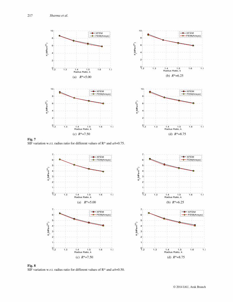
The variation of SIF with k is shown in Fig.7 for four different values of R*. The relative crack depth (a/t) is kept constant, and is taken as 0.75. The inner radius of the pipe bend (R1) is kept constant. Figs. 7(a), 7(b), 7(c) and 7(d ) show the variation of SIF with k for R* equal to 5.0, 6.25, 7.5 and 8.75, respectively. From these figures, it can be seen that the SIF values decreases with the increase in k from 1.25 to 1.625. Fig.8 depicts the variation of stress intensity factor with k for four different values of R*. The relative crack depth (a/t) is kept constant, and is taken as 0.5. The inner radius of the pipe bend (R1) is kept constant for these simulations. The variation of SIF with radius ratio is shown in Figs. 8(a), 8(b), 8(c) and 8(d) for R* of 5.00, 6.25, 7.5 and 8.75, respectively. It is observed that the SIF values decreases with the increase in R* from 1.25 to 1.625. It is also noticed that the large relative crack depth results in high SIF values, if the rest of pipe bend parameters are kept constant. From the SIF, it is observed that the numerical solution obtained by XFEM is found quite close to the solution obtained using Ansys (FEM). It is also found that the relatively large crack depth results in large SIFs, if the rest of parameters are kept constant. It is also found that influence of cross sectional radius ratio (k) is more on SIFs in comparison to bend radius ratio (R*).
Fig. 4 Pipe Bend crack at extrados external location.
d
D
d
D
R
Angle

Numerical Simulation of Semi-Elliptical Axial Crack in Pipe Bend Using XFEM 216
© 2014 IAU, Arak Branch
5 6 7 8 90
2
4
6
8
10
12
KI (
MP
a-m
1/2 )
Bend Radius Ratio, R*
XFEMFEM(Ansys)
5 6 7 8 90
1
2
3
4
5
6
7
8
KI (
MPa-m
1/2 )
Bend Radius Ratio, R*
XFEMFEM(Ansys)
(a) k =1.25
Fig. 5 SIF variation with bend radius ratio (R*) for different values of k and a/t=0.75.
(b) k =1.375
Fig. 6 SIF variation with bend radius ratio for different values of k and a/t=0.50.
5 6 7 8 90
2
4
6
8
10
12
KI (
MP
a-m
1/2 )
Bend Radius Ratio, R*
XFEMFEM(Ansys)
(b) k =1.375
(c) k =1.50
5 6 7 8 90
2
4
6
8
10
12
KI (
MP
a-m
1/2 )
Bend Radius Ratio, R*
XFEMFEM(Ansys)
(d) k =1.625
5 6 7 8 90
2
4
6
8
10
12
KI (
MPa-m
1/2 )
Bend Radius Ratio, R*
XFEMFEM(Ansys)
5 6 7 8 90
1
2
3
4
5
6
7
8
KI (
MP
a-m
1/2 )
Bend Radius Ratio, R*
XFEMFEM(Ansys)
(a) k =1.25
(c) k =1.25
5 6 7 8 90
1
2
3
4
5
6
7
8
KI (
MP
a-m
1/2 )
Bend Radius Ratio, R*
XFEMFEM(Ansys)
(d) k =1.25
5 6 7 8 90
1
2
3
4
5
6
7
8
KI (
MPa-m
1/2 )
Bend Radius Ratio, R*
XFEMFEM(Ansys)
217 Sharma et al.
© 2014 IAU, Arak Branch
Fig. 7 SIF variation w.r.t. radius ratio for different values of R* and a/t=0.75.
Fig. 8 SIF variation w.r.t. radius ratio for different values of R* and a/t=0.50.
1.2 1.3 1.4 1.5 1.6 1.70
2
4
6
8
10
KI (
MP
a-m
1/2 )
Radius Ratio, k
XFEMFEM(Ansys)
(a) R*=5.00
1.2 1.3 1.4 1.5 1.6 1.70
2
4
6
8
10
KI (
MPa-m
1/2 )
Radius Ratio, k
XFEMFEM(Ansys)
(b) R*=6.25
1.2 1.3 1.4 1.5 1.6 1.70
2
4
6
8
10
KI (
MPa-m
1/2 )
Radius Ratio, k
XFEMFEM(Ansys)
(c) R*=7.50 (d) R*=8.75
1.2 1.3 1.4 1.5 1.6 1.70
2
4
6
8
10
KI (
MPa-m
1/2 )
Radius Ratio, k
XFEMFEM(Ansys)
1.2 1.3 1.4 1.5 1.6 1.70
1
2
3
4
5
6
7
KI (
MP
a-m
1/2 )
Radius Ratio, k
XFEMFEM(Ansys)
(a) R*=5.00 (b) R*=6.25
1.2 1.3 1.4 1.5 1.6 1.70
1
2
3
4
5
6
7
KI (
MP
a-m
1/2 )
Radius Ratio, k
XFEMFEM(Ansys)
(c) R*=7.50
1.2 1.3 1.4 1.5 1.6 1.70
1
2
3
4
5
6
7
KI (
MP
a-m
1/2 )
Radius Ratio, k
XFEMFEM(Ansys)
(d) R*=8.75
1.2 1.3 1.4 1.5 1.6 1.70
1
2
3
4
5
6
7
KI (
MPa-m
1/2 )
Radius Ratio, k
XFEMFEM(Ansys)

Numerical Simulation of Semi-Elliptical Axial Crack in Pipe Bend Using XFEM 218
© 2014 IAU, Arak Branch
d
D
d
D
R
Angle
Case II: Axial part through crack at extrados internal
In the present case, pipe bend dimensions, crack length, loading, boundary conditions, material properties and meshing remain the same as in case-I. An axial semi-elliptical crack lying at inner surface has been simulated by XFEM. The geometry of the pipe bend along with the crack and boundary conditions is shown in Fig.9. The dimensions of interaction integral contour are taken as Ve = 0.004 m and b = 0.004 m. A regular mesh of 5x100x18 nodes has been used in these simulations.
The variation of SIF with pipe bend radius ratio (R*) is shown in Fig.10 for four different values of cross-sectional radius ratio (k). The relative crack depth (a/t) is kept constant and is taken as 0.75. The inner radius of the pipe bend (R1) is also kept constant at 0.08 m. Figs. 10(a), 10(b), 10(c) and 10(d) show the variation of SIF with R* for four k values of 1.25, 1.375, 1.5 and 1.625, respectively. Fig. 11 depicts the variation of stress intensity factor with respect to R* for four different values of k. The value of a/t is kept constant and is taken as 0.5. Figs.11(a), 11(b), 11(c) and 11(d) present the variation of SIF with R* for four values k of 1.25, 1.375, 1.50 and 1.625, respectively. It can be concluded that the SIF values marginally increases with increase in bend radius ratio from 5.0 to 8.75. The variation of SIF with radius ratio (k) is shown in Fig. 12 for four different values of bend radius ratio (R*). The relative crack depth (a/t) is taken as 0.75 for these simulations. The inner radius of the pipe bend (R1) is kept constant at 0.08 m. Figs. 12(a), 12(b), 12(c) and 12(d) show the variation of SIF with k for R* equal to 5.0, 6.25, 7.5 and 8.75, respectively. From these figures, it can be seen that the SIF values decreases with the increase in k from 1.25 to 1.625.
The variation of stress intensity factor with respect to k for four different values of R* is shown in Fig.13. The value of a/t is kept constant at 0.5. Figs. 13(a), 13(b), 13(c) and 13(d) present the variation of SIF with k for four values of R* equal to 5.00, 6.25, 7.5 and 8.75, respectively. It can be concluded that the SIF values decreases with increase in bend radius ratio from 1.25 to 1.625. From the SIF plots, it is noticed that higher crack depth results in higher the SIFs, if the rest of parameters are kept constant. It was also found that influence of cross sectional radius ratio is more in comparison to bend radius ratio. It is also found that values of SIF are higher for externally exposed crack in comparison to internally exposed crack. Moreover, it is also observed that the numerical results obtained by XFEM are found in good agreement with those obtained by FEM.
Fig. 9 Pipe Bend crack at extrados internal location.

219 Sharma et al.
© 2014 IAU, Arak Branch
Fig. 10 SIF variation with bend radius ratio (R*) for different values of k and a/t=0.75.
Fig. 11 SIF variation with bend radius ratio (R*) for different values of k and a/t=0.50.
(a) k =1.25
5 6 7 8 90
2
4
6
8
10
KI (
MPa-m
1/2 )
Bend Radius Ratio, R*
XFEMFEM(Ansys)
5 6 7 8 90
2
4
6
8
10
KI (
MPa-m
1/2 )
Bend Radius Ratio, R*
XFEMFEM(Ansys)
(b) k =1.375
5 6 7 8 90
2
4
6
8
10
KI (
MP
a-m
1/2 )
Bend Radius Ratio, R*
XFEMFEM(Ansys)
(c) k =1.50
5 6 7 8 90
2
4
6
8
10
KI (
MP
a-m
1/2 )
Bend Radius Ratio, R*
XFEMFEM(Ansys)
(d) k =1.625
(a) k =1.25
5 6 7 8 90
1
2
3
4
5
6
7
8
KI (
MPa-m
1/2 )
Bend Radius Ratio, R*
XFEMFEM(Ansys)
(b) k =1.375
5 6 7 8 90
1
2
3
4
5
6
7
8
KI (M
Pa-m
1/2 )
Bend Radius Ratio, R*
XFEMFEM(Ansys)
(c) k =1.50
5 6 7 8 90
1
2
3
4
5
6
7
8
KI (
MP
a-m
1/2 )
Bend Radius Ratio, R*
XFEMFEM(Ansys)
(d) k=1.625
5 6 7 8 90
1
2
3
4
5
6
7
8
KI (
MPa-m
1/2 )
Bend Radius Ratio, R*
XFEMFEM(Ansys)

Numerical Simulation of Semi-Elliptical Axial Crack in Pipe Bend Using XFEM 220
© 2014 IAU, Arak Branch
Fig. 12 SIF variation w.r.t. radius ratio for different values of R* and a/t=0.75.
Fig. 13 SIF variation w.r.t. radius ratio for different values of R* and a/t=0.50.
1.2 1.3 1.4 1.5 1.6 1.70
1
2
3
4
5
6
7
8
9
KI (
MPa-m
1/2 )
Radius Ratio,k
XFEMFEM(Ansys)
(a) R*=5.00 (b) R*=6.25
1.2 1.3 1.4 1.5 1.6 1.70
1
2
3
4
5
6
7
8
9
KI (M
Pa-m
1/2 )
Radius Ratio,k
XFEMFEM(Ansys)
(c) R*=7.50
1.2 1.3 1.4 1.5 1.6 1.70
1
2
3
4
5
6
7
8
9
KI (
MPa-m
1/2 )
Radius Ratio,k
XFEMFEM(Ansys)
(d) R*=8.75
1.2 1.3 1.4 1.5 1.6 1.70
1
2
3
4
5
6
7
8
9
KI (
MPa-m
1/2 )
Radius Ratio,k
XFEMFEM(Ansys)
(a) R*=5.00
1.2 1.3 1.4 1.5 1.6 1.70
1
2
3
4
5
6
KI (M
Pa-m
1/2 )
Radius Ratio,k
XFEMFEM(Ansys)
(b) R*=6.25
1.2 1.3 1.4 1.5 1.6 1.70
1
2
3
4
5
6
KI (
MPa-m
1/2 )
Radius Ratio,k
XFEMFEM(Ansys)
(c) R*=7.50
1.2 1.3 1.4 1.5 1.6 1.70
1
2
3
4
5
6
KI (M
Pa-m
1/2 )
Radius Ratio,k
XFEMFEM(Ansys)
(d) R*=8.75
1.2 1.3 1.4 1.5 1.6 1.70
1
2
3
4
5
6
KI (M
Pa-m
1/2 )
Radius Ratio,k
XFEMFEM(Ansys)

221 Sharma et al.
© 2014 IAU, Arak Branch
Case III: Axial part through crack at intrados external
In the present case, pipe bend dimensions, crack length, loading, boundary conditions, material properties and meshing remain same as in case-I. An axial semi-elliptical crack lying at the outer surface has been simulated by XFEM. The geometry of the pipe bend along with the crack and boundary conditions is shown in Fig.14. The contour integral dimensions are taken as Ve = 0.004 m and b = 0.004 m. A regular mesh of 5x100x18 nodes is used for these simulations.
The variation of SIF with pipe bend radius ratio (R*) is shown in Fig.15 for four different values of cross-sectional radius ratio (k). The relative crack depth (a/t) is kept constant and is taken as 0.75. The inner radius of the pipe bend (R1) is also kept constant at 0.08 m for these simulations. Figs. 15(a), 15(b), 15(c) and 15(d) show the variation of SIF with bend radius ratio for the cross sectional radius ratio of 1.25, 1.375, 1.5 and 1.625, respectively. From these figures, it can be seen that the SIF values marginally decreases with the increase in bend radius ratio. Fig.16 depicts the variation of stress intensity factor with R* for four different values of k. The relative crack depth (a/t) is kept constant, and is taken as 0.5. The variation of SIF with R* is shown in Figs. 16(a), 16(b), 16(c) and 16(d) for k equal to 1.25, 1.375, 1.5 and 1.625, respectively. It can be concluded that the SIF values marginally decreases with the increase in bend radius ratio from 5.0 to 8.75. The variation of SIF with radius ratio (k) is shown in Fig. 17 for four different values of bend radius ratio (R*). The relative crack depth (a/t) is kept constant, and is taken as 0.75. The inner radius of the pipe bend (R1) is kept constant. Figs. 17(a), 17(b), 17(c) and 17(d) show the variation of SIF with k for R* equal to 5.00, 6.25, 7.5 and 8.75, respectively. From these figures, it can be seen that the SIF values decreases with the increase in radius ratio.
The variation of stress intensity factor (KI) with radius ratio is shown in Fig. 18 for four different values of bend radius. The relative crack depth (a/t) is kept constant and is taken as 0.5. The inner radius of the pipe bend (R1) is also kept constant for these simulations. Figs. 18(a), 18(b), 18(c) and 18(d) present the variation of SIF with radius ratio for the bend radius ratio of 5.00, 6.25, 7.5 and 8.75, respectively. It is found that the SIF values decreases with the increase in bend radius ratio. From above plots, it is observed that the numerical solution obtained by XFEM approach is quite close to the solution obtained using FEM (Ansys). It is also found that relatively higher crack depth results in higher SIFs if the rest of parameters are kept constant. It was also found that influence of cross sectional radius ratio is more in comparison to bend radius ratio.
Fig. 14 Pipe Bend crack at intrados external.
d
D
d
D
R
Angle

Numerical Simulation of Semi-Elliptical Axial Crack in Pipe Bend Using XFEM 222
© 2014 IAU, Arak Branch
5 6 7 8 90
2
4
6
8
10
12
14
KI (
MP
a-m
1/2 )
Bend Radius Ratio, R*
XFEMFEM(Ansys)
(c) k=1.50
Fig. 15 SIF variation w.r.t. bend radius ratio for different values of k and a/t=0.75.
Fig. 16 SIF variation w.r.t. bend radius ratio for different values of k and a/t=0.50.
(a) k =1.25
5 6 7 8 90
2
4
6
8
10
12
14
KI (
MPa-m
1/2 )
Bend Radius Ratio, R*
XFEMFEM(Ansys)
(b) k =1.375
5 6 7 8 90
2
4
6
8
10
12
14
KI (
MP
a-m
1/2 )
Bend Radius Ratio, R*
XFEMFEM(Ansys)
(d) k =1.625
5 6 7 8 90
2
4
6
8
10
12
14
KI (
MP
a-m
1/2 )
Bend Radius Ratio, R*
XFEMFEM(Ansys)
4 5 6 7 8 90
2
4
6
8
10
KI (M
Pa-m
1/2 )
Bend Radius Ratio, R*
XFEMFEM(Ansys)
(a) k=1.25 (b) k =1.375
4 5 6 7 8 90
2
4
6
8
10
KI (
MPa-m
1/2 )
Bend Radius Ratio, R*
XFEMFEM(Ansys)
(c) k=1.50
4 5 6 7 8 90
2
4
6
8
10
KI (M
Pa-m
1/2 )
Bend Radius Ratio, R*
XFEMFEM(Ansys)
(d) k =1.625
4 5 6 7 8 90
2
4
6
8
10
KI (
MPa-m
1/2 )
Bend Radius Ratio, R*
XFEMFEM(Ansys)

223 Sharma et al.
© 2014 IAU, Arak Branch
Fig. 17 SIF variation w.r.t. radius ratio for different values of R* and a/t=0.75.
Fig. 18 SIF variation w.r.t. radius ratio for different values of R* and a/t=0.50.
(a) R*=5.00
1.2 1.3 1.4 1.5 1.6 1.70
2
4
6
8
10
12
KI (
MPa-m
1/2 )
Radius Ratio,k
XFEMFEM(Ansys)
(b) R*=6.25
1.2 1.3 1.4 1.5 1.6 1.70
2
4
6
8
10
12
KI (
MP
a-m
1/2 )
Radius Ratio,k
XFEMFEM(Ansys)
(c) R*=7.50
1.2 1.3 1.4 1.5 1.6 1.70
2
4
6
8
10
12
KI (
MPa-m
1/2 )
Radius Ratio,k
XFEMFEM(Ansys)
(d) R*=8.75
1.2 1.3 1.4 1.5 1.6 1.70
2
4
6
8
10
12
KI (
MP
a-m
1/2 )
Radius Ratio,k
XFEMFEM(Ansys)
(a) R*=5.00
1.2 1.3 1.4 1.5 1.6 1.70
1
2
3
4
5
6
7
8
9
KI (
MPa-m
1/2 )
Radius Ratio,k
XFEMFEM(Ansys)
(b) R*=6.25
1.2 1.3 1.4 1.5 1.6 1.70
1
2
3
4
5
6
7
8
9
KI (
MPa-m
1/2 )
Radius Ratio,k
XFEMFEM(Ansys)
(c) R*=7.50
1.2 1.3 1.4 1.5 1.6 1.70
1
2
3
4
5
6
7
8
9
KI (
MPa-m
1/2 )
Radius Ratio,k
XFEMFEM(Ansys)
(d) R*=8.75
1.2 1.3 1.4 1.5 1.6 1.70
1
2
3
4
5
6
7
8
9
KI (
MPa-m
1/2 )
Radius Ratio,k
XFEMFEM(Ansys)

Numerical Simulation of Semi-Elliptical Axial Crack in Pipe Bend Using XFEM 224
© 2014 IAU, Arak Branch
Case IV: Axial part through crack at intrados internal
In the present case, pipe-bend dimensions, crack length, loading, boundary conditions, material properties and meshing remains the same as in the previous cases. The geometry of the pipe bend along with the crack and boundary conditions is shown in Fig. 19. The dimensions of interaction integral contour are taken same as case-III. A regular mesh of 5x100x18 nodes is used for all simulations. The variation of SIF with pipe bend radius ratio (R*) is shown in Fig. 20 for four different values of cross-sectional radius ratio (k). The relative crack depth (a/t) is kept constant, and is taken as 0.75. The inner radius of the pipe bend (R1) is kept constant for these simulations. The variation of KI with R* is shown in Figs. 20(a), 20(b), 20(c)and 20(d) for k equal to 1.25, 1.375, 1.5 and 1.625, respectively. From these figures, it can be seen that the SIF values marginally decreases with the increase in bend radius ratio from 5.0 to 8.75.
Fig. 21 depicts the variation of stress intensity factor with R* for four different values of k. The value of a/t is kept constant and is taken as 0.5. Figs. 21(a), 21(b), 21(c) and 21(d) present the variation of SIF with R* for k equal to 1.25, 1.375, 1.5 and 1.625, respectively. From these results, it is concluded that the SIF values marginally decreases with the increase in R* from 5.0 to 8.75. It is also observed from these plots that the high value of relative crack depth results in more SIF values if rest of the pipe-bend parameters is kept constant. The variation of SIF with radius ratio (k) is shown in Fig. 22 for four different values of bend radius ratio (R*). The relative crack depth (a/t) is again kept constant and is taken as 0.75. The inner radius of the pipe bend (R1) is kept same for these simulations. Figs. 22(a), 22(b), 22(c) and 22(d) show the variation of SIF with radius ratio for the bend radius ratio of 5.0, 6.25, 7.5 and 8.75, respectively. From these figures, it can be seen that the SIF values decreases with the increase in radius ratio from 1.25 to 1.625.Fig. 23 depicts the variation of stress intensity factor with respect to radius ratio for four different values of bend radius. The relative crack depth (a/t) and inner radius of the pipe bend (R1) are kept constant for these simulations. Figs. 23(a), 23(b), 23(c) and 23(d) present the variation of SIF with radius ratio for the bend radius ratio of 5.00, 6.25, 7.5 and 8.75, respectively. These plots show that the SIF values decreases with the increase in bend radius ratio from 1.25 to 1.625. On the basis of these simulations, it is observed that the numerical results obtained by XFEM are found quite close to the results obtained by FEM (Ansys). These results show that the large relative crack depth results in large SIF values if rest of the pipe bend parameters is kept constant. The influence of cross sectional radius ratio is found quite large in comparison to bend radius ratio. It is also noticed that the values of SIF are higher for an externally exposed crack in comparison to an internally exposed crack.
The present analysis also reveals that XFEM easily simulate 3-D cracks in pipe-bend in comparison to FEM as it does not require conformal meshing. In XFEM, these crack problems are analyzed by a regular mesh only. Moreover, the crack growth study in pipe-bend can be easily performed by XFEM as compared to FEM since FEM will not only require a conformal mesh but also will require re-meshing.
Fig. 19 Pipe Bend crack at intrados internal.
d
D
d
D
R
Angle

225 Sharma et al.
© 2014 IAU, Arak Branch
Fig. 20 SIF variation w.r.t. bend radius ratio for different values of k and a/t=0.75.
Fig.21 SIF variation w.r.t. bend radius ratio for different values of k and a/t=0.50.
5 6 7 8 90
2
4
6
8
10
12
KI (M
Pa-m
1/2 )
Bend Radius Ratio,R*
XFEMFEM(Ansys)
(a) k=1.25 (b) k=1.375
5 6 7 8 90
2
4
6
8
10
12
KI (M
Pa-m
1/2 )
Bend Radius Ratio,R*
XFEMFEM(Ansys)
(c) k=1.50
5 6 7 8 90
2
4
6
8
10
12
KI (M
Pa-m
1/2 )
Bend Radius Ratio,R*
XFEMFEM(Ansys)
(d) k=1.625
5 6 7 8 90
2
4
6
8
10
12
KI (
MP
a-m
1/2 )
Bend Radius Ratio,R*
XFEMFEM(Ansys)
5 6 7 8 90
1
2
3
4
5
6
7
8
9
KI (
MPa-m
1/2 )
Bend Radius Ratio,R*
XFEMFEM(Ansys)
(a) k=1.25 (b) k=1.375
5 6 7 8 90
1
2
3
4
5
6
7
8
9
KI (
MP
a-m
1/2 )
Bend Radius Ratio,R*
XFEMFEM(Ansys)
(c) k=1.50
5 6 7 8 90
1
2
3
4
5
6
7
8
9
KI (M
Pa-m
1/2 )
Bend Radius Ratio,R*
XFEMFEM(Ansys)
(d) k=1.625
5 6 7 8 90
1
2
3
4
5
6
7
8
9
KI (
MPa-m
1/2 )
Bend Radius Ratio,R*
XFEMFEM(Ansys)

Numerical Simulation of Semi-Elliptical Axial Crack in Pipe Bend Using XFEM 226
© 2014 IAU, Arak Branch
Fig. 22 SIF variation w.r.t. radius ratio for different values of R* and a/t=0.75.
Fig. 23 SIF variation w.r.t. radius ratio for different values of R* and a/t=0.50.
1.2 1.3 1.4 1.5 1.6 1.70
2
4
6
8
10
KI (
MPa-m
1/2 )
Radius Ratio,k
XFEMFEM(Ansys)
(a) R*=5.00 (b) R*=6.25
1.2 1.3 1.4 1.5 1.6 1.70
2
4
6
8
10
KI (
MPa-m
1/2 )
Radius Ratio,k
XFEMFEM(Ansys)
(c) R*=7.50
1.2 1.3 1.4 1.5 1.6 1.70
2
4
6
8
10
KI (
MPa-m
1/2 )
Radius Ratio,k
XFEMFEM(Ansys)
(d) R*=8.75
1.2 1.3 1.4 1.5 1.6 1.70
1
2
3
4
5
6
7
8
9
10
SIF
(KI)M
Pa.(m
)1/2
Bend Radius,k
XFEMFEM(Ansys)
(a) R*=5.00
1.2 1.3 1.4 1.5 1.6 1.70
1
2
3
4
5
6
7
8
KI (
MPa-m
1/2 )
Radius Ratio,k
XFEMFEM(Ansys)
(b) R*=6.25
1.2 1.3 1.4 1.5 1.6 1.70
1
2
3
4
5
6
7
8
KI (
MPa-m
1/2 )
Radius Ratio,k
XFEMFEM(Ansys)
(c) R*=7.50
1.2 1.3 1.4 1.5 1.6 1.70
1
2
3
4
5
6
7
8
KI (
MPa-m
1/2 )
Radius Ratio,k
XFEMFEM(Ansys)
(d) R*=8.75
1.2 1.3 1.4 1.5 1.6 1.70
1
2
3
4
5
6
7
8
KI (
MP
a-m
1/2 )
Radius Ratio,k
XFEMFEM(Ansys)

227 Sharma et al.
© 2014 IAU, Arak Branch
4 CONCLUSIONS
In this work, a detailed analysis of an axial semi-elliptical crack in pipe bend is performed by XFEM. The stress intensity factors for a semi-elliptical part through thickness crack placed on inner and outer surface of the pipe bend are evaluated by XFEM under internal pressure. In XFEM, a crack is easily modeled by enrichment functions without its physical presence using a regular mesh. The values of SIFs are obtained at four different locations of the pipe-bend for a wide range of geometric parameters like bend radius ratio, cross sectional radius ratio and relative crack length. The SIFs are extracted from XFEM solution by domain based interaction integral approach.
These results show that the location and type of the crack in pipe-bend has a significant effect on SIFs. The presence of crack at extrados location significantly affects the stress intensity factors as compared to intrados location. It is also observed that the large relative crack depth results in large SIFs if the rest of parameters are kept constant. The influence of cross sectional radius ratio is found more in comparison to bend radius ratio. It is also seen that the values of SIF is higher for an externally exposed crack in comparison to internally exposed crack. In all these simulations, the results obtained by XFEM were found in good agreement with those obtained by FEM. This work can be further extended for the simulation of circumferential cracks in pipe-bend. Moreover, the crack growth study in pipe-bend can also be easily performed by XFEM as it does not require re-meshing.
REFERENCES
[1] Atluri S.N., Kathiresan K., 1979, 3D Analyses of surface flaws in thick-walled reactor pressure-vessels using displacement-hybrid finite element method, Nuclear Engineering Design 51: 163-176.
[2] Tan C.L., Fenner R.T., 1980, Stress intensity factors for semi-elliptical surface cracks in pressurized cylinders using the boundary integral equation method, International Journal of Fracture 16: 233-245.
[3] Pu S.L., Hussain M.A., 1981, Residual stress redistribution caused by notches and cracks in a partially autofrettaged tube, ASME Journal of Pressure Vessel Technology 103: 302-306.
[4] Tan C.L., Shim M.L., 1986, Stress intensity factor influence coefficients for internal surface cracks in thick-walled cylinders, International Journal of Pressure Vessels and Piping 24: 49-72.
[5] Perl M., Levy C., Wang J., 1997, Interaction effects on the 3D stress intensity factor of combined arrays of radial and longitudinal coplanar cracks in an internally pressurized thick-walled cylinder, ASME Journal of Pressure Vessel Technology 119:167-174.
[6] Parker A.P., Tan C.L., 2006, Stress intensity factors for straight and curved-fronted cracks in thick cylinders, ASME Journal of Pressure Vessel Technology 128: 227-232.
[7] Ma Q., Levy C., Perl M., 2008, The bauschinger effect on 3D SIF’s for networks of radial and longitudinal coplanar semi-elliptical internal surface cracks in autofrettaged pressurized thick-walled cylinders, Computer Modelling in Engineering and Science 5: 95-110.
[8] Chattopadhyay J., Dutta B.K., Kushwaha H.S., Mahajan S.C., Kakodkar A., 1994, A database to evaluate stress intensity factors of elbows with through-wall flaws under combined internal pressure and bending moment, International Journal of Pressure Vessels and Piping 60: 71-83.
[9] Chattopadhyay J., Dutta B.K., Kushwaha H.S., Mahajan S.C., Kakodkar A., 1995, Limit load analysis and safety assessment of an elbow with a circumferential crack under a bending moment, International Journal of Pressure Vessels and Piping 62: 109-116.
[10] Yahiaoui K., Moreton D.N., Moffat D.G., 2002, Evaluation of limit load data for cracked pipe bends under opening moment and comparisons with existing solutions, International Journal of Pressure Vessels and Piping 79:27-36.
[11] Saxena S., Ramakrishnan N., 2007, Characterizing the crack initiation load in circumferentially through-wall cracked elbows under bending load, International Journal of Pressure Vessels and Piping 84: 493-501.
[12] Henshell R.D., Shaw K.G., 1975, Crack tip finite elements are unnecessary, International Journal for Numerical Methods in Engineering 9: 495-507.
[13] Akin J.E., 1976, The generation of elements with singularities, International Journal for Numerical Methods in Engineering 10: 1249-1259.
[14] Barsoum R.S., 1977, Triangular quarter-point elements as elastic and perfectly-plastic crack tip elements, International Journal for Numerical Methods in Engineering 11: 85-98.
[15] Nikishkov G. P. , Alturi S. N., 1987, Calculation of fracture mechanics parameters for an arbitrary three-dimensional crack by the equivalent domain integral method, International Journal for Numerical Methods in Engineering 24: 1801-1821.
[16] Rhee H. C., Salama M. M., 1987, Mixed-mode stress intensity factor solutions of a warped surface flaw by three-dimensional finite element analysis, Engineering Fracture Mechanics 28: 203-209.

Numerical Simulation of Semi-Elliptical Axial Crack in Pipe Bend Using XFEM 228
© 2014 IAU, Arak Branch
[17] Portela A., Aliabadi M., Rooke D., 1991, The dual boundary element method: effective implementation for crack problem, International Journal for Numerical Methods in Engineering 33: 1269-1287.
[18] Yan A. M., Nguyen-Dang H., 1995, Multiple-cracked fatigue crack growth by BEM, Computational Mechanics 16: 273-280.
[19] Belytschko T., Gu L., Lu Y.Y., 1994, Fracture and crack growth by element-free Galerkin methods, Modelling Simulation for Materials Science and Engineering 2: 519-534.
[20] Belytschko T., Lu Y.Y., Gu L., 1995, Crack propagation by element-free Galerkin methods, Engineering Fracture Mechanics 51: 295-315.
[21] Belytschko T., Black T., 1999, Elastic crack growth in finite elements with minimal remeshing, International Journal for Numerical Methods in Engineering 45: 601-620.
[22] Dolbow J., 1999, An extended finite element method with discontinuous enrichment for applied mechanics, Theoretical and Applied Mechanics Department, Northwestern University.
[23] Moës N., Dolbow J., Belytchsko T., 1999, A finite element method for crack growth without remeshing, International Journal for Numerical Methods in Engineering 46: 131-150.
[24] Daux C., Moës N., Dolbow J., Sukumar N., Belytschko T., 2000, Arbitrary branched and intersecting cracks with the extended finite element method, International Journal for Numerical Methods in Engineering 48: 1741-1760.
[25] Sukumar N., Chopp D.L., Moës N., Belytschko T., 2001, Modeling holes and inclusions by level sets in the extended finite-element method, Computer Methods in Applied Mechanics and Engineering 190: 6183-6200.
[26] Sukumar N., Moës N., Moran B., Belytschko T., 2000, Extended finite element method for three-dimensional crack modelling, International Journal for Numerical Methods in Engineering 48: 1549-1570.
[27] Moës N., Gravouil A., Belytschko T., 2002, Non-planar 3D crack growth by the extended finite element and level sets-Part I: Mechanical model, International Journal for Numerical Methods in Engineering 53: 2549-2568.
[28] Gravouil A., Moës N., Belytschko T., 2002, Non-planar 3D crack growth by the extended finite element and level sets-Part II: Level set update, International Journal for Numerical Methods in Engineering 53: 2569-2586.
[29] Sharma K., Bhasin V., Singh I.V., Mishra B.K., Vaze K.K., X-FEM simulation of 2-D fracture mechanics problems, SMiRT-21, New Delhi, India.
[30] Pathak H., Singh A., Singh I.V., Yadav S. K., 2013, A simple and efficient XFEM approach for 3-D cracks siluations, Internationa Journal of Fracture 181: 189-208.
[31] Melenk J., Babuska I., 1996, The partition of unity finite element method: basic theory and applications, Computer Methods in Applied Mechanics and Engineering 139: 289-314.
[32] Zi G., Belytschko T., 2003, New crack-tip elements for XFEM and applications to cohesive cracks, International Journal for Numerical Methods in Engineering 57: 2221-2240.
[33] Sukumar N., Chopp D.L., Moran B., 2003, Extended finite element method and fast marching method for three-dimensional fatigue crack propagation, Engineering Fracture Mechanics 70: 29-48.
[34] Moran B., Shih C., 1987, A general treatment of crack tip contour integrals, International Journal of Fracture 35: 295-310.
[35] Shih C.F., Asaro R.J., 1988, Elastic-plastic analysis of cracks on bimaterial interfaces: Part I-small scale yielding, Journal of Applied Mechanics 55: 299-316.
[36] Gosz M., Dolbow J., Moran B., 1998, Domain integral formulation for stress intensity factor computation along curved three-dimensional interface cracks, International Journal of Solids and Structures 35: 1763-1783.
[37] Gosz M., Moran B., 2002, An interaction energy integral method for computation of mixed-mode stress intensity factors along non-planar crack fronts in three dimensions, Engineering Fracture Mechanics 69: 299-319.


![[XLS] · Web view91" X 58" ELLIPTICAL PIPE 02582 91" X 58" ELLIPTICAL CONC. PIPE 02630 98" X 63" ELLIPTICAL PIPE 02632 98" X 63" ELLIPTICAL CONC. PIPE 02680 106" X 68" ELLIPTICAL](https://img.pdfslide.net/doc/110x75/5ae3d8767f8b9a5d648e7b83/xls-view91-x-58-elliptical-pipe-02582-91-x-58-elliptical-conc-pipe-02630-98-x.jpg)