Embed Size (px)
Citation preview
INTERNATIONAL JOURNAL OF
COASTAL & OFFSHORE ENGINEERING IJCOE No. 4 / Autumn 2016 (1-10)
1
Numerical Simulation of Vortex Induced Vibration of Three Cylinders in
Regular Triangle Arrangement at High Reynolds Number
Hassan Sayyaadi 1, Abolfazl Motekallem2
1Professor, Center of Excellence in Hydrodynamics and Dynamics of Marine Vehicles, Sharif University of
Technology/ Scholl of Mechanical Engineering; [email protected] 2 M.Sc. student, Sharif University of Technology/ School of Mechanical Engineering;
ARTICLE INFO ABSTRACT
Article History:
Received: 11 Sep. 2016
Accepted: 15 Dec. 2016
This paper presents a three dimensional simulation of the vortex induced
vibrations of three elastic cylinders in regular triangle arrangement at high
Reynolds number. The motion of every single cylinder, which is free to
oscillate in two degrees of freedom in a uniform flow and has the same mass
and natural frequency in both X and Y directions, is modeled by a mass spring
damping system. The displacement and lift forces for each cylinder are
analyzed with five spacing ratios L/D changing from 2.5 to 6.5. The results
indicate that the downstream cylinders are usually undergone serious
fluctuating lift forces. It is found that the simultaneous resonance in the X and
Y directions may occur for the downstream cylinders.
The stream wise oscillation of downstream cylinders could be as large as
0.54D, and the maximum transverse amplitude of three cylinders can reach to
2.30D. It is indicated that the cross flow oscillation amplitude of three
cylinders significantly increased compared with the flow induced vibration of
a single elastic cylinder and the stream wise oscillation of downstream
cylinders is unneglectable for vortex induced vibration of multi cylinder
system.
Keywords:
Fluids Structure Interaction (FSI)
Workbench System Coupling
Vortex Induced Vibration,
Numerical Method
Karman Vortex Shedding
1. Introduction The viability and accuracy of large eddy simulation
(LES) with wall modeling for high Reynolds number
complex turbulent flows is investigated by Pietro
Catalano (2003), considering the flow around a
circular cylinder in the super critical regime ( 55 10
and 610 ) [1]. Guilmineau (2004) present some
numerical results from a study of the dynamics and
fluid forcing on an elastically mounted rigid cylinder
with low mass damping, constrained to oscillate
transversely to a free stream [2]. Z. Huang (2006) had
performed a systematic study of flow around one
cylinder, two side by side cylinders, one row of
cylinders and two rows of cylinders [3]. Experimental
measurements and large eddy simulation (LES)
technique were used by K. Lam to study the turbulent
flow characteristics in a staggered tube bundle
arrangement in 2010 at a subcritical Reynolds number
of Re=7500 [4]. K. Lam presents the results of an
investigation on the effects of wavy cylindrical tubes
in a staggered heat exchanger tube bundle. The aim of
this investigation is to compare the flow
characteristics of a new configuration of cylindrical
tubes with that of a similar arrangement which
comprises purely circular cylinders. For the flow
induced vibration problem some numerical work also
carried out. A numerical study has been carried out by
S. Mittal to study the flow induced vibrations of a pair
of cylinders in tandem and staggered arrangements at
Re=100 [5]. Detailed numerical results for the flow
patterns for different arrangements of the cylinders, at
a Reynolds number, Re=800, are presented. Several
qualitatively distinct wake regimes were observed
experimentally as well as numerically by F.L. Ponta
(2006) [6]. In year 1996, C.H.K. Williamson had
studied the three dimensional vortex behavior of flow
past a bluff body [7]. Results predict that for a low
Reynolds number flow (𝑅𝑒 < 260) in wake region of
the bluff body the flow remains two dimensional
behavior. For 𝑅𝑒 > 260 the vortex generated due to
flow past a bluff body having a three dimensional
nature of flow.
In summary, thus, many experimental as well as
numerical work at higher Reynolds no is done in FIV
area. Some of them have calculated the FIV and
suggested the techniques to damp the vibration, where
[ D
OR
: 20.
1001
.1.2
5382
667.
2016
.4.0
.2.6
]
[ D
ownl
oade
d fr
om ij
coe.
org
on 2
022-
01-2
6 ]
1 / 10
Hassan Sayyaadi, Abolfazl Motekallem / Numerical Simulation of Vortex Induced Vibration of Three Cylinders in Regular Triangle Arrangement at High
Reynolds Number
2
as some work are done experimentally by changing
orientation of tube bundle in triangular array.
Literatures also suggest the appropriate condition to
setup the model of FIV. In spite of all these studies,
the investigations of flow induced vibrations as a fully
coupled problem are still incomplete. In addition, little
theoretical work has been done for the simulation and
control of flow induced vibrations
1. Numerical Method
The simulation associated with VIV includes the
unsteady fluid flow and the motion of the cylinder.
The interaction between fluid and cylinder is
significant to the process.
2.1 The governing equations
The governing equations of fluid are the unsteady and
viscous Navier Stokes equations written in terms of
conservative variables. The continuity, momentum
and energy equations are as follows:
𝜕𝜌
𝜕𝑡+
𝜕(𝜌𝑢𝑘)
𝜕𝑥𝑘= 0
(1)
𝜕(𝜌𝑢𝑖)
𝜕+
𝜕(𝜌𝑢𝑖𝑢𝑘 + 𝑝𝛿𝑖𝑘 − 𝜏𝑖𝑘)
𝜕𝑥𝑘
= 0
(2)
𝜕𝐸
𝜕𝑡+
𝜕[𝑢𝑘(𝐸 + 𝑝) − 𝜏𝑖𝑘𝑢𝑖 + 𝑄𝑘]
𝜕𝑥𝑘
= 0
(3)
where the velocity components by 𝑢𝑘 and the
relationship for the total energy E is given by
𝐸 =𝑝
𝛾 − 1+
1
2𝜌𝑢𝑘𝑢𝑘
(4)
where γ is the specific heat capacity ratio, p is the
pressure. The heat flux and stress tensor are given by
𝑄𝑘 = −𝛾
(𝛾 − 1)𝑅𝑒𝑃𝑟
𝜕𝑇
𝜕𝑥𝑘
(5)
𝜏𝑖𝑘 =1
𝑅𝑒(
𝜕𝑢𝑖
𝜕𝑥𝑘+
𝜕𝑢𝑖
𝜕𝑥𝑘)
−2
3
1
𝑅𝑒𝛿𝑖𝑘
𝜕𝑢𝑗
𝜕𝑥𝑗
(6)
where Pr 0.72 and Re are Prandtl and Reynolds
numbers. The 2nd order finite difference is used as the
spatial discretization scheme. The third order Runge
Kutta scheme is applied for the temporal
discretization. The immersed boundary method uses a
regular Eulerian computational grid for the fluid
mechanics together with a Lagrangian representation
of the immersed boundary. Boundary movement to
the orthogonal mesh can be simply done by changing
the coordinates of boundary points without any
adjustment to the basic grid, so the immersed
boundary methods do not cost additional time for
regridding. The boundary condition of velocity on the
body surface is
𝑢𝑓 = 𝑢𝑏 (7)
where 𝑢𝑓 is the velocity of fluid at a point on the
surface, 𝑢𝑏is the velocity of this point on the body. An
adiabatic boundary condition is used for temperature
in the present work. The critical problem for the
computation is implementing the boundary conditions
for a body nonconformal grid. Instead of a curvilinear
body nonconformal grid used by Ghias et al [8], an
orthogonal body nonconformal grid is used as shown
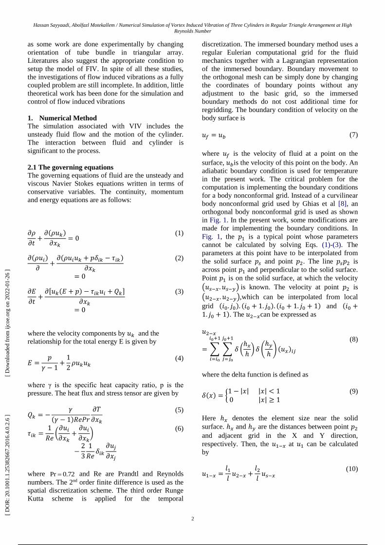
in Fig. 1. In the present work, some modifications are
made for implementing the boundary conditions. In
Fig. 1, the 𝑝1 is a typical point whose parameters
cannot be calculated by solving Eqs. (1)-(3). The
parameters at this point have to be interpolated from
the solid surface 𝑝𝑠 and point 𝑝2. The line 𝑝𝑠𝑝2 is
across point 𝑝1 and perpendicular to the solid surface.
Point 𝑝1 is on the solid surface, at which the velocity
(𝑢𝑠−𝑥 . 𝑢𝑠−𝑦) is known. The velocity at point 𝑝2 is
(𝑢2−𝑥. 𝑢2−𝑦),which can be interpolated from local
grid (𝑖0. 𝑗0). (𝑖0 + 1. 𝑗0). (𝑖0 + 1. 𝑗0 + 1) and (𝑖0 +1. 𝑗0 + 1). The 𝑢2−𝑥can be expressed as
𝑢2−𝑥
= ∑ ∑ 𝛿 (ℎ𝑥
ℎ)
𝑗0+1
𝑗=𝑗0
𝛿 (ℎ𝑦
ℎ)
𝑖0+1
𝑖=𝑖0
(𝑢𝑥)𝑖𝑗
(8)
where the delta function is defined as
𝛿(𝑥) = {1 − |𝑥| |𝑥| < 1 0 |𝑥| ≥ 1
(9)
Here ℎ𝑥 denotes the element size near the solid
surface. ℎ𝑥 and ℎ𝑦 are the distances between point 𝑝2
and adjacent grid in the X and Y direction,
respectively. Then, the 𝑢1−𝑥 at 𝑢1 can be calculated
by
𝑢1−𝑥 =𝑙1
𝑙𝑢2−𝑥 +
𝑙2
𝑙𝑢𝑠−𝑥
(10)
[ D
OR
: 20.
1001
.1.2
5382
667.
2016
.4.0
.2.6
]
[ D
ownl
oade
d fr
om ij
coe.
org
on 2
022-
01-2
6 ]
2 / 10
Hassan Sayyaadi, Abolfazl Motekallem / IJCOE 2016, No. 4; 1-10
3
Fig. 1. Schematic showing an immersed boundary on an orthogonal body nonconformal grid.
where 𝑙1 is the distance between points 𝑝1 and 𝑝𝑠, and
𝑙2 is the distance between points 𝑝1 and 𝑝2. 𝑙 is 𝑙1 +𝑙2 + 𝑙3 set to 1 ∙ 5ℎ, which ensures that the
interpolation of parameters at point 𝑝2 is independent
of parameters at point 𝑝1. Temperature at 𝑝1 is
determined by assuming adiabatic condition at Point
𝑝𝑠 and the density is determined by applying the
equation of state at the wall.
In this simulation, drag and lift force coefficients are
used to quantify the hydrodynamic characteristics.
The definitions are also given here:
𝐶𝑥 =𝐹𝑥
1
2𝜌𝑈2𝐷𝐿
(11)
𝐶𝑦 =𝐹𝑦
1
2𝜌𝑈2𝐷𝐿
(12)
Here 𝐹𝑥 and 𝐹𝑦 are the fluid forces exerted on the
bodies, respectively, in streamwise and transverse
directions and are calculated by performing an
integration along the wall, involving both pressure and
viscous effects:
𝐹𝑥 = − ∫ (𝑝𝑛 + 𝜇𝑛
𝑆
× 𝜔)𝑛𝑥𝑑𝑎
(13)
𝐹𝑦 = − ∫ (𝑝𝑛 + 𝜇𝑛
𝑆
× 𝜔)𝑛𝑦𝑑𝑎
(14)
where 𝜔 = ∇𝑢, whose value is calculated from the
velocities at points 𝑝𝑠 and 𝑝2 in Fig. 1. The pressure
on the surface is extrapolated from the interior of the
flow onto the boundary. n denotes the outward unit
normal to the cylinder surface. 𝑛𝑥 and 𝑛𝑦 are the
Cartesian components of 𝒏 ∙ 𝑆 represents the cylinder
surface. In order to analyze the aerodynamic behavior
of VIV, we define the instantaneous potential added-
mass and vortex force coefficients as
𝐶𝑃𝑜𝑡𝑒𝑛𝑡𝑖𝑎𝑙(𝑡)
= 2𝜋3[𝑦(𝑡)/𝐷]
(𝑈∗/𝑓∗)2
(15)
𝐶𝑉𝑜𝑟𝑡𝑒𝑥(𝑡)= 𝐶𝑦(𝑡) − 𝐶𝑃𝑜𝑡𝑒𝑛𝑡𝑖𝑎𝑙(𝑡)
(16)
which are same as the definitions used by Govardhan
and Williamson [9], 𝐶𝑃𝑜𝑡𝑒𝑛𝑖𝑎𝑙(𝑡) is always in phase
with the cylinder motion 𝑦(𝑡). Frequency ratio 𝑓∗ =𝑓/𝑓𝑁; reduced velocity 𝑈∗ = 𝑈/𝑓𝑁𝐷; and y is the
displacement in transverse direction.
2.2. The equations for a rigid cylinder
The motion of the elastically mounted rigid cylinder is
restricted in the transverse direction (Y axis in the
present simulation), and is governed by
Vibration equations,
𝑚�̈� + 𝑐�̇� + 𝑘𝑥 = 𝐹 (17)
Force in X direction,
𝑚�̈� + 𝑐�̇� + 𝑘𝑥 = 𝐹𝑥 (18)
Force in Y direction,
𝑚�̈� + 𝑐�̇� + 𝑘𝑥 = 𝐹𝑦 (19)
Where, the forces 𝐹𝑥 and 𝐹𝑦 are the total drag and lift
forces acting on the cylinder and ,𝑐 and 𝑘 are the tube
[ D
OR
: 20.
1001
.1.2
5382
667.
2016
.4.0
.2.6
]
[ D
ownl
oade
d fr
om ij
coe.
org
on 2
022-
01-2
6 ]
3 / 10
Hassan Sayyaadi, Abolfazl Motekallem / Numerical Simulation of Vortex Induced Vibration of Three Cylinders in Regular Triangle Arrangement at High
Reynolds Number
4
mass per unit length, structural damping coefficient
and spring constant respectively.
Drag and Lift coefficient,
𝐶𝐷 =𝐹𝐷
1
2𝜌𝑈∞
2 𝐷
(20)
𝐶𝐿 =𝐹𝐿
1
2𝜌𝑈∞
2 𝐷
(21)
Where, 𝐹𝑥 and 𝐹𝑦 are the total drag and lift forces
exerted by the fluid acting on cylinder per unit
cylinder length. Therefore 𝐶𝐷 = 𝐶𝐷𝑃 + 𝐶𝐷𝐹where 𝐶𝐷𝑃
and 𝐶𝐷𝐹 are pressure and friction drag coefficients
respectively. The frequency of vortex shedding (𝑓 ) in
wake region is given by Strouhal number (𝑆𝑡) and it is
defined as
𝑆𝑡 =𝑓𝐷
𝑈∞
(22)
Vortex shedding from a smooth, circular cylinder in a
steady flow is a function of Reynolds number. The
Reynolds number is based on free stream velocity U
and cylinder diameter D,
𝑅𝑒 =𝜌𝑈∞𝐷
𝜇
(23)
The cylinder has been modeled as a two degree of
freedom system with independent responses in X the
drag direction, and Y the lift direction. The initial
conditions of the cylinder are zero displacement and
velocity. As discussed in the introduction, the
response is assumed to be two dimensional with
symmetry along the cylinder axis. The following
properties are applied:
k - Stiffness is 25.5742 N / m
m - Mass per unit length is 7.804kg / m
2. FSI Solution of ANSYS
The VIV behavior of a circular cylinder is simulated
by a transient coupled FSI numerical model using the
combination of CFX and ANSYS transient structure
platforms. The well designed FSI solution scheme
provides tight integrations between hydrodynamics
and structural physics, offering a flexible, advanced
structure fluid analysis tool. The geometry module
provides a geometric model for the transient structure
solver and the ANSYS CFX solver. Coupled
simulations begin with the execution of the ANSYS
transient structure and ANSYS CFX solvers. The
system coupling solver acts as a coupling master
process to which the transient structure solver and
ANSYS CFX solvers connect. Once that connection is
established, the solvers advance through a sequence of
predefined synchronization points (SP). At each of
these SPs, the ANSYS CFX solver transfers the fluid
dynamic loads data to the transient structure solver
based on the system coupling solver; in turn, the
transient structure solver transfers the structure
response data to the ANSYS CFX solver also based
on the system coupling solver. Finally, the mesh is
updated with the diffusion based smoothing method
based on the response of the cylinder. The coupled
simulation proceeds in time during the outer loop.
Staggered iterations are repeated until a maximum
number of stagger iterations is reached or until the
data transferred between solvers and all field
equations have converged. The adoption of implicit
coupling iteration ensures that fluid and structure
solution fields are consistent with each other at the
end of each multi field step, leading to improved
numerical solution stability.
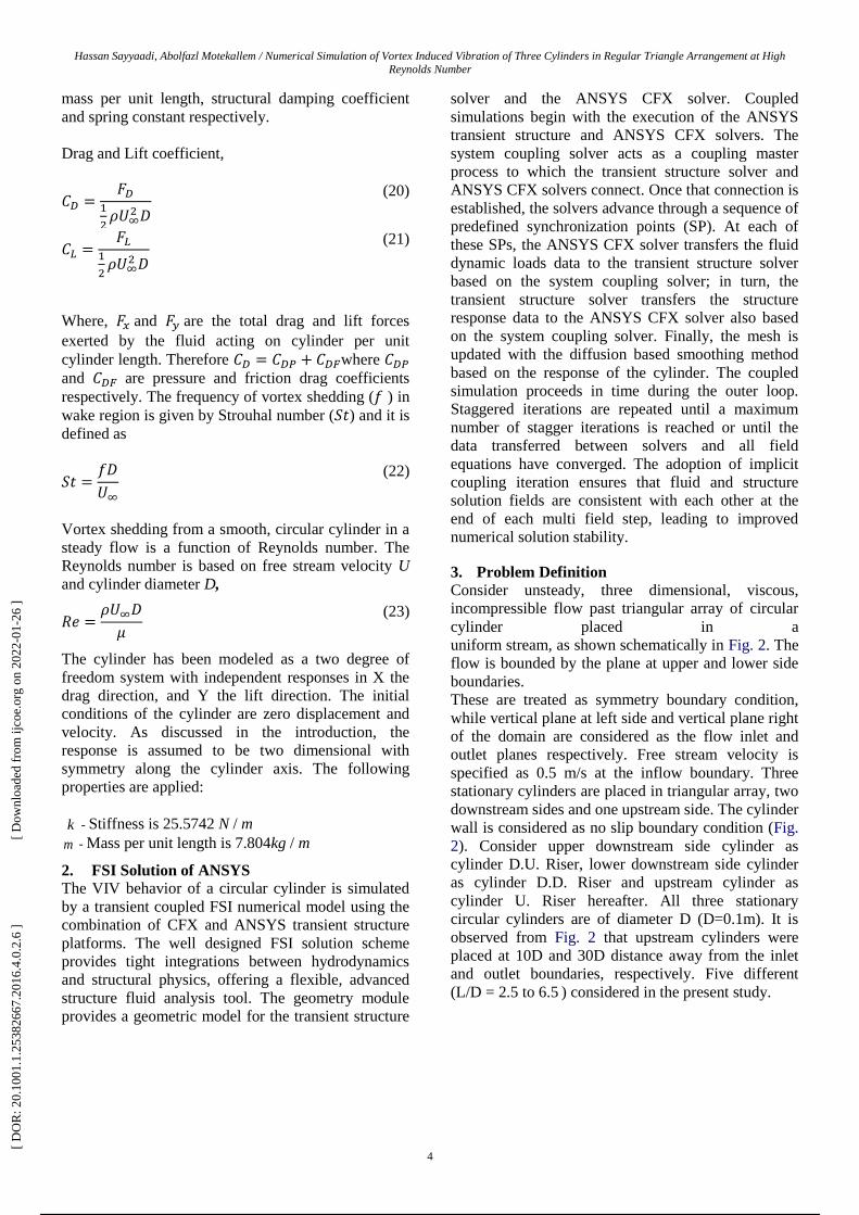
3. Problem Definition
Consider unsteady, three dimensional, viscous,
incompressible flow past triangular array of circular
cylinder placed in a
uniform stream, as shown schematically in Fig. 2. The
flow is bounded by the plane at upper and lower side
boundaries.
These are treated as symmetry boundary condition,
while vertical plane at left side and vertical plane right
of the domain are considered as the flow inlet and
outlet planes respectively. Free stream velocity is
specified as 0.5 m/s at the inflow boundary. Three
stationary cylinders are placed in triangular array, two
downstream sides and one upstream side. The cylinder
wall is considered as no slip boundary condition (Fig.
2). Consider upper downstream side cylinder as
cylinder D.U. Riser, lower downstream side cylinder
as cylinder D.D. Riser and upstream cylinder as
cylinder U. Riser hereafter. All three stationary
circular cylinders are of diameter D (D=0.1m). It is
observed from Fig. 2 that upstream cylinders were
placed at 10D and 30D distance away from the inlet
and outlet boundaries, respectively. Five different
(L/D = 2.5 to 6.5 ) considered in the present study.
[ D
OR
: 20.
1001
.1.2
5382
667.
2016
.4.0
.2.6
]
[ D
ownl
oade
d fr
om ij
coe.
org
on 2
022-
01-2
6 ]
4 / 10
Hassan Sayyaadi, Abolfazl Motekallem / IJCOE 2016, No. 4; 1-10
5
Fig. 2. Schematic of 2 DOF computational domains.
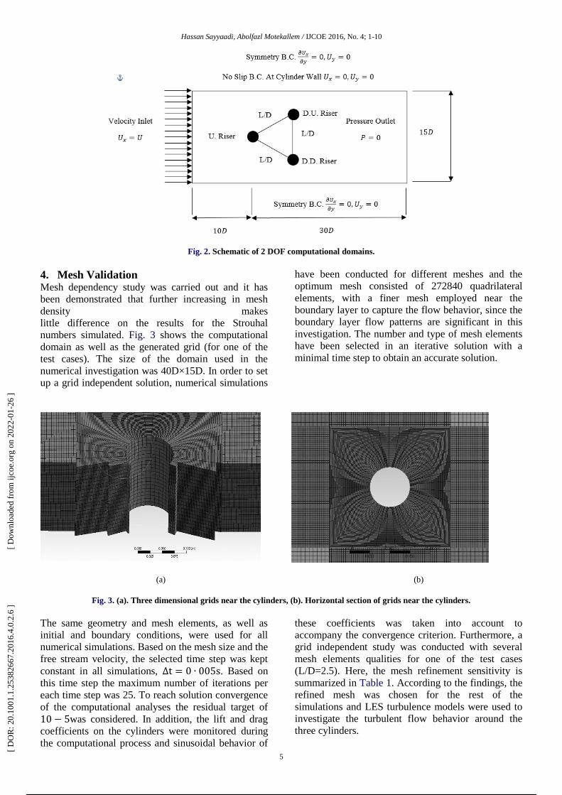
4. Mesh Validation Mesh dependency study was carried out and it has
been demonstrated that further increasing in mesh
density makes
little difference on the results for the Strouhal
numbers simulated. Fig. 3 shows the computational
domain as well as the generated grid (for one of the
test cases). The size of the domain used in the
numerical investigation was 40D×15D. In order to set
up a grid independent solution, numerical simulations
have been conducted for different meshes and the
optimum mesh consisted of 272840 quadrilateral
elements, with a finer mesh employed near the
boundary layer to capture the flow behavior, since the
boundary layer flow patterns are significant in this
investigation. The number and type of mesh elements
have been selected in an iterative solution with a
minimal time step to obtain an accurate solution.
(a) (b)
Fig. 3. (a). Three dimensional grids near the cylinders, (b). Horizontal section of grids near the cylinders.
The same geometry and mesh elements, as well as
initial and boundary conditions, were used for all
numerical simulations. Based on the mesh size and the
free stream velocity, the selected time step was kept
constant in all simulations, ∆t = 0 ∙ 005s. Based on
this time step the maximum number of iterations per
each time step was 25. To reach solution convergence
of the computational analyses the residual target of
10 − 5was considered. In addition, the lift and drag
coefficients on the cylinders were monitored during
the computational process and sinusoidal behavior of
these coefficients was taken into account to
accompany the convergence criterion. Furthermore, a
grid independent study was conducted with several
mesh elements qualities for one of the test cases
(L/D=2.5). Here, the mesh refinement sensitivity is
summarized in Table 1. According to the findings, the
refined mesh was chosen for the rest of the
simulations and LES turbulence models were used to
investigate the turbulent flow behavior around the
three cylinders.
[ D
OR
: 20.
1001
.1.2
5382
667.
2016
.4.0
.2.6
]
[ D
ownl
oade
d fr
om ij
coe.
org
on 2
022-
01-2
6 ]
5 / 10
Hassan Sayyaadi, Abolfazl Motekallem / Numerical Simulation of Vortex Induced Vibration of Three Cylinders in Regular Triangle Arrangement at High
Reynolds Number
6
Table 1: Mesh Dependence Study at 𝑹𝒆 = 𝟒 ∙ 𝟗𝟕 × 𝟏𝟎𝟓 and 𝑼∗ = 𝟓 ∙ 𝟓 for different meshes.
Mesh Case Number of
Elements
Lift Frequency Drag Frequency 𝒇𝒙/𝒇𝒚 Strouhal Number
1 122700 0.75 1.56 2.08 0.15
2 272840 0.85 1.71 2.01 0.17
3 491250 0.85 1.76 2.07 0.17
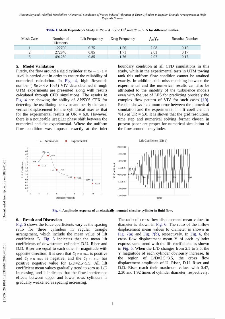
5. Model Validation
Firstly, the flow around a rigid cylinder at 𝑅𝑒 = 1 ∙ 1 ×
10𝑒5 is carried out in order to ensure the reliability of
numerical calculation. In Fig. 4, high Reynolds
number ( 𝑅𝑒 > 4 × 10𝑒5) VIV data obtained through
UTM experiments are presented along with results
calculated through CFD simulations. The results in
Fig. 4 are showing the ability of ANSYS CFX for
detecting the oscillating behavior and nearly the same
vertical displacement for the cylindrical riser as that
for the experimental results at UR = 6.0. However,
there is a noticeable irregular phase shift between the
numerical and the experimental. Where the uniform
flow condition was imposed exactly at the inlet
boundary condition at all CFD simulations in this
study, while in the experimental tests in UTM towing
tank this uniform flow condition cannot be attained
exactly. In addition, this miss matching between the
experimental and the numerical results can also be
attributed to the inability of the turbulence models
even with the use of LES for predicting precisely the
complex flow pattern of VIV for such cases [10].
Results shows maximum error between the numerical
simulation and the experimental in lift coefficient is
%16 at UR = 5.0. It is shown that the grid resolution,
time step and numerical solving format chosen in
present paper are proper for numerical simulation of
the flow around the cylinder.
Fig. 4. Amplitude response of an elastically mounted circular cylinder in fluid flow.
6. Result and Discussion
Fig. 5 shows the force coefficients vary as the spacing
ratio for three cylinders in regular triangle
arrangement, which include the mean value of lift
coefficient 𝐶𝑙. Fig. 5 indicates that the mean lift
coefficients of downstream cylinders D.U. Riser and
D.D. Riser are equal to each other in magnitude with
opposite direction. It is seen that 𝐶𝑙 D.U. Riser is positive
and 𝐶𝑙 D.D. Riser is negative, and the 𝐶𝑙 U. Riser has
positive negative value for L/D=2.5~5.5. All lift
coefficient mean values gradually trend to zero as L/D
increasing, and it indicates that the flow interference
effects between upper and lower rows cylinders is
gradually weakened as spacing increasing.
The ratio of cross flow displacement mean values to
diameter is shown in Fig. 6. The ratio of the inflow
displacement mean values to diameter is shown in
Fig. 7(a) and Fig. 7(b), respectively. In Fig. 6, the
cross flow displacement mean Y of each cylinder
express same trend with the lift coefficients as shown
in Fig. 5. When the L/D changes from 2.5 to 3.5, the
Y magnitude of each cylinder obviously increase. In
the region of L/D=2.5~3.5, the cross flow
displacement amplitude of U. Riser, D.U. Riser and
D.D. Riser reach their maximum values with 0.47,
2.30 and 1.92 times of cylinder diameter, respectively.
2.06
2.72
1.45
0.95
0.77
1.771
2.479
1.495
0.92
0.518
0
0.2
0.4
0.6
0.8
1
1.2
1.4
1.6
1.8
2
2.2
2.4
2.6
2.8
3
3 4 5 6 7 8 9 10 11
Lif
t C
oef
fici
ent
Reduecd Velocity
Simulation Experimental
-1.50E+00
-1.00E+00
-5.00E-01
0.00E+00
5.00E-01
1.00E+00
1.50E+00
2.00E+00
0 200 400 600 800
Lif
t C
oef
fici
ent
Time
Lift Coefficient (UR 6)
[ D
OR
: 20.
1001
.1.2
5382
667.
2016
.4.0
.2.6
]
[ D
ownl
oade
d fr
om ij
coe.
org
on 2
022-
01-2
6 ]
6 / 10
Hassan Sayyaadi, Abolfazl Motekallem / IJCOE 2016, No. 4; 1-10
7
Fig. 5. Mean values of lift coefficients versus L/D.
Fig. 6. Mean values of Y directions displacement versus L/D
In Fig. 7(a), it can be seen that the inflow displacement means X D.U. Riser, X D.D. Riser of downstream cylinders have the same
changing trend and increase in the all L/D range. The X U. Riser of upstream cylinder gradually increases from 0.31 to 0.64 as
L/D increases and reaches the maximum value at L/D=6.5 that shown in Fig. 7(b).
(a)
(b)
Fig. 7. (a). Mean values of X directions displacement versus L/D, (b). Mean values of X U. Riser directions displacement
versus L/D
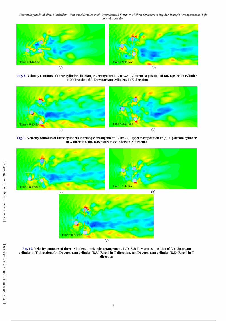
Finally, contours of flow velocity of the model are
shown in Fig. 8 to 11. The distance between the
spacing ratio is considered L/D=3.5 that have
maximum cross flow displacement. The velocity
contours are shown when the oscillating cylinders are
at their uppermost and lowermost positions. Fig. 8
shows the results for L/D=3.5 when all cylinders are
at their minimum position in X direction and Fig. 9
shows the same contours for the maximum position in
X direction. As it can be seen, the movement of
downstream cylinders is more than upstream cylinder
and also another thing that should be mention is the
upstream cylinder never goes behind the reference
point and all of its movements are in right hand of the
reference point. In the other hand, the downstream
cylinders, moves either in left or right hand of the
reference point. The maximum amplitude for
upstream cylinder in X direction is almost 0.64D and
for downstream cylinders is slightly below 0.54D.
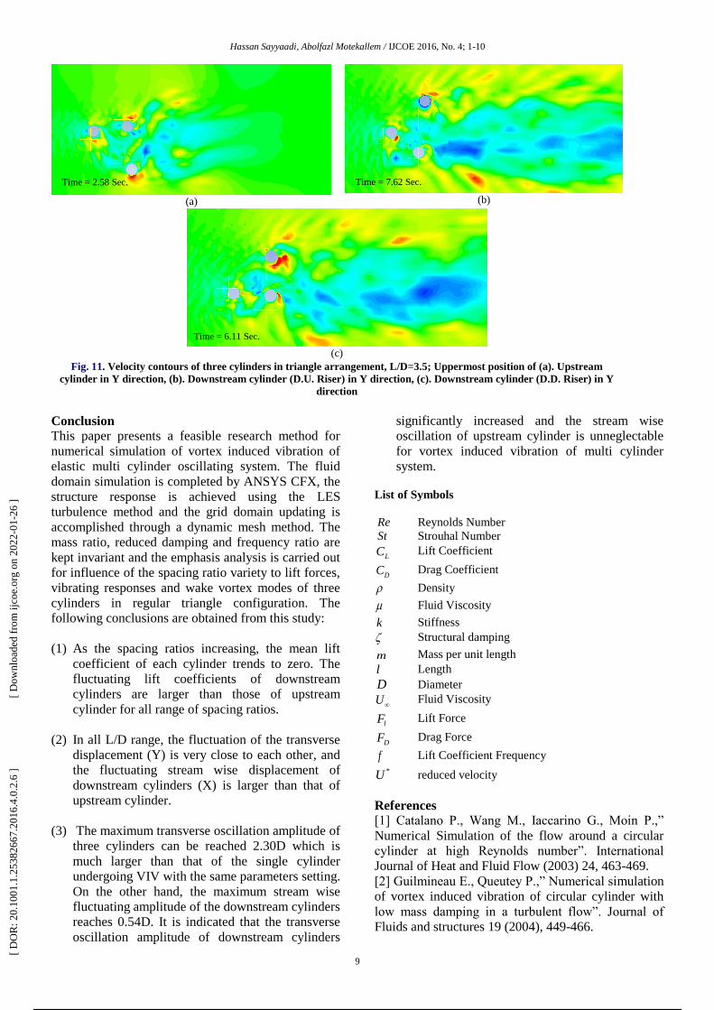
Fig. 10 shows the results for L/D=3.5 when the both
cylinders are at their minimum positions in Y
direction and Fig. 11 the same results when they are at
their maximum positions in Y direction. For the
upstream cylinder the maximum amplitude is about
0.47D and for downstream cylinders is almost 2.30
and 1.92 for D.U. Riser and D.D. Riser, respectively.
It shows that downstream cylinders at L/D=3.5, have
the same of movement and this is the exception
because as can be seen in Fig.6, at all other spacing
ratio, there are a different amplitude in Y direction for
cylinders. Also the counter of velocity shows that the
shear layers roll down after the downstream body and
roll up after the upstream body.
-1.5
-1
-0.5
0
0.5
1
1.5
2 2.5 3 3.5 4 4.5 5 5.5 6 6.5 7
Cl
L/D
Lift Coefficient
U.Riser D.U.Riser D.D.Riser
-2.5
-2
-1.5
-1
-0.5
0
0.5
1
1.5
2
2.5
3
2 2.5 3 3.5 4 4.5 5 5.5 6 6.5 7
Y/D
L/D
Transverse Displacement
U.Riser D.U.Riser D.D.Riser
0.3
0.35
0.4
0.45
0.5
0.55
0.6
0.65
0.7
2 2.5 3 3.5 4 4.5 5 5.5 6 6.5 7
X/D
L/D
Streamwise Displacement
U.Riser D.U.Riser D.D.Riser
0.3
0.35
0.4
0.45
0.5
0.55
0.6
0.65
0.7
2 2.5 3 3.5 4 4.5 5 5.5 6 6.5 7
X/D
L/D
Streamwise Displacement
U.Riser
[ D
OR
: 20.
1001
.1.2
5382
667.
2016
.4.0
.2.6
]
[ D
ownl
oade
d fr
om ij
coe.
org
on 2
022-
01-2
6 ]
7 / 10
Hassan Sayyaadi, Abolfazl Motekallem / Numerical Simulation of Vortex Induced Vibration of Three Cylinders in Regular Triangle Arrangement at High
Reynolds Number
8
(a)
(b)
Fig. 8. Velocity contours of three cylinders in triangle arrangement, L/D=3.5; Lowermost position of (a). Upstream cylinder
in X direction, (b). Downstream cylinders in X direction
(a)
(b)
Fig. 9. Velocity contours of three cylinders in triangle arrangement, L/D=3.5; Uppermost position of (a). Upstream cylinder
in X direction, (b). Downstream cylinders in X direction
(a)
(b)
(c)
Fig. 10. Velocity contours of three cylinders in triangle arrangement, L/D=3.5; Lowermost position of (a). Upstream
cylinder in Y direction, (b). Downstream cylinder (D.U. Riser) in Y direction, (c). Downstream cylinder (D.D. Riser) in Y
direction
Time = 8.49 Sec.
Time = 3.44 Sec. Time = 9.09 Sec.
Time = 8.16 Sec. Time = 3.91 Sec.
Time = 2.47 Sec.
Time = 2.47 Sec.
Time = 8.22 Sec.
[ D
OR
: 20.
1001
.1.2
5382
667.
2016
.4.0
.2.6
]
[ D
ownl
oade
d fr
om ij
coe.
org
on 2
022-
01-2
6 ]
8 / 10
Hassan Sayyaadi, Abolfazl Motekallem / IJCOE 2016, No. 4; 1-10
9
(a)
(b)
(c)
Fig. 11. Velocity contours of three cylinders in triangle arrangement, L/D=3.5; Uppermost position of (a). Upstream
cylinder in Y direction, (b). Downstream cylinder (D.U. Riser) in Y direction, (c). Downstream cylinder (D.D. Riser) in Y
direction
Conclusion
This paper presents a feasible research method for
numerical simulation of vortex induced vibration of
elastic multi cylinder oscillating system. The fluid
domain simulation is completed by ANSYS CFX, the
structure response is achieved using the LES
turbulence method and the grid domain updating is
accomplished through a dynamic mesh method. The
mass ratio, reduced damping and frequency ratio are
kept invariant and the emphasis analysis is carried out
for influence of the spacing ratio variety to lift forces,
vibrating responses and wake vortex modes of three
cylinders in regular triangle configuration. The
following conclusions are obtained from this study:
(1) As the spacing ratios increasing, the mean lift
coefficient of each cylinder trends to zero. The
fluctuating lift coefficients of downstream
cylinders are larger than those of upstream
cylinder for all range of spacing ratios.
(2) In all L/D range, the fluctuation of the transverse
displacement (Y) is very close to each other, and
the fluctuating stream wise displacement of
downstream cylinders (X) is larger than that of
upstream cylinder.
(3) The maximum transverse oscillation amplitude of
three cylinders can be reached 2.30D which is
much larger than that of the single cylinder
undergoing VIV with the same parameters setting.
On the other hand, the maximum stream wise
fluctuating amplitude of the downstream cylinders
reaches 0.54D. It is indicated that the transverse
oscillation amplitude of downstream cylinders
significantly increased and the stream wise
oscillation of upstream cylinder is unneglectable
for vortex induced vibration of multi cylinder
system.
List of Symbols
Re Reynolds Number
St Strouhal Number
LC Lift Coefficient
DC Drag Coefficient
Density
Fluid Viscosity
k Stiffness
Structural damping
m Mass per unit length
l Length
D Diameter
U Fluid Viscosity
lF Lift Force
DF Drag Force
f Lift Coefficient Frequency
*U reduced velocity
References
[1] Catalano P., Wang M., Iaccarino G., Moin P.,”
Numerical Simulation of the flow around a circular
cylinder at high Reynolds number”. International
Journal of Heat and Fluid Flow (2003) 24, 463-469.
[2] Guilmineau E., Queutey P.,” Numerical simulation
of vortex induced vibration of circular cylinder with
low mass damping in a turbulent flow”. Journal of
Fluids and structures 19 (2004), 449-466.
Time = 2.58 Sec. Time = 7.62 Sec.
Time = 7.62 Sec.
Time = 6.11 Sec.
[ D
OR
: 20.
1001
.1.2
5382
667.
2016
.4.0
.2.6
]
[ D
ownl
oade
d fr
om ij
coe.
org
on 2
022-
01-2
6 ]
9 / 10
Hassan Sayyaadi, Abolfazl Motekallem / Numerical Simulation of Vortex Induced Vibration of Three Cylinders in Regular Triangle Arrangement at High
Reynolds Number
10
[3] Huang Z., Olson J.A., Kerekes R.J., Green S.I.,”
Numerical simulation of the flow around rows of
cylinders”, Computers and Fluids 35 (2006), 485-491.
[4] Lam K., Lin Y.F., Zou L., Liu Y.,” Experimental
study and large eddy simulation of turbulent flow
around tube bundles composed of wavy and circular
cylinders”. International Journal of Heat and Fluid 31
(2010)32-44.
[5] Mittal S., Kumar V.,” Flow induced vibration of
circular cylinder in tandem and staggered
arrangement”, Journal of Fluids and Structures 15
(2001), 717-736.
[6] Ponta F.L., Aref H.,” Numerical experiments on
vortex shedding from an oscillating cylinder”, Journal
of Fluids and Structures 22 (2006), 327-344.
[7] Williamson C.H.K.,” Three dimensional vortex
dynamics in bluff body wakes”, Experimental
Thermal and Fluid Science 12(1996), 150-168.
[8] Ghias, R., Mittal, R., Dong, H.,” A sharp interface
immersed boundary method for compressible viscous
flows”, Journal of Computational Physics 225(2006),
528–553.
[9] Govardhan, R., Williamson, C.H.K.,” Modes of
vortex formation and frequency response for a freely
vibrating cylinder”, Journal of Fluid Mechanics
420(2000), 85–130.
[10] F. Saltara, A. D. Agostini Nato, J. I. Z Lopez.
2011. 3D CFD Simulation of Vortex induced
Vibration of Cylinder. International Journal of
Offshore and Polar Engineering. 21(3): 192–197.
[ D
OR
: 20.
1001
.1.2
5382
667.
2016
.4.0
.2.6
]
[ D
ownl
oade
d fr
om ij
coe.
org
on 2
022-
01-2
6 ]
Powered by TCPDF (www.tcpdf.org)
10 / 10
![EXPERIMENTS ON VORTEX-INDUCED VIBRATION …ijame.ump.edu.my/images/Volume_11 June 2015/31_Rahman and... · EXPERIMENTS ON VORTEX-INDUCED VIBRATION OF A VERTICAL ... Blevins [10],](https://img.pdfslide.net/doc/110x75/5b83b77d7f8b9a31608def8f/experiments-on-vortex-induced-vibration-ijameumpedumyimagesvolume11-june-201531rahman.jpg)