Embed Size (px)
Citation preview

1
Numerical Simulations of High Temperature Jets from the Main Propulsion System and Auxiliary Power Unit Impinging Against a Construction of
the Passenger Plane
Kudryavtsev A. Yu., Zhelezov S.A., (Sarov Engineering Center)
Polovin M.M., Litvinov M.S. (Sukhoi Civil Aircraft)
STAR Global Conference 2012, March 19-21, Amsterdam

2
MPU APU Accidental High Temperature Jets
STAR Global Conference 2012, March 19-21, Amsterdam
All newly designed passenger planes must meet safety and reliability requirements in possible emergency situations, one of which is a burn-through of a combustion chamber body of the main propulsion system (MPS) and auxiliary power unit (APU) both on the ground and in flight.

3
Problem Statement
In accordance with the international safety standards, an emergency case is investigated using STAR-CCM+ and Abaqus when due to local disruption of the combustion chamber a flame jet is erupted. As a result of the flame jet impingement some parts of the airplane construction can substantially be heated, deformed and, possibly, disrupted. The following variants of jet are considered: 1. MPS: Temperature and pressure in the combustion chamber: Тflame=1527ºС, Р=22,3 bar; 2. APU: Temperature and pressure in the combustion chamber: Тflame =1015ºС, Р=10,6 bar. Duration of the flame jet eruption t ≤ 5 sec in all cases. This presentation gives results of numerical investigations of deformation of airplane parts entering the zone of possible gas-dynamic and thermal effects from the flame jet.
STAR Global Conference 2012, March 19-21, Amsterdam

4
Methodology of simulation Solution of the problem is divided into three stages : 1. Gas-dynamic problem 2. Heat-transfer problem 3. Stress analysis problem
The result of solving the gas-dynamic problem is the pressure, temperature and the heat transfer coefficient on the surfaces. Temperature and HTC are then used as boundary conditions for solving the heat transfer problem. The result of solving the heat problem is a three-dimensional temperature field for all the details. The resulting solution of the temperature field is interpolated on the finite element model, where it is based on the calculated mechanical properties of materials.
Tambient, Htran
Tvolume
Heat transfer problem
Stress analysis problem
Gas-dynamic problem
Pressure
STAR Global Conference 2012, March 19-21, Amsterdam
5
Methodology of simulation
Gas-dynamic problems are solved in a steady-state formulation, stress - in the static. The thermal calculations were carried out both in steady-state and in transient variant. The calculation results show that during the jet flame impact T = 5 sec., the temperature of the studied elements of the airframe and the pylon reaches maximum, and does not to grow up further. A solution of the stationary and transient problem for final moment of time are identical. With regard to the this type of problem, the steady-state solution is worse and provide heavier loads to parts of the airplane construction than the solution of the transient problem for any finite time.
STAR Global Conference 2012, March 19-21, Amsterdam

6
Case 1: APU high temperature jet
STAR Global Conference 2012, March 19-21, Amsterdam
Computer model: • based on the polyhedral cells • 5 mln cells for fluid • 3 mln cell for solid

7
Finite element model, contains 366 000 elements
Case 1: APU high temperature jet
STAR Global Conference 2012, March 19-21, Amsterdam

8 STAR Global Conference 2012, March 19-21, Amsterdam
Case 1: APU high temperature jet
Pressure Temperature

9 STAR Global Conference 2012, March 19-21, Amsterdam
Case 1: APU high temperature jet
Temperature reaches maximum value Tmax = 850 C at the time t = 0.1 sec., which is much less than melting temperature for this material Tmelting = 1640 C

10
Contours of resultant displacement (m)
Case 1: APU high temperature jet
STAR Global Conference 2012, March 19-21, Amsterdam

11
Conclusions: • through hole does not appear due to of melting;
• rupture of the part in the zone of the maximum pressure does not occur.
Case 1: APU high temperature jet
STAR Global Conference 2012, March 19-21, Amsterdam

12
Case 2: MPU high temperature jet
STAR Global Conference 2012, March 19-21, Amsterdam
Computer model: • based on the trimmed cells • 3 mln cells for fluid • 0.5 mln cell for solid
13
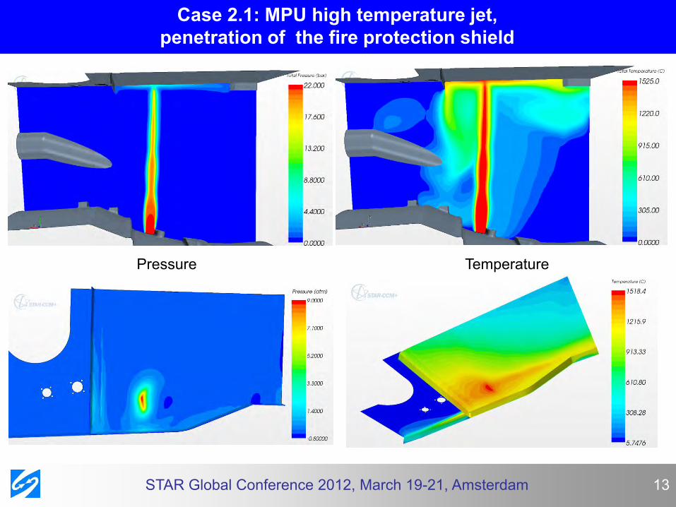
Case 2.1: MPU high temperature jet, penetration of the fire protection shield
STAR Global Conference 2012, March 19-21, Amsterdam
Pressure Temperature

14
In this case temperature of jet is T = 1527 C and melting temperature T = 1496 C. Temperature of the shield reaches critical value to the t = 2.5 sec. Therefore it is expected that though hole will appear just due to the melting. But size of hole can increase as result of jet pressure force.
Case 2.1: MPU high temperature jet, penetration of the fire protection shield
STAR Global Conference 2012, March 19-21, Amsterdam

15
Evolution of the cavern in time
Case 2.1: MPU high temperature jet, penetration of the fire protection shield
STAR Global Conference 2012, March 19-21, Amsterdam

16
Finite element model:
T = 2 sec.
Case 2.1: MPU high temperature jet, penetration of the fire protection shield
T = 4 sec.
T = 3.5 sec.
STAR Global Conference 2012, March 19-21, Amsterdam
17
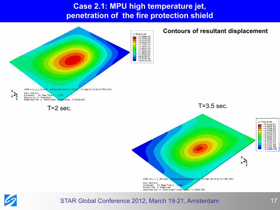
Т=2 sec. Т=3.5 sec.
Contours of resultant displacement
Case 2.1: MPU high temperature jet, penetration of the fire protection shield
STAR Global Conference 2012, March 19-21, Amsterdam

18
Т=4 sec. Т=5 sec.
Case 2.1: MPU, left side of the pylon, penetration of the fire protection shield
STAR Global Conference 2012, March 19-21, Amsterdam
Contours of resultant displacement

19
Conclusions: • at time ~ 3.5 sec. fire protection shield breaks though, hole continues enlarging mainly due to melting of the material, influence of jet pressure to size of hole is minor; • to the 5th second the hole takes the final shape and size, the further the increasing of hole does not occur.
Case 2.1: MPU high temperature jet, penetration of the fire protection shield
STAR Global Conference 2012, March 19-21, Amsterdam

20
Case 2.2: MPU high temperature jet, jet flame propagation
STAR Global Conference 2012, March 19-21, Amsterdam
Propagation of the jet flame into the compartment of pylon
Computer model: • based on the trimmer cells • 2.5 mln cells for fluid

21
Pressure Temperature
STAR Global Conference 2012, March 19-21, Amsterdam
Case 2.2: MPU high temperature jet, jet flame propagation
22
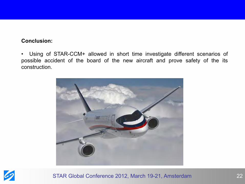
Conclusion: • Using of STAR-CCM+ allowed in short time investigate different scenarios of possible accident of the board of the new aircraft and prove safety of the its construction.
STAR Global Conference 2012, March 19-21, Amsterdam

23
Thank you for your attention
STAR Global Conference 2012, March 19-21, Amsterdam