Embed Size (px)
Citation preview
ISSN: 2277-9655
Lotfy Ehab, 7 (5): May, 2018] Impact Factor: 5.164
IC™ Value: 3.00 CODEN: IJESS7
http: // www.ijesrt.com © International Journal of Engineering Sciences & Research Technology
[257]
IJESRT INTERNATIONAL JOURNAL OF ENGINEERING SCIENCES & RESEARCH
TECHNOLOGY
NUMERICAL STUDY OF LONG COLUMNS STRENGTHENED BY FIBER
REINFORCED POLYMER (FRP) Ehab M. Lotfy, Acc. Prof.
Civil Engineering Department, Faculty of Engineering, Suez Canal University, Egypt
DOI: 10.5281/zenodo.1246981
ABSTRACT Strengthening of existing Reinforced Concrete structures is becoming a major issue in civil engineering.
Externally Bonded Reinforcement (EBR) systems have been successfully applied for strengthening of existing
concrete structures. This work includes a results of numerical models carried to investigate the behavior of
reinforced concrete, RC, slender columns with rectangular sections under the effect of eccentric loads
strengthened with carbon fiber-reinforced polymers (CFRPs) in three different manners in order to enhance its
axial and flexural rigidity. The first approach is a well-known form of CFRP strengthening with sheet wrapping
columns; the second approach is strengthening using CFRP sheets in longitudinal direction of columns, and a
third one is a new retrofitting method of near surface mounted (NSM) CFRP strips. Ten full scale specimens
with rectangular cross sections dimensions (210 × 150 mm) were tested under eccentric compressive loading to
failure. The total length of all specimens was 3000 mm, with slender ratios 73, 60 and 50 respectively and
characteristic strength 25, 35,45Mpa. NSM proved to be very effective in terms of increasing their flexural
resistance, as long as the NSM bars can be effectively anchored in the adjacent long columns.
KEYWORDS: Strengthening, Long Columns, Fiber Reinforced Polymer
I. INTRODUCTION Worldwide application in reinforced concrete (RC) technology for the last 100 years have shown that RC
structures exhibit a reliable and durable behavior when they are properly designed, built and maintained.
However, porosity and cracking of concrete, as well as corrosion of steel reinforcement can lead to deficiency of
existing RC structures especially when they are exposed to extreme and hostile environmental conditions and
excessive loads. Other causes of structural deficiency are design mistakes, increase in load carrying needs,
change of use of the structure, and adoption of more stringent design codes especially in seismic zones.
It is a well-known fact that the infrastructure of a country needs to be maintained either by demolishing the
deficient structures and building new ones, or by rehabilitating the old ones with appropriate techniques to meet
the current requirements for the continuity of modern civilization.
Unavoidably, countries which have had well established structural infrastructure for a long time are also the
ones to have problems with it due to aging of existing structures. Australia’s infrastructure condition was
assessed to be in urgent need of rehabilitation especially for the highway bridges. However, no cost figure has
been estimated for the rehabilitation. In USA, it was estimated that 40% of the 575000 highway bridges were
either structurally deficient or obsolete, and 25% were over 50 years old and unsuitable for the current or
projected traffic needs. The estimated cost for repairing all deteriorating bridges was US$78 billion; however,
only $5 billion a year was available for such repairs. Over the years, engineers have used different methods and
techniques to retrofit existing structures by providing external confining stresses. For the past few years, the
concept of jacketing has been investigated to provide such forces. Externally applied jackets have been used as a
reinforcement to contain concrete for different reasons. Engineers have used traditional materials such as wood,
steel, and concrete to confine and improve the structural behavior of concrete members Fiber reinforced
composite materials are becoming more frequently used in civil engineering structures. One of the most
practical applications of these new materials concerns the strengthening of reinforced concrete columns by
means of confinement with fiber composite sheets. The typical confining techniques that are widely used for
strengthening of columns, when it comes to columns with high slenderness ratio the confinement become more
ineffective [1,2,3].

ISSN: 2277-9655
Lotfy Ehab, 7 (5): May, 2018] Impact Factor: 5.164
IC™ Value: 3.00 CODEN: IJESS7
http: // www.ijesrt.com © International Journal of Engineering Sciences & Research Technology
[258]
There are three methods to apply an FRP jacket to strengthen a column [4]: (1) in-situ wrapping of FRP sheets
in a wet layup process; (2) in-situ formation of the jacket by filament winding; (3) use of prefabricated FRP
shells. The most commonly used method is the in-situ wrapping method which is also used as a technique for
strengthening in this present experimental study. The other two methods have been rarely used in practice.
Study focuses on slender RC column strengthening. RC columns are generally referred to as vertical load
carrying structural members. However, it is also known that this kind of classification is merely an idealization
as columns may also carry shear and bending moments depending on their position in the structure, uneven
settlements, workmanship errors and seismic loads. RC columns are constructed as highway bridge peers,
vertical load carrying members in buildings or underground piles. They are constructed in many different cross
sectional geometries and heights using different types and amounts of concrete and steel reinforcement
depending on the structural necessity and material availability[1]. To keep RC columns from further
deterioration due to materials’ vulnerability to hostile environment conditions and to restore their strength,
ductility and durability to a technically accepted level, there are a number of strengthening techniques developed
and tested. Steel jacketing and Fiber Reinforced Polymer (FRP) wrapping are the most commonly used
methods[5].
The most outstanding characteristic of the EBR technique is the ease and speed of installation compared to steel
plate bonding. One of the drawbacks of EBR systems is the susceptibility to mechanical damages as well as to
damage from environmental effects such as freeze thaw cycles due to direct exposure. Further, EBR systems are
easily susceptible to damage by fire and vandalism. Although this technique is well established among the
practitioners around the world, still there are some major concerns about some issues associated with this
technique, for instance, premature debonding failures causing delamination of FRP reinforcement from the
substrate at relatively low loads. The failure of a compression member has to do with the strength and stiffness
of the material and the geometry (slenderness ratio) of the member. Whether a compression member is
considered short, intermediate, or long depends on these factors [6]. Several design guidelines (fib 2001; ISIS
2001; ACI-440.2R 2002, 2008; JSCE 2002; CNR-DT200 2004; Concrete Society 2004) for external
strengthening of RC structures using FRP composites have been published as a result of extensive research and
enormous practical needs in this field. Nevertheless, relevant design provisions for FRP-confined RC columns
in these design guidelines are only applicable to the design of short columns with negligible slenderness effects.
Moreover, Only Concrete Society (2004) and ACI-440.2R (2008) have recommended a procedure to perform
section analysis of short FRP-confined RC columns so that columns subjected to combined bending and axial
compression can be designed accordingly, but they do not specify the corresponding design equations.
Therefore, a proper design procedure for FRP-confined RC columns is urgently needed [7]. Various methods have been used to provide confinement to Short columns using FRP composites. Among them,
in-situ FRP wrapping has been the most commonly used technique, in which fiber sheets or fabrics are
impregnated with resins and wrapped continuously or discretely around columns in a wet lay-up process, with
the main fibers solely or predominantly oriented in the hoop direction. This strengthening technique is
potentially effective for columns of various section shapes, but is particularly effective for circular columns.
Rectangular columns need to receive rounding of sharp corners or shape modifications before FRP jacketing to
enhance the effectiveness of confinement. For example, a rectangular section may be modified into an elliptical
section before FRP jacketing[8]. The Near Surface Mounted (NSM) FRP technique has emerged as a more
effective strengthening technique than the EBR technique in many instances because of its ability to gain higher
bond strengths and the possibility of precluding or delaying premature debonding failures, which are often
observed in the EBR technique.
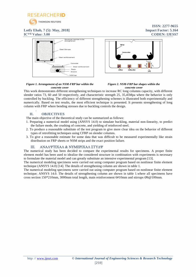
The NSM-FRP technique involves bonding FRP bars into precut grooves in the concrete cover of a structural
member to be strengthened, using an adhesive as shown in Figures 1& 2. The application of NSM technique
covers both reinforced and pre stressed concrete structures as well as structures made of other materials, such as
timber and masonry. Although only a limited number of research studies on NSM systems are currently
available, the research carried out so far indicates that the NSM technique is a promising and effective technique
in increasing both flexural and shear capacities of structural members such as beams [9, 10, 11, 12].
ISSN: 2277-9655
Lotfy Ehab, 7 (5): May, 2018] Impact Factor: 5.164
IC™ Value: 3.00 CODEN: IJESS7
http: // www.ijesrt.com © International Journal of Engineering Sciences & Research Technology
[259]
Figure 1. Arrangement of an NSM-FRP bar within the
concrete cover
Figure 2. NSM-FRP bar shapes within the
concrete cover
This work demonstrates different strengthening techniques to increase RC long columns capacity, with different
slender ratios 73, 60 and 50 respectively, and characteristic strength 25, 35,45Mpa where the behavior is only
controlled by buckling. The efficiency of different strengthening schemes is illustrated both experimentally and
numerically. Based on test results, the most efficient technique is presented. It presents strengthening of long
column with FRP where bending stresses due to buckling controls the design.
.
II. OBJECTIVES The main objective of the theoretical study can be summarized as follows:
1. Preparing a numerical model using (ANSYS 14.0) to simulate buckling, material non-linearity, to predict
the failure mode, the crushing of concrete, and yielding of reinforced steel.
2. To produce a reasonable substitute of the test program to give more clear idea on the behavior of different
types of retrofitting techniques using CFRP on slender columns.
3. To give a reasonable estimate for some data that was difficult to be measured experimentally like strain
distribution on FRP sheets or NSM strips and the exact position failure.
The numerical study has been decided to compare the experimental results for specimens. A proper finite
element model has been used to idealize the considered structure in combination with experiments is necessary
to formulate the material model and can greatly substitute an intensive experimental program [13].
The numerical modeling specimens were carried out using computer program based on nonlinear finite element
technique (ANSYS 14.0) [14]. The details of strengthening column are shown in table 1.
The numerical modeling specimens were carried out using computer program based on nonlinear finite element
technique; ANSYS 14.0. The details of strengthening column are shown in table 1.where all specimens have
cross section 150*210mm, 3000mm total length, main reinforcement 6#10mm and stirrups Ø6@100mm.
ISSN: 2277-9655
Lotfy Ehab, 7 (5): May, 2018] Impact Factor: 5.164
IC™ Value: 3.00 CODEN: IJESS7
http: // www.ijesrt.com © International Journal of Engineering Sciences & Research Technology
[260]
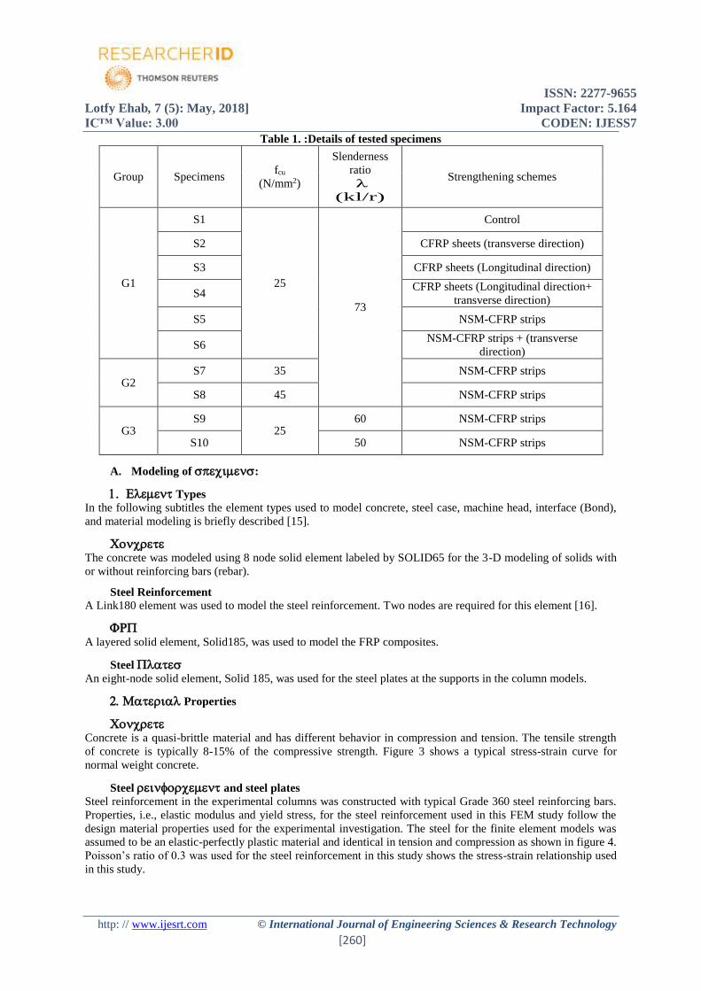
Table 1. :Details of tested specimens
Group Specimens fcu
(N/mm2)
Slenderness
ratio
λ
(kl/r)
Strengthening schemes
G1
S1
25
73
Control
S2 CFRP sheets (transverse direction)
S3 CFRP sheets (Longitudinal direction)
S4 CFRP sheets (Longitudinal direction+
transverse direction)
S5 NSM-CFRP strips
S6 NSM-CFRP strips + (transverse
direction)
G2 S7 35 NSM-CFRP strips
S8 45 NSM-CFRP strips
G3 S9
25 60 NSM-CFRP strips
S10 50 NSM-CFRP strips
A. Modeling of :
Types
In the following subtitles the element types used to model concrete, steel case, machine head, interface (Bond),
and material modeling is briefly described [15].
The concrete was modeled using 8 node solid element labeled by SOLID65 for the 3-D modeling of solids with
or without reinforcing bars (rebar).
Steel Reinforcement A Link180 element was used to model the steel reinforcement. Two nodes are required for this element [16].
A layered solid element, Solid185, was used to model the FRP composites.
Steel
An eight-node solid element, Solid 185, was used for the steel plates at the supports in the column models.
Properties
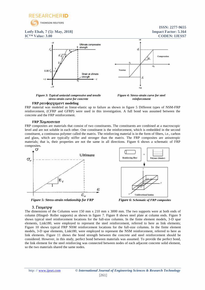
Concrete is a quasi-brittle material and has different behavior in compression and tension. The tensile strength
of concrete is typically 8-15% of the compressive strength. Figure 3 shows a typical stress-strain curve for
normal weight concrete.
Steel and steel plates
Steel reinforcement in the experimental columns was constructed with typical Grade 360 steel reinforcing bars.
Properties, i.e., elastic modulus and yield stress, for the steel reinforcement used in this FEM study follow the
design material properties used for the experimental investigation. The steel for the finite element models was
assumed to be an elastic-perfectly plastic material and identical in tension and compression as shown in figure 4.
Poisson’s ratio of 0.3 was used for the steel reinforcement in this study shows the stress-strain relationship used
in this study.
ISSN: 2277-9655
Lotfy Ehab, 7 (5): May, 2018] Impact Factor: 5.164
IC™ Value: 3.00 CODEN: IJESS7
http: // www.ijesrt.com © International Journal of Engineering Sciences & Research Technology
[261]
Figure 3: Typical uniaxial compressive and tensile
stress-strain curve for concrete
Figure 4: Stress-strain curve for steel
reinforcement
FRP modeling
FRP material was modeled as linear-elastic up to failure as shown in figure 5 Different types of NSM-FRP
reinforcement, (CFRP and GFRP) were used in this investigation. A full bond was assumed between the
concrete and the FRP reinforcement.
FRP
FRP composites are materials that consist of two constituents. The constituents are combined at a macroscopic
level and are not soluble in each other. One constituent is the reinforcement, which is embedded in the second
constituent, a continuous polymer called the matrix. The reinforcing material is in the form of fibers, i.e., carbon
and glass, which are typically stiffer and stronger than the matrix. The FRP composites are anisotropic
materials; that is, their properties are not the same in all directions. Figure 6 shows a schematic of FRP
composites.
Figure 5: Stress-strain relationship for FRP Figure 6: Schematic of FRP composites
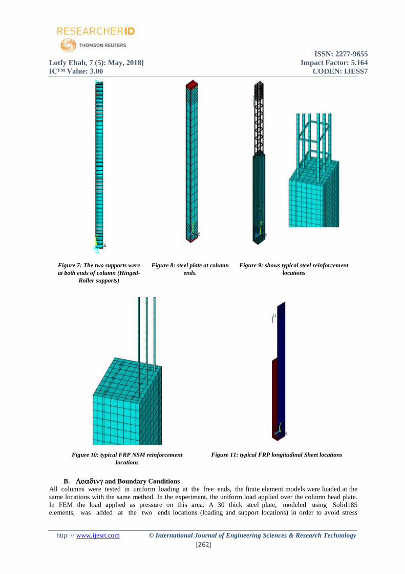
The dimensions of the Columns were 150 mm x 210 mm x 3000 mm. The two supports were at both ends of
column (Hinged- Roller supports) as shown in figure 7. Figure 8 shows steel plate at column ends. Figure 9
shows typical steel reinforcement locations for the full-size columns. In the finite element models, 3-D spar
elements, Link180, were employed to represent the steel reinforcement, referred to here as link elements;
Figure 10 shows typical FRP NSM reinforcement locations for the full-size columns. In the finite element
models, 3-D spar elements, Link180, were employed to represent the NSM reinforcement, referred to here as
link elements. Figure 11 shows the bond strength between the concrete and steel reinforcement should be
considered. However, in this study, perfect bond between materials was assumed. To provide the perfect bond,
the link element for the steel reinforcing was connected between nodes of each adjacent concrete solid element,
so the two materials shared the same nodes.
ISSN: 2277-9655
Lotfy Ehab, 7 (5): May, 2018] Impact Factor: 5.164
IC™ Value: 3.00 CODEN: IJESS7
http: // www.ijesrt.com © International Journal of Engineering Sciences & Research Technology
[262]
Figure 7: The two supports were
at both ends of column (Hinged-
Roller supports)
Figure 8: steel plate at column
ends.
Figure 9: shows typical steel reinforcement
locations
Figure 10: typical FRP NSM reinforcement
locations
Figure 11: typical FRP longitudinal Sheet locations
B. and Boundary Conditions
All columns were tested in uniform loading at the free ends, the finite element models were loaded at the
same locations with the same method. In the experiment, the uniform load applied over the column head plate.
In FEM the load applied as pressure on this area. A 30 thick steel plate, modeled using Solid185
elements, was added at the two ends locations (loading and support locations) in order to avoid stress
ISSN: 2277-9655
Lotfy Ehab, 7 (5): May, 2018] Impact Factor: 5.164
IC™ Value: 3.00 CODEN: IJESS7
http: // www.ijesrt.com © International Journal of Engineering Sciences & Research Technology
[263]
concentration problems. This provided a more even stress distribution over the support area. Moreover, two
supports were placed under the eccentricity e0 of the steel plate to allow rotation of the plate.
The ANSYS program uses Newton-Raphson equilibrium iterations for updating the model stiffness. For the
nonlinear analysis, automatic tepping in ANSYS program predicts and controls load step size. The maximum
and minimum load step sizes are required for the automatic time stepping.
The parametric investigate the behavior of reinforced concrete, RC, slender columns with rectangular sections
under the effect of eccentric loads strengthened with carbon fiber-reinforced polymers (CFRPs) in three
different manners in order to enhance its axial and flexural rigidity. The first approach is using CFRP
strengthening with sheet wrapping columns; the second approach is strengthening using CFRP sheets in
longitudinal direction of columns, and a third one is a new retrofitting method of near surface mounted (NSM)
CFRP strips, with different slender ratios 73, 60 and 50 respectively, and characteristic strength 25, 35, 45 Mpa.
Table 2 shows the numerical results of tested specimens Table 2: Numerical results of tested specimens
Group Spec. fcu
(N/mm2)
Slenderness
ratio
(λ=KL/r)
Pu
(Kn)
Def.
(mm) T (Kn.mm) Strengthening schemes
G1
S1
25
73
315 19 4020 Control
S2 328 21 4473 CFRP sheets (tran.
direction)
S3 350 15 3664 CFRP sheets (Long.
direction)
S4 360 20 5410
CFRP sheets (Long.
direction+ tran.
direction)
S5 355 17 3715 NSM-CFRP strips
S6 365 25 6720 NSM-CFRP strips +
(tran. direction)
G2
S7 35 400 20 5262 NSM-CFRP strips
S8 45 420 23 6972 NSM-CFRP strips
G3
S9 25
60 380 22 5840 NSM-CFRP strips
S10 50 400 24 7282 NSM-CFRP strips
Long.: Longitudinal tran.: transverse T: Toughness Spec. :Specimens The following subtitles compare the results of the numerical results with the experimental data for the test
columns[17]. The following comparisons are made: load-strain plots at selected locations; load-deflection plots
at mid height; loads at failure; and crack patterns of the internal concrete core at failure. Also discussed are the
summaries of the maximum stresses occurring in outer steel case for the finite element models.
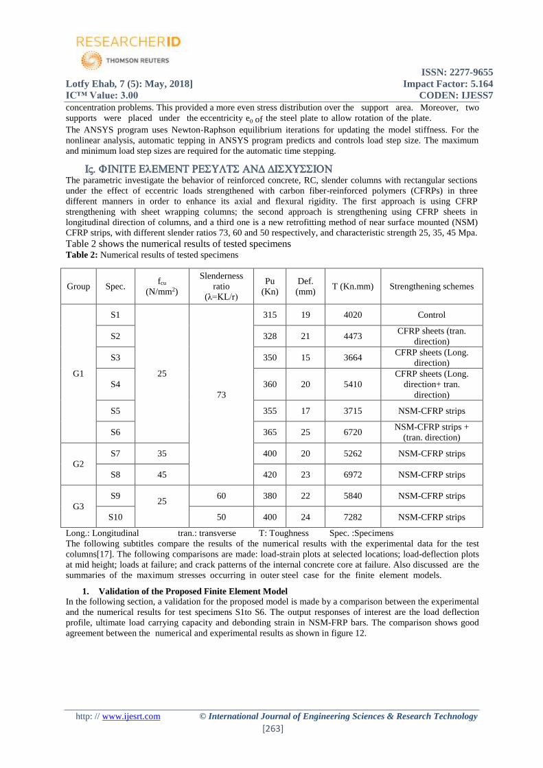
1. Validation of the Proposed Finite Element Model
In the following section, a validation for the proposed model is made by a comparison between the experimental
and the numerical results for test specimens S1to S6. The output responses of interest are the load deflection
profile, ultimate load carrying capacity and debonding strain in NSM-FRP bars. The comparison shows good
agreement between the numerical and experimental results as shown in figure 12.
ISSN: 2277-9655
Lotfy Ehab, 7 (5): May, 2018] Impact Factor: 5.164
IC™ Value: 3.00 CODEN: IJESS7
http: // www.ijesrt.com © International Journal of Engineering Sciences & Research Technology
[264]
Figure 12: The numerical and experimental load-deformation curve of tested columns
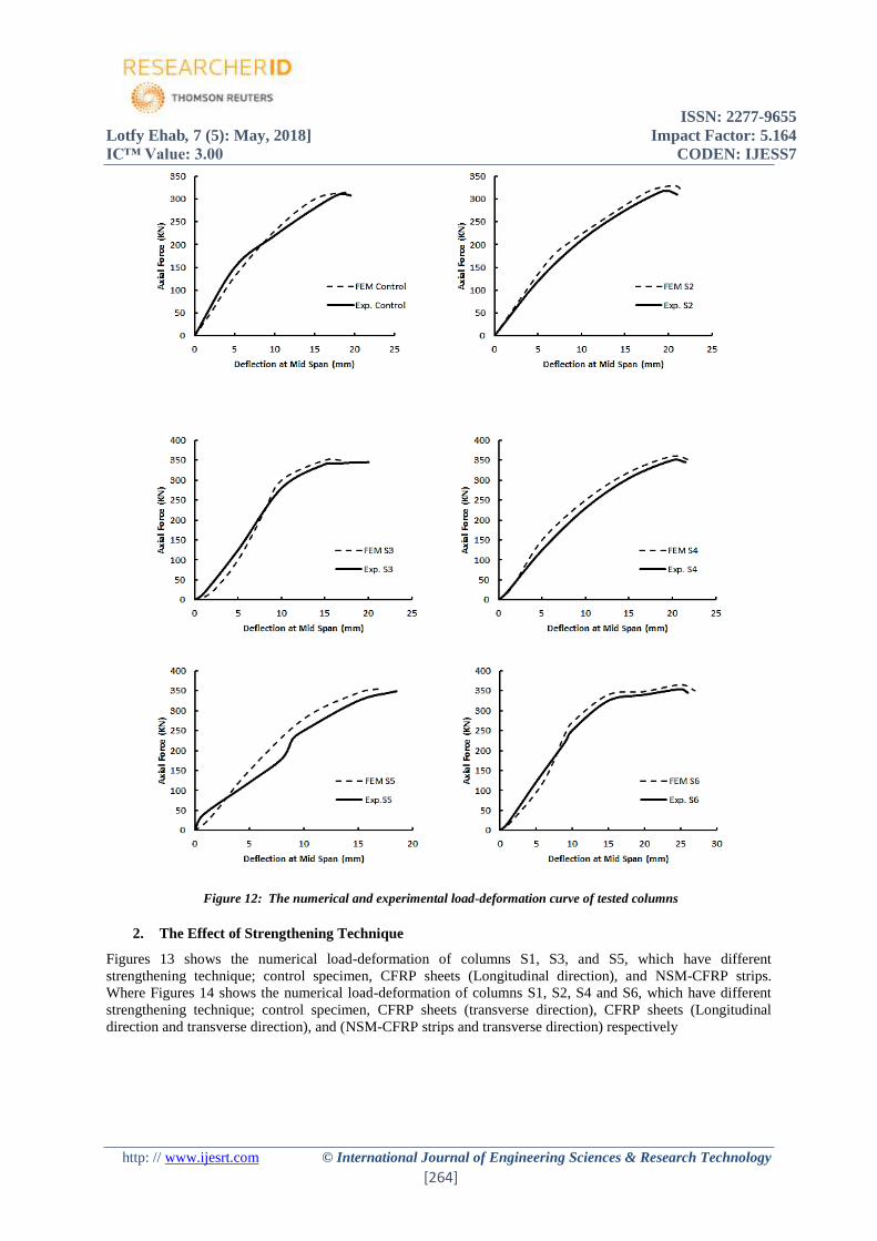
2. The Effect of Strengthening Technique
Figures 13 shows the numerical load-deformation of columns S1, S3, and S5, which have different
strengthening technique; control specimen, CFRP sheets (Longitudinal direction), and NSM-CFRP strips.
Where Figures 14 shows the numerical load-deformation of columns S1, S2, S4 and S6, which have different
strengthening technique; control specimen, CFRP sheets (transverse direction), CFRP sheets (Longitudinal
direction and transverse direction), and (NSM-CFRP strips and transverse direction) respectively
ISSN: 2277-9655
Lotfy Ehab, 7 (5): May, 2018] Impact Factor: 5.164
IC™ Value: 3.00 CODEN: IJESS7
http: // www.ijesrt.com © International Journal of Engineering Sciences & Research Technology
[265]
Figures 13: Numerical load-deformation of columns S1,
S3, and S5
Figures 14: Numerical load-deformation of columns S1,
S3, and S5
From Table 2, it can be seen that, ultimate loads and maximum deflection of S2, S3, S4, S5 and S6 to S1 are
(104,111, 114, 113 and 116%) and (111, 79, 105, 89 and 132%) respectively as shown in figures 15, 16.
Figure 15: Different strengthening technique and
ultimate load of control specimens
Figure 16: Different strengthening technique and
maximum deflection of control specimens
Using CFRP sheets (Longitudinal direction), and NSM-CFRP strips increase the ultimate loads of specimens by
111 and 113% of control specimens, where using CFRP sheets (transverse direction) with Longitudinal direction
and NSM-CFRP strips increase the maximum deflection by 105 and 132%
Using longitudinal NSM-CFRP strips tend to be more effective to prevent eventual debonding of CFRP strips
in compression and to ensure the stability of the epoxy adhesive
The most efficient strengthening m e t h o d for improving flexural capacity has been demonstrated
experimentally by a combination of the NSM-CFRP reinforcement and the CFRP wrapping.
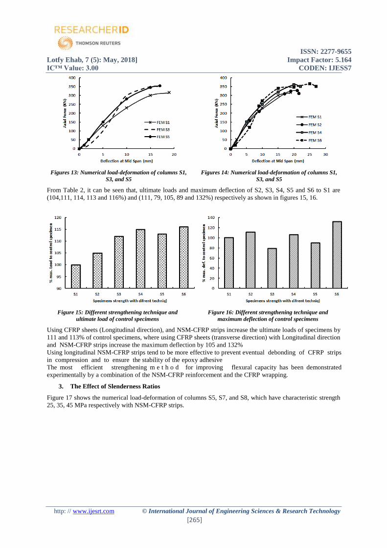
3. The Effect of Slenderness Ratios
Figure 17 shows the numerical load-deformation of columns S5, S7, and S8, which have characteristic strength
25, 35, 45 MPa respectively with NSM-CFRP strips.
ISSN: 2277-9655
Lotfy Ehab, 7 (5): May, 2018] Impact Factor: 5.164
IC™ Value: 3.00 CODEN: IJESS7
http: // www.ijesrt.com © International Journal of Engineering Sciences & Research Technology
[266]
Figure 17: Numerical load-deformation of columns S5, S7, and S8
From Table 2, it can be seen that, ultimate loads, maximum deflection and toughness of S7and S8 and S5 are
(113 and 118%), (118 and 135%) and (181 and 142%) respectively.
Using NSM-CFRP strips in strengthen specimens with characteristic strength (fcu= 45 MPa) has a significant
effect in the behavior of specimens more than specimens with characteristic strength (fcu= 25 and 35 MPa).
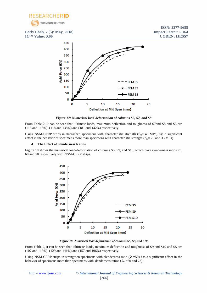
4. The Effect of Slenderness Ratios
Figure 18 shows the numerical load-deformation of columns S5, S9, and S10, which have slenderness ratios 73,
60 and 50 respectively with NSM-CFRP strips.
Figure 18: Numerical load-deformation of columns S5, S9, and S10
From Table 2, it can be seen that, ultimate loads, maximum deflection and toughness of S9 and S10 and S5 are
(107 and 113%), (129 and 141%) and (157 and 196%) respectively.
Using NSM-CFRP strips in strengthen specimens with slenderness ratio (λ=50) has a significant effect in the
behavior of specimens more than specimens with slenderness ratios (λ =60 and 73).
ISSN: 2277-9655
Lotfy Ehab, 7 (5): May, 2018] Impact Factor: 5.164
IC™ Value: 3.00 CODEN: IJESS7
http: // www.ijesrt.com © International Journal of Engineering Sciences & Research Technology
[267]
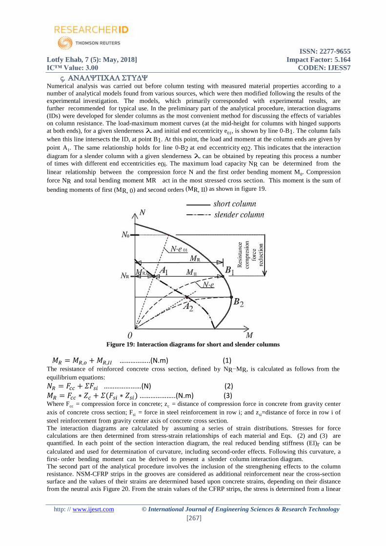
Numerical analysis was carried out before column testing with measured material properties according to a
number of analytical models found from various sources, which were then modified following the results of the
experimental investigation. The models, which primarily corresponded with experimental results, are
further recommended for typical use. In the preliminary part of the analytical procedure, interaction diagrams
(IDs) were developed for slender columns as the most convenient method for discussing the effects of variables
on column resistance. The load-maximum moment curves (at the mid-height for columns with hinged supports
at both ends), for a given slenderness λ and initial end eccentricity e01, is shown by line 0-B1. The column fails
when this line intersects the ID, at point B1. At this point, the load and moment at the column ends are given by
point A1. The same relationship holds for line 0-B2 at end eccentricity e02. This indicates that the interaction
diagram for a slender column with a given slenderness λ can be obtained by repeating this process a number
of times with different end eccentricities e0i. The maximum load capacity NR can be determined from the
linear relationship between the compression force N and the first order bending moment M0. Compression
force NR and total bending moment MR act in the most stressed cross section. This moment is the sum of
bending moments of first (MR, 0) and second orders (MR, II) as shown in figure 19.
Figure 19: Interaction diagrams for short and slender columns
𝑀𝑅 = 𝑀𝑅,𝑜 + 𝑀𝑅,𝐼𝐼 ……………..(N.m) (1) The resistance of reinforced concrete cross section, defined by NR−MR, is calculated as follows from the
equilibrium equations:
𝑁𝑅 = 𝐹𝑐𝑐 + 𝛴𝐹𝑠𝑖 …………………(N) (2) 𝑀𝑅 = 𝐹𝑐𝑐 ∗ 𝑍𝑐 + 𝛴(𝐹𝑠𝑖 ∗ 𝑍𝑠𝑖) ………………..(N.m) (3) Where Fcc = compression force in concrete; zc = distance of compression force in concrete from gravity center
axis of concrete cross section; Fsi = force in steel reinforcement in row i; and zsi=distance of force in row i of
steel reinforcement from gravity center axis of concrete cross section.
The interaction diagrams are calculated by assuming a series of strain distributions. Stresses for force
calculations are then determined from stress-strain relationships of each material and Eqs. (2) and (3) are
quantified. In each point of the section interaction diagram, the real reduced bending stiffness (EI)r can be
calculated and used for determination of curvature, including second-order effects. Following this curvature, a
first- order bending moment can be derived to present a slender column interaction diagram.
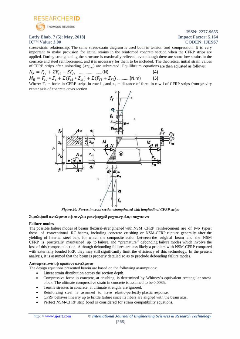
The second part of the analytical procedure involves the inclusion of the strengthening effects to the column
resistance. NSM-CFRP strips in the grooves are considered as additional reinforcement near the cross-section
surface and the values of their strains are determined based upon concrete strains, depending on their distance
from the neutral axis Figure 20. From the strain values of the CFRP strips, the stress is determined from a linear
ISSN: 2277-9655
Lotfy Ehab, 7 (5): May, 2018] Impact Factor: 5.164
IC™ Value: 3.00 CODEN: IJESS7
http: // www.ijesrt.com © International Journal of Engineering Sciences & Research Technology
[268]
stress-strain relationship. The same stress-strain diagram is used both in tension and compression. It is very
important to make provision for initial strains in the reinforced concrete section when the CFRP strips are
applied. During strengthening the structure is maximally relieved, even though there are some low strains in the
concrete and steel reinforcement, and it is necessary for them to be included. The theoretical initial strain values
of CFRP strips after unloading (εf,un) are subtracted. Equilibrium equations are then adjusted as follows:
𝑁𝑅 = 𝐹𝑐𝑐 + 𝛴𝐹𝑠𝑖 + 𝛴𝐹𝑓𝑖 …………………(N) (4)
𝑀𝑅 = 𝐹𝑐𝑐 ∗ 𝑍𝑐 + 𝛴(𝐹𝑠𝑖 ∗ 𝑍𝑠𝑖) + 𝛴(𝐹𝑓𝑖 + 𝑍𝑓𝑖) ………..(N.m) (5) Where: Ffi = force in CFRP strips in row i , and zfi = distance of force in row i of CFRP strips from gravity
center axis of concrete cross section
Figure 20: Forces in cross section strengthened with longitudinal CFRP strips
Failure modes
The possible failure modes of beams flexural-strengthened with NSM CFRP reinforcement are of two types:
those of conventional RC beams, including concrete crushing or NSM-CFRP rupture generally after the
yielding of internal steel bars, for which the composite action between the original beam and the NSM
CFRP is practically maintained up to failure, and ‘‘premature’’ debonding failure modes which involve the
loss of this composite action. Although debonding failures are less likely a problem with NSM-CFRP compared
with externally bonded FRP, they may still significantly limit the efficiency of this technology. In the present
analysis, it is assumed that the beam is properly detailed so as to preclude debonding failure modes.
The design equations presented herein are based on the following assumptions:
Linear strain distribution across the section depth.
Compressive force in concrete, at crushing, is determined by Whitney’s equivalent rectangular stress
block. The ultimate compressive strain in concrete is assumed to be 0.0035.
Tensile stresses in concrete, at ultimate strength, are ignored.
Reinforcing steel is assumed to have elastic-perfectly plastic response.
CFRP behaves linearly up to brittle failure since its fibers are aligned with the beam axis.
Perfect NSM-CFRP strip bond is considered for strain compatibility equations.
ISSN: 2277-9655
Lotfy Ehab, 7 (5): May, 2018] Impact Factor: 5.164
IC™ Value: 3.00 CODEN: IJESS7
http: // www.ijesrt.com © International Journal of Engineering Sciences & Research Technology
[269]
The governing failure mode is concrete crushing, preceded by steel yielding, prior to CFRP rupture.
A minimum NSM-CFRP ratio is formulated to ensure this failure mode.
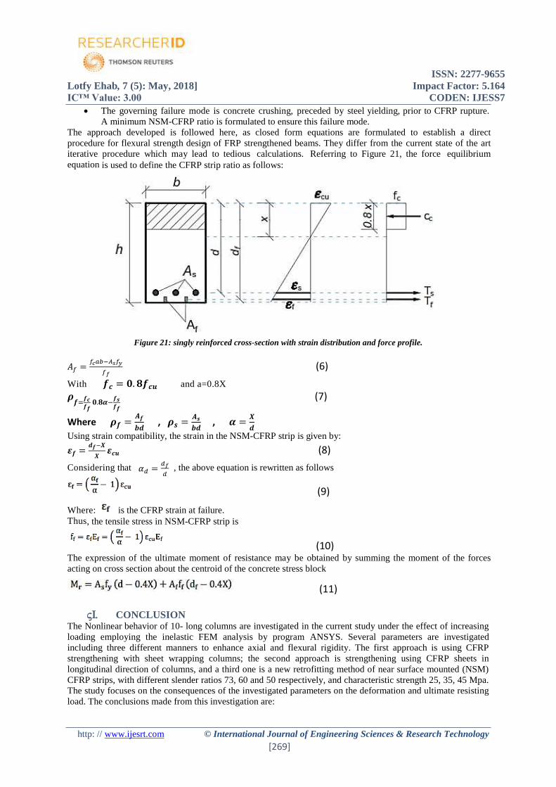
The approach developed is followed here, as closed form equations are formulated to establish a direct
procedure for flexural strength design of FRP strengthened beams. They differ from the current state of the art
iterative procedure which may lead to tedious calculations. Referring to Figure 21, the force equilibrium
equation is used to define the CFRP strip ratio as follows:
Figure 21: singly reinforced cross-section with strain distribution and force profile.
𝐴𝑓 =𝑓𝑐𝑎𝑏−𝐴𝑠𝑓𝑦
𝑓𝑓 (6)
With 𝒇𝒄 = 𝟎. 𝟖𝒇𝒄𝒖 and a=0.8X
𝝆𝒇=
𝒇𝒄𝒇𝒇
𝟎.𝟖𝜶−𝒇𝒔𝒇𝒇
(7)
Where 𝝆𝒇 =𝑨𝒇
𝒃𝒅 , 𝝆𝒔 =
𝑨𝒔
𝒃𝒅 , 𝜶 =
𝑿
𝒅
Using strain compatibility, the strain in the NSM-CFRP strip is given by:
𝜺𝒇 =𝒅𝒇−𝑿
𝑿𝜺𝒄𝒖 (8)
Considering that 𝛼𝑑 =𝑑𝑓
𝑑 , the above equation is rewritten as follows
(9)
Where: is the CFRP strain at failure. Thus, the tensile stress in NSM-CFRP strip is
(10) The expression of the ultimate moment of resistance may be obtained by summing the moment of the forces
acting on cross section about the centroid of the concrete stress block
(11)
CONCLUSION The Nonlinear behavior of 10- long columns are investigated in the current study under the effect of increasing
loading employing the inelastic FEM analysis by program ANSYS. Several parameters are investigated
including three different manners to enhance axial and flexural rigidity. The first approach is using CFRP
strengthening with sheet wrapping columns; the second approach is strengthening using CFRP sheets in
longitudinal direction of columns, and a third one is a new retrofitting method of near surface mounted (NSM)
CFRP strips, with different slender ratios 73, 60 and 50 respectively, and characteristic strength 25, 35, 45 Mpa.
The study focuses on the consequences of the investigated parameters on the deformation and ultimate resisting
load. The conclusions made from this investigation are:
ISSN: 2277-9655
Lotfy Ehab, 7 (5): May, 2018] Impact Factor: 5.164
IC™ Value: 3.00 CODEN: IJESS7
http: // www.ijesrt.com © International Journal of Engineering Sciences & Research Technology
[270]
Using longitudinal direction CFRP sheets and NSM-CFRP strips increase the ultimate loads of specimens
by 111 and 113% of control specimens.
Using transverse direction CFRP sheets with longitudinal direction and NSM-CFRP strips increase the
maximum deflection by 105 and 132%
Using longitudinal NSM-CFRP strips tend to be more effective to prevent eventual debonding of CFRP
strips in compression and to ensure the stability of the epoxy adhesive
The NSM- CFRP strips embedded longitudinally works effectively in tension which takes place at the
minor bending axis of the slender columns where the second order (buckling) effect takes place results in
an increase in the bending moment at the same compression force value. The most efficient strengthening m e t h o d for improving flexural capacity has been demonstrated
experimentally by a combination of the NSM-CFRP reinforcement and the CFRP wrapping. Using NSM-CFRP strips in strengthen specimens with characteristic strength (fcu= 45 MPa) has a
significant effect in the behavior of specimens more than specimens with characteristic strength (fcu= 25
and 35 MPa).
Using NSM-CFRP strips in strengthen specimens with slenderness ratio (λ=50) has a significant effect in
the behavior of specimens more than specimens with slenderness ratios (λ =60 and 73).
Simplified analysis of singly reinforced rectangular sections with NSM-CFRP strips:
The expression of the ultimate moment of resistance may be obtained by summing the moment of the
forces acting on cross section about the centroid of the concrete stress block
𝜺𝒇 =𝒅𝒇−𝑿
𝑿𝜺𝒄𝒖
Where: is the CFRP strain at failure.
REFERENCES [1] Yazici, V., “Strengthening hollow reinforced concrete columns with fibre reinforced polymers” Doctor
of Philosophy thesis, School of Civil, Mining and Environmental Engineering, University of
Wollongong, 2012.
[2] McShane, I., “Social value and the management of community infrastructure” Australian Journal of
Public Administration, 2006. 65(4): p. 82-96.
[3] Marshall Jr, O., R. Lampo, and J. Busel. “IN-PLACE STRENGTHENING, REPAIR OR UPGRADE
OF CONCRETE CIVIL ENGINEERING STRUCTURES USING FIBER REINFORCED
POLYMERIC COMPOSITE MATERIALS” First International Conference on Composites in
Infrastructure. 1996.
[4] Lam, L. and J. Teng, “Design-oriented stress-strain model for FRP-confined concrete in rectangular
columns”. Journal of Reinforced Plastics and Composites, 2003. 22(13): p. 1149-1186.
[5] Priestley, M.N., F. Seible, and G.M. Calvi, “Seismic design and retrofit of bridges” John Wiley & Sons,
New York, 686 p, 1996.
[6] Mirmiran A., M. Shahawy, and T. Beitleman, Slenderness limit for hybrid FRP- concrete columns.
Journal of Composites for Construction, 2001. 5(1): p. 26-34.
[7] Jiang, T., “FRP-confined RC columns: analysis, behavior and design” Ph.D. thesis, The Hong
Kong Polytechnic University, Hong Kong, China The Hong Kong Polytechnic University,2008.
[8] Teng JG, Chen JF, Smith ST,Lam L (2002) FRP: strengthened RC structures. Frontiers in Physics, p:
266.
[9] Hassan T. and S. Rizkalla, “Investigation of bond in concrete structures strengthened with near surface
mounted carbon fiber reinforced polymer strips”. Journal of composites for construction, 2003. 7(3): p.
248-257.
[10] De Lorenzis, L., B. Miller, and A. Nanni, “Bond of FRP laminates to concrete”. ACI Materials
Journal, 2001. 98(3): p. 256-264.
ISSN: 2277-9655
Lotfy Ehab, 7 (5): May, 2018] Impact Factor: 5.164
IC™ Value: 3.00 CODEN: IJESS7
http: // www.ijesrt.com © International Journal of Engineering Sciences & Research Technology
[271]
[11] Micelli, F. and A. Nanni, “Durability of FRP rods for concrete structures” Construction and Building
materials, 2004. 18(7): p. 491-503.
[12] Hassan, T. and S. Rizkalla, “Bond mechanism of NSM FRP bars for flexural strengthening of
concrete structures”. ACI Structural Journal, 2004. 101(6): p. 830-839.
[13] Aad, G., “The ATLAS simulation infrastructure”. The European Physical Journal C, 2010. 70(3): p.
823-874.
[14] Hawileh, R.A., “Nonlinear finite element modeling of RC beams strengthened with NSM FRP rods”.
Construction and Building Materials, 2012. 27(1): p. 461-471.
[15] Shahawy, M., A. Mirmiran, and T. Beitelman, “Tests and modeling of carbon-wrapped concrete
columns”. Composites Part B: Engineering, 2000. 31(6): p. 471-480.
[16] Barbero, E.J., Finite element analysis of composite materials using AbaqusTM. 2013: CRC press.
[17] Selmy YASSER, Lotfy EHAB, El-Kersh IBRAHIM “BEHAVIOR OF LONG COLUMNS
STRENGTHENED BY CFRP SHEETS AND NEAR SURFACE MOUNTED STRIPS”
INTERNATIONAL CONFERENCE ON ADVANCED CIVIL ENGINEERING AND
TRANSPORTATION, ACET, April 15-16,2018, SHANGHAI, CHINA.