Embed Size (px)
Citation preview

4 ^ Sn--vrruit Rccortis Center
SDMS DocID 444458 2ZZ OTHER lt ^ i j t | ( ^ t ^ ^
W92224D
DRAFT WORK PLAN
TECHNICAL ASSISTANCE
SOLVENTS RECOVERY SERVICE OF NEW ENGLAND INC SITE
SOUTHINGTON CONNECTICUT
HALLIBURTON NUS Environmental Corporation
EPA Work Assignment No 30-1R08 Contract No 68-W8-0117 HNUS Project No 5926
June 1992
o
^ H A L L I B U R T O N NUS ^ S Environmental Corporation T
W92224D
DRAFT WORK PLAN
TECHNICAL ASSISTANCE
SOLVENTS RECOVERY SERVICE OF NEW ENGLAND INC SITE SOUTHINGTON CONNECTICUT
HALLIBURTON NUS Environmental Corporation
EPA Work Assignment No 30-1R08 EPA Contract No 68-W8-0117
HNUS Project No 5926
June 1992
George 5jl Gardner PE Project Manager Program Manager
CONFLICT OF INTEREST CERTIFICATION
HALLIBURTON NUS Environmental Corporation certifies that to the
best of its knowledge and belief there are no relevant facts andor
circumstances that would give rise to an organizational or
individual conflict of interest in connection with this work
planwork assignment or if any facts andor circumstances would
give rise to such conflict they have been disclosed in accordance
with Contract Clause H2 ORGANIZATIONAL CONFLICTS OF INTEREST
andor Contract Clause H16 NOTIFICATION OF CONFLICT OF INTEREST
REGARDING PERSONNEL
DRAFT
TABLE OF CONTENTS DRAFT WORK PLAN
TECHNICAL ASSISTANCE SOLVENTS RECOVERY SERVICE OF NEW ENGLAND INC SITE
SOUTHINGTON CONNECTICUT
SECTION PAGE
10 INTRODUCTION 1-1
20 SITE DESCRIPTION AND BACKGROUND 2-1 21 Site Area Description 2-1 22 Site History and Contaminant Source 2-7
Identification 221 Former Features 2-8 222 Current Features 2-13
23 Site Characterization 2-16 231 Site Geology 2-17 232 Hydrogeologic Characterization 2-18 233 Nature and Extent of Contamination 2-20
30 SCOPE OF THE RAPID REMEDIAL ACTION SUPPORT 3-1 31 Task 0100 - Project Planning 3-2
311 Work Plan and Cost Estimate 3-3 Preparation
32 Task 0500 - Dewatering Evaluation 3-4 33 Task 0600 - Contaminant Assessment 3-6 34 Task 1000 - Technical Evaluations of 3-9
Alternatives 341 Soil Remediation Evaluation 3-10 342 GroundwaterVapor Remediation 3-13
Evaluation 35 Task 1100 - Engineering EvaluationCost 3-16
Analysis Report 36 Task 1200 - Post-EECA Support 3-16
361 Draft Final Design Report (90) 3-18 362 Final Design (100) 3-21 363 Rapid Remedial Action Implementation 3-22
W92224D
DRAFT
TABLE OP CONTENTS (Continued) DRAFT WORK PLAN
TECHNICAL ASSISTANCE SOLVENTS RECOVERY SERVICE OF NEW ENGLAND INC SITE
SOUTHINGTON CONNECTICUT
SECTION PAGE
40 COMMUNITY RELATIONS AND ADMINISTRATIVE RECORD 4-1 SUPPORT 41 Task 0200 - Community Relations 4-1
411 Task 0210 - Update the Community 4-1 Relations Plan
412 Task 0220 - Provide Public Meeting 4-2 Support
413 Task 0230 - Prepare a Fact Sheet 4-3 414 Task 0250 - Provide Public Hearing 4-3
Support 415 Task 0260 - Publish Public Notices 4-3 416 Task 0270 - Maintain Information 4-4
Repositories 417 Task 0290 - Prepare a Responsiveness 4-4
Summary 42 Task 1600 - Administrative Record 4-5
50 PROJECT DELIVERABLES AND SCHEDULE 5-1 51 Major Deliverables 5-1 52 Interim Deliverables 5-2 53 Project Schedule 5-2
60 PROJECT MANAGEMENT 6-1 61 Project Organization 6-1 62 Quality Assurance and Data Management 6-2 63 Cost Estimate 6-2
70 EQUIPMENT AND SUPPLIES 7-1
APPENDIX A - OPERATIONS AREA SOIL SAMPLING RESULTS APPENDIX B - GROUNDWATER SAMPLING RESULTS
W92224D 11
DRAFT
TABLE OF CONTENTS (Continued) DRAFT WORK PLAN
TECHNICAL ASSISTANCE SOLVENTS RECOVERY SERVICE OF NEW ENGLAND INC SITE
SOUTHINGTON CONNECTICUT
TABLES
NUMBER PAGE
2-1 RANGE OF DETECTED CONTAMINANTS 2-23 3-1 EECA REPORT OUTLINE 3-17
FIGURES
N U M B E R PAGE
2-- 1 (GENERAL SITE LOCATION 2-2 2--2 1STUDY AREA 2-3 2--3 FORMER OPERATIONS AREA FEATURES 2-9 2--4 ICURRENT OPERATIONS AREA FEATURES 2-14 2-- 5 1OPERATIONS AREA VOCs IN SOIL 2-26 2--6 VOCs IN OVERBURDEN AQUIFER 2-28 2--7 VOCs IN BEDROCK AQUIFER 2-29 5--1 PROJECT SCHEDULE 5-3 6--1 PROJECT ORGANIZATION 6-3
W92224D iii
1
10
DRAFT
INTRODUCTION
At the request of the US Environmental Protection Agency (EPA)
Region I HALLIBURTON NUS Environmental Corporation (HNUS) will
provide technical assistance for a rapid remedial action at the
Solvents Recovery Service of New England Inc (SRSNE) site in
Southington Connecticut This technical assistance involves the
performance of an Engineering EvaluationCost Analysis (EECA) to
evaluate rapid remedial action alternatives and preparation of an
EECA Report The technical assistance also involves provision of
community relations and administrative record support and design
and implementation of the selected rapid remedial action This
Work Plan was developed based on the EPA Statement of Work (SOW)
dated April 24 1992 the scoping meeting of June 4 1992 and the
results of discussions with the RPM The work was authorized under
Work Assignment Number 30-1R08
HNUS understands that the overall objective of the rapid remedial
action at the SRSNE site is to accelerate the site remediation
process and control the migration of contaminants through mass
removal of known contaminants from soils and groundwater To
achieve this overall objective EPAs specific goals are to
accomplish the following
W92224D 1-1
DRAFT
1 Dewater the Operations Area or portions of the Operations
Area as appropriate to allow work to proceed on the
contaminated soils
2 Initiate removal of Volatile Organic Compounds (VOCs)
from soils through in-situ treatment and
3 Install and operate an appropriate water treatment system
that does not result in unacceptable air emissions This
water treatment system will be designed to address
contaminated groundwater and potential vapors which may
be generated from dewatering and treatment of the soil
An EECA is required to provide the EPA with the necessary
technical cost and risk information to develop evaluate and
select the most appropriate options for fulfilling each of these
objectives An EECA Report records this comparative analytical
process and is required for a rapid remedial (non-time-critical
removal) action
This Technical Assistance Work Assignment will be performed
consistent with the requirements of the following documents the
National Contingency Plan (NCP) the Comprehensive Environmental
Response Compensation and Liability Act (CERCLA) of 1980 as
amended by the Superfund Amendments and Reauthorization Act (SARA)
W92224D 1-2
DRAFT
of 1986 and the EPA SOW HNUS will utilize to the extent
appropriate the Draft Engineering EvaluationCost Analysis
Guidance for Non-Time-Critical Removal Actions (June 1987) the
revised Outline of EECA Guidance (March 30 1988) The Role
of Expedited Response Actions Under SARA (April 21 1987) (OSWER
Directive 93600-15) and other information and guidance on
conducting rapid remedial actions which EPA provides in writing
during the period of this assignment At the direction of the RPM
the contractor will also consult with experts in the Environmental
Services Division in EPA Region I and in the Emergency Response
Division within the Office of Emergency and Remedial Response for
assistance in planning and preparing the EECA and in implementing
the rapid remedial action
This Work Plan presents the technical scope of work and proposed
schedule for preparing the EECA and providing community relations
and administrative record support It addresses the initial design
of the rapid remedial action but does not address implementation
of the rapid remedial action which may be the subject of an
amended SOW and a subsequent amendment to this work plan This
Draft Work Plan contains seven sections Section 10 provides an
introduction Section 20 summarizes the site history and existing
site data Section 30 details the tasks to be undertaken in the
analysis of rapid remedial action alternatives and in the
preparation of a draft EECA Report Section 40 describes the
bullraquolaquo W92224D 1-3
DRAFT
tasks to be undertaken to support the community relations and
administrative record requirements of the EECA process Section
50 describes anticipated interim deliverables and the schedule for
the work Section 60 provides a proposed project management
approach and Section 70 identifies the equipment and consumable
supplies that may be required to perform the activities identified
in the Draft Work Plan
W92224D 1-4
DRAFT
20 SITE DESCRIPTION AND BACKGROUND
A summary of the site area history and physical and chemical
characterization is provided in the following text
21 Site Area Description
The Solvents Recovery Service of New England (SRSNE) National
Priorities List (NPL) Superfund site is located on Lazy Lane in the
Town of Southington Connecticut in Hartford County approximately
15 miles southwest of Hartford Figure 2-1 shows the general
location of the SRSNE Inc facility (Operations Area) with respect
to the Town of Southington and its environs The NPL study area
(Figure 2-2) for the SRSNE facility includes the adjoining property
to the east known as the former Cianci property the Town of
Southington well field and the lot formerly occupied by the Queen
Street Diner on the eastern side of the Quinnipiac River The
EECA analysis and subsequent removal action will for the most part
be confined to the Operations Area itself
W92224D 2-1
DRAFT
000 r c r
SOURCE US OEOLOOICAL SURVEY 75 MINUTE SERIES TOFOORAFHIC MAPS CONNECHCUT QUADRANOLES
(SOUTHINGTON 196S PHCTTOREVISED 19lt4 MERIDEN 1967PR 19M NEW BRITAIN 1966 PR 1984 B R i n O L 1966 FT 1984)
FIGURE 2-1 CONNEQICUT
LOCATION MAP SOLVENTS RECOVERY SERVICE OF NEW ENGLAND INC SITE
SOUTHINGTON CONNECTICUT OUAORANGtX LOCATION
2 -2 W92224D
DRAFT
SOLVENTS RECOVERY SERVICEshyOF NEW ENGLAND INC
LEGEND SRSNE PROPERTY UNE
bulllaquoKlaquo^
APPROXIMATC SCALE IN FEET FIGURE 2-2 STUDY AREA MAP
SRSNE INC SITE AND TOWN PRODUCTION WELLS SOUTHINGTON CONNECTICUT
DRAFT
SRSNE Operations Area - The Operations Area occupies approximately
25 acres and consists of the grounds and structures within the
fenced perimeter where the day-to-day drum storage and fuel
blending operations were conducted prior to April 1991 The lot
owned by SRSNE occupies 37 acres and includes the Operations Area
and the access road leading to Lazy Lane
The Operations Area is located in the Quinnipiac River basin
approximately 600 feet west of the river channel This lot is
situated just south of Lazy Lane and the Mickeys Garage property
The ground surface elevation ranges between approximately 164 and
180 feet above mean sea level (MSL) The majority of the
Operations Area where day-to-day activities occurred is level (166
- 168 feet MSL) A steep hill (maximum elevation of 180 feet MSL)
occupies the west and southwest portions of the property
Just to the east of the Operations Area outside of the chain-link
fence is an unlined drainage ditch which carries treated effluent
from the cooling towerair stripper to the Quinnipiac River
West of the Operations Area - Immediately uphill and west of the
SRSNE Operations Area is the S Yorski property which has a house
and several tracts of land used for farming Only private
residences are situated farther west of the Yorski property A
number of private residences are located to the southwest of the
W92224D 2-4 ~ bull
DRAFT
Study area in the vicinity of Curtiss Street and in the upland
areas
To the west the ground surface elevation increases steadily to a
maximum of 280 feet MSL along Lazy Lane approximately 2200 feet
west of the Operations Area
North of the Operations Area - Immediately north of the SRSNE
Operations Area is the Mickeys Garage auto body repair shop
located on Lazy Lane Several tracts of undeveloped land and two
ponds are located north of Lazy Lane This area extends
approximately to Interstate Highway 1-84 One private residence is
situated northeast of the Operations Area across from the former
Cianci property
North of the study area the Quinnipiac River channel turns
northwest (the river flows from north to south) and passes under Ishy
84 This area is generally in the 150-170 foot MSL elevation
range One ridge possibly a former roadway rises to a peak
elevation of 180 feet MSL (approximately 300 feet north of Lazy
Lane)
East of the Operations Area - The SRSNE facility is bordered on the
east by the Boston amp Maine (BampM) right-of-way and the former Cianci
property The Quinnipiac River borders the eastern edge of the
W92224D 2-5
DRAFT
former Cianci property The former Cianci property currently
owned by SRSNE has never been developed and has been altered by
past earth moving and leveling activities Wetlands which occupied
this area have been filled Some wetlands remain as do those in
the floodplain of the Quinnipiac River An unpaved access road
traverses from north to south through the Cianci property and into
the Town well field property
The Cianci property is a well-vegetated level lot characterized by
open grassy fields and some wetlands Surface elevations range
from 150 feet MSL (at the floodplain) to about 160 feet MSL near
the BampM railroad tracks
A number of commercial operations including auto body and repair
shops gasoline stations stores and restaurants are located on
Route 10 (Queen Street) due east of the Quinnipiac River Route 10
serves as a major thoroughfare through the Town of Southington
Residential dwellings are situated uphill and east of Queen Street
The ground elevation increases east of Queen Street to
approximately 250 to 300 feet MSL
South of the Operations Area - Due south of the former Cianci
property and southeast of the Operations Area is the Town of
Southington well field property which consists of approximately
282 acres of undeveloped land Town Production Wells Nos 4 and
W92224D 2-6
22
DRAFT
6 are located approximately 2000 and 1400 feet south of the SRSNE
property respectively The Quinnipiac River flows southward along
the eastern edge of the former Cianci property and a portion of the
Town well field and between Wells 4 and 6
The Town well field is characterized by open grassy fields in
gently rolling terrain Wetlands are present in the proximity of
the River Ground elevations range between 145 feet MSL (in the
floodplain near Well No 6) to 160 feet MSL at the peak of one
hill A seasonal pondwetland occupies an area encompassing
portions of the Cianci property and the north portion of the Town
well field A Connecticut Light amp Power (CLampP) easement for a high
tension electric transmission line is located in the northern
portion of the Town well field property (in a northwest-southeast
orientation)
Site History and Contaminant Source Identification
SRSNE Inc began operations in Southington in 1955 The facility
received spent industrial solvents which were distilled for reuse
as solvents or blended with fuel oil for use as a hazardous fuel
product The facility was permanently closed in May 1991
W92224D 2-7
DRAFT
While the SRSNE Inc facility operated various practices resulted
in the discharge of spent solvents into the soils and groundwater
These practices included disposing distillation sludges in unlined
lagoons burning sludges in an open-pit and spilling spent
solvents during handling storage and loading activities within
the Operations Area The remainder of this section presents a
summary of the potential contaminant source areas in the Operations
Area Both former (pre-1980) and current (post-1980) facility
features are presented
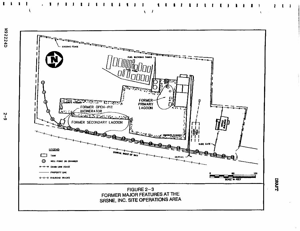
221 Former Features
Some of the historical information for the contaminant source areas
is based on an interpretation of one set of aerial photographs by
the EPA Environmental Photographic Interpretation Center (EPIC)
(1988) Information developed by other investigators was used to
supplement the interpretation of the aerial photographs Figure 2shy
3 presents the former features described in this section
Operations Building - The 1951 and 1957 aerial photographs of the
area show the concrete block operations building Three
distillation pots and a distillation column were located adjacent
to the operations building in the process area These facilities
were used to separate recoverable fractions from the spent
solvents Aqueous wastes from the distillation process were
W92224D 2-8
I i E I 1 f I f I i f 1 i i 1 1 t I I I i I I 1 I i I i I I I I I
LEGEND
I I TANK raquoraquo laquocw
Q ) MEll POWT CR CHAUaU
-raquomdashlaquomdashraquoshy CHAM UNK f lNCt
PROPMTY UNC UO
H 1 h RANJIOAO IRACXS SCMC M TOT
FIGURE 2-3 FORMER MAJOR FEATURES AT THE
SRSNE INC SITE OPERATIONS AREA
DRAFT
discharged to an unspecified on-site location(s) Still bottom
sludges were discharged into two unlined lagoons discussed below
(EPA FIT EampE 1980)
Primary and Secondary Lagoons - These lagoons apparently installed
after 1957 were first identified in an April 1965 aerial
photograph The primary lagoon was located immediately south of
the operations building The secondary lagoon (which appears to be
two earthen excavations separated by a berm) was located 120 feet
south-southeast of the operations building Both lagoons are no
longer present having been covered with soil
The facility disposed of distillation bottoms in the primary lagoon
situated adjacent to the process area Overflow from the primary
lagoon was directed to the secondary lagoon Overflow from the
secondary lagoon would flow to the drainage ditch adjacent to the
railroad tracks and subsequently into the Cianci property (EPA FIT
E amp E 1980)
Open Pit Incinerator - The 1967 photograph showed a walled open
pit located in the southeastern corner of the property This pit
was present in the 1970 1975 1980 and 1982 aerial photographs of
the study area The still bottoms were burned in the open pit
after disposal in the lagoons stopped This open burning practice
was discontinued some time in the late 1960s or early 1970s
W92224D 2-10
DRAFT
In the 1975 photograph the EPIC analysis indicated that a tank
truck was parked adjacent to the pit where it appeared to discharge
its contents A large pool of liquid is visible at the
northeastern corner of the pit draining into the ditch paralleling
the railroad tracks
Tank Farm - The 1965 aerial photograph indicated the presence of
three horizontal tanks south of the operations building and the
primary lagoon A retaining wall was visible in the 1975
photograph By 1980 there were 19 tanks in the tank farm This
tank farm was located in the western part of the property on the
slope of the hill Five vertical tanks were also identified
adjacent to the operations building in the 1982 photograph
Drum Storage Pad - Drums were first identified in the 1965
photograph Later photos (taken in 1970 1975 1980 and 1982)
indicate that the property was used extensively with numerous 55shy
gallon drums stationary tanks and tank trailers distributed
throughout While these later photos show no obvious stains or
pools of liquid there were no secondary containment structures
visible around the drum or trailer storage areas to collect leaking
materials
W92224D 2-11
DRAFT
Septic Leach Field - The leaching field was not shown on the aerial
photographs although records indicate that one existed for the
sanitary facilities located in the operations building This
leaching field was located to the east of the operations building
and was likely installed after the operations building was
constructed The CT DEP identified the presence of VOCs in samples
collected from the leach field The CT DEP also theorized that
spent solvents may have been disposed of in the septic system
General - The aerial photographs indicated that during the site
development the terrain was altered from a sloping land area to a
flat parking and storage area with a steeply cut embankment It is
apparent from the present terrain of the site that a substantial
volume of soil was excavated and removed from the property to
accommodate such a large flat surface Surface drainage from the
site appeared to flow to the east into the drainage ditch along
the railroad bed and through the culvert to the former Cianci
property The 1970 photograph showed an unpaved access road that
lead to the northwestern corner of the Operations Area The 1975
photograph showed that access to the facility was through a roadway
leading to the northeastern corner of the property parallel to the
railroad tracks The 1982 photograph identified the presence of a
security fence encircling the perimeter of the facility
W92224D 2-12
DRAFT
^ 222 Current Features
Since 1980 SRSNE made modifications to the facility structures
Figure 2-4 depicts the structures and features that remain at the
Operations Area
Office Trailer - An office trailer with a false foundation was
erected during the mid-1980s It is located inside the first
electric gate A second electric slide gate controls access into
the Operations Area The security fences and gates are intact and
in good condition A small parking area abutting the office
trailer was paved The entire truck parking and transfer area
within the Operations Area was paved with asphalt in early 1990
Operations Building - The operations building houses a warehouse
area a mechanical room with a large boiler the cooling towerair
stripper an office and a worker rest area
Tank Farm - The tank farm has four horizontal tanks remaining and
is protected by a concrete containment berm Two vertical blending
tanks are located in the process area adjacent to the operations
building A small sheet metal shed was constructed between the
operations building and the blending tanks drums were opened and
processed at this location
W92224D 2-13
vo
M
a
lECUlU
0 EIlHACnOH raquolaquou
HI bull shy bull CIIAItl UNK FENCf
| I I RAtROAO IRACKS
tvgt
--^-laquolaquoa^) f ^ RIQI
scAu M n t t
FIGURE 2-4 oCURRENT FEATURES AT THE
SRSNE INC SITE OPERATIONS AREA
^ bull i I l l l i l i l t l l l i f l l l l l f l l l l l I I
DRAFT
Drum Storage Area - Two drum storage areas were constructed with
coated concrete containments and a spill collection system
Following cessation of facility activities all drums were removed
from the property
Open Pit Incinerator - The open pit was removed from service during
the late-1960s and early-1970s even though the structure remained
at the Operations Area through 1982 (as seen in aerial
photographs) Following that time the open pit was dismantled and
the foundation was covered
On-site Interceptor System - This system was installed in 1985
along the southern and eastern perimeter of the property This
system consists of 25 extraction wells which pump groundwater to
the cooling towerair stripper on the roof of the operations
building The groundwater is air stripped of volatile organic
compounds (VOCs) and the treated effluent is discharged to a buried
pipe and then into an unlined drainage ditch The effluent crosses
under the railroad tracks through a culvert enters a second buried
culvert in the former Cianci property and exits to the Quinnipiac
River The cooling tower VOC emissions are discharged to the
atmosphere In 1989 three additional extraction wells were
installed to compensate for the lack of performance of the original
system This system remains in operation
W92224D 2-15
23
DRAFT
General - The fuel and chemical piping and valve systems are still
connected to the tanks on the site Chemical residue may still be
present in these pipes
The hillsides on the western portions of the Operations Area are
covered with 2-3 inches of crushed stone There is a knoll on the
southwestern corner of the property which is vegetated with small
trees and brush A small quantity of construction debris was
deposited in this area by SRSNE when the facility was active The
debris remains on-site
Site Characterization
This section describes the site conditions based on information
provided to date through the Remedial Investigation (RI) process
This characterization centers around the Operations Area and
includes a description of the geologic and hydrogeologic setting
and well as the nature and extent of known contamination A more
detailed discussion of the known site characteristics may be found
in the SRSNE Phase 2 Technical Memorandum Remedial Investigation
Feasibility Study (HNUS June 1992)
W92224D 2-16
DRAFT
231 Site Geology
The geology underlying the study area consists of three distinct
units
o Stratified outwash deposits consisting of interbeds of
thin silt silty sand and sand layers These units
underlie approximately 90 percent of the study area The
water table aquifer downgradient of the Operations Area
is located in these stratified deposits The groundwater
and accompanying contaminants migrate through these
deposits to the east and southeast of the Operations
Area
o Basal till consisting of an unstratified poorly sorted
mix of clay silt sand gravel cobbles and boulders
The till varies in thickness and is absent in several
locations within the study area Where the till is
present it may act as a semi-confining layer to
groundwater flow between the more permeable overlying
soils and the bedrock aquifer Till windows allow direct
communication of groundwater from one aquifer to another
W92224D 2-17
DRAFT
o Bedrock beneath the till deposits is a poorly cemented
highly fractured arkosic sandstone The arkosic
sandstone is intruded by a vertically fractured diabase
dike The bedrock surface mapped by seismic refraction
and confirmed by rock coring indicates that a gentle
slope dips east and south towards the Quinnipiac River
and the Production Well No 6 respectively Groundwater
flows primarily through the upper fractured zones but
may also enter deeper into the bedrock through fractures
and joints
232 Hydrogeologic Characterization
The study area groundwater flow is not presently influenced by
Production Wells Nos 4 and 6 which have been inactive since 1979
Therefore groundwater flow conditions observed during the RI
investigations do not represent the groundwater flow
characteristics when the Production Wells were active (pre-1979)
The RI investigations to date identified two aquifers a water
table aquifer and a semi-confined bedrock aquifer The two
aquifers were bounded on the bottom and top respectively by a till
aquitard
W92224D 2-18
DRAFT
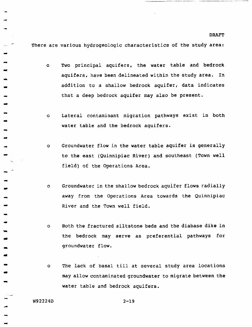
There are various hydrogeologic characteristics of the study area
o Two principal aquifers the water table and bedrock
aquifers have been delineated within the study area In
addition to a shallow bedrock aquifer data indicates
that a deep bedrock aquifer may also be present
o Lateral contaminant migration pathways exist in both
water table and the bedrock aquifers
o Groundwater flow in the water table aquifer is generally
to the east (Quinnipiac River) and southeast (Town well
field) of the Operations Area
o Groundwater in the shallow bedrock aquifer flows radially
away from the Operations Area towards the Quinnipiac
River and the Town well field
o Both the fractured siltstone beds and the diabase dike in
the bedrock may serve as preferential pathways for
groundwater flow
o The lack of basal till at several study area locations
may allow contaminated groundwater to migrate between the
water table and bedrock aquifers
W92224D 2-19
DRAFT
o Upward and downward vertical hydraulic groundwater
gradients between the bedrock and the water table aquifer
have been observed in several study area well clusters
o The observed changes in vertical hydraulic gradients at
different times of year are likely the result of seasonal
precipitation events and increases in groundwater
recharge Contaminated groundwater may therefore be
communicated between aquifers depending on the time of
year
o The On-site Interceptor System exerts an influence on the
local groundwater flow in the water table aquifer
233 Nature and Extent of Contamination
This section describes the nature and extent of soils contamination
within the Operations Area and groundwater contamination within
and in close proximity to the Operations Area This section
summarizes what is known to date from the RI investigations For
a more detailed analysis of the site contamination refer to the
Phase 2 Technical Memorandum Remedial InvestigationFeasibility
Study (HNUS June 1992)
W92224D 2-20
DRAFT
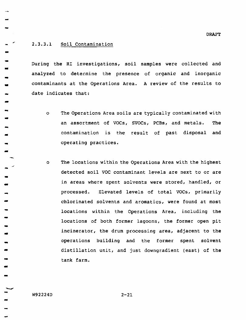
2331 Soil Contamination
During the RI investigations soil samples were collected and
analyzed to determine the presence of organic and inorganic
contaminants at the Operations Area A review of the results to
date indicates that
o The Operations Area soils are typically contaminated with
an assortment of VOCs SVOCs PCBs and metals The
contamination is the result of past disposal and
operating practices
o The locations within the Operations Area with the highest
detected soil VOC contaminant levels are next to or are
in areas where spent solvents were stored handled or
processed Elevated levels of total VOCs primarily
chlorinated solvents and aromatics were found at most
locations within the Operations Area including the
locations of both former lagoons the former open pit
incinerator the drum processing area adjacent to the
operations building and the former spent solvent
distillation unit and just downgradient (east) of the
tank farm
W92224D 2-21
DRAFT
o Soils with elevated SVOC concentrations were found
adjacent to the former lagoons the process area and the
open pit VOCs in the Operations Area soils were
generally accompanied by SVOCS
o Soils with elevated PCB concentrations were found
adjacent to the operations building the former lagoons
and the open pit
o Two areas with comparatively elevated inorganics
contamination were identified the former open pit and
adjacent to the process area
Table 2-1 presents the range of contaminants detected in soils
within the Operations Area subdivided into categories of
contaminants (VOCs SVOCs Pesticides and PCBs and Inorganics)
Figure 2-5 presents the approximate extent of total VOC
contamination in soils within the Operations Area More detailed
summary tables of the Operations Area soil sampling results by
boring location and a figure indicating those locations are
presented in Appendix A
W92224D 2-22
T A B L E 2 - 1 DRAFT RANGE OF DETECTED CONTAMINANTS
PHASE 2 SAMPLING 1991 OPERATIONS AREA
SRSNE INC SITE SOUTHINGTON CONNECTICUT
C T D H S STDS (utf l )
2
1000
7
1
200 5
5 5
I
10 5
1000
MCL
2
7
100 70
5
200 5
5 5
5
5
1000 700 100
10000
VOLATILE ORGANIC
COMPOUNDS
Methylene Chloride Vinyl Chloride Chloroethane Acetone 2 - Butanone Carbon Disulfide 11-Dichloroethene 11 - Dichloroethane
U-Dlchloroethenc (TOTAL) transmdash12-dichloroethene cis-l2-Dichlorocthene Chloroform 12-Dichlorocthane
111-Trichloroethane Carbon Tetrachloride Vinyl Acetate
12mdashDichloropropane Trichloroethene 112 -Trichloroethane Benzene 2-Hexanone 4-Methvl-2-penianone trans-l3-Dichloropropene Tetrachloroethene 1112-Tetrachlorocthane Toluene Ethylbenzene Styrene Xylene (total) Isopropyl benzene n-propylbenzene 135 -Trimethylbenzene 124-Trimethyl benzene
12 Dibromo 3-Chloropropane
SUBSURFACE SOILS | OVERBURDEN GW | BEDROCK GW | MIN MAX MIN MAX MIN MAX
ueke ueI ue1 uitl 8600J
360 J SJ 6201 SJF 8 J SF smiamsmshy100 + llOOJ 2 J 9500 J R R R R
22 38000 R R R R R R R R
430 J 1300 3 2 0 3 S F 15000 J S F bullimrsFii imaamF 325 790 J 290 J 5500 J 945 J 940J
9 79000 J 08 J
2 5 0 0 J F 110000 J F 275J F 5300J F 680J
940J SF bull - bull i 3 j s - -
275 J + 690000 78000 J SF 240000 J S F 17000 J SE 32000OJ SF 290J SF 9100 J SF 6 9 J J SE 2000J SJf
4J
220 J 07 J 146J + 800000 26000 J SF 300003 SF 14 J SF 41000J SK 910 J 2900 47 J
255 J + 650 J 610J SF ^bulliiimms-shyllOOJ 7900 J R R R R 410 J 130000J 22000 J 225 2100 J
3903 S 200 J 440000 2000 J SF 46 J 64003 SE
183 6 1700000 J 81000 J SF 1500003 S f 21 3800000 870 J F 60000J F 51J 7403 F
12000 2500000 49000J F 97 J 35 760000 4353
1200J 13 083
13
950 J 26 J 7103
R
Notes
(+) The sample was averaged wilh its duplicate = Value was rejected Medium level sample = Exceeds Connecticut DHS Standards bullbull Value is estimated = Exceeds Federal MCLs
W92224D 2-23
TABLE 2-1 (continued) RANGE OF DETECTED CONTAMINANTS PHASE 2 SAMPLING 1991 OPERATIONS AREA SRSNE INC SITE SOUTHINGTON CONNECTICUT Page 2
DRAFT
CTDHS MCLi SEMIVOLATILE SUBSURFACE SOILS | OVERBURDEN GW I BEDROCK GW I STDS (bulllaquofl) COMPOUND MIN MAX MIN MAX MIN MAX (bulllaquofl) bullgklaquo bullgkg bullgA bullgn bullgfl -grt
PHENOL 180 J 680J 22 4200 14 600 U - DICHLOROBENZENE 2J
75 75 14-DICHLOROBENZENE 10 600 12-DICHLOROBENZENE ISOJ 30
2-METHYLPHENOL 170 J 420 J 14 83 12 16 4-METHYLPHENOL 260J 280J 14 100 4J 13 ISOPHORONE 220J 700 J 8J 2J 9J BENZOIC ACID 870 J 24-DIMETHYLPHENOL 7J 11 2J 124-TRICHLOROBENZENE no J 530 J NAPHTHALENE 140 J 3300 J 3J 44 2J 3J 4-CHLORANIUNE 940 J 1900 J 4-CHLORO-3-METHYLPHENOL 2800J 16 2 - METH YLNAPHTHALENE 200J 2000J 3J DIMETHYL PHTHALATE 73 J 74 J 2J 17 3-NITROANILINE R R ACENAPHTHENE 170 J DIBENZOFURAN 110 J 24-DlNITROPHENOL 6J DIETHYL PHTHALATE 140 J 1600 J 2J 5 4-NITROANILlNE R R FLUORENE 69 J 160 J PHENANTHRENE 130 J 119$ J + IOJ ANTHRACENE 64J 190 J DI-N - BUTYLPHTHALATE S3 J S700J I J 52 J 3J FLUORANTHENE 61 J 470 J PYRENE 48J 270 J BUTYLBENZYLPHTHALATE 100 J 8600J 9J 63 J BENZO(a)ANTHRACENE 130 J CHRYSENE 89 J 220J BIS(2-ETHYLHEXYL)PHTHALATE 200J + 120000 J 11000
I DI shy N shy OCTYLPHTHALATE 580 J 1450 J + 26 J
CTDHS MCLi PESTICIDESPCB SUBSURFACE SOIL | OVERBURDEN GW | BEDROCK GW I STDS (bullgfl) COMPOUNDS MIN MAX MIN MAX MIN MAX
OKI) bullJtklt bullgkg bullRl bullg1 bullgl bullgl AROCLOR 1016 27 J 1200 J AROCLOR 1248 1550 +
1 05 AROCLOR 1254 380J 13000 J 13 SF
1 05 AROCLOR 1260 160 J 9700 J 85 SF
Notes
( + ) = The sample was averaged wilh its duplicate = Value was rejected = Medium level sample = Exceeds Connecticut DHS Standards = Value is estimated = Exceeds Federal MCLs
W92224D 2-24
DRAFT TABLE 2 -1 (continued) RANGE OF DETECTED CONTAMINANTS PHASE 2 SAMPLING 1991 OPERATIONS AREA SRSNE INC SITE SOUTHINGTON CONNECTICUT Page 3
C T D H S MCLi INORGANIC SUBSURFACE SOILS | OVERBURDEN GW | BEDROCK GW |
STDS (bullgl) COMPOUNDS MIN MAX FILTERED MIN MAX MIN MAX
(bullgl) bullg kg -gkg SAMPLE P - 4 B bullgl bullgl bullgl bullgl ALUMINUM 3150 10400 + 356 12200 51700 906 71300 ANTIMONY R
50 ARSENIC 050 J 54 20 J 50 210 40 J 80 J 1000 2000 BARIUM 341 J 1480 280 604 3510 J SF 106 ^269eJSFfshy
BERYLLIUM 032 J 085 11 J 54 J 19 J 85 J 5 5 CADMIUM 417 389 26 J 769 SF 425 J
CALCIUM 631 J 9410-1shy 65100 37100 349000 41850 J 140000 50 100 CHROMIUM 72 183 512 S U11SF bull 114J SF rfampSiF
COBALT 29 99 524 196 140 104 267 J J 1000 1300 COPPER 50 104 J 104 441 J 324 56 imi SF
IRON 3980 13700 7350 39100 84400 1930 99850 J 1$ 15 LEAD 53 J 1750 J 280 J SF 175 SF 53 bull -scim-sF^i
MAGNESIUM 1140J 5330 3360 9540 25700 1490 33400 5000 MANGANESE 752 J 440 J 6720 S 7610 S 37200 S 455 4000 J
2 2 MERCURY 035 J NICKEL 57 199 324 J 843 101 1022 J POTASSIUM 433 J 2250 5940 14000 J 12465 J 19600 J
10 50 SELENIUM 17 + 373 J 20000 SODIUM 699 4115-f 12600 10100 105000 J S 6320 16910 J
VANADIUM 101 J 309 381 J 114 328 152 ZINC 192 J 171 J 476 J 662 151 393 J 893
DIOXINSFURANS SUBSURFACE SOILS
COMPOUND MIN MAX
bullgkg bullgkg 2 37 8 - TCDD Equivalents 001 030
Notes
( + ) The sample was averaged with its duplicate = Value was rejected Medium level sample = Exceeds Connecticut DHS Standards Value is estimated = Exceeds Federal MCLs
W92224D 2-25
vo
Ngt rsgt
a reg
to
N
^laquo I ICHtV
reg SOIL SAUPIING LOCATIOM shy MUS PHASE 2 1 t9 l
SOIL SAMPLING LOCATION shy CPA TAT 1
B-9
1344400
bull bull bull
( T ) mdash -
mdash SAMPLE LOCATION IDENTIFIER
mdash TOTAL voca IN SOa ( U Q A B )
ESnwAlEO AREA Of SOIL CONTAMINAIKM
EIL POINT OR CHAUBOI
NOTE All LOCAHONS ARpound APPROXIMATE FOUR CPA TAT SAHPtC LOCAltONS (1SB8) ARC iNauoro IN AREAS MOT SAMPIEO BY NUS IN I M I
FIGURE 2-5 TOTAL VOCs IN SOIL OPERATIONS AREA 1991
SRSNE INC SITE SOUTHINGTON CONNECTICUT
60 120
3SCALE IN FEET ALL LOCATIONS ARE APPROXIMATE
O
i 1 I 1 I f l l l l l f l l l l l l l l i l l l f l l l i l l l i i
DRAFT
2332 Groundwater Contamination
The RI investigations to date have provided information on the
contaminant presence and distribution in the water table and
bedrock aquifers The observed contamination pattern is based on
the current non-pumping conditions of Wells Nos 4 and 6 Table
2-1 presents the range of contaminants detected in groundwater
within the Operations Area subdivided into categories of
contaminants (VOCs SVOCs Pesticides and PCBs and Inorganics)
The water table and bedrock aquifers are presented separately
Figure 2-6 presents the approximate extent of total VOC
contamination in the overburden aquifer Figure 2-7 presents the
approximate extent of total VOC contamination in the bedrock
aquifer More detailed summary tables of the Operations Area
groundwater sampling results are presented in Appendix B
Water Table Aquifer
For the overburden aquifer information to date indicates that
o VOC contaminants in groundwater are migrating away from
the Operations Area towards the Quinnipiac River and Town
well field The highest concentration of VOCs was
detected in Operations Area groundwater samples
V
W92224D 2-27
o ro ro
regro bull 1 ^ O
- mdashshyraquolaquo RWr Of WAY
IO I
IO 00
^ M W - 1 2 3 C asoJ
M W - 7 A ^JO
APPROXIMATE SCALE IN FEET
oFIGURE 2-6 TOTAL VOCs IN OVERBURDEN AQUIFER
SRSNE INC SITE SOUTHINGTON CONNECTICUT
P I- 1 f i l l f l I I I I i i I I I I f l l i I I i i 1 f 1
DRAFT
lt in
hshyD g1shy
az oin u UJ zD zo o
z^9 1 Q 5
IGU
RE
2
IN B
EDR
O
UTH
INi
U 0) O
sect - J
i O K
w Il l
W
d z^ UJ zwtr CO
W92224D 2-29
DRAFT
o At the Operations Area the highest levels of VOCs and
SVOCs in groundwater were detected primarily near the
former secondary lagoon and the tank farm The On-Site
Interceptor System) OIS may be limiting dispersion of
contaminants by inducing groundwater flow toward one
primary extraction well
o PCBs were detected in groundwater samples collected from
the P-IA and B well cluster in the Operations Area The
presence of numerous solvents and some surfactants may
have caused the PCBs to partition to the aqueous phase
o Groundwater contaminants observed at the Operations Area
and at downgradient locations have been identified by
SRSNE in NPDES reports and in the list of chemicals the
facility typically handled
o Contaminated groundwater with elevated concentrations of
VOCs and SVOCs appears to flow east from the Operations
Area to the Quinnipiac River along a limited path
o Groundwater contamination from the water table aquifer
appears to enter the shallow bedrock aquifer through the
till window present in the Operations Area The vertical
gradients observed support this conclusion
W92224D 2-30
DRAFT
o The presence of non-aqueous phase liquids may allow
transport of VOC contaminants in directions other than
that of groundwater flow
Bedrock Aquifer
For the bedrock aquifer information collected to date indicates
that
o VOC contaminants have been identified in all shallow
bedrock wells downgradient of the Operations Area
indicating that contaminant migration is pervasive in the
bedrock aquifer
o The shallow bedrock is more contaminated by VOCs than the
deep bedrock Vertical gradients indicate the potential
for contaminant penetration to deeper fractures from the
shallow bedrock The presence of VOCs in both the
shallow and deep bedrock supports this conclusion The
extent of contamination in the deep bedrock is unknown
because of the limited data available
o Contaminated groundwater at the Operations Area appears
to enter the shallow bedrock through a till window
adjacent to the tank farm and process area
W92224D 2-31
DRAFT
o Contaminated groundwater can migrate a substantial
distance downgradient in the fractured bedrock At some
well locations where the till is absent groundwater in
the shallow bedrock well is more contaminated by VOCs
than the corresponding overburden well
o Bedrock wells immediately upgradient (west) of the
Operations Area have low levels of VOC contamination
The presence of VOCs may have occurred because of some
other transport mechanism such as diffusion
W92224D 2-32
30
DRAFT
SCOPE OF THE RAPID REMEDIAL ACTION SUPPORT
An Engineering Evaluation and Cost Analysis will be prepared using
data developed from previous RI work and from preliminary risk
assessment and groundwater evaluations The EECA work assignment
will encompass a total of eight tasks Community relations (Task
0200) and administrative record (Task 1600) support are required as
part of the EECA process and are discussed in Section 40 of this
work plan The remaining EECA evaluation and report preparation
tasks include
o Task 0100 - Project Planning
o Task 0500 - Dewatering Evaluation
o Task 0600 - Contaminants Assessment
o Task 1000 - Rapid Remedial Alternatives Evaluation
o Task 1100 - EECA Report
o Task 1200 - Post EECA Support
The overall objective of the EECA is to develop and evaluate rapid
remedial action alternatives that will lead to the fulfillment of
the remedial action objectives described in Section 10 of this
Work Plan For purposes of this Work Plan a rapid remedial action
is equivalent to a removal action for which a planning period of at
least six months exists before on-site activities must be
W92224D 3-1
31
DRAFT
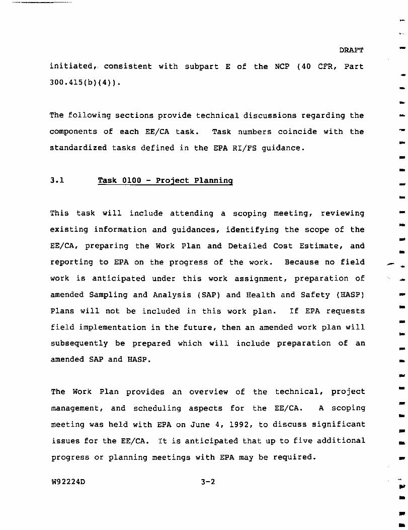
initiated consistent with subpart E of the NCP (40 CFR Part
300415(b)(4))
The following sections provide technical discussions regarding the
components of each EECA task Task numbers coincide with the
standardized tasks defined in the EPA RIFS guidance
Task 0100 - Project Planning
This task will include attending a scoping meeting reviewing
existing information and guidances identifying the scope of the
EECA preparing the Work Plan and Detailed Cost Estimate and
reporting to EPA on the progress of the work Because no field
work is anticipated under this work assignment preparation of
amended Sampling and Analysis (SAP) and Health and Safety (HASP)
Plans will not be included in this work plan If EPA requests
field implementation in the future then an amended work plan will
subsequently be prepared which will include preparation of an
amended SAP and HASP
The Work Plan provides an overview of the technical project
management and scheduling aspects for the EECA A scoping
meeting was held with EPA on June 4 1992 to discuss significant
issues for the EECA It is anticipated that up to five additional
progress or planning meetings with EPA may be required
W92224D 3-2
DRAFT
This task also includes preparation of monthly progress reports
which will include a narrative description of the status of each
task as well as a financial summary
311 Work Plan and Cost Estimate Preparation
This Work Plan presents a summary of information for the SRSNE site
including a site description potential sources of contamination
on-site objectives of the EECA the scope of the EECA the
project management approach and a project schedule The Work Plan
provides an overview of how the project will be managed and the
types of activities to be conducted The detailed Cost Estimate
will present the Level of Effort hours and costs (including Other
Direct Costs and subcontractor services) required to implement the
Work Plan It is anticipated that EPA will review and prepare
comments within two weeks of receipt of the draft Work Plan After
receipt of the comments HNUS will prepare a Final Work Plan and
Cost Estimate
Up to ten copies of the draft and final versions of the Work Plan
and three copies (draft and final) of the Cost Estimates will be
provided to EPA
W92224D 3-3
32
DRAFT
Task 0500 - Dewatering Evaluation
A groundwater flow model will be prepared using the USGS MODFLOW
computer model The model will be constructed using data gathered
during the Phase 2 site investigation and from previous
investigations
The model will consist of three layers The first layer will
represent the water table aquifer the second will represent the
glacial till unit and the third layer will represent the upper
fractured bedrock Hydraulic values measured during the prior RI
site investigations will be assigned to their respective layers
The majority of the data collected during the prior investigations
was collected to the east and downgradient of the Operations Area
Because of this the hydrogeologic conditions west of the
Operations Area must be approximated based upon the available data
The hydraulic values assigned to this area will be adjusted within
appropriate limits until the model recreates the measured August
1991 groundwater flow conditions within the Operations Area
A sensitivity analysis will be performed on these assumptions for
model input west of the Operations Area
W92224D 3-4
DRAFT
The model will then be used todetermine the pumping rate number
of wells and well spacing for a dewatering system The objective
of the dewatering system will be to maintain the groundwater
elevation at or below the top of the till or bedrock within the
Operations Area Capital and operating costs of the dewatering
system will be estimated
As part of the conceptual design of the dewatering system the
pumping rate will be determined for three groundwater scenarios
The first is the observed conditions of August 1991 The second is
the October 1991 condition The third condition is one that would
result in the breakout of groundwater at the toe of the slope along
the west boundary of the Operations Area This final scenario is
believed to represent the worst condition and therefore the highest
required pumping rate
The model will also be used to assess the viability of two
implementation options The first option is the use of an
upgradient interceptor trench west of the Operations Area This
trench may be useful in controlling the groundwater elevations
within the Operations Area by intercepting groundwater before it
enters the Operations Area This interception of clean water would
reduce the volume of groundwater requiring treatment The second
option is to dewater the Operations Area in stages (eg successive
W92224D 3-5
33
DRAFT
5 foot depthintervals) to allow a phased implementation of soils
treatment
Finally the model will be used to evaluate the effectiveness of
the existing On-site Interceptor System (OIS) This evaluation
will determine if the existing system can be utilized as a
component of the dewatering system It will also evaluate the
usefulness of continued operation of the OIS during Operations Area
dewatering
At the conclusion of the groundwater data evaluation an interim
report will be prepared The results of the computer analysis will
be presented including the three flow scenarios and the two
implementation options The interim report will describe the
conceptual design of the dewatering system and projected associated
costs It will also identify site access considerations for
installing structures for dewatering and monitoring A total of
three meetings with EPA are anticipated for this task
Task 0600 - Contaminant Assessment
A limited evaluation of soil and groundwater contaminants will be
required for the EECA process Contaminants of concern and
removed cleanup levels will be defined for both the dewatering and
soil treatment segments of the rapid remedial action These
W92224D 3-6
DRAFT
removalcleanup levels will consist of- media-specific goals for
protecting human health and the environment Removal cleanup
levels for soils will be developed based on a short-term
(preliminary) soils risk assessment which will consider
contaminants of concern (VOCs only) and exposure routes and
receptors
The contaminated occurrence and distribution will be reviewed and
chemicals of concern (COCs) selected for the development of removal
clan-up goals for the Operations Area soils The following factors
will be considered in the chemical of concern selection process
o Contaminant concentration in the soils
o Frequency of detection
o Chemical fate and transport (eg chemical volatility
vapor pressure Henrys Law Constant)
o Toxicity
The concentration-toxicity screen (CT-screen) presented in the EPA
Risk Assessment Guidance for Superfund Volume I Human Health
Evaluation Manual (Part A) will be used in the COC selection
process The objective of CT-screen is to identify chemicals in a
particular medium that based on concentrations and toxicity are
most likely to contribute significantly to risks calculated for
exposure scenarios involving that medium so that the risk
W92224D 3-7
DRAFT
assessment is focused on the most significant chemicals
The human exposure scenarios for the preliminary risk analysis will
include
Incidental ingestion of soils by onsite workers
Dermal contact with soils by onsite workers
Inhalation of Soil ParticulatesVapors by onsite
workers
Inhalation of Soil ParticulatesVapors by downwind
residents
Potentially acceptable removal cleanup levels ie levels which
will make the soil safe to excavate and handle during subsequent
remedial actions will be proposed based on the results of this
preliminary soils risk assessment
Removal cleanup levels for groundwater will be developed based on
chemical- and location-specific ARARs and other appropriate risk-
based levels For example effluent discharge limits and
requirements may include the Ambient Water Quality Criteria and the
current SRSNE NPDES permit limits EPA will consult with the CT
DEP and provide further direction to HNUS on developing the
groundwater removal cleanup levels
W92224D 3-8
34
DRAFT
At the conclusion of the contaminant assessment an interim report
will be prepared The results of the short-term (preliminary)
soils risk assessment will be presented The interim report will
also describe the ARARs evaluation for determining the groundwater
removal cleanup levels Included in the interim report will be two
tables one indicating the interim soil chemicals of concern and
the proposed soils removal cleanup levels and the other indicating
the interim groundwater chemicals of concern and proposed
groundwater removal cleanup levels These two tables will need to
be finalized before the rapid remedial action alternatives
evaluation can be concluded As many as four meetings with EPA may
be needed for this task
Task 1000 - Technical Evaluations of Alternatives
The EECA will use data collected during the prior RI field
investigations and the results of the contaminant assessment to
identify a short list of applicable remedial technologies
formulate rapid remedial action alternatives and evaluate these
alternatives for effectiveness implementability and cost The
alternatives will also be examined to determine whether they
contribute to the efficient performance of any anticipated long
term remedial action and comply with Applicable or Relevant and
Appropriate Requirements (ARARs) to the extent practicable
W92224D 3-9
DRAFT
The technical evaluation will be subdivided by media into the
following two subtasks
o Soil Remediation Evaluation
o GroundwaterVapor Remediation Evaluation
These tasks are described in more detail in the following sections
As many as four meetings with EPA may be required to complete this
task
341 Soil Remediation Evaluation
The selection of soil remediation technologies available for the
rapid remedial action is limited to in-situ treatment processes
The short list of in-situ technologies to be considered as given
in the SOW and discussed at the scoping meeting of June 4 1992
includes vapor extraction and thermal desorption in conjunction
with vapor extraction Soil flushing will also be considered if
the results of the evaluation indicate that dewatering the
Operations Area or implementing vapor extraction is impracticable
HNUS will incorporate the technology screening treatability results
developed by EPA ORD Cincinnati Ohio if available in a timely
manner Additional in-situ technologies may be identified by HNUS
and added to the EECA process at the request of the RPM
W92224D 3-10
DRAFT
A conceptual design will be described for each alternative in
sufficient detail to include the location of areas to be treated
approximate volumes of soil to be addressed and potential
locations for required treatment facilities and structures The
definition of each alternative may include preliminary design
calculations process flow diagrams sizing of key components
preliminary site layouts and potential sampling and analysis
requirements For the conceptual design of the vapor extraction
alternative HNUS will consider the description provided by EPA
RSKRL Ada Oklahoma
A detailed analysis of rapid remedial action alternatives will be
performed and will consist of
o A discussion of limitations assumptions and
uncertainties concerning each alternative
o Assessment and summary of each alternative against
evaluation criteria
o Comparative analysis among alternatives to assess the
performance of an alternative relative to each evaluation
criterion
W92224D 3-11
DRAFT
The three primary evaluation criteria developed for non-time
critical removal actions are effectiveness implementability and
cost Two additional criteria the ability of the alternative to
achieve ARARs and to contribute to the performance of the long term
remedial action will also be considered
The effectiveness evaluation will address the extent to which the
completed action can achieve the interim cleanup levels for VOCs in
soils based on making the soils safe to handle during
implementation of the long term remedial action The
implementability evaluation will consider the availability and the
technical and administrative feasibility of the alternative Total
costs of each alternative will be estimated
Applicable or Relevant and Appropriate Requirements (ARARs) will be
considered during the detailed evaluation of alternatives
Alternatives will be assessed on whether they attain ARARs or other
federal and state environmental and public health laws Compliance
with action- chemical- and location-specific ARARs will be
evaluated Each alternative will specify how ARARs are or are not
attained The actual determination of which ARARs are requirements
to be achieved to the extent practicable will be made by the EPA
W92224D 3-12
H ^
DRAFT
The soil treatment alternatives will also be qualitatively examined
to determine the extent to which they contribute to the efficient
performance of any anticipated long term remedial action
Consideration will be given to each alternatives ability to
shorten the duration improve the implementability or reduce the
risks of subsequent soil remedial actions
342 GroundwaterVapor Remediation Evaluation
A preliminary list of applicable technologies for groundwater
remediation at the SRSNE site will be identified based on
information gathered during previous investigations at the site
area The technology types to be used alone or in combination will
be evaluated for applicability to treating both the groundwater
extracted during dewatering and the vapors produced during
treatment of soil
The treatment technologies will then be assembled into a limited
number of rapid remedial action alternatives The temporary
UVoxidation treatment to be installed by CT DEP will be considered
as one of the alternatives A conceptual design will be described
for each alternative in sufficient detail to include the location
of groundwater to be treated or contained approximate volumes of
groundwater to be addressed and potential locations for
interceptor trenches or discharges to surface water The definition
W92224D 3-13
DRAFT
of each alternative may include preliminary design calculations
process flow diagrams sizing of key components preliminary site
layouts and potential sampling and analysis requirements All of
the water treatment alternatives will be appropriately sized to
handle the quantity of water predicted by the dewatering
evaluation
A detailed analysis of rapid remedial action alternatives will then
be performed and will consist of
o A discussion of limitations assumptions and
uncertainties concerning each alternative
o Assessment and summary of each alternative against
evaluation criteria
o Comparative analysis among alternatives to assess the
performance of an alternative relative to each evaluation
criterion
The three primary evaluation criteria developed for non-time
critical removal actions will be effectiveness implementability
and cost Two additional criteria the ability of the alternative
to achieve ARARs and to contribute to the performance of the long
term remedial action will also be considered
W92224D 3-14
DRAFT
The effectiveness evaluation will address the extent to which the
completed action can achieve the interim cleanup levels for the
contaminants of concern in groundwater based on making the
treatment effluent achieve ARARs for discharge to the river The
implementability evaluation will consider the availability and the
technical and administrative feasibility of the alternative Total
costs of each alternative will be estimated Treatment system
operating costs will be limited to the period up until either
interim cleanup levels in soil are achieved or the long terra
remedial action is initiated For planning purposes this is
assumed to be April 1996
In addition to the chemical-specific ARARs incorporated into
establishing the interim cleanup levels ARARs will also be
considered during the detailed evaluation of alternatives
Alternatives will be assessed on whether they attain ARARs or other
federal and state environmental and public health laws Compliance
with action- and location-specific ARARs will be evaluated Each
alternative will specify how ARARs are or are not attained The
actual determination of which ARARs are requirements to be achieved
to the extent practicable will be made by the EPA
The groundwater treatment alternatives will also be qualitatively
examined to determine the extent to which they contribute to the
efficient performance of any anticipated long term remedial action
W92224D 3-15
DRAFT
Consideration will be given to each alternatives ability to serve
as or be incorporated into subsequent remedial actions
35 Task 1100 - Engineering EvaluationCost Analysis Report
A report will be prepared presenting the results of the Engineering
Evaluation and Cost Analysis The EECA Report will discuss the
removal objectives and alternatives considered Each alternative
will be described along with a detailed analysis of how each
addresses the evaluation criteria identified previously
The report will provide a comparative evaluation of all
alternatives in a summary table which highlights findings from the
detailed analysis The purpose of the comparative analysis is to
identify the advantages and disadvantages of each alternative and
to identify key tradeoffs to be evaluated by EPA The format for
the EECA Report is presented in Table 3-1 As many as four
meetings with EPA may be required to complete this task
36 Task 1200 - Post-EECA Support
After the completion of the EECA and publication of the EECA
Report HNUS will assist EPA in preparing design specifications and
drawings for the selected rapid remedial (removal) action During
W92224D 3-16
DRAFT
TABLE 3-1
EECA REPORT OUTLINE
I EXECUTIVE SUMMARY
II SITE CHARACTERIZATION A Site Description B Site Background C Analytical Data D Conditions for the Removal Action
III REMOVAL ACTION OBJECTIVES A Mass Removal of Contaminants B Control of Off-site Migration C Statutory Considerations D Scope and Schedule
IV IDENTIFICATION OF REMOVAL ACTION ALTERNATIVES A Soils Treatment Alternatives B Groundwater Treatment Alternatives
V ANALYSIS OF ALTERNATIVES A Effectiveness B Implementability C Cost D Attainment of ARARs E Contribution to Long Term Action
VI COMPARATIVE ANALYSIS
VII PROPOSED REMOVAL ACTION
W92224D 3-17
DRAFT
this Work Assignment HNUS will prepare and submit a draft final
(90) and final design (100) reports
361 Draft Final Design Report (90)
The Draft Final Design will provide a description of the soil
treatment and groundwater extraction systems groundwater and
vapor treatment systems and discharge conveyance systems The
Draft Final Design will encompass approximately 90 of the total
design effort and a submittal (10 copies) will be forwarded to
the EPA Work Assignment Manager for review and approval
The documents that will be prepared and included in this design
report will include the following
o Introduction
o Basis of Design
Identification of design issues and
uncertainties
A presentation of appropriate waste stream
analytical data including drawings depicting
existing site conditions (physical and
chemical)
W92224D 3-18
DRAFT
Assessment of applicable FederalState
regulations
Technology selection
o Draft final design site construction plans (including
well and equipment and utility citing) flow diagrams
and Process and Instrumentation Diagrams (PID)
o Design analysis including calculations (hydrogeologic
process and civil)
o Technical performance specifications
o Technical construction specifications
o Construction schedule including a suggested sequencing
o Site and remedial system monitoring requirements
o Plant OampM requirements
o A site specific Health and Safety Plan to be
implemented during construction
^ ^ m i t f 0 f
W92224D 3-19
DRAFT
o An assessmentstatement of applicable Federal and State
regulations and permits required to perform the work
o A Bid Form specific to the work to be performed
o Estimated construction cost (+20 to -15)
o Project Delivery Strategy
o Plant Operation and Monitoring Plan (Pilot Study) to
assess variable system operating conditions
As many as four meetings will be held with EPA prior to submittal
to discuss the intended design and scope of the construction
project The intent of these meetings is to minimize potential
revisions required by comments received after the initial
submittal and to expedite submittal of the 100 design report
As many as two meetings will be held with EPA after the submittal
of the 90 design report to discuss EPA comments
W92224D 3-20
DRAFT
362 Final Design (100)
The Final Design Report will revise and complete all deliverables
and will address 100 of the remedial design It is assumed that
the 100 submittal (10 copies) will be provided to EPA within 30
calendar days from receipt of EPA 90 design comments
Deliverables for the 100 design will include
o Final design plans and specifications in reproducible
format (ie mylar or velum drawings hard copy
documents and magnetic media)
o Final technical bid documents
o Final construction schedule
o Final cost estimates
o Identification of additional design
issuesuncertainties including potential long-lead
procurement items
o Final Health and Safety Plan for the remedial action
W92224D 3-21
DRAFT
o Final Plant Operation and Monitoring Plan (Pilot Study)
to assess variable system operating conditions
One meeting will be held with EPA after submittal of the 100
design report
363 Rapid Remedial Action Implementation
This Work Plan does not address activities by HNUS which may be
required for implementation of the removal action
Implementation activities may include
o solicitation and procurement of subcontractor(s)
o subcontractor oversight
o construction quality control
o monitoring
o operation and maintenance
Further description of these implementation tasks and their
respective costs will be provided through amendment to the EPA
Statement of Work and subsequent Work Plan Amendments
W92224D 3-22
DRAFT
40 COMMUNITY RELATIONS AND ADMINISTRATIVE RECORD SUPPORT
Section 415 of the NCP provides for an environmental review and
public participation component to removal actions for which a
planning period of at least six months exists These components
include an establishment of an EECA administrative record and a
public comment period to be held prior to a decision on initiation
of the removal action as well as a response to the public
comments HNUS will assist EPA in these components of the EECA
process A more detailed description of the community relations
and administrative record tasks follows
41 Task 0200 - Community Relations
As specified in the EPA Statement of Work HNUS will provide
additional Community Relations Support during the rapid remedial
(non-time-critical removal) actions These activities are
described as follows
411 Task 0210 - Update the Community Relations Plan
At the direction of EPA HNUS will assist in revising the existing
Community Relations Plan (CRP) to address changes in community
concerns and particular concerns anticipated during the EECA
W92224D 4-1
DRAFT
HNUS may conduct on-site interviews with the interested and
affected residents to ascertain changes in community concerns The
revised CRP may also evaluate which community relations techniques
have been effective and should be continued and recommend
activities to address the rapid remedial action HNUS will provide
draft and draft final copies of the revised CRP to the EPA RPM and
the EPA Superfund Community Relations Coordinator (CRC) Six
copies of the final document will be provided to EPA
One revision of the CRP two meetings with EPA and one trip to the
site area are anticipated for this task
412 Task 0220 - Provide Public Meeting Support
HNUS will provide support for the public informational meeting on
the draft EECA Public meeting support will include attending a
planning meeting with EPA coordinating meeting logistics
preparing audio-visual material attending a dry-run preparing
a list of tough questions attending the informational meeting and
preparing a draft and final meeting summary
A total of two meetings with EPA and one trip to the site area are
anticipated for this task
W92224D 4-2
DRAFT
413 Task 0230 - Prepare a Fact Sheet
HNUS will provide a draft draft final and final version of up to
four fact sheets The first will summarize the EECA The second
third and fourth fact sheets will discuss the progress of the
EECA The documents will be written in accordance with the EPA
Region I format As needed graphics in support of the fact sheet
may be developed HNUS will provide EPA with up to 2000 copies of
the fact sheet for distribution to the site mailing list
A total of four meetings with EPA are anticipated for this task
414 Task 0250 - Provide Public Hearing Support
HNUS will obtain a location for and arrange for stenographic
support at the public hearing HNUS will coordinate the inclusion
of EPAs corrections to the draft to ensure the final transcript is
an accurate reflection of the hearing proceedings
One meeting with EPA is anticipated for this task
415 Task 0260 - Publish Public Notices
HNUS will prepare and coordinate publication of two public notices
to appear in up to six local newspapers The first notice will
W92224D 4-3
DRAFT
announce the availability of the draft EECA for public review and
comment The notice will identify the date time and location of
both the public meeting and the public hearing and will announce
the public comment period A press release with this information
will also be prepared at EPAs request The second notice will
announce the selection of the EECA and its schedule HNUS will
prepare a draft and final version of the notices and the press
release Two tear sheets of each copy of the notices will be
submitted to EPA for inclusion in the Administrative Record and
Information Repository
Two meetings with EPA are anticipated for this task
416 Task 0270 - Maintain Information Repositories
HNUS will assist EPA in assuring that the public information
repository is fully stocked with EECA-related documents
One meeting with EPA and two trips to the information repository
are anticipated for this task
417 Task 0290 - Prepare a Responsiveness Summary
HNUS will assist EPA in preparing a Responsiveness Summary that
accurately characterizes written and oral comments on the draft
W92224D 4-4
DRAFT
EECA and responds clearly to each characterization HNUS will
prepare three draft versions and a final Responsiveness Summary
Three meetings with EPA are anticipated for this task
42 Task 1600 - Administrative Record
HNUS will prepare and compile the EECA Administrative Record The
Administrative Record is a subset of the site file containing
documents that relate to public involvement and the selection of
the rapid remedial action The Administrative Record supports the
Action Memorandum which is tentatively scheduled for December
1992 HNUS will coordinate all Administrative Record activities
with the Task Manager Brenda Haslett the Work Assignment Manager
for Task 1600 EPA will provide HNUS with an index of the site
file when that index is available
HNUS will contact the Task Manager as required to discuss progress
HNUS will also ensure that EPA retains the diskette(s) containing
the indexes of the EECA Administrative Record and other relevant
materials HNUS anticipates subcontracting much of the
administrative records support work HNUS or its subcontractor will
perform the following Administrative Record subtasks
W92224D 4-5
DRAFT
Compile Administrative Record
Subtask 1 - Meet with the RPM the Site attorney and the Task
Manager to discuss Administrative Record procedures and the
schedule HNUS will prepare a schedule subsequent to the meeting
The EECA Administrative Record will be delivered to the
information repositories at the same time the final EECA Report is
made public
Subtask 2 - Assist the site team in compiling documents comprising
the EECA Administrative Record File (Refer to Selecting
Documents for Region I Superfund Site Administrative Records
Version 20 dated September 14 1988)
Subtask 3 - Prepare a draft index for the EECA Administrative
Record (Refer to Citation Formats for Region I Superfund NPL and
Superfund Removal File Administrative Record Indexes Version 30
dated October 18 1988) The site team will have ten working days
to review the draft index and to provide comments and changes to
HNUS After concurrence by the site team on the Administrative
Record File contents and draft index the final index will be
prepared
W92224D 4-6
DRAFT
Subtask 4 - Coordinate the duplication of the EECA Administrative
Record documents by consulting with Work Assignment Manager or
Records Center Manager on whether to use GSA printing services or
in-house copying resources
Subtask 5 - Assemble two copies of the EECA Administrative Record
and Index into binders (Refer to Binder Specifications for NPL
site Administrative Records and Indexes in Region I Version 10
dated March 16 1988) HNUS will supply the binders divider pages
and labels Both bound copies of the Administrative Record will be
returned to the Records Center
W92224D 4-7
DRAFT
50 PROJECT DELIVERABLES AND SCHEDULE
This section describes the major and interim deliverables
anticipated during the course of the EECA process The schedule
for these deliverables is also provided
51 Major Deliverables
The following major deliverables are projected during
implementation of this work assignment Each of these documents
will be submitted in draft for EPA comment and in final form
unless otherwise noted
EECA Work Plan
Draft EECA Report
Draft Final EECA Report (published for public comment)
Final EECA Report amp Responsiveness Summary
Draft Final Design Report
Final Design
Revised Community Relations Plan
Community Relations Fact Sheet(s)
W92224D 5-1
DRAFT
52 Interim Deliverables
The following interim deliverables are projected during the
implementation of this work assignment Each of these documents
will be submitted in a technical memorandum format EPA approval
of the interim deliverables will be required before subsequent work
on the pertinent sections of the EECA analysis can proceed
Dewatering Evaluation Interim Report
Contaminant Assessment Interim Report
53 Project Schedule
The Project Schedule (Figure 5-1) shows the tasks and activities
for the SRSNE EECA The schedule begins upon concurrence with and
approval of the Work Plan by EPA At that time the schedule will
be revised so that actual dates replace the proposed dates The
schedule allows four weeks for EPA to review each submittal The
schedule also allows three weeks from receipt of EPA comments for
resubmittal of final or draft final documents
W92224D 5-2
f i i i i i i i i i i i l i i i i i I I I I i l i i i l I I I I I i
I M mr Hftvi JUM I JUL I Mt r ^ gp I ncr i MAV I m I M I m i m i m i WM I M I JUL I M ^ I ggp i DCT I NOV I DEC
T )1Q0 PROJECT PLftNNING
bullDELIVER DRAFT WORK PLAN
p2Q0 COMMUNITY RELflTIDNS SUPPORT
bullDELIVER REVISED CRP
bull DELIVER FIRST Ff CT SHEET
bullDELIVER RESPONSIVENESS SUMMARr
g yC^ DEWftTERING EVALUATION
bullDELIVER DEWATERING INTERIM REPORT
m o CON [AM IN ANT ASSESSMENT
bullDELIVER CONTAMINANT ASSESSMENT INTERIM REPORT
1QQQ AITERNATIVF^ EVALUATION
I UOO PREPARE EECA REPORTl S)
bullDELIVER DRAFT EECA REPORT
bullDELIVER DRAFT FINAL EECA REPORT
bullDELIVER FINAL EECA REPORT
1200 POST EECA SUPPORT
bullDELIVER DRAFT DESIGN REPORT
bull DELIVER FINAL DESIGN
1600 ADMINISTRATIVE RECORD SUPPORT
bullDELIVER EECA ADMINISTRATIVE RECORD O
Sheet 1 of 1I I laquoLtiraquoitraquo Blaquo- Ei r l raquolt tn SRSNE INC W A NO 3 0 - 1 R 0 8 bull ^
C S S S S S S Cri t ical A c t i f i t X ittstia ^ m H Z D Progmc Bar EECA TECHNICAL ASSISTANCE
FIGURE 5-1 Project Star IWYC Data Date2BJUNltl2
Priiiavera SyEtens [nc i w - i ^ v Project Finisn lOCTW Plot Pate asjuHqa
iiuH
DRAFT
60 PROJECT MANAGEMENT
The overall project management and control of the EECA for the
SRSNE site is discussed below
61 Project Organization
Mr George Gardner the Program Manager is responsible for the
overall management and implementation of the HNUS ARCS I contract
performed in US EPA Region I Mr Liyang Chu will serve as the
project manager for Work Assignment 30-1R08 and has the primary
responsibility for the execution of the Work Assignment including
technical quality oversightreview control of costs and schedule
coordination with other work assignments and implementation of
appropriate quality assurance procedures during all phases Ms
Marilyn Wade is the task manager for this Work Assignment and is
responsible for the implementation of activities described in this
Work Plan In general the technical disciplines and technical
staffing will be drawn from the HNUS Wilmington Massachusetts
office When specialized or additional support is required
personnel from other HNUS offices or the team subcontractor Badger
Engineers Inc may be used Figure 6-1 presents the project
organization the lines of authority and coordination
W92224D 6-1
DRAFT
62 Quality Assurance and Data Management
All work will be performed in accordance with the HNUS ARCS I QA
Program Plan which was submitted previously under separate cover
63 Cost Estimate
The overall cost for the performance of the EECA as described in
this Work Plan is presented in a separate document the Detailed
Costing Estimate
W92224D 6-2 ^ l
FIGURE 6-1 PROJECT ORGANIZATION DRAFT
DRAFT WORK PLAN EECA
SOLVENTS RECOVERY SERVICE OF NEW ENGLAND INC SITE
QUALITY ASSURANCE OFFICER
L GUZMAN
HEALTH amp SAFETY OFFICER
J PILLION
SOIL REMEDIAL ALTERNATIVES EVALUATION
NUS ARCS I PROGRAM MANAGER
GEORGE DGARDNER
DEPUTY PROGRAM MANAGER
A OSTROFSKY
PROJECT MANAGER
LCHU
__J
TASK MANAGER
MWADE
RISK ASSESSMENT
L SINAGOGA
CONTAMINANTS OF CONCERN
EXPOSURE RATES amp RECEPTORS
DEWATERING ANALYSIS
M HEALEY
PRELIMINARY DESIGN
ON-SITE INTERCEPTOR
CONTRIBUTION
EPA RPO
D KELLEY
EPA RPM
B SHAW M NALIPINSKI
GROUNDWATER amp VAPOR TREATMENT
EVALUATION
NOTE Line of communication direction and authority Line of communication and coordination
W92224D 6 -3
70
DRAFT
EQUIPMENT AND SUPPLIES
Because no field investigation activities are anticipated during
the performance of the EECA the only identified equipment
requirement is the use of vehicles for transportation to meetings
and site visits
W92224D 7-1
s X gt
APPENDIX A
OPERATIONS AREA SOIL SAMPLING RESULTS
I I I I i i l i l I I I I I I i l t I I i l i l i l i l i l I I I
1 COMPOUNDS Locaboo Depth
CHLOROETHANE METHYLENECHLORIDE ACETONE 11 -DICHLOROETHENE IJ -DICHLOROETHANE 1 5 - D I C H L O R O E T H E N E fTOTAL)
1 CHLOROFORM 2 - B U T A N O N E 111-TRICHLOROETHAN E VINYL ACETATE 1 2 - D I C H L O R O P R O P A N E TRICHLOROETHENE I U - T R I C H L O R O E T H A N E BENZENE 4 - M E T H Y L - 2 - P E N T A N O N E
12-HEXANONE TETRACHLOROETHENE
1TOLUENE CHLOROBENZENE ETHYL BENZENE STYRENE TfTTAL XYLENES TOTAL VOLATn -E ORGANICS (TVOCs)
TABLE4-3 PHASE 2 SUBSURFACE SOILS
TCL VOCS ANALYSIS - (APRIL - JULY 1991)
SRSNE INC SITE SOUTHINGTONCONNECTICin
UNHS (uglg)
1 OPERATIONS AREA
B-1
(9--in 1 B-2
( 9 - i r ) 1 B-4f+l
n5 -16 ) 1 B-5
(V-S) 1 B-7
rr-9) 1 B-S
( r - 3 1 1 B-14
fr-9) 11 B-IS (4--6)
8600J
1
1300 290J 1900
38000 170000 bull
980J 790J 7500J 680J 2400 J
110000
1
7500 J
63000
3000J
20000 J 13000J
470 J
920
420 J
240 J
llOJ
1500J
S60000J 2900 120 J
7000 J I400J
440000 220000
220 J 710000
910J 6S0J 7400 J 7900J
430000 500000
800000
9900J 61000
^10000
130000J
200000 490000
380J
2300 46000 1500
190J
200 J ISOOOJ
59000 40000
240000 1781910 J
230000
7600W 2778030 J 0
280000 73000 50000
13444001
76000 80000
310000 16320001
1200
2800 540701
2100
690 J 4950 J
23000J
150000J 193000 J
( + ) = The umple value was avenged wilh its duplicate
= Medium level sanple
J - Value is Estimated
B-16
n r - i3 i
430 J 140J 3500
1300J 36000
2300
410J llOOJ 6400
47000
100000 12000 18000
228211 i
1 P-IA ( i r - m
R
79000J
690000
170000 J
140000 1700000J
3800000 2500000 330000
94090001
P-2A(+)
I9-in 110
325 3731
37 JJ 2731
1461
25 J 1
2761 300
13301
5651 2laquo871
1 P-4A llaquo-io-)
95001
35000
11000
29000 98000
14000
33000
2293001
1 P-8 ri4-i6i
0
1 1 P-16
fl4-16l
9
22
41
6
21
35 971
TAELE 4 - 4 PHASE 2 SUBSURFACE SOILS
TCL SVOCS ANALYSIS - (APRIL - JULY 1991) SRSNE INC STTE SOUTHINOTONCONNECTICUT
UNITS (u(k()
OPERATIONS AREA 1
COMPOUNDS LocalioD B-I B-2 B-4 (+ ) B-S B-7 B-laquo B-14 B-I5 B-16 P - I A P-2A(+) P-4A P - laquo P-16
PHENOL
DcDlk ( l - U ) 680J
( r- i i i (10-201 (I -n 210J
(r-9i 540J
cr-in (I -in (O-e-) ( I f -m (W-2Q) ( i - i n (Q-Wi iv-vr ( T - U i ttOJ
P - D I C H L O R O B E N Z E N E 150J 2 - M E 1 H Y L P H E N O L 4201 I70J 4-METOYLPHENOL 260 2tOJ 270J ISOPHORONE 700 J 2 I 0 J 270 J 220 270J BENZOIC A a O 170 I24-TRIHLOROBENZENE NAPHTHALENE
noj 3300J
2401 1800
S30J 3200J IIOOJ 340J I40J 390 J 150 220J
4 - C H L O R A N I L I N E 940 J 1900J 4 - C H L O R O - 3 - M E T H Y L P H E N O L 28001 2 - M E r a Y L N A P H T H A L E N E 1400J JOOJ 2000 J 360J 220J 455 J 200J DIMETHYLPHTHALATE 73J 74 J A C E N A P K n i Y L E N E 3 - N m i O A N I L I N E R R R R R R R R A C E N A P H n i E N E I70J DIBENZOFURAN 1101 DIETHYL PHTHALATE 930 J 350J 1600J I40J l -N tTROANILINE R R R R R R R R FLUORENE I50J 160J 69 J PHENANTORENE 500J 320J 820J I30J ltS0J 1195J ANTHRACENE 64J 190 p i - N - B U T Y L P H T H A L A T E 4S00J 4400 S700J 2300J 4750 53 J FLUORANTHENE 4701 61J fYRENE 270 J 48J l l O J B imrLBENZYLPKTHALATE (600J 3000 2200 770J 4200J IIOOJ 3900J 150J 1500 lOOJ BENZO(a)ANTHRACENE 130J CHRYSENE 89 J 220 J BIS(2-EniYLHEXYL)PI fTHALATE 56000J 24000 200 J 42000 bull I2000J I3000J 11000J 120000J 4600 35500 700 D I - N - O C T Y L P H T H A L A T E I450J 5laquo0J BENZOfUFLUORANTHENE BENZO(k)FLUARANTHEN E BENZOfi lPYRENE I N D E N O l U J - c i U P Y R E N E
lKt36i Ut^i 200J 64S94J 1 ^ 9 raquo J 2115^1 12100J 123900) 4S90J 0 52240J 2233J 6 1370J O R O A N C S (SVOCs)
( f ) a Sample value avenged witkilsdupiiciie gt Medium level sample J shy Value is Estimated
I i I I I I I I i I i I I I I i I I I I I I I i I I i I II 1
l l l i l l l l l l l l l f l i l l i l I I I I 1 1 I i I If
TABLE 4-5 PHASE 2 SUBSURFACE S O t S
TCL PESTICIDESPCB ANALYSES (APRIL - JULY 1991) SRSNE INC SITE SOUTHINGTON CONNECTICUT
UNITS (ugkg)
OPERATIONS AREA
COMPOUNDS Location B - l B-2 B - 4 ( + ) B - 5 B-7 B - 8 B-14 B-15 Dcnth d - l l ) ( f - l l - ) (l0-20) ( I - T ) ( l -9 ) ( I - i r ) (I-in (0-6)
AROCLOR 1016 410J 550 J 360 J 240 J 220 J 65 J 1200 J AROCLOR 1248 ARO(XOR 1254 2500 J 13000 J 8400J 4900 J 2000 J 2100 J llOOOJ AROCLOR 1260 2100 J 9700 J 7100 J 2700 J 2200 J 1700 J 5000 J
TOTAL 5010 J 23250 J 0 15860 J 7840 J 4420 J 3865 J 17200 J
OPERATIONS AREA
COMPOUNDS Location B-16 P - I A P - 2 A ( + ) P-4A P - 8 P-16 Depth ( I l - I T ) (10-20) ( bull - bull ) (0-10) (10-20) (2-12)
AROCLOR 1016 27 J AROCLOR 1248 1550 AROCLOR 1254 380J 2000 J 1850 AROCLOR 1260 160 J 1900 J 3550
TOTAL 567 J 3900 J 6950 J 0 0 0
( + ) = The sample value was averaged with its duplicate J = Value is estimated
TABLE4-6 PHASE 2 SUBSURFACE SOILS
TAL INORGANICS ANALYSES (APRIL shy JULY 1991) SRSNE INC SFFE SOLTTHINGTON CONNECTICirr
UNITS (mgkg)
OPERATIONS AREA
COMPOUND Location B - l B-2 B-4r+) B-5 B-8 B-14 B-15 B-16 Depth r - i r I - i r W-2ff V-T r - i r I - i r V-6 i r - i T
ALUMINUM 7640 5890 6605 5920 9810 6480 9720 5260 ARSENIC 25 088 052 097 083 081 54 085 BARIUM 296 531 6055 505 705 434 J 1480 6Z1 BERYLLIUM 083 054 048 085 CADMIUM 183 417 389 CALCIUM 2440 1090 9410 2150 1090 J 813 J 2010 7520 CHROMIUM 183 148 1135 193 134 291 790 80 COBALT 92 55 99 amp3 COPPER 474 J 159 J 601 J 115 J 104 J IRON 12800 8240 10080 7680 13700 7970 11400 7920 LEAD 873 J 53 J 63 J 175 J 160 J 1750 J 63 J MAGNESIUM 4650 2360 3705 2560 5330 2490 3030 2900 MANGANESE 440J 186 J 2495 283J 214 J 142 J 338J 280J NICKEL 199 POTASSIUM 2250 1110 1765 1600 1350 995J loeoj ISIO SELENIUM 373 J 279 J SILVER SODIUM 271 4115 301 J THALLIUM VANADIUM 273 206 193 216 309 191 234 206 ZINC ISSJ 192 J 1 2235 205 J 48 i J 237 J m i 221 J
(+ ) = Sample value averaged with its duplicate J shy Value is estimated
P - L 10-20
3150 11
341 J
650 155
3980
1140J 752 J
433 J
101 J
P-2A(+^ i - i r 10400 Z7
4355 051 8a4 9945 3375 amp15 3075 11500 202 4010 338 149 1455 17
274 7345
P-4A V - W
6270 050 J 525
054 J
1190 84 52
8100
3280 214 J 78
1910
730
208 279
P -8 W-2V
5820 066 J 442
055 J
953 72 19
8010
2680 349 J 61
1640
699
188 208
P-16 2 - i r 9120 14
452 032 J
631 J 92 J 29 50
8980
1470 211 J 57 580 17 J
166 193 J
I I I i I I I I I i I I I i I I I I I i I i i i I r f II I
DRAFT
TABLE 4-7 PHASE 2 SOIL BORING SAMPLING SUMMARY
DIOXINSFURANS SRSNE INC SITE RIFS
SOUTHINGTON CONNECTICUT UNITS (ugkg)
DEPTH CONCENTRATION IN 2 3 7 8-TCDD LOCATION (FEET) EQUIVALENTS (ugkg)
8-1 1-3 001 J
B-5 1-3 000 J
B-5 3-5 000 UJ
B-5( + ) 3-5 0002 J
B-7 1-3 000 J
B-7 5- 000 J
B-8 1-3 000 UJ
B-14 1-3 0001 J
B-14( + ) r-3 000 R
B-14( + ) r-3 000 UJ
8-14 5-7 000 UJ
B-15 4-6 030
B-17 V 000 UJ
B-18 r 000 UJ
NOTES
(bulllaquo-) Indicates duplicate samples J Value is estimated UJ Non-detected value is estimated R Data rejected because recovery of internal standards were outside the
acceptable range
gt
O R 09
APPENDIX B
GROONDWATER SAMPLING RESULTS
I 1 i I I i I I i I 1 I 1 I I i I I i I i I I I I I i I i I I I I I
TABLE 4 - PHASE 2 OVERBURDEN OROUNDWATER
VOCS ANALYSIS (METHOD SZ42) AUGUST 11 SRSNE INC SITE SOUTHINGTON CONNECTICUT
UNITS (UfI)
CT DHS MCL C O M P O U N D UPGRADIENT J OPERATIONS AREA CIANCI PROPERTY STANDARDS N L A Z Y L A N
- (tW T W - 1 2 P - I B P - 2 B P - 4 B P - U P-3B P - P - l l B P - I 2 MW-123C T W - 7 A ( + T W - 8 A CbloromclliMic
Broroomctbwic 2 2 Vinyl Chlohde laquo2raquoJ SP J laquo 0 ] SF 270 ) SF
Cbtoroeibwie t lOlaquo3 M O l 2 3 2 M )
Acelooc R R R R R R R R R R R
1000 2 shy Butuionc R R R R R R R R R R R Carbon Diiul f idc R R R R R 22 ) R R R R R
7 7 11-Oicbloroctbcnc T400ir SF laquo raquo j SI 15040] $ f I t -Djcbtorocthanc 29003 5500) 20 3 70 3 113 210)
too irant -1 2 - dicbloractbcnc laquo J 70 cigt-12-Dicbloroltlbcnlaquo IIOOOOJ P 21003 F 44 3
Cblororom
1 5 12-Dicblorocibanc laquo 4 0 ] SF 3 ) S 114 ] 8 P 200 200 t 11-Tricbloncdiaae 7 M laquo d ] SF laquo P laquo 0 laquo J S F |
s ] Carbon Tctracbloridc raquo i laquo O i SF IMJ s 5 5 12- Dkfalonopropaoc
5 5 Trichloroethene 2 (000 ] SP 3 0 laquo M J S i 14) 013 112-Tricbloracttaane
1 5 Bentenc laquoI0 3 SF M ) SF M J sF ( 2 ) SF 2-Meianone R R R R R R R R 4 -Mc tbv l -2 -pcn tanone 22000 J 3(0 3 I f M )
10 tram -1 3 - Dicbloropfopene
s S Tctracbloraettacne 2000] SF
1112-Tetrachlonictbanc 1000 1000 Toluene t lOOO] SF
100 Cblorobenzenc 33 53 700 Eibylbenzcne t o v m F 9 ) P t i n t 24 3 M l F 4WJ r 100 Styrene 4Mltraquo] r
10000 Xylene (total) 1200 J 7 ( J 24 3 400 3
123-Tribromopropane n-propylbeozene 30 3
135- Trimetbylbcniene 37) ten shy Butylbeniene 133
124-Triaictbylbcniaic bull 950 3 127 3 340) bullee-Butylbenzene 73
laquo00 13-Dicblorobenzcnc 7J 7$ 14 shy Diclilorobenzenc
p- lwpropyl io luenc 53 6U0 12 - Dicblorobenzenc 23
n shy Butylbenzenc
1 - Tricblorobenzene
Napbtbalene 93
T O T A L gt
12 Dibromo 3-Cbloropropane
O L A T I L E ORGANICS r rVOCS) | bull R
451100 ] s
1 I2 IraquoJ 2tStOlaquoJ 1 1S20J 1504 31 1
R 013
R
2 3 bull 150 3 1 M 0 ( ]
( + ) - T b c M i n p c value w u bullveraged witti i u duplicwc J ~ Value i l eatlmated [ bullbullS W Bzcccda Conn ectlcM DHS Sii mdards bull bull bull bull bull bull bull bull bull Eicccda Fcda ral MCLa R shy Value l i Re)eetc4
TABLE 4-10 PHASE 20VERBURDEN OROUNDWATER
TCL SVOC ANALYSES AUOUCT 1991 SRSNE INC SFTE SOUTHINOTDK OONNECnCUT
UNITS (ugl)
CTDHS MCLS OOMfOUND UPORADIENTl OPERATIONS AREA CIANCI PROPERTY STANDARDS (ug1) NLAZYLNE
(gl) TW-12 P-IB P-2B P-4B P-16 P-3B P-9 P - l l B P - U MW-12JC PHENOL 4200 22 7J
600 13- DICHLOROBENZENE 75 75 14- DICHLOROBENZENE I J
600 U - DICHLOROBENZENE 30 2-METHYLPHENOL a 49 14 23 4-METHYLPHENOL 100 64 14 17 ISOPHORONE I J 2J I J 24- DIMETHYLPHENOL 10 7J 11 U4--miCHLOROBENZENE 4J NAPHTHALENE 3J 44 7J 21 4-CHLORO-3-METHYLPHENOL 16 2-METHYLNAPHTHALENE 3J 6J DIMETHYL PHTHALATE 17 2J 2^4-DINnROPHENOL 6J DIETHYL PHTHAIATC 5J 2J PHENANTHRENE IOJ DIshy N - BUTYLPHTHALATE 521 14 I J I J BUTYLBENZYLPimiALATC 631 9J BIS(2-ETHYLHEXYL)PHrHAljTC 11100 DI-N-OCTYLPHTHAIATE 26 J
TOTAL 0 154731 237J Z3$J 40J 57J 0 1 I J 0 1 13J
(+) = The umple value wai averaged witb ib ltlu|iicate J shy Valie b etiiiiiated
rW-7A(+) 32J
415 J 630J
37J 2J 3J5
2J
778J
TW-8A IM
32 140
27 7J 27
3J
416 J
i I I i i I I I I I I I I I I 1 1 I I I I I I I I I I I I
I i l i l 1 1 I I i i i l 1 4 I I I I i l I I I I I I I i I
TABLE 4-11 PHASE 2 OVERBURDEN OROUNDWATER
TCL PESnCIDESPCB ANALYSES AUGUST 1991 SRSNE INC SOUTHINOTON CONNECnCirT
UNrrS(ugl)
CTDHS MCXs COMPOUND UPGRADIENT OPERATIONS AREA STANDARDS (laquog1) N LAZY LANE
TW-12 P-IB P-2B P-4B P-16 ALDRIN 44 shy DDD
I 03 AROCLOR 1254 1 05 AROCLOR 1260 vvlaquoJfSp
TOTAL 0 lt5 0 0 0
CTDHS MCU COMPOUND CIANCI PROPERTY STANDARDS (gl)
P-3B P-9 P-llB P-12 MW123C TW-7A(+) TW-laquoA ALDRIN 44 shy DDD
1 OS AROCLOR 1254 1 OS ARO(XOR1260
TOTAL i 0 0 0 0 0 0 0
CTDHS MCL COMPOUND TOWN PROPERTY MICKEYS STANDARDS (igl) OARAGE
(gI) P-13 MW-127B MW-7 MW-126B ALDRIN 44 shy DDD
1 05 AROCLOR 1254 1 05 AROCLOR 1260
TOTAL 0 0 0 0
( + ) = Sample value averaged with its duplicate Exceeds Federal MCL J = Value is Estimated Exceeds CoBoecliciil DHS Sundards
TABLE 4-12 PHASE 20VERBURDEN0R0UNDWATER
TAL INORGANICS ANALYSES AUGUST 1991 SRSNE INC SITE SOUTHINGTON CONNECTICUT
UNITS (ugl)
1 UPGRADIENT OPERATION iAREA CTDHS MCLs COMPOUND N LAZY LANE
STANDARDS (gI) TW-12 TW-12 P - I B P-2B P-4B P-4B P-16
(ugI) FILTERED FILTERED ALUMINUM 1 74900 109 12200 15300 51700 J 356 24100 J ANTIMONY R
50 ARSENIC 30J 210 SO 70 ZOJ 100 1000 2000 BARIUM 714 J 689 3510 J SF tao s 694 280 604
BERYLLIUM 59 J 12 J M J 54 J 16 J 5 5 CADMIUM R 47 169 SP Z6J m39v
CALCIUM 21800 10700 349000 65600 80700 65100 37100 50 100 CHROMIUM 137 SF bull- t 9 J laquo S bullbullbullbull 52J0 S 111 S F -5 i 2 S bullbull
COBALT 945 J 445 J 413 140 524 196 1000 1300 COPPER 122 J 441 J 743 324 104 655
IRON 115000 113 84400 39100 67200 J 7350 47500 J 15 15 LEAD
MAGNESIUM W9J SF
41800 2690 bull-2ISiPs
20100 mxji tv
13600 280 J SF
25700 3360 53aJ^sF
9540 5000 MANGANESE 3380 J 33 J 37200 S 11300 S 82M S V -vm-sm 7610 S
2 2 MERCURY 035 J NICKEL 127 J 324 J 375 843 315 POTASSIUM 22200J 767 14000 J 5940 12900 6680
10 50 SELENIUM 20000 SODIUM 5570 J 6560 105000 J S 10100 10700 12600 2 ^ S
THALLIUM VANADIUM 227 J 381 J 114 498 ZINC 344 662 908 151 476 J 111
(-lt-) = The sample value was averaged wilh its duplicate Exceeds Fcdlaquolaquol MCL R = Value is Rejected J = Value is estimated Exceeds Coaneclicat DHS SUndard
i I I I I I I I I I i i i l I I I I I I I i I I I I i
I 1 I I I I I I I 1 1 I I I I I I 1 1 I I I I 1 1 I I I I I 1
CTDHS STANDARDS
(utA)
2
1000
7
1 200
5 5 5
1
10 5
1000
75
MCL
2
7
100 70
5 200 5 5
s
5
5
1000
too 700 100
10000
600 75
600
TOTAL VOLATUE ORGAN
Notes
COMPOUND
CUoroBelhaac BroaoDCthaiie Vii)l Chloride CUorocthaDe Acctose 2-Buunone
Crboa Disulfide M-DicUorMlheae lI-Dichloroethlaquoie tnBS-l2-iSchlongtclbraquoe cis -12 - DicUoroetheae Chloroform U-Dichlotoelhaae 111-Tnchloroclhaae Carboa Tetrachloride 12-Dichloropropaae Trichloroetheae lU-TiichlongteihsBc Beazeae 2-HeuBOBe 4-Me(hil-2-peaUBoBe tnas-13-DichlofopropeBe TetracUoroelheae 1112-TctrachlorocthaBe Tolieae CUorobeazcBc Elh]4 beazeae Styreae Xyleae (total) Isopropytbeazeae 123-Tii bromopropaae a-prop)l beazeae 135-Tiimelhylbeazeae tert-But)lbeBzeae 124-Tiimelh]4beazeae sec - Butylbeazeae 13-DichlorobeazeBe 14-DichlorobeazeBe p - Isoprop)4tolueae 12 - Dichlorobeazeae a-BHtgtl beazeae 124-Toe hlorobeazeae Naphlhaleae 2 Dibromo 3-ChloropropaBe CS (TVOCS)
TAa-E4-13 PHASE 2 BEDROCK OROUNDWATER
VOCS ANALYSIS (METHOD 524i) AUGUSTT 1991 SRSNE INC STTE SOUTHINGTON CONNE(mCUT
UNTTS (ugl)
UPGRADIENT OPERATIONS AREA W OPS AREA IjZYLANE DELAHUNTY
TW-10 MW-129 P-ii P- IA P-2A(+)
llOJ SF 8J SF 2J
R R R R R R R R R R R R R R R
1600] SF 190J SF 940 J 94JJ
OS J $300J F 2751 P
J 3 J S 17000 J SP 2000J SF 69SS SF
07 J 14 J SP
47 J 191 S
R R R 2100J 22S1 390 J S
46 J 18J
192J 740J P 51J
97 J 435 J
IJ
08 J I J
26 J
R R 192J 0 0 30180J 5953J
F-4A P-8A
R R R
2300J SE
R R R
320000 J
41000 J
R
6400 J
1500001
23001
$F
SJP
SF
SF
F
R
710J
5227101 0
(+) = The sample value was averaged with its dapiicale Exceeds FedenI MCU R = Value is Rejected J laquo Value is csHmaled EBCccdsCoaaecliciil DHSSlaadards
TABLE 4-14 PHASE 2 BEDROCK OROUNDWATER TCL SVOC ANALYSES AUGUST 1991
SRSNE INC SITESOUTHINOTON CONNECTICUT UNITS (ugl)
CTDHS MCLS COMPOUND UPGRADIENT OPERATIONS i REA STANDARDS (ugl) W OPS AREA LAZY LANE DELAHUNTY
(laquogl) TW-10 MW-129 P-15 P - I A P - 2 A ( + ) P-4A P-SA PHENOL bull
600 13-DICHLOROBENZENE 2J 75 75 14-DICHLOROBENZENE 10
600 12- DICHLOROBENZENE 2-METHYLPHENOL 12 15 16 4-METHYLPHENOL 13 SJ 4J ISOPHORONE 9J 2J 24-DIMETHYLPHENOL 2J 124-TRICHLOROBENZENE NAPHTHALENE 2J 25 J 3J 4 - C H L O R O - 3 - METH YLPHENOL 2-METHYLNAPHTHALENE DIMETHYL PHTHALATE 24-DINITROPHENOL DIETHYL PHTHALATE PHENANTHRENE DI shy N shy BUTYLPHTHALATE 3J BUTYLBENZYLPHTHALATE BIS(2-ETHYLHEXYL)PHTHALATE DI shy N -OCTYLPHTHALATE
TOTAL 0 0 0 65 J 255 J 27 J 0
(+) = The sample value was averaged with its duplicate J = Value is estimated
l l l l l l l l l l l l l i l f l l l l l l ) i I
I l l i l l l l l l l l l I 1 1 I I I I I i E i e i i t
CTDHS STANDARDS
(raquogl)
1 1
CT DHS STANDARDS
(ugI)
1 1
CTDHS STANDARDS
(ugl)
1 1
MCU
(ugl)
OS 05
MCU
(ugl)
05 05
MCU
(ugl)
OS OS
COMPOUND
ALDRIN 44 - DDD AROCLOR 1254 AROCLOR 1260
COMPOUND
ALDRIN 44- - DDD AROCLOR 1254 AROCLOR 1260
COMPOUND
ALDRIN 44 - DDD
A R ( X L 0 R 1254
AROCLOR 1260
TABLE 4-15 PHASE 2 BEDROCK GROUNDWATER
TCL PESTICIDESPCB ANALYSES AUGUST 1991 SRSNE INC SITE RIFSSOUTHINGTON CONNECTICUT
UNITS (ugI)
1 UPGRADIENT OPERATIONS AREA W OPS AREA LAZY LANE DELAHUNTY
TW-10 MW-129 P-15 P - I A P - 2 A ( + )
13 SF
TOTAL 0 0 0 13 0
CIANCI PROPERTY
P-3A P - l l A P - 1 2 A ( + ) P-14 MW-123A 0070 017
TOTAL 024 0 0 0 0
TOWN PROPERTY
MW-12IA MW-121C MW-124C MW-127C MW-128
TOTAL 0 0 0 0 0
P-4A
0
MW-125A
0
M W - 5 ( + )
0
P-SA
0
MW-125C
0
MICKEYS GARAGE
MW-126C
1 0 1
+ ) = Sample value averaged wilh its duplicate Eicceds Federal MCL J 3s Value is Estimated Eieeedi Coiacclkat DHS Staadards
CTDHS MCU COMPOUND STANDARDS (ugfl) W OPS AREA
(laquolaquo) TW-10
ALUMINUM 58400 J ANTIMONY
50 ARSENIC 80 1000 2000 BARIUM 1490 S
BERYLLIUM 73 J 5 5 CADMIUM
CALaUM 35000 SO 100 CHROMIUM 731 S
COBALT 404 1000 1300 COPPER 142
IRON 47400 J 15 15 LEAD 676 J SF
MAGNESIUM 21800 5000 MANGANESE 5400 S
2 2 MERCURY NICKEL 674 POTASSIUM 12200
10 50 SELENIUM 20000 SODIUM 6540
THALLIUM VANADIUM 123 ZINC 171
(+) = The sample value was averaged with its duplicate J = Value is estimated
TABLE 4-16 PHASE2 BEDROCK OROUNDWATER
TAL INORGANICS ANALYSES AUGUST 1991 SRSNE INC STTE SOUTHINGTON CONNECTICUT
UN n S (ugl)
UPGRADIENT LAZYLANE DELAHUNTY
MW-129 MW-129 P-15 P-15 FILTERED FILTERED
248 J 23500 649
SOI 880 845 722 244
301
86900 S3500 39300 295(10 342 139 621
3$7J 24600 239 208 SP
3600 3510 9410 1250 29 11 J 841 147
309 6500
9580 11100 17000 23900 S
5691 S46
Exceeds Federal MCU R e Value is Rejected Exceeds Coaaecticul DHSSuadard
OPERATIONS AREA
P- IA
71300 R
80 J 26901 SP
831 R
140000
m m bull 4431
14601 SP 89700
50J1 SF 33400 40001
1011 196001
128001
1521 893
P-4A
9530
401 780 191
44200
104 568
13300 137 5660 1830
6890
3281
P-SA
906
106
59200
56 1930 53
1490 453
6320
P-2A(+)
527501
7J 1840J S
5851 4151
41S501 I H I SiF
26731 11281 S 998501
41351 SF 2270DI 25601
10211 124651
169101
13641 3931
I I i 1 I I I I I I I I I I f i l l

W92224D
DRAFT WORK PLAN
TECHNICAL ASSISTANCE
SOLVENTS RECOVERY SERVICE OF NEW ENGLAND INC SITE SOUTHINGTON CONNECTICUT
HALLIBURTON NUS Environmental Corporation
EPA Work Assignment No 30-1R08 EPA Contract No 68-W8-0117
HNUS Project No 5926
June 1992
George 5jl Gardner PE Project Manager Program Manager
CONFLICT OF INTEREST CERTIFICATION
HALLIBURTON NUS Environmental Corporation certifies that to the
best of its knowledge and belief there are no relevant facts andor
circumstances that would give rise to an organizational or
individual conflict of interest in connection with this work
planwork assignment or if any facts andor circumstances would
give rise to such conflict they have been disclosed in accordance
with Contract Clause H2 ORGANIZATIONAL CONFLICTS OF INTEREST
andor Contract Clause H16 NOTIFICATION OF CONFLICT OF INTEREST
REGARDING PERSONNEL
DRAFT
TABLE OF CONTENTS DRAFT WORK PLAN
TECHNICAL ASSISTANCE SOLVENTS RECOVERY SERVICE OF NEW ENGLAND INC SITE
SOUTHINGTON CONNECTICUT
SECTION PAGE
10 INTRODUCTION 1-1
20 SITE DESCRIPTION AND BACKGROUND 2-1 21 Site Area Description 2-1 22 Site History and Contaminant Source 2-7
Identification 221 Former Features 2-8 222 Current Features 2-13
23 Site Characterization 2-16 231 Site Geology 2-17 232 Hydrogeologic Characterization 2-18 233 Nature and Extent of Contamination 2-20
30 SCOPE OF THE RAPID REMEDIAL ACTION SUPPORT 3-1 31 Task 0100 - Project Planning 3-2
311 Work Plan and Cost Estimate 3-3 Preparation
32 Task 0500 - Dewatering Evaluation 3-4 33 Task 0600 - Contaminant Assessment 3-6 34 Task 1000 - Technical Evaluations of 3-9
Alternatives 341 Soil Remediation Evaluation 3-10 342 GroundwaterVapor Remediation 3-13
Evaluation 35 Task 1100 - Engineering EvaluationCost 3-16
Analysis Report 36 Task 1200 - Post-EECA Support 3-16
361 Draft Final Design Report (90) 3-18 362 Final Design (100) 3-21 363 Rapid Remedial Action Implementation 3-22
W92224D
DRAFT
TABLE OP CONTENTS (Continued) DRAFT WORK PLAN
TECHNICAL ASSISTANCE SOLVENTS RECOVERY SERVICE OF NEW ENGLAND INC SITE
SOUTHINGTON CONNECTICUT
SECTION PAGE
40 COMMUNITY RELATIONS AND ADMINISTRATIVE RECORD 4-1 SUPPORT 41 Task 0200 - Community Relations 4-1
411 Task 0210 - Update the Community 4-1 Relations Plan
412 Task 0220 - Provide Public Meeting 4-2 Support
413 Task 0230 - Prepare a Fact Sheet 4-3 414 Task 0250 - Provide Public Hearing 4-3
Support 415 Task 0260 - Publish Public Notices 4-3 416 Task 0270 - Maintain Information 4-4
Repositories 417 Task 0290 - Prepare a Responsiveness 4-4
Summary 42 Task 1600 - Administrative Record 4-5
50 PROJECT DELIVERABLES AND SCHEDULE 5-1 51 Major Deliverables 5-1 52 Interim Deliverables 5-2 53 Project Schedule 5-2
60 PROJECT MANAGEMENT 6-1 61 Project Organization 6-1 62 Quality Assurance and Data Management 6-2 63 Cost Estimate 6-2
70 EQUIPMENT AND SUPPLIES 7-1
APPENDIX A - OPERATIONS AREA SOIL SAMPLING RESULTS APPENDIX B - GROUNDWATER SAMPLING RESULTS
W92224D 11
DRAFT
TABLE OF CONTENTS (Continued) DRAFT WORK PLAN
TECHNICAL ASSISTANCE SOLVENTS RECOVERY SERVICE OF NEW ENGLAND INC SITE
SOUTHINGTON CONNECTICUT
TABLES
NUMBER PAGE
2-1 RANGE OF DETECTED CONTAMINANTS 2-23 3-1 EECA REPORT OUTLINE 3-17
FIGURES
N U M B E R PAGE
2-- 1 (GENERAL SITE LOCATION 2-2 2--2 1STUDY AREA 2-3 2--3 FORMER OPERATIONS AREA FEATURES 2-9 2--4 ICURRENT OPERATIONS AREA FEATURES 2-14 2-- 5 1OPERATIONS AREA VOCs IN SOIL 2-26 2--6 VOCs IN OVERBURDEN AQUIFER 2-28 2--7 VOCs IN BEDROCK AQUIFER 2-29 5--1 PROJECT SCHEDULE 5-3 6--1 PROJECT ORGANIZATION 6-3
W92224D iii
1
10
DRAFT
INTRODUCTION
At the request of the US Environmental Protection Agency (EPA)
Region I HALLIBURTON NUS Environmental Corporation (HNUS) will
provide technical assistance for a rapid remedial action at the
Solvents Recovery Service of New England Inc (SRSNE) site in
Southington Connecticut This technical assistance involves the
performance of an Engineering EvaluationCost Analysis (EECA) to
evaluate rapid remedial action alternatives and preparation of an
EECA Report The technical assistance also involves provision of
community relations and administrative record support and design
and implementation of the selected rapid remedial action This
Work Plan was developed based on the EPA Statement of Work (SOW)
dated April 24 1992 the scoping meeting of June 4 1992 and the
results of discussions with the RPM The work was authorized under
Work Assignment Number 30-1R08
HNUS understands that the overall objective of the rapid remedial
action at the SRSNE site is to accelerate the site remediation
process and control the migration of contaminants through mass
removal of known contaminants from soils and groundwater To
achieve this overall objective EPAs specific goals are to
accomplish the following
W92224D 1-1
DRAFT
1 Dewater the Operations Area or portions of the Operations
Area as appropriate to allow work to proceed on the
contaminated soils
2 Initiate removal of Volatile Organic Compounds (VOCs)
from soils through in-situ treatment and
3 Install and operate an appropriate water treatment system
that does not result in unacceptable air emissions This
water treatment system will be designed to address
contaminated groundwater and potential vapors which may
be generated from dewatering and treatment of the soil
An EECA is required to provide the EPA with the necessary
technical cost and risk information to develop evaluate and
select the most appropriate options for fulfilling each of these
objectives An EECA Report records this comparative analytical
process and is required for a rapid remedial (non-time-critical
removal) action
This Technical Assistance Work Assignment will be performed
consistent with the requirements of the following documents the
National Contingency Plan (NCP) the Comprehensive Environmental
Response Compensation and Liability Act (CERCLA) of 1980 as
amended by the Superfund Amendments and Reauthorization Act (SARA)
W92224D 1-2
DRAFT
of 1986 and the EPA SOW HNUS will utilize to the extent
appropriate the Draft Engineering EvaluationCost Analysis
Guidance for Non-Time-Critical Removal Actions (June 1987) the
revised Outline of EECA Guidance (March 30 1988) The Role
of Expedited Response Actions Under SARA (April 21 1987) (OSWER
Directive 93600-15) and other information and guidance on
conducting rapid remedial actions which EPA provides in writing
during the period of this assignment At the direction of the RPM
the contractor will also consult with experts in the Environmental
Services Division in EPA Region I and in the Emergency Response
Division within the Office of Emergency and Remedial Response for
assistance in planning and preparing the EECA and in implementing
the rapid remedial action
This Work Plan presents the technical scope of work and proposed
schedule for preparing the EECA and providing community relations
and administrative record support It addresses the initial design
of the rapid remedial action but does not address implementation
of the rapid remedial action which may be the subject of an
amended SOW and a subsequent amendment to this work plan This
Draft Work Plan contains seven sections Section 10 provides an
introduction Section 20 summarizes the site history and existing
site data Section 30 details the tasks to be undertaken in the
analysis of rapid remedial action alternatives and in the
preparation of a draft EECA Report Section 40 describes the
bullraquolaquo W92224D 1-3
DRAFT
tasks to be undertaken to support the community relations and
administrative record requirements of the EECA process Section
50 describes anticipated interim deliverables and the schedule for
the work Section 60 provides a proposed project management
approach and Section 70 identifies the equipment and consumable
supplies that may be required to perform the activities identified
in the Draft Work Plan
W92224D 1-4
DRAFT
20 SITE DESCRIPTION AND BACKGROUND
A summary of the site area history and physical and chemical
characterization is provided in the following text
21 Site Area Description
The Solvents Recovery Service of New England (SRSNE) National
Priorities List (NPL) Superfund site is located on Lazy Lane in the
Town of Southington Connecticut in Hartford County approximately
15 miles southwest of Hartford Figure 2-1 shows the general
location of the SRSNE Inc facility (Operations Area) with respect
to the Town of Southington and its environs The NPL study area
(Figure 2-2) for the SRSNE facility includes the adjoining property
to the east known as the former Cianci property the Town of
Southington well field and the lot formerly occupied by the Queen
Street Diner on the eastern side of the Quinnipiac River The
EECA analysis and subsequent removal action will for the most part
be confined to the Operations Area itself
W92224D 2-1
DRAFT
000 r c r
SOURCE US OEOLOOICAL SURVEY 75 MINUTE SERIES TOFOORAFHIC MAPS CONNECHCUT QUADRANOLES
(SOUTHINGTON 196S PHCTTOREVISED 19lt4 MERIDEN 1967PR 19M NEW BRITAIN 1966 PR 1984 B R i n O L 1966 FT 1984)
FIGURE 2-1 CONNEQICUT
LOCATION MAP SOLVENTS RECOVERY SERVICE OF NEW ENGLAND INC SITE
SOUTHINGTON CONNECTICUT OUAORANGtX LOCATION
2 -2 W92224D
DRAFT
SOLVENTS RECOVERY SERVICEshyOF NEW ENGLAND INC
LEGEND SRSNE PROPERTY UNE
bulllaquoKlaquo^
APPROXIMATC SCALE IN FEET FIGURE 2-2 STUDY AREA MAP
SRSNE INC SITE AND TOWN PRODUCTION WELLS SOUTHINGTON CONNECTICUT
DRAFT
SRSNE Operations Area - The Operations Area occupies approximately
25 acres and consists of the grounds and structures within the
fenced perimeter where the day-to-day drum storage and fuel
blending operations were conducted prior to April 1991 The lot
owned by SRSNE occupies 37 acres and includes the Operations Area
and the access road leading to Lazy Lane
The Operations Area is located in the Quinnipiac River basin
approximately 600 feet west of the river channel This lot is
situated just south of Lazy Lane and the Mickeys Garage property
The ground surface elevation ranges between approximately 164 and
180 feet above mean sea level (MSL) The majority of the
Operations Area where day-to-day activities occurred is level (166
- 168 feet MSL) A steep hill (maximum elevation of 180 feet MSL)
occupies the west and southwest portions of the property
Just to the east of the Operations Area outside of the chain-link
fence is an unlined drainage ditch which carries treated effluent
from the cooling towerair stripper to the Quinnipiac River
West of the Operations Area - Immediately uphill and west of the
SRSNE Operations Area is the S Yorski property which has a house
and several tracts of land used for farming Only private
residences are situated farther west of the Yorski property A
number of private residences are located to the southwest of the
W92224D 2-4 ~ bull
DRAFT
Study area in the vicinity of Curtiss Street and in the upland
areas
To the west the ground surface elevation increases steadily to a
maximum of 280 feet MSL along Lazy Lane approximately 2200 feet
west of the Operations Area
North of the Operations Area - Immediately north of the SRSNE
Operations Area is the Mickeys Garage auto body repair shop
located on Lazy Lane Several tracts of undeveloped land and two
ponds are located north of Lazy Lane This area extends
approximately to Interstate Highway 1-84 One private residence is
situated northeast of the Operations Area across from the former
Cianci property
North of the study area the Quinnipiac River channel turns
northwest (the river flows from north to south) and passes under Ishy
84 This area is generally in the 150-170 foot MSL elevation
range One ridge possibly a former roadway rises to a peak
elevation of 180 feet MSL (approximately 300 feet north of Lazy
Lane)
East of the Operations Area - The SRSNE facility is bordered on the
east by the Boston amp Maine (BampM) right-of-way and the former Cianci
property The Quinnipiac River borders the eastern edge of the
W92224D 2-5
DRAFT
former Cianci property The former Cianci property currently
owned by SRSNE has never been developed and has been altered by
past earth moving and leveling activities Wetlands which occupied
this area have been filled Some wetlands remain as do those in
the floodplain of the Quinnipiac River An unpaved access road
traverses from north to south through the Cianci property and into
the Town well field property
The Cianci property is a well-vegetated level lot characterized by
open grassy fields and some wetlands Surface elevations range
from 150 feet MSL (at the floodplain) to about 160 feet MSL near
the BampM railroad tracks
A number of commercial operations including auto body and repair
shops gasoline stations stores and restaurants are located on
Route 10 (Queen Street) due east of the Quinnipiac River Route 10
serves as a major thoroughfare through the Town of Southington
Residential dwellings are situated uphill and east of Queen Street
The ground elevation increases east of Queen Street to
approximately 250 to 300 feet MSL
South of the Operations Area - Due south of the former Cianci
property and southeast of the Operations Area is the Town of
Southington well field property which consists of approximately
282 acres of undeveloped land Town Production Wells Nos 4 and
W92224D 2-6
22
DRAFT
6 are located approximately 2000 and 1400 feet south of the SRSNE
property respectively The Quinnipiac River flows southward along
the eastern edge of the former Cianci property and a portion of the
Town well field and between Wells 4 and 6
The Town well field is characterized by open grassy fields in
gently rolling terrain Wetlands are present in the proximity of
the River Ground elevations range between 145 feet MSL (in the
floodplain near Well No 6) to 160 feet MSL at the peak of one
hill A seasonal pondwetland occupies an area encompassing
portions of the Cianci property and the north portion of the Town
well field A Connecticut Light amp Power (CLampP) easement for a high
tension electric transmission line is located in the northern
portion of the Town well field property (in a northwest-southeast
orientation)
Site History and Contaminant Source Identification
SRSNE Inc began operations in Southington in 1955 The facility
received spent industrial solvents which were distilled for reuse
as solvents or blended with fuel oil for use as a hazardous fuel
product The facility was permanently closed in May 1991
W92224D 2-7
DRAFT
While the SRSNE Inc facility operated various practices resulted
in the discharge of spent solvents into the soils and groundwater
These practices included disposing distillation sludges in unlined
lagoons burning sludges in an open-pit and spilling spent
solvents during handling storage and loading activities within
the Operations Area The remainder of this section presents a
summary of the potential contaminant source areas in the Operations
Area Both former (pre-1980) and current (post-1980) facility
features are presented
221 Former Features
Some of the historical information for the contaminant source areas
is based on an interpretation of one set of aerial photographs by
the EPA Environmental Photographic Interpretation Center (EPIC)
(1988) Information developed by other investigators was used to
supplement the interpretation of the aerial photographs Figure 2shy
3 presents the former features described in this section
Operations Building - The 1951 and 1957 aerial photographs of the
area show the concrete block operations building Three
distillation pots and a distillation column were located adjacent
to the operations building in the process area These facilities
were used to separate recoverable fractions from the spent
solvents Aqueous wastes from the distillation process were
W92224D 2-8
I i E I 1 f I f I i f 1 i i 1 1 t I I I i I I 1 I i I i I I I I I
LEGEND
I I TANK raquoraquo laquocw
Q ) MEll POWT CR CHAUaU
-raquomdashlaquomdashraquoshy CHAM UNK f lNCt
PROPMTY UNC UO
H 1 h RANJIOAO IRACXS SCMC M TOT
FIGURE 2-3 FORMER MAJOR FEATURES AT THE
SRSNE INC SITE OPERATIONS AREA
DRAFT
discharged to an unspecified on-site location(s) Still bottom
sludges were discharged into two unlined lagoons discussed below
(EPA FIT EampE 1980)
Primary and Secondary Lagoons - These lagoons apparently installed
after 1957 were first identified in an April 1965 aerial
photograph The primary lagoon was located immediately south of
the operations building The secondary lagoon (which appears to be
two earthen excavations separated by a berm) was located 120 feet
south-southeast of the operations building Both lagoons are no
longer present having been covered with soil
The facility disposed of distillation bottoms in the primary lagoon
situated adjacent to the process area Overflow from the primary
lagoon was directed to the secondary lagoon Overflow from the
secondary lagoon would flow to the drainage ditch adjacent to the
railroad tracks and subsequently into the Cianci property (EPA FIT
E amp E 1980)
Open Pit Incinerator - The 1967 photograph showed a walled open
pit located in the southeastern corner of the property This pit
was present in the 1970 1975 1980 and 1982 aerial photographs of
the study area The still bottoms were burned in the open pit
after disposal in the lagoons stopped This open burning practice
was discontinued some time in the late 1960s or early 1970s
W92224D 2-10
DRAFT
In the 1975 photograph the EPIC analysis indicated that a tank
truck was parked adjacent to the pit where it appeared to discharge
its contents A large pool of liquid is visible at the
northeastern corner of the pit draining into the ditch paralleling
the railroad tracks
Tank Farm - The 1965 aerial photograph indicated the presence of
three horizontal tanks south of the operations building and the
primary lagoon A retaining wall was visible in the 1975
photograph By 1980 there were 19 tanks in the tank farm This
tank farm was located in the western part of the property on the
slope of the hill Five vertical tanks were also identified
adjacent to the operations building in the 1982 photograph
Drum Storage Pad - Drums were first identified in the 1965
photograph Later photos (taken in 1970 1975 1980 and 1982)
indicate that the property was used extensively with numerous 55shy
gallon drums stationary tanks and tank trailers distributed
throughout While these later photos show no obvious stains or
pools of liquid there were no secondary containment structures
visible around the drum or trailer storage areas to collect leaking
materials
W92224D 2-11
DRAFT
Septic Leach Field - The leaching field was not shown on the aerial
photographs although records indicate that one existed for the
sanitary facilities located in the operations building This
leaching field was located to the east of the operations building
and was likely installed after the operations building was
constructed The CT DEP identified the presence of VOCs in samples
collected from the leach field The CT DEP also theorized that
spent solvents may have been disposed of in the septic system
General - The aerial photographs indicated that during the site
development the terrain was altered from a sloping land area to a
flat parking and storage area with a steeply cut embankment It is
apparent from the present terrain of the site that a substantial
volume of soil was excavated and removed from the property to
accommodate such a large flat surface Surface drainage from the
site appeared to flow to the east into the drainage ditch along
the railroad bed and through the culvert to the former Cianci
property The 1970 photograph showed an unpaved access road that
lead to the northwestern corner of the Operations Area The 1975
photograph showed that access to the facility was through a roadway
leading to the northeastern corner of the property parallel to the
railroad tracks The 1982 photograph identified the presence of a
security fence encircling the perimeter of the facility
W92224D 2-12
DRAFT
^ 222 Current Features
Since 1980 SRSNE made modifications to the facility structures
Figure 2-4 depicts the structures and features that remain at the
Operations Area
Office Trailer - An office trailer with a false foundation was
erected during the mid-1980s It is located inside the first
electric gate A second electric slide gate controls access into
the Operations Area The security fences and gates are intact and
in good condition A small parking area abutting the office
trailer was paved The entire truck parking and transfer area
within the Operations Area was paved with asphalt in early 1990
Operations Building - The operations building houses a warehouse
area a mechanical room with a large boiler the cooling towerair
stripper an office and a worker rest area
Tank Farm - The tank farm has four horizontal tanks remaining and
is protected by a concrete containment berm Two vertical blending
tanks are located in the process area adjacent to the operations
building A small sheet metal shed was constructed between the
operations building and the blending tanks drums were opened and
processed at this location
W92224D 2-13
vo
M
a
lECUlU
0 EIlHACnOH raquolaquou
HI bull shy bull CIIAItl UNK FENCf
| I I RAtROAO IRACKS
tvgt
--^-laquolaquoa^) f ^ RIQI
scAu M n t t
FIGURE 2-4 oCURRENT FEATURES AT THE
SRSNE INC SITE OPERATIONS AREA
^ bull i I l l l i l i l t l l l i f l l l l l f l l l l l I I
DRAFT
Drum Storage Area - Two drum storage areas were constructed with
coated concrete containments and a spill collection system
Following cessation of facility activities all drums were removed
from the property
Open Pit Incinerator - The open pit was removed from service during
the late-1960s and early-1970s even though the structure remained
at the Operations Area through 1982 (as seen in aerial
photographs) Following that time the open pit was dismantled and
the foundation was covered
On-site Interceptor System - This system was installed in 1985
along the southern and eastern perimeter of the property This
system consists of 25 extraction wells which pump groundwater to
the cooling towerair stripper on the roof of the operations
building The groundwater is air stripped of volatile organic
compounds (VOCs) and the treated effluent is discharged to a buried
pipe and then into an unlined drainage ditch The effluent crosses
under the railroad tracks through a culvert enters a second buried
culvert in the former Cianci property and exits to the Quinnipiac
River The cooling tower VOC emissions are discharged to the
atmosphere In 1989 three additional extraction wells were
installed to compensate for the lack of performance of the original
system This system remains in operation
W92224D 2-15
23
DRAFT
General - The fuel and chemical piping and valve systems are still
connected to the tanks on the site Chemical residue may still be
present in these pipes
The hillsides on the western portions of the Operations Area are
covered with 2-3 inches of crushed stone There is a knoll on the
southwestern corner of the property which is vegetated with small
trees and brush A small quantity of construction debris was
deposited in this area by SRSNE when the facility was active The
debris remains on-site
Site Characterization
This section describes the site conditions based on information
provided to date through the Remedial Investigation (RI) process
This characterization centers around the Operations Area and
includes a description of the geologic and hydrogeologic setting
and well as the nature and extent of known contamination A more
detailed discussion of the known site characteristics may be found
in the SRSNE Phase 2 Technical Memorandum Remedial Investigation
Feasibility Study (HNUS June 1992)
W92224D 2-16
DRAFT
231 Site Geology
The geology underlying the study area consists of three distinct
units
o Stratified outwash deposits consisting of interbeds of
thin silt silty sand and sand layers These units
underlie approximately 90 percent of the study area The
water table aquifer downgradient of the Operations Area
is located in these stratified deposits The groundwater
and accompanying contaminants migrate through these
deposits to the east and southeast of the Operations
Area
o Basal till consisting of an unstratified poorly sorted
mix of clay silt sand gravel cobbles and boulders
The till varies in thickness and is absent in several
locations within the study area Where the till is
present it may act as a semi-confining layer to
groundwater flow between the more permeable overlying
soils and the bedrock aquifer Till windows allow direct
communication of groundwater from one aquifer to another
W92224D 2-17
DRAFT
o Bedrock beneath the till deposits is a poorly cemented
highly fractured arkosic sandstone The arkosic
sandstone is intruded by a vertically fractured diabase
dike The bedrock surface mapped by seismic refraction
and confirmed by rock coring indicates that a gentle
slope dips east and south towards the Quinnipiac River
and the Production Well No 6 respectively Groundwater
flows primarily through the upper fractured zones but
may also enter deeper into the bedrock through fractures
and joints
232 Hydrogeologic Characterization
The study area groundwater flow is not presently influenced by
Production Wells Nos 4 and 6 which have been inactive since 1979
Therefore groundwater flow conditions observed during the RI
investigations do not represent the groundwater flow
characteristics when the Production Wells were active (pre-1979)
The RI investigations to date identified two aquifers a water
table aquifer and a semi-confined bedrock aquifer The two
aquifers were bounded on the bottom and top respectively by a till
aquitard
W92224D 2-18
DRAFT
There are various hydrogeologic characteristics of the study area
o Two principal aquifers the water table and bedrock
aquifers have been delineated within the study area In
addition to a shallow bedrock aquifer data indicates
that a deep bedrock aquifer may also be present
o Lateral contaminant migration pathways exist in both
water table and the bedrock aquifers
o Groundwater flow in the water table aquifer is generally
to the east (Quinnipiac River) and southeast (Town well
field) of the Operations Area
o Groundwater in the shallow bedrock aquifer flows radially
away from the Operations Area towards the Quinnipiac
River and the Town well field
o Both the fractured siltstone beds and the diabase dike in
the bedrock may serve as preferential pathways for
groundwater flow
o The lack of basal till at several study area locations
may allow contaminated groundwater to migrate between the
water table and bedrock aquifers
W92224D 2-19
DRAFT
o Upward and downward vertical hydraulic groundwater
gradients between the bedrock and the water table aquifer
have been observed in several study area well clusters
o The observed changes in vertical hydraulic gradients at
different times of year are likely the result of seasonal
precipitation events and increases in groundwater
recharge Contaminated groundwater may therefore be
communicated between aquifers depending on the time of
year
o The On-site Interceptor System exerts an influence on the
local groundwater flow in the water table aquifer
233 Nature and Extent of Contamination
This section describes the nature and extent of soils contamination
within the Operations Area and groundwater contamination within
and in close proximity to the Operations Area This section
summarizes what is known to date from the RI investigations For
a more detailed analysis of the site contamination refer to the
Phase 2 Technical Memorandum Remedial InvestigationFeasibility
Study (HNUS June 1992)
W92224D 2-20
DRAFT
2331 Soil Contamination
During the RI investigations soil samples were collected and
analyzed to determine the presence of organic and inorganic
contaminants at the Operations Area A review of the results to
date indicates that
o The Operations Area soils are typically contaminated with
an assortment of VOCs SVOCs PCBs and metals The
contamination is the result of past disposal and
operating practices
o The locations within the Operations Area with the highest
detected soil VOC contaminant levels are next to or are
in areas where spent solvents were stored handled or
processed Elevated levels of total VOCs primarily
chlorinated solvents and aromatics were found at most
locations within the Operations Area including the
locations of both former lagoons the former open pit
incinerator the drum processing area adjacent to the
operations building and the former spent solvent
distillation unit and just downgradient (east) of the
tank farm
W92224D 2-21
DRAFT
o Soils with elevated SVOC concentrations were found
adjacent to the former lagoons the process area and the
open pit VOCs in the Operations Area soils were
generally accompanied by SVOCS
o Soils with elevated PCB concentrations were found
adjacent to the operations building the former lagoons
and the open pit
o Two areas with comparatively elevated inorganics
contamination were identified the former open pit and
adjacent to the process area
Table 2-1 presents the range of contaminants detected in soils
within the Operations Area subdivided into categories of
contaminants (VOCs SVOCs Pesticides and PCBs and Inorganics)
Figure 2-5 presents the approximate extent of total VOC
contamination in soils within the Operations Area More detailed
summary tables of the Operations Area soil sampling results by
boring location and a figure indicating those locations are
presented in Appendix A
W92224D 2-22
T A B L E 2 - 1 DRAFT RANGE OF DETECTED CONTAMINANTS
PHASE 2 SAMPLING 1991 OPERATIONS AREA
SRSNE INC SITE SOUTHINGTON CONNECTICUT
C T D H S STDS (utf l )
2
1000
7
1
200 5
5 5
I
10 5
1000
MCL
2
7
100 70
5
200 5
5 5
5
5
1000 700 100
10000
VOLATILE ORGANIC
COMPOUNDS
Methylene Chloride Vinyl Chloride Chloroethane Acetone 2 - Butanone Carbon Disulfide 11-Dichloroethene 11 - Dichloroethane
U-Dlchloroethenc (TOTAL) transmdash12-dichloroethene cis-l2-Dichlorocthene Chloroform 12-Dichlorocthane
111-Trichloroethane Carbon Tetrachloride Vinyl Acetate
12mdashDichloropropane Trichloroethene 112 -Trichloroethane Benzene 2-Hexanone 4-Methvl-2-penianone trans-l3-Dichloropropene Tetrachloroethene 1112-Tetrachlorocthane Toluene Ethylbenzene Styrene Xylene (total) Isopropyl benzene n-propylbenzene 135 -Trimethylbenzene 124-Trimethyl benzene
12 Dibromo 3-Chloropropane
SUBSURFACE SOILS | OVERBURDEN GW | BEDROCK GW | MIN MAX MIN MAX MIN MAX
ueke ueI ue1 uitl 8600J
360 J SJ 6201 SJF 8 J SF smiamsmshy100 + llOOJ 2 J 9500 J R R R R
22 38000 R R R R R R R R
430 J 1300 3 2 0 3 S F 15000 J S F bullimrsFii imaamF 325 790 J 290 J 5500 J 945 J 940J
9 79000 J 08 J
2 5 0 0 J F 110000 J F 275J F 5300J F 680J
940J SF bull - bull i 3 j s - -
275 J + 690000 78000 J SF 240000 J S F 17000 J SE 32000OJ SF 290J SF 9100 J SF 6 9 J J SE 2000J SJf
4J
220 J 07 J 146J + 800000 26000 J SF 300003 SF 14 J SF 41000J SK 910 J 2900 47 J
255 J + 650 J 610J SF ^bulliiimms-shyllOOJ 7900 J R R R R 410 J 130000J 22000 J 225 2100 J
3903 S 200 J 440000 2000 J SF 46 J 64003 SE
183 6 1700000 J 81000 J SF 1500003 S f 21 3800000 870 J F 60000J F 51J 7403 F
12000 2500000 49000J F 97 J 35 760000 4353
1200J 13 083
13
950 J 26 J 7103
R
Notes
(+) The sample was averaged wilh its duplicate = Value was rejected Medium level sample = Exceeds Connecticut DHS Standards bullbull Value is estimated = Exceeds Federal MCLs
W92224D 2-23
TABLE 2-1 (continued) RANGE OF DETECTED CONTAMINANTS PHASE 2 SAMPLING 1991 OPERATIONS AREA SRSNE INC SITE SOUTHINGTON CONNECTICUT Page 2
DRAFT
CTDHS MCLi SEMIVOLATILE SUBSURFACE SOILS | OVERBURDEN GW I BEDROCK GW I STDS (bulllaquofl) COMPOUND MIN MAX MIN MAX MIN MAX (bulllaquofl) bullgklaquo bullgkg bullgA bullgn bullgfl -grt
PHENOL 180 J 680J 22 4200 14 600 U - DICHLOROBENZENE 2J
75 75 14-DICHLOROBENZENE 10 600 12-DICHLOROBENZENE ISOJ 30
2-METHYLPHENOL 170 J 420 J 14 83 12 16 4-METHYLPHENOL 260J 280J 14 100 4J 13 ISOPHORONE 220J 700 J 8J 2J 9J BENZOIC ACID 870 J 24-DIMETHYLPHENOL 7J 11 2J 124-TRICHLOROBENZENE no J 530 J NAPHTHALENE 140 J 3300 J 3J 44 2J 3J 4-CHLORANIUNE 940 J 1900 J 4-CHLORO-3-METHYLPHENOL 2800J 16 2 - METH YLNAPHTHALENE 200J 2000J 3J DIMETHYL PHTHALATE 73 J 74 J 2J 17 3-NITROANILINE R R ACENAPHTHENE 170 J DIBENZOFURAN 110 J 24-DlNITROPHENOL 6J DIETHYL PHTHALATE 140 J 1600 J 2J 5 4-NITROANILlNE R R FLUORENE 69 J 160 J PHENANTHRENE 130 J 119$ J + IOJ ANTHRACENE 64J 190 J DI-N - BUTYLPHTHALATE S3 J S700J I J 52 J 3J FLUORANTHENE 61 J 470 J PYRENE 48J 270 J BUTYLBENZYLPHTHALATE 100 J 8600J 9J 63 J BENZO(a)ANTHRACENE 130 J CHRYSENE 89 J 220J BIS(2-ETHYLHEXYL)PHTHALATE 200J + 120000 J 11000
I DI shy N shy OCTYLPHTHALATE 580 J 1450 J + 26 J
CTDHS MCLi PESTICIDESPCB SUBSURFACE SOIL | OVERBURDEN GW | BEDROCK GW I STDS (bullgfl) COMPOUNDS MIN MAX MIN MAX MIN MAX
OKI) bullJtklt bullgkg bullRl bullg1 bullgl bullgl AROCLOR 1016 27 J 1200 J AROCLOR 1248 1550 +
1 05 AROCLOR 1254 380J 13000 J 13 SF
1 05 AROCLOR 1260 160 J 9700 J 85 SF
Notes
( + ) = The sample was averaged wilh its duplicate = Value was rejected = Medium level sample = Exceeds Connecticut DHS Standards = Value is estimated = Exceeds Federal MCLs
W92224D 2-24
DRAFT TABLE 2 -1 (continued) RANGE OF DETECTED CONTAMINANTS PHASE 2 SAMPLING 1991 OPERATIONS AREA SRSNE INC SITE SOUTHINGTON CONNECTICUT Page 3
C T D H S MCLi INORGANIC SUBSURFACE SOILS | OVERBURDEN GW | BEDROCK GW |
STDS (bullgl) COMPOUNDS MIN MAX FILTERED MIN MAX MIN MAX
(bullgl) bullg kg -gkg SAMPLE P - 4 B bullgl bullgl bullgl bullgl ALUMINUM 3150 10400 + 356 12200 51700 906 71300 ANTIMONY R
50 ARSENIC 050 J 54 20 J 50 210 40 J 80 J 1000 2000 BARIUM 341 J 1480 280 604 3510 J SF 106 ^269eJSFfshy
BERYLLIUM 032 J 085 11 J 54 J 19 J 85 J 5 5 CADMIUM 417 389 26 J 769 SF 425 J
CALCIUM 631 J 9410-1shy 65100 37100 349000 41850 J 140000 50 100 CHROMIUM 72 183 512 S U11SF bull 114J SF rfampSiF
COBALT 29 99 524 196 140 104 267 J J 1000 1300 COPPER 50 104 J 104 441 J 324 56 imi SF
IRON 3980 13700 7350 39100 84400 1930 99850 J 1$ 15 LEAD 53 J 1750 J 280 J SF 175 SF 53 bull -scim-sF^i
MAGNESIUM 1140J 5330 3360 9540 25700 1490 33400 5000 MANGANESE 752 J 440 J 6720 S 7610 S 37200 S 455 4000 J
2 2 MERCURY 035 J NICKEL 57 199 324 J 843 101 1022 J POTASSIUM 433 J 2250 5940 14000 J 12465 J 19600 J
10 50 SELENIUM 17 + 373 J 20000 SODIUM 699 4115-f 12600 10100 105000 J S 6320 16910 J
VANADIUM 101 J 309 381 J 114 328 152 ZINC 192 J 171 J 476 J 662 151 393 J 893
DIOXINSFURANS SUBSURFACE SOILS
COMPOUND MIN MAX
bullgkg bullgkg 2 37 8 - TCDD Equivalents 001 030
Notes
( + ) The sample was averaged with its duplicate = Value was rejected Medium level sample = Exceeds Connecticut DHS Standards Value is estimated = Exceeds Federal MCLs
W92224D 2-25
vo
Ngt rsgt
a reg
to
N
^laquo I ICHtV
reg SOIL SAUPIING LOCATIOM shy MUS PHASE 2 1 t9 l
SOIL SAMPLING LOCATION shy CPA TAT 1
B-9
1344400
bull bull bull
( T ) mdash -
mdash SAMPLE LOCATION IDENTIFIER
mdash TOTAL voca IN SOa ( U Q A B )
ESnwAlEO AREA Of SOIL CONTAMINAIKM
EIL POINT OR CHAUBOI
NOTE All LOCAHONS ARpound APPROXIMATE FOUR CPA TAT SAHPtC LOCAltONS (1SB8) ARC iNauoro IN AREAS MOT SAMPIEO BY NUS IN I M I
FIGURE 2-5 TOTAL VOCs IN SOIL OPERATIONS AREA 1991
SRSNE INC SITE SOUTHINGTON CONNECTICUT
60 120
3SCALE IN FEET ALL LOCATIONS ARE APPROXIMATE
O
i 1 I 1 I f l l l l l f l l l l l l l l i l l l f l l l i l l l i i
DRAFT
2332 Groundwater Contamination
The RI investigations to date have provided information on the
contaminant presence and distribution in the water table and
bedrock aquifers The observed contamination pattern is based on
the current non-pumping conditions of Wells Nos 4 and 6 Table
2-1 presents the range of contaminants detected in groundwater
within the Operations Area subdivided into categories of
contaminants (VOCs SVOCs Pesticides and PCBs and Inorganics)
The water table and bedrock aquifers are presented separately
Figure 2-6 presents the approximate extent of total VOC
contamination in the overburden aquifer Figure 2-7 presents the
approximate extent of total VOC contamination in the bedrock
aquifer More detailed summary tables of the Operations Area
groundwater sampling results are presented in Appendix B
Water Table Aquifer
For the overburden aquifer information to date indicates that
o VOC contaminants in groundwater are migrating away from
the Operations Area towards the Quinnipiac River and Town
well field The highest concentration of VOCs was
detected in Operations Area groundwater samples
V
W92224D 2-27
o ro ro
regro bull 1 ^ O
- mdashshyraquolaquo RWr Of WAY
IO I
IO 00
^ M W - 1 2 3 C asoJ
M W - 7 A ^JO
APPROXIMATE SCALE IN FEET
oFIGURE 2-6 TOTAL VOCs IN OVERBURDEN AQUIFER
SRSNE INC SITE SOUTHINGTON CONNECTICUT
P I- 1 f i l l f l I I I I i i I I I I f l l i I I i i 1 f 1
DRAFT
lt in
hshyD g1shy
az oin u UJ zD zo o
z^9 1 Q 5
IGU
RE
2
IN B
EDR
O
UTH
INi
U 0) O
sect - J
i O K
w Il l
W
d z^ UJ zwtr CO
W92224D 2-29
DRAFT
o At the Operations Area the highest levels of VOCs and
SVOCs in groundwater were detected primarily near the
former secondary lagoon and the tank farm The On-Site
Interceptor System) OIS may be limiting dispersion of
contaminants by inducing groundwater flow toward one
primary extraction well
o PCBs were detected in groundwater samples collected from
the P-IA and B well cluster in the Operations Area The
presence of numerous solvents and some surfactants may
have caused the PCBs to partition to the aqueous phase
o Groundwater contaminants observed at the Operations Area
and at downgradient locations have been identified by
SRSNE in NPDES reports and in the list of chemicals the
facility typically handled
o Contaminated groundwater with elevated concentrations of
VOCs and SVOCs appears to flow east from the Operations
Area to the Quinnipiac River along a limited path
o Groundwater contamination from the water table aquifer
appears to enter the shallow bedrock aquifer through the
till window present in the Operations Area The vertical
gradients observed support this conclusion
W92224D 2-30
DRAFT
o The presence of non-aqueous phase liquids may allow
transport of VOC contaminants in directions other than
that of groundwater flow
Bedrock Aquifer
For the bedrock aquifer information collected to date indicates
that
o VOC contaminants have been identified in all shallow
bedrock wells downgradient of the Operations Area
indicating that contaminant migration is pervasive in the
bedrock aquifer
o The shallow bedrock is more contaminated by VOCs than the
deep bedrock Vertical gradients indicate the potential
for contaminant penetration to deeper fractures from the
shallow bedrock The presence of VOCs in both the
shallow and deep bedrock supports this conclusion The
extent of contamination in the deep bedrock is unknown
because of the limited data available
o Contaminated groundwater at the Operations Area appears
to enter the shallow bedrock through a till window
adjacent to the tank farm and process area
W92224D 2-31
DRAFT
o Contaminated groundwater can migrate a substantial
distance downgradient in the fractured bedrock At some
well locations where the till is absent groundwater in
the shallow bedrock well is more contaminated by VOCs
than the corresponding overburden well
o Bedrock wells immediately upgradient (west) of the
Operations Area have low levels of VOC contamination
The presence of VOCs may have occurred because of some
other transport mechanism such as diffusion
W92224D 2-32
30
DRAFT
SCOPE OF THE RAPID REMEDIAL ACTION SUPPORT
An Engineering Evaluation and Cost Analysis will be prepared using
data developed from previous RI work and from preliminary risk
assessment and groundwater evaluations The EECA work assignment
will encompass a total of eight tasks Community relations (Task
0200) and administrative record (Task 1600) support are required as
part of the EECA process and are discussed in Section 40 of this
work plan The remaining EECA evaluation and report preparation
tasks include
o Task 0100 - Project Planning
o Task 0500 - Dewatering Evaluation
o Task 0600 - Contaminants Assessment
o Task 1000 - Rapid Remedial Alternatives Evaluation
o Task 1100 - EECA Report
o Task 1200 - Post EECA Support
The overall objective of the EECA is to develop and evaluate rapid
remedial action alternatives that will lead to the fulfillment of
the remedial action objectives described in Section 10 of this
Work Plan For purposes of this Work Plan a rapid remedial action
is equivalent to a removal action for which a planning period of at
least six months exists before on-site activities must be
W92224D 3-1
31
DRAFT
initiated consistent with subpart E of the NCP (40 CFR Part
300415(b)(4))
The following sections provide technical discussions regarding the
components of each EECA task Task numbers coincide with the
standardized tasks defined in the EPA RIFS guidance
Task 0100 - Project Planning
This task will include attending a scoping meeting reviewing
existing information and guidances identifying the scope of the
EECA preparing the Work Plan and Detailed Cost Estimate and
reporting to EPA on the progress of the work Because no field
work is anticipated under this work assignment preparation of
amended Sampling and Analysis (SAP) and Health and Safety (HASP)
Plans will not be included in this work plan If EPA requests
field implementation in the future then an amended work plan will
subsequently be prepared which will include preparation of an
amended SAP and HASP
The Work Plan provides an overview of the technical project
management and scheduling aspects for the EECA A scoping
meeting was held with EPA on June 4 1992 to discuss significant
issues for the EECA It is anticipated that up to five additional
progress or planning meetings with EPA may be required
W92224D 3-2
DRAFT
This task also includes preparation of monthly progress reports
which will include a narrative description of the status of each
task as well as a financial summary
311 Work Plan and Cost Estimate Preparation
This Work Plan presents a summary of information for the SRSNE site
including a site description potential sources of contamination
on-site objectives of the EECA the scope of the EECA the
project management approach and a project schedule The Work Plan
provides an overview of how the project will be managed and the
types of activities to be conducted The detailed Cost Estimate
will present the Level of Effort hours and costs (including Other
Direct Costs and subcontractor services) required to implement the
Work Plan It is anticipated that EPA will review and prepare
comments within two weeks of receipt of the draft Work Plan After
receipt of the comments HNUS will prepare a Final Work Plan and
Cost Estimate
Up to ten copies of the draft and final versions of the Work Plan
and three copies (draft and final) of the Cost Estimates will be
provided to EPA
W92224D 3-3
32
DRAFT
Task 0500 - Dewatering Evaluation
A groundwater flow model will be prepared using the USGS MODFLOW
computer model The model will be constructed using data gathered
during the Phase 2 site investigation and from previous
investigations
The model will consist of three layers The first layer will
represent the water table aquifer the second will represent the
glacial till unit and the third layer will represent the upper
fractured bedrock Hydraulic values measured during the prior RI
site investigations will be assigned to their respective layers
The majority of the data collected during the prior investigations
was collected to the east and downgradient of the Operations Area
Because of this the hydrogeologic conditions west of the
Operations Area must be approximated based upon the available data
The hydraulic values assigned to this area will be adjusted within
appropriate limits until the model recreates the measured August
1991 groundwater flow conditions within the Operations Area
A sensitivity analysis will be performed on these assumptions for
model input west of the Operations Area
W92224D 3-4
DRAFT
The model will then be used todetermine the pumping rate number
of wells and well spacing for a dewatering system The objective
of the dewatering system will be to maintain the groundwater
elevation at or below the top of the till or bedrock within the
Operations Area Capital and operating costs of the dewatering
system will be estimated
As part of the conceptual design of the dewatering system the
pumping rate will be determined for three groundwater scenarios
The first is the observed conditions of August 1991 The second is
the October 1991 condition The third condition is one that would
result in the breakout of groundwater at the toe of the slope along
the west boundary of the Operations Area This final scenario is
believed to represent the worst condition and therefore the highest
required pumping rate
The model will also be used to assess the viability of two
implementation options The first option is the use of an
upgradient interceptor trench west of the Operations Area This
trench may be useful in controlling the groundwater elevations
within the Operations Area by intercepting groundwater before it
enters the Operations Area This interception of clean water would
reduce the volume of groundwater requiring treatment The second
option is to dewater the Operations Area in stages (eg successive
W92224D 3-5
33
DRAFT
5 foot depthintervals) to allow a phased implementation of soils
treatment
Finally the model will be used to evaluate the effectiveness of
the existing On-site Interceptor System (OIS) This evaluation
will determine if the existing system can be utilized as a
component of the dewatering system It will also evaluate the
usefulness of continued operation of the OIS during Operations Area
dewatering
At the conclusion of the groundwater data evaluation an interim
report will be prepared The results of the computer analysis will
be presented including the three flow scenarios and the two
implementation options The interim report will describe the
conceptual design of the dewatering system and projected associated
costs It will also identify site access considerations for
installing structures for dewatering and monitoring A total of
three meetings with EPA are anticipated for this task
Task 0600 - Contaminant Assessment
A limited evaluation of soil and groundwater contaminants will be
required for the EECA process Contaminants of concern and
removed cleanup levels will be defined for both the dewatering and
soil treatment segments of the rapid remedial action These
W92224D 3-6
DRAFT
removalcleanup levels will consist of- media-specific goals for
protecting human health and the environment Removal cleanup
levels for soils will be developed based on a short-term
(preliminary) soils risk assessment which will consider
contaminants of concern (VOCs only) and exposure routes and
receptors
The contaminated occurrence and distribution will be reviewed and
chemicals of concern (COCs) selected for the development of removal
clan-up goals for the Operations Area soils The following factors
will be considered in the chemical of concern selection process
o Contaminant concentration in the soils
o Frequency of detection
o Chemical fate and transport (eg chemical volatility
vapor pressure Henrys Law Constant)
o Toxicity
The concentration-toxicity screen (CT-screen) presented in the EPA
Risk Assessment Guidance for Superfund Volume I Human Health
Evaluation Manual (Part A) will be used in the COC selection
process The objective of CT-screen is to identify chemicals in a
particular medium that based on concentrations and toxicity are
most likely to contribute significantly to risks calculated for
exposure scenarios involving that medium so that the risk
W92224D 3-7
DRAFT
assessment is focused on the most significant chemicals
The human exposure scenarios for the preliminary risk analysis will
include
Incidental ingestion of soils by onsite workers
Dermal contact with soils by onsite workers
Inhalation of Soil ParticulatesVapors by onsite
workers
Inhalation of Soil ParticulatesVapors by downwind
residents
Potentially acceptable removal cleanup levels ie levels which
will make the soil safe to excavate and handle during subsequent
remedial actions will be proposed based on the results of this
preliminary soils risk assessment
Removal cleanup levels for groundwater will be developed based on
chemical- and location-specific ARARs and other appropriate risk-
based levels For example effluent discharge limits and
requirements may include the Ambient Water Quality Criteria and the
current SRSNE NPDES permit limits EPA will consult with the CT
DEP and provide further direction to HNUS on developing the
groundwater removal cleanup levels
W92224D 3-8
34
DRAFT
At the conclusion of the contaminant assessment an interim report
will be prepared The results of the short-term (preliminary)
soils risk assessment will be presented The interim report will
also describe the ARARs evaluation for determining the groundwater
removal cleanup levels Included in the interim report will be two
tables one indicating the interim soil chemicals of concern and
the proposed soils removal cleanup levels and the other indicating
the interim groundwater chemicals of concern and proposed
groundwater removal cleanup levels These two tables will need to
be finalized before the rapid remedial action alternatives
evaluation can be concluded As many as four meetings with EPA may
be needed for this task
Task 1000 - Technical Evaluations of Alternatives
The EECA will use data collected during the prior RI field
investigations and the results of the contaminant assessment to
identify a short list of applicable remedial technologies
formulate rapid remedial action alternatives and evaluate these
alternatives for effectiveness implementability and cost The
alternatives will also be examined to determine whether they
contribute to the efficient performance of any anticipated long
term remedial action and comply with Applicable or Relevant and
Appropriate Requirements (ARARs) to the extent practicable
W92224D 3-9
DRAFT
The technical evaluation will be subdivided by media into the
following two subtasks
o Soil Remediation Evaluation
o GroundwaterVapor Remediation Evaluation
These tasks are described in more detail in the following sections
As many as four meetings with EPA may be required to complete this
task
341 Soil Remediation Evaluation
The selection of soil remediation technologies available for the
rapid remedial action is limited to in-situ treatment processes
The short list of in-situ technologies to be considered as given
in the SOW and discussed at the scoping meeting of June 4 1992
includes vapor extraction and thermal desorption in conjunction
with vapor extraction Soil flushing will also be considered if
the results of the evaluation indicate that dewatering the
Operations Area or implementing vapor extraction is impracticable
HNUS will incorporate the technology screening treatability results
developed by EPA ORD Cincinnati Ohio if available in a timely
manner Additional in-situ technologies may be identified by HNUS
and added to the EECA process at the request of the RPM
W92224D 3-10
DRAFT
A conceptual design will be described for each alternative in
sufficient detail to include the location of areas to be treated
approximate volumes of soil to be addressed and potential
locations for required treatment facilities and structures The
definition of each alternative may include preliminary design
calculations process flow diagrams sizing of key components
preliminary site layouts and potential sampling and analysis
requirements For the conceptual design of the vapor extraction
alternative HNUS will consider the description provided by EPA
RSKRL Ada Oklahoma
A detailed analysis of rapid remedial action alternatives will be
performed and will consist of
o A discussion of limitations assumptions and
uncertainties concerning each alternative
o Assessment and summary of each alternative against
evaluation criteria
o Comparative analysis among alternatives to assess the
performance of an alternative relative to each evaluation
criterion
W92224D 3-11
DRAFT
The three primary evaluation criteria developed for non-time
critical removal actions are effectiveness implementability and
cost Two additional criteria the ability of the alternative to
achieve ARARs and to contribute to the performance of the long term
remedial action will also be considered
The effectiveness evaluation will address the extent to which the
completed action can achieve the interim cleanup levels for VOCs in
soils based on making the soils safe to handle during
implementation of the long term remedial action The
implementability evaluation will consider the availability and the
technical and administrative feasibility of the alternative Total
costs of each alternative will be estimated
Applicable or Relevant and Appropriate Requirements (ARARs) will be
considered during the detailed evaluation of alternatives
Alternatives will be assessed on whether they attain ARARs or other
federal and state environmental and public health laws Compliance
with action- chemical- and location-specific ARARs will be
evaluated Each alternative will specify how ARARs are or are not
attained The actual determination of which ARARs are requirements
to be achieved to the extent practicable will be made by the EPA
W92224D 3-12
H ^
DRAFT
The soil treatment alternatives will also be qualitatively examined
to determine the extent to which they contribute to the efficient
performance of any anticipated long term remedial action
Consideration will be given to each alternatives ability to
shorten the duration improve the implementability or reduce the
risks of subsequent soil remedial actions
342 GroundwaterVapor Remediation Evaluation
A preliminary list of applicable technologies for groundwater
remediation at the SRSNE site will be identified based on
information gathered during previous investigations at the site
area The technology types to be used alone or in combination will
be evaluated for applicability to treating both the groundwater
extracted during dewatering and the vapors produced during
treatment of soil
The treatment technologies will then be assembled into a limited
number of rapid remedial action alternatives The temporary
UVoxidation treatment to be installed by CT DEP will be considered
as one of the alternatives A conceptual design will be described
for each alternative in sufficient detail to include the location
of groundwater to be treated or contained approximate volumes of
groundwater to be addressed and potential locations for
interceptor trenches or discharges to surface water The definition
W92224D 3-13
DRAFT
of each alternative may include preliminary design calculations
process flow diagrams sizing of key components preliminary site
layouts and potential sampling and analysis requirements All of
the water treatment alternatives will be appropriately sized to
handle the quantity of water predicted by the dewatering
evaluation
A detailed analysis of rapid remedial action alternatives will then
be performed and will consist of
o A discussion of limitations assumptions and
uncertainties concerning each alternative
o Assessment and summary of each alternative against
evaluation criteria
o Comparative analysis among alternatives to assess the
performance of an alternative relative to each evaluation
criterion
The three primary evaluation criteria developed for non-time
critical removal actions will be effectiveness implementability
and cost Two additional criteria the ability of the alternative
to achieve ARARs and to contribute to the performance of the long
term remedial action will also be considered
W92224D 3-14
DRAFT
The effectiveness evaluation will address the extent to which the
completed action can achieve the interim cleanup levels for the
contaminants of concern in groundwater based on making the
treatment effluent achieve ARARs for discharge to the river The
implementability evaluation will consider the availability and the
technical and administrative feasibility of the alternative Total
costs of each alternative will be estimated Treatment system
operating costs will be limited to the period up until either
interim cleanup levels in soil are achieved or the long terra
remedial action is initiated For planning purposes this is
assumed to be April 1996
In addition to the chemical-specific ARARs incorporated into
establishing the interim cleanup levels ARARs will also be
considered during the detailed evaluation of alternatives
Alternatives will be assessed on whether they attain ARARs or other
federal and state environmental and public health laws Compliance
with action- and location-specific ARARs will be evaluated Each
alternative will specify how ARARs are or are not attained The
actual determination of which ARARs are requirements to be achieved
to the extent practicable will be made by the EPA
The groundwater treatment alternatives will also be qualitatively
examined to determine the extent to which they contribute to the
efficient performance of any anticipated long term remedial action
W92224D 3-15
DRAFT
Consideration will be given to each alternatives ability to serve
as or be incorporated into subsequent remedial actions
35 Task 1100 - Engineering EvaluationCost Analysis Report
A report will be prepared presenting the results of the Engineering
Evaluation and Cost Analysis The EECA Report will discuss the
removal objectives and alternatives considered Each alternative
will be described along with a detailed analysis of how each
addresses the evaluation criteria identified previously
The report will provide a comparative evaluation of all
alternatives in a summary table which highlights findings from the
detailed analysis The purpose of the comparative analysis is to
identify the advantages and disadvantages of each alternative and
to identify key tradeoffs to be evaluated by EPA The format for
the EECA Report is presented in Table 3-1 As many as four
meetings with EPA may be required to complete this task
36 Task 1200 - Post-EECA Support
After the completion of the EECA and publication of the EECA
Report HNUS will assist EPA in preparing design specifications and
drawings for the selected rapid remedial (removal) action During
W92224D 3-16
DRAFT
TABLE 3-1
EECA REPORT OUTLINE
I EXECUTIVE SUMMARY
II SITE CHARACTERIZATION A Site Description B Site Background C Analytical Data D Conditions for the Removal Action
III REMOVAL ACTION OBJECTIVES A Mass Removal of Contaminants B Control of Off-site Migration C Statutory Considerations D Scope and Schedule
IV IDENTIFICATION OF REMOVAL ACTION ALTERNATIVES A Soils Treatment Alternatives B Groundwater Treatment Alternatives
V ANALYSIS OF ALTERNATIVES A Effectiveness B Implementability C Cost D Attainment of ARARs E Contribution to Long Term Action
VI COMPARATIVE ANALYSIS
VII PROPOSED REMOVAL ACTION
W92224D 3-17
DRAFT
this Work Assignment HNUS will prepare and submit a draft final
(90) and final design (100) reports
361 Draft Final Design Report (90)
The Draft Final Design will provide a description of the soil
treatment and groundwater extraction systems groundwater and
vapor treatment systems and discharge conveyance systems The
Draft Final Design will encompass approximately 90 of the total
design effort and a submittal (10 copies) will be forwarded to
the EPA Work Assignment Manager for review and approval
The documents that will be prepared and included in this design
report will include the following
o Introduction
o Basis of Design
Identification of design issues and
uncertainties
A presentation of appropriate waste stream
analytical data including drawings depicting
existing site conditions (physical and
chemical)
W92224D 3-18
DRAFT
Assessment of applicable FederalState
regulations
Technology selection
o Draft final design site construction plans (including
well and equipment and utility citing) flow diagrams
and Process and Instrumentation Diagrams (PID)
o Design analysis including calculations (hydrogeologic
process and civil)
o Technical performance specifications
o Technical construction specifications
o Construction schedule including a suggested sequencing
o Site and remedial system monitoring requirements
o Plant OampM requirements
o A site specific Health and Safety Plan to be
implemented during construction
^ ^ m i t f 0 f
W92224D 3-19
DRAFT
o An assessmentstatement of applicable Federal and State
regulations and permits required to perform the work
o A Bid Form specific to the work to be performed
o Estimated construction cost (+20 to -15)
o Project Delivery Strategy
o Plant Operation and Monitoring Plan (Pilot Study) to
assess variable system operating conditions
As many as four meetings will be held with EPA prior to submittal
to discuss the intended design and scope of the construction
project The intent of these meetings is to minimize potential
revisions required by comments received after the initial
submittal and to expedite submittal of the 100 design report
As many as two meetings will be held with EPA after the submittal
of the 90 design report to discuss EPA comments
W92224D 3-20
DRAFT
362 Final Design (100)
The Final Design Report will revise and complete all deliverables
and will address 100 of the remedial design It is assumed that
the 100 submittal (10 copies) will be provided to EPA within 30
calendar days from receipt of EPA 90 design comments
Deliverables for the 100 design will include
o Final design plans and specifications in reproducible
format (ie mylar or velum drawings hard copy
documents and magnetic media)
o Final technical bid documents
o Final construction schedule
o Final cost estimates
o Identification of additional design
issuesuncertainties including potential long-lead
procurement items
o Final Health and Safety Plan for the remedial action
W92224D 3-21
DRAFT
o Final Plant Operation and Monitoring Plan (Pilot Study)
to assess variable system operating conditions
One meeting will be held with EPA after submittal of the 100
design report
363 Rapid Remedial Action Implementation
This Work Plan does not address activities by HNUS which may be
required for implementation of the removal action
Implementation activities may include
o solicitation and procurement of subcontractor(s)
o subcontractor oversight
o construction quality control
o monitoring
o operation and maintenance
Further description of these implementation tasks and their
respective costs will be provided through amendment to the EPA
Statement of Work and subsequent Work Plan Amendments
W92224D 3-22
DRAFT
40 COMMUNITY RELATIONS AND ADMINISTRATIVE RECORD SUPPORT
Section 415 of the NCP provides for an environmental review and
public participation component to removal actions for which a
planning period of at least six months exists These components
include an establishment of an EECA administrative record and a
public comment period to be held prior to a decision on initiation
of the removal action as well as a response to the public
comments HNUS will assist EPA in these components of the EECA
process A more detailed description of the community relations
and administrative record tasks follows
41 Task 0200 - Community Relations
As specified in the EPA Statement of Work HNUS will provide
additional Community Relations Support during the rapid remedial
(non-time-critical removal) actions These activities are
described as follows
411 Task 0210 - Update the Community Relations Plan
At the direction of EPA HNUS will assist in revising the existing
Community Relations Plan (CRP) to address changes in community
concerns and particular concerns anticipated during the EECA
W92224D 4-1
DRAFT
HNUS may conduct on-site interviews with the interested and
affected residents to ascertain changes in community concerns The
revised CRP may also evaluate which community relations techniques
have been effective and should be continued and recommend
activities to address the rapid remedial action HNUS will provide
draft and draft final copies of the revised CRP to the EPA RPM and
the EPA Superfund Community Relations Coordinator (CRC) Six
copies of the final document will be provided to EPA
One revision of the CRP two meetings with EPA and one trip to the
site area are anticipated for this task
412 Task 0220 - Provide Public Meeting Support
HNUS will provide support for the public informational meeting on
the draft EECA Public meeting support will include attending a
planning meeting with EPA coordinating meeting logistics
preparing audio-visual material attending a dry-run preparing
a list of tough questions attending the informational meeting and
preparing a draft and final meeting summary
A total of two meetings with EPA and one trip to the site area are
anticipated for this task
W92224D 4-2
DRAFT
413 Task 0230 - Prepare a Fact Sheet
HNUS will provide a draft draft final and final version of up to
four fact sheets The first will summarize the EECA The second
third and fourth fact sheets will discuss the progress of the
EECA The documents will be written in accordance with the EPA
Region I format As needed graphics in support of the fact sheet
may be developed HNUS will provide EPA with up to 2000 copies of
the fact sheet for distribution to the site mailing list
A total of four meetings with EPA are anticipated for this task
414 Task 0250 - Provide Public Hearing Support
HNUS will obtain a location for and arrange for stenographic
support at the public hearing HNUS will coordinate the inclusion
of EPAs corrections to the draft to ensure the final transcript is
an accurate reflection of the hearing proceedings
One meeting with EPA is anticipated for this task
415 Task 0260 - Publish Public Notices
HNUS will prepare and coordinate publication of two public notices
to appear in up to six local newspapers The first notice will
W92224D 4-3
DRAFT
announce the availability of the draft EECA for public review and
comment The notice will identify the date time and location of
both the public meeting and the public hearing and will announce
the public comment period A press release with this information
will also be prepared at EPAs request The second notice will
announce the selection of the EECA and its schedule HNUS will
prepare a draft and final version of the notices and the press
release Two tear sheets of each copy of the notices will be
submitted to EPA for inclusion in the Administrative Record and
Information Repository
Two meetings with EPA are anticipated for this task
416 Task 0270 - Maintain Information Repositories
HNUS will assist EPA in assuring that the public information
repository is fully stocked with EECA-related documents
One meeting with EPA and two trips to the information repository
are anticipated for this task
417 Task 0290 - Prepare a Responsiveness Summary
HNUS will assist EPA in preparing a Responsiveness Summary that
accurately characterizes written and oral comments on the draft
W92224D 4-4
DRAFT
EECA and responds clearly to each characterization HNUS will
prepare three draft versions and a final Responsiveness Summary
Three meetings with EPA are anticipated for this task
42 Task 1600 - Administrative Record
HNUS will prepare and compile the EECA Administrative Record The
Administrative Record is a subset of the site file containing
documents that relate to public involvement and the selection of
the rapid remedial action The Administrative Record supports the
Action Memorandum which is tentatively scheduled for December
1992 HNUS will coordinate all Administrative Record activities
with the Task Manager Brenda Haslett the Work Assignment Manager
for Task 1600 EPA will provide HNUS with an index of the site
file when that index is available
HNUS will contact the Task Manager as required to discuss progress
HNUS will also ensure that EPA retains the diskette(s) containing
the indexes of the EECA Administrative Record and other relevant
materials HNUS anticipates subcontracting much of the
administrative records support work HNUS or its subcontractor will
perform the following Administrative Record subtasks
W92224D 4-5
DRAFT
Compile Administrative Record
Subtask 1 - Meet with the RPM the Site attorney and the Task
Manager to discuss Administrative Record procedures and the
schedule HNUS will prepare a schedule subsequent to the meeting
The EECA Administrative Record will be delivered to the
information repositories at the same time the final EECA Report is
made public
Subtask 2 - Assist the site team in compiling documents comprising
the EECA Administrative Record File (Refer to Selecting
Documents for Region I Superfund Site Administrative Records
Version 20 dated September 14 1988)
Subtask 3 - Prepare a draft index for the EECA Administrative
Record (Refer to Citation Formats for Region I Superfund NPL and
Superfund Removal File Administrative Record Indexes Version 30
dated October 18 1988) The site team will have ten working days
to review the draft index and to provide comments and changes to
HNUS After concurrence by the site team on the Administrative
Record File contents and draft index the final index will be
prepared
W92224D 4-6
DRAFT
Subtask 4 - Coordinate the duplication of the EECA Administrative
Record documents by consulting with Work Assignment Manager or
Records Center Manager on whether to use GSA printing services or
in-house copying resources
Subtask 5 - Assemble two copies of the EECA Administrative Record
and Index into binders (Refer to Binder Specifications for NPL
site Administrative Records and Indexes in Region I Version 10
dated March 16 1988) HNUS will supply the binders divider pages
and labels Both bound copies of the Administrative Record will be
returned to the Records Center
W92224D 4-7
DRAFT
50 PROJECT DELIVERABLES AND SCHEDULE
This section describes the major and interim deliverables
anticipated during the course of the EECA process The schedule
for these deliverables is also provided
51 Major Deliverables
The following major deliverables are projected during
implementation of this work assignment Each of these documents
will be submitted in draft for EPA comment and in final form
unless otherwise noted
EECA Work Plan
Draft EECA Report
Draft Final EECA Report (published for public comment)
Final EECA Report amp Responsiveness Summary
Draft Final Design Report
Final Design
Revised Community Relations Plan
Community Relations Fact Sheet(s)
W92224D 5-1
DRAFT
52 Interim Deliverables
The following interim deliverables are projected during the
implementation of this work assignment Each of these documents
will be submitted in a technical memorandum format EPA approval
of the interim deliverables will be required before subsequent work
on the pertinent sections of the EECA analysis can proceed
Dewatering Evaluation Interim Report
Contaminant Assessment Interim Report
53 Project Schedule
The Project Schedule (Figure 5-1) shows the tasks and activities
for the SRSNE EECA The schedule begins upon concurrence with and
approval of the Work Plan by EPA At that time the schedule will
be revised so that actual dates replace the proposed dates The
schedule allows four weeks for EPA to review each submittal The
schedule also allows three weeks from receipt of EPA comments for
resubmittal of final or draft final documents
W92224D 5-2
f i i i i i i i i i i i l i i i i i I I I I i l i i i l I I I I I i
I M mr Hftvi JUM I JUL I Mt r ^ gp I ncr i MAV I m I M I m i m i m i WM I M I JUL I M ^ I ggp i DCT I NOV I DEC
T )1Q0 PROJECT PLftNNING
bullDELIVER DRAFT WORK PLAN
p2Q0 COMMUNITY RELflTIDNS SUPPORT
bullDELIVER REVISED CRP
bull DELIVER FIRST Ff CT SHEET
bullDELIVER RESPONSIVENESS SUMMARr
g yC^ DEWftTERING EVALUATION
bullDELIVER DEWATERING INTERIM REPORT
m o CON [AM IN ANT ASSESSMENT
bullDELIVER CONTAMINANT ASSESSMENT INTERIM REPORT
1QQQ AITERNATIVF^ EVALUATION
I UOO PREPARE EECA REPORTl S)
bullDELIVER DRAFT EECA REPORT
bullDELIVER DRAFT FINAL EECA REPORT
bullDELIVER FINAL EECA REPORT
1200 POST EECA SUPPORT
bullDELIVER DRAFT DESIGN REPORT
bull DELIVER FINAL DESIGN
1600 ADMINISTRATIVE RECORD SUPPORT
bullDELIVER EECA ADMINISTRATIVE RECORD O
Sheet 1 of 1I I laquoLtiraquoitraquo Blaquo- Ei r l raquolt tn SRSNE INC W A NO 3 0 - 1 R 0 8 bull ^
C S S S S S S Cri t ical A c t i f i t X ittstia ^ m H Z D Progmc Bar EECA TECHNICAL ASSISTANCE
FIGURE 5-1 Project Star IWYC Data Date2BJUNltl2
Priiiavera SyEtens [nc i w - i ^ v Project Finisn lOCTW Plot Pate asjuHqa
iiuH
DRAFT
60 PROJECT MANAGEMENT
The overall project management and control of the EECA for the
SRSNE site is discussed below
61 Project Organization
Mr George Gardner the Program Manager is responsible for the
overall management and implementation of the HNUS ARCS I contract
performed in US EPA Region I Mr Liyang Chu will serve as the
project manager for Work Assignment 30-1R08 and has the primary
responsibility for the execution of the Work Assignment including
technical quality oversightreview control of costs and schedule
coordination with other work assignments and implementation of
appropriate quality assurance procedures during all phases Ms
Marilyn Wade is the task manager for this Work Assignment and is
responsible for the implementation of activities described in this
Work Plan In general the technical disciplines and technical
staffing will be drawn from the HNUS Wilmington Massachusetts
office When specialized or additional support is required
personnel from other HNUS offices or the team subcontractor Badger
Engineers Inc may be used Figure 6-1 presents the project
organization the lines of authority and coordination
W92224D 6-1
DRAFT
62 Quality Assurance and Data Management
All work will be performed in accordance with the HNUS ARCS I QA
Program Plan which was submitted previously under separate cover
63 Cost Estimate
The overall cost for the performance of the EECA as described in
this Work Plan is presented in a separate document the Detailed
Costing Estimate
W92224D 6-2 ^ l
FIGURE 6-1 PROJECT ORGANIZATION DRAFT
DRAFT WORK PLAN EECA
SOLVENTS RECOVERY SERVICE OF NEW ENGLAND INC SITE
QUALITY ASSURANCE OFFICER
L GUZMAN
HEALTH amp SAFETY OFFICER
J PILLION
SOIL REMEDIAL ALTERNATIVES EVALUATION
NUS ARCS I PROGRAM MANAGER
GEORGE DGARDNER
DEPUTY PROGRAM MANAGER
A OSTROFSKY
PROJECT MANAGER
LCHU
__J
TASK MANAGER
MWADE
RISK ASSESSMENT
L SINAGOGA
CONTAMINANTS OF CONCERN
EXPOSURE RATES amp RECEPTORS
DEWATERING ANALYSIS
M HEALEY
PRELIMINARY DESIGN
ON-SITE INTERCEPTOR
CONTRIBUTION
EPA RPO
D KELLEY
EPA RPM
B SHAW M NALIPINSKI
GROUNDWATER amp VAPOR TREATMENT
EVALUATION
NOTE Line of communication direction and authority Line of communication and coordination
W92224D 6 -3
70
DRAFT
EQUIPMENT AND SUPPLIES
Because no field investigation activities are anticipated during
the performance of the EECA the only identified equipment
requirement is the use of vehicles for transportation to meetings
and site visits
W92224D 7-1
s X gt
APPENDIX A
OPERATIONS AREA SOIL SAMPLING RESULTS
I I I I i i l i l I I I I I I i l t I I i l i l i l i l i l I I I
1 COMPOUNDS Locaboo Depth
CHLOROETHANE METHYLENECHLORIDE ACETONE 11 -DICHLOROETHENE IJ -DICHLOROETHANE 1 5 - D I C H L O R O E T H E N E fTOTAL)
1 CHLOROFORM 2 - B U T A N O N E 111-TRICHLOROETHAN E VINYL ACETATE 1 2 - D I C H L O R O P R O P A N E TRICHLOROETHENE I U - T R I C H L O R O E T H A N E BENZENE 4 - M E T H Y L - 2 - P E N T A N O N E
12-HEXANONE TETRACHLOROETHENE
1TOLUENE CHLOROBENZENE ETHYL BENZENE STYRENE TfTTAL XYLENES TOTAL VOLATn -E ORGANICS (TVOCs)
TABLE4-3 PHASE 2 SUBSURFACE SOILS
TCL VOCS ANALYSIS - (APRIL - JULY 1991)
SRSNE INC SITE SOUTHINGTONCONNECTICin
UNHS (uglg)
1 OPERATIONS AREA
B-1
(9--in 1 B-2
( 9 - i r ) 1 B-4f+l
n5 -16 ) 1 B-5
(V-S) 1 B-7
rr-9) 1 B-S
( r - 3 1 1 B-14
fr-9) 11 B-IS (4--6)
8600J
1
1300 290J 1900
38000 170000 bull
980J 790J 7500J 680J 2400 J
110000
1
7500 J
63000
3000J
20000 J 13000J
470 J
920
420 J
240 J
llOJ
1500J
S60000J 2900 120 J
7000 J I400J
440000 220000
220 J 710000
910J 6S0J 7400 J 7900J
430000 500000
800000
9900J 61000
^10000
130000J
200000 490000
380J
2300 46000 1500
190J
200 J ISOOOJ
59000 40000
240000 1781910 J
230000
7600W 2778030 J 0
280000 73000 50000
13444001
76000 80000
310000 16320001
1200
2800 540701
2100
690 J 4950 J
23000J
150000J 193000 J
( + ) = The umple value was avenged wilh its duplicate
= Medium level sanple
J - Value is Estimated
B-16
n r - i3 i
430 J 140J 3500
1300J 36000
2300
410J llOOJ 6400
47000
100000 12000 18000
228211 i
1 P-IA ( i r - m
R
79000J
690000
170000 J
140000 1700000J
3800000 2500000 330000
94090001
P-2A(+)
I9-in 110
325 3731
37 JJ 2731
1461
25 J 1
2761 300
13301
5651 2laquo871
1 P-4A llaquo-io-)
95001
35000
11000
29000 98000
14000
33000
2293001
1 P-8 ri4-i6i
0
1 1 P-16
fl4-16l
9
22
41
6
21
35 971
TAELE 4 - 4 PHASE 2 SUBSURFACE SOILS
TCL SVOCS ANALYSIS - (APRIL - JULY 1991) SRSNE INC STTE SOUTHINOTONCONNECTICUT
UNITS (u(k()
OPERATIONS AREA 1
COMPOUNDS LocalioD B-I B-2 B-4 (+ ) B-S B-7 B-laquo B-14 B-I5 B-16 P - I A P-2A(+) P-4A P - laquo P-16
PHENOL
DcDlk ( l - U ) 680J
( r- i i i (10-201 (I -n 210J
(r-9i 540J
cr-in (I -in (O-e-) ( I f -m (W-2Q) ( i - i n (Q-Wi iv-vr ( T - U i ttOJ
P - D I C H L O R O B E N Z E N E 150J 2 - M E 1 H Y L P H E N O L 4201 I70J 4-METOYLPHENOL 260 2tOJ 270J ISOPHORONE 700 J 2 I 0 J 270 J 220 270J BENZOIC A a O 170 I24-TRIHLOROBENZENE NAPHTHALENE
noj 3300J
2401 1800
S30J 3200J IIOOJ 340J I40J 390 J 150 220J
4 - C H L O R A N I L I N E 940 J 1900J 4 - C H L O R O - 3 - M E T H Y L P H E N O L 28001 2 - M E r a Y L N A P H T H A L E N E 1400J JOOJ 2000 J 360J 220J 455 J 200J DIMETHYLPHTHALATE 73J 74 J A C E N A P K n i Y L E N E 3 - N m i O A N I L I N E R R R R R R R R A C E N A P H n i E N E I70J DIBENZOFURAN 1101 DIETHYL PHTHALATE 930 J 350J 1600J I40J l -N tTROANILINE R R R R R R R R FLUORENE I50J 160J 69 J PHENANTORENE 500J 320J 820J I30J ltS0J 1195J ANTHRACENE 64J 190 p i - N - B U T Y L P H T H A L A T E 4S00J 4400 S700J 2300J 4750 53 J FLUORANTHENE 4701 61J fYRENE 270 J 48J l l O J B imrLBENZYLPKTHALATE (600J 3000 2200 770J 4200J IIOOJ 3900J 150J 1500 lOOJ BENZO(a)ANTHRACENE 130J CHRYSENE 89 J 220 J BIS(2-EniYLHEXYL)PI fTHALATE 56000J 24000 200 J 42000 bull I2000J I3000J 11000J 120000J 4600 35500 700 D I - N - O C T Y L P H T H A L A T E I450J 5laquo0J BENZOfUFLUORANTHENE BENZO(k)FLUARANTHEN E BENZOfi lPYRENE I N D E N O l U J - c i U P Y R E N E
lKt36i Ut^i 200J 64S94J 1 ^ 9 raquo J 2115^1 12100J 123900) 4S90J 0 52240J 2233J 6 1370J O R O A N C S (SVOCs)
( f ) a Sample value avenged witkilsdupiiciie gt Medium level sample J shy Value is Estimated
I i I I I I I I i I i I I I I i I I I I I I I i I I i I II 1
l l l i l l l l l l l l l f l i l l i l I I I I 1 1 I i I If
TABLE 4-5 PHASE 2 SUBSURFACE S O t S
TCL PESTICIDESPCB ANALYSES (APRIL - JULY 1991) SRSNE INC SITE SOUTHINGTON CONNECTICUT
UNITS (ugkg)
OPERATIONS AREA
COMPOUNDS Location B - l B-2 B - 4 ( + ) B - 5 B-7 B - 8 B-14 B-15 Dcnth d - l l ) ( f - l l - ) (l0-20) ( I - T ) ( l -9 ) ( I - i r ) (I-in (0-6)
AROCLOR 1016 410J 550 J 360 J 240 J 220 J 65 J 1200 J AROCLOR 1248 ARO(XOR 1254 2500 J 13000 J 8400J 4900 J 2000 J 2100 J llOOOJ AROCLOR 1260 2100 J 9700 J 7100 J 2700 J 2200 J 1700 J 5000 J
TOTAL 5010 J 23250 J 0 15860 J 7840 J 4420 J 3865 J 17200 J
OPERATIONS AREA
COMPOUNDS Location B-16 P - I A P - 2 A ( + ) P-4A P - 8 P-16 Depth ( I l - I T ) (10-20) ( bull - bull ) (0-10) (10-20) (2-12)
AROCLOR 1016 27 J AROCLOR 1248 1550 AROCLOR 1254 380J 2000 J 1850 AROCLOR 1260 160 J 1900 J 3550
TOTAL 567 J 3900 J 6950 J 0 0 0
( + ) = The sample value was averaged with its duplicate J = Value is estimated
TABLE4-6 PHASE 2 SUBSURFACE SOILS
TAL INORGANICS ANALYSES (APRIL shy JULY 1991) SRSNE INC SFFE SOLTTHINGTON CONNECTICirr
UNITS (mgkg)
OPERATIONS AREA
COMPOUND Location B - l B-2 B-4r+) B-5 B-8 B-14 B-15 B-16 Depth r - i r I - i r W-2ff V-T r - i r I - i r V-6 i r - i T
ALUMINUM 7640 5890 6605 5920 9810 6480 9720 5260 ARSENIC 25 088 052 097 083 081 54 085 BARIUM 296 531 6055 505 705 434 J 1480 6Z1 BERYLLIUM 083 054 048 085 CADMIUM 183 417 389 CALCIUM 2440 1090 9410 2150 1090 J 813 J 2010 7520 CHROMIUM 183 148 1135 193 134 291 790 80 COBALT 92 55 99 amp3 COPPER 474 J 159 J 601 J 115 J 104 J IRON 12800 8240 10080 7680 13700 7970 11400 7920 LEAD 873 J 53 J 63 J 175 J 160 J 1750 J 63 J MAGNESIUM 4650 2360 3705 2560 5330 2490 3030 2900 MANGANESE 440J 186 J 2495 283J 214 J 142 J 338J 280J NICKEL 199 POTASSIUM 2250 1110 1765 1600 1350 995J loeoj ISIO SELENIUM 373 J 279 J SILVER SODIUM 271 4115 301 J THALLIUM VANADIUM 273 206 193 216 309 191 234 206 ZINC ISSJ 192 J 1 2235 205 J 48 i J 237 J m i 221 J
(+ ) = Sample value averaged with its duplicate J shy Value is estimated
P - L 10-20
3150 11
341 J
650 155
3980
1140J 752 J
433 J
101 J
P-2A(+^ i - i r 10400 Z7
4355 051 8a4 9945 3375 amp15 3075 11500 202 4010 338 149 1455 17
274 7345
P-4A V - W
6270 050 J 525
054 J
1190 84 52
8100
3280 214 J 78
1910
730
208 279
P -8 W-2V
5820 066 J 442
055 J
953 72 19
8010
2680 349 J 61
1640
699
188 208
P-16 2 - i r 9120 14
452 032 J
631 J 92 J 29 50
8980
1470 211 J 57 580 17 J
166 193 J
I I I i I I I I I i I I I i I I I I I i I i i i I r f II I
DRAFT
TABLE 4-7 PHASE 2 SOIL BORING SAMPLING SUMMARY
DIOXINSFURANS SRSNE INC SITE RIFS
SOUTHINGTON CONNECTICUT UNITS (ugkg)
DEPTH CONCENTRATION IN 2 3 7 8-TCDD LOCATION (FEET) EQUIVALENTS (ugkg)
8-1 1-3 001 J
B-5 1-3 000 J
B-5 3-5 000 UJ
B-5( + ) 3-5 0002 J
B-7 1-3 000 J
B-7 5- 000 J
B-8 1-3 000 UJ
B-14 1-3 0001 J
B-14( + ) r-3 000 R
B-14( + ) r-3 000 UJ
8-14 5-7 000 UJ
B-15 4-6 030
B-17 V 000 UJ
B-18 r 000 UJ
NOTES
(bulllaquo-) Indicates duplicate samples J Value is estimated UJ Non-detected value is estimated R Data rejected because recovery of internal standards were outside the
acceptable range
gt
O R 09
APPENDIX B
GROONDWATER SAMPLING RESULTS
I 1 i I I i I I i I 1 I 1 I I i I I i I i I I I I I i I i I I I I I
TABLE 4 - PHASE 2 OVERBURDEN OROUNDWATER
VOCS ANALYSIS (METHOD SZ42) AUGUST 11 SRSNE INC SITE SOUTHINGTON CONNECTICUT
UNITS (UfI)
CT DHS MCL C O M P O U N D UPGRADIENT J OPERATIONS AREA CIANCI PROPERTY STANDARDS N L A Z Y L A N
- (tW T W - 1 2 P - I B P - 2 B P - 4 B P - U P-3B P - P - l l B P - I 2 MW-123C T W - 7 A ( + T W - 8 A CbloromclliMic
Broroomctbwic 2 2 Vinyl Chlohde laquo2raquoJ SP J laquo 0 ] SF 270 ) SF
Cbtoroeibwie t lOlaquo3 M O l 2 3 2 M )
Acelooc R R R R R R R R R R R
1000 2 shy Butuionc R R R R R R R R R R R Carbon Diiul f idc R R R R R 22 ) R R R R R
7 7 11-Oicbloroctbcnc T400ir SF laquo raquo j SI 15040] $ f I t -Djcbtorocthanc 29003 5500) 20 3 70 3 113 210)
too irant -1 2 - dicbloractbcnc laquo J 70 cigt-12-Dicbloroltlbcnlaquo IIOOOOJ P 21003 F 44 3
Cblororom
1 5 12-Dicblorocibanc laquo 4 0 ] SF 3 ) S 114 ] 8 P 200 200 t 11-Tricbloncdiaae 7 M laquo d ] SF laquo P laquo 0 laquo J S F |
s ] Carbon Tctracbloridc raquo i laquo O i SF IMJ s 5 5 12- Dkfalonopropaoc
5 5 Trichloroethene 2 (000 ] SP 3 0 laquo M J S i 14) 013 112-Tricbloracttaane
1 5 Bentenc laquoI0 3 SF M ) SF M J sF ( 2 ) SF 2-Meianone R R R R R R R R 4 -Mc tbv l -2 -pcn tanone 22000 J 3(0 3 I f M )
10 tram -1 3 - Dicbloropfopene
s S Tctracbloraettacne 2000] SF
1112-Tetrachlonictbanc 1000 1000 Toluene t lOOO] SF
100 Cblorobenzenc 33 53 700 Eibylbenzcne t o v m F 9 ) P t i n t 24 3 M l F 4WJ r 100 Styrene 4Mltraquo] r
10000 Xylene (total) 1200 J 7 ( J 24 3 400 3
123-Tribromopropane n-propylbeozene 30 3
135- Trimetbylbcniene 37) ten shy Butylbeniene 133
124-Triaictbylbcniaic bull 950 3 127 3 340) bullee-Butylbenzene 73
laquo00 13-Dicblorobenzcnc 7J 7$ 14 shy Diclilorobenzenc
p- lwpropyl io luenc 53 6U0 12 - Dicblorobenzenc 23
n shy Butylbenzenc
1 - Tricblorobenzene
Napbtbalene 93
T O T A L gt
12 Dibromo 3-Cbloropropane
O L A T I L E ORGANICS r rVOCS) | bull R
451100 ] s
1 I2 IraquoJ 2tStOlaquoJ 1 1S20J 1504 31 1
R 013
R
2 3 bull 150 3 1 M 0 ( ]
( + ) - T b c M i n p c value w u bullveraged witti i u duplicwc J ~ Value i l eatlmated [ bullbullS W Bzcccda Conn ectlcM DHS Sii mdards bull bull bull bull bull bull bull bull bull Eicccda Fcda ral MCLa R shy Value l i Re)eetc4
TABLE 4-10 PHASE 20VERBURDEN OROUNDWATER
TCL SVOC ANALYSES AUOUCT 1991 SRSNE INC SFTE SOUTHINOTDK OONNECnCUT
UNITS (ugl)
CTDHS MCLS OOMfOUND UPORADIENTl OPERATIONS AREA CIANCI PROPERTY STANDARDS (ug1) NLAZYLNE
(gl) TW-12 P-IB P-2B P-4B P-16 P-3B P-9 P - l l B P - U MW-12JC PHENOL 4200 22 7J
600 13- DICHLOROBENZENE 75 75 14- DICHLOROBENZENE I J
600 U - DICHLOROBENZENE 30 2-METHYLPHENOL a 49 14 23 4-METHYLPHENOL 100 64 14 17 ISOPHORONE I J 2J I J 24- DIMETHYLPHENOL 10 7J 11 U4--miCHLOROBENZENE 4J NAPHTHALENE 3J 44 7J 21 4-CHLORO-3-METHYLPHENOL 16 2-METHYLNAPHTHALENE 3J 6J DIMETHYL PHTHALATE 17 2J 2^4-DINnROPHENOL 6J DIETHYL PHTHAIATC 5J 2J PHENANTHRENE IOJ DIshy N - BUTYLPHTHALATE 521 14 I J I J BUTYLBENZYLPimiALATC 631 9J BIS(2-ETHYLHEXYL)PHrHAljTC 11100 DI-N-OCTYLPHTHAIATE 26 J
TOTAL 0 154731 237J Z3$J 40J 57J 0 1 I J 0 1 13J
(+) = The umple value wai averaged witb ib ltlu|iicate J shy Valie b etiiiiiated
rW-7A(+) 32J
415 J 630J
37J 2J 3J5
2J
778J
TW-8A IM
32 140
27 7J 27
3J
416 J
i I I i i I I I I I I I I I I 1 1 I I I I I I I I I I I I
I i l i l 1 1 I I i i i l 1 4 I I I I i l I I I I I I I i I
TABLE 4-11 PHASE 2 OVERBURDEN OROUNDWATER
TCL PESnCIDESPCB ANALYSES AUGUST 1991 SRSNE INC SOUTHINOTON CONNECnCirT
UNrrS(ugl)
CTDHS MCXs COMPOUND UPGRADIENT OPERATIONS AREA STANDARDS (laquog1) N LAZY LANE
TW-12 P-IB P-2B P-4B P-16 ALDRIN 44 shy DDD
I 03 AROCLOR 1254 1 05 AROCLOR 1260 vvlaquoJfSp
TOTAL 0 lt5 0 0 0
CTDHS MCU COMPOUND CIANCI PROPERTY STANDARDS (gl)
P-3B P-9 P-llB P-12 MW123C TW-7A(+) TW-laquoA ALDRIN 44 shy DDD
1 OS AROCLOR 1254 1 OS ARO(XOR1260
TOTAL i 0 0 0 0 0 0 0
CTDHS MCL COMPOUND TOWN PROPERTY MICKEYS STANDARDS (igl) OARAGE
(gI) P-13 MW-127B MW-7 MW-126B ALDRIN 44 shy DDD
1 05 AROCLOR 1254 1 05 AROCLOR 1260
TOTAL 0 0 0 0
( + ) = Sample value averaged with its duplicate Exceeds Federal MCL J = Value is Estimated Exceeds CoBoecliciil DHS Sundards
TABLE 4-12 PHASE 20VERBURDEN0R0UNDWATER
TAL INORGANICS ANALYSES AUGUST 1991 SRSNE INC SITE SOUTHINGTON CONNECTICUT
UNITS (ugl)
1 UPGRADIENT OPERATION iAREA CTDHS MCLs COMPOUND N LAZY LANE
STANDARDS (gI) TW-12 TW-12 P - I B P-2B P-4B P-4B P-16
(ugI) FILTERED FILTERED ALUMINUM 1 74900 109 12200 15300 51700 J 356 24100 J ANTIMONY R
50 ARSENIC 30J 210 SO 70 ZOJ 100 1000 2000 BARIUM 714 J 689 3510 J SF tao s 694 280 604
BERYLLIUM 59 J 12 J M J 54 J 16 J 5 5 CADMIUM R 47 169 SP Z6J m39v
CALCIUM 21800 10700 349000 65600 80700 65100 37100 50 100 CHROMIUM 137 SF bull- t 9 J laquo S bullbullbullbull 52J0 S 111 S F -5 i 2 S bullbull
COBALT 945 J 445 J 413 140 524 196 1000 1300 COPPER 122 J 441 J 743 324 104 655
IRON 115000 113 84400 39100 67200 J 7350 47500 J 15 15 LEAD
MAGNESIUM W9J SF
41800 2690 bull-2ISiPs
20100 mxji tv
13600 280 J SF
25700 3360 53aJ^sF
9540 5000 MANGANESE 3380 J 33 J 37200 S 11300 S 82M S V -vm-sm 7610 S
2 2 MERCURY 035 J NICKEL 127 J 324 J 375 843 315 POTASSIUM 22200J 767 14000 J 5940 12900 6680
10 50 SELENIUM 20000 SODIUM 5570 J 6560 105000 J S 10100 10700 12600 2 ^ S
THALLIUM VANADIUM 227 J 381 J 114 498 ZINC 344 662 908 151 476 J 111
(-lt-) = The sample value was averaged wilh its duplicate Exceeds Fcdlaquolaquol MCL R = Value is Rejected J = Value is estimated Exceeds Coaneclicat DHS SUndard
i I I I I I I I I I i i i l I I I I I I I i I I I I i
I 1 I I I I I I I 1 1 I I I I I I 1 1 I I I I 1 1 I I I I I 1
CTDHS STANDARDS
(utA)
2
1000
7
1 200
5 5 5
1
10 5
1000
75
MCL
2
7
100 70
5 200 5 5
s
5
5
1000
too 700 100
10000
600 75
600
TOTAL VOLATUE ORGAN
Notes
COMPOUND
CUoroBelhaac BroaoDCthaiie Vii)l Chloride CUorocthaDe Acctose 2-Buunone
Crboa Disulfide M-DicUorMlheae lI-Dichloroethlaquoie tnBS-l2-iSchlongtclbraquoe cis -12 - DicUoroetheae Chloroform U-Dichlotoelhaae 111-Tnchloroclhaae Carboa Tetrachloride 12-Dichloropropaae Trichloroetheae lU-TiichlongteihsBc Beazeae 2-HeuBOBe 4-Me(hil-2-peaUBoBe tnas-13-DichlofopropeBe TetracUoroelheae 1112-TctrachlorocthaBe Tolieae CUorobeazcBc Elh]4 beazeae Styreae Xyleae (total) Isopropytbeazeae 123-Tii bromopropaae a-prop)l beazeae 135-Tiimelhylbeazeae tert-But)lbeBzeae 124-Tiimelh]4beazeae sec - Butylbeazeae 13-DichlorobeazeBe 14-DichlorobeazeBe p - Isoprop)4tolueae 12 - Dichlorobeazeae a-BHtgtl beazeae 124-Toe hlorobeazeae Naphlhaleae 2 Dibromo 3-ChloropropaBe CS (TVOCS)
TAa-E4-13 PHASE 2 BEDROCK OROUNDWATER
VOCS ANALYSIS (METHOD 524i) AUGUSTT 1991 SRSNE INC STTE SOUTHINGTON CONNE(mCUT
UNTTS (ugl)
UPGRADIENT OPERATIONS AREA W OPS AREA IjZYLANE DELAHUNTY
TW-10 MW-129 P-ii P- IA P-2A(+)
llOJ SF 8J SF 2J
R R R R R R R R R R R R R R R
1600] SF 190J SF 940 J 94JJ
OS J $300J F 2751 P
J 3 J S 17000 J SP 2000J SF 69SS SF
07 J 14 J SP
47 J 191 S
R R R 2100J 22S1 390 J S
46 J 18J
192J 740J P 51J
97 J 435 J
IJ
08 J I J
26 J
R R 192J 0 0 30180J 5953J
F-4A P-8A
R R R
2300J SE
R R R
320000 J
41000 J
R
6400 J
1500001
23001
$F
SJP
SF
SF
F
R
710J
5227101 0
(+) = The sample value was averaged with its dapiicale Exceeds FedenI MCU R = Value is Rejected J laquo Value is csHmaled EBCccdsCoaaecliciil DHSSlaadards
TABLE 4-14 PHASE 2 BEDROCK OROUNDWATER TCL SVOC ANALYSES AUGUST 1991
SRSNE INC SITESOUTHINOTON CONNECTICUT UNITS (ugl)
CTDHS MCLS COMPOUND UPGRADIENT OPERATIONS i REA STANDARDS (ugl) W OPS AREA LAZY LANE DELAHUNTY
(laquogl) TW-10 MW-129 P-15 P - I A P - 2 A ( + ) P-4A P-SA PHENOL bull
600 13-DICHLOROBENZENE 2J 75 75 14-DICHLOROBENZENE 10
600 12- DICHLOROBENZENE 2-METHYLPHENOL 12 15 16 4-METHYLPHENOL 13 SJ 4J ISOPHORONE 9J 2J 24-DIMETHYLPHENOL 2J 124-TRICHLOROBENZENE NAPHTHALENE 2J 25 J 3J 4 - C H L O R O - 3 - METH YLPHENOL 2-METHYLNAPHTHALENE DIMETHYL PHTHALATE 24-DINITROPHENOL DIETHYL PHTHALATE PHENANTHRENE DI shy N shy BUTYLPHTHALATE 3J BUTYLBENZYLPHTHALATE BIS(2-ETHYLHEXYL)PHTHALATE DI shy N -OCTYLPHTHALATE
TOTAL 0 0 0 65 J 255 J 27 J 0
(+) = The sample value was averaged with its duplicate J = Value is estimated
l l l l l l l l l l l l l i l f l l l l l l ) i I
I l l i l l l l l l l l l I 1 1 I I I I I i E i e i i t
CTDHS STANDARDS
(raquogl)
1 1
CT DHS STANDARDS
(ugI)
1 1
CTDHS STANDARDS
(ugl)
1 1
MCU
(ugl)
OS 05
MCU
(ugl)
05 05
MCU
(ugl)
OS OS
COMPOUND
ALDRIN 44 - DDD AROCLOR 1254 AROCLOR 1260
COMPOUND
ALDRIN 44- - DDD AROCLOR 1254 AROCLOR 1260
COMPOUND
ALDRIN 44 - DDD
A R ( X L 0 R 1254
AROCLOR 1260
TABLE 4-15 PHASE 2 BEDROCK GROUNDWATER
TCL PESTICIDESPCB ANALYSES AUGUST 1991 SRSNE INC SITE RIFSSOUTHINGTON CONNECTICUT
UNITS (ugI)
1 UPGRADIENT OPERATIONS AREA W OPS AREA LAZY LANE DELAHUNTY
TW-10 MW-129 P-15 P - I A P - 2 A ( + )
13 SF
TOTAL 0 0 0 13 0
CIANCI PROPERTY
P-3A P - l l A P - 1 2 A ( + ) P-14 MW-123A 0070 017
TOTAL 024 0 0 0 0
TOWN PROPERTY
MW-12IA MW-121C MW-124C MW-127C MW-128
TOTAL 0 0 0 0 0
P-4A
0
MW-125A
0
M W - 5 ( + )
0
P-SA
0
MW-125C
0
MICKEYS GARAGE
MW-126C
1 0 1
+ ) = Sample value averaged wilh its duplicate Eicceds Federal MCL J 3s Value is Estimated Eieeedi Coiacclkat DHS Staadards
CTDHS MCU COMPOUND STANDARDS (ugfl) W OPS AREA
(laquolaquo) TW-10
ALUMINUM 58400 J ANTIMONY
50 ARSENIC 80 1000 2000 BARIUM 1490 S
BERYLLIUM 73 J 5 5 CADMIUM
CALaUM 35000 SO 100 CHROMIUM 731 S
COBALT 404 1000 1300 COPPER 142
IRON 47400 J 15 15 LEAD 676 J SF
MAGNESIUM 21800 5000 MANGANESE 5400 S
2 2 MERCURY NICKEL 674 POTASSIUM 12200
10 50 SELENIUM 20000 SODIUM 6540
THALLIUM VANADIUM 123 ZINC 171
(+) = The sample value was averaged with its duplicate J = Value is estimated
TABLE 4-16 PHASE2 BEDROCK OROUNDWATER
TAL INORGANICS ANALYSES AUGUST 1991 SRSNE INC STTE SOUTHINGTON CONNECTICUT
UN n S (ugl)
UPGRADIENT LAZYLANE DELAHUNTY
MW-129 MW-129 P-15 P-15 FILTERED FILTERED
248 J 23500 649
SOI 880 845 722 244
301
86900 S3500 39300 295(10 342 139 621
3$7J 24600 239 208 SP
3600 3510 9410 1250 29 11 J 841 147
309 6500
9580 11100 17000 23900 S
5691 S46
Exceeds Federal MCU R e Value is Rejected Exceeds Coaaecticul DHSSuadard
OPERATIONS AREA
P- IA
71300 R
80 J 26901 SP
831 R
140000
m m bull 4431
14601 SP 89700
50J1 SF 33400 40001
1011 196001
128001
1521 893
P-4A
9530
401 780 191
44200
104 568
13300 137 5660 1830
6890
3281
P-SA
906
106
59200
56 1930 53
1490 453
6320
P-2A(+)
527501
7J 1840J S
5851 4151
41S501 I H I SiF
26731 11281 S 998501
41351 SF 2270DI 25601
10211 124651
169101
13641 3931
I I i 1 I I I I I I I I I I f i l l

DRAFT
TABLE OF CONTENTS DRAFT WORK PLAN
TECHNICAL ASSISTANCE SOLVENTS RECOVERY SERVICE OF NEW ENGLAND INC SITE
SOUTHINGTON CONNECTICUT
SECTION PAGE
10 INTRODUCTION 1-1
20 SITE DESCRIPTION AND BACKGROUND 2-1 21 Site Area Description 2-1 22 Site History and Contaminant Source 2-7
Identification 221 Former Features 2-8 222 Current Features 2-13
23 Site Characterization 2-16 231 Site Geology 2-17 232 Hydrogeologic Characterization 2-18 233 Nature and Extent of Contamination 2-20
30 SCOPE OF THE RAPID REMEDIAL ACTION SUPPORT 3-1 31 Task 0100 - Project Planning 3-2
311 Work Plan and Cost Estimate 3-3 Preparation
32 Task 0500 - Dewatering Evaluation 3-4 33 Task 0600 - Contaminant Assessment 3-6 34 Task 1000 - Technical Evaluations of 3-9
Alternatives 341 Soil Remediation Evaluation 3-10 342 GroundwaterVapor Remediation 3-13
Evaluation 35 Task 1100 - Engineering EvaluationCost 3-16
Analysis Report 36 Task 1200 - Post-EECA Support 3-16
361 Draft Final Design Report (90) 3-18 362 Final Design (100) 3-21 363 Rapid Remedial Action Implementation 3-22
W92224D
DRAFT
TABLE OP CONTENTS (Continued) DRAFT WORK PLAN
TECHNICAL ASSISTANCE SOLVENTS RECOVERY SERVICE OF NEW ENGLAND INC SITE
SOUTHINGTON CONNECTICUT
SECTION PAGE
40 COMMUNITY RELATIONS AND ADMINISTRATIVE RECORD 4-1 SUPPORT 41 Task 0200 - Community Relations 4-1
411 Task 0210 - Update the Community 4-1 Relations Plan
412 Task 0220 - Provide Public Meeting 4-2 Support
413 Task 0230 - Prepare a Fact Sheet 4-3 414 Task 0250 - Provide Public Hearing 4-3
Support 415 Task 0260 - Publish Public Notices 4-3 416 Task 0270 - Maintain Information 4-4
Repositories 417 Task 0290 - Prepare a Responsiveness 4-4
Summary 42 Task 1600 - Administrative Record 4-5
50 PROJECT DELIVERABLES AND SCHEDULE 5-1 51 Major Deliverables 5-1 52 Interim Deliverables 5-2 53 Project Schedule 5-2
60 PROJECT MANAGEMENT 6-1 61 Project Organization 6-1 62 Quality Assurance and Data Management 6-2 63 Cost Estimate 6-2
70 EQUIPMENT AND SUPPLIES 7-1
APPENDIX A - OPERATIONS AREA SOIL SAMPLING RESULTS APPENDIX B - GROUNDWATER SAMPLING RESULTS
W92224D 11
DRAFT
TABLE OF CONTENTS (Continued) DRAFT WORK PLAN
TECHNICAL ASSISTANCE SOLVENTS RECOVERY SERVICE OF NEW ENGLAND INC SITE
SOUTHINGTON CONNECTICUT
TABLES
NUMBER PAGE
2-1 RANGE OF DETECTED CONTAMINANTS 2-23 3-1 EECA REPORT OUTLINE 3-17
FIGURES
N U M B E R PAGE
2-- 1 (GENERAL SITE LOCATION 2-2 2--2 1STUDY AREA 2-3 2--3 FORMER OPERATIONS AREA FEATURES 2-9 2--4 ICURRENT OPERATIONS AREA FEATURES 2-14 2-- 5 1OPERATIONS AREA VOCs IN SOIL 2-26 2--6 VOCs IN OVERBURDEN AQUIFER 2-28 2--7 VOCs IN BEDROCK AQUIFER 2-29 5--1 PROJECT SCHEDULE 5-3 6--1 PROJECT ORGANIZATION 6-3
W92224D iii
1
10
DRAFT
INTRODUCTION
At the request of the US Environmental Protection Agency (EPA)
Region I HALLIBURTON NUS Environmental Corporation (HNUS) will
provide technical assistance for a rapid remedial action at the
Solvents Recovery Service of New England Inc (SRSNE) site in
Southington Connecticut This technical assistance involves the
performance of an Engineering EvaluationCost Analysis (EECA) to
evaluate rapid remedial action alternatives and preparation of an
EECA Report The technical assistance also involves provision of
community relations and administrative record support and design
and implementation of the selected rapid remedial action This
Work Plan was developed based on the EPA Statement of Work (SOW)
dated April 24 1992 the scoping meeting of June 4 1992 and the
results of discussions with the RPM The work was authorized under
Work Assignment Number 30-1R08
HNUS understands that the overall objective of the rapid remedial
action at the SRSNE site is to accelerate the site remediation
process and control the migration of contaminants through mass
removal of known contaminants from soils and groundwater To
achieve this overall objective EPAs specific goals are to
accomplish the following
W92224D 1-1
DRAFT
1 Dewater the Operations Area or portions of the Operations
Area as appropriate to allow work to proceed on the
contaminated soils
2 Initiate removal of Volatile Organic Compounds (VOCs)
from soils through in-situ treatment and
3 Install and operate an appropriate water treatment system
that does not result in unacceptable air emissions This
water treatment system will be designed to address
contaminated groundwater and potential vapors which may
be generated from dewatering and treatment of the soil
An EECA is required to provide the EPA with the necessary
technical cost and risk information to develop evaluate and
select the most appropriate options for fulfilling each of these
objectives An EECA Report records this comparative analytical
process and is required for a rapid remedial (non-time-critical
removal) action
This Technical Assistance Work Assignment will be performed
consistent with the requirements of the following documents the
National Contingency Plan (NCP) the Comprehensive Environmental
Response Compensation and Liability Act (CERCLA) of 1980 as
amended by the Superfund Amendments and Reauthorization Act (SARA)
W92224D 1-2
DRAFT
of 1986 and the EPA SOW HNUS will utilize to the extent
appropriate the Draft Engineering EvaluationCost Analysis
Guidance for Non-Time-Critical Removal Actions (June 1987) the
revised Outline of EECA Guidance (March 30 1988) The Role
of Expedited Response Actions Under SARA (April 21 1987) (OSWER
Directive 93600-15) and other information and guidance on
conducting rapid remedial actions which EPA provides in writing
during the period of this assignment At the direction of the RPM
the contractor will also consult with experts in the Environmental
Services Division in EPA Region I and in the Emergency Response
Division within the Office of Emergency and Remedial Response for
assistance in planning and preparing the EECA and in implementing
the rapid remedial action
This Work Plan presents the technical scope of work and proposed
schedule for preparing the EECA and providing community relations
and administrative record support It addresses the initial design
of the rapid remedial action but does not address implementation
of the rapid remedial action which may be the subject of an
amended SOW and a subsequent amendment to this work plan This
Draft Work Plan contains seven sections Section 10 provides an
introduction Section 20 summarizes the site history and existing
site data Section 30 details the tasks to be undertaken in the
analysis of rapid remedial action alternatives and in the
preparation of a draft EECA Report Section 40 describes the
bullraquolaquo W92224D 1-3
DRAFT
tasks to be undertaken to support the community relations and
administrative record requirements of the EECA process Section
50 describes anticipated interim deliverables and the schedule for
the work Section 60 provides a proposed project management
approach and Section 70 identifies the equipment and consumable
supplies that may be required to perform the activities identified
in the Draft Work Plan
W92224D 1-4
DRAFT
20 SITE DESCRIPTION AND BACKGROUND
A summary of the site area history and physical and chemical
characterization is provided in the following text
21 Site Area Description
The Solvents Recovery Service of New England (SRSNE) National
Priorities List (NPL) Superfund site is located on Lazy Lane in the
Town of Southington Connecticut in Hartford County approximately
15 miles southwest of Hartford Figure 2-1 shows the general
location of the SRSNE Inc facility (Operations Area) with respect
to the Town of Southington and its environs The NPL study area
(Figure 2-2) for the SRSNE facility includes the adjoining property
to the east known as the former Cianci property the Town of
Southington well field and the lot formerly occupied by the Queen
Street Diner on the eastern side of the Quinnipiac River The
EECA analysis and subsequent removal action will for the most part
be confined to the Operations Area itself
W92224D 2-1
DRAFT
000 r c r
SOURCE US OEOLOOICAL SURVEY 75 MINUTE SERIES TOFOORAFHIC MAPS CONNECHCUT QUADRANOLES
(SOUTHINGTON 196S PHCTTOREVISED 19lt4 MERIDEN 1967PR 19M NEW BRITAIN 1966 PR 1984 B R i n O L 1966 FT 1984)
FIGURE 2-1 CONNEQICUT
LOCATION MAP SOLVENTS RECOVERY SERVICE OF NEW ENGLAND INC SITE
SOUTHINGTON CONNECTICUT OUAORANGtX LOCATION
2 -2 W92224D
DRAFT
SOLVENTS RECOVERY SERVICEshyOF NEW ENGLAND INC
LEGEND SRSNE PROPERTY UNE
bulllaquoKlaquo^
APPROXIMATC SCALE IN FEET FIGURE 2-2 STUDY AREA MAP
SRSNE INC SITE AND TOWN PRODUCTION WELLS SOUTHINGTON CONNECTICUT
DRAFT
SRSNE Operations Area - The Operations Area occupies approximately
25 acres and consists of the grounds and structures within the
fenced perimeter where the day-to-day drum storage and fuel
blending operations were conducted prior to April 1991 The lot
owned by SRSNE occupies 37 acres and includes the Operations Area
and the access road leading to Lazy Lane
The Operations Area is located in the Quinnipiac River basin
approximately 600 feet west of the river channel This lot is
situated just south of Lazy Lane and the Mickeys Garage property
The ground surface elevation ranges between approximately 164 and
180 feet above mean sea level (MSL) The majority of the
Operations Area where day-to-day activities occurred is level (166
- 168 feet MSL) A steep hill (maximum elevation of 180 feet MSL)
occupies the west and southwest portions of the property
Just to the east of the Operations Area outside of the chain-link
fence is an unlined drainage ditch which carries treated effluent
from the cooling towerair stripper to the Quinnipiac River
West of the Operations Area - Immediately uphill and west of the
SRSNE Operations Area is the S Yorski property which has a house
and several tracts of land used for farming Only private
residences are situated farther west of the Yorski property A
number of private residences are located to the southwest of the
W92224D 2-4 ~ bull
DRAFT
Study area in the vicinity of Curtiss Street and in the upland
areas
To the west the ground surface elevation increases steadily to a
maximum of 280 feet MSL along Lazy Lane approximately 2200 feet
west of the Operations Area
North of the Operations Area - Immediately north of the SRSNE
Operations Area is the Mickeys Garage auto body repair shop
located on Lazy Lane Several tracts of undeveloped land and two
ponds are located north of Lazy Lane This area extends
approximately to Interstate Highway 1-84 One private residence is
situated northeast of the Operations Area across from the former
Cianci property
North of the study area the Quinnipiac River channel turns
northwest (the river flows from north to south) and passes under Ishy
84 This area is generally in the 150-170 foot MSL elevation
range One ridge possibly a former roadway rises to a peak
elevation of 180 feet MSL (approximately 300 feet north of Lazy
Lane)
East of the Operations Area - The SRSNE facility is bordered on the
east by the Boston amp Maine (BampM) right-of-way and the former Cianci
property The Quinnipiac River borders the eastern edge of the
W92224D 2-5
DRAFT
former Cianci property The former Cianci property currently
owned by SRSNE has never been developed and has been altered by
past earth moving and leveling activities Wetlands which occupied
this area have been filled Some wetlands remain as do those in
the floodplain of the Quinnipiac River An unpaved access road
traverses from north to south through the Cianci property and into
the Town well field property
The Cianci property is a well-vegetated level lot characterized by
open grassy fields and some wetlands Surface elevations range
from 150 feet MSL (at the floodplain) to about 160 feet MSL near
the BampM railroad tracks
A number of commercial operations including auto body and repair
shops gasoline stations stores and restaurants are located on
Route 10 (Queen Street) due east of the Quinnipiac River Route 10
serves as a major thoroughfare through the Town of Southington
Residential dwellings are situated uphill and east of Queen Street
The ground elevation increases east of Queen Street to
approximately 250 to 300 feet MSL
South of the Operations Area - Due south of the former Cianci
property and southeast of the Operations Area is the Town of
Southington well field property which consists of approximately
282 acres of undeveloped land Town Production Wells Nos 4 and
W92224D 2-6
22
DRAFT
6 are located approximately 2000 and 1400 feet south of the SRSNE
property respectively The Quinnipiac River flows southward along
the eastern edge of the former Cianci property and a portion of the
Town well field and between Wells 4 and 6
The Town well field is characterized by open grassy fields in
gently rolling terrain Wetlands are present in the proximity of
the River Ground elevations range between 145 feet MSL (in the
floodplain near Well No 6) to 160 feet MSL at the peak of one
hill A seasonal pondwetland occupies an area encompassing
portions of the Cianci property and the north portion of the Town
well field A Connecticut Light amp Power (CLampP) easement for a high
tension electric transmission line is located in the northern
portion of the Town well field property (in a northwest-southeast
orientation)
Site History and Contaminant Source Identification
SRSNE Inc began operations in Southington in 1955 The facility
received spent industrial solvents which were distilled for reuse
as solvents or blended with fuel oil for use as a hazardous fuel
product The facility was permanently closed in May 1991
W92224D 2-7
DRAFT
While the SRSNE Inc facility operated various practices resulted
in the discharge of spent solvents into the soils and groundwater
These practices included disposing distillation sludges in unlined
lagoons burning sludges in an open-pit and spilling spent
solvents during handling storage and loading activities within
the Operations Area The remainder of this section presents a
summary of the potential contaminant source areas in the Operations
Area Both former (pre-1980) and current (post-1980) facility
features are presented
221 Former Features
Some of the historical information for the contaminant source areas
is based on an interpretation of one set of aerial photographs by
the EPA Environmental Photographic Interpretation Center (EPIC)
(1988) Information developed by other investigators was used to
supplement the interpretation of the aerial photographs Figure 2shy
3 presents the former features described in this section
Operations Building - The 1951 and 1957 aerial photographs of the
area show the concrete block operations building Three
distillation pots and a distillation column were located adjacent
to the operations building in the process area These facilities
were used to separate recoverable fractions from the spent
solvents Aqueous wastes from the distillation process were
W92224D 2-8
I i E I 1 f I f I i f 1 i i 1 1 t I I I i I I 1 I i I i I I I I I
LEGEND
I I TANK raquoraquo laquocw
Q ) MEll POWT CR CHAUaU
-raquomdashlaquomdashraquoshy CHAM UNK f lNCt
PROPMTY UNC UO
H 1 h RANJIOAO IRACXS SCMC M TOT
FIGURE 2-3 FORMER MAJOR FEATURES AT THE
SRSNE INC SITE OPERATIONS AREA
DRAFT
discharged to an unspecified on-site location(s) Still bottom
sludges were discharged into two unlined lagoons discussed below
(EPA FIT EampE 1980)
Primary and Secondary Lagoons - These lagoons apparently installed
after 1957 were first identified in an April 1965 aerial
photograph The primary lagoon was located immediately south of
the operations building The secondary lagoon (which appears to be
two earthen excavations separated by a berm) was located 120 feet
south-southeast of the operations building Both lagoons are no
longer present having been covered with soil
The facility disposed of distillation bottoms in the primary lagoon
situated adjacent to the process area Overflow from the primary
lagoon was directed to the secondary lagoon Overflow from the
secondary lagoon would flow to the drainage ditch adjacent to the
railroad tracks and subsequently into the Cianci property (EPA FIT
E amp E 1980)
Open Pit Incinerator - The 1967 photograph showed a walled open
pit located in the southeastern corner of the property This pit
was present in the 1970 1975 1980 and 1982 aerial photographs of
the study area The still bottoms were burned in the open pit
after disposal in the lagoons stopped This open burning practice
was discontinued some time in the late 1960s or early 1970s
W92224D 2-10
DRAFT
In the 1975 photograph the EPIC analysis indicated that a tank
truck was parked adjacent to the pit where it appeared to discharge
its contents A large pool of liquid is visible at the
northeastern corner of the pit draining into the ditch paralleling
the railroad tracks
Tank Farm - The 1965 aerial photograph indicated the presence of
three horizontal tanks south of the operations building and the
primary lagoon A retaining wall was visible in the 1975
photograph By 1980 there were 19 tanks in the tank farm This
tank farm was located in the western part of the property on the
slope of the hill Five vertical tanks were also identified
adjacent to the operations building in the 1982 photograph
Drum Storage Pad - Drums were first identified in the 1965
photograph Later photos (taken in 1970 1975 1980 and 1982)
indicate that the property was used extensively with numerous 55shy
gallon drums stationary tanks and tank trailers distributed
throughout While these later photos show no obvious stains or
pools of liquid there were no secondary containment structures
visible around the drum or trailer storage areas to collect leaking
materials
W92224D 2-11
DRAFT
Septic Leach Field - The leaching field was not shown on the aerial
photographs although records indicate that one existed for the
sanitary facilities located in the operations building This
leaching field was located to the east of the operations building
and was likely installed after the operations building was
constructed The CT DEP identified the presence of VOCs in samples
collected from the leach field The CT DEP also theorized that
spent solvents may have been disposed of in the septic system
General - The aerial photographs indicated that during the site
development the terrain was altered from a sloping land area to a
flat parking and storage area with a steeply cut embankment It is
apparent from the present terrain of the site that a substantial
volume of soil was excavated and removed from the property to
accommodate such a large flat surface Surface drainage from the
site appeared to flow to the east into the drainage ditch along
the railroad bed and through the culvert to the former Cianci
property The 1970 photograph showed an unpaved access road that
lead to the northwestern corner of the Operations Area The 1975
photograph showed that access to the facility was through a roadway
leading to the northeastern corner of the property parallel to the
railroad tracks The 1982 photograph identified the presence of a
security fence encircling the perimeter of the facility
W92224D 2-12
DRAFT
^ 222 Current Features
Since 1980 SRSNE made modifications to the facility structures
Figure 2-4 depicts the structures and features that remain at the
Operations Area
Office Trailer - An office trailer with a false foundation was
erected during the mid-1980s It is located inside the first
electric gate A second electric slide gate controls access into
the Operations Area The security fences and gates are intact and
in good condition A small parking area abutting the office
trailer was paved The entire truck parking and transfer area
within the Operations Area was paved with asphalt in early 1990
Operations Building - The operations building houses a warehouse
area a mechanical room with a large boiler the cooling towerair
stripper an office and a worker rest area
Tank Farm - The tank farm has four horizontal tanks remaining and
is protected by a concrete containment berm Two vertical blending
tanks are located in the process area adjacent to the operations
building A small sheet metal shed was constructed between the
operations building and the blending tanks drums were opened and
processed at this location
W92224D 2-13
vo
M
a
lECUlU
0 EIlHACnOH raquolaquou
HI bull shy bull CIIAItl UNK FENCf
| I I RAtROAO IRACKS
tvgt
--^-laquolaquoa^) f ^ RIQI
scAu M n t t
FIGURE 2-4 oCURRENT FEATURES AT THE
SRSNE INC SITE OPERATIONS AREA
^ bull i I l l l i l i l t l l l i f l l l l l f l l l l l I I
DRAFT
Drum Storage Area - Two drum storage areas were constructed with
coated concrete containments and a spill collection system
Following cessation of facility activities all drums were removed
from the property
Open Pit Incinerator - The open pit was removed from service during
the late-1960s and early-1970s even though the structure remained
at the Operations Area through 1982 (as seen in aerial
photographs) Following that time the open pit was dismantled and
the foundation was covered
On-site Interceptor System - This system was installed in 1985
along the southern and eastern perimeter of the property This
system consists of 25 extraction wells which pump groundwater to
the cooling towerair stripper on the roof of the operations
building The groundwater is air stripped of volatile organic
compounds (VOCs) and the treated effluent is discharged to a buried
pipe and then into an unlined drainage ditch The effluent crosses
under the railroad tracks through a culvert enters a second buried
culvert in the former Cianci property and exits to the Quinnipiac
River The cooling tower VOC emissions are discharged to the
atmosphere In 1989 three additional extraction wells were
installed to compensate for the lack of performance of the original
system This system remains in operation
W92224D 2-15
23
DRAFT
General - The fuel and chemical piping and valve systems are still
connected to the tanks on the site Chemical residue may still be
present in these pipes
The hillsides on the western portions of the Operations Area are
covered with 2-3 inches of crushed stone There is a knoll on the
southwestern corner of the property which is vegetated with small
trees and brush A small quantity of construction debris was
deposited in this area by SRSNE when the facility was active The
debris remains on-site
Site Characterization
This section describes the site conditions based on information
provided to date through the Remedial Investigation (RI) process
This characterization centers around the Operations Area and
includes a description of the geologic and hydrogeologic setting
and well as the nature and extent of known contamination A more
detailed discussion of the known site characteristics may be found
in the SRSNE Phase 2 Technical Memorandum Remedial Investigation
Feasibility Study (HNUS June 1992)
W92224D 2-16
DRAFT
231 Site Geology
The geology underlying the study area consists of three distinct
units
o Stratified outwash deposits consisting of interbeds of
thin silt silty sand and sand layers These units
underlie approximately 90 percent of the study area The
water table aquifer downgradient of the Operations Area
is located in these stratified deposits The groundwater
and accompanying contaminants migrate through these
deposits to the east and southeast of the Operations
Area
o Basal till consisting of an unstratified poorly sorted
mix of clay silt sand gravel cobbles and boulders
The till varies in thickness and is absent in several
locations within the study area Where the till is
present it may act as a semi-confining layer to
groundwater flow between the more permeable overlying
soils and the bedrock aquifer Till windows allow direct
communication of groundwater from one aquifer to another
W92224D 2-17
DRAFT
o Bedrock beneath the till deposits is a poorly cemented
highly fractured arkosic sandstone The arkosic
sandstone is intruded by a vertically fractured diabase
dike The bedrock surface mapped by seismic refraction
and confirmed by rock coring indicates that a gentle
slope dips east and south towards the Quinnipiac River
and the Production Well No 6 respectively Groundwater
flows primarily through the upper fractured zones but
may also enter deeper into the bedrock through fractures
and joints
232 Hydrogeologic Characterization
The study area groundwater flow is not presently influenced by
Production Wells Nos 4 and 6 which have been inactive since 1979
Therefore groundwater flow conditions observed during the RI
investigations do not represent the groundwater flow
characteristics when the Production Wells were active (pre-1979)
The RI investigations to date identified two aquifers a water
table aquifer and a semi-confined bedrock aquifer The two
aquifers were bounded on the bottom and top respectively by a till
aquitard
W92224D 2-18
DRAFT
There are various hydrogeologic characteristics of the study area
o Two principal aquifers the water table and bedrock
aquifers have been delineated within the study area In
addition to a shallow bedrock aquifer data indicates
that a deep bedrock aquifer may also be present
o Lateral contaminant migration pathways exist in both
water table and the bedrock aquifers
o Groundwater flow in the water table aquifer is generally
to the east (Quinnipiac River) and southeast (Town well
field) of the Operations Area
o Groundwater in the shallow bedrock aquifer flows radially
away from the Operations Area towards the Quinnipiac
River and the Town well field
o Both the fractured siltstone beds and the diabase dike in
the bedrock may serve as preferential pathways for
groundwater flow
o The lack of basal till at several study area locations
may allow contaminated groundwater to migrate between the
water table and bedrock aquifers
W92224D 2-19
DRAFT
o Upward and downward vertical hydraulic groundwater
gradients between the bedrock and the water table aquifer
have been observed in several study area well clusters
o The observed changes in vertical hydraulic gradients at
different times of year are likely the result of seasonal
precipitation events and increases in groundwater
recharge Contaminated groundwater may therefore be
communicated between aquifers depending on the time of
year
o The On-site Interceptor System exerts an influence on the
local groundwater flow in the water table aquifer
233 Nature and Extent of Contamination
This section describes the nature and extent of soils contamination
within the Operations Area and groundwater contamination within
and in close proximity to the Operations Area This section
summarizes what is known to date from the RI investigations For
a more detailed analysis of the site contamination refer to the
Phase 2 Technical Memorandum Remedial InvestigationFeasibility
Study (HNUS June 1992)
W92224D 2-20
DRAFT
2331 Soil Contamination
During the RI investigations soil samples were collected and
analyzed to determine the presence of organic and inorganic
contaminants at the Operations Area A review of the results to
date indicates that
o The Operations Area soils are typically contaminated with
an assortment of VOCs SVOCs PCBs and metals The
contamination is the result of past disposal and
operating practices
o The locations within the Operations Area with the highest
detected soil VOC contaminant levels are next to or are
in areas where spent solvents were stored handled or
processed Elevated levels of total VOCs primarily
chlorinated solvents and aromatics were found at most
locations within the Operations Area including the
locations of both former lagoons the former open pit
incinerator the drum processing area adjacent to the
operations building and the former spent solvent
distillation unit and just downgradient (east) of the
tank farm
W92224D 2-21
DRAFT
o Soils with elevated SVOC concentrations were found
adjacent to the former lagoons the process area and the
open pit VOCs in the Operations Area soils were
generally accompanied by SVOCS
o Soils with elevated PCB concentrations were found
adjacent to the operations building the former lagoons
and the open pit
o Two areas with comparatively elevated inorganics
contamination were identified the former open pit and
adjacent to the process area
Table 2-1 presents the range of contaminants detected in soils
within the Operations Area subdivided into categories of
contaminants (VOCs SVOCs Pesticides and PCBs and Inorganics)
Figure 2-5 presents the approximate extent of total VOC
contamination in soils within the Operations Area More detailed
summary tables of the Operations Area soil sampling results by
boring location and a figure indicating those locations are
presented in Appendix A
W92224D 2-22
T A B L E 2 - 1 DRAFT RANGE OF DETECTED CONTAMINANTS
PHASE 2 SAMPLING 1991 OPERATIONS AREA
SRSNE INC SITE SOUTHINGTON CONNECTICUT
C T D H S STDS (utf l )
2
1000
7
1
200 5
5 5
I
10 5
1000
MCL
2
7
100 70
5
200 5
5 5
5
5
1000 700 100
10000
VOLATILE ORGANIC
COMPOUNDS
Methylene Chloride Vinyl Chloride Chloroethane Acetone 2 - Butanone Carbon Disulfide 11-Dichloroethene 11 - Dichloroethane
U-Dlchloroethenc (TOTAL) transmdash12-dichloroethene cis-l2-Dichlorocthene Chloroform 12-Dichlorocthane
111-Trichloroethane Carbon Tetrachloride Vinyl Acetate
12mdashDichloropropane Trichloroethene 112 -Trichloroethane Benzene 2-Hexanone 4-Methvl-2-penianone trans-l3-Dichloropropene Tetrachloroethene 1112-Tetrachlorocthane Toluene Ethylbenzene Styrene Xylene (total) Isopropyl benzene n-propylbenzene 135 -Trimethylbenzene 124-Trimethyl benzene
12 Dibromo 3-Chloropropane
SUBSURFACE SOILS | OVERBURDEN GW | BEDROCK GW | MIN MAX MIN MAX MIN MAX
ueke ueI ue1 uitl 8600J
360 J SJ 6201 SJF 8 J SF smiamsmshy100 + llOOJ 2 J 9500 J R R R R
22 38000 R R R R R R R R
430 J 1300 3 2 0 3 S F 15000 J S F bullimrsFii imaamF 325 790 J 290 J 5500 J 945 J 940J
9 79000 J 08 J
2 5 0 0 J F 110000 J F 275J F 5300J F 680J
940J SF bull - bull i 3 j s - -
275 J + 690000 78000 J SF 240000 J S F 17000 J SE 32000OJ SF 290J SF 9100 J SF 6 9 J J SE 2000J SJf
4J
220 J 07 J 146J + 800000 26000 J SF 300003 SF 14 J SF 41000J SK 910 J 2900 47 J
255 J + 650 J 610J SF ^bulliiimms-shyllOOJ 7900 J R R R R 410 J 130000J 22000 J 225 2100 J
3903 S 200 J 440000 2000 J SF 46 J 64003 SE
183 6 1700000 J 81000 J SF 1500003 S f 21 3800000 870 J F 60000J F 51J 7403 F
12000 2500000 49000J F 97 J 35 760000 4353
1200J 13 083
13
950 J 26 J 7103
R
Notes
(+) The sample was averaged wilh its duplicate = Value was rejected Medium level sample = Exceeds Connecticut DHS Standards bullbull Value is estimated = Exceeds Federal MCLs
W92224D 2-23
TABLE 2-1 (continued) RANGE OF DETECTED CONTAMINANTS PHASE 2 SAMPLING 1991 OPERATIONS AREA SRSNE INC SITE SOUTHINGTON CONNECTICUT Page 2
DRAFT
CTDHS MCLi SEMIVOLATILE SUBSURFACE SOILS | OVERBURDEN GW I BEDROCK GW I STDS (bulllaquofl) COMPOUND MIN MAX MIN MAX MIN MAX (bulllaquofl) bullgklaquo bullgkg bullgA bullgn bullgfl -grt
PHENOL 180 J 680J 22 4200 14 600 U - DICHLOROBENZENE 2J
75 75 14-DICHLOROBENZENE 10 600 12-DICHLOROBENZENE ISOJ 30
2-METHYLPHENOL 170 J 420 J 14 83 12 16 4-METHYLPHENOL 260J 280J 14 100 4J 13 ISOPHORONE 220J 700 J 8J 2J 9J BENZOIC ACID 870 J 24-DIMETHYLPHENOL 7J 11 2J 124-TRICHLOROBENZENE no J 530 J NAPHTHALENE 140 J 3300 J 3J 44 2J 3J 4-CHLORANIUNE 940 J 1900 J 4-CHLORO-3-METHYLPHENOL 2800J 16 2 - METH YLNAPHTHALENE 200J 2000J 3J DIMETHYL PHTHALATE 73 J 74 J 2J 17 3-NITROANILINE R R ACENAPHTHENE 170 J DIBENZOFURAN 110 J 24-DlNITROPHENOL 6J DIETHYL PHTHALATE 140 J 1600 J 2J 5 4-NITROANILlNE R R FLUORENE 69 J 160 J PHENANTHRENE 130 J 119$ J + IOJ ANTHRACENE 64J 190 J DI-N - BUTYLPHTHALATE S3 J S700J I J 52 J 3J FLUORANTHENE 61 J 470 J PYRENE 48J 270 J BUTYLBENZYLPHTHALATE 100 J 8600J 9J 63 J BENZO(a)ANTHRACENE 130 J CHRYSENE 89 J 220J BIS(2-ETHYLHEXYL)PHTHALATE 200J + 120000 J 11000
I DI shy N shy OCTYLPHTHALATE 580 J 1450 J + 26 J
CTDHS MCLi PESTICIDESPCB SUBSURFACE SOIL | OVERBURDEN GW | BEDROCK GW I STDS (bullgfl) COMPOUNDS MIN MAX MIN MAX MIN MAX
OKI) bullJtklt bullgkg bullRl bullg1 bullgl bullgl AROCLOR 1016 27 J 1200 J AROCLOR 1248 1550 +
1 05 AROCLOR 1254 380J 13000 J 13 SF
1 05 AROCLOR 1260 160 J 9700 J 85 SF
Notes
( + ) = The sample was averaged wilh its duplicate = Value was rejected = Medium level sample = Exceeds Connecticut DHS Standards = Value is estimated = Exceeds Federal MCLs
W92224D 2-24
DRAFT TABLE 2 -1 (continued) RANGE OF DETECTED CONTAMINANTS PHASE 2 SAMPLING 1991 OPERATIONS AREA SRSNE INC SITE SOUTHINGTON CONNECTICUT Page 3
C T D H S MCLi INORGANIC SUBSURFACE SOILS | OVERBURDEN GW | BEDROCK GW |
STDS (bullgl) COMPOUNDS MIN MAX FILTERED MIN MAX MIN MAX
(bullgl) bullg kg -gkg SAMPLE P - 4 B bullgl bullgl bullgl bullgl ALUMINUM 3150 10400 + 356 12200 51700 906 71300 ANTIMONY R
50 ARSENIC 050 J 54 20 J 50 210 40 J 80 J 1000 2000 BARIUM 341 J 1480 280 604 3510 J SF 106 ^269eJSFfshy
BERYLLIUM 032 J 085 11 J 54 J 19 J 85 J 5 5 CADMIUM 417 389 26 J 769 SF 425 J
CALCIUM 631 J 9410-1shy 65100 37100 349000 41850 J 140000 50 100 CHROMIUM 72 183 512 S U11SF bull 114J SF rfampSiF
COBALT 29 99 524 196 140 104 267 J J 1000 1300 COPPER 50 104 J 104 441 J 324 56 imi SF
IRON 3980 13700 7350 39100 84400 1930 99850 J 1$ 15 LEAD 53 J 1750 J 280 J SF 175 SF 53 bull -scim-sF^i
MAGNESIUM 1140J 5330 3360 9540 25700 1490 33400 5000 MANGANESE 752 J 440 J 6720 S 7610 S 37200 S 455 4000 J
2 2 MERCURY 035 J NICKEL 57 199 324 J 843 101 1022 J POTASSIUM 433 J 2250 5940 14000 J 12465 J 19600 J
10 50 SELENIUM 17 + 373 J 20000 SODIUM 699 4115-f 12600 10100 105000 J S 6320 16910 J
VANADIUM 101 J 309 381 J 114 328 152 ZINC 192 J 171 J 476 J 662 151 393 J 893
DIOXINSFURANS SUBSURFACE SOILS
COMPOUND MIN MAX
bullgkg bullgkg 2 37 8 - TCDD Equivalents 001 030
Notes
( + ) The sample was averaged with its duplicate = Value was rejected Medium level sample = Exceeds Connecticut DHS Standards Value is estimated = Exceeds Federal MCLs
W92224D 2-25
vo
Ngt rsgt
a reg
to
N
^laquo I ICHtV
reg SOIL SAUPIING LOCATIOM shy MUS PHASE 2 1 t9 l
SOIL SAMPLING LOCATION shy CPA TAT 1
B-9
1344400
bull bull bull
( T ) mdash -
mdash SAMPLE LOCATION IDENTIFIER
mdash TOTAL voca IN SOa ( U Q A B )
ESnwAlEO AREA Of SOIL CONTAMINAIKM
EIL POINT OR CHAUBOI
NOTE All LOCAHONS ARpound APPROXIMATE FOUR CPA TAT SAHPtC LOCAltONS (1SB8) ARC iNauoro IN AREAS MOT SAMPIEO BY NUS IN I M I
FIGURE 2-5 TOTAL VOCs IN SOIL OPERATIONS AREA 1991
SRSNE INC SITE SOUTHINGTON CONNECTICUT
60 120
3SCALE IN FEET ALL LOCATIONS ARE APPROXIMATE
O
i 1 I 1 I f l l l l l f l l l l l l l l i l l l f l l l i l l l i i
DRAFT
2332 Groundwater Contamination
The RI investigations to date have provided information on the
contaminant presence and distribution in the water table and
bedrock aquifers The observed contamination pattern is based on
the current non-pumping conditions of Wells Nos 4 and 6 Table
2-1 presents the range of contaminants detected in groundwater
within the Operations Area subdivided into categories of
contaminants (VOCs SVOCs Pesticides and PCBs and Inorganics)
The water table and bedrock aquifers are presented separately
Figure 2-6 presents the approximate extent of total VOC
contamination in the overburden aquifer Figure 2-7 presents the
approximate extent of total VOC contamination in the bedrock
aquifer More detailed summary tables of the Operations Area
groundwater sampling results are presented in Appendix B
Water Table Aquifer
For the overburden aquifer information to date indicates that
o VOC contaminants in groundwater are migrating away from
the Operations Area towards the Quinnipiac River and Town
well field The highest concentration of VOCs was
detected in Operations Area groundwater samples
V
W92224D 2-27
o ro ro
regro bull 1 ^ O
- mdashshyraquolaquo RWr Of WAY
IO I
IO 00
^ M W - 1 2 3 C asoJ
M W - 7 A ^JO
APPROXIMATE SCALE IN FEET
oFIGURE 2-6 TOTAL VOCs IN OVERBURDEN AQUIFER
SRSNE INC SITE SOUTHINGTON CONNECTICUT
P I- 1 f i l l f l I I I I i i I I I I f l l i I I i i 1 f 1
DRAFT
lt in
hshyD g1shy
az oin u UJ zD zo o
z^9 1 Q 5
IGU
RE
2
IN B
EDR
O
UTH
INi
U 0) O
sect - J
i O K
w Il l
W
d z^ UJ zwtr CO
W92224D 2-29
DRAFT
o At the Operations Area the highest levels of VOCs and
SVOCs in groundwater were detected primarily near the
former secondary lagoon and the tank farm The On-Site
Interceptor System) OIS may be limiting dispersion of
contaminants by inducing groundwater flow toward one
primary extraction well
o PCBs were detected in groundwater samples collected from
the P-IA and B well cluster in the Operations Area The
presence of numerous solvents and some surfactants may
have caused the PCBs to partition to the aqueous phase
o Groundwater contaminants observed at the Operations Area
and at downgradient locations have been identified by
SRSNE in NPDES reports and in the list of chemicals the
facility typically handled
o Contaminated groundwater with elevated concentrations of
VOCs and SVOCs appears to flow east from the Operations
Area to the Quinnipiac River along a limited path
o Groundwater contamination from the water table aquifer
appears to enter the shallow bedrock aquifer through the
till window present in the Operations Area The vertical
gradients observed support this conclusion
W92224D 2-30
DRAFT
o The presence of non-aqueous phase liquids may allow
transport of VOC contaminants in directions other than
that of groundwater flow
Bedrock Aquifer
For the bedrock aquifer information collected to date indicates
that
o VOC contaminants have been identified in all shallow
bedrock wells downgradient of the Operations Area
indicating that contaminant migration is pervasive in the
bedrock aquifer
o The shallow bedrock is more contaminated by VOCs than the
deep bedrock Vertical gradients indicate the potential
for contaminant penetration to deeper fractures from the
shallow bedrock The presence of VOCs in both the
shallow and deep bedrock supports this conclusion The
extent of contamination in the deep bedrock is unknown
because of the limited data available
o Contaminated groundwater at the Operations Area appears
to enter the shallow bedrock through a till window
adjacent to the tank farm and process area
W92224D 2-31
DRAFT
o Contaminated groundwater can migrate a substantial
distance downgradient in the fractured bedrock At some
well locations where the till is absent groundwater in
the shallow bedrock well is more contaminated by VOCs
than the corresponding overburden well
o Bedrock wells immediately upgradient (west) of the
Operations Area have low levels of VOC contamination
The presence of VOCs may have occurred because of some
other transport mechanism such as diffusion
W92224D 2-32
30
DRAFT
SCOPE OF THE RAPID REMEDIAL ACTION SUPPORT
An Engineering Evaluation and Cost Analysis will be prepared using
data developed from previous RI work and from preliminary risk
assessment and groundwater evaluations The EECA work assignment
will encompass a total of eight tasks Community relations (Task
0200) and administrative record (Task 1600) support are required as
part of the EECA process and are discussed in Section 40 of this
work plan The remaining EECA evaluation and report preparation
tasks include
o Task 0100 - Project Planning
o Task 0500 - Dewatering Evaluation
o Task 0600 - Contaminants Assessment
o Task 1000 - Rapid Remedial Alternatives Evaluation
o Task 1100 - EECA Report
o Task 1200 - Post EECA Support
The overall objective of the EECA is to develop and evaluate rapid
remedial action alternatives that will lead to the fulfillment of
the remedial action objectives described in Section 10 of this
Work Plan For purposes of this Work Plan a rapid remedial action
is equivalent to a removal action for which a planning period of at
least six months exists before on-site activities must be
W92224D 3-1
31
DRAFT
initiated consistent with subpart E of the NCP (40 CFR Part
300415(b)(4))
The following sections provide technical discussions regarding the
components of each EECA task Task numbers coincide with the
standardized tasks defined in the EPA RIFS guidance
Task 0100 - Project Planning
This task will include attending a scoping meeting reviewing
existing information and guidances identifying the scope of the
EECA preparing the Work Plan and Detailed Cost Estimate and
reporting to EPA on the progress of the work Because no field
work is anticipated under this work assignment preparation of
amended Sampling and Analysis (SAP) and Health and Safety (HASP)
Plans will not be included in this work plan If EPA requests
field implementation in the future then an amended work plan will
subsequently be prepared which will include preparation of an
amended SAP and HASP
The Work Plan provides an overview of the technical project
management and scheduling aspects for the EECA A scoping
meeting was held with EPA on June 4 1992 to discuss significant
issues for the EECA It is anticipated that up to five additional
progress or planning meetings with EPA may be required
W92224D 3-2
DRAFT
This task also includes preparation of monthly progress reports
which will include a narrative description of the status of each
task as well as a financial summary
311 Work Plan and Cost Estimate Preparation
This Work Plan presents a summary of information for the SRSNE site
including a site description potential sources of contamination
on-site objectives of the EECA the scope of the EECA the
project management approach and a project schedule The Work Plan
provides an overview of how the project will be managed and the
types of activities to be conducted The detailed Cost Estimate
will present the Level of Effort hours and costs (including Other
Direct Costs and subcontractor services) required to implement the
Work Plan It is anticipated that EPA will review and prepare
comments within two weeks of receipt of the draft Work Plan After
receipt of the comments HNUS will prepare a Final Work Plan and
Cost Estimate
Up to ten copies of the draft and final versions of the Work Plan
and three copies (draft and final) of the Cost Estimates will be
provided to EPA
W92224D 3-3
32
DRAFT
Task 0500 - Dewatering Evaluation
A groundwater flow model will be prepared using the USGS MODFLOW
computer model The model will be constructed using data gathered
during the Phase 2 site investigation and from previous
investigations
The model will consist of three layers The first layer will
represent the water table aquifer the second will represent the
glacial till unit and the third layer will represent the upper
fractured bedrock Hydraulic values measured during the prior RI
site investigations will be assigned to their respective layers
The majority of the data collected during the prior investigations
was collected to the east and downgradient of the Operations Area
Because of this the hydrogeologic conditions west of the
Operations Area must be approximated based upon the available data
The hydraulic values assigned to this area will be adjusted within
appropriate limits until the model recreates the measured August
1991 groundwater flow conditions within the Operations Area
A sensitivity analysis will be performed on these assumptions for
model input west of the Operations Area
W92224D 3-4
DRAFT
The model will then be used todetermine the pumping rate number
of wells and well spacing for a dewatering system The objective
of the dewatering system will be to maintain the groundwater
elevation at or below the top of the till or bedrock within the
Operations Area Capital and operating costs of the dewatering
system will be estimated
As part of the conceptual design of the dewatering system the
pumping rate will be determined for three groundwater scenarios
The first is the observed conditions of August 1991 The second is
the October 1991 condition The third condition is one that would
result in the breakout of groundwater at the toe of the slope along
the west boundary of the Operations Area This final scenario is
believed to represent the worst condition and therefore the highest
required pumping rate
The model will also be used to assess the viability of two
implementation options The first option is the use of an
upgradient interceptor trench west of the Operations Area This
trench may be useful in controlling the groundwater elevations
within the Operations Area by intercepting groundwater before it
enters the Operations Area This interception of clean water would
reduce the volume of groundwater requiring treatment The second
option is to dewater the Operations Area in stages (eg successive
W92224D 3-5
33
DRAFT
5 foot depthintervals) to allow a phased implementation of soils
treatment
Finally the model will be used to evaluate the effectiveness of
the existing On-site Interceptor System (OIS) This evaluation
will determine if the existing system can be utilized as a
component of the dewatering system It will also evaluate the
usefulness of continued operation of the OIS during Operations Area
dewatering
At the conclusion of the groundwater data evaluation an interim
report will be prepared The results of the computer analysis will
be presented including the three flow scenarios and the two
implementation options The interim report will describe the
conceptual design of the dewatering system and projected associated
costs It will also identify site access considerations for
installing structures for dewatering and monitoring A total of
three meetings with EPA are anticipated for this task
Task 0600 - Contaminant Assessment
A limited evaluation of soil and groundwater contaminants will be
required for the EECA process Contaminants of concern and
removed cleanup levels will be defined for both the dewatering and
soil treatment segments of the rapid remedial action These
W92224D 3-6
DRAFT
removalcleanup levels will consist of- media-specific goals for
protecting human health and the environment Removal cleanup
levels for soils will be developed based on a short-term
(preliminary) soils risk assessment which will consider
contaminants of concern (VOCs only) and exposure routes and
receptors
The contaminated occurrence and distribution will be reviewed and
chemicals of concern (COCs) selected for the development of removal
clan-up goals for the Operations Area soils The following factors
will be considered in the chemical of concern selection process
o Contaminant concentration in the soils
o Frequency of detection
o Chemical fate and transport (eg chemical volatility
vapor pressure Henrys Law Constant)
o Toxicity
The concentration-toxicity screen (CT-screen) presented in the EPA
Risk Assessment Guidance for Superfund Volume I Human Health
Evaluation Manual (Part A) will be used in the COC selection
process The objective of CT-screen is to identify chemicals in a
particular medium that based on concentrations and toxicity are
most likely to contribute significantly to risks calculated for
exposure scenarios involving that medium so that the risk
W92224D 3-7
DRAFT
assessment is focused on the most significant chemicals
The human exposure scenarios for the preliminary risk analysis will
include
Incidental ingestion of soils by onsite workers
Dermal contact with soils by onsite workers
Inhalation of Soil ParticulatesVapors by onsite
workers
Inhalation of Soil ParticulatesVapors by downwind
residents
Potentially acceptable removal cleanup levels ie levels which
will make the soil safe to excavate and handle during subsequent
remedial actions will be proposed based on the results of this
preliminary soils risk assessment
Removal cleanup levels for groundwater will be developed based on
chemical- and location-specific ARARs and other appropriate risk-
based levels For example effluent discharge limits and
requirements may include the Ambient Water Quality Criteria and the
current SRSNE NPDES permit limits EPA will consult with the CT
DEP and provide further direction to HNUS on developing the
groundwater removal cleanup levels
W92224D 3-8
34
DRAFT
At the conclusion of the contaminant assessment an interim report
will be prepared The results of the short-term (preliminary)
soils risk assessment will be presented The interim report will
also describe the ARARs evaluation for determining the groundwater
removal cleanup levels Included in the interim report will be two
tables one indicating the interim soil chemicals of concern and
the proposed soils removal cleanup levels and the other indicating
the interim groundwater chemicals of concern and proposed
groundwater removal cleanup levels These two tables will need to
be finalized before the rapid remedial action alternatives
evaluation can be concluded As many as four meetings with EPA may
be needed for this task
Task 1000 - Technical Evaluations of Alternatives
The EECA will use data collected during the prior RI field
investigations and the results of the contaminant assessment to
identify a short list of applicable remedial technologies
formulate rapid remedial action alternatives and evaluate these
alternatives for effectiveness implementability and cost The
alternatives will also be examined to determine whether they
contribute to the efficient performance of any anticipated long
term remedial action and comply with Applicable or Relevant and
Appropriate Requirements (ARARs) to the extent practicable
W92224D 3-9
DRAFT
The technical evaluation will be subdivided by media into the
following two subtasks
o Soil Remediation Evaluation
o GroundwaterVapor Remediation Evaluation
These tasks are described in more detail in the following sections
As many as four meetings with EPA may be required to complete this
task
341 Soil Remediation Evaluation
The selection of soil remediation technologies available for the
rapid remedial action is limited to in-situ treatment processes
The short list of in-situ technologies to be considered as given
in the SOW and discussed at the scoping meeting of June 4 1992
includes vapor extraction and thermal desorption in conjunction
with vapor extraction Soil flushing will also be considered if
the results of the evaluation indicate that dewatering the
Operations Area or implementing vapor extraction is impracticable
HNUS will incorporate the technology screening treatability results
developed by EPA ORD Cincinnati Ohio if available in a timely
manner Additional in-situ technologies may be identified by HNUS
and added to the EECA process at the request of the RPM
W92224D 3-10
DRAFT
A conceptual design will be described for each alternative in
sufficient detail to include the location of areas to be treated
approximate volumes of soil to be addressed and potential
locations for required treatment facilities and structures The
definition of each alternative may include preliminary design
calculations process flow diagrams sizing of key components
preliminary site layouts and potential sampling and analysis
requirements For the conceptual design of the vapor extraction
alternative HNUS will consider the description provided by EPA
RSKRL Ada Oklahoma
A detailed analysis of rapid remedial action alternatives will be
performed and will consist of
o A discussion of limitations assumptions and
uncertainties concerning each alternative
o Assessment and summary of each alternative against
evaluation criteria
o Comparative analysis among alternatives to assess the
performance of an alternative relative to each evaluation
criterion
W92224D 3-11
DRAFT
The three primary evaluation criteria developed for non-time
critical removal actions are effectiveness implementability and
cost Two additional criteria the ability of the alternative to
achieve ARARs and to contribute to the performance of the long term
remedial action will also be considered
The effectiveness evaluation will address the extent to which the
completed action can achieve the interim cleanup levels for VOCs in
soils based on making the soils safe to handle during
implementation of the long term remedial action The
implementability evaluation will consider the availability and the
technical and administrative feasibility of the alternative Total
costs of each alternative will be estimated
Applicable or Relevant and Appropriate Requirements (ARARs) will be
considered during the detailed evaluation of alternatives
Alternatives will be assessed on whether they attain ARARs or other
federal and state environmental and public health laws Compliance
with action- chemical- and location-specific ARARs will be
evaluated Each alternative will specify how ARARs are or are not
attained The actual determination of which ARARs are requirements
to be achieved to the extent practicable will be made by the EPA
W92224D 3-12
H ^
DRAFT
The soil treatment alternatives will also be qualitatively examined
to determine the extent to which they contribute to the efficient
performance of any anticipated long term remedial action
Consideration will be given to each alternatives ability to
shorten the duration improve the implementability or reduce the
risks of subsequent soil remedial actions
342 GroundwaterVapor Remediation Evaluation
A preliminary list of applicable technologies for groundwater
remediation at the SRSNE site will be identified based on
information gathered during previous investigations at the site
area The technology types to be used alone or in combination will
be evaluated for applicability to treating both the groundwater
extracted during dewatering and the vapors produced during
treatment of soil
The treatment technologies will then be assembled into a limited
number of rapid remedial action alternatives The temporary
UVoxidation treatment to be installed by CT DEP will be considered
as one of the alternatives A conceptual design will be described
for each alternative in sufficient detail to include the location
of groundwater to be treated or contained approximate volumes of
groundwater to be addressed and potential locations for
interceptor trenches or discharges to surface water The definition
W92224D 3-13
DRAFT
of each alternative may include preliminary design calculations
process flow diagrams sizing of key components preliminary site
layouts and potential sampling and analysis requirements All of
the water treatment alternatives will be appropriately sized to
handle the quantity of water predicted by the dewatering
evaluation
A detailed analysis of rapid remedial action alternatives will then
be performed and will consist of
o A discussion of limitations assumptions and
uncertainties concerning each alternative
o Assessment and summary of each alternative against
evaluation criteria
o Comparative analysis among alternatives to assess the
performance of an alternative relative to each evaluation
criterion
The three primary evaluation criteria developed for non-time
critical removal actions will be effectiveness implementability
and cost Two additional criteria the ability of the alternative
to achieve ARARs and to contribute to the performance of the long
term remedial action will also be considered
W92224D 3-14
DRAFT
The effectiveness evaluation will address the extent to which the
completed action can achieve the interim cleanup levels for the
contaminants of concern in groundwater based on making the
treatment effluent achieve ARARs for discharge to the river The
implementability evaluation will consider the availability and the
technical and administrative feasibility of the alternative Total
costs of each alternative will be estimated Treatment system
operating costs will be limited to the period up until either
interim cleanup levels in soil are achieved or the long terra
remedial action is initiated For planning purposes this is
assumed to be April 1996
In addition to the chemical-specific ARARs incorporated into
establishing the interim cleanup levels ARARs will also be
considered during the detailed evaluation of alternatives
Alternatives will be assessed on whether they attain ARARs or other
federal and state environmental and public health laws Compliance
with action- and location-specific ARARs will be evaluated Each
alternative will specify how ARARs are or are not attained The
actual determination of which ARARs are requirements to be achieved
to the extent practicable will be made by the EPA
The groundwater treatment alternatives will also be qualitatively
examined to determine the extent to which they contribute to the
efficient performance of any anticipated long term remedial action
W92224D 3-15
DRAFT
Consideration will be given to each alternatives ability to serve
as or be incorporated into subsequent remedial actions
35 Task 1100 - Engineering EvaluationCost Analysis Report
A report will be prepared presenting the results of the Engineering
Evaluation and Cost Analysis The EECA Report will discuss the
removal objectives and alternatives considered Each alternative
will be described along with a detailed analysis of how each
addresses the evaluation criteria identified previously
The report will provide a comparative evaluation of all
alternatives in a summary table which highlights findings from the
detailed analysis The purpose of the comparative analysis is to
identify the advantages and disadvantages of each alternative and
to identify key tradeoffs to be evaluated by EPA The format for
the EECA Report is presented in Table 3-1 As many as four
meetings with EPA may be required to complete this task
36 Task 1200 - Post-EECA Support
After the completion of the EECA and publication of the EECA
Report HNUS will assist EPA in preparing design specifications and
drawings for the selected rapid remedial (removal) action During
W92224D 3-16
DRAFT
TABLE 3-1
EECA REPORT OUTLINE
I EXECUTIVE SUMMARY
II SITE CHARACTERIZATION A Site Description B Site Background C Analytical Data D Conditions for the Removal Action
III REMOVAL ACTION OBJECTIVES A Mass Removal of Contaminants B Control of Off-site Migration C Statutory Considerations D Scope and Schedule
IV IDENTIFICATION OF REMOVAL ACTION ALTERNATIVES A Soils Treatment Alternatives B Groundwater Treatment Alternatives
V ANALYSIS OF ALTERNATIVES A Effectiveness B Implementability C Cost D Attainment of ARARs E Contribution to Long Term Action
VI COMPARATIVE ANALYSIS
VII PROPOSED REMOVAL ACTION
W92224D 3-17
DRAFT
this Work Assignment HNUS will prepare and submit a draft final
(90) and final design (100) reports
361 Draft Final Design Report (90)
The Draft Final Design will provide a description of the soil
treatment and groundwater extraction systems groundwater and
vapor treatment systems and discharge conveyance systems The
Draft Final Design will encompass approximately 90 of the total
design effort and a submittal (10 copies) will be forwarded to
the EPA Work Assignment Manager for review and approval
The documents that will be prepared and included in this design
report will include the following
o Introduction
o Basis of Design
Identification of design issues and
uncertainties
A presentation of appropriate waste stream
analytical data including drawings depicting
existing site conditions (physical and
chemical)
W92224D 3-18
DRAFT
Assessment of applicable FederalState
regulations
Technology selection
o Draft final design site construction plans (including
well and equipment and utility citing) flow diagrams
and Process and Instrumentation Diagrams (PID)
o Design analysis including calculations (hydrogeologic
process and civil)
o Technical performance specifications
o Technical construction specifications
o Construction schedule including a suggested sequencing
o Site and remedial system monitoring requirements
o Plant OampM requirements
o A site specific Health and Safety Plan to be
implemented during construction
^ ^ m i t f 0 f
W92224D 3-19
DRAFT
o An assessmentstatement of applicable Federal and State
regulations and permits required to perform the work
o A Bid Form specific to the work to be performed
o Estimated construction cost (+20 to -15)
o Project Delivery Strategy
o Plant Operation and Monitoring Plan (Pilot Study) to
assess variable system operating conditions
As many as four meetings will be held with EPA prior to submittal
to discuss the intended design and scope of the construction
project The intent of these meetings is to minimize potential
revisions required by comments received after the initial
submittal and to expedite submittal of the 100 design report
As many as two meetings will be held with EPA after the submittal
of the 90 design report to discuss EPA comments
W92224D 3-20
DRAFT
362 Final Design (100)
The Final Design Report will revise and complete all deliverables
and will address 100 of the remedial design It is assumed that
the 100 submittal (10 copies) will be provided to EPA within 30
calendar days from receipt of EPA 90 design comments
Deliverables for the 100 design will include
o Final design plans and specifications in reproducible
format (ie mylar or velum drawings hard copy
documents and magnetic media)
o Final technical bid documents
o Final construction schedule
o Final cost estimates
o Identification of additional design
issuesuncertainties including potential long-lead
procurement items
o Final Health and Safety Plan for the remedial action
W92224D 3-21
DRAFT
o Final Plant Operation and Monitoring Plan (Pilot Study)
to assess variable system operating conditions
One meeting will be held with EPA after submittal of the 100
design report
363 Rapid Remedial Action Implementation
This Work Plan does not address activities by HNUS which may be
required for implementation of the removal action
Implementation activities may include
o solicitation and procurement of subcontractor(s)
o subcontractor oversight
o construction quality control
o monitoring
o operation and maintenance
Further description of these implementation tasks and their
respective costs will be provided through amendment to the EPA
Statement of Work and subsequent Work Plan Amendments
W92224D 3-22
DRAFT
40 COMMUNITY RELATIONS AND ADMINISTRATIVE RECORD SUPPORT
Section 415 of the NCP provides for an environmental review and
public participation component to removal actions for which a
planning period of at least six months exists These components
include an establishment of an EECA administrative record and a
public comment period to be held prior to a decision on initiation
of the removal action as well as a response to the public
comments HNUS will assist EPA in these components of the EECA
process A more detailed description of the community relations
and administrative record tasks follows
41 Task 0200 - Community Relations
As specified in the EPA Statement of Work HNUS will provide
additional Community Relations Support during the rapid remedial
(non-time-critical removal) actions These activities are
described as follows
411 Task 0210 - Update the Community Relations Plan
At the direction of EPA HNUS will assist in revising the existing
Community Relations Plan (CRP) to address changes in community
concerns and particular concerns anticipated during the EECA
W92224D 4-1
DRAFT
HNUS may conduct on-site interviews with the interested and
affected residents to ascertain changes in community concerns The
revised CRP may also evaluate which community relations techniques
have been effective and should be continued and recommend
activities to address the rapid remedial action HNUS will provide
draft and draft final copies of the revised CRP to the EPA RPM and
the EPA Superfund Community Relations Coordinator (CRC) Six
copies of the final document will be provided to EPA
One revision of the CRP two meetings with EPA and one trip to the
site area are anticipated for this task
412 Task 0220 - Provide Public Meeting Support
HNUS will provide support for the public informational meeting on
the draft EECA Public meeting support will include attending a
planning meeting with EPA coordinating meeting logistics
preparing audio-visual material attending a dry-run preparing
a list of tough questions attending the informational meeting and
preparing a draft and final meeting summary
A total of two meetings with EPA and one trip to the site area are
anticipated for this task
W92224D 4-2
DRAFT
413 Task 0230 - Prepare a Fact Sheet
HNUS will provide a draft draft final and final version of up to
four fact sheets The first will summarize the EECA The second
third and fourth fact sheets will discuss the progress of the
EECA The documents will be written in accordance with the EPA
Region I format As needed graphics in support of the fact sheet
may be developed HNUS will provide EPA with up to 2000 copies of
the fact sheet for distribution to the site mailing list
A total of four meetings with EPA are anticipated for this task
414 Task 0250 - Provide Public Hearing Support
HNUS will obtain a location for and arrange for stenographic
support at the public hearing HNUS will coordinate the inclusion
of EPAs corrections to the draft to ensure the final transcript is
an accurate reflection of the hearing proceedings
One meeting with EPA is anticipated for this task
415 Task 0260 - Publish Public Notices
HNUS will prepare and coordinate publication of two public notices
to appear in up to six local newspapers The first notice will
W92224D 4-3
DRAFT
announce the availability of the draft EECA for public review and
comment The notice will identify the date time and location of
both the public meeting and the public hearing and will announce
the public comment period A press release with this information
will also be prepared at EPAs request The second notice will
announce the selection of the EECA and its schedule HNUS will
prepare a draft and final version of the notices and the press
release Two tear sheets of each copy of the notices will be
submitted to EPA for inclusion in the Administrative Record and
Information Repository
Two meetings with EPA are anticipated for this task
416 Task 0270 - Maintain Information Repositories
HNUS will assist EPA in assuring that the public information
repository is fully stocked with EECA-related documents
One meeting with EPA and two trips to the information repository
are anticipated for this task
417 Task 0290 - Prepare a Responsiveness Summary
HNUS will assist EPA in preparing a Responsiveness Summary that
accurately characterizes written and oral comments on the draft
W92224D 4-4
DRAFT
EECA and responds clearly to each characterization HNUS will
prepare three draft versions and a final Responsiveness Summary
Three meetings with EPA are anticipated for this task
42 Task 1600 - Administrative Record
HNUS will prepare and compile the EECA Administrative Record The
Administrative Record is a subset of the site file containing
documents that relate to public involvement and the selection of
the rapid remedial action The Administrative Record supports the
Action Memorandum which is tentatively scheduled for December
1992 HNUS will coordinate all Administrative Record activities
with the Task Manager Brenda Haslett the Work Assignment Manager
for Task 1600 EPA will provide HNUS with an index of the site
file when that index is available
HNUS will contact the Task Manager as required to discuss progress
HNUS will also ensure that EPA retains the diskette(s) containing
the indexes of the EECA Administrative Record and other relevant
materials HNUS anticipates subcontracting much of the
administrative records support work HNUS or its subcontractor will
perform the following Administrative Record subtasks
W92224D 4-5
DRAFT
Compile Administrative Record
Subtask 1 - Meet with the RPM the Site attorney and the Task
Manager to discuss Administrative Record procedures and the
schedule HNUS will prepare a schedule subsequent to the meeting
The EECA Administrative Record will be delivered to the
information repositories at the same time the final EECA Report is
made public
Subtask 2 - Assist the site team in compiling documents comprising
the EECA Administrative Record File (Refer to Selecting
Documents for Region I Superfund Site Administrative Records
Version 20 dated September 14 1988)
Subtask 3 - Prepare a draft index for the EECA Administrative
Record (Refer to Citation Formats for Region I Superfund NPL and
Superfund Removal File Administrative Record Indexes Version 30
dated October 18 1988) The site team will have ten working days
to review the draft index and to provide comments and changes to
HNUS After concurrence by the site team on the Administrative
Record File contents and draft index the final index will be
prepared
W92224D 4-6
DRAFT
Subtask 4 - Coordinate the duplication of the EECA Administrative
Record documents by consulting with Work Assignment Manager or
Records Center Manager on whether to use GSA printing services or
in-house copying resources
Subtask 5 - Assemble two copies of the EECA Administrative Record
and Index into binders (Refer to Binder Specifications for NPL
site Administrative Records and Indexes in Region I Version 10
dated March 16 1988) HNUS will supply the binders divider pages
and labels Both bound copies of the Administrative Record will be
returned to the Records Center
W92224D 4-7
DRAFT
50 PROJECT DELIVERABLES AND SCHEDULE
This section describes the major and interim deliverables
anticipated during the course of the EECA process The schedule
for these deliverables is also provided
51 Major Deliverables
The following major deliverables are projected during
implementation of this work assignment Each of these documents
will be submitted in draft for EPA comment and in final form
unless otherwise noted
EECA Work Plan
Draft EECA Report
Draft Final EECA Report (published for public comment)
Final EECA Report amp Responsiveness Summary
Draft Final Design Report
Final Design
Revised Community Relations Plan
Community Relations Fact Sheet(s)
W92224D 5-1
DRAFT
52 Interim Deliverables
The following interim deliverables are projected during the
implementation of this work assignment Each of these documents
will be submitted in a technical memorandum format EPA approval
of the interim deliverables will be required before subsequent work
on the pertinent sections of the EECA analysis can proceed
Dewatering Evaluation Interim Report
Contaminant Assessment Interim Report
53 Project Schedule
The Project Schedule (Figure 5-1) shows the tasks and activities
for the SRSNE EECA The schedule begins upon concurrence with and
approval of the Work Plan by EPA At that time the schedule will
be revised so that actual dates replace the proposed dates The
schedule allows four weeks for EPA to review each submittal The
schedule also allows three weeks from receipt of EPA comments for
resubmittal of final or draft final documents
W92224D 5-2
f i i i i i i i i i i i l i i i i i I I I I i l i i i l I I I I I i
I M mr Hftvi JUM I JUL I Mt r ^ gp I ncr i MAV I m I M I m i m i m i WM I M I JUL I M ^ I ggp i DCT I NOV I DEC
T )1Q0 PROJECT PLftNNING
bullDELIVER DRAFT WORK PLAN
p2Q0 COMMUNITY RELflTIDNS SUPPORT
bullDELIVER REVISED CRP
bull DELIVER FIRST Ff CT SHEET
bullDELIVER RESPONSIVENESS SUMMARr
g yC^ DEWftTERING EVALUATION
bullDELIVER DEWATERING INTERIM REPORT
m o CON [AM IN ANT ASSESSMENT
bullDELIVER CONTAMINANT ASSESSMENT INTERIM REPORT
1QQQ AITERNATIVF^ EVALUATION
I UOO PREPARE EECA REPORTl S)
bullDELIVER DRAFT EECA REPORT
bullDELIVER DRAFT FINAL EECA REPORT
bullDELIVER FINAL EECA REPORT
1200 POST EECA SUPPORT
bullDELIVER DRAFT DESIGN REPORT
bull DELIVER FINAL DESIGN
1600 ADMINISTRATIVE RECORD SUPPORT
bullDELIVER EECA ADMINISTRATIVE RECORD O
Sheet 1 of 1I I laquoLtiraquoitraquo Blaquo- Ei r l raquolt tn SRSNE INC W A NO 3 0 - 1 R 0 8 bull ^
C S S S S S S Cri t ical A c t i f i t X ittstia ^ m H Z D Progmc Bar EECA TECHNICAL ASSISTANCE
FIGURE 5-1 Project Star IWYC Data Date2BJUNltl2
Priiiavera SyEtens [nc i w - i ^ v Project Finisn lOCTW Plot Pate asjuHqa
iiuH
DRAFT
60 PROJECT MANAGEMENT
The overall project management and control of the EECA for the
SRSNE site is discussed below
61 Project Organization
Mr George Gardner the Program Manager is responsible for the
overall management and implementation of the HNUS ARCS I contract
performed in US EPA Region I Mr Liyang Chu will serve as the
project manager for Work Assignment 30-1R08 and has the primary
responsibility for the execution of the Work Assignment including
technical quality oversightreview control of costs and schedule
coordination with other work assignments and implementation of
appropriate quality assurance procedures during all phases Ms
Marilyn Wade is the task manager for this Work Assignment and is
responsible for the implementation of activities described in this
Work Plan In general the technical disciplines and technical
staffing will be drawn from the HNUS Wilmington Massachusetts
office When specialized or additional support is required
personnel from other HNUS offices or the team subcontractor Badger
Engineers Inc may be used Figure 6-1 presents the project
organization the lines of authority and coordination
W92224D 6-1
DRAFT
62 Quality Assurance and Data Management
All work will be performed in accordance with the HNUS ARCS I QA
Program Plan which was submitted previously under separate cover
63 Cost Estimate
The overall cost for the performance of the EECA as described in
this Work Plan is presented in a separate document the Detailed
Costing Estimate
W92224D 6-2 ^ l
FIGURE 6-1 PROJECT ORGANIZATION DRAFT
DRAFT WORK PLAN EECA
SOLVENTS RECOVERY SERVICE OF NEW ENGLAND INC SITE
QUALITY ASSURANCE OFFICER
L GUZMAN
HEALTH amp SAFETY OFFICER
J PILLION
SOIL REMEDIAL ALTERNATIVES EVALUATION
NUS ARCS I PROGRAM MANAGER
GEORGE DGARDNER
DEPUTY PROGRAM MANAGER
A OSTROFSKY
PROJECT MANAGER
LCHU
__J
TASK MANAGER
MWADE
RISK ASSESSMENT
L SINAGOGA
CONTAMINANTS OF CONCERN
EXPOSURE RATES amp RECEPTORS
DEWATERING ANALYSIS
M HEALEY
PRELIMINARY DESIGN
ON-SITE INTERCEPTOR
CONTRIBUTION
EPA RPO
D KELLEY
EPA RPM
B SHAW M NALIPINSKI
GROUNDWATER amp VAPOR TREATMENT
EVALUATION
NOTE Line of communication direction and authority Line of communication and coordination
W92224D 6 -3
70
DRAFT
EQUIPMENT AND SUPPLIES
Because no field investigation activities are anticipated during
the performance of the EECA the only identified equipment
requirement is the use of vehicles for transportation to meetings
and site visits
W92224D 7-1
s X gt
APPENDIX A
OPERATIONS AREA SOIL SAMPLING RESULTS
I I I I i i l i l I I I I I I i l t I I i l i l i l i l i l I I I
1 COMPOUNDS Locaboo Depth
CHLOROETHANE METHYLENECHLORIDE ACETONE 11 -DICHLOROETHENE IJ -DICHLOROETHANE 1 5 - D I C H L O R O E T H E N E fTOTAL)
1 CHLOROFORM 2 - B U T A N O N E 111-TRICHLOROETHAN E VINYL ACETATE 1 2 - D I C H L O R O P R O P A N E TRICHLOROETHENE I U - T R I C H L O R O E T H A N E BENZENE 4 - M E T H Y L - 2 - P E N T A N O N E
12-HEXANONE TETRACHLOROETHENE
1TOLUENE CHLOROBENZENE ETHYL BENZENE STYRENE TfTTAL XYLENES TOTAL VOLATn -E ORGANICS (TVOCs)
TABLE4-3 PHASE 2 SUBSURFACE SOILS
TCL VOCS ANALYSIS - (APRIL - JULY 1991)
SRSNE INC SITE SOUTHINGTONCONNECTICin
UNHS (uglg)
1 OPERATIONS AREA
B-1
(9--in 1 B-2
( 9 - i r ) 1 B-4f+l
n5 -16 ) 1 B-5
(V-S) 1 B-7
rr-9) 1 B-S
( r - 3 1 1 B-14
fr-9) 11 B-IS (4--6)
8600J
1
1300 290J 1900
38000 170000 bull
980J 790J 7500J 680J 2400 J
110000
1
7500 J
63000
3000J
20000 J 13000J
470 J
920
420 J
240 J
llOJ
1500J
S60000J 2900 120 J
7000 J I400J
440000 220000
220 J 710000
910J 6S0J 7400 J 7900J
430000 500000
800000
9900J 61000
^10000
130000J
200000 490000
380J
2300 46000 1500
190J
200 J ISOOOJ
59000 40000
240000 1781910 J
230000
7600W 2778030 J 0
280000 73000 50000
13444001
76000 80000
310000 16320001
1200
2800 540701
2100
690 J 4950 J
23000J
150000J 193000 J
( + ) = The umple value was avenged wilh its duplicate
= Medium level sanple
J - Value is Estimated
B-16
n r - i3 i
430 J 140J 3500
1300J 36000
2300
410J llOOJ 6400
47000
100000 12000 18000
228211 i
1 P-IA ( i r - m
R
79000J
690000
170000 J
140000 1700000J
3800000 2500000 330000
94090001
P-2A(+)
I9-in 110
325 3731
37 JJ 2731
1461
25 J 1
2761 300
13301
5651 2laquo871
1 P-4A llaquo-io-)
95001
35000
11000
29000 98000
14000
33000
2293001
1 P-8 ri4-i6i
0
1 1 P-16
fl4-16l
9
22
41
6
21
35 971
TAELE 4 - 4 PHASE 2 SUBSURFACE SOILS
TCL SVOCS ANALYSIS - (APRIL - JULY 1991) SRSNE INC STTE SOUTHINOTONCONNECTICUT
UNITS (u(k()
OPERATIONS AREA 1
COMPOUNDS LocalioD B-I B-2 B-4 (+ ) B-S B-7 B-laquo B-14 B-I5 B-16 P - I A P-2A(+) P-4A P - laquo P-16
PHENOL
DcDlk ( l - U ) 680J
( r- i i i (10-201 (I -n 210J
(r-9i 540J
cr-in (I -in (O-e-) ( I f -m (W-2Q) ( i - i n (Q-Wi iv-vr ( T - U i ttOJ
P - D I C H L O R O B E N Z E N E 150J 2 - M E 1 H Y L P H E N O L 4201 I70J 4-METOYLPHENOL 260 2tOJ 270J ISOPHORONE 700 J 2 I 0 J 270 J 220 270J BENZOIC A a O 170 I24-TRIHLOROBENZENE NAPHTHALENE
noj 3300J
2401 1800
S30J 3200J IIOOJ 340J I40J 390 J 150 220J
4 - C H L O R A N I L I N E 940 J 1900J 4 - C H L O R O - 3 - M E T H Y L P H E N O L 28001 2 - M E r a Y L N A P H T H A L E N E 1400J JOOJ 2000 J 360J 220J 455 J 200J DIMETHYLPHTHALATE 73J 74 J A C E N A P K n i Y L E N E 3 - N m i O A N I L I N E R R R R R R R R A C E N A P H n i E N E I70J DIBENZOFURAN 1101 DIETHYL PHTHALATE 930 J 350J 1600J I40J l -N tTROANILINE R R R R R R R R FLUORENE I50J 160J 69 J PHENANTORENE 500J 320J 820J I30J ltS0J 1195J ANTHRACENE 64J 190 p i - N - B U T Y L P H T H A L A T E 4S00J 4400 S700J 2300J 4750 53 J FLUORANTHENE 4701 61J fYRENE 270 J 48J l l O J B imrLBENZYLPKTHALATE (600J 3000 2200 770J 4200J IIOOJ 3900J 150J 1500 lOOJ BENZO(a)ANTHRACENE 130J CHRYSENE 89 J 220 J BIS(2-EniYLHEXYL)PI fTHALATE 56000J 24000 200 J 42000 bull I2000J I3000J 11000J 120000J 4600 35500 700 D I - N - O C T Y L P H T H A L A T E I450J 5laquo0J BENZOfUFLUORANTHENE BENZO(k)FLUARANTHEN E BENZOfi lPYRENE I N D E N O l U J - c i U P Y R E N E
lKt36i Ut^i 200J 64S94J 1 ^ 9 raquo J 2115^1 12100J 123900) 4S90J 0 52240J 2233J 6 1370J O R O A N C S (SVOCs)
( f ) a Sample value avenged witkilsdupiiciie gt Medium level sample J shy Value is Estimated
I i I I I I I I i I i I I I I i I I I I I I I i I I i I II 1
l l l i l l l l l l l l l f l i l l i l I I I I 1 1 I i I If
TABLE 4-5 PHASE 2 SUBSURFACE S O t S
TCL PESTICIDESPCB ANALYSES (APRIL - JULY 1991) SRSNE INC SITE SOUTHINGTON CONNECTICUT
UNITS (ugkg)
OPERATIONS AREA
COMPOUNDS Location B - l B-2 B - 4 ( + ) B - 5 B-7 B - 8 B-14 B-15 Dcnth d - l l ) ( f - l l - ) (l0-20) ( I - T ) ( l -9 ) ( I - i r ) (I-in (0-6)
AROCLOR 1016 410J 550 J 360 J 240 J 220 J 65 J 1200 J AROCLOR 1248 ARO(XOR 1254 2500 J 13000 J 8400J 4900 J 2000 J 2100 J llOOOJ AROCLOR 1260 2100 J 9700 J 7100 J 2700 J 2200 J 1700 J 5000 J
TOTAL 5010 J 23250 J 0 15860 J 7840 J 4420 J 3865 J 17200 J
OPERATIONS AREA
COMPOUNDS Location B-16 P - I A P - 2 A ( + ) P-4A P - 8 P-16 Depth ( I l - I T ) (10-20) ( bull - bull ) (0-10) (10-20) (2-12)
AROCLOR 1016 27 J AROCLOR 1248 1550 AROCLOR 1254 380J 2000 J 1850 AROCLOR 1260 160 J 1900 J 3550
TOTAL 567 J 3900 J 6950 J 0 0 0
( + ) = The sample value was averaged with its duplicate J = Value is estimated
TABLE4-6 PHASE 2 SUBSURFACE SOILS
TAL INORGANICS ANALYSES (APRIL shy JULY 1991) SRSNE INC SFFE SOLTTHINGTON CONNECTICirr
UNITS (mgkg)
OPERATIONS AREA
COMPOUND Location B - l B-2 B-4r+) B-5 B-8 B-14 B-15 B-16 Depth r - i r I - i r W-2ff V-T r - i r I - i r V-6 i r - i T
ALUMINUM 7640 5890 6605 5920 9810 6480 9720 5260 ARSENIC 25 088 052 097 083 081 54 085 BARIUM 296 531 6055 505 705 434 J 1480 6Z1 BERYLLIUM 083 054 048 085 CADMIUM 183 417 389 CALCIUM 2440 1090 9410 2150 1090 J 813 J 2010 7520 CHROMIUM 183 148 1135 193 134 291 790 80 COBALT 92 55 99 amp3 COPPER 474 J 159 J 601 J 115 J 104 J IRON 12800 8240 10080 7680 13700 7970 11400 7920 LEAD 873 J 53 J 63 J 175 J 160 J 1750 J 63 J MAGNESIUM 4650 2360 3705 2560 5330 2490 3030 2900 MANGANESE 440J 186 J 2495 283J 214 J 142 J 338J 280J NICKEL 199 POTASSIUM 2250 1110 1765 1600 1350 995J loeoj ISIO SELENIUM 373 J 279 J SILVER SODIUM 271 4115 301 J THALLIUM VANADIUM 273 206 193 216 309 191 234 206 ZINC ISSJ 192 J 1 2235 205 J 48 i J 237 J m i 221 J
(+ ) = Sample value averaged with its duplicate J shy Value is estimated
P - L 10-20
3150 11
341 J
650 155
3980
1140J 752 J
433 J
101 J
P-2A(+^ i - i r 10400 Z7
4355 051 8a4 9945 3375 amp15 3075 11500 202 4010 338 149 1455 17
274 7345
P-4A V - W
6270 050 J 525
054 J
1190 84 52
8100
3280 214 J 78
1910
730
208 279
P -8 W-2V
5820 066 J 442
055 J
953 72 19
8010
2680 349 J 61
1640
699
188 208
P-16 2 - i r 9120 14
452 032 J
631 J 92 J 29 50
8980
1470 211 J 57 580 17 J
166 193 J
I I I i I I I I I i I I I i I I I I I i I i i i I r f II I
DRAFT
TABLE 4-7 PHASE 2 SOIL BORING SAMPLING SUMMARY
DIOXINSFURANS SRSNE INC SITE RIFS
SOUTHINGTON CONNECTICUT UNITS (ugkg)
DEPTH CONCENTRATION IN 2 3 7 8-TCDD LOCATION (FEET) EQUIVALENTS (ugkg)
8-1 1-3 001 J
B-5 1-3 000 J
B-5 3-5 000 UJ
B-5( + ) 3-5 0002 J
B-7 1-3 000 J
B-7 5- 000 J
B-8 1-3 000 UJ
B-14 1-3 0001 J
B-14( + ) r-3 000 R
B-14( + ) r-3 000 UJ
8-14 5-7 000 UJ
B-15 4-6 030
B-17 V 000 UJ
B-18 r 000 UJ
NOTES
(bulllaquo-) Indicates duplicate samples J Value is estimated UJ Non-detected value is estimated R Data rejected because recovery of internal standards were outside the
acceptable range
gt
O R 09
APPENDIX B
GROONDWATER SAMPLING RESULTS
I 1 i I I i I I i I 1 I 1 I I i I I i I i I I I I I i I i I I I I I
TABLE 4 - PHASE 2 OVERBURDEN OROUNDWATER
VOCS ANALYSIS (METHOD SZ42) AUGUST 11 SRSNE INC SITE SOUTHINGTON CONNECTICUT
UNITS (UfI)
CT DHS MCL C O M P O U N D UPGRADIENT J OPERATIONS AREA CIANCI PROPERTY STANDARDS N L A Z Y L A N
- (tW T W - 1 2 P - I B P - 2 B P - 4 B P - U P-3B P - P - l l B P - I 2 MW-123C T W - 7 A ( + T W - 8 A CbloromclliMic
Broroomctbwic 2 2 Vinyl Chlohde laquo2raquoJ SP J laquo 0 ] SF 270 ) SF
Cbtoroeibwie t lOlaquo3 M O l 2 3 2 M )
Acelooc R R R R R R R R R R R
1000 2 shy Butuionc R R R R R R R R R R R Carbon Diiul f idc R R R R R 22 ) R R R R R
7 7 11-Oicbloroctbcnc T400ir SF laquo raquo j SI 15040] $ f I t -Djcbtorocthanc 29003 5500) 20 3 70 3 113 210)
too irant -1 2 - dicbloractbcnc laquo J 70 cigt-12-Dicbloroltlbcnlaquo IIOOOOJ P 21003 F 44 3
Cblororom
1 5 12-Dicblorocibanc laquo 4 0 ] SF 3 ) S 114 ] 8 P 200 200 t 11-Tricbloncdiaae 7 M laquo d ] SF laquo P laquo 0 laquo J S F |
s ] Carbon Tctracbloridc raquo i laquo O i SF IMJ s 5 5 12- Dkfalonopropaoc
5 5 Trichloroethene 2 (000 ] SP 3 0 laquo M J S i 14) 013 112-Tricbloracttaane
1 5 Bentenc laquoI0 3 SF M ) SF M J sF ( 2 ) SF 2-Meianone R R R R R R R R 4 -Mc tbv l -2 -pcn tanone 22000 J 3(0 3 I f M )
10 tram -1 3 - Dicbloropfopene
s S Tctracbloraettacne 2000] SF
1112-Tetrachlonictbanc 1000 1000 Toluene t lOOO] SF
100 Cblorobenzenc 33 53 700 Eibylbenzcne t o v m F 9 ) P t i n t 24 3 M l F 4WJ r 100 Styrene 4Mltraquo] r
10000 Xylene (total) 1200 J 7 ( J 24 3 400 3
123-Tribromopropane n-propylbeozene 30 3
135- Trimetbylbcniene 37) ten shy Butylbeniene 133
124-Triaictbylbcniaic bull 950 3 127 3 340) bullee-Butylbenzene 73
laquo00 13-Dicblorobenzcnc 7J 7$ 14 shy Diclilorobenzenc
p- lwpropyl io luenc 53 6U0 12 - Dicblorobenzenc 23
n shy Butylbenzenc
1 - Tricblorobenzene
Napbtbalene 93
T O T A L gt
12 Dibromo 3-Cbloropropane
O L A T I L E ORGANICS r rVOCS) | bull R
451100 ] s
1 I2 IraquoJ 2tStOlaquoJ 1 1S20J 1504 31 1
R 013
R
2 3 bull 150 3 1 M 0 ( ]
( + ) - T b c M i n p c value w u bullveraged witti i u duplicwc J ~ Value i l eatlmated [ bullbullS W Bzcccda Conn ectlcM DHS Sii mdards bull bull bull bull bull bull bull bull bull Eicccda Fcda ral MCLa R shy Value l i Re)eetc4
TABLE 4-10 PHASE 20VERBURDEN OROUNDWATER
TCL SVOC ANALYSES AUOUCT 1991 SRSNE INC SFTE SOUTHINOTDK OONNECnCUT
UNITS (ugl)
CTDHS MCLS OOMfOUND UPORADIENTl OPERATIONS AREA CIANCI PROPERTY STANDARDS (ug1) NLAZYLNE
(gl) TW-12 P-IB P-2B P-4B P-16 P-3B P-9 P - l l B P - U MW-12JC PHENOL 4200 22 7J
600 13- DICHLOROBENZENE 75 75 14- DICHLOROBENZENE I J
600 U - DICHLOROBENZENE 30 2-METHYLPHENOL a 49 14 23 4-METHYLPHENOL 100 64 14 17 ISOPHORONE I J 2J I J 24- DIMETHYLPHENOL 10 7J 11 U4--miCHLOROBENZENE 4J NAPHTHALENE 3J 44 7J 21 4-CHLORO-3-METHYLPHENOL 16 2-METHYLNAPHTHALENE 3J 6J DIMETHYL PHTHALATE 17 2J 2^4-DINnROPHENOL 6J DIETHYL PHTHAIATC 5J 2J PHENANTHRENE IOJ DIshy N - BUTYLPHTHALATE 521 14 I J I J BUTYLBENZYLPimiALATC 631 9J BIS(2-ETHYLHEXYL)PHrHAljTC 11100 DI-N-OCTYLPHTHAIATE 26 J
TOTAL 0 154731 237J Z3$J 40J 57J 0 1 I J 0 1 13J
(+) = The umple value wai averaged witb ib ltlu|iicate J shy Valie b etiiiiiated
rW-7A(+) 32J
415 J 630J
37J 2J 3J5
2J
778J
TW-8A IM
32 140
27 7J 27
3J
416 J
i I I i i I I I I I I I I I I 1 1 I I I I I I I I I I I I
I i l i l 1 1 I I i i i l 1 4 I I I I i l I I I I I I I i I
TABLE 4-11 PHASE 2 OVERBURDEN OROUNDWATER
TCL PESnCIDESPCB ANALYSES AUGUST 1991 SRSNE INC SOUTHINOTON CONNECnCirT
UNrrS(ugl)
CTDHS MCXs COMPOUND UPGRADIENT OPERATIONS AREA STANDARDS (laquog1) N LAZY LANE
TW-12 P-IB P-2B P-4B P-16 ALDRIN 44 shy DDD
I 03 AROCLOR 1254 1 05 AROCLOR 1260 vvlaquoJfSp
TOTAL 0 lt5 0 0 0
CTDHS MCU COMPOUND CIANCI PROPERTY STANDARDS (gl)
P-3B P-9 P-llB P-12 MW123C TW-7A(+) TW-laquoA ALDRIN 44 shy DDD
1 OS AROCLOR 1254 1 OS ARO(XOR1260
TOTAL i 0 0 0 0 0 0 0
CTDHS MCL COMPOUND TOWN PROPERTY MICKEYS STANDARDS (igl) OARAGE
(gI) P-13 MW-127B MW-7 MW-126B ALDRIN 44 shy DDD
1 05 AROCLOR 1254 1 05 AROCLOR 1260
TOTAL 0 0 0 0
( + ) = Sample value averaged with its duplicate Exceeds Federal MCL J = Value is Estimated Exceeds CoBoecliciil DHS Sundards
TABLE 4-12 PHASE 20VERBURDEN0R0UNDWATER
TAL INORGANICS ANALYSES AUGUST 1991 SRSNE INC SITE SOUTHINGTON CONNECTICUT
UNITS (ugl)
1 UPGRADIENT OPERATION iAREA CTDHS MCLs COMPOUND N LAZY LANE
STANDARDS (gI) TW-12 TW-12 P - I B P-2B P-4B P-4B P-16
(ugI) FILTERED FILTERED ALUMINUM 1 74900 109 12200 15300 51700 J 356 24100 J ANTIMONY R
50 ARSENIC 30J 210 SO 70 ZOJ 100 1000 2000 BARIUM 714 J 689 3510 J SF tao s 694 280 604
BERYLLIUM 59 J 12 J M J 54 J 16 J 5 5 CADMIUM R 47 169 SP Z6J m39v
CALCIUM 21800 10700 349000 65600 80700 65100 37100 50 100 CHROMIUM 137 SF bull- t 9 J laquo S bullbullbullbull 52J0 S 111 S F -5 i 2 S bullbull
COBALT 945 J 445 J 413 140 524 196 1000 1300 COPPER 122 J 441 J 743 324 104 655
IRON 115000 113 84400 39100 67200 J 7350 47500 J 15 15 LEAD
MAGNESIUM W9J SF
41800 2690 bull-2ISiPs
20100 mxji tv
13600 280 J SF
25700 3360 53aJ^sF
9540 5000 MANGANESE 3380 J 33 J 37200 S 11300 S 82M S V -vm-sm 7610 S
2 2 MERCURY 035 J NICKEL 127 J 324 J 375 843 315 POTASSIUM 22200J 767 14000 J 5940 12900 6680
10 50 SELENIUM 20000 SODIUM 5570 J 6560 105000 J S 10100 10700 12600 2 ^ S
THALLIUM VANADIUM 227 J 381 J 114 498 ZINC 344 662 908 151 476 J 111
(-lt-) = The sample value was averaged wilh its duplicate Exceeds Fcdlaquolaquol MCL R = Value is Rejected J = Value is estimated Exceeds Coaneclicat DHS SUndard
i I I I I I I I I I i i i l I I I I I I I i I I I I i
I 1 I I I I I I I 1 1 I I I I I I 1 1 I I I I 1 1 I I I I I 1
CTDHS STANDARDS
(utA)
2
1000
7
1 200
5 5 5
1
10 5
1000
75
MCL
2
7
100 70
5 200 5 5
s
5
5
1000
too 700 100
10000
600 75
600
TOTAL VOLATUE ORGAN
Notes
COMPOUND
CUoroBelhaac BroaoDCthaiie Vii)l Chloride CUorocthaDe Acctose 2-Buunone
Crboa Disulfide M-DicUorMlheae lI-Dichloroethlaquoie tnBS-l2-iSchlongtclbraquoe cis -12 - DicUoroetheae Chloroform U-Dichlotoelhaae 111-Tnchloroclhaae Carboa Tetrachloride 12-Dichloropropaae Trichloroetheae lU-TiichlongteihsBc Beazeae 2-HeuBOBe 4-Me(hil-2-peaUBoBe tnas-13-DichlofopropeBe TetracUoroelheae 1112-TctrachlorocthaBe Tolieae CUorobeazcBc Elh]4 beazeae Styreae Xyleae (total) Isopropytbeazeae 123-Tii bromopropaae a-prop)l beazeae 135-Tiimelhylbeazeae tert-But)lbeBzeae 124-Tiimelh]4beazeae sec - Butylbeazeae 13-DichlorobeazeBe 14-DichlorobeazeBe p - Isoprop)4tolueae 12 - Dichlorobeazeae a-BHtgtl beazeae 124-Toe hlorobeazeae Naphlhaleae 2 Dibromo 3-ChloropropaBe CS (TVOCS)
TAa-E4-13 PHASE 2 BEDROCK OROUNDWATER
VOCS ANALYSIS (METHOD 524i) AUGUSTT 1991 SRSNE INC STTE SOUTHINGTON CONNE(mCUT
UNTTS (ugl)
UPGRADIENT OPERATIONS AREA W OPS AREA IjZYLANE DELAHUNTY
TW-10 MW-129 P-ii P- IA P-2A(+)
llOJ SF 8J SF 2J
R R R R R R R R R R R R R R R
1600] SF 190J SF 940 J 94JJ
OS J $300J F 2751 P
J 3 J S 17000 J SP 2000J SF 69SS SF
07 J 14 J SP
47 J 191 S
R R R 2100J 22S1 390 J S
46 J 18J
192J 740J P 51J
97 J 435 J
IJ
08 J I J
26 J
R R 192J 0 0 30180J 5953J
F-4A P-8A
R R R
2300J SE
R R R
320000 J
41000 J
R
6400 J
1500001
23001
$F
SJP
SF
SF
F
R
710J
5227101 0
(+) = The sample value was averaged with its dapiicale Exceeds FedenI MCU R = Value is Rejected J laquo Value is csHmaled EBCccdsCoaaecliciil DHSSlaadards
TABLE 4-14 PHASE 2 BEDROCK OROUNDWATER TCL SVOC ANALYSES AUGUST 1991
SRSNE INC SITESOUTHINOTON CONNECTICUT UNITS (ugl)
CTDHS MCLS COMPOUND UPGRADIENT OPERATIONS i REA STANDARDS (ugl) W OPS AREA LAZY LANE DELAHUNTY
(laquogl) TW-10 MW-129 P-15 P - I A P - 2 A ( + ) P-4A P-SA PHENOL bull
600 13-DICHLOROBENZENE 2J 75 75 14-DICHLOROBENZENE 10
600 12- DICHLOROBENZENE 2-METHYLPHENOL 12 15 16 4-METHYLPHENOL 13 SJ 4J ISOPHORONE 9J 2J 24-DIMETHYLPHENOL 2J 124-TRICHLOROBENZENE NAPHTHALENE 2J 25 J 3J 4 - C H L O R O - 3 - METH YLPHENOL 2-METHYLNAPHTHALENE DIMETHYL PHTHALATE 24-DINITROPHENOL DIETHYL PHTHALATE PHENANTHRENE DI shy N shy BUTYLPHTHALATE 3J BUTYLBENZYLPHTHALATE BIS(2-ETHYLHEXYL)PHTHALATE DI shy N -OCTYLPHTHALATE
TOTAL 0 0 0 65 J 255 J 27 J 0
(+) = The sample value was averaged with its duplicate J = Value is estimated
l l l l l l l l l l l l l i l f l l l l l l ) i I
I l l i l l l l l l l l l I 1 1 I I I I I i E i e i i t
CTDHS STANDARDS
(raquogl)
1 1
CT DHS STANDARDS
(ugI)
1 1
CTDHS STANDARDS
(ugl)
1 1
MCU
(ugl)
OS 05
MCU
(ugl)
05 05
MCU
(ugl)
OS OS
COMPOUND
ALDRIN 44 - DDD AROCLOR 1254 AROCLOR 1260
COMPOUND
ALDRIN 44- - DDD AROCLOR 1254 AROCLOR 1260
COMPOUND
ALDRIN 44 - DDD
A R ( X L 0 R 1254
AROCLOR 1260
TABLE 4-15 PHASE 2 BEDROCK GROUNDWATER
TCL PESTICIDESPCB ANALYSES AUGUST 1991 SRSNE INC SITE RIFSSOUTHINGTON CONNECTICUT
UNITS (ugI)
1 UPGRADIENT OPERATIONS AREA W OPS AREA LAZY LANE DELAHUNTY
TW-10 MW-129 P-15 P - I A P - 2 A ( + )
13 SF
TOTAL 0 0 0 13 0
CIANCI PROPERTY
P-3A P - l l A P - 1 2 A ( + ) P-14 MW-123A 0070 017
TOTAL 024 0 0 0 0
TOWN PROPERTY
MW-12IA MW-121C MW-124C MW-127C MW-128
TOTAL 0 0 0 0 0
P-4A
0
MW-125A
0
M W - 5 ( + )
0
P-SA
0
MW-125C
0
MICKEYS GARAGE
MW-126C
1 0 1
+ ) = Sample value averaged wilh its duplicate Eicceds Federal MCL J 3s Value is Estimated Eieeedi Coiacclkat DHS Staadards
CTDHS MCU COMPOUND STANDARDS (ugfl) W OPS AREA
(laquolaquo) TW-10
ALUMINUM 58400 J ANTIMONY
50 ARSENIC 80 1000 2000 BARIUM 1490 S
BERYLLIUM 73 J 5 5 CADMIUM
CALaUM 35000 SO 100 CHROMIUM 731 S
COBALT 404 1000 1300 COPPER 142
IRON 47400 J 15 15 LEAD 676 J SF
MAGNESIUM 21800 5000 MANGANESE 5400 S
2 2 MERCURY NICKEL 674 POTASSIUM 12200
10 50 SELENIUM 20000 SODIUM 6540
THALLIUM VANADIUM 123 ZINC 171
(+) = The sample value was averaged with its duplicate J = Value is estimated
TABLE 4-16 PHASE2 BEDROCK OROUNDWATER
TAL INORGANICS ANALYSES AUGUST 1991 SRSNE INC STTE SOUTHINGTON CONNECTICUT
UN n S (ugl)
UPGRADIENT LAZYLANE DELAHUNTY
MW-129 MW-129 P-15 P-15 FILTERED FILTERED
248 J 23500 649
SOI 880 845 722 244
301
86900 S3500 39300 295(10 342 139 621
3$7J 24600 239 208 SP
3600 3510 9410 1250 29 11 J 841 147
309 6500
9580 11100 17000 23900 S
5691 S46
Exceeds Federal MCU R e Value is Rejected Exceeds Coaaecticul DHSSuadard
OPERATIONS AREA
P- IA
71300 R
80 J 26901 SP
831 R
140000
m m bull 4431
14601 SP 89700
50J1 SF 33400 40001
1011 196001
128001
1521 893
P-4A
9530
401 780 191
44200
104 568
13300 137 5660 1830
6890
3281
P-SA
906
106
59200
56 1930 53
1490 453
6320
P-2A(+)
527501
7J 1840J S
5851 4151
41S501 I H I SiF
26731 11281 S 998501
41351 SF 2270DI 25601
10211 124651
169101
13641 3931
I I i 1 I I I I I I I I I I f i l l
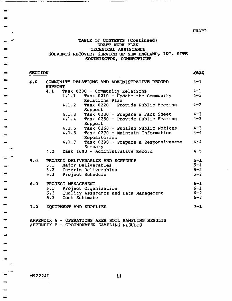
DRAFT
TABLE OF CONTENTS (Continued) DRAFT WORK PLAN
TECHNICAL ASSISTANCE SOLVENTS RECOVERY SERVICE OF NEW ENGLAND INC SITE
SOUTHINGTON CONNECTICUT
TABLES
NUMBER PAGE
2-1 RANGE OF DETECTED CONTAMINANTS 2-23 3-1 EECA REPORT OUTLINE 3-17
FIGURES
N U M B E R PAGE
2-- 1 (GENERAL SITE LOCATION 2-2 2--2 1STUDY AREA 2-3 2--3 FORMER OPERATIONS AREA FEATURES 2-9 2--4 ICURRENT OPERATIONS AREA FEATURES 2-14 2-- 5 1OPERATIONS AREA VOCs IN SOIL 2-26 2--6 VOCs IN OVERBURDEN AQUIFER 2-28 2--7 VOCs IN BEDROCK AQUIFER 2-29 5--1 PROJECT SCHEDULE 5-3 6--1 PROJECT ORGANIZATION 6-3
W92224D iii
1
10
DRAFT
INTRODUCTION
At the request of the US Environmental Protection Agency (EPA)
Region I HALLIBURTON NUS Environmental Corporation (HNUS) will
provide technical assistance for a rapid remedial action at the
Solvents Recovery Service of New England Inc (SRSNE) site in
Southington Connecticut This technical assistance involves the
performance of an Engineering EvaluationCost Analysis (EECA) to
evaluate rapid remedial action alternatives and preparation of an
EECA Report The technical assistance also involves provision of
community relations and administrative record support and design
and implementation of the selected rapid remedial action This
Work Plan was developed based on the EPA Statement of Work (SOW)
dated April 24 1992 the scoping meeting of June 4 1992 and the
results of discussions with the RPM The work was authorized under
Work Assignment Number 30-1R08
HNUS understands that the overall objective of the rapid remedial
action at the SRSNE site is to accelerate the site remediation
process and control the migration of contaminants through mass
removal of known contaminants from soils and groundwater To
achieve this overall objective EPAs specific goals are to
accomplish the following
W92224D 1-1
DRAFT
1 Dewater the Operations Area or portions of the Operations
Area as appropriate to allow work to proceed on the
contaminated soils
2 Initiate removal of Volatile Organic Compounds (VOCs)
from soils through in-situ treatment and
3 Install and operate an appropriate water treatment system
that does not result in unacceptable air emissions This
water treatment system will be designed to address
contaminated groundwater and potential vapors which may
be generated from dewatering and treatment of the soil
An EECA is required to provide the EPA with the necessary
technical cost and risk information to develop evaluate and
select the most appropriate options for fulfilling each of these
objectives An EECA Report records this comparative analytical
process and is required for a rapid remedial (non-time-critical
removal) action
This Technical Assistance Work Assignment will be performed
consistent with the requirements of the following documents the
National Contingency Plan (NCP) the Comprehensive Environmental
Response Compensation and Liability Act (CERCLA) of 1980 as
amended by the Superfund Amendments and Reauthorization Act (SARA)
W92224D 1-2
DRAFT
of 1986 and the EPA SOW HNUS will utilize to the extent
appropriate the Draft Engineering EvaluationCost Analysis
Guidance for Non-Time-Critical Removal Actions (June 1987) the
revised Outline of EECA Guidance (March 30 1988) The Role
of Expedited Response Actions Under SARA (April 21 1987) (OSWER
Directive 93600-15) and other information and guidance on
conducting rapid remedial actions which EPA provides in writing
during the period of this assignment At the direction of the RPM
the contractor will also consult with experts in the Environmental
Services Division in EPA Region I and in the Emergency Response
Division within the Office of Emergency and Remedial Response for
assistance in planning and preparing the EECA and in implementing
the rapid remedial action
This Work Plan presents the technical scope of work and proposed
schedule for preparing the EECA and providing community relations
and administrative record support It addresses the initial design
of the rapid remedial action but does not address implementation
of the rapid remedial action which may be the subject of an
amended SOW and a subsequent amendment to this work plan This
Draft Work Plan contains seven sections Section 10 provides an
introduction Section 20 summarizes the site history and existing
site data Section 30 details the tasks to be undertaken in the
analysis of rapid remedial action alternatives and in the
preparation of a draft EECA Report Section 40 describes the
bullraquolaquo W92224D 1-3
DRAFT
tasks to be undertaken to support the community relations and
administrative record requirements of the EECA process Section
50 describes anticipated interim deliverables and the schedule for
the work Section 60 provides a proposed project management
approach and Section 70 identifies the equipment and consumable
supplies that may be required to perform the activities identified
in the Draft Work Plan
W92224D 1-4
DRAFT
20 SITE DESCRIPTION AND BACKGROUND
A summary of the site area history and physical and chemical
characterization is provided in the following text
21 Site Area Description
The Solvents Recovery Service of New England (SRSNE) National
Priorities List (NPL) Superfund site is located on Lazy Lane in the
Town of Southington Connecticut in Hartford County approximately
15 miles southwest of Hartford Figure 2-1 shows the general
location of the SRSNE Inc facility (Operations Area) with respect
to the Town of Southington and its environs The NPL study area
(Figure 2-2) for the SRSNE facility includes the adjoining property
to the east known as the former Cianci property the Town of
Southington well field and the lot formerly occupied by the Queen
Street Diner on the eastern side of the Quinnipiac River The
EECA analysis and subsequent removal action will for the most part
be confined to the Operations Area itself
W92224D 2-1
DRAFT
000 r c r
SOURCE US OEOLOOICAL SURVEY 75 MINUTE SERIES TOFOORAFHIC MAPS CONNECHCUT QUADRANOLES
(SOUTHINGTON 196S PHCTTOREVISED 19lt4 MERIDEN 1967PR 19M NEW BRITAIN 1966 PR 1984 B R i n O L 1966 FT 1984)
FIGURE 2-1 CONNEQICUT
LOCATION MAP SOLVENTS RECOVERY SERVICE OF NEW ENGLAND INC SITE
SOUTHINGTON CONNECTICUT OUAORANGtX LOCATION
2 -2 W92224D
DRAFT
SOLVENTS RECOVERY SERVICEshyOF NEW ENGLAND INC
LEGEND SRSNE PROPERTY UNE
bulllaquoKlaquo^
APPROXIMATC SCALE IN FEET FIGURE 2-2 STUDY AREA MAP
SRSNE INC SITE AND TOWN PRODUCTION WELLS SOUTHINGTON CONNECTICUT
DRAFT
SRSNE Operations Area - The Operations Area occupies approximately
25 acres and consists of the grounds and structures within the
fenced perimeter where the day-to-day drum storage and fuel
blending operations were conducted prior to April 1991 The lot
owned by SRSNE occupies 37 acres and includes the Operations Area
and the access road leading to Lazy Lane
The Operations Area is located in the Quinnipiac River basin
approximately 600 feet west of the river channel This lot is
situated just south of Lazy Lane and the Mickeys Garage property
The ground surface elevation ranges between approximately 164 and
180 feet above mean sea level (MSL) The majority of the
Operations Area where day-to-day activities occurred is level (166
- 168 feet MSL) A steep hill (maximum elevation of 180 feet MSL)
occupies the west and southwest portions of the property
Just to the east of the Operations Area outside of the chain-link
fence is an unlined drainage ditch which carries treated effluent
from the cooling towerair stripper to the Quinnipiac River
West of the Operations Area - Immediately uphill and west of the
SRSNE Operations Area is the S Yorski property which has a house
and several tracts of land used for farming Only private
residences are situated farther west of the Yorski property A
number of private residences are located to the southwest of the
W92224D 2-4 ~ bull
DRAFT
Study area in the vicinity of Curtiss Street and in the upland
areas
To the west the ground surface elevation increases steadily to a
maximum of 280 feet MSL along Lazy Lane approximately 2200 feet
west of the Operations Area
North of the Operations Area - Immediately north of the SRSNE
Operations Area is the Mickeys Garage auto body repair shop
located on Lazy Lane Several tracts of undeveloped land and two
ponds are located north of Lazy Lane This area extends
approximately to Interstate Highway 1-84 One private residence is
situated northeast of the Operations Area across from the former
Cianci property
North of the study area the Quinnipiac River channel turns
northwest (the river flows from north to south) and passes under Ishy
84 This area is generally in the 150-170 foot MSL elevation
range One ridge possibly a former roadway rises to a peak
elevation of 180 feet MSL (approximately 300 feet north of Lazy
Lane)
East of the Operations Area - The SRSNE facility is bordered on the
east by the Boston amp Maine (BampM) right-of-way and the former Cianci
property The Quinnipiac River borders the eastern edge of the
W92224D 2-5
DRAFT
former Cianci property The former Cianci property currently
owned by SRSNE has never been developed and has been altered by
past earth moving and leveling activities Wetlands which occupied
this area have been filled Some wetlands remain as do those in
the floodplain of the Quinnipiac River An unpaved access road
traverses from north to south through the Cianci property and into
the Town well field property
The Cianci property is a well-vegetated level lot characterized by
open grassy fields and some wetlands Surface elevations range
from 150 feet MSL (at the floodplain) to about 160 feet MSL near
the BampM railroad tracks
A number of commercial operations including auto body and repair
shops gasoline stations stores and restaurants are located on
Route 10 (Queen Street) due east of the Quinnipiac River Route 10
serves as a major thoroughfare through the Town of Southington
Residential dwellings are situated uphill and east of Queen Street
The ground elevation increases east of Queen Street to
approximately 250 to 300 feet MSL
South of the Operations Area - Due south of the former Cianci
property and southeast of the Operations Area is the Town of
Southington well field property which consists of approximately
282 acres of undeveloped land Town Production Wells Nos 4 and
W92224D 2-6
22
DRAFT
6 are located approximately 2000 and 1400 feet south of the SRSNE
property respectively The Quinnipiac River flows southward along
the eastern edge of the former Cianci property and a portion of the
Town well field and between Wells 4 and 6
The Town well field is characterized by open grassy fields in
gently rolling terrain Wetlands are present in the proximity of
the River Ground elevations range between 145 feet MSL (in the
floodplain near Well No 6) to 160 feet MSL at the peak of one
hill A seasonal pondwetland occupies an area encompassing
portions of the Cianci property and the north portion of the Town
well field A Connecticut Light amp Power (CLampP) easement for a high
tension electric transmission line is located in the northern
portion of the Town well field property (in a northwest-southeast
orientation)
Site History and Contaminant Source Identification
SRSNE Inc began operations in Southington in 1955 The facility
received spent industrial solvents which were distilled for reuse
as solvents or blended with fuel oil for use as a hazardous fuel
product The facility was permanently closed in May 1991
W92224D 2-7
DRAFT
While the SRSNE Inc facility operated various practices resulted
in the discharge of spent solvents into the soils and groundwater
These practices included disposing distillation sludges in unlined
lagoons burning sludges in an open-pit and spilling spent
solvents during handling storage and loading activities within
the Operations Area The remainder of this section presents a
summary of the potential contaminant source areas in the Operations
Area Both former (pre-1980) and current (post-1980) facility
features are presented
221 Former Features
Some of the historical information for the contaminant source areas
is based on an interpretation of one set of aerial photographs by
the EPA Environmental Photographic Interpretation Center (EPIC)
(1988) Information developed by other investigators was used to
supplement the interpretation of the aerial photographs Figure 2shy
3 presents the former features described in this section
Operations Building - The 1951 and 1957 aerial photographs of the
area show the concrete block operations building Three
distillation pots and a distillation column were located adjacent
to the operations building in the process area These facilities
were used to separate recoverable fractions from the spent
solvents Aqueous wastes from the distillation process were
W92224D 2-8
I i E I 1 f I f I i f 1 i i 1 1 t I I I i I I 1 I i I i I I I I I
LEGEND
I I TANK raquoraquo laquocw
Q ) MEll POWT CR CHAUaU
-raquomdashlaquomdashraquoshy CHAM UNK f lNCt
PROPMTY UNC UO
H 1 h RANJIOAO IRACXS SCMC M TOT
FIGURE 2-3 FORMER MAJOR FEATURES AT THE
SRSNE INC SITE OPERATIONS AREA
DRAFT
discharged to an unspecified on-site location(s) Still bottom
sludges were discharged into two unlined lagoons discussed below
(EPA FIT EampE 1980)
Primary and Secondary Lagoons - These lagoons apparently installed
after 1957 were first identified in an April 1965 aerial
photograph The primary lagoon was located immediately south of
the operations building The secondary lagoon (which appears to be
two earthen excavations separated by a berm) was located 120 feet
south-southeast of the operations building Both lagoons are no
longer present having been covered with soil
The facility disposed of distillation bottoms in the primary lagoon
situated adjacent to the process area Overflow from the primary
lagoon was directed to the secondary lagoon Overflow from the
secondary lagoon would flow to the drainage ditch adjacent to the
railroad tracks and subsequently into the Cianci property (EPA FIT
E amp E 1980)
Open Pit Incinerator - The 1967 photograph showed a walled open
pit located in the southeastern corner of the property This pit
was present in the 1970 1975 1980 and 1982 aerial photographs of
the study area The still bottoms were burned in the open pit
after disposal in the lagoons stopped This open burning practice
was discontinued some time in the late 1960s or early 1970s
W92224D 2-10
DRAFT
In the 1975 photograph the EPIC analysis indicated that a tank
truck was parked adjacent to the pit where it appeared to discharge
its contents A large pool of liquid is visible at the
northeastern corner of the pit draining into the ditch paralleling
the railroad tracks
Tank Farm - The 1965 aerial photograph indicated the presence of
three horizontal tanks south of the operations building and the
primary lagoon A retaining wall was visible in the 1975
photograph By 1980 there were 19 tanks in the tank farm This
tank farm was located in the western part of the property on the
slope of the hill Five vertical tanks were also identified
adjacent to the operations building in the 1982 photograph
Drum Storage Pad - Drums were first identified in the 1965
photograph Later photos (taken in 1970 1975 1980 and 1982)
indicate that the property was used extensively with numerous 55shy
gallon drums stationary tanks and tank trailers distributed
throughout While these later photos show no obvious stains or
pools of liquid there were no secondary containment structures
visible around the drum or trailer storage areas to collect leaking
materials
W92224D 2-11
DRAFT
Septic Leach Field - The leaching field was not shown on the aerial
photographs although records indicate that one existed for the
sanitary facilities located in the operations building This
leaching field was located to the east of the operations building
and was likely installed after the operations building was
constructed The CT DEP identified the presence of VOCs in samples
collected from the leach field The CT DEP also theorized that
spent solvents may have been disposed of in the septic system
General - The aerial photographs indicated that during the site
development the terrain was altered from a sloping land area to a
flat parking and storage area with a steeply cut embankment It is
apparent from the present terrain of the site that a substantial
volume of soil was excavated and removed from the property to
accommodate such a large flat surface Surface drainage from the
site appeared to flow to the east into the drainage ditch along
the railroad bed and through the culvert to the former Cianci
property The 1970 photograph showed an unpaved access road that
lead to the northwestern corner of the Operations Area The 1975
photograph showed that access to the facility was through a roadway
leading to the northeastern corner of the property parallel to the
railroad tracks The 1982 photograph identified the presence of a
security fence encircling the perimeter of the facility
W92224D 2-12
DRAFT
^ 222 Current Features
Since 1980 SRSNE made modifications to the facility structures
Figure 2-4 depicts the structures and features that remain at the
Operations Area
Office Trailer - An office trailer with a false foundation was
erected during the mid-1980s It is located inside the first
electric gate A second electric slide gate controls access into
the Operations Area The security fences and gates are intact and
in good condition A small parking area abutting the office
trailer was paved The entire truck parking and transfer area
within the Operations Area was paved with asphalt in early 1990
Operations Building - The operations building houses a warehouse
area a mechanical room with a large boiler the cooling towerair
stripper an office and a worker rest area
Tank Farm - The tank farm has four horizontal tanks remaining and
is protected by a concrete containment berm Two vertical blending
tanks are located in the process area adjacent to the operations
building A small sheet metal shed was constructed between the
operations building and the blending tanks drums were opened and
processed at this location
W92224D 2-13
vo
M
a
lECUlU
0 EIlHACnOH raquolaquou
HI bull shy bull CIIAItl UNK FENCf
| I I RAtROAO IRACKS
tvgt
--^-laquolaquoa^) f ^ RIQI
scAu M n t t
FIGURE 2-4 oCURRENT FEATURES AT THE
SRSNE INC SITE OPERATIONS AREA
^ bull i I l l l i l i l t l l l i f l l l l l f l l l l l I I
DRAFT
Drum Storage Area - Two drum storage areas were constructed with
coated concrete containments and a spill collection system
Following cessation of facility activities all drums were removed
from the property
Open Pit Incinerator - The open pit was removed from service during
the late-1960s and early-1970s even though the structure remained
at the Operations Area through 1982 (as seen in aerial
photographs) Following that time the open pit was dismantled and
the foundation was covered
On-site Interceptor System - This system was installed in 1985
along the southern and eastern perimeter of the property This
system consists of 25 extraction wells which pump groundwater to
the cooling towerair stripper on the roof of the operations
building The groundwater is air stripped of volatile organic
compounds (VOCs) and the treated effluent is discharged to a buried
pipe and then into an unlined drainage ditch The effluent crosses
under the railroad tracks through a culvert enters a second buried
culvert in the former Cianci property and exits to the Quinnipiac
River The cooling tower VOC emissions are discharged to the
atmosphere In 1989 three additional extraction wells were
installed to compensate for the lack of performance of the original
system This system remains in operation
W92224D 2-15
23
DRAFT
General - The fuel and chemical piping and valve systems are still
connected to the tanks on the site Chemical residue may still be
present in these pipes
The hillsides on the western portions of the Operations Area are
covered with 2-3 inches of crushed stone There is a knoll on the
southwestern corner of the property which is vegetated with small
trees and brush A small quantity of construction debris was
deposited in this area by SRSNE when the facility was active The
debris remains on-site
Site Characterization
This section describes the site conditions based on information
provided to date through the Remedial Investigation (RI) process
This characterization centers around the Operations Area and
includes a description of the geologic and hydrogeologic setting
and well as the nature and extent of known contamination A more
detailed discussion of the known site characteristics may be found
in the SRSNE Phase 2 Technical Memorandum Remedial Investigation
Feasibility Study (HNUS June 1992)
W92224D 2-16
DRAFT
231 Site Geology
The geology underlying the study area consists of three distinct
units
o Stratified outwash deposits consisting of interbeds of
thin silt silty sand and sand layers These units
underlie approximately 90 percent of the study area The
water table aquifer downgradient of the Operations Area
is located in these stratified deposits The groundwater
and accompanying contaminants migrate through these
deposits to the east and southeast of the Operations
Area
o Basal till consisting of an unstratified poorly sorted
mix of clay silt sand gravel cobbles and boulders
The till varies in thickness and is absent in several
locations within the study area Where the till is
present it may act as a semi-confining layer to
groundwater flow between the more permeable overlying
soils and the bedrock aquifer Till windows allow direct
communication of groundwater from one aquifer to another
W92224D 2-17
DRAFT
o Bedrock beneath the till deposits is a poorly cemented
highly fractured arkosic sandstone The arkosic
sandstone is intruded by a vertically fractured diabase
dike The bedrock surface mapped by seismic refraction
and confirmed by rock coring indicates that a gentle
slope dips east and south towards the Quinnipiac River
and the Production Well No 6 respectively Groundwater
flows primarily through the upper fractured zones but
may also enter deeper into the bedrock through fractures
and joints
232 Hydrogeologic Characterization
The study area groundwater flow is not presently influenced by
Production Wells Nos 4 and 6 which have been inactive since 1979
Therefore groundwater flow conditions observed during the RI
investigations do not represent the groundwater flow
characteristics when the Production Wells were active (pre-1979)
The RI investigations to date identified two aquifers a water
table aquifer and a semi-confined bedrock aquifer The two
aquifers were bounded on the bottom and top respectively by a till
aquitard
W92224D 2-18
DRAFT
There are various hydrogeologic characteristics of the study area
o Two principal aquifers the water table and bedrock
aquifers have been delineated within the study area In
addition to a shallow bedrock aquifer data indicates
that a deep bedrock aquifer may also be present
o Lateral contaminant migration pathways exist in both
water table and the bedrock aquifers
o Groundwater flow in the water table aquifer is generally
to the east (Quinnipiac River) and southeast (Town well
field) of the Operations Area
o Groundwater in the shallow bedrock aquifer flows radially
away from the Operations Area towards the Quinnipiac
River and the Town well field
o Both the fractured siltstone beds and the diabase dike in
the bedrock may serve as preferential pathways for
groundwater flow
o The lack of basal till at several study area locations
may allow contaminated groundwater to migrate between the
water table and bedrock aquifers
W92224D 2-19
DRAFT
o Upward and downward vertical hydraulic groundwater
gradients between the bedrock and the water table aquifer
have been observed in several study area well clusters
o The observed changes in vertical hydraulic gradients at
different times of year are likely the result of seasonal
precipitation events and increases in groundwater
recharge Contaminated groundwater may therefore be
communicated between aquifers depending on the time of
year
o The On-site Interceptor System exerts an influence on the
local groundwater flow in the water table aquifer
233 Nature and Extent of Contamination
This section describes the nature and extent of soils contamination
within the Operations Area and groundwater contamination within
and in close proximity to the Operations Area This section
summarizes what is known to date from the RI investigations For
a more detailed analysis of the site contamination refer to the
Phase 2 Technical Memorandum Remedial InvestigationFeasibility
Study (HNUS June 1992)
W92224D 2-20
DRAFT
2331 Soil Contamination
During the RI investigations soil samples were collected and
analyzed to determine the presence of organic and inorganic
contaminants at the Operations Area A review of the results to
date indicates that
o The Operations Area soils are typically contaminated with
an assortment of VOCs SVOCs PCBs and metals The
contamination is the result of past disposal and
operating practices
o The locations within the Operations Area with the highest
detected soil VOC contaminant levels are next to or are
in areas where spent solvents were stored handled or
processed Elevated levels of total VOCs primarily
chlorinated solvents and aromatics were found at most
locations within the Operations Area including the
locations of both former lagoons the former open pit
incinerator the drum processing area adjacent to the
operations building and the former spent solvent
distillation unit and just downgradient (east) of the
tank farm
W92224D 2-21
DRAFT
o Soils with elevated SVOC concentrations were found
adjacent to the former lagoons the process area and the
open pit VOCs in the Operations Area soils were
generally accompanied by SVOCS
o Soils with elevated PCB concentrations were found
adjacent to the operations building the former lagoons
and the open pit
o Two areas with comparatively elevated inorganics
contamination were identified the former open pit and
adjacent to the process area
Table 2-1 presents the range of contaminants detected in soils
within the Operations Area subdivided into categories of
contaminants (VOCs SVOCs Pesticides and PCBs and Inorganics)
Figure 2-5 presents the approximate extent of total VOC
contamination in soils within the Operations Area More detailed
summary tables of the Operations Area soil sampling results by
boring location and a figure indicating those locations are
presented in Appendix A
W92224D 2-22
T A B L E 2 - 1 DRAFT RANGE OF DETECTED CONTAMINANTS
PHASE 2 SAMPLING 1991 OPERATIONS AREA
SRSNE INC SITE SOUTHINGTON CONNECTICUT
C T D H S STDS (utf l )
2
1000
7
1
200 5
5 5
I
10 5
1000
MCL
2
7
100 70
5
200 5
5 5
5
5
1000 700 100
10000
VOLATILE ORGANIC
COMPOUNDS
Methylene Chloride Vinyl Chloride Chloroethane Acetone 2 - Butanone Carbon Disulfide 11-Dichloroethene 11 - Dichloroethane
U-Dlchloroethenc (TOTAL) transmdash12-dichloroethene cis-l2-Dichlorocthene Chloroform 12-Dichlorocthane
111-Trichloroethane Carbon Tetrachloride Vinyl Acetate
12mdashDichloropropane Trichloroethene 112 -Trichloroethane Benzene 2-Hexanone 4-Methvl-2-penianone trans-l3-Dichloropropene Tetrachloroethene 1112-Tetrachlorocthane Toluene Ethylbenzene Styrene Xylene (total) Isopropyl benzene n-propylbenzene 135 -Trimethylbenzene 124-Trimethyl benzene
12 Dibromo 3-Chloropropane
SUBSURFACE SOILS | OVERBURDEN GW | BEDROCK GW | MIN MAX MIN MAX MIN MAX
ueke ueI ue1 uitl 8600J
360 J SJ 6201 SJF 8 J SF smiamsmshy100 + llOOJ 2 J 9500 J R R R R
22 38000 R R R R R R R R
430 J 1300 3 2 0 3 S F 15000 J S F bullimrsFii imaamF 325 790 J 290 J 5500 J 945 J 940J
9 79000 J 08 J
2 5 0 0 J F 110000 J F 275J F 5300J F 680J
940J SF bull - bull i 3 j s - -
275 J + 690000 78000 J SF 240000 J S F 17000 J SE 32000OJ SF 290J SF 9100 J SF 6 9 J J SE 2000J SJf
4J
220 J 07 J 146J + 800000 26000 J SF 300003 SF 14 J SF 41000J SK 910 J 2900 47 J
255 J + 650 J 610J SF ^bulliiimms-shyllOOJ 7900 J R R R R 410 J 130000J 22000 J 225 2100 J
3903 S 200 J 440000 2000 J SF 46 J 64003 SE
183 6 1700000 J 81000 J SF 1500003 S f 21 3800000 870 J F 60000J F 51J 7403 F
12000 2500000 49000J F 97 J 35 760000 4353
1200J 13 083
13
950 J 26 J 7103
R
Notes
(+) The sample was averaged wilh its duplicate = Value was rejected Medium level sample = Exceeds Connecticut DHS Standards bullbull Value is estimated = Exceeds Federal MCLs
W92224D 2-23
TABLE 2-1 (continued) RANGE OF DETECTED CONTAMINANTS PHASE 2 SAMPLING 1991 OPERATIONS AREA SRSNE INC SITE SOUTHINGTON CONNECTICUT Page 2
DRAFT
CTDHS MCLi SEMIVOLATILE SUBSURFACE SOILS | OVERBURDEN GW I BEDROCK GW I STDS (bulllaquofl) COMPOUND MIN MAX MIN MAX MIN MAX (bulllaquofl) bullgklaquo bullgkg bullgA bullgn bullgfl -grt
PHENOL 180 J 680J 22 4200 14 600 U - DICHLOROBENZENE 2J
75 75 14-DICHLOROBENZENE 10 600 12-DICHLOROBENZENE ISOJ 30
2-METHYLPHENOL 170 J 420 J 14 83 12 16 4-METHYLPHENOL 260J 280J 14 100 4J 13 ISOPHORONE 220J 700 J 8J 2J 9J BENZOIC ACID 870 J 24-DIMETHYLPHENOL 7J 11 2J 124-TRICHLOROBENZENE no J 530 J NAPHTHALENE 140 J 3300 J 3J 44 2J 3J 4-CHLORANIUNE 940 J 1900 J 4-CHLORO-3-METHYLPHENOL 2800J 16 2 - METH YLNAPHTHALENE 200J 2000J 3J DIMETHYL PHTHALATE 73 J 74 J 2J 17 3-NITROANILINE R R ACENAPHTHENE 170 J DIBENZOFURAN 110 J 24-DlNITROPHENOL 6J DIETHYL PHTHALATE 140 J 1600 J 2J 5 4-NITROANILlNE R R FLUORENE 69 J 160 J PHENANTHRENE 130 J 119$ J + IOJ ANTHRACENE 64J 190 J DI-N - BUTYLPHTHALATE S3 J S700J I J 52 J 3J FLUORANTHENE 61 J 470 J PYRENE 48J 270 J BUTYLBENZYLPHTHALATE 100 J 8600J 9J 63 J BENZO(a)ANTHRACENE 130 J CHRYSENE 89 J 220J BIS(2-ETHYLHEXYL)PHTHALATE 200J + 120000 J 11000
I DI shy N shy OCTYLPHTHALATE 580 J 1450 J + 26 J
CTDHS MCLi PESTICIDESPCB SUBSURFACE SOIL | OVERBURDEN GW | BEDROCK GW I STDS (bullgfl) COMPOUNDS MIN MAX MIN MAX MIN MAX
OKI) bullJtklt bullgkg bullRl bullg1 bullgl bullgl AROCLOR 1016 27 J 1200 J AROCLOR 1248 1550 +
1 05 AROCLOR 1254 380J 13000 J 13 SF
1 05 AROCLOR 1260 160 J 9700 J 85 SF
Notes
( + ) = The sample was averaged wilh its duplicate = Value was rejected = Medium level sample = Exceeds Connecticut DHS Standards = Value is estimated = Exceeds Federal MCLs
W92224D 2-24
DRAFT TABLE 2 -1 (continued) RANGE OF DETECTED CONTAMINANTS PHASE 2 SAMPLING 1991 OPERATIONS AREA SRSNE INC SITE SOUTHINGTON CONNECTICUT Page 3
C T D H S MCLi INORGANIC SUBSURFACE SOILS | OVERBURDEN GW | BEDROCK GW |
STDS (bullgl) COMPOUNDS MIN MAX FILTERED MIN MAX MIN MAX
(bullgl) bullg kg -gkg SAMPLE P - 4 B bullgl bullgl bullgl bullgl ALUMINUM 3150 10400 + 356 12200 51700 906 71300 ANTIMONY R
50 ARSENIC 050 J 54 20 J 50 210 40 J 80 J 1000 2000 BARIUM 341 J 1480 280 604 3510 J SF 106 ^269eJSFfshy
BERYLLIUM 032 J 085 11 J 54 J 19 J 85 J 5 5 CADMIUM 417 389 26 J 769 SF 425 J
CALCIUM 631 J 9410-1shy 65100 37100 349000 41850 J 140000 50 100 CHROMIUM 72 183 512 S U11SF bull 114J SF rfampSiF
COBALT 29 99 524 196 140 104 267 J J 1000 1300 COPPER 50 104 J 104 441 J 324 56 imi SF
IRON 3980 13700 7350 39100 84400 1930 99850 J 1$ 15 LEAD 53 J 1750 J 280 J SF 175 SF 53 bull -scim-sF^i
MAGNESIUM 1140J 5330 3360 9540 25700 1490 33400 5000 MANGANESE 752 J 440 J 6720 S 7610 S 37200 S 455 4000 J
2 2 MERCURY 035 J NICKEL 57 199 324 J 843 101 1022 J POTASSIUM 433 J 2250 5940 14000 J 12465 J 19600 J
10 50 SELENIUM 17 + 373 J 20000 SODIUM 699 4115-f 12600 10100 105000 J S 6320 16910 J
VANADIUM 101 J 309 381 J 114 328 152 ZINC 192 J 171 J 476 J 662 151 393 J 893
DIOXINSFURANS SUBSURFACE SOILS
COMPOUND MIN MAX
bullgkg bullgkg 2 37 8 - TCDD Equivalents 001 030
Notes
( + ) The sample was averaged with its duplicate = Value was rejected Medium level sample = Exceeds Connecticut DHS Standards Value is estimated = Exceeds Federal MCLs
W92224D 2-25
vo
Ngt rsgt
a reg
to
N
^laquo I ICHtV
reg SOIL SAUPIING LOCATIOM shy MUS PHASE 2 1 t9 l
SOIL SAMPLING LOCATION shy CPA TAT 1
B-9
1344400
bull bull bull
( T ) mdash -
mdash SAMPLE LOCATION IDENTIFIER
mdash TOTAL voca IN SOa ( U Q A B )
ESnwAlEO AREA Of SOIL CONTAMINAIKM
EIL POINT OR CHAUBOI
NOTE All LOCAHONS ARpound APPROXIMATE FOUR CPA TAT SAHPtC LOCAltONS (1SB8) ARC iNauoro IN AREAS MOT SAMPIEO BY NUS IN I M I
FIGURE 2-5 TOTAL VOCs IN SOIL OPERATIONS AREA 1991
SRSNE INC SITE SOUTHINGTON CONNECTICUT
60 120
3SCALE IN FEET ALL LOCATIONS ARE APPROXIMATE
O
i 1 I 1 I f l l l l l f l l l l l l l l i l l l f l l l i l l l i i
DRAFT
2332 Groundwater Contamination
The RI investigations to date have provided information on the
contaminant presence and distribution in the water table and
bedrock aquifers The observed contamination pattern is based on
the current non-pumping conditions of Wells Nos 4 and 6 Table
2-1 presents the range of contaminants detected in groundwater
within the Operations Area subdivided into categories of
contaminants (VOCs SVOCs Pesticides and PCBs and Inorganics)
The water table and bedrock aquifers are presented separately
Figure 2-6 presents the approximate extent of total VOC
contamination in the overburden aquifer Figure 2-7 presents the
approximate extent of total VOC contamination in the bedrock
aquifer More detailed summary tables of the Operations Area
groundwater sampling results are presented in Appendix B
Water Table Aquifer
For the overburden aquifer information to date indicates that
o VOC contaminants in groundwater are migrating away from
the Operations Area towards the Quinnipiac River and Town
well field The highest concentration of VOCs was
detected in Operations Area groundwater samples
V
W92224D 2-27
o ro ro
regro bull 1 ^ O
- mdashshyraquolaquo RWr Of WAY
IO I
IO 00
^ M W - 1 2 3 C asoJ
M W - 7 A ^JO
APPROXIMATE SCALE IN FEET
oFIGURE 2-6 TOTAL VOCs IN OVERBURDEN AQUIFER
SRSNE INC SITE SOUTHINGTON CONNECTICUT
P I- 1 f i l l f l I I I I i i I I I I f l l i I I i i 1 f 1
DRAFT
lt in
hshyD g1shy
az oin u UJ zD zo o
z^9 1 Q 5
IGU
RE
2
IN B
EDR
O
UTH
INi
U 0) O
sect - J
i O K
w Il l
W
d z^ UJ zwtr CO
W92224D 2-29
DRAFT
o At the Operations Area the highest levels of VOCs and
SVOCs in groundwater were detected primarily near the
former secondary lagoon and the tank farm The On-Site
Interceptor System) OIS may be limiting dispersion of
contaminants by inducing groundwater flow toward one
primary extraction well
o PCBs were detected in groundwater samples collected from
the P-IA and B well cluster in the Operations Area The
presence of numerous solvents and some surfactants may
have caused the PCBs to partition to the aqueous phase
o Groundwater contaminants observed at the Operations Area
and at downgradient locations have been identified by
SRSNE in NPDES reports and in the list of chemicals the
facility typically handled
o Contaminated groundwater with elevated concentrations of
VOCs and SVOCs appears to flow east from the Operations
Area to the Quinnipiac River along a limited path
o Groundwater contamination from the water table aquifer
appears to enter the shallow bedrock aquifer through the
till window present in the Operations Area The vertical
gradients observed support this conclusion
W92224D 2-30
DRAFT
o The presence of non-aqueous phase liquids may allow
transport of VOC contaminants in directions other than
that of groundwater flow
Bedrock Aquifer
For the bedrock aquifer information collected to date indicates
that
o VOC contaminants have been identified in all shallow
bedrock wells downgradient of the Operations Area
indicating that contaminant migration is pervasive in the
bedrock aquifer
o The shallow bedrock is more contaminated by VOCs than the
deep bedrock Vertical gradients indicate the potential
for contaminant penetration to deeper fractures from the
shallow bedrock The presence of VOCs in both the
shallow and deep bedrock supports this conclusion The
extent of contamination in the deep bedrock is unknown
because of the limited data available
o Contaminated groundwater at the Operations Area appears
to enter the shallow bedrock through a till window
adjacent to the tank farm and process area
W92224D 2-31
DRAFT
o Contaminated groundwater can migrate a substantial
distance downgradient in the fractured bedrock At some
well locations where the till is absent groundwater in
the shallow bedrock well is more contaminated by VOCs
than the corresponding overburden well
o Bedrock wells immediately upgradient (west) of the
Operations Area have low levels of VOC contamination
The presence of VOCs may have occurred because of some
other transport mechanism such as diffusion
W92224D 2-32
30
DRAFT
SCOPE OF THE RAPID REMEDIAL ACTION SUPPORT
An Engineering Evaluation and Cost Analysis will be prepared using
data developed from previous RI work and from preliminary risk
assessment and groundwater evaluations The EECA work assignment
will encompass a total of eight tasks Community relations (Task
0200) and administrative record (Task 1600) support are required as
part of the EECA process and are discussed in Section 40 of this
work plan The remaining EECA evaluation and report preparation
tasks include
o Task 0100 - Project Planning
o Task 0500 - Dewatering Evaluation
o Task 0600 - Contaminants Assessment
o Task 1000 - Rapid Remedial Alternatives Evaluation
o Task 1100 - EECA Report
o Task 1200 - Post EECA Support
The overall objective of the EECA is to develop and evaluate rapid
remedial action alternatives that will lead to the fulfillment of
the remedial action objectives described in Section 10 of this
Work Plan For purposes of this Work Plan a rapid remedial action
is equivalent to a removal action for which a planning period of at
least six months exists before on-site activities must be
W92224D 3-1
31
DRAFT
initiated consistent with subpart E of the NCP (40 CFR Part
300415(b)(4))
The following sections provide technical discussions regarding the
components of each EECA task Task numbers coincide with the
standardized tasks defined in the EPA RIFS guidance
Task 0100 - Project Planning
This task will include attending a scoping meeting reviewing
existing information and guidances identifying the scope of the
EECA preparing the Work Plan and Detailed Cost Estimate and
reporting to EPA on the progress of the work Because no field
work is anticipated under this work assignment preparation of
amended Sampling and Analysis (SAP) and Health and Safety (HASP)
Plans will not be included in this work plan If EPA requests
field implementation in the future then an amended work plan will
subsequently be prepared which will include preparation of an
amended SAP and HASP
The Work Plan provides an overview of the technical project
management and scheduling aspects for the EECA A scoping
meeting was held with EPA on June 4 1992 to discuss significant
issues for the EECA It is anticipated that up to five additional
progress or planning meetings with EPA may be required
W92224D 3-2
DRAFT
This task also includes preparation of monthly progress reports
which will include a narrative description of the status of each
task as well as a financial summary
311 Work Plan and Cost Estimate Preparation
This Work Plan presents a summary of information for the SRSNE site
including a site description potential sources of contamination
on-site objectives of the EECA the scope of the EECA the
project management approach and a project schedule The Work Plan
provides an overview of how the project will be managed and the
types of activities to be conducted The detailed Cost Estimate
will present the Level of Effort hours and costs (including Other
Direct Costs and subcontractor services) required to implement the
Work Plan It is anticipated that EPA will review and prepare
comments within two weeks of receipt of the draft Work Plan After
receipt of the comments HNUS will prepare a Final Work Plan and
Cost Estimate
Up to ten copies of the draft and final versions of the Work Plan
and three copies (draft and final) of the Cost Estimates will be
provided to EPA
W92224D 3-3
32
DRAFT
Task 0500 - Dewatering Evaluation
A groundwater flow model will be prepared using the USGS MODFLOW
computer model The model will be constructed using data gathered
during the Phase 2 site investigation and from previous
investigations
The model will consist of three layers The first layer will
represent the water table aquifer the second will represent the
glacial till unit and the third layer will represent the upper
fractured bedrock Hydraulic values measured during the prior RI
site investigations will be assigned to their respective layers
The majority of the data collected during the prior investigations
was collected to the east and downgradient of the Operations Area
Because of this the hydrogeologic conditions west of the
Operations Area must be approximated based upon the available data
The hydraulic values assigned to this area will be adjusted within
appropriate limits until the model recreates the measured August
1991 groundwater flow conditions within the Operations Area
A sensitivity analysis will be performed on these assumptions for
model input west of the Operations Area
W92224D 3-4
DRAFT
The model will then be used todetermine the pumping rate number
of wells and well spacing for a dewatering system The objective
of the dewatering system will be to maintain the groundwater
elevation at or below the top of the till or bedrock within the
Operations Area Capital and operating costs of the dewatering
system will be estimated
As part of the conceptual design of the dewatering system the
pumping rate will be determined for three groundwater scenarios
The first is the observed conditions of August 1991 The second is
the October 1991 condition The third condition is one that would
result in the breakout of groundwater at the toe of the slope along
the west boundary of the Operations Area This final scenario is
believed to represent the worst condition and therefore the highest
required pumping rate
The model will also be used to assess the viability of two
implementation options The first option is the use of an
upgradient interceptor trench west of the Operations Area This
trench may be useful in controlling the groundwater elevations
within the Operations Area by intercepting groundwater before it
enters the Operations Area This interception of clean water would
reduce the volume of groundwater requiring treatment The second
option is to dewater the Operations Area in stages (eg successive
W92224D 3-5
33
DRAFT
5 foot depthintervals) to allow a phased implementation of soils
treatment
Finally the model will be used to evaluate the effectiveness of
the existing On-site Interceptor System (OIS) This evaluation
will determine if the existing system can be utilized as a
component of the dewatering system It will also evaluate the
usefulness of continued operation of the OIS during Operations Area
dewatering
At the conclusion of the groundwater data evaluation an interim
report will be prepared The results of the computer analysis will
be presented including the three flow scenarios and the two
implementation options The interim report will describe the
conceptual design of the dewatering system and projected associated
costs It will also identify site access considerations for
installing structures for dewatering and monitoring A total of
three meetings with EPA are anticipated for this task
Task 0600 - Contaminant Assessment
A limited evaluation of soil and groundwater contaminants will be
required for the EECA process Contaminants of concern and
removed cleanup levels will be defined for both the dewatering and
soil treatment segments of the rapid remedial action These
W92224D 3-6
DRAFT
removalcleanup levels will consist of- media-specific goals for
protecting human health and the environment Removal cleanup
levels for soils will be developed based on a short-term
(preliminary) soils risk assessment which will consider
contaminants of concern (VOCs only) and exposure routes and
receptors
The contaminated occurrence and distribution will be reviewed and
chemicals of concern (COCs) selected for the development of removal
clan-up goals for the Operations Area soils The following factors
will be considered in the chemical of concern selection process
o Contaminant concentration in the soils
o Frequency of detection
o Chemical fate and transport (eg chemical volatility
vapor pressure Henrys Law Constant)
o Toxicity
The concentration-toxicity screen (CT-screen) presented in the EPA
Risk Assessment Guidance for Superfund Volume I Human Health
Evaluation Manual (Part A) will be used in the COC selection
process The objective of CT-screen is to identify chemicals in a
particular medium that based on concentrations and toxicity are
most likely to contribute significantly to risks calculated for
exposure scenarios involving that medium so that the risk
W92224D 3-7
DRAFT
assessment is focused on the most significant chemicals
The human exposure scenarios for the preliminary risk analysis will
include
Incidental ingestion of soils by onsite workers
Dermal contact with soils by onsite workers
Inhalation of Soil ParticulatesVapors by onsite
workers
Inhalation of Soil ParticulatesVapors by downwind
residents
Potentially acceptable removal cleanup levels ie levels which
will make the soil safe to excavate and handle during subsequent
remedial actions will be proposed based on the results of this
preliminary soils risk assessment
Removal cleanup levels for groundwater will be developed based on
chemical- and location-specific ARARs and other appropriate risk-
based levels For example effluent discharge limits and
requirements may include the Ambient Water Quality Criteria and the
current SRSNE NPDES permit limits EPA will consult with the CT
DEP and provide further direction to HNUS on developing the
groundwater removal cleanup levels
W92224D 3-8
34
DRAFT
At the conclusion of the contaminant assessment an interim report
will be prepared The results of the short-term (preliminary)
soils risk assessment will be presented The interim report will
also describe the ARARs evaluation for determining the groundwater
removal cleanup levels Included in the interim report will be two
tables one indicating the interim soil chemicals of concern and
the proposed soils removal cleanup levels and the other indicating
the interim groundwater chemicals of concern and proposed
groundwater removal cleanup levels These two tables will need to
be finalized before the rapid remedial action alternatives
evaluation can be concluded As many as four meetings with EPA may
be needed for this task
Task 1000 - Technical Evaluations of Alternatives
The EECA will use data collected during the prior RI field
investigations and the results of the contaminant assessment to
identify a short list of applicable remedial technologies
formulate rapid remedial action alternatives and evaluate these
alternatives for effectiveness implementability and cost The
alternatives will also be examined to determine whether they
contribute to the efficient performance of any anticipated long
term remedial action and comply with Applicable or Relevant and
Appropriate Requirements (ARARs) to the extent practicable
W92224D 3-9
DRAFT
The technical evaluation will be subdivided by media into the
following two subtasks
o Soil Remediation Evaluation
o GroundwaterVapor Remediation Evaluation
These tasks are described in more detail in the following sections
As many as four meetings with EPA may be required to complete this
task
341 Soil Remediation Evaluation
The selection of soil remediation technologies available for the
rapid remedial action is limited to in-situ treatment processes
The short list of in-situ technologies to be considered as given
in the SOW and discussed at the scoping meeting of June 4 1992
includes vapor extraction and thermal desorption in conjunction
with vapor extraction Soil flushing will also be considered if
the results of the evaluation indicate that dewatering the
Operations Area or implementing vapor extraction is impracticable
HNUS will incorporate the technology screening treatability results
developed by EPA ORD Cincinnati Ohio if available in a timely
manner Additional in-situ technologies may be identified by HNUS
and added to the EECA process at the request of the RPM
W92224D 3-10
DRAFT
A conceptual design will be described for each alternative in
sufficient detail to include the location of areas to be treated
approximate volumes of soil to be addressed and potential
locations for required treatment facilities and structures The
definition of each alternative may include preliminary design
calculations process flow diagrams sizing of key components
preliminary site layouts and potential sampling and analysis
requirements For the conceptual design of the vapor extraction
alternative HNUS will consider the description provided by EPA
RSKRL Ada Oklahoma
A detailed analysis of rapid remedial action alternatives will be
performed and will consist of
o A discussion of limitations assumptions and
uncertainties concerning each alternative
o Assessment and summary of each alternative against
evaluation criteria
o Comparative analysis among alternatives to assess the
performance of an alternative relative to each evaluation
criterion
W92224D 3-11
DRAFT
The three primary evaluation criteria developed for non-time
critical removal actions are effectiveness implementability and
cost Two additional criteria the ability of the alternative to
achieve ARARs and to contribute to the performance of the long term
remedial action will also be considered
The effectiveness evaluation will address the extent to which the
completed action can achieve the interim cleanup levels for VOCs in
soils based on making the soils safe to handle during
implementation of the long term remedial action The
implementability evaluation will consider the availability and the
technical and administrative feasibility of the alternative Total
costs of each alternative will be estimated
Applicable or Relevant and Appropriate Requirements (ARARs) will be
considered during the detailed evaluation of alternatives
Alternatives will be assessed on whether they attain ARARs or other
federal and state environmental and public health laws Compliance
with action- chemical- and location-specific ARARs will be
evaluated Each alternative will specify how ARARs are or are not
attained The actual determination of which ARARs are requirements
to be achieved to the extent practicable will be made by the EPA
W92224D 3-12
H ^
DRAFT
The soil treatment alternatives will also be qualitatively examined
to determine the extent to which they contribute to the efficient
performance of any anticipated long term remedial action
Consideration will be given to each alternatives ability to
shorten the duration improve the implementability or reduce the
risks of subsequent soil remedial actions
342 GroundwaterVapor Remediation Evaluation
A preliminary list of applicable technologies for groundwater
remediation at the SRSNE site will be identified based on
information gathered during previous investigations at the site
area The technology types to be used alone or in combination will
be evaluated for applicability to treating both the groundwater
extracted during dewatering and the vapors produced during
treatment of soil
The treatment technologies will then be assembled into a limited
number of rapid remedial action alternatives The temporary
UVoxidation treatment to be installed by CT DEP will be considered
as one of the alternatives A conceptual design will be described
for each alternative in sufficient detail to include the location
of groundwater to be treated or contained approximate volumes of
groundwater to be addressed and potential locations for
interceptor trenches or discharges to surface water The definition
W92224D 3-13
DRAFT
of each alternative may include preliminary design calculations
process flow diagrams sizing of key components preliminary site
layouts and potential sampling and analysis requirements All of
the water treatment alternatives will be appropriately sized to
handle the quantity of water predicted by the dewatering
evaluation
A detailed analysis of rapid remedial action alternatives will then
be performed and will consist of
o A discussion of limitations assumptions and
uncertainties concerning each alternative
o Assessment and summary of each alternative against
evaluation criteria
o Comparative analysis among alternatives to assess the
performance of an alternative relative to each evaluation
criterion
The three primary evaluation criteria developed for non-time
critical removal actions will be effectiveness implementability
and cost Two additional criteria the ability of the alternative
to achieve ARARs and to contribute to the performance of the long
term remedial action will also be considered
W92224D 3-14
DRAFT
The effectiveness evaluation will address the extent to which the
completed action can achieve the interim cleanup levels for the
contaminants of concern in groundwater based on making the
treatment effluent achieve ARARs for discharge to the river The
implementability evaluation will consider the availability and the
technical and administrative feasibility of the alternative Total
costs of each alternative will be estimated Treatment system
operating costs will be limited to the period up until either
interim cleanup levels in soil are achieved or the long terra
remedial action is initiated For planning purposes this is
assumed to be April 1996
In addition to the chemical-specific ARARs incorporated into
establishing the interim cleanup levels ARARs will also be
considered during the detailed evaluation of alternatives
Alternatives will be assessed on whether they attain ARARs or other
federal and state environmental and public health laws Compliance
with action- and location-specific ARARs will be evaluated Each
alternative will specify how ARARs are or are not attained The
actual determination of which ARARs are requirements to be achieved
to the extent practicable will be made by the EPA
The groundwater treatment alternatives will also be qualitatively
examined to determine the extent to which they contribute to the
efficient performance of any anticipated long term remedial action
W92224D 3-15
DRAFT
Consideration will be given to each alternatives ability to serve
as or be incorporated into subsequent remedial actions
35 Task 1100 - Engineering EvaluationCost Analysis Report
A report will be prepared presenting the results of the Engineering
Evaluation and Cost Analysis The EECA Report will discuss the
removal objectives and alternatives considered Each alternative
will be described along with a detailed analysis of how each
addresses the evaluation criteria identified previously
The report will provide a comparative evaluation of all
alternatives in a summary table which highlights findings from the
detailed analysis The purpose of the comparative analysis is to
identify the advantages and disadvantages of each alternative and
to identify key tradeoffs to be evaluated by EPA The format for
the EECA Report is presented in Table 3-1 As many as four
meetings with EPA may be required to complete this task
36 Task 1200 - Post-EECA Support
After the completion of the EECA and publication of the EECA
Report HNUS will assist EPA in preparing design specifications and
drawings for the selected rapid remedial (removal) action During
W92224D 3-16
DRAFT
TABLE 3-1
EECA REPORT OUTLINE
I EXECUTIVE SUMMARY
II SITE CHARACTERIZATION A Site Description B Site Background C Analytical Data D Conditions for the Removal Action
III REMOVAL ACTION OBJECTIVES A Mass Removal of Contaminants B Control of Off-site Migration C Statutory Considerations D Scope and Schedule
IV IDENTIFICATION OF REMOVAL ACTION ALTERNATIVES A Soils Treatment Alternatives B Groundwater Treatment Alternatives
V ANALYSIS OF ALTERNATIVES A Effectiveness B Implementability C Cost D Attainment of ARARs E Contribution to Long Term Action
VI COMPARATIVE ANALYSIS
VII PROPOSED REMOVAL ACTION
W92224D 3-17
DRAFT
this Work Assignment HNUS will prepare and submit a draft final
(90) and final design (100) reports
361 Draft Final Design Report (90)
The Draft Final Design will provide a description of the soil
treatment and groundwater extraction systems groundwater and
vapor treatment systems and discharge conveyance systems The
Draft Final Design will encompass approximately 90 of the total
design effort and a submittal (10 copies) will be forwarded to
the EPA Work Assignment Manager for review and approval
The documents that will be prepared and included in this design
report will include the following
o Introduction
o Basis of Design
Identification of design issues and
uncertainties
A presentation of appropriate waste stream
analytical data including drawings depicting
existing site conditions (physical and
chemical)
W92224D 3-18
DRAFT
Assessment of applicable FederalState
regulations
Technology selection
o Draft final design site construction plans (including
well and equipment and utility citing) flow diagrams
and Process and Instrumentation Diagrams (PID)
o Design analysis including calculations (hydrogeologic
process and civil)
o Technical performance specifications
o Technical construction specifications
o Construction schedule including a suggested sequencing
o Site and remedial system monitoring requirements
o Plant OampM requirements
o A site specific Health and Safety Plan to be
implemented during construction
^ ^ m i t f 0 f
W92224D 3-19
DRAFT
o An assessmentstatement of applicable Federal and State
regulations and permits required to perform the work
o A Bid Form specific to the work to be performed
o Estimated construction cost (+20 to -15)
o Project Delivery Strategy
o Plant Operation and Monitoring Plan (Pilot Study) to
assess variable system operating conditions
As many as four meetings will be held with EPA prior to submittal
to discuss the intended design and scope of the construction
project The intent of these meetings is to minimize potential
revisions required by comments received after the initial
submittal and to expedite submittal of the 100 design report
As many as two meetings will be held with EPA after the submittal
of the 90 design report to discuss EPA comments
W92224D 3-20
DRAFT
362 Final Design (100)
The Final Design Report will revise and complete all deliverables
and will address 100 of the remedial design It is assumed that
the 100 submittal (10 copies) will be provided to EPA within 30
calendar days from receipt of EPA 90 design comments
Deliverables for the 100 design will include
o Final design plans and specifications in reproducible
format (ie mylar or velum drawings hard copy
documents and magnetic media)
o Final technical bid documents
o Final construction schedule
o Final cost estimates
o Identification of additional design
issuesuncertainties including potential long-lead
procurement items
o Final Health and Safety Plan for the remedial action
W92224D 3-21
DRAFT
o Final Plant Operation and Monitoring Plan (Pilot Study)
to assess variable system operating conditions
One meeting will be held with EPA after submittal of the 100
design report
363 Rapid Remedial Action Implementation
This Work Plan does not address activities by HNUS which may be
required for implementation of the removal action
Implementation activities may include
o solicitation and procurement of subcontractor(s)
o subcontractor oversight
o construction quality control
o monitoring
o operation and maintenance
Further description of these implementation tasks and their
respective costs will be provided through amendment to the EPA
Statement of Work and subsequent Work Plan Amendments
W92224D 3-22
DRAFT
40 COMMUNITY RELATIONS AND ADMINISTRATIVE RECORD SUPPORT
Section 415 of the NCP provides for an environmental review and
public participation component to removal actions for which a
planning period of at least six months exists These components
include an establishment of an EECA administrative record and a
public comment period to be held prior to a decision on initiation
of the removal action as well as a response to the public
comments HNUS will assist EPA in these components of the EECA
process A more detailed description of the community relations
and administrative record tasks follows
41 Task 0200 - Community Relations
As specified in the EPA Statement of Work HNUS will provide
additional Community Relations Support during the rapid remedial
(non-time-critical removal) actions These activities are
described as follows
411 Task 0210 - Update the Community Relations Plan
At the direction of EPA HNUS will assist in revising the existing
Community Relations Plan (CRP) to address changes in community
concerns and particular concerns anticipated during the EECA
W92224D 4-1
DRAFT
HNUS may conduct on-site interviews with the interested and
affected residents to ascertain changes in community concerns The
revised CRP may also evaluate which community relations techniques
have been effective and should be continued and recommend
activities to address the rapid remedial action HNUS will provide
draft and draft final copies of the revised CRP to the EPA RPM and
the EPA Superfund Community Relations Coordinator (CRC) Six
copies of the final document will be provided to EPA
One revision of the CRP two meetings with EPA and one trip to the
site area are anticipated for this task
412 Task 0220 - Provide Public Meeting Support
HNUS will provide support for the public informational meeting on
the draft EECA Public meeting support will include attending a
planning meeting with EPA coordinating meeting logistics
preparing audio-visual material attending a dry-run preparing
a list of tough questions attending the informational meeting and
preparing a draft and final meeting summary
A total of two meetings with EPA and one trip to the site area are
anticipated for this task
W92224D 4-2
DRAFT
413 Task 0230 - Prepare a Fact Sheet
HNUS will provide a draft draft final and final version of up to
four fact sheets The first will summarize the EECA The second
third and fourth fact sheets will discuss the progress of the
EECA The documents will be written in accordance with the EPA
Region I format As needed graphics in support of the fact sheet
may be developed HNUS will provide EPA with up to 2000 copies of
the fact sheet for distribution to the site mailing list
A total of four meetings with EPA are anticipated for this task
414 Task 0250 - Provide Public Hearing Support
HNUS will obtain a location for and arrange for stenographic
support at the public hearing HNUS will coordinate the inclusion
of EPAs corrections to the draft to ensure the final transcript is
an accurate reflection of the hearing proceedings
One meeting with EPA is anticipated for this task
415 Task 0260 - Publish Public Notices
HNUS will prepare and coordinate publication of two public notices
to appear in up to six local newspapers The first notice will
W92224D 4-3
DRAFT
announce the availability of the draft EECA for public review and
comment The notice will identify the date time and location of
both the public meeting and the public hearing and will announce
the public comment period A press release with this information
will also be prepared at EPAs request The second notice will
announce the selection of the EECA and its schedule HNUS will
prepare a draft and final version of the notices and the press
release Two tear sheets of each copy of the notices will be
submitted to EPA for inclusion in the Administrative Record and
Information Repository
Two meetings with EPA are anticipated for this task
416 Task 0270 - Maintain Information Repositories
HNUS will assist EPA in assuring that the public information
repository is fully stocked with EECA-related documents
One meeting with EPA and two trips to the information repository
are anticipated for this task
417 Task 0290 - Prepare a Responsiveness Summary
HNUS will assist EPA in preparing a Responsiveness Summary that
accurately characterizes written and oral comments on the draft
W92224D 4-4
DRAFT
EECA and responds clearly to each characterization HNUS will
prepare three draft versions and a final Responsiveness Summary
Three meetings with EPA are anticipated for this task
42 Task 1600 - Administrative Record
HNUS will prepare and compile the EECA Administrative Record The
Administrative Record is a subset of the site file containing
documents that relate to public involvement and the selection of
the rapid remedial action The Administrative Record supports the
Action Memorandum which is tentatively scheduled for December
1992 HNUS will coordinate all Administrative Record activities
with the Task Manager Brenda Haslett the Work Assignment Manager
for Task 1600 EPA will provide HNUS with an index of the site
file when that index is available
HNUS will contact the Task Manager as required to discuss progress
HNUS will also ensure that EPA retains the diskette(s) containing
the indexes of the EECA Administrative Record and other relevant
materials HNUS anticipates subcontracting much of the
administrative records support work HNUS or its subcontractor will
perform the following Administrative Record subtasks
W92224D 4-5
DRAFT
Compile Administrative Record
Subtask 1 - Meet with the RPM the Site attorney and the Task
Manager to discuss Administrative Record procedures and the
schedule HNUS will prepare a schedule subsequent to the meeting
The EECA Administrative Record will be delivered to the
information repositories at the same time the final EECA Report is
made public
Subtask 2 - Assist the site team in compiling documents comprising
the EECA Administrative Record File (Refer to Selecting
Documents for Region I Superfund Site Administrative Records
Version 20 dated September 14 1988)
Subtask 3 - Prepare a draft index for the EECA Administrative
Record (Refer to Citation Formats for Region I Superfund NPL and
Superfund Removal File Administrative Record Indexes Version 30
dated October 18 1988) The site team will have ten working days
to review the draft index and to provide comments and changes to
HNUS After concurrence by the site team on the Administrative
Record File contents and draft index the final index will be
prepared
W92224D 4-6
DRAFT
Subtask 4 - Coordinate the duplication of the EECA Administrative
Record documents by consulting with Work Assignment Manager or
Records Center Manager on whether to use GSA printing services or
in-house copying resources
Subtask 5 - Assemble two copies of the EECA Administrative Record
and Index into binders (Refer to Binder Specifications for NPL
site Administrative Records and Indexes in Region I Version 10
dated March 16 1988) HNUS will supply the binders divider pages
and labels Both bound copies of the Administrative Record will be
returned to the Records Center
W92224D 4-7
DRAFT
50 PROJECT DELIVERABLES AND SCHEDULE
This section describes the major and interim deliverables
anticipated during the course of the EECA process The schedule
for these deliverables is also provided
51 Major Deliverables
The following major deliverables are projected during
implementation of this work assignment Each of these documents
will be submitted in draft for EPA comment and in final form
unless otherwise noted
EECA Work Plan
Draft EECA Report
Draft Final EECA Report (published for public comment)
Final EECA Report amp Responsiveness Summary
Draft Final Design Report
Final Design
Revised Community Relations Plan
Community Relations Fact Sheet(s)
W92224D 5-1
DRAFT
52 Interim Deliverables
The following interim deliverables are projected during the
implementation of this work assignment Each of these documents
will be submitted in a technical memorandum format EPA approval
of the interim deliverables will be required before subsequent work
on the pertinent sections of the EECA analysis can proceed
Dewatering Evaluation Interim Report
Contaminant Assessment Interim Report
53 Project Schedule
The Project Schedule (Figure 5-1) shows the tasks and activities
for the SRSNE EECA The schedule begins upon concurrence with and
approval of the Work Plan by EPA At that time the schedule will
be revised so that actual dates replace the proposed dates The
schedule allows four weeks for EPA to review each submittal The
schedule also allows three weeks from receipt of EPA comments for
resubmittal of final or draft final documents
W92224D 5-2
f i i i i i i i i i i i l i i i i i I I I I i l i i i l I I I I I i
I M mr Hftvi JUM I JUL I Mt r ^ gp I ncr i MAV I m I M I m i m i m i WM I M I JUL I M ^ I ggp i DCT I NOV I DEC
T )1Q0 PROJECT PLftNNING
bullDELIVER DRAFT WORK PLAN
p2Q0 COMMUNITY RELflTIDNS SUPPORT
bullDELIVER REVISED CRP
bull DELIVER FIRST Ff CT SHEET
bullDELIVER RESPONSIVENESS SUMMARr
g yC^ DEWftTERING EVALUATION
bullDELIVER DEWATERING INTERIM REPORT
m o CON [AM IN ANT ASSESSMENT
bullDELIVER CONTAMINANT ASSESSMENT INTERIM REPORT
1QQQ AITERNATIVF^ EVALUATION
I UOO PREPARE EECA REPORTl S)
bullDELIVER DRAFT EECA REPORT
bullDELIVER DRAFT FINAL EECA REPORT
bullDELIVER FINAL EECA REPORT
1200 POST EECA SUPPORT
bullDELIVER DRAFT DESIGN REPORT
bull DELIVER FINAL DESIGN
1600 ADMINISTRATIVE RECORD SUPPORT
bullDELIVER EECA ADMINISTRATIVE RECORD O
Sheet 1 of 1I I laquoLtiraquoitraquo Blaquo- Ei r l raquolt tn SRSNE INC W A NO 3 0 - 1 R 0 8 bull ^
C S S S S S S Cri t ical A c t i f i t X ittstia ^ m H Z D Progmc Bar EECA TECHNICAL ASSISTANCE
FIGURE 5-1 Project Star IWYC Data Date2BJUNltl2
Priiiavera SyEtens [nc i w - i ^ v Project Finisn lOCTW Plot Pate asjuHqa
iiuH
DRAFT
60 PROJECT MANAGEMENT
The overall project management and control of the EECA for the
SRSNE site is discussed below
61 Project Organization
Mr George Gardner the Program Manager is responsible for the
overall management and implementation of the HNUS ARCS I contract
performed in US EPA Region I Mr Liyang Chu will serve as the
project manager for Work Assignment 30-1R08 and has the primary
responsibility for the execution of the Work Assignment including
technical quality oversightreview control of costs and schedule
coordination with other work assignments and implementation of
appropriate quality assurance procedures during all phases Ms
Marilyn Wade is the task manager for this Work Assignment and is
responsible for the implementation of activities described in this
Work Plan In general the technical disciplines and technical
staffing will be drawn from the HNUS Wilmington Massachusetts
office When specialized or additional support is required
personnel from other HNUS offices or the team subcontractor Badger
Engineers Inc may be used Figure 6-1 presents the project
organization the lines of authority and coordination
W92224D 6-1
DRAFT
62 Quality Assurance and Data Management
All work will be performed in accordance with the HNUS ARCS I QA
Program Plan which was submitted previously under separate cover
63 Cost Estimate
The overall cost for the performance of the EECA as described in
this Work Plan is presented in a separate document the Detailed
Costing Estimate
W92224D 6-2 ^ l
FIGURE 6-1 PROJECT ORGANIZATION DRAFT
DRAFT WORK PLAN EECA
SOLVENTS RECOVERY SERVICE OF NEW ENGLAND INC SITE
QUALITY ASSURANCE OFFICER
L GUZMAN
HEALTH amp SAFETY OFFICER
J PILLION
SOIL REMEDIAL ALTERNATIVES EVALUATION
NUS ARCS I PROGRAM MANAGER
GEORGE DGARDNER
DEPUTY PROGRAM MANAGER
A OSTROFSKY
PROJECT MANAGER
LCHU
__J
TASK MANAGER
MWADE
RISK ASSESSMENT
L SINAGOGA
CONTAMINANTS OF CONCERN
EXPOSURE RATES amp RECEPTORS
DEWATERING ANALYSIS
M HEALEY
PRELIMINARY DESIGN
ON-SITE INTERCEPTOR
CONTRIBUTION
EPA RPO
D KELLEY
EPA RPM
B SHAW M NALIPINSKI
GROUNDWATER amp VAPOR TREATMENT
EVALUATION
NOTE Line of communication direction and authority Line of communication and coordination
W92224D 6 -3
70
DRAFT
EQUIPMENT AND SUPPLIES
Because no field investigation activities are anticipated during
the performance of the EECA the only identified equipment
requirement is the use of vehicles for transportation to meetings
and site visits
W92224D 7-1
s X gt
APPENDIX A
OPERATIONS AREA SOIL SAMPLING RESULTS
I I I I i i l i l I I I I I I i l t I I i l i l i l i l i l I I I
1 COMPOUNDS Locaboo Depth
CHLOROETHANE METHYLENECHLORIDE ACETONE 11 -DICHLOROETHENE IJ -DICHLOROETHANE 1 5 - D I C H L O R O E T H E N E fTOTAL)
1 CHLOROFORM 2 - B U T A N O N E 111-TRICHLOROETHAN E VINYL ACETATE 1 2 - D I C H L O R O P R O P A N E TRICHLOROETHENE I U - T R I C H L O R O E T H A N E BENZENE 4 - M E T H Y L - 2 - P E N T A N O N E
12-HEXANONE TETRACHLOROETHENE
1TOLUENE CHLOROBENZENE ETHYL BENZENE STYRENE TfTTAL XYLENES TOTAL VOLATn -E ORGANICS (TVOCs)
TABLE4-3 PHASE 2 SUBSURFACE SOILS
TCL VOCS ANALYSIS - (APRIL - JULY 1991)
SRSNE INC SITE SOUTHINGTONCONNECTICin
UNHS (uglg)
1 OPERATIONS AREA
B-1
(9--in 1 B-2
( 9 - i r ) 1 B-4f+l
n5 -16 ) 1 B-5
(V-S) 1 B-7
rr-9) 1 B-S
( r - 3 1 1 B-14
fr-9) 11 B-IS (4--6)
8600J
1
1300 290J 1900
38000 170000 bull
980J 790J 7500J 680J 2400 J
110000
1
7500 J
63000
3000J
20000 J 13000J
470 J
920
420 J
240 J
llOJ
1500J
S60000J 2900 120 J
7000 J I400J
440000 220000
220 J 710000
910J 6S0J 7400 J 7900J
430000 500000
800000
9900J 61000
^10000
130000J
200000 490000
380J
2300 46000 1500
190J
200 J ISOOOJ
59000 40000
240000 1781910 J
230000
7600W 2778030 J 0
280000 73000 50000
13444001
76000 80000
310000 16320001
1200
2800 540701
2100
690 J 4950 J
23000J
150000J 193000 J
( + ) = The umple value was avenged wilh its duplicate
= Medium level sanple
J - Value is Estimated
B-16
n r - i3 i
430 J 140J 3500
1300J 36000
2300
410J llOOJ 6400
47000
100000 12000 18000
228211 i
1 P-IA ( i r - m
R
79000J
690000
170000 J
140000 1700000J
3800000 2500000 330000
94090001
P-2A(+)
I9-in 110
325 3731
37 JJ 2731
1461
25 J 1
2761 300
13301
5651 2laquo871
1 P-4A llaquo-io-)
95001
35000
11000
29000 98000
14000
33000
2293001
1 P-8 ri4-i6i
0
1 1 P-16
fl4-16l
9
22
41
6
21
35 971
TAELE 4 - 4 PHASE 2 SUBSURFACE SOILS
TCL SVOCS ANALYSIS - (APRIL - JULY 1991) SRSNE INC STTE SOUTHINOTONCONNECTICUT
UNITS (u(k()
OPERATIONS AREA 1
COMPOUNDS LocalioD B-I B-2 B-4 (+ ) B-S B-7 B-laquo B-14 B-I5 B-16 P - I A P-2A(+) P-4A P - laquo P-16
PHENOL
DcDlk ( l - U ) 680J
( r- i i i (10-201 (I -n 210J
(r-9i 540J
cr-in (I -in (O-e-) ( I f -m (W-2Q) ( i - i n (Q-Wi iv-vr ( T - U i ttOJ
P - D I C H L O R O B E N Z E N E 150J 2 - M E 1 H Y L P H E N O L 4201 I70J 4-METOYLPHENOL 260 2tOJ 270J ISOPHORONE 700 J 2 I 0 J 270 J 220 270J BENZOIC A a O 170 I24-TRIHLOROBENZENE NAPHTHALENE
noj 3300J
2401 1800
S30J 3200J IIOOJ 340J I40J 390 J 150 220J
4 - C H L O R A N I L I N E 940 J 1900J 4 - C H L O R O - 3 - M E T H Y L P H E N O L 28001 2 - M E r a Y L N A P H T H A L E N E 1400J JOOJ 2000 J 360J 220J 455 J 200J DIMETHYLPHTHALATE 73J 74 J A C E N A P K n i Y L E N E 3 - N m i O A N I L I N E R R R R R R R R A C E N A P H n i E N E I70J DIBENZOFURAN 1101 DIETHYL PHTHALATE 930 J 350J 1600J I40J l -N tTROANILINE R R R R R R R R FLUORENE I50J 160J 69 J PHENANTORENE 500J 320J 820J I30J ltS0J 1195J ANTHRACENE 64J 190 p i - N - B U T Y L P H T H A L A T E 4S00J 4400 S700J 2300J 4750 53 J FLUORANTHENE 4701 61J fYRENE 270 J 48J l l O J B imrLBENZYLPKTHALATE (600J 3000 2200 770J 4200J IIOOJ 3900J 150J 1500 lOOJ BENZO(a)ANTHRACENE 130J CHRYSENE 89 J 220 J BIS(2-EniYLHEXYL)PI fTHALATE 56000J 24000 200 J 42000 bull I2000J I3000J 11000J 120000J 4600 35500 700 D I - N - O C T Y L P H T H A L A T E I450J 5laquo0J BENZOfUFLUORANTHENE BENZO(k)FLUARANTHEN E BENZOfi lPYRENE I N D E N O l U J - c i U P Y R E N E
lKt36i Ut^i 200J 64S94J 1 ^ 9 raquo J 2115^1 12100J 123900) 4S90J 0 52240J 2233J 6 1370J O R O A N C S (SVOCs)
( f ) a Sample value avenged witkilsdupiiciie gt Medium level sample J shy Value is Estimated
I i I I I I I I i I i I I I I i I I I I I I I i I I i I II 1
l l l i l l l l l l l l l f l i l l i l I I I I 1 1 I i I If
TABLE 4-5 PHASE 2 SUBSURFACE S O t S
TCL PESTICIDESPCB ANALYSES (APRIL - JULY 1991) SRSNE INC SITE SOUTHINGTON CONNECTICUT
UNITS (ugkg)
OPERATIONS AREA
COMPOUNDS Location B - l B-2 B - 4 ( + ) B - 5 B-7 B - 8 B-14 B-15 Dcnth d - l l ) ( f - l l - ) (l0-20) ( I - T ) ( l -9 ) ( I - i r ) (I-in (0-6)
AROCLOR 1016 410J 550 J 360 J 240 J 220 J 65 J 1200 J AROCLOR 1248 ARO(XOR 1254 2500 J 13000 J 8400J 4900 J 2000 J 2100 J llOOOJ AROCLOR 1260 2100 J 9700 J 7100 J 2700 J 2200 J 1700 J 5000 J
TOTAL 5010 J 23250 J 0 15860 J 7840 J 4420 J 3865 J 17200 J
OPERATIONS AREA
COMPOUNDS Location B-16 P - I A P - 2 A ( + ) P-4A P - 8 P-16 Depth ( I l - I T ) (10-20) ( bull - bull ) (0-10) (10-20) (2-12)
AROCLOR 1016 27 J AROCLOR 1248 1550 AROCLOR 1254 380J 2000 J 1850 AROCLOR 1260 160 J 1900 J 3550
TOTAL 567 J 3900 J 6950 J 0 0 0
( + ) = The sample value was averaged with its duplicate J = Value is estimated
TABLE4-6 PHASE 2 SUBSURFACE SOILS
TAL INORGANICS ANALYSES (APRIL shy JULY 1991) SRSNE INC SFFE SOLTTHINGTON CONNECTICirr
UNITS (mgkg)
OPERATIONS AREA
COMPOUND Location B - l B-2 B-4r+) B-5 B-8 B-14 B-15 B-16 Depth r - i r I - i r W-2ff V-T r - i r I - i r V-6 i r - i T
ALUMINUM 7640 5890 6605 5920 9810 6480 9720 5260 ARSENIC 25 088 052 097 083 081 54 085 BARIUM 296 531 6055 505 705 434 J 1480 6Z1 BERYLLIUM 083 054 048 085 CADMIUM 183 417 389 CALCIUM 2440 1090 9410 2150 1090 J 813 J 2010 7520 CHROMIUM 183 148 1135 193 134 291 790 80 COBALT 92 55 99 amp3 COPPER 474 J 159 J 601 J 115 J 104 J IRON 12800 8240 10080 7680 13700 7970 11400 7920 LEAD 873 J 53 J 63 J 175 J 160 J 1750 J 63 J MAGNESIUM 4650 2360 3705 2560 5330 2490 3030 2900 MANGANESE 440J 186 J 2495 283J 214 J 142 J 338J 280J NICKEL 199 POTASSIUM 2250 1110 1765 1600 1350 995J loeoj ISIO SELENIUM 373 J 279 J SILVER SODIUM 271 4115 301 J THALLIUM VANADIUM 273 206 193 216 309 191 234 206 ZINC ISSJ 192 J 1 2235 205 J 48 i J 237 J m i 221 J
(+ ) = Sample value averaged with its duplicate J shy Value is estimated
P - L 10-20
3150 11
341 J
650 155
3980
1140J 752 J
433 J
101 J
P-2A(+^ i - i r 10400 Z7
4355 051 8a4 9945 3375 amp15 3075 11500 202 4010 338 149 1455 17
274 7345
P-4A V - W
6270 050 J 525
054 J
1190 84 52
8100
3280 214 J 78
1910
730
208 279
P -8 W-2V
5820 066 J 442
055 J
953 72 19
8010
2680 349 J 61
1640
699
188 208
P-16 2 - i r 9120 14
452 032 J
631 J 92 J 29 50
8980
1470 211 J 57 580 17 J
166 193 J
I I I i I I I I I i I I I i I I I I I i I i i i I r f II I
DRAFT
TABLE 4-7 PHASE 2 SOIL BORING SAMPLING SUMMARY
DIOXINSFURANS SRSNE INC SITE RIFS
SOUTHINGTON CONNECTICUT UNITS (ugkg)
DEPTH CONCENTRATION IN 2 3 7 8-TCDD LOCATION (FEET) EQUIVALENTS (ugkg)
8-1 1-3 001 J
B-5 1-3 000 J
B-5 3-5 000 UJ
B-5( + ) 3-5 0002 J
B-7 1-3 000 J
B-7 5- 000 J
B-8 1-3 000 UJ
B-14 1-3 0001 J
B-14( + ) r-3 000 R
B-14( + ) r-3 000 UJ
8-14 5-7 000 UJ
B-15 4-6 030
B-17 V 000 UJ
B-18 r 000 UJ
NOTES
(bulllaquo-) Indicates duplicate samples J Value is estimated UJ Non-detected value is estimated R Data rejected because recovery of internal standards were outside the
acceptable range
gt
O R 09
APPENDIX B
GROONDWATER SAMPLING RESULTS
I 1 i I I i I I i I 1 I 1 I I i I I i I i I I I I I i I i I I I I I
TABLE 4 - PHASE 2 OVERBURDEN OROUNDWATER
VOCS ANALYSIS (METHOD SZ42) AUGUST 11 SRSNE INC SITE SOUTHINGTON CONNECTICUT
UNITS (UfI)
CT DHS MCL C O M P O U N D UPGRADIENT J OPERATIONS AREA CIANCI PROPERTY STANDARDS N L A Z Y L A N
- (tW T W - 1 2 P - I B P - 2 B P - 4 B P - U P-3B P - P - l l B P - I 2 MW-123C T W - 7 A ( + T W - 8 A CbloromclliMic
Broroomctbwic 2 2 Vinyl Chlohde laquo2raquoJ SP J laquo 0 ] SF 270 ) SF
Cbtoroeibwie t lOlaquo3 M O l 2 3 2 M )
Acelooc R R R R R R R R R R R
1000 2 shy Butuionc R R R R R R R R R R R Carbon Diiul f idc R R R R R 22 ) R R R R R
7 7 11-Oicbloroctbcnc T400ir SF laquo raquo j SI 15040] $ f I t -Djcbtorocthanc 29003 5500) 20 3 70 3 113 210)
too irant -1 2 - dicbloractbcnc laquo J 70 cigt-12-Dicbloroltlbcnlaquo IIOOOOJ P 21003 F 44 3
Cblororom
1 5 12-Dicblorocibanc laquo 4 0 ] SF 3 ) S 114 ] 8 P 200 200 t 11-Tricbloncdiaae 7 M laquo d ] SF laquo P laquo 0 laquo J S F |
s ] Carbon Tctracbloridc raquo i laquo O i SF IMJ s 5 5 12- Dkfalonopropaoc
5 5 Trichloroethene 2 (000 ] SP 3 0 laquo M J S i 14) 013 112-Tricbloracttaane
1 5 Bentenc laquoI0 3 SF M ) SF M J sF ( 2 ) SF 2-Meianone R R R R R R R R 4 -Mc tbv l -2 -pcn tanone 22000 J 3(0 3 I f M )
10 tram -1 3 - Dicbloropfopene
s S Tctracbloraettacne 2000] SF
1112-Tetrachlonictbanc 1000 1000 Toluene t lOOO] SF
100 Cblorobenzenc 33 53 700 Eibylbenzcne t o v m F 9 ) P t i n t 24 3 M l F 4WJ r 100 Styrene 4Mltraquo] r
10000 Xylene (total) 1200 J 7 ( J 24 3 400 3
123-Tribromopropane n-propylbeozene 30 3
135- Trimetbylbcniene 37) ten shy Butylbeniene 133
124-Triaictbylbcniaic bull 950 3 127 3 340) bullee-Butylbenzene 73
laquo00 13-Dicblorobenzcnc 7J 7$ 14 shy Diclilorobenzenc
p- lwpropyl io luenc 53 6U0 12 - Dicblorobenzenc 23
n shy Butylbenzenc
1 - Tricblorobenzene
Napbtbalene 93
T O T A L gt
12 Dibromo 3-Cbloropropane
O L A T I L E ORGANICS r rVOCS) | bull R
451100 ] s
1 I2 IraquoJ 2tStOlaquoJ 1 1S20J 1504 31 1
R 013
R
2 3 bull 150 3 1 M 0 ( ]
( + ) - T b c M i n p c value w u bullveraged witti i u duplicwc J ~ Value i l eatlmated [ bullbullS W Bzcccda Conn ectlcM DHS Sii mdards bull bull bull bull bull bull bull bull bull Eicccda Fcda ral MCLa R shy Value l i Re)eetc4
TABLE 4-10 PHASE 20VERBURDEN OROUNDWATER
TCL SVOC ANALYSES AUOUCT 1991 SRSNE INC SFTE SOUTHINOTDK OONNECnCUT
UNITS (ugl)
CTDHS MCLS OOMfOUND UPORADIENTl OPERATIONS AREA CIANCI PROPERTY STANDARDS (ug1) NLAZYLNE
(gl) TW-12 P-IB P-2B P-4B P-16 P-3B P-9 P - l l B P - U MW-12JC PHENOL 4200 22 7J
600 13- DICHLOROBENZENE 75 75 14- DICHLOROBENZENE I J
600 U - DICHLOROBENZENE 30 2-METHYLPHENOL a 49 14 23 4-METHYLPHENOL 100 64 14 17 ISOPHORONE I J 2J I J 24- DIMETHYLPHENOL 10 7J 11 U4--miCHLOROBENZENE 4J NAPHTHALENE 3J 44 7J 21 4-CHLORO-3-METHYLPHENOL 16 2-METHYLNAPHTHALENE 3J 6J DIMETHYL PHTHALATE 17 2J 2^4-DINnROPHENOL 6J DIETHYL PHTHAIATC 5J 2J PHENANTHRENE IOJ DIshy N - BUTYLPHTHALATE 521 14 I J I J BUTYLBENZYLPimiALATC 631 9J BIS(2-ETHYLHEXYL)PHrHAljTC 11100 DI-N-OCTYLPHTHAIATE 26 J
TOTAL 0 154731 237J Z3$J 40J 57J 0 1 I J 0 1 13J
(+) = The umple value wai averaged witb ib ltlu|iicate J shy Valie b etiiiiiated
rW-7A(+) 32J
415 J 630J
37J 2J 3J5
2J
778J
TW-8A IM
32 140
27 7J 27
3J
416 J
i I I i i I I I I I I I I I I 1 1 I I I I I I I I I I I I
I i l i l 1 1 I I i i i l 1 4 I I I I i l I I I I I I I i I
TABLE 4-11 PHASE 2 OVERBURDEN OROUNDWATER
TCL PESnCIDESPCB ANALYSES AUGUST 1991 SRSNE INC SOUTHINOTON CONNECnCirT
UNrrS(ugl)
CTDHS MCXs COMPOUND UPGRADIENT OPERATIONS AREA STANDARDS (laquog1) N LAZY LANE
TW-12 P-IB P-2B P-4B P-16 ALDRIN 44 shy DDD
I 03 AROCLOR 1254 1 05 AROCLOR 1260 vvlaquoJfSp
TOTAL 0 lt5 0 0 0
CTDHS MCU COMPOUND CIANCI PROPERTY STANDARDS (gl)
P-3B P-9 P-llB P-12 MW123C TW-7A(+) TW-laquoA ALDRIN 44 shy DDD
1 OS AROCLOR 1254 1 OS ARO(XOR1260
TOTAL i 0 0 0 0 0 0 0
CTDHS MCL COMPOUND TOWN PROPERTY MICKEYS STANDARDS (igl) OARAGE
(gI) P-13 MW-127B MW-7 MW-126B ALDRIN 44 shy DDD
1 05 AROCLOR 1254 1 05 AROCLOR 1260
TOTAL 0 0 0 0
( + ) = Sample value averaged with its duplicate Exceeds Federal MCL J = Value is Estimated Exceeds CoBoecliciil DHS Sundards
TABLE 4-12 PHASE 20VERBURDEN0R0UNDWATER
TAL INORGANICS ANALYSES AUGUST 1991 SRSNE INC SITE SOUTHINGTON CONNECTICUT
UNITS (ugl)
1 UPGRADIENT OPERATION iAREA CTDHS MCLs COMPOUND N LAZY LANE
STANDARDS (gI) TW-12 TW-12 P - I B P-2B P-4B P-4B P-16
(ugI) FILTERED FILTERED ALUMINUM 1 74900 109 12200 15300 51700 J 356 24100 J ANTIMONY R
50 ARSENIC 30J 210 SO 70 ZOJ 100 1000 2000 BARIUM 714 J 689 3510 J SF tao s 694 280 604
BERYLLIUM 59 J 12 J M J 54 J 16 J 5 5 CADMIUM R 47 169 SP Z6J m39v
CALCIUM 21800 10700 349000 65600 80700 65100 37100 50 100 CHROMIUM 137 SF bull- t 9 J laquo S bullbullbullbull 52J0 S 111 S F -5 i 2 S bullbull
COBALT 945 J 445 J 413 140 524 196 1000 1300 COPPER 122 J 441 J 743 324 104 655
IRON 115000 113 84400 39100 67200 J 7350 47500 J 15 15 LEAD
MAGNESIUM W9J SF
41800 2690 bull-2ISiPs
20100 mxji tv
13600 280 J SF
25700 3360 53aJ^sF
9540 5000 MANGANESE 3380 J 33 J 37200 S 11300 S 82M S V -vm-sm 7610 S
2 2 MERCURY 035 J NICKEL 127 J 324 J 375 843 315 POTASSIUM 22200J 767 14000 J 5940 12900 6680
10 50 SELENIUM 20000 SODIUM 5570 J 6560 105000 J S 10100 10700 12600 2 ^ S
THALLIUM VANADIUM 227 J 381 J 114 498 ZINC 344 662 908 151 476 J 111
(-lt-) = The sample value was averaged wilh its duplicate Exceeds Fcdlaquolaquol MCL R = Value is Rejected J = Value is estimated Exceeds Coaneclicat DHS SUndard
i I I I I I I I I I i i i l I I I I I I I i I I I I i
I 1 I I I I I I I 1 1 I I I I I I 1 1 I I I I 1 1 I I I I I 1
CTDHS STANDARDS
(utA)
2
1000
7
1 200
5 5 5
1
10 5
1000
75
MCL
2
7
100 70
5 200 5 5
s
5
5
1000
too 700 100
10000
600 75
600
TOTAL VOLATUE ORGAN
Notes
COMPOUND
CUoroBelhaac BroaoDCthaiie Vii)l Chloride CUorocthaDe Acctose 2-Buunone
Crboa Disulfide M-DicUorMlheae lI-Dichloroethlaquoie tnBS-l2-iSchlongtclbraquoe cis -12 - DicUoroetheae Chloroform U-Dichlotoelhaae 111-Tnchloroclhaae Carboa Tetrachloride 12-Dichloropropaae Trichloroetheae lU-TiichlongteihsBc Beazeae 2-HeuBOBe 4-Me(hil-2-peaUBoBe tnas-13-DichlofopropeBe TetracUoroelheae 1112-TctrachlorocthaBe Tolieae CUorobeazcBc Elh]4 beazeae Styreae Xyleae (total) Isopropytbeazeae 123-Tii bromopropaae a-prop)l beazeae 135-Tiimelhylbeazeae tert-But)lbeBzeae 124-Tiimelh]4beazeae sec - Butylbeazeae 13-DichlorobeazeBe 14-DichlorobeazeBe p - Isoprop)4tolueae 12 - Dichlorobeazeae a-BHtgtl beazeae 124-Toe hlorobeazeae Naphlhaleae 2 Dibromo 3-ChloropropaBe CS (TVOCS)
TAa-E4-13 PHASE 2 BEDROCK OROUNDWATER
VOCS ANALYSIS (METHOD 524i) AUGUSTT 1991 SRSNE INC STTE SOUTHINGTON CONNE(mCUT
UNTTS (ugl)
UPGRADIENT OPERATIONS AREA W OPS AREA IjZYLANE DELAHUNTY
TW-10 MW-129 P-ii P- IA P-2A(+)
llOJ SF 8J SF 2J
R R R R R R R R R R R R R R R
1600] SF 190J SF 940 J 94JJ
OS J $300J F 2751 P
J 3 J S 17000 J SP 2000J SF 69SS SF
07 J 14 J SP
47 J 191 S
R R R 2100J 22S1 390 J S
46 J 18J
192J 740J P 51J
97 J 435 J
IJ
08 J I J
26 J
R R 192J 0 0 30180J 5953J
F-4A P-8A
R R R
2300J SE
R R R
320000 J
41000 J
R
6400 J
1500001
23001
$F
SJP
SF
SF
F
R
710J
5227101 0
(+) = The sample value was averaged with its dapiicale Exceeds FedenI MCU R = Value is Rejected J laquo Value is csHmaled EBCccdsCoaaecliciil DHSSlaadards
TABLE 4-14 PHASE 2 BEDROCK OROUNDWATER TCL SVOC ANALYSES AUGUST 1991
SRSNE INC SITESOUTHINOTON CONNECTICUT UNITS (ugl)
CTDHS MCLS COMPOUND UPGRADIENT OPERATIONS i REA STANDARDS (ugl) W OPS AREA LAZY LANE DELAHUNTY
(laquogl) TW-10 MW-129 P-15 P - I A P - 2 A ( + ) P-4A P-SA PHENOL bull
600 13-DICHLOROBENZENE 2J 75 75 14-DICHLOROBENZENE 10
600 12- DICHLOROBENZENE 2-METHYLPHENOL 12 15 16 4-METHYLPHENOL 13 SJ 4J ISOPHORONE 9J 2J 24-DIMETHYLPHENOL 2J 124-TRICHLOROBENZENE NAPHTHALENE 2J 25 J 3J 4 - C H L O R O - 3 - METH YLPHENOL 2-METHYLNAPHTHALENE DIMETHYL PHTHALATE 24-DINITROPHENOL DIETHYL PHTHALATE PHENANTHRENE DI shy N shy BUTYLPHTHALATE 3J BUTYLBENZYLPHTHALATE BIS(2-ETHYLHEXYL)PHTHALATE DI shy N -OCTYLPHTHALATE
TOTAL 0 0 0 65 J 255 J 27 J 0
(+) = The sample value was averaged with its duplicate J = Value is estimated
l l l l l l l l l l l l l i l f l l l l l l ) i I
I l l i l l l l l l l l l I 1 1 I I I I I i E i e i i t
CTDHS STANDARDS
(raquogl)
1 1
CT DHS STANDARDS
(ugI)
1 1
CTDHS STANDARDS
(ugl)
1 1
MCU
(ugl)
OS 05
MCU
(ugl)
05 05
MCU
(ugl)
OS OS
COMPOUND
ALDRIN 44 - DDD AROCLOR 1254 AROCLOR 1260
COMPOUND
ALDRIN 44- - DDD AROCLOR 1254 AROCLOR 1260
COMPOUND
ALDRIN 44 - DDD
A R ( X L 0 R 1254
AROCLOR 1260
TABLE 4-15 PHASE 2 BEDROCK GROUNDWATER
TCL PESTICIDESPCB ANALYSES AUGUST 1991 SRSNE INC SITE RIFSSOUTHINGTON CONNECTICUT
UNITS (ugI)
1 UPGRADIENT OPERATIONS AREA W OPS AREA LAZY LANE DELAHUNTY
TW-10 MW-129 P-15 P - I A P - 2 A ( + )
13 SF
TOTAL 0 0 0 13 0
CIANCI PROPERTY
P-3A P - l l A P - 1 2 A ( + ) P-14 MW-123A 0070 017
TOTAL 024 0 0 0 0
TOWN PROPERTY
MW-12IA MW-121C MW-124C MW-127C MW-128
TOTAL 0 0 0 0 0
P-4A
0
MW-125A
0
M W - 5 ( + )
0
P-SA
0
MW-125C
0
MICKEYS GARAGE
MW-126C
1 0 1
+ ) = Sample value averaged wilh its duplicate Eicceds Federal MCL J 3s Value is Estimated Eieeedi Coiacclkat DHS Staadards
CTDHS MCU COMPOUND STANDARDS (ugfl) W OPS AREA
(laquolaquo) TW-10
ALUMINUM 58400 J ANTIMONY
50 ARSENIC 80 1000 2000 BARIUM 1490 S
BERYLLIUM 73 J 5 5 CADMIUM
CALaUM 35000 SO 100 CHROMIUM 731 S
COBALT 404 1000 1300 COPPER 142
IRON 47400 J 15 15 LEAD 676 J SF
MAGNESIUM 21800 5000 MANGANESE 5400 S
2 2 MERCURY NICKEL 674 POTASSIUM 12200
10 50 SELENIUM 20000 SODIUM 6540
THALLIUM VANADIUM 123 ZINC 171
(+) = The sample value was averaged with its duplicate J = Value is estimated
TABLE 4-16 PHASE2 BEDROCK OROUNDWATER
TAL INORGANICS ANALYSES AUGUST 1991 SRSNE INC STTE SOUTHINGTON CONNECTICUT
UN n S (ugl)
UPGRADIENT LAZYLANE DELAHUNTY
MW-129 MW-129 P-15 P-15 FILTERED FILTERED
248 J 23500 649
SOI 880 845 722 244
301
86900 S3500 39300 295(10 342 139 621
3$7J 24600 239 208 SP
3600 3510 9410 1250 29 11 J 841 147
309 6500
9580 11100 17000 23900 S
5691 S46
Exceeds Federal MCU R e Value is Rejected Exceeds Coaaecticul DHSSuadard
OPERATIONS AREA
P- IA
71300 R
80 J 26901 SP
831 R
140000
m m bull 4431
14601 SP 89700
50J1 SF 33400 40001
1011 196001
128001
1521 893
P-4A
9530
401 780 191
44200
104 568
13300 137 5660 1830
6890
3281
P-SA
906
106
59200
56 1930 53
1490 453
6320
P-2A(+)
527501
7J 1840J S
5851 4151
41S501 I H I SiF
26731 11281 S 998501
41351 SF 2270DI 25601
10211 124651
169101
13641 3931
I I i 1 I I I I I I I I I I f i l l

1
10
DRAFT
INTRODUCTION
At the request of the US Environmental Protection Agency (EPA)
Region I HALLIBURTON NUS Environmental Corporation (HNUS) will
provide technical assistance for a rapid remedial action at the
Solvents Recovery Service of New England Inc (SRSNE) site in
Southington Connecticut This technical assistance involves the
performance of an Engineering EvaluationCost Analysis (EECA) to
evaluate rapid remedial action alternatives and preparation of an
EECA Report The technical assistance also involves provision of
community relations and administrative record support and design
and implementation of the selected rapid remedial action This
Work Plan was developed based on the EPA Statement of Work (SOW)
dated April 24 1992 the scoping meeting of June 4 1992 and the
results of discussions with the RPM The work was authorized under
Work Assignment Number 30-1R08
HNUS understands that the overall objective of the rapid remedial
action at the SRSNE site is to accelerate the site remediation
process and control the migration of contaminants through mass
removal of known contaminants from soils and groundwater To
achieve this overall objective EPAs specific goals are to
accomplish the following
W92224D 1-1
DRAFT
1 Dewater the Operations Area or portions of the Operations
Area as appropriate to allow work to proceed on the
contaminated soils
2 Initiate removal of Volatile Organic Compounds (VOCs)
from soils through in-situ treatment and
3 Install and operate an appropriate water treatment system
that does not result in unacceptable air emissions This
water treatment system will be designed to address
contaminated groundwater and potential vapors which may
be generated from dewatering and treatment of the soil
An EECA is required to provide the EPA with the necessary
technical cost and risk information to develop evaluate and
select the most appropriate options for fulfilling each of these
objectives An EECA Report records this comparative analytical
process and is required for a rapid remedial (non-time-critical
removal) action
This Technical Assistance Work Assignment will be performed
consistent with the requirements of the following documents the
National Contingency Plan (NCP) the Comprehensive Environmental
Response Compensation and Liability Act (CERCLA) of 1980 as
amended by the Superfund Amendments and Reauthorization Act (SARA)
W92224D 1-2
DRAFT
of 1986 and the EPA SOW HNUS will utilize to the extent
appropriate the Draft Engineering EvaluationCost Analysis
Guidance for Non-Time-Critical Removal Actions (June 1987) the
revised Outline of EECA Guidance (March 30 1988) The Role
of Expedited Response Actions Under SARA (April 21 1987) (OSWER
Directive 93600-15) and other information and guidance on
conducting rapid remedial actions which EPA provides in writing
during the period of this assignment At the direction of the RPM
the contractor will also consult with experts in the Environmental
Services Division in EPA Region I and in the Emergency Response
Division within the Office of Emergency and Remedial Response for
assistance in planning and preparing the EECA and in implementing
the rapid remedial action
This Work Plan presents the technical scope of work and proposed
schedule for preparing the EECA and providing community relations
and administrative record support It addresses the initial design
of the rapid remedial action but does not address implementation
of the rapid remedial action which may be the subject of an
amended SOW and a subsequent amendment to this work plan This
Draft Work Plan contains seven sections Section 10 provides an
introduction Section 20 summarizes the site history and existing
site data Section 30 details the tasks to be undertaken in the
analysis of rapid remedial action alternatives and in the
preparation of a draft EECA Report Section 40 describes the
bullraquolaquo W92224D 1-3
DRAFT
tasks to be undertaken to support the community relations and
administrative record requirements of the EECA process Section
50 describes anticipated interim deliverables and the schedule for
the work Section 60 provides a proposed project management
approach and Section 70 identifies the equipment and consumable
supplies that may be required to perform the activities identified
in the Draft Work Plan
W92224D 1-4
DRAFT
20 SITE DESCRIPTION AND BACKGROUND
A summary of the site area history and physical and chemical
characterization is provided in the following text
21 Site Area Description
The Solvents Recovery Service of New England (SRSNE) National
Priorities List (NPL) Superfund site is located on Lazy Lane in the
Town of Southington Connecticut in Hartford County approximately
15 miles southwest of Hartford Figure 2-1 shows the general
location of the SRSNE Inc facility (Operations Area) with respect
to the Town of Southington and its environs The NPL study area
(Figure 2-2) for the SRSNE facility includes the adjoining property
to the east known as the former Cianci property the Town of
Southington well field and the lot formerly occupied by the Queen
Street Diner on the eastern side of the Quinnipiac River The
EECA analysis and subsequent removal action will for the most part
be confined to the Operations Area itself
W92224D 2-1
DRAFT
000 r c r
SOURCE US OEOLOOICAL SURVEY 75 MINUTE SERIES TOFOORAFHIC MAPS CONNECHCUT QUADRANOLES
(SOUTHINGTON 196S PHCTTOREVISED 19lt4 MERIDEN 1967PR 19M NEW BRITAIN 1966 PR 1984 B R i n O L 1966 FT 1984)
FIGURE 2-1 CONNEQICUT
LOCATION MAP SOLVENTS RECOVERY SERVICE OF NEW ENGLAND INC SITE
SOUTHINGTON CONNECTICUT OUAORANGtX LOCATION
2 -2 W92224D
DRAFT
SOLVENTS RECOVERY SERVICEshyOF NEW ENGLAND INC
LEGEND SRSNE PROPERTY UNE
bulllaquoKlaquo^
APPROXIMATC SCALE IN FEET FIGURE 2-2 STUDY AREA MAP
SRSNE INC SITE AND TOWN PRODUCTION WELLS SOUTHINGTON CONNECTICUT
DRAFT
SRSNE Operations Area - The Operations Area occupies approximately
25 acres and consists of the grounds and structures within the
fenced perimeter where the day-to-day drum storage and fuel
blending operations were conducted prior to April 1991 The lot
owned by SRSNE occupies 37 acres and includes the Operations Area
and the access road leading to Lazy Lane
The Operations Area is located in the Quinnipiac River basin
approximately 600 feet west of the river channel This lot is
situated just south of Lazy Lane and the Mickeys Garage property
The ground surface elevation ranges between approximately 164 and
180 feet above mean sea level (MSL) The majority of the
Operations Area where day-to-day activities occurred is level (166
- 168 feet MSL) A steep hill (maximum elevation of 180 feet MSL)
occupies the west and southwest portions of the property
Just to the east of the Operations Area outside of the chain-link
fence is an unlined drainage ditch which carries treated effluent
from the cooling towerair stripper to the Quinnipiac River
West of the Operations Area - Immediately uphill and west of the
SRSNE Operations Area is the S Yorski property which has a house
and several tracts of land used for farming Only private
residences are situated farther west of the Yorski property A
number of private residences are located to the southwest of the
W92224D 2-4 ~ bull
DRAFT
Study area in the vicinity of Curtiss Street and in the upland
areas
To the west the ground surface elevation increases steadily to a
maximum of 280 feet MSL along Lazy Lane approximately 2200 feet
west of the Operations Area
North of the Operations Area - Immediately north of the SRSNE
Operations Area is the Mickeys Garage auto body repair shop
located on Lazy Lane Several tracts of undeveloped land and two
ponds are located north of Lazy Lane This area extends
approximately to Interstate Highway 1-84 One private residence is
situated northeast of the Operations Area across from the former
Cianci property
North of the study area the Quinnipiac River channel turns
northwest (the river flows from north to south) and passes under Ishy
84 This area is generally in the 150-170 foot MSL elevation
range One ridge possibly a former roadway rises to a peak
elevation of 180 feet MSL (approximately 300 feet north of Lazy
Lane)
East of the Operations Area - The SRSNE facility is bordered on the
east by the Boston amp Maine (BampM) right-of-way and the former Cianci
property The Quinnipiac River borders the eastern edge of the
W92224D 2-5
DRAFT
former Cianci property The former Cianci property currently
owned by SRSNE has never been developed and has been altered by
past earth moving and leveling activities Wetlands which occupied
this area have been filled Some wetlands remain as do those in
the floodplain of the Quinnipiac River An unpaved access road
traverses from north to south through the Cianci property and into
the Town well field property
The Cianci property is a well-vegetated level lot characterized by
open grassy fields and some wetlands Surface elevations range
from 150 feet MSL (at the floodplain) to about 160 feet MSL near
the BampM railroad tracks
A number of commercial operations including auto body and repair
shops gasoline stations stores and restaurants are located on
Route 10 (Queen Street) due east of the Quinnipiac River Route 10
serves as a major thoroughfare through the Town of Southington
Residential dwellings are situated uphill and east of Queen Street
The ground elevation increases east of Queen Street to
approximately 250 to 300 feet MSL
South of the Operations Area - Due south of the former Cianci
property and southeast of the Operations Area is the Town of
Southington well field property which consists of approximately
282 acres of undeveloped land Town Production Wells Nos 4 and
W92224D 2-6
22
DRAFT
6 are located approximately 2000 and 1400 feet south of the SRSNE
property respectively The Quinnipiac River flows southward along
the eastern edge of the former Cianci property and a portion of the
Town well field and between Wells 4 and 6
The Town well field is characterized by open grassy fields in
gently rolling terrain Wetlands are present in the proximity of
the River Ground elevations range between 145 feet MSL (in the
floodplain near Well No 6) to 160 feet MSL at the peak of one
hill A seasonal pondwetland occupies an area encompassing
portions of the Cianci property and the north portion of the Town
well field A Connecticut Light amp Power (CLampP) easement for a high
tension electric transmission line is located in the northern
portion of the Town well field property (in a northwest-southeast
orientation)
Site History and Contaminant Source Identification
SRSNE Inc began operations in Southington in 1955 The facility
received spent industrial solvents which were distilled for reuse
as solvents or blended with fuel oil for use as a hazardous fuel
product The facility was permanently closed in May 1991
W92224D 2-7
DRAFT
While the SRSNE Inc facility operated various practices resulted
in the discharge of spent solvents into the soils and groundwater
These practices included disposing distillation sludges in unlined
lagoons burning sludges in an open-pit and spilling spent
solvents during handling storage and loading activities within
the Operations Area The remainder of this section presents a
summary of the potential contaminant source areas in the Operations
Area Both former (pre-1980) and current (post-1980) facility
features are presented
221 Former Features
Some of the historical information for the contaminant source areas
is based on an interpretation of one set of aerial photographs by
the EPA Environmental Photographic Interpretation Center (EPIC)
(1988) Information developed by other investigators was used to
supplement the interpretation of the aerial photographs Figure 2shy
3 presents the former features described in this section
Operations Building - The 1951 and 1957 aerial photographs of the
area show the concrete block operations building Three
distillation pots and a distillation column were located adjacent
to the operations building in the process area These facilities
were used to separate recoverable fractions from the spent
solvents Aqueous wastes from the distillation process were
W92224D 2-8
I i E I 1 f I f I i f 1 i i 1 1 t I I I i I I 1 I i I i I I I I I
LEGEND
I I TANK raquoraquo laquocw
Q ) MEll POWT CR CHAUaU
-raquomdashlaquomdashraquoshy CHAM UNK f lNCt
PROPMTY UNC UO
H 1 h RANJIOAO IRACXS SCMC M TOT
FIGURE 2-3 FORMER MAJOR FEATURES AT THE
SRSNE INC SITE OPERATIONS AREA
DRAFT
discharged to an unspecified on-site location(s) Still bottom
sludges were discharged into two unlined lagoons discussed below
(EPA FIT EampE 1980)
Primary and Secondary Lagoons - These lagoons apparently installed
after 1957 were first identified in an April 1965 aerial
photograph The primary lagoon was located immediately south of
the operations building The secondary lagoon (which appears to be
two earthen excavations separated by a berm) was located 120 feet
south-southeast of the operations building Both lagoons are no
longer present having been covered with soil
The facility disposed of distillation bottoms in the primary lagoon
situated adjacent to the process area Overflow from the primary
lagoon was directed to the secondary lagoon Overflow from the
secondary lagoon would flow to the drainage ditch adjacent to the
railroad tracks and subsequently into the Cianci property (EPA FIT
E amp E 1980)
Open Pit Incinerator - The 1967 photograph showed a walled open
pit located in the southeastern corner of the property This pit
was present in the 1970 1975 1980 and 1982 aerial photographs of
the study area The still bottoms were burned in the open pit
after disposal in the lagoons stopped This open burning practice
was discontinued some time in the late 1960s or early 1970s
W92224D 2-10
DRAFT
In the 1975 photograph the EPIC analysis indicated that a tank
truck was parked adjacent to the pit where it appeared to discharge
its contents A large pool of liquid is visible at the
northeastern corner of the pit draining into the ditch paralleling
the railroad tracks
Tank Farm - The 1965 aerial photograph indicated the presence of
three horizontal tanks south of the operations building and the
primary lagoon A retaining wall was visible in the 1975
photograph By 1980 there were 19 tanks in the tank farm This
tank farm was located in the western part of the property on the
slope of the hill Five vertical tanks were also identified
adjacent to the operations building in the 1982 photograph
Drum Storage Pad - Drums were first identified in the 1965
photograph Later photos (taken in 1970 1975 1980 and 1982)
indicate that the property was used extensively with numerous 55shy
gallon drums stationary tanks and tank trailers distributed
throughout While these later photos show no obvious stains or
pools of liquid there were no secondary containment structures
visible around the drum or trailer storage areas to collect leaking
materials
W92224D 2-11
DRAFT
Septic Leach Field - The leaching field was not shown on the aerial
photographs although records indicate that one existed for the
sanitary facilities located in the operations building This
leaching field was located to the east of the operations building
and was likely installed after the operations building was
constructed The CT DEP identified the presence of VOCs in samples
collected from the leach field The CT DEP also theorized that
spent solvents may have been disposed of in the septic system
General - The aerial photographs indicated that during the site
development the terrain was altered from a sloping land area to a
flat parking and storage area with a steeply cut embankment It is
apparent from the present terrain of the site that a substantial
volume of soil was excavated and removed from the property to
accommodate such a large flat surface Surface drainage from the
site appeared to flow to the east into the drainage ditch along
the railroad bed and through the culvert to the former Cianci
property The 1970 photograph showed an unpaved access road that
lead to the northwestern corner of the Operations Area The 1975
photograph showed that access to the facility was through a roadway
leading to the northeastern corner of the property parallel to the
railroad tracks The 1982 photograph identified the presence of a
security fence encircling the perimeter of the facility
W92224D 2-12
DRAFT
^ 222 Current Features
Since 1980 SRSNE made modifications to the facility structures
Figure 2-4 depicts the structures and features that remain at the
Operations Area
Office Trailer - An office trailer with a false foundation was
erected during the mid-1980s It is located inside the first
electric gate A second electric slide gate controls access into
the Operations Area The security fences and gates are intact and
in good condition A small parking area abutting the office
trailer was paved The entire truck parking and transfer area
within the Operations Area was paved with asphalt in early 1990
Operations Building - The operations building houses a warehouse
area a mechanical room with a large boiler the cooling towerair
stripper an office and a worker rest area
Tank Farm - The tank farm has four horizontal tanks remaining and
is protected by a concrete containment berm Two vertical blending
tanks are located in the process area adjacent to the operations
building A small sheet metal shed was constructed between the
operations building and the blending tanks drums were opened and
processed at this location
W92224D 2-13
vo
M
a
lECUlU
0 EIlHACnOH raquolaquou
HI bull shy bull CIIAItl UNK FENCf
| I I RAtROAO IRACKS
tvgt
--^-laquolaquoa^) f ^ RIQI
scAu M n t t
FIGURE 2-4 oCURRENT FEATURES AT THE
SRSNE INC SITE OPERATIONS AREA
^ bull i I l l l i l i l t l l l i f l l l l l f l l l l l I I
DRAFT
Drum Storage Area - Two drum storage areas were constructed with
coated concrete containments and a spill collection system
Following cessation of facility activities all drums were removed
from the property
Open Pit Incinerator - The open pit was removed from service during
the late-1960s and early-1970s even though the structure remained
at the Operations Area through 1982 (as seen in aerial
photographs) Following that time the open pit was dismantled and
the foundation was covered
On-site Interceptor System - This system was installed in 1985
along the southern and eastern perimeter of the property This
system consists of 25 extraction wells which pump groundwater to
the cooling towerair stripper on the roof of the operations
building The groundwater is air stripped of volatile organic
compounds (VOCs) and the treated effluent is discharged to a buried
pipe and then into an unlined drainage ditch The effluent crosses
under the railroad tracks through a culvert enters a second buried
culvert in the former Cianci property and exits to the Quinnipiac
River The cooling tower VOC emissions are discharged to the
atmosphere In 1989 three additional extraction wells were
installed to compensate for the lack of performance of the original
system This system remains in operation
W92224D 2-15
23
DRAFT
General - The fuel and chemical piping and valve systems are still
connected to the tanks on the site Chemical residue may still be
present in these pipes
The hillsides on the western portions of the Operations Area are
covered with 2-3 inches of crushed stone There is a knoll on the
southwestern corner of the property which is vegetated with small
trees and brush A small quantity of construction debris was
deposited in this area by SRSNE when the facility was active The
debris remains on-site
Site Characterization
This section describes the site conditions based on information
provided to date through the Remedial Investigation (RI) process
This characterization centers around the Operations Area and
includes a description of the geologic and hydrogeologic setting
and well as the nature and extent of known contamination A more
detailed discussion of the known site characteristics may be found
in the SRSNE Phase 2 Technical Memorandum Remedial Investigation
Feasibility Study (HNUS June 1992)
W92224D 2-16
DRAFT
231 Site Geology
The geology underlying the study area consists of three distinct
units
o Stratified outwash deposits consisting of interbeds of
thin silt silty sand and sand layers These units
underlie approximately 90 percent of the study area The
water table aquifer downgradient of the Operations Area
is located in these stratified deposits The groundwater
and accompanying contaminants migrate through these
deposits to the east and southeast of the Operations
Area
o Basal till consisting of an unstratified poorly sorted
mix of clay silt sand gravel cobbles and boulders
The till varies in thickness and is absent in several
locations within the study area Where the till is
present it may act as a semi-confining layer to
groundwater flow between the more permeable overlying
soils and the bedrock aquifer Till windows allow direct
communication of groundwater from one aquifer to another
W92224D 2-17
DRAFT
o Bedrock beneath the till deposits is a poorly cemented
highly fractured arkosic sandstone The arkosic
sandstone is intruded by a vertically fractured diabase
dike The bedrock surface mapped by seismic refraction
and confirmed by rock coring indicates that a gentle
slope dips east and south towards the Quinnipiac River
and the Production Well No 6 respectively Groundwater
flows primarily through the upper fractured zones but
may also enter deeper into the bedrock through fractures
and joints
232 Hydrogeologic Characterization
The study area groundwater flow is not presently influenced by
Production Wells Nos 4 and 6 which have been inactive since 1979
Therefore groundwater flow conditions observed during the RI
investigations do not represent the groundwater flow
characteristics when the Production Wells were active (pre-1979)
The RI investigations to date identified two aquifers a water
table aquifer and a semi-confined bedrock aquifer The two
aquifers were bounded on the bottom and top respectively by a till
aquitard
W92224D 2-18
DRAFT
There are various hydrogeologic characteristics of the study area
o Two principal aquifers the water table and bedrock
aquifers have been delineated within the study area In
addition to a shallow bedrock aquifer data indicates
that a deep bedrock aquifer may also be present
o Lateral contaminant migration pathways exist in both
water table and the bedrock aquifers
o Groundwater flow in the water table aquifer is generally
to the east (Quinnipiac River) and southeast (Town well
field) of the Operations Area
o Groundwater in the shallow bedrock aquifer flows radially
away from the Operations Area towards the Quinnipiac
River and the Town well field
o Both the fractured siltstone beds and the diabase dike in
the bedrock may serve as preferential pathways for
groundwater flow
o The lack of basal till at several study area locations
may allow contaminated groundwater to migrate between the
water table and bedrock aquifers
W92224D 2-19
DRAFT
o Upward and downward vertical hydraulic groundwater
gradients between the bedrock and the water table aquifer
have been observed in several study area well clusters
o The observed changes in vertical hydraulic gradients at
different times of year are likely the result of seasonal
precipitation events and increases in groundwater
recharge Contaminated groundwater may therefore be
communicated between aquifers depending on the time of
year
o The On-site Interceptor System exerts an influence on the
local groundwater flow in the water table aquifer
233 Nature and Extent of Contamination
This section describes the nature and extent of soils contamination
within the Operations Area and groundwater contamination within
and in close proximity to the Operations Area This section
summarizes what is known to date from the RI investigations For
a more detailed analysis of the site contamination refer to the
Phase 2 Technical Memorandum Remedial InvestigationFeasibility
Study (HNUS June 1992)
W92224D 2-20
DRAFT
2331 Soil Contamination
During the RI investigations soil samples were collected and
analyzed to determine the presence of organic and inorganic
contaminants at the Operations Area A review of the results to
date indicates that
o The Operations Area soils are typically contaminated with
an assortment of VOCs SVOCs PCBs and metals The
contamination is the result of past disposal and
operating practices
o The locations within the Operations Area with the highest
detected soil VOC contaminant levels are next to or are
in areas where spent solvents were stored handled or
processed Elevated levels of total VOCs primarily
chlorinated solvents and aromatics were found at most
locations within the Operations Area including the
locations of both former lagoons the former open pit
incinerator the drum processing area adjacent to the
operations building and the former spent solvent
distillation unit and just downgradient (east) of the
tank farm
W92224D 2-21
DRAFT
o Soils with elevated SVOC concentrations were found
adjacent to the former lagoons the process area and the
open pit VOCs in the Operations Area soils were
generally accompanied by SVOCS
o Soils with elevated PCB concentrations were found
adjacent to the operations building the former lagoons
and the open pit
o Two areas with comparatively elevated inorganics
contamination were identified the former open pit and
adjacent to the process area
Table 2-1 presents the range of contaminants detected in soils
within the Operations Area subdivided into categories of
contaminants (VOCs SVOCs Pesticides and PCBs and Inorganics)
Figure 2-5 presents the approximate extent of total VOC
contamination in soils within the Operations Area More detailed
summary tables of the Operations Area soil sampling results by
boring location and a figure indicating those locations are
presented in Appendix A
W92224D 2-22
T A B L E 2 - 1 DRAFT RANGE OF DETECTED CONTAMINANTS
PHASE 2 SAMPLING 1991 OPERATIONS AREA
SRSNE INC SITE SOUTHINGTON CONNECTICUT
C T D H S STDS (utf l )
2
1000
7
1
200 5
5 5
I
10 5
1000
MCL
2
7
100 70
5
200 5
5 5
5
5
1000 700 100
10000
VOLATILE ORGANIC
COMPOUNDS
Methylene Chloride Vinyl Chloride Chloroethane Acetone 2 - Butanone Carbon Disulfide 11-Dichloroethene 11 - Dichloroethane
U-Dlchloroethenc (TOTAL) transmdash12-dichloroethene cis-l2-Dichlorocthene Chloroform 12-Dichlorocthane
111-Trichloroethane Carbon Tetrachloride Vinyl Acetate
12mdashDichloropropane Trichloroethene 112 -Trichloroethane Benzene 2-Hexanone 4-Methvl-2-penianone trans-l3-Dichloropropene Tetrachloroethene 1112-Tetrachlorocthane Toluene Ethylbenzene Styrene Xylene (total) Isopropyl benzene n-propylbenzene 135 -Trimethylbenzene 124-Trimethyl benzene
12 Dibromo 3-Chloropropane
SUBSURFACE SOILS | OVERBURDEN GW | BEDROCK GW | MIN MAX MIN MAX MIN MAX
ueke ueI ue1 uitl 8600J
360 J SJ 6201 SJF 8 J SF smiamsmshy100 + llOOJ 2 J 9500 J R R R R
22 38000 R R R R R R R R
430 J 1300 3 2 0 3 S F 15000 J S F bullimrsFii imaamF 325 790 J 290 J 5500 J 945 J 940J
9 79000 J 08 J
2 5 0 0 J F 110000 J F 275J F 5300J F 680J
940J SF bull - bull i 3 j s - -
275 J + 690000 78000 J SF 240000 J S F 17000 J SE 32000OJ SF 290J SF 9100 J SF 6 9 J J SE 2000J SJf
4J
220 J 07 J 146J + 800000 26000 J SF 300003 SF 14 J SF 41000J SK 910 J 2900 47 J
255 J + 650 J 610J SF ^bulliiimms-shyllOOJ 7900 J R R R R 410 J 130000J 22000 J 225 2100 J
3903 S 200 J 440000 2000 J SF 46 J 64003 SE
183 6 1700000 J 81000 J SF 1500003 S f 21 3800000 870 J F 60000J F 51J 7403 F
12000 2500000 49000J F 97 J 35 760000 4353
1200J 13 083
13
950 J 26 J 7103
R
Notes
(+) The sample was averaged wilh its duplicate = Value was rejected Medium level sample = Exceeds Connecticut DHS Standards bullbull Value is estimated = Exceeds Federal MCLs
W92224D 2-23
TABLE 2-1 (continued) RANGE OF DETECTED CONTAMINANTS PHASE 2 SAMPLING 1991 OPERATIONS AREA SRSNE INC SITE SOUTHINGTON CONNECTICUT Page 2
DRAFT
CTDHS MCLi SEMIVOLATILE SUBSURFACE SOILS | OVERBURDEN GW I BEDROCK GW I STDS (bulllaquofl) COMPOUND MIN MAX MIN MAX MIN MAX (bulllaquofl) bullgklaquo bullgkg bullgA bullgn bullgfl -grt
PHENOL 180 J 680J 22 4200 14 600 U - DICHLOROBENZENE 2J
75 75 14-DICHLOROBENZENE 10 600 12-DICHLOROBENZENE ISOJ 30
2-METHYLPHENOL 170 J 420 J 14 83 12 16 4-METHYLPHENOL 260J 280J 14 100 4J 13 ISOPHORONE 220J 700 J 8J 2J 9J BENZOIC ACID 870 J 24-DIMETHYLPHENOL 7J 11 2J 124-TRICHLOROBENZENE no J 530 J NAPHTHALENE 140 J 3300 J 3J 44 2J 3J 4-CHLORANIUNE 940 J 1900 J 4-CHLORO-3-METHYLPHENOL 2800J 16 2 - METH YLNAPHTHALENE 200J 2000J 3J DIMETHYL PHTHALATE 73 J 74 J 2J 17 3-NITROANILINE R R ACENAPHTHENE 170 J DIBENZOFURAN 110 J 24-DlNITROPHENOL 6J DIETHYL PHTHALATE 140 J 1600 J 2J 5 4-NITROANILlNE R R FLUORENE 69 J 160 J PHENANTHRENE 130 J 119$ J + IOJ ANTHRACENE 64J 190 J DI-N - BUTYLPHTHALATE S3 J S700J I J 52 J 3J FLUORANTHENE 61 J 470 J PYRENE 48J 270 J BUTYLBENZYLPHTHALATE 100 J 8600J 9J 63 J BENZO(a)ANTHRACENE 130 J CHRYSENE 89 J 220J BIS(2-ETHYLHEXYL)PHTHALATE 200J + 120000 J 11000
I DI shy N shy OCTYLPHTHALATE 580 J 1450 J + 26 J
CTDHS MCLi PESTICIDESPCB SUBSURFACE SOIL | OVERBURDEN GW | BEDROCK GW I STDS (bullgfl) COMPOUNDS MIN MAX MIN MAX MIN MAX
OKI) bullJtklt bullgkg bullRl bullg1 bullgl bullgl AROCLOR 1016 27 J 1200 J AROCLOR 1248 1550 +
1 05 AROCLOR 1254 380J 13000 J 13 SF
1 05 AROCLOR 1260 160 J 9700 J 85 SF
Notes
( + ) = The sample was averaged wilh its duplicate = Value was rejected = Medium level sample = Exceeds Connecticut DHS Standards = Value is estimated = Exceeds Federal MCLs
W92224D 2-24
DRAFT TABLE 2 -1 (continued) RANGE OF DETECTED CONTAMINANTS PHASE 2 SAMPLING 1991 OPERATIONS AREA SRSNE INC SITE SOUTHINGTON CONNECTICUT Page 3
C T D H S MCLi INORGANIC SUBSURFACE SOILS | OVERBURDEN GW | BEDROCK GW |
STDS (bullgl) COMPOUNDS MIN MAX FILTERED MIN MAX MIN MAX
(bullgl) bullg kg -gkg SAMPLE P - 4 B bullgl bullgl bullgl bullgl ALUMINUM 3150 10400 + 356 12200 51700 906 71300 ANTIMONY R
50 ARSENIC 050 J 54 20 J 50 210 40 J 80 J 1000 2000 BARIUM 341 J 1480 280 604 3510 J SF 106 ^269eJSFfshy
BERYLLIUM 032 J 085 11 J 54 J 19 J 85 J 5 5 CADMIUM 417 389 26 J 769 SF 425 J
CALCIUM 631 J 9410-1shy 65100 37100 349000 41850 J 140000 50 100 CHROMIUM 72 183 512 S U11SF bull 114J SF rfampSiF
COBALT 29 99 524 196 140 104 267 J J 1000 1300 COPPER 50 104 J 104 441 J 324 56 imi SF
IRON 3980 13700 7350 39100 84400 1930 99850 J 1$ 15 LEAD 53 J 1750 J 280 J SF 175 SF 53 bull -scim-sF^i
MAGNESIUM 1140J 5330 3360 9540 25700 1490 33400 5000 MANGANESE 752 J 440 J 6720 S 7610 S 37200 S 455 4000 J
2 2 MERCURY 035 J NICKEL 57 199 324 J 843 101 1022 J POTASSIUM 433 J 2250 5940 14000 J 12465 J 19600 J
10 50 SELENIUM 17 + 373 J 20000 SODIUM 699 4115-f 12600 10100 105000 J S 6320 16910 J
VANADIUM 101 J 309 381 J 114 328 152 ZINC 192 J 171 J 476 J 662 151 393 J 893
DIOXINSFURANS SUBSURFACE SOILS
COMPOUND MIN MAX
bullgkg bullgkg 2 37 8 - TCDD Equivalents 001 030
Notes
( + ) The sample was averaged with its duplicate = Value was rejected Medium level sample = Exceeds Connecticut DHS Standards Value is estimated = Exceeds Federal MCLs
W92224D 2-25
vo
Ngt rsgt
a reg
to
N
^laquo I ICHtV
reg SOIL SAUPIING LOCATIOM shy MUS PHASE 2 1 t9 l
SOIL SAMPLING LOCATION shy CPA TAT 1
B-9
1344400
bull bull bull
( T ) mdash -
mdash SAMPLE LOCATION IDENTIFIER
mdash TOTAL voca IN SOa ( U Q A B )
ESnwAlEO AREA Of SOIL CONTAMINAIKM
EIL POINT OR CHAUBOI
NOTE All LOCAHONS ARpound APPROXIMATE FOUR CPA TAT SAHPtC LOCAltONS (1SB8) ARC iNauoro IN AREAS MOT SAMPIEO BY NUS IN I M I
FIGURE 2-5 TOTAL VOCs IN SOIL OPERATIONS AREA 1991
SRSNE INC SITE SOUTHINGTON CONNECTICUT
60 120
3SCALE IN FEET ALL LOCATIONS ARE APPROXIMATE
O
i 1 I 1 I f l l l l l f l l l l l l l l i l l l f l l l i l l l i i
DRAFT
2332 Groundwater Contamination
The RI investigations to date have provided information on the
contaminant presence and distribution in the water table and
bedrock aquifers The observed contamination pattern is based on
the current non-pumping conditions of Wells Nos 4 and 6 Table
2-1 presents the range of contaminants detected in groundwater
within the Operations Area subdivided into categories of
contaminants (VOCs SVOCs Pesticides and PCBs and Inorganics)
The water table and bedrock aquifers are presented separately
Figure 2-6 presents the approximate extent of total VOC
contamination in the overburden aquifer Figure 2-7 presents the
approximate extent of total VOC contamination in the bedrock
aquifer More detailed summary tables of the Operations Area
groundwater sampling results are presented in Appendix B
Water Table Aquifer
For the overburden aquifer information to date indicates that
o VOC contaminants in groundwater are migrating away from
the Operations Area towards the Quinnipiac River and Town
well field The highest concentration of VOCs was
detected in Operations Area groundwater samples
V
W92224D 2-27
o ro ro
regro bull 1 ^ O
- mdashshyraquolaquo RWr Of WAY
IO I
IO 00
^ M W - 1 2 3 C asoJ
M W - 7 A ^JO
APPROXIMATE SCALE IN FEET
oFIGURE 2-6 TOTAL VOCs IN OVERBURDEN AQUIFER
SRSNE INC SITE SOUTHINGTON CONNECTICUT
P I- 1 f i l l f l I I I I i i I I I I f l l i I I i i 1 f 1
DRAFT
lt in
hshyD g1shy
az oin u UJ zD zo o
z^9 1 Q 5
IGU
RE
2
IN B
EDR
O
UTH
INi
U 0) O
sect - J
i O K
w Il l
W
d z^ UJ zwtr CO
W92224D 2-29
DRAFT
o At the Operations Area the highest levels of VOCs and
SVOCs in groundwater were detected primarily near the
former secondary lagoon and the tank farm The On-Site
Interceptor System) OIS may be limiting dispersion of
contaminants by inducing groundwater flow toward one
primary extraction well
o PCBs were detected in groundwater samples collected from
the P-IA and B well cluster in the Operations Area The
presence of numerous solvents and some surfactants may
have caused the PCBs to partition to the aqueous phase
o Groundwater contaminants observed at the Operations Area
and at downgradient locations have been identified by
SRSNE in NPDES reports and in the list of chemicals the
facility typically handled
o Contaminated groundwater with elevated concentrations of
VOCs and SVOCs appears to flow east from the Operations
Area to the Quinnipiac River along a limited path
o Groundwater contamination from the water table aquifer
appears to enter the shallow bedrock aquifer through the
till window present in the Operations Area The vertical
gradients observed support this conclusion
W92224D 2-30
DRAFT
o The presence of non-aqueous phase liquids may allow
transport of VOC contaminants in directions other than
that of groundwater flow
Bedrock Aquifer
For the bedrock aquifer information collected to date indicates
that
o VOC contaminants have been identified in all shallow
bedrock wells downgradient of the Operations Area
indicating that contaminant migration is pervasive in the
bedrock aquifer
o The shallow bedrock is more contaminated by VOCs than the
deep bedrock Vertical gradients indicate the potential
for contaminant penetration to deeper fractures from the
shallow bedrock The presence of VOCs in both the
shallow and deep bedrock supports this conclusion The
extent of contamination in the deep bedrock is unknown
because of the limited data available
o Contaminated groundwater at the Operations Area appears
to enter the shallow bedrock through a till window
adjacent to the tank farm and process area
W92224D 2-31
DRAFT
o Contaminated groundwater can migrate a substantial
distance downgradient in the fractured bedrock At some
well locations where the till is absent groundwater in
the shallow bedrock well is more contaminated by VOCs
than the corresponding overburden well
o Bedrock wells immediately upgradient (west) of the
Operations Area have low levels of VOC contamination
The presence of VOCs may have occurred because of some
other transport mechanism such as diffusion
W92224D 2-32
30
DRAFT
SCOPE OF THE RAPID REMEDIAL ACTION SUPPORT
An Engineering Evaluation and Cost Analysis will be prepared using
data developed from previous RI work and from preliminary risk
assessment and groundwater evaluations The EECA work assignment
will encompass a total of eight tasks Community relations (Task
0200) and administrative record (Task 1600) support are required as
part of the EECA process and are discussed in Section 40 of this
work plan The remaining EECA evaluation and report preparation
tasks include
o Task 0100 - Project Planning
o Task 0500 - Dewatering Evaluation
o Task 0600 - Contaminants Assessment
o Task 1000 - Rapid Remedial Alternatives Evaluation
o Task 1100 - EECA Report
o Task 1200 - Post EECA Support
The overall objective of the EECA is to develop and evaluate rapid
remedial action alternatives that will lead to the fulfillment of
the remedial action objectives described in Section 10 of this
Work Plan For purposes of this Work Plan a rapid remedial action
is equivalent to a removal action for which a planning period of at
least six months exists before on-site activities must be
W92224D 3-1
31
DRAFT
initiated consistent with subpart E of the NCP (40 CFR Part
300415(b)(4))
The following sections provide technical discussions regarding the
components of each EECA task Task numbers coincide with the
standardized tasks defined in the EPA RIFS guidance
Task 0100 - Project Planning
This task will include attending a scoping meeting reviewing
existing information and guidances identifying the scope of the
EECA preparing the Work Plan and Detailed Cost Estimate and
reporting to EPA on the progress of the work Because no field
work is anticipated under this work assignment preparation of
amended Sampling and Analysis (SAP) and Health and Safety (HASP)
Plans will not be included in this work plan If EPA requests
field implementation in the future then an amended work plan will
subsequently be prepared which will include preparation of an
amended SAP and HASP
The Work Plan provides an overview of the technical project
management and scheduling aspects for the EECA A scoping
meeting was held with EPA on June 4 1992 to discuss significant
issues for the EECA It is anticipated that up to five additional
progress or planning meetings with EPA may be required
W92224D 3-2
DRAFT
This task also includes preparation of monthly progress reports
which will include a narrative description of the status of each
task as well as a financial summary
311 Work Plan and Cost Estimate Preparation
This Work Plan presents a summary of information for the SRSNE site
including a site description potential sources of contamination
on-site objectives of the EECA the scope of the EECA the
project management approach and a project schedule The Work Plan
provides an overview of how the project will be managed and the
types of activities to be conducted The detailed Cost Estimate
will present the Level of Effort hours and costs (including Other
Direct Costs and subcontractor services) required to implement the
Work Plan It is anticipated that EPA will review and prepare
comments within two weeks of receipt of the draft Work Plan After
receipt of the comments HNUS will prepare a Final Work Plan and
Cost Estimate
Up to ten copies of the draft and final versions of the Work Plan
and three copies (draft and final) of the Cost Estimates will be
provided to EPA
W92224D 3-3
32
DRAFT
Task 0500 - Dewatering Evaluation
A groundwater flow model will be prepared using the USGS MODFLOW
computer model The model will be constructed using data gathered
during the Phase 2 site investigation and from previous
investigations
The model will consist of three layers The first layer will
represent the water table aquifer the second will represent the
glacial till unit and the third layer will represent the upper
fractured bedrock Hydraulic values measured during the prior RI
site investigations will be assigned to their respective layers
The majority of the data collected during the prior investigations
was collected to the east and downgradient of the Operations Area
Because of this the hydrogeologic conditions west of the
Operations Area must be approximated based upon the available data
The hydraulic values assigned to this area will be adjusted within
appropriate limits until the model recreates the measured August
1991 groundwater flow conditions within the Operations Area
A sensitivity analysis will be performed on these assumptions for
model input west of the Operations Area
W92224D 3-4
DRAFT
The model will then be used todetermine the pumping rate number
of wells and well spacing for a dewatering system The objective
of the dewatering system will be to maintain the groundwater
elevation at or below the top of the till or bedrock within the
Operations Area Capital and operating costs of the dewatering
system will be estimated
As part of the conceptual design of the dewatering system the
pumping rate will be determined for three groundwater scenarios
The first is the observed conditions of August 1991 The second is
the October 1991 condition The third condition is one that would
result in the breakout of groundwater at the toe of the slope along
the west boundary of the Operations Area This final scenario is
believed to represent the worst condition and therefore the highest
required pumping rate
The model will also be used to assess the viability of two
implementation options The first option is the use of an
upgradient interceptor trench west of the Operations Area This
trench may be useful in controlling the groundwater elevations
within the Operations Area by intercepting groundwater before it
enters the Operations Area This interception of clean water would
reduce the volume of groundwater requiring treatment The second
option is to dewater the Operations Area in stages (eg successive
W92224D 3-5
33
DRAFT
5 foot depthintervals) to allow a phased implementation of soils
treatment
Finally the model will be used to evaluate the effectiveness of
the existing On-site Interceptor System (OIS) This evaluation
will determine if the existing system can be utilized as a
component of the dewatering system It will also evaluate the
usefulness of continued operation of the OIS during Operations Area
dewatering
At the conclusion of the groundwater data evaluation an interim
report will be prepared The results of the computer analysis will
be presented including the three flow scenarios and the two
implementation options The interim report will describe the
conceptual design of the dewatering system and projected associated
costs It will also identify site access considerations for
installing structures for dewatering and monitoring A total of
three meetings with EPA are anticipated for this task
Task 0600 - Contaminant Assessment
A limited evaluation of soil and groundwater contaminants will be
required for the EECA process Contaminants of concern and
removed cleanup levels will be defined for both the dewatering and
soil treatment segments of the rapid remedial action These
W92224D 3-6
DRAFT
removalcleanup levels will consist of- media-specific goals for
protecting human health and the environment Removal cleanup
levels for soils will be developed based on a short-term
(preliminary) soils risk assessment which will consider
contaminants of concern (VOCs only) and exposure routes and
receptors
The contaminated occurrence and distribution will be reviewed and
chemicals of concern (COCs) selected for the development of removal
clan-up goals for the Operations Area soils The following factors
will be considered in the chemical of concern selection process
o Contaminant concentration in the soils
o Frequency of detection
o Chemical fate and transport (eg chemical volatility
vapor pressure Henrys Law Constant)
o Toxicity
The concentration-toxicity screen (CT-screen) presented in the EPA
Risk Assessment Guidance for Superfund Volume I Human Health
Evaluation Manual (Part A) will be used in the COC selection
process The objective of CT-screen is to identify chemicals in a
particular medium that based on concentrations and toxicity are
most likely to contribute significantly to risks calculated for
exposure scenarios involving that medium so that the risk
W92224D 3-7
DRAFT
assessment is focused on the most significant chemicals
The human exposure scenarios for the preliminary risk analysis will
include
Incidental ingestion of soils by onsite workers
Dermal contact with soils by onsite workers
Inhalation of Soil ParticulatesVapors by onsite
workers
Inhalation of Soil ParticulatesVapors by downwind
residents
Potentially acceptable removal cleanup levels ie levels which
will make the soil safe to excavate and handle during subsequent
remedial actions will be proposed based on the results of this
preliminary soils risk assessment
Removal cleanup levels for groundwater will be developed based on
chemical- and location-specific ARARs and other appropriate risk-
based levels For example effluent discharge limits and
requirements may include the Ambient Water Quality Criteria and the
current SRSNE NPDES permit limits EPA will consult with the CT
DEP and provide further direction to HNUS on developing the
groundwater removal cleanup levels
W92224D 3-8
34
DRAFT
At the conclusion of the contaminant assessment an interim report
will be prepared The results of the short-term (preliminary)
soils risk assessment will be presented The interim report will
also describe the ARARs evaluation for determining the groundwater
removal cleanup levels Included in the interim report will be two
tables one indicating the interim soil chemicals of concern and
the proposed soils removal cleanup levels and the other indicating
the interim groundwater chemicals of concern and proposed
groundwater removal cleanup levels These two tables will need to
be finalized before the rapid remedial action alternatives
evaluation can be concluded As many as four meetings with EPA may
be needed for this task
Task 1000 - Technical Evaluations of Alternatives
The EECA will use data collected during the prior RI field
investigations and the results of the contaminant assessment to
identify a short list of applicable remedial technologies
formulate rapid remedial action alternatives and evaluate these
alternatives for effectiveness implementability and cost The
alternatives will also be examined to determine whether they
contribute to the efficient performance of any anticipated long
term remedial action and comply with Applicable or Relevant and
Appropriate Requirements (ARARs) to the extent practicable
W92224D 3-9
DRAFT
The technical evaluation will be subdivided by media into the
following two subtasks
o Soil Remediation Evaluation
o GroundwaterVapor Remediation Evaluation
These tasks are described in more detail in the following sections
As many as four meetings with EPA may be required to complete this
task
341 Soil Remediation Evaluation
The selection of soil remediation technologies available for the
rapid remedial action is limited to in-situ treatment processes
The short list of in-situ technologies to be considered as given
in the SOW and discussed at the scoping meeting of June 4 1992
includes vapor extraction and thermal desorption in conjunction
with vapor extraction Soil flushing will also be considered if
the results of the evaluation indicate that dewatering the
Operations Area or implementing vapor extraction is impracticable
HNUS will incorporate the technology screening treatability results
developed by EPA ORD Cincinnati Ohio if available in a timely
manner Additional in-situ technologies may be identified by HNUS
and added to the EECA process at the request of the RPM
W92224D 3-10
DRAFT
A conceptual design will be described for each alternative in
sufficient detail to include the location of areas to be treated
approximate volumes of soil to be addressed and potential
locations for required treatment facilities and structures The
definition of each alternative may include preliminary design
calculations process flow diagrams sizing of key components
preliminary site layouts and potential sampling and analysis
requirements For the conceptual design of the vapor extraction
alternative HNUS will consider the description provided by EPA
RSKRL Ada Oklahoma
A detailed analysis of rapid remedial action alternatives will be
performed and will consist of
o A discussion of limitations assumptions and
uncertainties concerning each alternative
o Assessment and summary of each alternative against
evaluation criteria
o Comparative analysis among alternatives to assess the
performance of an alternative relative to each evaluation
criterion
W92224D 3-11
DRAFT
The three primary evaluation criteria developed for non-time
critical removal actions are effectiveness implementability and
cost Two additional criteria the ability of the alternative to
achieve ARARs and to contribute to the performance of the long term
remedial action will also be considered
The effectiveness evaluation will address the extent to which the
completed action can achieve the interim cleanup levels for VOCs in
soils based on making the soils safe to handle during
implementation of the long term remedial action The
implementability evaluation will consider the availability and the
technical and administrative feasibility of the alternative Total
costs of each alternative will be estimated
Applicable or Relevant and Appropriate Requirements (ARARs) will be
considered during the detailed evaluation of alternatives
Alternatives will be assessed on whether they attain ARARs or other
federal and state environmental and public health laws Compliance
with action- chemical- and location-specific ARARs will be
evaluated Each alternative will specify how ARARs are or are not
attained The actual determination of which ARARs are requirements
to be achieved to the extent practicable will be made by the EPA
W92224D 3-12
H ^
DRAFT
The soil treatment alternatives will also be qualitatively examined
to determine the extent to which they contribute to the efficient
performance of any anticipated long term remedial action
Consideration will be given to each alternatives ability to
shorten the duration improve the implementability or reduce the
risks of subsequent soil remedial actions
342 GroundwaterVapor Remediation Evaluation
A preliminary list of applicable technologies for groundwater
remediation at the SRSNE site will be identified based on
information gathered during previous investigations at the site
area The technology types to be used alone or in combination will
be evaluated for applicability to treating both the groundwater
extracted during dewatering and the vapors produced during
treatment of soil
The treatment technologies will then be assembled into a limited
number of rapid remedial action alternatives The temporary
UVoxidation treatment to be installed by CT DEP will be considered
as one of the alternatives A conceptual design will be described
for each alternative in sufficient detail to include the location
of groundwater to be treated or contained approximate volumes of
groundwater to be addressed and potential locations for
interceptor trenches or discharges to surface water The definition
W92224D 3-13
DRAFT
of each alternative may include preliminary design calculations
process flow diagrams sizing of key components preliminary site
layouts and potential sampling and analysis requirements All of
the water treatment alternatives will be appropriately sized to
handle the quantity of water predicted by the dewatering
evaluation
A detailed analysis of rapid remedial action alternatives will then
be performed and will consist of
o A discussion of limitations assumptions and
uncertainties concerning each alternative
o Assessment and summary of each alternative against
evaluation criteria
o Comparative analysis among alternatives to assess the
performance of an alternative relative to each evaluation
criterion
The three primary evaluation criteria developed for non-time
critical removal actions will be effectiveness implementability
and cost Two additional criteria the ability of the alternative
to achieve ARARs and to contribute to the performance of the long
term remedial action will also be considered
W92224D 3-14
DRAFT
The effectiveness evaluation will address the extent to which the
completed action can achieve the interim cleanup levels for the
contaminants of concern in groundwater based on making the
treatment effluent achieve ARARs for discharge to the river The
implementability evaluation will consider the availability and the
technical and administrative feasibility of the alternative Total
costs of each alternative will be estimated Treatment system
operating costs will be limited to the period up until either
interim cleanup levels in soil are achieved or the long terra
remedial action is initiated For planning purposes this is
assumed to be April 1996
In addition to the chemical-specific ARARs incorporated into
establishing the interim cleanup levels ARARs will also be
considered during the detailed evaluation of alternatives
Alternatives will be assessed on whether they attain ARARs or other
federal and state environmental and public health laws Compliance
with action- and location-specific ARARs will be evaluated Each
alternative will specify how ARARs are or are not attained The
actual determination of which ARARs are requirements to be achieved
to the extent practicable will be made by the EPA
The groundwater treatment alternatives will also be qualitatively
examined to determine the extent to which they contribute to the
efficient performance of any anticipated long term remedial action
W92224D 3-15
DRAFT
Consideration will be given to each alternatives ability to serve
as or be incorporated into subsequent remedial actions
35 Task 1100 - Engineering EvaluationCost Analysis Report
A report will be prepared presenting the results of the Engineering
Evaluation and Cost Analysis The EECA Report will discuss the
removal objectives and alternatives considered Each alternative
will be described along with a detailed analysis of how each
addresses the evaluation criteria identified previously
The report will provide a comparative evaluation of all
alternatives in a summary table which highlights findings from the
detailed analysis The purpose of the comparative analysis is to
identify the advantages and disadvantages of each alternative and
to identify key tradeoffs to be evaluated by EPA The format for
the EECA Report is presented in Table 3-1 As many as four
meetings with EPA may be required to complete this task
36 Task 1200 - Post-EECA Support
After the completion of the EECA and publication of the EECA
Report HNUS will assist EPA in preparing design specifications and
drawings for the selected rapid remedial (removal) action During
W92224D 3-16
DRAFT
TABLE 3-1
EECA REPORT OUTLINE
I EXECUTIVE SUMMARY
II SITE CHARACTERIZATION A Site Description B Site Background C Analytical Data D Conditions for the Removal Action
III REMOVAL ACTION OBJECTIVES A Mass Removal of Contaminants B Control of Off-site Migration C Statutory Considerations D Scope and Schedule
IV IDENTIFICATION OF REMOVAL ACTION ALTERNATIVES A Soils Treatment Alternatives B Groundwater Treatment Alternatives
V ANALYSIS OF ALTERNATIVES A Effectiveness B Implementability C Cost D Attainment of ARARs E Contribution to Long Term Action
VI COMPARATIVE ANALYSIS
VII PROPOSED REMOVAL ACTION
W92224D 3-17
DRAFT
this Work Assignment HNUS will prepare and submit a draft final
(90) and final design (100) reports
361 Draft Final Design Report (90)
The Draft Final Design will provide a description of the soil
treatment and groundwater extraction systems groundwater and
vapor treatment systems and discharge conveyance systems The
Draft Final Design will encompass approximately 90 of the total
design effort and a submittal (10 copies) will be forwarded to
the EPA Work Assignment Manager for review and approval
The documents that will be prepared and included in this design
report will include the following
o Introduction
o Basis of Design
Identification of design issues and
uncertainties
A presentation of appropriate waste stream
analytical data including drawings depicting
existing site conditions (physical and
chemical)
W92224D 3-18
DRAFT
Assessment of applicable FederalState
regulations
Technology selection
o Draft final design site construction plans (including
well and equipment and utility citing) flow diagrams
and Process and Instrumentation Diagrams (PID)
o Design analysis including calculations (hydrogeologic
process and civil)
o Technical performance specifications
o Technical construction specifications
o Construction schedule including a suggested sequencing
o Site and remedial system monitoring requirements
o Plant OampM requirements
o A site specific Health and Safety Plan to be
implemented during construction
^ ^ m i t f 0 f
W92224D 3-19
DRAFT
o An assessmentstatement of applicable Federal and State
regulations and permits required to perform the work
o A Bid Form specific to the work to be performed
o Estimated construction cost (+20 to -15)
o Project Delivery Strategy
o Plant Operation and Monitoring Plan (Pilot Study) to
assess variable system operating conditions
As many as four meetings will be held with EPA prior to submittal
to discuss the intended design and scope of the construction
project The intent of these meetings is to minimize potential
revisions required by comments received after the initial
submittal and to expedite submittal of the 100 design report
As many as two meetings will be held with EPA after the submittal
of the 90 design report to discuss EPA comments
W92224D 3-20
DRAFT
362 Final Design (100)
The Final Design Report will revise and complete all deliverables
and will address 100 of the remedial design It is assumed that
the 100 submittal (10 copies) will be provided to EPA within 30
calendar days from receipt of EPA 90 design comments
Deliverables for the 100 design will include
o Final design plans and specifications in reproducible
format (ie mylar or velum drawings hard copy
documents and magnetic media)
o Final technical bid documents
o Final construction schedule
o Final cost estimates
o Identification of additional design
issuesuncertainties including potential long-lead
procurement items
o Final Health and Safety Plan for the remedial action
W92224D 3-21
DRAFT
o Final Plant Operation and Monitoring Plan (Pilot Study)
to assess variable system operating conditions
One meeting will be held with EPA after submittal of the 100
design report
363 Rapid Remedial Action Implementation
This Work Plan does not address activities by HNUS which may be
required for implementation of the removal action
Implementation activities may include
o solicitation and procurement of subcontractor(s)
o subcontractor oversight
o construction quality control
o monitoring
o operation and maintenance
Further description of these implementation tasks and their
respective costs will be provided through amendment to the EPA
Statement of Work and subsequent Work Plan Amendments
W92224D 3-22
DRAFT
40 COMMUNITY RELATIONS AND ADMINISTRATIVE RECORD SUPPORT
Section 415 of the NCP provides for an environmental review and
public participation component to removal actions for which a
planning period of at least six months exists These components
include an establishment of an EECA administrative record and a
public comment period to be held prior to a decision on initiation
of the removal action as well as a response to the public
comments HNUS will assist EPA in these components of the EECA
process A more detailed description of the community relations
and administrative record tasks follows
41 Task 0200 - Community Relations
As specified in the EPA Statement of Work HNUS will provide
additional Community Relations Support during the rapid remedial
(non-time-critical removal) actions These activities are
described as follows
411 Task 0210 - Update the Community Relations Plan
At the direction of EPA HNUS will assist in revising the existing
Community Relations Plan (CRP) to address changes in community
concerns and particular concerns anticipated during the EECA
W92224D 4-1
DRAFT
HNUS may conduct on-site interviews with the interested and
affected residents to ascertain changes in community concerns The
revised CRP may also evaluate which community relations techniques
have been effective and should be continued and recommend
activities to address the rapid remedial action HNUS will provide
draft and draft final copies of the revised CRP to the EPA RPM and
the EPA Superfund Community Relations Coordinator (CRC) Six
copies of the final document will be provided to EPA
One revision of the CRP two meetings with EPA and one trip to the
site area are anticipated for this task
412 Task 0220 - Provide Public Meeting Support
HNUS will provide support for the public informational meeting on
the draft EECA Public meeting support will include attending a
planning meeting with EPA coordinating meeting logistics
preparing audio-visual material attending a dry-run preparing
a list of tough questions attending the informational meeting and
preparing a draft and final meeting summary
A total of two meetings with EPA and one trip to the site area are
anticipated for this task
W92224D 4-2
DRAFT
413 Task 0230 - Prepare a Fact Sheet
HNUS will provide a draft draft final and final version of up to
four fact sheets The first will summarize the EECA The second
third and fourth fact sheets will discuss the progress of the
EECA The documents will be written in accordance with the EPA
Region I format As needed graphics in support of the fact sheet
may be developed HNUS will provide EPA with up to 2000 copies of
the fact sheet for distribution to the site mailing list
A total of four meetings with EPA are anticipated for this task
414 Task 0250 - Provide Public Hearing Support
HNUS will obtain a location for and arrange for stenographic
support at the public hearing HNUS will coordinate the inclusion
of EPAs corrections to the draft to ensure the final transcript is
an accurate reflection of the hearing proceedings
One meeting with EPA is anticipated for this task
415 Task 0260 - Publish Public Notices
HNUS will prepare and coordinate publication of two public notices
to appear in up to six local newspapers The first notice will
W92224D 4-3
DRAFT
announce the availability of the draft EECA for public review and
comment The notice will identify the date time and location of
both the public meeting and the public hearing and will announce
the public comment period A press release with this information
will also be prepared at EPAs request The second notice will
announce the selection of the EECA and its schedule HNUS will
prepare a draft and final version of the notices and the press
release Two tear sheets of each copy of the notices will be
submitted to EPA for inclusion in the Administrative Record and
Information Repository
Two meetings with EPA are anticipated for this task
416 Task 0270 - Maintain Information Repositories
HNUS will assist EPA in assuring that the public information
repository is fully stocked with EECA-related documents
One meeting with EPA and two trips to the information repository
are anticipated for this task
417 Task 0290 - Prepare a Responsiveness Summary
HNUS will assist EPA in preparing a Responsiveness Summary that
accurately characterizes written and oral comments on the draft
W92224D 4-4
DRAFT
EECA and responds clearly to each characterization HNUS will
prepare three draft versions and a final Responsiveness Summary
Three meetings with EPA are anticipated for this task
42 Task 1600 - Administrative Record
HNUS will prepare and compile the EECA Administrative Record The
Administrative Record is a subset of the site file containing
documents that relate to public involvement and the selection of
the rapid remedial action The Administrative Record supports the
Action Memorandum which is tentatively scheduled for December
1992 HNUS will coordinate all Administrative Record activities
with the Task Manager Brenda Haslett the Work Assignment Manager
for Task 1600 EPA will provide HNUS with an index of the site
file when that index is available
HNUS will contact the Task Manager as required to discuss progress
HNUS will also ensure that EPA retains the diskette(s) containing
the indexes of the EECA Administrative Record and other relevant
materials HNUS anticipates subcontracting much of the
administrative records support work HNUS or its subcontractor will
perform the following Administrative Record subtasks
W92224D 4-5
DRAFT
Compile Administrative Record
Subtask 1 - Meet with the RPM the Site attorney and the Task
Manager to discuss Administrative Record procedures and the
schedule HNUS will prepare a schedule subsequent to the meeting
The EECA Administrative Record will be delivered to the
information repositories at the same time the final EECA Report is
made public
Subtask 2 - Assist the site team in compiling documents comprising
the EECA Administrative Record File (Refer to Selecting
Documents for Region I Superfund Site Administrative Records
Version 20 dated September 14 1988)
Subtask 3 - Prepare a draft index for the EECA Administrative
Record (Refer to Citation Formats for Region I Superfund NPL and
Superfund Removal File Administrative Record Indexes Version 30
dated October 18 1988) The site team will have ten working days
to review the draft index and to provide comments and changes to
HNUS After concurrence by the site team on the Administrative
Record File contents and draft index the final index will be
prepared
W92224D 4-6
DRAFT
Subtask 4 - Coordinate the duplication of the EECA Administrative
Record documents by consulting with Work Assignment Manager or
Records Center Manager on whether to use GSA printing services or
in-house copying resources
Subtask 5 - Assemble two copies of the EECA Administrative Record
and Index into binders (Refer to Binder Specifications for NPL
site Administrative Records and Indexes in Region I Version 10
dated March 16 1988) HNUS will supply the binders divider pages
and labels Both bound copies of the Administrative Record will be
returned to the Records Center
W92224D 4-7
DRAFT
50 PROJECT DELIVERABLES AND SCHEDULE
This section describes the major and interim deliverables
anticipated during the course of the EECA process The schedule
for these deliverables is also provided
51 Major Deliverables
The following major deliverables are projected during
implementation of this work assignment Each of these documents
will be submitted in draft for EPA comment and in final form
unless otherwise noted
EECA Work Plan
Draft EECA Report
Draft Final EECA Report (published for public comment)
Final EECA Report amp Responsiveness Summary
Draft Final Design Report
Final Design
Revised Community Relations Plan
Community Relations Fact Sheet(s)
W92224D 5-1
DRAFT
52 Interim Deliverables
The following interim deliverables are projected during the
implementation of this work assignment Each of these documents
will be submitted in a technical memorandum format EPA approval
of the interim deliverables will be required before subsequent work
on the pertinent sections of the EECA analysis can proceed
Dewatering Evaluation Interim Report
Contaminant Assessment Interim Report
53 Project Schedule
The Project Schedule (Figure 5-1) shows the tasks and activities
for the SRSNE EECA The schedule begins upon concurrence with and
approval of the Work Plan by EPA At that time the schedule will
be revised so that actual dates replace the proposed dates The
schedule allows four weeks for EPA to review each submittal The
schedule also allows three weeks from receipt of EPA comments for
resubmittal of final or draft final documents
W92224D 5-2
f i i i i i i i i i i i l i i i i i I I I I i l i i i l I I I I I i
I M mr Hftvi JUM I JUL I Mt r ^ gp I ncr i MAV I m I M I m i m i m i WM I M I JUL I M ^ I ggp i DCT I NOV I DEC
T )1Q0 PROJECT PLftNNING
bullDELIVER DRAFT WORK PLAN
p2Q0 COMMUNITY RELflTIDNS SUPPORT
bullDELIVER REVISED CRP
bull DELIVER FIRST Ff CT SHEET
bullDELIVER RESPONSIVENESS SUMMARr
g yC^ DEWftTERING EVALUATION
bullDELIVER DEWATERING INTERIM REPORT
m o CON [AM IN ANT ASSESSMENT
bullDELIVER CONTAMINANT ASSESSMENT INTERIM REPORT
1QQQ AITERNATIVF^ EVALUATION
I UOO PREPARE EECA REPORTl S)
bullDELIVER DRAFT EECA REPORT
bullDELIVER DRAFT FINAL EECA REPORT
bullDELIVER FINAL EECA REPORT
1200 POST EECA SUPPORT
bullDELIVER DRAFT DESIGN REPORT
bull DELIVER FINAL DESIGN
1600 ADMINISTRATIVE RECORD SUPPORT
bullDELIVER EECA ADMINISTRATIVE RECORD O
Sheet 1 of 1I I laquoLtiraquoitraquo Blaquo- Ei r l raquolt tn SRSNE INC W A NO 3 0 - 1 R 0 8 bull ^
C S S S S S S Cri t ical A c t i f i t X ittstia ^ m H Z D Progmc Bar EECA TECHNICAL ASSISTANCE
FIGURE 5-1 Project Star IWYC Data Date2BJUNltl2
Priiiavera SyEtens [nc i w - i ^ v Project Finisn lOCTW Plot Pate asjuHqa
iiuH
DRAFT
60 PROJECT MANAGEMENT
The overall project management and control of the EECA for the
SRSNE site is discussed below
61 Project Organization
Mr George Gardner the Program Manager is responsible for the
overall management and implementation of the HNUS ARCS I contract
performed in US EPA Region I Mr Liyang Chu will serve as the
project manager for Work Assignment 30-1R08 and has the primary
responsibility for the execution of the Work Assignment including
technical quality oversightreview control of costs and schedule
coordination with other work assignments and implementation of
appropriate quality assurance procedures during all phases Ms
Marilyn Wade is the task manager for this Work Assignment and is
responsible for the implementation of activities described in this
Work Plan In general the technical disciplines and technical
staffing will be drawn from the HNUS Wilmington Massachusetts
office When specialized or additional support is required
personnel from other HNUS offices or the team subcontractor Badger
Engineers Inc may be used Figure 6-1 presents the project
organization the lines of authority and coordination
W92224D 6-1
DRAFT
62 Quality Assurance and Data Management
All work will be performed in accordance with the HNUS ARCS I QA
Program Plan which was submitted previously under separate cover
63 Cost Estimate
The overall cost for the performance of the EECA as described in
this Work Plan is presented in a separate document the Detailed
Costing Estimate
W92224D 6-2 ^ l
FIGURE 6-1 PROJECT ORGANIZATION DRAFT
DRAFT WORK PLAN EECA
SOLVENTS RECOVERY SERVICE OF NEW ENGLAND INC SITE
QUALITY ASSURANCE OFFICER
L GUZMAN
HEALTH amp SAFETY OFFICER
J PILLION
SOIL REMEDIAL ALTERNATIVES EVALUATION
NUS ARCS I PROGRAM MANAGER
GEORGE DGARDNER
DEPUTY PROGRAM MANAGER
A OSTROFSKY
PROJECT MANAGER
LCHU
__J
TASK MANAGER
MWADE
RISK ASSESSMENT
L SINAGOGA
CONTAMINANTS OF CONCERN
EXPOSURE RATES amp RECEPTORS
DEWATERING ANALYSIS
M HEALEY
PRELIMINARY DESIGN
ON-SITE INTERCEPTOR
CONTRIBUTION
EPA RPO
D KELLEY
EPA RPM
B SHAW M NALIPINSKI
GROUNDWATER amp VAPOR TREATMENT
EVALUATION
NOTE Line of communication direction and authority Line of communication and coordination
W92224D 6 -3
70
DRAFT
EQUIPMENT AND SUPPLIES
Because no field investigation activities are anticipated during
the performance of the EECA the only identified equipment
requirement is the use of vehicles for transportation to meetings
and site visits
W92224D 7-1
s X gt
APPENDIX A
OPERATIONS AREA SOIL SAMPLING RESULTS
I I I I i i l i l I I I I I I i l t I I i l i l i l i l i l I I I
1 COMPOUNDS Locaboo Depth
CHLOROETHANE METHYLENECHLORIDE ACETONE 11 -DICHLOROETHENE IJ -DICHLOROETHANE 1 5 - D I C H L O R O E T H E N E fTOTAL)
1 CHLOROFORM 2 - B U T A N O N E 111-TRICHLOROETHAN E VINYL ACETATE 1 2 - D I C H L O R O P R O P A N E TRICHLOROETHENE I U - T R I C H L O R O E T H A N E BENZENE 4 - M E T H Y L - 2 - P E N T A N O N E
12-HEXANONE TETRACHLOROETHENE
1TOLUENE CHLOROBENZENE ETHYL BENZENE STYRENE TfTTAL XYLENES TOTAL VOLATn -E ORGANICS (TVOCs)
TABLE4-3 PHASE 2 SUBSURFACE SOILS
TCL VOCS ANALYSIS - (APRIL - JULY 1991)
SRSNE INC SITE SOUTHINGTONCONNECTICin
UNHS (uglg)
1 OPERATIONS AREA
B-1
(9--in 1 B-2
( 9 - i r ) 1 B-4f+l
n5 -16 ) 1 B-5
(V-S) 1 B-7
rr-9) 1 B-S
( r - 3 1 1 B-14
fr-9) 11 B-IS (4--6)
8600J
1
1300 290J 1900
38000 170000 bull
980J 790J 7500J 680J 2400 J
110000
1
7500 J
63000
3000J
20000 J 13000J
470 J
920
420 J
240 J
llOJ
1500J
S60000J 2900 120 J
7000 J I400J
440000 220000
220 J 710000
910J 6S0J 7400 J 7900J
430000 500000
800000
9900J 61000
^10000
130000J
200000 490000
380J
2300 46000 1500
190J
200 J ISOOOJ
59000 40000
240000 1781910 J
230000
7600W 2778030 J 0
280000 73000 50000
13444001
76000 80000
310000 16320001
1200
2800 540701
2100
690 J 4950 J
23000J
150000J 193000 J
( + ) = The umple value was avenged wilh its duplicate
= Medium level sanple
J - Value is Estimated
B-16
n r - i3 i
430 J 140J 3500
1300J 36000
2300
410J llOOJ 6400
47000
100000 12000 18000
228211 i
1 P-IA ( i r - m
R
79000J
690000
170000 J
140000 1700000J
3800000 2500000 330000
94090001
P-2A(+)
I9-in 110
325 3731
37 JJ 2731
1461
25 J 1
2761 300
13301
5651 2laquo871
1 P-4A llaquo-io-)
95001
35000
11000
29000 98000
14000
33000
2293001
1 P-8 ri4-i6i
0
1 1 P-16
fl4-16l
9
22
41
6
21
35 971
TAELE 4 - 4 PHASE 2 SUBSURFACE SOILS
TCL SVOCS ANALYSIS - (APRIL - JULY 1991) SRSNE INC STTE SOUTHINOTONCONNECTICUT
UNITS (u(k()
OPERATIONS AREA 1
COMPOUNDS LocalioD B-I B-2 B-4 (+ ) B-S B-7 B-laquo B-14 B-I5 B-16 P - I A P-2A(+) P-4A P - laquo P-16
PHENOL
DcDlk ( l - U ) 680J
( r- i i i (10-201 (I -n 210J
(r-9i 540J
cr-in (I -in (O-e-) ( I f -m (W-2Q) ( i - i n (Q-Wi iv-vr ( T - U i ttOJ
P - D I C H L O R O B E N Z E N E 150J 2 - M E 1 H Y L P H E N O L 4201 I70J 4-METOYLPHENOL 260 2tOJ 270J ISOPHORONE 700 J 2 I 0 J 270 J 220 270J BENZOIC A a O 170 I24-TRIHLOROBENZENE NAPHTHALENE
noj 3300J
2401 1800
S30J 3200J IIOOJ 340J I40J 390 J 150 220J
4 - C H L O R A N I L I N E 940 J 1900J 4 - C H L O R O - 3 - M E T H Y L P H E N O L 28001 2 - M E r a Y L N A P H T H A L E N E 1400J JOOJ 2000 J 360J 220J 455 J 200J DIMETHYLPHTHALATE 73J 74 J A C E N A P K n i Y L E N E 3 - N m i O A N I L I N E R R R R R R R R A C E N A P H n i E N E I70J DIBENZOFURAN 1101 DIETHYL PHTHALATE 930 J 350J 1600J I40J l -N tTROANILINE R R R R R R R R FLUORENE I50J 160J 69 J PHENANTORENE 500J 320J 820J I30J ltS0J 1195J ANTHRACENE 64J 190 p i - N - B U T Y L P H T H A L A T E 4S00J 4400 S700J 2300J 4750 53 J FLUORANTHENE 4701 61J fYRENE 270 J 48J l l O J B imrLBENZYLPKTHALATE (600J 3000 2200 770J 4200J IIOOJ 3900J 150J 1500 lOOJ BENZO(a)ANTHRACENE 130J CHRYSENE 89 J 220 J BIS(2-EniYLHEXYL)PI fTHALATE 56000J 24000 200 J 42000 bull I2000J I3000J 11000J 120000J 4600 35500 700 D I - N - O C T Y L P H T H A L A T E I450J 5laquo0J BENZOfUFLUORANTHENE BENZO(k)FLUARANTHEN E BENZOfi lPYRENE I N D E N O l U J - c i U P Y R E N E
lKt36i Ut^i 200J 64S94J 1 ^ 9 raquo J 2115^1 12100J 123900) 4S90J 0 52240J 2233J 6 1370J O R O A N C S (SVOCs)
( f ) a Sample value avenged witkilsdupiiciie gt Medium level sample J shy Value is Estimated
I i I I I I I I i I i I I I I i I I I I I I I i I I i I II 1
l l l i l l l l l l l l l f l i l l i l I I I I 1 1 I i I If
TABLE 4-5 PHASE 2 SUBSURFACE S O t S
TCL PESTICIDESPCB ANALYSES (APRIL - JULY 1991) SRSNE INC SITE SOUTHINGTON CONNECTICUT
UNITS (ugkg)
OPERATIONS AREA
COMPOUNDS Location B - l B-2 B - 4 ( + ) B - 5 B-7 B - 8 B-14 B-15 Dcnth d - l l ) ( f - l l - ) (l0-20) ( I - T ) ( l -9 ) ( I - i r ) (I-in (0-6)
AROCLOR 1016 410J 550 J 360 J 240 J 220 J 65 J 1200 J AROCLOR 1248 ARO(XOR 1254 2500 J 13000 J 8400J 4900 J 2000 J 2100 J llOOOJ AROCLOR 1260 2100 J 9700 J 7100 J 2700 J 2200 J 1700 J 5000 J
TOTAL 5010 J 23250 J 0 15860 J 7840 J 4420 J 3865 J 17200 J
OPERATIONS AREA
COMPOUNDS Location B-16 P - I A P - 2 A ( + ) P-4A P - 8 P-16 Depth ( I l - I T ) (10-20) ( bull - bull ) (0-10) (10-20) (2-12)
AROCLOR 1016 27 J AROCLOR 1248 1550 AROCLOR 1254 380J 2000 J 1850 AROCLOR 1260 160 J 1900 J 3550
TOTAL 567 J 3900 J 6950 J 0 0 0
( + ) = The sample value was averaged with its duplicate J = Value is estimated
TABLE4-6 PHASE 2 SUBSURFACE SOILS
TAL INORGANICS ANALYSES (APRIL shy JULY 1991) SRSNE INC SFFE SOLTTHINGTON CONNECTICirr
UNITS (mgkg)
OPERATIONS AREA
COMPOUND Location B - l B-2 B-4r+) B-5 B-8 B-14 B-15 B-16 Depth r - i r I - i r W-2ff V-T r - i r I - i r V-6 i r - i T
ALUMINUM 7640 5890 6605 5920 9810 6480 9720 5260 ARSENIC 25 088 052 097 083 081 54 085 BARIUM 296 531 6055 505 705 434 J 1480 6Z1 BERYLLIUM 083 054 048 085 CADMIUM 183 417 389 CALCIUM 2440 1090 9410 2150 1090 J 813 J 2010 7520 CHROMIUM 183 148 1135 193 134 291 790 80 COBALT 92 55 99 amp3 COPPER 474 J 159 J 601 J 115 J 104 J IRON 12800 8240 10080 7680 13700 7970 11400 7920 LEAD 873 J 53 J 63 J 175 J 160 J 1750 J 63 J MAGNESIUM 4650 2360 3705 2560 5330 2490 3030 2900 MANGANESE 440J 186 J 2495 283J 214 J 142 J 338J 280J NICKEL 199 POTASSIUM 2250 1110 1765 1600 1350 995J loeoj ISIO SELENIUM 373 J 279 J SILVER SODIUM 271 4115 301 J THALLIUM VANADIUM 273 206 193 216 309 191 234 206 ZINC ISSJ 192 J 1 2235 205 J 48 i J 237 J m i 221 J
(+ ) = Sample value averaged with its duplicate J shy Value is estimated
P - L 10-20
3150 11
341 J
650 155
3980
1140J 752 J
433 J
101 J
P-2A(+^ i - i r 10400 Z7
4355 051 8a4 9945 3375 amp15 3075 11500 202 4010 338 149 1455 17
274 7345
P-4A V - W
6270 050 J 525
054 J
1190 84 52
8100
3280 214 J 78
1910
730
208 279
P -8 W-2V
5820 066 J 442
055 J
953 72 19
8010
2680 349 J 61
1640
699
188 208
P-16 2 - i r 9120 14
452 032 J
631 J 92 J 29 50
8980
1470 211 J 57 580 17 J
166 193 J
I I I i I I I I I i I I I i I I I I I i I i i i I r f II I
DRAFT
TABLE 4-7 PHASE 2 SOIL BORING SAMPLING SUMMARY
DIOXINSFURANS SRSNE INC SITE RIFS
SOUTHINGTON CONNECTICUT UNITS (ugkg)
DEPTH CONCENTRATION IN 2 3 7 8-TCDD LOCATION (FEET) EQUIVALENTS (ugkg)
8-1 1-3 001 J
B-5 1-3 000 J
B-5 3-5 000 UJ
B-5( + ) 3-5 0002 J
B-7 1-3 000 J
B-7 5- 000 J
B-8 1-3 000 UJ
B-14 1-3 0001 J
B-14( + ) r-3 000 R
B-14( + ) r-3 000 UJ
8-14 5-7 000 UJ
B-15 4-6 030
B-17 V 000 UJ
B-18 r 000 UJ
NOTES
(bulllaquo-) Indicates duplicate samples J Value is estimated UJ Non-detected value is estimated R Data rejected because recovery of internal standards were outside the
acceptable range
gt
O R 09
APPENDIX B
GROONDWATER SAMPLING RESULTS
I 1 i I I i I I i I 1 I 1 I I i I I i I i I I I I I i I i I I I I I
TABLE 4 - PHASE 2 OVERBURDEN OROUNDWATER
VOCS ANALYSIS (METHOD SZ42) AUGUST 11 SRSNE INC SITE SOUTHINGTON CONNECTICUT
UNITS (UfI)
CT DHS MCL C O M P O U N D UPGRADIENT J OPERATIONS AREA CIANCI PROPERTY STANDARDS N L A Z Y L A N
- (tW T W - 1 2 P - I B P - 2 B P - 4 B P - U P-3B P - P - l l B P - I 2 MW-123C T W - 7 A ( + T W - 8 A CbloromclliMic
Broroomctbwic 2 2 Vinyl Chlohde laquo2raquoJ SP J laquo 0 ] SF 270 ) SF
Cbtoroeibwie t lOlaquo3 M O l 2 3 2 M )
Acelooc R R R R R R R R R R R
1000 2 shy Butuionc R R R R R R R R R R R Carbon Diiul f idc R R R R R 22 ) R R R R R
7 7 11-Oicbloroctbcnc T400ir SF laquo raquo j SI 15040] $ f I t -Djcbtorocthanc 29003 5500) 20 3 70 3 113 210)
too irant -1 2 - dicbloractbcnc laquo J 70 cigt-12-Dicbloroltlbcnlaquo IIOOOOJ P 21003 F 44 3
Cblororom
1 5 12-Dicblorocibanc laquo 4 0 ] SF 3 ) S 114 ] 8 P 200 200 t 11-Tricbloncdiaae 7 M laquo d ] SF laquo P laquo 0 laquo J S F |
s ] Carbon Tctracbloridc raquo i laquo O i SF IMJ s 5 5 12- Dkfalonopropaoc
5 5 Trichloroethene 2 (000 ] SP 3 0 laquo M J S i 14) 013 112-Tricbloracttaane
1 5 Bentenc laquoI0 3 SF M ) SF M J sF ( 2 ) SF 2-Meianone R R R R R R R R 4 -Mc tbv l -2 -pcn tanone 22000 J 3(0 3 I f M )
10 tram -1 3 - Dicbloropfopene
s S Tctracbloraettacne 2000] SF
1112-Tetrachlonictbanc 1000 1000 Toluene t lOOO] SF
100 Cblorobenzenc 33 53 700 Eibylbenzcne t o v m F 9 ) P t i n t 24 3 M l F 4WJ r 100 Styrene 4Mltraquo] r
10000 Xylene (total) 1200 J 7 ( J 24 3 400 3
123-Tribromopropane n-propylbeozene 30 3
135- Trimetbylbcniene 37) ten shy Butylbeniene 133
124-Triaictbylbcniaic bull 950 3 127 3 340) bullee-Butylbenzene 73
laquo00 13-Dicblorobenzcnc 7J 7$ 14 shy Diclilorobenzenc
p- lwpropyl io luenc 53 6U0 12 - Dicblorobenzenc 23
n shy Butylbenzenc
1 - Tricblorobenzene
Napbtbalene 93
T O T A L gt
12 Dibromo 3-Cbloropropane
O L A T I L E ORGANICS r rVOCS) | bull R
451100 ] s
1 I2 IraquoJ 2tStOlaquoJ 1 1S20J 1504 31 1
R 013
R
2 3 bull 150 3 1 M 0 ( ]
( + ) - T b c M i n p c value w u bullveraged witti i u duplicwc J ~ Value i l eatlmated [ bullbullS W Bzcccda Conn ectlcM DHS Sii mdards bull bull bull bull bull bull bull bull bull Eicccda Fcda ral MCLa R shy Value l i Re)eetc4
TABLE 4-10 PHASE 20VERBURDEN OROUNDWATER
TCL SVOC ANALYSES AUOUCT 1991 SRSNE INC SFTE SOUTHINOTDK OONNECnCUT
UNITS (ugl)
CTDHS MCLS OOMfOUND UPORADIENTl OPERATIONS AREA CIANCI PROPERTY STANDARDS (ug1) NLAZYLNE
(gl) TW-12 P-IB P-2B P-4B P-16 P-3B P-9 P - l l B P - U MW-12JC PHENOL 4200 22 7J
600 13- DICHLOROBENZENE 75 75 14- DICHLOROBENZENE I J
600 U - DICHLOROBENZENE 30 2-METHYLPHENOL a 49 14 23 4-METHYLPHENOL 100 64 14 17 ISOPHORONE I J 2J I J 24- DIMETHYLPHENOL 10 7J 11 U4--miCHLOROBENZENE 4J NAPHTHALENE 3J 44 7J 21 4-CHLORO-3-METHYLPHENOL 16 2-METHYLNAPHTHALENE 3J 6J DIMETHYL PHTHALATE 17 2J 2^4-DINnROPHENOL 6J DIETHYL PHTHAIATC 5J 2J PHENANTHRENE IOJ DIshy N - BUTYLPHTHALATE 521 14 I J I J BUTYLBENZYLPimiALATC 631 9J BIS(2-ETHYLHEXYL)PHrHAljTC 11100 DI-N-OCTYLPHTHAIATE 26 J
TOTAL 0 154731 237J Z3$J 40J 57J 0 1 I J 0 1 13J
(+) = The umple value wai averaged witb ib ltlu|iicate J shy Valie b etiiiiiated
rW-7A(+) 32J
415 J 630J
37J 2J 3J5
2J
778J
TW-8A IM
32 140
27 7J 27
3J
416 J
i I I i i I I I I I I I I I I 1 1 I I I I I I I I I I I I
I i l i l 1 1 I I i i i l 1 4 I I I I i l I I I I I I I i I
TABLE 4-11 PHASE 2 OVERBURDEN OROUNDWATER
TCL PESnCIDESPCB ANALYSES AUGUST 1991 SRSNE INC SOUTHINOTON CONNECnCirT
UNrrS(ugl)
CTDHS MCXs COMPOUND UPGRADIENT OPERATIONS AREA STANDARDS (laquog1) N LAZY LANE
TW-12 P-IB P-2B P-4B P-16 ALDRIN 44 shy DDD
I 03 AROCLOR 1254 1 05 AROCLOR 1260 vvlaquoJfSp
TOTAL 0 lt5 0 0 0
CTDHS MCU COMPOUND CIANCI PROPERTY STANDARDS (gl)
P-3B P-9 P-llB P-12 MW123C TW-7A(+) TW-laquoA ALDRIN 44 shy DDD
1 OS AROCLOR 1254 1 OS ARO(XOR1260
TOTAL i 0 0 0 0 0 0 0
CTDHS MCL COMPOUND TOWN PROPERTY MICKEYS STANDARDS (igl) OARAGE
(gI) P-13 MW-127B MW-7 MW-126B ALDRIN 44 shy DDD
1 05 AROCLOR 1254 1 05 AROCLOR 1260
TOTAL 0 0 0 0
( + ) = Sample value averaged with its duplicate Exceeds Federal MCL J = Value is Estimated Exceeds CoBoecliciil DHS Sundards
TABLE 4-12 PHASE 20VERBURDEN0R0UNDWATER
TAL INORGANICS ANALYSES AUGUST 1991 SRSNE INC SITE SOUTHINGTON CONNECTICUT
UNITS (ugl)
1 UPGRADIENT OPERATION iAREA CTDHS MCLs COMPOUND N LAZY LANE
STANDARDS (gI) TW-12 TW-12 P - I B P-2B P-4B P-4B P-16
(ugI) FILTERED FILTERED ALUMINUM 1 74900 109 12200 15300 51700 J 356 24100 J ANTIMONY R
50 ARSENIC 30J 210 SO 70 ZOJ 100 1000 2000 BARIUM 714 J 689 3510 J SF tao s 694 280 604
BERYLLIUM 59 J 12 J M J 54 J 16 J 5 5 CADMIUM R 47 169 SP Z6J m39v
CALCIUM 21800 10700 349000 65600 80700 65100 37100 50 100 CHROMIUM 137 SF bull- t 9 J laquo S bullbullbullbull 52J0 S 111 S F -5 i 2 S bullbull
COBALT 945 J 445 J 413 140 524 196 1000 1300 COPPER 122 J 441 J 743 324 104 655
IRON 115000 113 84400 39100 67200 J 7350 47500 J 15 15 LEAD
MAGNESIUM W9J SF
41800 2690 bull-2ISiPs
20100 mxji tv
13600 280 J SF
25700 3360 53aJ^sF
9540 5000 MANGANESE 3380 J 33 J 37200 S 11300 S 82M S V -vm-sm 7610 S
2 2 MERCURY 035 J NICKEL 127 J 324 J 375 843 315 POTASSIUM 22200J 767 14000 J 5940 12900 6680
10 50 SELENIUM 20000 SODIUM 5570 J 6560 105000 J S 10100 10700 12600 2 ^ S
THALLIUM VANADIUM 227 J 381 J 114 498 ZINC 344 662 908 151 476 J 111
(-lt-) = The sample value was averaged wilh its duplicate Exceeds Fcdlaquolaquol MCL R = Value is Rejected J = Value is estimated Exceeds Coaneclicat DHS SUndard
i I I I I I I I I I i i i l I I I I I I I i I I I I i
I 1 I I I I I I I 1 1 I I I I I I 1 1 I I I I 1 1 I I I I I 1
CTDHS STANDARDS
(utA)
2
1000
7
1 200
5 5 5
1
10 5
1000
75
MCL
2
7
100 70
5 200 5 5
s
5
5
1000
too 700 100
10000
600 75
600
TOTAL VOLATUE ORGAN
Notes
COMPOUND
CUoroBelhaac BroaoDCthaiie Vii)l Chloride CUorocthaDe Acctose 2-Buunone
Crboa Disulfide M-DicUorMlheae lI-Dichloroethlaquoie tnBS-l2-iSchlongtclbraquoe cis -12 - DicUoroetheae Chloroform U-Dichlotoelhaae 111-Tnchloroclhaae Carboa Tetrachloride 12-Dichloropropaae Trichloroetheae lU-TiichlongteihsBc Beazeae 2-HeuBOBe 4-Me(hil-2-peaUBoBe tnas-13-DichlofopropeBe TetracUoroelheae 1112-TctrachlorocthaBe Tolieae CUorobeazcBc Elh]4 beazeae Styreae Xyleae (total) Isopropytbeazeae 123-Tii bromopropaae a-prop)l beazeae 135-Tiimelhylbeazeae tert-But)lbeBzeae 124-Tiimelh]4beazeae sec - Butylbeazeae 13-DichlorobeazeBe 14-DichlorobeazeBe p - Isoprop)4tolueae 12 - Dichlorobeazeae a-BHtgtl beazeae 124-Toe hlorobeazeae Naphlhaleae 2 Dibromo 3-ChloropropaBe CS (TVOCS)
TAa-E4-13 PHASE 2 BEDROCK OROUNDWATER
VOCS ANALYSIS (METHOD 524i) AUGUSTT 1991 SRSNE INC STTE SOUTHINGTON CONNE(mCUT
UNTTS (ugl)
UPGRADIENT OPERATIONS AREA W OPS AREA IjZYLANE DELAHUNTY
TW-10 MW-129 P-ii P- IA P-2A(+)
llOJ SF 8J SF 2J
R R R R R R R R R R R R R R R
1600] SF 190J SF 940 J 94JJ
OS J $300J F 2751 P
J 3 J S 17000 J SP 2000J SF 69SS SF
07 J 14 J SP
47 J 191 S
R R R 2100J 22S1 390 J S
46 J 18J
192J 740J P 51J
97 J 435 J
IJ
08 J I J
26 J
R R 192J 0 0 30180J 5953J
F-4A P-8A
R R R
2300J SE
R R R
320000 J
41000 J
R
6400 J
1500001
23001
$F
SJP
SF
SF
F
R
710J
5227101 0
(+) = The sample value was averaged with its dapiicale Exceeds FedenI MCU R = Value is Rejected J laquo Value is csHmaled EBCccdsCoaaecliciil DHSSlaadards
TABLE 4-14 PHASE 2 BEDROCK OROUNDWATER TCL SVOC ANALYSES AUGUST 1991
SRSNE INC SITESOUTHINOTON CONNECTICUT UNITS (ugl)
CTDHS MCLS COMPOUND UPGRADIENT OPERATIONS i REA STANDARDS (ugl) W OPS AREA LAZY LANE DELAHUNTY
(laquogl) TW-10 MW-129 P-15 P - I A P - 2 A ( + ) P-4A P-SA PHENOL bull
600 13-DICHLOROBENZENE 2J 75 75 14-DICHLOROBENZENE 10
600 12- DICHLOROBENZENE 2-METHYLPHENOL 12 15 16 4-METHYLPHENOL 13 SJ 4J ISOPHORONE 9J 2J 24-DIMETHYLPHENOL 2J 124-TRICHLOROBENZENE NAPHTHALENE 2J 25 J 3J 4 - C H L O R O - 3 - METH YLPHENOL 2-METHYLNAPHTHALENE DIMETHYL PHTHALATE 24-DINITROPHENOL DIETHYL PHTHALATE PHENANTHRENE DI shy N shy BUTYLPHTHALATE 3J BUTYLBENZYLPHTHALATE BIS(2-ETHYLHEXYL)PHTHALATE DI shy N -OCTYLPHTHALATE
TOTAL 0 0 0 65 J 255 J 27 J 0
(+) = The sample value was averaged with its duplicate J = Value is estimated
l l l l l l l l l l l l l i l f l l l l l l ) i I
I l l i l l l l l l l l l I 1 1 I I I I I i E i e i i t
CTDHS STANDARDS
(raquogl)
1 1
CT DHS STANDARDS
(ugI)
1 1
CTDHS STANDARDS
(ugl)
1 1
MCU
(ugl)
OS 05
MCU
(ugl)
05 05
MCU
(ugl)
OS OS
COMPOUND
ALDRIN 44 - DDD AROCLOR 1254 AROCLOR 1260
COMPOUND
ALDRIN 44- - DDD AROCLOR 1254 AROCLOR 1260
COMPOUND
ALDRIN 44 - DDD
A R ( X L 0 R 1254
AROCLOR 1260
TABLE 4-15 PHASE 2 BEDROCK GROUNDWATER
TCL PESTICIDESPCB ANALYSES AUGUST 1991 SRSNE INC SITE RIFSSOUTHINGTON CONNECTICUT
UNITS (ugI)
1 UPGRADIENT OPERATIONS AREA W OPS AREA LAZY LANE DELAHUNTY
TW-10 MW-129 P-15 P - I A P - 2 A ( + )
13 SF
TOTAL 0 0 0 13 0
CIANCI PROPERTY
P-3A P - l l A P - 1 2 A ( + ) P-14 MW-123A 0070 017
TOTAL 024 0 0 0 0
TOWN PROPERTY
MW-12IA MW-121C MW-124C MW-127C MW-128
TOTAL 0 0 0 0 0
P-4A
0
MW-125A
0
M W - 5 ( + )
0
P-SA
0
MW-125C
0
MICKEYS GARAGE
MW-126C
1 0 1
+ ) = Sample value averaged wilh its duplicate Eicceds Federal MCL J 3s Value is Estimated Eieeedi Coiacclkat DHS Staadards
CTDHS MCU COMPOUND STANDARDS (ugfl) W OPS AREA
(laquolaquo) TW-10
ALUMINUM 58400 J ANTIMONY
50 ARSENIC 80 1000 2000 BARIUM 1490 S
BERYLLIUM 73 J 5 5 CADMIUM
CALaUM 35000 SO 100 CHROMIUM 731 S
COBALT 404 1000 1300 COPPER 142
IRON 47400 J 15 15 LEAD 676 J SF
MAGNESIUM 21800 5000 MANGANESE 5400 S
2 2 MERCURY NICKEL 674 POTASSIUM 12200
10 50 SELENIUM 20000 SODIUM 6540
THALLIUM VANADIUM 123 ZINC 171
(+) = The sample value was averaged with its duplicate J = Value is estimated
TABLE 4-16 PHASE2 BEDROCK OROUNDWATER
TAL INORGANICS ANALYSES AUGUST 1991 SRSNE INC STTE SOUTHINGTON CONNECTICUT
UN n S (ugl)
UPGRADIENT LAZYLANE DELAHUNTY
MW-129 MW-129 P-15 P-15 FILTERED FILTERED
248 J 23500 649
SOI 880 845 722 244
301
86900 S3500 39300 295(10 342 139 621
3$7J 24600 239 208 SP
3600 3510 9410 1250 29 11 J 841 147
309 6500
9580 11100 17000 23900 S
5691 S46
Exceeds Federal MCU R e Value is Rejected Exceeds Coaaecticul DHSSuadard
OPERATIONS AREA
P- IA
71300 R
80 J 26901 SP
831 R
140000
m m bull 4431
14601 SP 89700
50J1 SF 33400 40001
1011 196001
128001
1521 893
P-4A
9530
401 780 191
44200
104 568
13300 137 5660 1830
6890
3281
P-SA
906
106
59200
56 1930 53
1490 453
6320
P-2A(+)
527501
7J 1840J S
5851 4151
41S501 I H I SiF
26731 11281 S 998501
41351 SF 2270DI 25601
10211 124651
169101
13641 3931
I I i 1 I I I I I I I I I I f i l l

DRAFT
former Cianci property The former Cianci property currently
owned by SRSNE has never been developed and has been altered by
past earth moving and leveling activities Wetlands which occupied
this area have been filled Some wetlands remain as do those in
the floodplain of the Quinnipiac River An unpaved access road
traverses from north to south through the Cianci property and into
the Town well field property
The Cianci property is a well-vegetated level lot characterized by
open grassy fields and some wetlands Surface elevations range
from 150 feet MSL (at the floodplain) to about 160 feet MSL near
the BampM railroad tracks
A number of commercial operations including auto body and repair
shops gasoline stations stores and restaurants are located on
Route 10 (Queen Street) due east of the Quinnipiac River Route 10
serves as a major thoroughfare through the Town of Southington
Residential dwellings are situated uphill and east of Queen Street
The ground elevation increases east of Queen Street to
approximately 250 to 300 feet MSL
South of the Operations Area - Due south of the former Cianci
property and southeast of the Operations Area is the Town of
Southington well field property which consists of approximately
282 acres of undeveloped land Town Production Wells Nos 4 and
W92224D 2-6
22
DRAFT
6 are located approximately 2000 and 1400 feet south of the SRSNE
property respectively The Quinnipiac River flows southward along
the eastern edge of the former Cianci property and a portion of the
Town well field and between Wells 4 and 6
The Town well field is characterized by open grassy fields in
gently rolling terrain Wetlands are present in the proximity of
the River Ground elevations range between 145 feet MSL (in the
floodplain near Well No 6) to 160 feet MSL at the peak of one
hill A seasonal pondwetland occupies an area encompassing
portions of the Cianci property and the north portion of the Town
well field A Connecticut Light amp Power (CLampP) easement for a high
tension electric transmission line is located in the northern
portion of the Town well field property (in a northwest-southeast
orientation)
Site History and Contaminant Source Identification
SRSNE Inc began operations in Southington in 1955 The facility
received spent industrial solvents which were distilled for reuse
as solvents or blended with fuel oil for use as a hazardous fuel
product The facility was permanently closed in May 1991
W92224D 2-7
DRAFT
While the SRSNE Inc facility operated various practices resulted
in the discharge of spent solvents into the soils and groundwater
These practices included disposing distillation sludges in unlined
lagoons burning sludges in an open-pit and spilling spent
solvents during handling storage and loading activities within
the Operations Area The remainder of this section presents a
summary of the potential contaminant source areas in the Operations
Area Both former (pre-1980) and current (post-1980) facility
features are presented
221 Former Features
Some of the historical information for the contaminant source areas
is based on an interpretation of one set of aerial photographs by
the EPA Environmental Photographic Interpretation Center (EPIC)
(1988) Information developed by other investigators was used to
supplement the interpretation of the aerial photographs Figure 2shy
3 presents the former features described in this section
Operations Building - The 1951 and 1957 aerial photographs of the
area show the concrete block operations building Three
distillation pots and a distillation column were located adjacent
to the operations building in the process area These facilities
were used to separate recoverable fractions from the spent
solvents Aqueous wastes from the distillation process were
W92224D 2-8
I i E I 1 f I f I i f 1 i i 1 1 t I I I i I I 1 I i I i I I I I I
LEGEND
I I TANK raquoraquo laquocw
Q ) MEll POWT CR CHAUaU
-raquomdashlaquomdashraquoshy CHAM UNK f lNCt
PROPMTY UNC UO
H 1 h RANJIOAO IRACXS SCMC M TOT
FIGURE 2-3 FORMER MAJOR FEATURES AT THE
SRSNE INC SITE OPERATIONS AREA
DRAFT
discharged to an unspecified on-site location(s) Still bottom
sludges were discharged into two unlined lagoons discussed below
(EPA FIT EampE 1980)
Primary and Secondary Lagoons - These lagoons apparently installed
after 1957 were first identified in an April 1965 aerial
photograph The primary lagoon was located immediately south of
the operations building The secondary lagoon (which appears to be
two earthen excavations separated by a berm) was located 120 feet
south-southeast of the operations building Both lagoons are no
longer present having been covered with soil
The facility disposed of distillation bottoms in the primary lagoon
situated adjacent to the process area Overflow from the primary
lagoon was directed to the secondary lagoon Overflow from the
secondary lagoon would flow to the drainage ditch adjacent to the
railroad tracks and subsequently into the Cianci property (EPA FIT
E amp E 1980)
Open Pit Incinerator - The 1967 photograph showed a walled open
pit located in the southeastern corner of the property This pit
was present in the 1970 1975 1980 and 1982 aerial photographs of
the study area The still bottoms were burned in the open pit
after disposal in the lagoons stopped This open burning practice
was discontinued some time in the late 1960s or early 1970s
W92224D 2-10
DRAFT
In the 1975 photograph the EPIC analysis indicated that a tank
truck was parked adjacent to the pit where it appeared to discharge
its contents A large pool of liquid is visible at the
northeastern corner of the pit draining into the ditch paralleling
the railroad tracks
Tank Farm - The 1965 aerial photograph indicated the presence of
three horizontal tanks south of the operations building and the
primary lagoon A retaining wall was visible in the 1975
photograph By 1980 there were 19 tanks in the tank farm This
tank farm was located in the western part of the property on the
slope of the hill Five vertical tanks were also identified
adjacent to the operations building in the 1982 photograph
Drum Storage Pad - Drums were first identified in the 1965
photograph Later photos (taken in 1970 1975 1980 and 1982)
indicate that the property was used extensively with numerous 55shy
gallon drums stationary tanks and tank trailers distributed
throughout While these later photos show no obvious stains or
pools of liquid there were no secondary containment structures
visible around the drum or trailer storage areas to collect leaking
materials
W92224D 2-11
DRAFT
Septic Leach Field - The leaching field was not shown on the aerial
photographs although records indicate that one existed for the
sanitary facilities located in the operations building This
leaching field was located to the east of the operations building
and was likely installed after the operations building was
constructed The CT DEP identified the presence of VOCs in samples
collected from the leach field The CT DEP also theorized that
spent solvents may have been disposed of in the septic system
General - The aerial photographs indicated that during the site
development the terrain was altered from a sloping land area to a
flat parking and storage area with a steeply cut embankment It is
apparent from the present terrain of the site that a substantial
volume of soil was excavated and removed from the property to
accommodate such a large flat surface Surface drainage from the
site appeared to flow to the east into the drainage ditch along
the railroad bed and through the culvert to the former Cianci
property The 1970 photograph showed an unpaved access road that
lead to the northwestern corner of the Operations Area The 1975
photograph showed that access to the facility was through a roadway
leading to the northeastern corner of the property parallel to the
railroad tracks The 1982 photograph identified the presence of a
security fence encircling the perimeter of the facility
W92224D 2-12
DRAFT
^ 222 Current Features
Since 1980 SRSNE made modifications to the facility structures
Figure 2-4 depicts the structures and features that remain at the
Operations Area
Office Trailer - An office trailer with a false foundation was
erected during the mid-1980s It is located inside the first
electric gate A second electric slide gate controls access into
the Operations Area The security fences and gates are intact and
in good condition A small parking area abutting the office
trailer was paved The entire truck parking and transfer area
within the Operations Area was paved with asphalt in early 1990
Operations Building - The operations building houses a warehouse
area a mechanical room with a large boiler the cooling towerair
stripper an office and a worker rest area
Tank Farm - The tank farm has four horizontal tanks remaining and
is protected by a concrete containment berm Two vertical blending
tanks are located in the process area adjacent to the operations
building A small sheet metal shed was constructed between the
operations building and the blending tanks drums were opened and
processed at this location
W92224D 2-13
vo
M
a
lECUlU
0 EIlHACnOH raquolaquou
HI bull shy bull CIIAItl UNK FENCf
| I I RAtROAO IRACKS
tvgt
--^-laquolaquoa^) f ^ RIQI
scAu M n t t
FIGURE 2-4 oCURRENT FEATURES AT THE
SRSNE INC SITE OPERATIONS AREA
^ bull i I l l l i l i l t l l l i f l l l l l f l l l l l I I
DRAFT
Drum Storage Area - Two drum storage areas were constructed with
coated concrete containments and a spill collection system
Following cessation of facility activities all drums were removed
from the property
Open Pit Incinerator - The open pit was removed from service during
the late-1960s and early-1970s even though the structure remained
at the Operations Area through 1982 (as seen in aerial
photographs) Following that time the open pit was dismantled and
the foundation was covered
On-site Interceptor System - This system was installed in 1985
along the southern and eastern perimeter of the property This
system consists of 25 extraction wells which pump groundwater to
the cooling towerair stripper on the roof of the operations
building The groundwater is air stripped of volatile organic
compounds (VOCs) and the treated effluent is discharged to a buried
pipe and then into an unlined drainage ditch The effluent crosses
under the railroad tracks through a culvert enters a second buried
culvert in the former Cianci property and exits to the Quinnipiac
River The cooling tower VOC emissions are discharged to the
atmosphere In 1989 three additional extraction wells were
installed to compensate for the lack of performance of the original
system This system remains in operation
W92224D 2-15
23
DRAFT
General - The fuel and chemical piping and valve systems are still
connected to the tanks on the site Chemical residue may still be
present in these pipes
The hillsides on the western portions of the Operations Area are
covered with 2-3 inches of crushed stone There is a knoll on the
southwestern corner of the property which is vegetated with small
trees and brush A small quantity of construction debris was
deposited in this area by SRSNE when the facility was active The
debris remains on-site
Site Characterization
This section describes the site conditions based on information
provided to date through the Remedial Investigation (RI) process
This characterization centers around the Operations Area and
includes a description of the geologic and hydrogeologic setting
and well as the nature and extent of known contamination A more
detailed discussion of the known site characteristics may be found
in the SRSNE Phase 2 Technical Memorandum Remedial Investigation
Feasibility Study (HNUS June 1992)
W92224D 2-16
DRAFT
231 Site Geology
The geology underlying the study area consists of three distinct
units
o Stratified outwash deposits consisting of interbeds of
thin silt silty sand and sand layers These units
underlie approximately 90 percent of the study area The
water table aquifer downgradient of the Operations Area
is located in these stratified deposits The groundwater
and accompanying contaminants migrate through these
deposits to the east and southeast of the Operations
Area
o Basal till consisting of an unstratified poorly sorted
mix of clay silt sand gravel cobbles and boulders
The till varies in thickness and is absent in several
locations within the study area Where the till is
present it may act as a semi-confining layer to
groundwater flow between the more permeable overlying
soils and the bedrock aquifer Till windows allow direct
communication of groundwater from one aquifer to another
W92224D 2-17
DRAFT
o Bedrock beneath the till deposits is a poorly cemented
highly fractured arkosic sandstone The arkosic
sandstone is intruded by a vertically fractured diabase
dike The bedrock surface mapped by seismic refraction
and confirmed by rock coring indicates that a gentle
slope dips east and south towards the Quinnipiac River
and the Production Well No 6 respectively Groundwater
flows primarily through the upper fractured zones but
may also enter deeper into the bedrock through fractures
and joints
232 Hydrogeologic Characterization
The study area groundwater flow is not presently influenced by
Production Wells Nos 4 and 6 which have been inactive since 1979
Therefore groundwater flow conditions observed during the RI
investigations do not represent the groundwater flow
characteristics when the Production Wells were active (pre-1979)
The RI investigations to date identified two aquifers a water
table aquifer and a semi-confined bedrock aquifer The two
aquifers were bounded on the bottom and top respectively by a till
aquitard
W92224D 2-18
DRAFT
There are various hydrogeologic characteristics of the study area
o Two principal aquifers the water table and bedrock
aquifers have been delineated within the study area In
addition to a shallow bedrock aquifer data indicates
that a deep bedrock aquifer may also be present
o Lateral contaminant migration pathways exist in both
water table and the bedrock aquifers
o Groundwater flow in the water table aquifer is generally
to the east (Quinnipiac River) and southeast (Town well
field) of the Operations Area
o Groundwater in the shallow bedrock aquifer flows radially
away from the Operations Area towards the Quinnipiac
River and the Town well field
o Both the fractured siltstone beds and the diabase dike in
the bedrock may serve as preferential pathways for
groundwater flow
o The lack of basal till at several study area locations
may allow contaminated groundwater to migrate between the
water table and bedrock aquifers
W92224D 2-19
DRAFT
o Upward and downward vertical hydraulic groundwater
gradients between the bedrock and the water table aquifer
have been observed in several study area well clusters
o The observed changes in vertical hydraulic gradients at
different times of year are likely the result of seasonal
precipitation events and increases in groundwater
recharge Contaminated groundwater may therefore be
communicated between aquifers depending on the time of
year
o The On-site Interceptor System exerts an influence on the
local groundwater flow in the water table aquifer
233 Nature and Extent of Contamination
This section describes the nature and extent of soils contamination
within the Operations Area and groundwater contamination within
and in close proximity to the Operations Area This section
summarizes what is known to date from the RI investigations For
a more detailed analysis of the site contamination refer to the
Phase 2 Technical Memorandum Remedial InvestigationFeasibility
Study (HNUS June 1992)
W92224D 2-20
DRAFT
2331 Soil Contamination
During the RI investigations soil samples were collected and
analyzed to determine the presence of organic and inorganic
contaminants at the Operations Area A review of the results to
date indicates that
o The Operations Area soils are typically contaminated with
an assortment of VOCs SVOCs PCBs and metals The
contamination is the result of past disposal and
operating practices
o The locations within the Operations Area with the highest
detected soil VOC contaminant levels are next to or are
in areas where spent solvents were stored handled or
processed Elevated levels of total VOCs primarily
chlorinated solvents and aromatics were found at most
locations within the Operations Area including the
locations of both former lagoons the former open pit
incinerator the drum processing area adjacent to the
operations building and the former spent solvent
distillation unit and just downgradient (east) of the
tank farm
W92224D 2-21
DRAFT
o Soils with elevated SVOC concentrations were found
adjacent to the former lagoons the process area and the
open pit VOCs in the Operations Area soils were
generally accompanied by SVOCS
o Soils with elevated PCB concentrations were found
adjacent to the operations building the former lagoons
and the open pit
o Two areas with comparatively elevated inorganics
contamination were identified the former open pit and
adjacent to the process area
Table 2-1 presents the range of contaminants detected in soils
within the Operations Area subdivided into categories of
contaminants (VOCs SVOCs Pesticides and PCBs and Inorganics)
Figure 2-5 presents the approximate extent of total VOC
contamination in soils within the Operations Area More detailed
summary tables of the Operations Area soil sampling results by
boring location and a figure indicating those locations are
presented in Appendix A
W92224D 2-22
T A B L E 2 - 1 DRAFT RANGE OF DETECTED CONTAMINANTS
PHASE 2 SAMPLING 1991 OPERATIONS AREA
SRSNE INC SITE SOUTHINGTON CONNECTICUT
C T D H S STDS (utf l )
2
1000
7
1
200 5
5 5
I
10 5
1000
MCL
2
7
100 70
5
200 5
5 5
5
5
1000 700 100
10000
VOLATILE ORGANIC
COMPOUNDS
Methylene Chloride Vinyl Chloride Chloroethane Acetone 2 - Butanone Carbon Disulfide 11-Dichloroethene 11 - Dichloroethane
U-Dlchloroethenc (TOTAL) transmdash12-dichloroethene cis-l2-Dichlorocthene Chloroform 12-Dichlorocthane
111-Trichloroethane Carbon Tetrachloride Vinyl Acetate
12mdashDichloropropane Trichloroethene 112 -Trichloroethane Benzene 2-Hexanone 4-Methvl-2-penianone trans-l3-Dichloropropene Tetrachloroethene 1112-Tetrachlorocthane Toluene Ethylbenzene Styrene Xylene (total) Isopropyl benzene n-propylbenzene 135 -Trimethylbenzene 124-Trimethyl benzene
12 Dibromo 3-Chloropropane
SUBSURFACE SOILS | OVERBURDEN GW | BEDROCK GW | MIN MAX MIN MAX MIN MAX
ueke ueI ue1 uitl 8600J
360 J SJ 6201 SJF 8 J SF smiamsmshy100 + llOOJ 2 J 9500 J R R R R
22 38000 R R R R R R R R
430 J 1300 3 2 0 3 S F 15000 J S F bullimrsFii imaamF 325 790 J 290 J 5500 J 945 J 940J
9 79000 J 08 J
2 5 0 0 J F 110000 J F 275J F 5300J F 680J
940J SF bull - bull i 3 j s - -
275 J + 690000 78000 J SF 240000 J S F 17000 J SE 32000OJ SF 290J SF 9100 J SF 6 9 J J SE 2000J SJf
4J
220 J 07 J 146J + 800000 26000 J SF 300003 SF 14 J SF 41000J SK 910 J 2900 47 J
255 J + 650 J 610J SF ^bulliiimms-shyllOOJ 7900 J R R R R 410 J 130000J 22000 J 225 2100 J
3903 S 200 J 440000 2000 J SF 46 J 64003 SE
183 6 1700000 J 81000 J SF 1500003 S f 21 3800000 870 J F 60000J F 51J 7403 F
12000 2500000 49000J F 97 J 35 760000 4353
1200J 13 083
13
950 J 26 J 7103
R
Notes
(+) The sample was averaged wilh its duplicate = Value was rejected Medium level sample = Exceeds Connecticut DHS Standards bullbull Value is estimated = Exceeds Federal MCLs
W92224D 2-23
TABLE 2-1 (continued) RANGE OF DETECTED CONTAMINANTS PHASE 2 SAMPLING 1991 OPERATIONS AREA SRSNE INC SITE SOUTHINGTON CONNECTICUT Page 2
DRAFT
CTDHS MCLi SEMIVOLATILE SUBSURFACE SOILS | OVERBURDEN GW I BEDROCK GW I STDS (bulllaquofl) COMPOUND MIN MAX MIN MAX MIN MAX (bulllaquofl) bullgklaquo bullgkg bullgA bullgn bullgfl -grt
PHENOL 180 J 680J 22 4200 14 600 U - DICHLOROBENZENE 2J
75 75 14-DICHLOROBENZENE 10 600 12-DICHLOROBENZENE ISOJ 30
2-METHYLPHENOL 170 J 420 J 14 83 12 16 4-METHYLPHENOL 260J 280J 14 100 4J 13 ISOPHORONE 220J 700 J 8J 2J 9J BENZOIC ACID 870 J 24-DIMETHYLPHENOL 7J 11 2J 124-TRICHLOROBENZENE no J 530 J NAPHTHALENE 140 J 3300 J 3J 44 2J 3J 4-CHLORANIUNE 940 J 1900 J 4-CHLORO-3-METHYLPHENOL 2800J 16 2 - METH YLNAPHTHALENE 200J 2000J 3J DIMETHYL PHTHALATE 73 J 74 J 2J 17 3-NITROANILINE R R ACENAPHTHENE 170 J DIBENZOFURAN 110 J 24-DlNITROPHENOL 6J DIETHYL PHTHALATE 140 J 1600 J 2J 5 4-NITROANILlNE R R FLUORENE 69 J 160 J PHENANTHRENE 130 J 119$ J + IOJ ANTHRACENE 64J 190 J DI-N - BUTYLPHTHALATE S3 J S700J I J 52 J 3J FLUORANTHENE 61 J 470 J PYRENE 48J 270 J BUTYLBENZYLPHTHALATE 100 J 8600J 9J 63 J BENZO(a)ANTHRACENE 130 J CHRYSENE 89 J 220J BIS(2-ETHYLHEXYL)PHTHALATE 200J + 120000 J 11000
I DI shy N shy OCTYLPHTHALATE 580 J 1450 J + 26 J
CTDHS MCLi PESTICIDESPCB SUBSURFACE SOIL | OVERBURDEN GW | BEDROCK GW I STDS (bullgfl) COMPOUNDS MIN MAX MIN MAX MIN MAX
OKI) bullJtklt bullgkg bullRl bullg1 bullgl bullgl AROCLOR 1016 27 J 1200 J AROCLOR 1248 1550 +
1 05 AROCLOR 1254 380J 13000 J 13 SF
1 05 AROCLOR 1260 160 J 9700 J 85 SF
Notes
( + ) = The sample was averaged wilh its duplicate = Value was rejected = Medium level sample = Exceeds Connecticut DHS Standards = Value is estimated = Exceeds Federal MCLs
W92224D 2-24
DRAFT TABLE 2 -1 (continued) RANGE OF DETECTED CONTAMINANTS PHASE 2 SAMPLING 1991 OPERATIONS AREA SRSNE INC SITE SOUTHINGTON CONNECTICUT Page 3
C T D H S MCLi INORGANIC SUBSURFACE SOILS | OVERBURDEN GW | BEDROCK GW |
STDS (bullgl) COMPOUNDS MIN MAX FILTERED MIN MAX MIN MAX
(bullgl) bullg kg -gkg SAMPLE P - 4 B bullgl bullgl bullgl bullgl ALUMINUM 3150 10400 + 356 12200 51700 906 71300 ANTIMONY R
50 ARSENIC 050 J 54 20 J 50 210 40 J 80 J 1000 2000 BARIUM 341 J 1480 280 604 3510 J SF 106 ^269eJSFfshy
BERYLLIUM 032 J 085 11 J 54 J 19 J 85 J 5 5 CADMIUM 417 389 26 J 769 SF 425 J
CALCIUM 631 J 9410-1shy 65100 37100 349000 41850 J 140000 50 100 CHROMIUM 72 183 512 S U11SF bull 114J SF rfampSiF
COBALT 29 99 524 196 140 104 267 J J 1000 1300 COPPER 50 104 J 104 441 J 324 56 imi SF
IRON 3980 13700 7350 39100 84400 1930 99850 J 1$ 15 LEAD 53 J 1750 J 280 J SF 175 SF 53 bull -scim-sF^i
MAGNESIUM 1140J 5330 3360 9540 25700 1490 33400 5000 MANGANESE 752 J 440 J 6720 S 7610 S 37200 S 455 4000 J
2 2 MERCURY 035 J NICKEL 57 199 324 J 843 101 1022 J POTASSIUM 433 J 2250 5940 14000 J 12465 J 19600 J
10 50 SELENIUM 17 + 373 J 20000 SODIUM 699 4115-f 12600 10100 105000 J S 6320 16910 J
VANADIUM 101 J 309 381 J 114 328 152 ZINC 192 J 171 J 476 J 662 151 393 J 893
DIOXINSFURANS SUBSURFACE SOILS
COMPOUND MIN MAX
bullgkg bullgkg 2 37 8 - TCDD Equivalents 001 030
Notes
( + ) The sample was averaged with its duplicate = Value was rejected Medium level sample = Exceeds Connecticut DHS Standards Value is estimated = Exceeds Federal MCLs
W92224D 2-25
vo
Ngt rsgt
a reg
to
N
^laquo I ICHtV
reg SOIL SAUPIING LOCATIOM shy MUS PHASE 2 1 t9 l
SOIL SAMPLING LOCATION shy CPA TAT 1
B-9
1344400
bull bull bull
( T ) mdash -
mdash SAMPLE LOCATION IDENTIFIER
mdash TOTAL voca IN SOa ( U Q A B )
ESnwAlEO AREA Of SOIL CONTAMINAIKM
EIL POINT OR CHAUBOI
NOTE All LOCAHONS ARpound APPROXIMATE FOUR CPA TAT SAHPtC LOCAltONS (1SB8) ARC iNauoro IN AREAS MOT SAMPIEO BY NUS IN I M I
FIGURE 2-5 TOTAL VOCs IN SOIL OPERATIONS AREA 1991
SRSNE INC SITE SOUTHINGTON CONNECTICUT
60 120
3SCALE IN FEET ALL LOCATIONS ARE APPROXIMATE
O
i 1 I 1 I f l l l l l f l l l l l l l l i l l l f l l l i l l l i i
DRAFT
2332 Groundwater Contamination
The RI investigations to date have provided information on the
contaminant presence and distribution in the water table and
bedrock aquifers The observed contamination pattern is based on
the current non-pumping conditions of Wells Nos 4 and 6 Table
2-1 presents the range of contaminants detected in groundwater
within the Operations Area subdivided into categories of
contaminants (VOCs SVOCs Pesticides and PCBs and Inorganics)
The water table and bedrock aquifers are presented separately
Figure 2-6 presents the approximate extent of total VOC
contamination in the overburden aquifer Figure 2-7 presents the
approximate extent of total VOC contamination in the bedrock
aquifer More detailed summary tables of the Operations Area
groundwater sampling results are presented in Appendix B
Water Table Aquifer
For the overburden aquifer information to date indicates that
o VOC contaminants in groundwater are migrating away from
the Operations Area towards the Quinnipiac River and Town
well field The highest concentration of VOCs was
detected in Operations Area groundwater samples
V
W92224D 2-27
o ro ro
regro bull 1 ^ O
- mdashshyraquolaquo RWr Of WAY
IO I
IO 00
^ M W - 1 2 3 C asoJ
M W - 7 A ^JO
APPROXIMATE SCALE IN FEET
oFIGURE 2-6 TOTAL VOCs IN OVERBURDEN AQUIFER
SRSNE INC SITE SOUTHINGTON CONNECTICUT
P I- 1 f i l l f l I I I I i i I I I I f l l i I I i i 1 f 1
DRAFT
lt in
hshyD g1shy
az oin u UJ zD zo o
z^9 1 Q 5
IGU
RE
2
IN B
EDR
O
UTH
INi
U 0) O
sect - J
i O K
w Il l
W
d z^ UJ zwtr CO
W92224D 2-29
DRAFT
o At the Operations Area the highest levels of VOCs and
SVOCs in groundwater were detected primarily near the
former secondary lagoon and the tank farm The On-Site
Interceptor System) OIS may be limiting dispersion of
contaminants by inducing groundwater flow toward one
primary extraction well
o PCBs were detected in groundwater samples collected from
the P-IA and B well cluster in the Operations Area The
presence of numerous solvents and some surfactants may
have caused the PCBs to partition to the aqueous phase
o Groundwater contaminants observed at the Operations Area
and at downgradient locations have been identified by
SRSNE in NPDES reports and in the list of chemicals the
facility typically handled
o Contaminated groundwater with elevated concentrations of
VOCs and SVOCs appears to flow east from the Operations
Area to the Quinnipiac River along a limited path
o Groundwater contamination from the water table aquifer
appears to enter the shallow bedrock aquifer through the
till window present in the Operations Area The vertical
gradients observed support this conclusion
W92224D 2-30
DRAFT
o The presence of non-aqueous phase liquids may allow
transport of VOC contaminants in directions other than
that of groundwater flow
Bedrock Aquifer
For the bedrock aquifer information collected to date indicates
that
o VOC contaminants have been identified in all shallow
bedrock wells downgradient of the Operations Area
indicating that contaminant migration is pervasive in the
bedrock aquifer
o The shallow bedrock is more contaminated by VOCs than the
deep bedrock Vertical gradients indicate the potential
for contaminant penetration to deeper fractures from the
shallow bedrock The presence of VOCs in both the
shallow and deep bedrock supports this conclusion The
extent of contamination in the deep bedrock is unknown
because of the limited data available
o Contaminated groundwater at the Operations Area appears
to enter the shallow bedrock through a till window
adjacent to the tank farm and process area
W92224D 2-31
DRAFT
o Contaminated groundwater can migrate a substantial
distance downgradient in the fractured bedrock At some
well locations where the till is absent groundwater in
the shallow bedrock well is more contaminated by VOCs
than the corresponding overburden well
o Bedrock wells immediately upgradient (west) of the
Operations Area have low levels of VOC contamination
The presence of VOCs may have occurred because of some
other transport mechanism such as diffusion
W92224D 2-32
30
DRAFT
SCOPE OF THE RAPID REMEDIAL ACTION SUPPORT
An Engineering Evaluation and Cost Analysis will be prepared using
data developed from previous RI work and from preliminary risk
assessment and groundwater evaluations The EECA work assignment
will encompass a total of eight tasks Community relations (Task
0200) and administrative record (Task 1600) support are required as
part of the EECA process and are discussed in Section 40 of this
work plan The remaining EECA evaluation and report preparation
tasks include
o Task 0100 - Project Planning
o Task 0500 - Dewatering Evaluation
o Task 0600 - Contaminants Assessment
o Task 1000 - Rapid Remedial Alternatives Evaluation
o Task 1100 - EECA Report
o Task 1200 - Post EECA Support
The overall objective of the EECA is to develop and evaluate rapid
remedial action alternatives that will lead to the fulfillment of
the remedial action objectives described in Section 10 of this
Work Plan For purposes of this Work Plan a rapid remedial action
is equivalent to a removal action for which a planning period of at
least six months exists before on-site activities must be
W92224D 3-1
31
DRAFT
initiated consistent with subpart E of the NCP (40 CFR Part
300415(b)(4))
The following sections provide technical discussions regarding the
components of each EECA task Task numbers coincide with the
standardized tasks defined in the EPA RIFS guidance
Task 0100 - Project Planning
This task will include attending a scoping meeting reviewing
existing information and guidances identifying the scope of the
EECA preparing the Work Plan and Detailed Cost Estimate and
reporting to EPA on the progress of the work Because no field
work is anticipated under this work assignment preparation of
amended Sampling and Analysis (SAP) and Health and Safety (HASP)
Plans will not be included in this work plan If EPA requests
field implementation in the future then an amended work plan will
subsequently be prepared which will include preparation of an
amended SAP and HASP
The Work Plan provides an overview of the technical project
management and scheduling aspects for the EECA A scoping
meeting was held with EPA on June 4 1992 to discuss significant
issues for the EECA It is anticipated that up to five additional
progress or planning meetings with EPA may be required
W92224D 3-2
DRAFT
This task also includes preparation of monthly progress reports
which will include a narrative description of the status of each
task as well as a financial summary
311 Work Plan and Cost Estimate Preparation
This Work Plan presents a summary of information for the SRSNE site
including a site description potential sources of contamination
on-site objectives of the EECA the scope of the EECA the
project management approach and a project schedule The Work Plan
provides an overview of how the project will be managed and the
types of activities to be conducted The detailed Cost Estimate
will present the Level of Effort hours and costs (including Other
Direct Costs and subcontractor services) required to implement the
Work Plan It is anticipated that EPA will review and prepare
comments within two weeks of receipt of the draft Work Plan After
receipt of the comments HNUS will prepare a Final Work Plan and
Cost Estimate
Up to ten copies of the draft and final versions of the Work Plan
and three copies (draft and final) of the Cost Estimates will be
provided to EPA
W92224D 3-3
32
DRAFT
Task 0500 - Dewatering Evaluation
A groundwater flow model will be prepared using the USGS MODFLOW
computer model The model will be constructed using data gathered
during the Phase 2 site investigation and from previous
investigations
The model will consist of three layers The first layer will
represent the water table aquifer the second will represent the
glacial till unit and the third layer will represent the upper
fractured bedrock Hydraulic values measured during the prior RI
site investigations will be assigned to their respective layers
The majority of the data collected during the prior investigations
was collected to the east and downgradient of the Operations Area
Because of this the hydrogeologic conditions west of the
Operations Area must be approximated based upon the available data
The hydraulic values assigned to this area will be adjusted within
appropriate limits until the model recreates the measured August
1991 groundwater flow conditions within the Operations Area
A sensitivity analysis will be performed on these assumptions for
model input west of the Operations Area
W92224D 3-4
DRAFT
The model will then be used todetermine the pumping rate number
of wells and well spacing for a dewatering system The objective
of the dewatering system will be to maintain the groundwater
elevation at or below the top of the till or bedrock within the
Operations Area Capital and operating costs of the dewatering
system will be estimated
As part of the conceptual design of the dewatering system the
pumping rate will be determined for three groundwater scenarios
The first is the observed conditions of August 1991 The second is
the October 1991 condition The third condition is one that would
result in the breakout of groundwater at the toe of the slope along
the west boundary of the Operations Area This final scenario is
believed to represent the worst condition and therefore the highest
required pumping rate
The model will also be used to assess the viability of two
implementation options The first option is the use of an
upgradient interceptor trench west of the Operations Area This
trench may be useful in controlling the groundwater elevations
within the Operations Area by intercepting groundwater before it
enters the Operations Area This interception of clean water would
reduce the volume of groundwater requiring treatment The second
option is to dewater the Operations Area in stages (eg successive
W92224D 3-5
33
DRAFT
5 foot depthintervals) to allow a phased implementation of soils
treatment
Finally the model will be used to evaluate the effectiveness of
the existing On-site Interceptor System (OIS) This evaluation
will determine if the existing system can be utilized as a
component of the dewatering system It will also evaluate the
usefulness of continued operation of the OIS during Operations Area
dewatering
At the conclusion of the groundwater data evaluation an interim
report will be prepared The results of the computer analysis will
be presented including the three flow scenarios and the two
implementation options The interim report will describe the
conceptual design of the dewatering system and projected associated
costs It will also identify site access considerations for
installing structures for dewatering and monitoring A total of
three meetings with EPA are anticipated for this task
Task 0600 - Contaminant Assessment
A limited evaluation of soil and groundwater contaminants will be
required for the EECA process Contaminants of concern and
removed cleanup levels will be defined for both the dewatering and
soil treatment segments of the rapid remedial action These
W92224D 3-6
DRAFT
removalcleanup levels will consist of- media-specific goals for
protecting human health and the environment Removal cleanup
levels for soils will be developed based on a short-term
(preliminary) soils risk assessment which will consider
contaminants of concern (VOCs only) and exposure routes and
receptors
The contaminated occurrence and distribution will be reviewed and
chemicals of concern (COCs) selected for the development of removal
clan-up goals for the Operations Area soils The following factors
will be considered in the chemical of concern selection process
o Contaminant concentration in the soils
o Frequency of detection
o Chemical fate and transport (eg chemical volatility
vapor pressure Henrys Law Constant)
o Toxicity
The concentration-toxicity screen (CT-screen) presented in the EPA
Risk Assessment Guidance for Superfund Volume I Human Health
Evaluation Manual (Part A) will be used in the COC selection
process The objective of CT-screen is to identify chemicals in a
particular medium that based on concentrations and toxicity are
most likely to contribute significantly to risks calculated for
exposure scenarios involving that medium so that the risk
W92224D 3-7
DRAFT
assessment is focused on the most significant chemicals
The human exposure scenarios for the preliminary risk analysis will
include
Incidental ingestion of soils by onsite workers
Dermal contact with soils by onsite workers
Inhalation of Soil ParticulatesVapors by onsite
workers
Inhalation of Soil ParticulatesVapors by downwind
residents
Potentially acceptable removal cleanup levels ie levels which
will make the soil safe to excavate and handle during subsequent
remedial actions will be proposed based on the results of this
preliminary soils risk assessment
Removal cleanup levels for groundwater will be developed based on
chemical- and location-specific ARARs and other appropriate risk-
based levels For example effluent discharge limits and
requirements may include the Ambient Water Quality Criteria and the
current SRSNE NPDES permit limits EPA will consult with the CT
DEP and provide further direction to HNUS on developing the
groundwater removal cleanup levels
W92224D 3-8
34
DRAFT
At the conclusion of the contaminant assessment an interim report
will be prepared The results of the short-term (preliminary)
soils risk assessment will be presented The interim report will
also describe the ARARs evaluation for determining the groundwater
removal cleanup levels Included in the interim report will be two
tables one indicating the interim soil chemicals of concern and
the proposed soils removal cleanup levels and the other indicating
the interim groundwater chemicals of concern and proposed
groundwater removal cleanup levels These two tables will need to
be finalized before the rapid remedial action alternatives
evaluation can be concluded As many as four meetings with EPA may
be needed for this task
Task 1000 - Technical Evaluations of Alternatives
The EECA will use data collected during the prior RI field
investigations and the results of the contaminant assessment to
identify a short list of applicable remedial technologies
formulate rapid remedial action alternatives and evaluate these
alternatives for effectiveness implementability and cost The
alternatives will also be examined to determine whether they
contribute to the efficient performance of any anticipated long
term remedial action and comply with Applicable or Relevant and
Appropriate Requirements (ARARs) to the extent practicable
W92224D 3-9
DRAFT
The technical evaluation will be subdivided by media into the
following two subtasks
o Soil Remediation Evaluation
o GroundwaterVapor Remediation Evaluation
These tasks are described in more detail in the following sections
As many as four meetings with EPA may be required to complete this
task
341 Soil Remediation Evaluation
The selection of soil remediation technologies available for the
rapid remedial action is limited to in-situ treatment processes
The short list of in-situ technologies to be considered as given
in the SOW and discussed at the scoping meeting of June 4 1992
includes vapor extraction and thermal desorption in conjunction
with vapor extraction Soil flushing will also be considered if
the results of the evaluation indicate that dewatering the
Operations Area or implementing vapor extraction is impracticable
HNUS will incorporate the technology screening treatability results
developed by EPA ORD Cincinnati Ohio if available in a timely
manner Additional in-situ technologies may be identified by HNUS
and added to the EECA process at the request of the RPM
W92224D 3-10
DRAFT
A conceptual design will be described for each alternative in
sufficient detail to include the location of areas to be treated
approximate volumes of soil to be addressed and potential
locations for required treatment facilities and structures The
definition of each alternative may include preliminary design
calculations process flow diagrams sizing of key components
preliminary site layouts and potential sampling and analysis
requirements For the conceptual design of the vapor extraction
alternative HNUS will consider the description provided by EPA
RSKRL Ada Oklahoma
A detailed analysis of rapid remedial action alternatives will be
performed and will consist of
o A discussion of limitations assumptions and
uncertainties concerning each alternative
o Assessment and summary of each alternative against
evaluation criteria
o Comparative analysis among alternatives to assess the
performance of an alternative relative to each evaluation
criterion
W92224D 3-11
DRAFT
The three primary evaluation criteria developed for non-time
critical removal actions are effectiveness implementability and
cost Two additional criteria the ability of the alternative to
achieve ARARs and to contribute to the performance of the long term
remedial action will also be considered
The effectiveness evaluation will address the extent to which the
completed action can achieve the interim cleanup levels for VOCs in
soils based on making the soils safe to handle during
implementation of the long term remedial action The
implementability evaluation will consider the availability and the
technical and administrative feasibility of the alternative Total
costs of each alternative will be estimated
Applicable or Relevant and Appropriate Requirements (ARARs) will be
considered during the detailed evaluation of alternatives
Alternatives will be assessed on whether they attain ARARs or other
federal and state environmental and public health laws Compliance
with action- chemical- and location-specific ARARs will be
evaluated Each alternative will specify how ARARs are or are not
attained The actual determination of which ARARs are requirements
to be achieved to the extent practicable will be made by the EPA
W92224D 3-12
H ^
DRAFT
The soil treatment alternatives will also be qualitatively examined
to determine the extent to which they contribute to the efficient
performance of any anticipated long term remedial action
Consideration will be given to each alternatives ability to
shorten the duration improve the implementability or reduce the
risks of subsequent soil remedial actions
342 GroundwaterVapor Remediation Evaluation
A preliminary list of applicable technologies for groundwater
remediation at the SRSNE site will be identified based on
information gathered during previous investigations at the site
area The technology types to be used alone or in combination will
be evaluated for applicability to treating both the groundwater
extracted during dewatering and the vapors produced during
treatment of soil
The treatment technologies will then be assembled into a limited
number of rapid remedial action alternatives The temporary
UVoxidation treatment to be installed by CT DEP will be considered
as one of the alternatives A conceptual design will be described
for each alternative in sufficient detail to include the location
of groundwater to be treated or contained approximate volumes of
groundwater to be addressed and potential locations for
interceptor trenches or discharges to surface water The definition
W92224D 3-13
DRAFT
of each alternative may include preliminary design calculations
process flow diagrams sizing of key components preliminary site
layouts and potential sampling and analysis requirements All of
the water treatment alternatives will be appropriately sized to
handle the quantity of water predicted by the dewatering
evaluation
A detailed analysis of rapid remedial action alternatives will then
be performed and will consist of
o A discussion of limitations assumptions and
uncertainties concerning each alternative
o Assessment and summary of each alternative against
evaluation criteria
o Comparative analysis among alternatives to assess the
performance of an alternative relative to each evaluation
criterion
The three primary evaluation criteria developed for non-time
critical removal actions will be effectiveness implementability
and cost Two additional criteria the ability of the alternative
to achieve ARARs and to contribute to the performance of the long
term remedial action will also be considered
W92224D 3-14
DRAFT
The effectiveness evaluation will address the extent to which the
completed action can achieve the interim cleanup levels for the
contaminants of concern in groundwater based on making the
treatment effluent achieve ARARs for discharge to the river The
implementability evaluation will consider the availability and the
technical and administrative feasibility of the alternative Total
costs of each alternative will be estimated Treatment system
operating costs will be limited to the period up until either
interim cleanup levels in soil are achieved or the long terra
remedial action is initiated For planning purposes this is
assumed to be April 1996
In addition to the chemical-specific ARARs incorporated into
establishing the interim cleanup levels ARARs will also be
considered during the detailed evaluation of alternatives
Alternatives will be assessed on whether they attain ARARs or other
federal and state environmental and public health laws Compliance
with action- and location-specific ARARs will be evaluated Each
alternative will specify how ARARs are or are not attained The
actual determination of which ARARs are requirements to be achieved
to the extent practicable will be made by the EPA
The groundwater treatment alternatives will also be qualitatively
examined to determine the extent to which they contribute to the
efficient performance of any anticipated long term remedial action
W92224D 3-15
DRAFT
Consideration will be given to each alternatives ability to serve
as or be incorporated into subsequent remedial actions
35 Task 1100 - Engineering EvaluationCost Analysis Report
A report will be prepared presenting the results of the Engineering
Evaluation and Cost Analysis The EECA Report will discuss the
removal objectives and alternatives considered Each alternative
will be described along with a detailed analysis of how each
addresses the evaluation criteria identified previously
The report will provide a comparative evaluation of all
alternatives in a summary table which highlights findings from the
detailed analysis The purpose of the comparative analysis is to
identify the advantages and disadvantages of each alternative and
to identify key tradeoffs to be evaluated by EPA The format for
the EECA Report is presented in Table 3-1 As many as four
meetings with EPA may be required to complete this task
36 Task 1200 - Post-EECA Support
After the completion of the EECA and publication of the EECA
Report HNUS will assist EPA in preparing design specifications and
drawings for the selected rapid remedial (removal) action During
W92224D 3-16
DRAFT
TABLE 3-1
EECA REPORT OUTLINE
I EXECUTIVE SUMMARY
II SITE CHARACTERIZATION A Site Description B Site Background C Analytical Data D Conditions for the Removal Action
III REMOVAL ACTION OBJECTIVES A Mass Removal of Contaminants B Control of Off-site Migration C Statutory Considerations D Scope and Schedule
IV IDENTIFICATION OF REMOVAL ACTION ALTERNATIVES A Soils Treatment Alternatives B Groundwater Treatment Alternatives
V ANALYSIS OF ALTERNATIVES A Effectiveness B Implementability C Cost D Attainment of ARARs E Contribution to Long Term Action
VI COMPARATIVE ANALYSIS
VII PROPOSED REMOVAL ACTION
W92224D 3-17
DRAFT
this Work Assignment HNUS will prepare and submit a draft final
(90) and final design (100) reports
361 Draft Final Design Report (90)
The Draft Final Design will provide a description of the soil
treatment and groundwater extraction systems groundwater and
vapor treatment systems and discharge conveyance systems The
Draft Final Design will encompass approximately 90 of the total
design effort and a submittal (10 copies) will be forwarded to
the EPA Work Assignment Manager for review and approval
The documents that will be prepared and included in this design
report will include the following
o Introduction
o Basis of Design
Identification of design issues and
uncertainties
A presentation of appropriate waste stream
analytical data including drawings depicting
existing site conditions (physical and
chemical)
W92224D 3-18
DRAFT
Assessment of applicable FederalState
regulations
Technology selection
o Draft final design site construction plans (including
well and equipment and utility citing) flow diagrams
and Process and Instrumentation Diagrams (PID)
o Design analysis including calculations (hydrogeologic
process and civil)
o Technical performance specifications
o Technical construction specifications
o Construction schedule including a suggested sequencing
o Site and remedial system monitoring requirements
o Plant OampM requirements
o A site specific Health and Safety Plan to be
implemented during construction
^ ^ m i t f 0 f
W92224D 3-19
DRAFT
o An assessmentstatement of applicable Federal and State
regulations and permits required to perform the work
o A Bid Form specific to the work to be performed
o Estimated construction cost (+20 to -15)
o Project Delivery Strategy
o Plant Operation and Monitoring Plan (Pilot Study) to
assess variable system operating conditions
As many as four meetings will be held with EPA prior to submittal
to discuss the intended design and scope of the construction
project The intent of these meetings is to minimize potential
revisions required by comments received after the initial
submittal and to expedite submittal of the 100 design report
As many as two meetings will be held with EPA after the submittal
of the 90 design report to discuss EPA comments
W92224D 3-20
DRAFT
362 Final Design (100)
The Final Design Report will revise and complete all deliverables
and will address 100 of the remedial design It is assumed that
the 100 submittal (10 copies) will be provided to EPA within 30
calendar days from receipt of EPA 90 design comments
Deliverables for the 100 design will include
o Final design plans and specifications in reproducible
format (ie mylar or velum drawings hard copy
documents and magnetic media)
o Final technical bid documents
o Final construction schedule
o Final cost estimates
o Identification of additional design
issuesuncertainties including potential long-lead
procurement items
o Final Health and Safety Plan for the remedial action
W92224D 3-21
DRAFT
o Final Plant Operation and Monitoring Plan (Pilot Study)
to assess variable system operating conditions
One meeting will be held with EPA after submittal of the 100
design report
363 Rapid Remedial Action Implementation
This Work Plan does not address activities by HNUS which may be
required for implementation of the removal action
Implementation activities may include
o solicitation and procurement of subcontractor(s)
o subcontractor oversight
o construction quality control
o monitoring
o operation and maintenance
Further description of these implementation tasks and their
respective costs will be provided through amendment to the EPA
Statement of Work and subsequent Work Plan Amendments
W92224D 3-22
DRAFT
40 COMMUNITY RELATIONS AND ADMINISTRATIVE RECORD SUPPORT
Section 415 of the NCP provides for an environmental review and
public participation component to removal actions for which a
planning period of at least six months exists These components
include an establishment of an EECA administrative record and a
public comment period to be held prior to a decision on initiation
of the removal action as well as a response to the public
comments HNUS will assist EPA in these components of the EECA
process A more detailed description of the community relations
and administrative record tasks follows
41 Task 0200 - Community Relations
As specified in the EPA Statement of Work HNUS will provide
additional Community Relations Support during the rapid remedial
(non-time-critical removal) actions These activities are
described as follows
411 Task 0210 - Update the Community Relations Plan
At the direction of EPA HNUS will assist in revising the existing
Community Relations Plan (CRP) to address changes in community
concerns and particular concerns anticipated during the EECA
W92224D 4-1
DRAFT
HNUS may conduct on-site interviews with the interested and
affected residents to ascertain changes in community concerns The
revised CRP may also evaluate which community relations techniques
have been effective and should be continued and recommend
activities to address the rapid remedial action HNUS will provide
draft and draft final copies of the revised CRP to the EPA RPM and
the EPA Superfund Community Relations Coordinator (CRC) Six
copies of the final document will be provided to EPA
One revision of the CRP two meetings with EPA and one trip to the
site area are anticipated for this task
412 Task 0220 - Provide Public Meeting Support
HNUS will provide support for the public informational meeting on
the draft EECA Public meeting support will include attending a
planning meeting with EPA coordinating meeting logistics
preparing audio-visual material attending a dry-run preparing
a list of tough questions attending the informational meeting and
preparing a draft and final meeting summary
A total of two meetings with EPA and one trip to the site area are
anticipated for this task
W92224D 4-2
DRAFT
413 Task 0230 - Prepare a Fact Sheet
HNUS will provide a draft draft final and final version of up to
four fact sheets The first will summarize the EECA The second
third and fourth fact sheets will discuss the progress of the
EECA The documents will be written in accordance with the EPA
Region I format As needed graphics in support of the fact sheet
may be developed HNUS will provide EPA with up to 2000 copies of
the fact sheet for distribution to the site mailing list
A total of four meetings with EPA are anticipated for this task
414 Task 0250 - Provide Public Hearing Support
HNUS will obtain a location for and arrange for stenographic
support at the public hearing HNUS will coordinate the inclusion
of EPAs corrections to the draft to ensure the final transcript is
an accurate reflection of the hearing proceedings
One meeting with EPA is anticipated for this task
415 Task 0260 - Publish Public Notices
HNUS will prepare and coordinate publication of two public notices
to appear in up to six local newspapers The first notice will
W92224D 4-3
DRAFT
announce the availability of the draft EECA for public review and
comment The notice will identify the date time and location of
both the public meeting and the public hearing and will announce
the public comment period A press release with this information
will also be prepared at EPAs request The second notice will
announce the selection of the EECA and its schedule HNUS will
prepare a draft and final version of the notices and the press
release Two tear sheets of each copy of the notices will be
submitted to EPA for inclusion in the Administrative Record and
Information Repository
Two meetings with EPA are anticipated for this task
416 Task 0270 - Maintain Information Repositories
HNUS will assist EPA in assuring that the public information
repository is fully stocked with EECA-related documents
One meeting with EPA and two trips to the information repository
are anticipated for this task
417 Task 0290 - Prepare a Responsiveness Summary
HNUS will assist EPA in preparing a Responsiveness Summary that
accurately characterizes written and oral comments on the draft
W92224D 4-4
DRAFT
EECA and responds clearly to each characterization HNUS will
prepare three draft versions and a final Responsiveness Summary
Three meetings with EPA are anticipated for this task
42 Task 1600 - Administrative Record
HNUS will prepare and compile the EECA Administrative Record The
Administrative Record is a subset of the site file containing
documents that relate to public involvement and the selection of
the rapid remedial action The Administrative Record supports the
Action Memorandum which is tentatively scheduled for December
1992 HNUS will coordinate all Administrative Record activities
with the Task Manager Brenda Haslett the Work Assignment Manager
for Task 1600 EPA will provide HNUS with an index of the site
file when that index is available
HNUS will contact the Task Manager as required to discuss progress
HNUS will also ensure that EPA retains the diskette(s) containing
the indexes of the EECA Administrative Record and other relevant
materials HNUS anticipates subcontracting much of the
administrative records support work HNUS or its subcontractor will
perform the following Administrative Record subtasks
W92224D 4-5
DRAFT
Compile Administrative Record
Subtask 1 - Meet with the RPM the Site attorney and the Task
Manager to discuss Administrative Record procedures and the
schedule HNUS will prepare a schedule subsequent to the meeting
The EECA Administrative Record will be delivered to the
information repositories at the same time the final EECA Report is
made public
Subtask 2 - Assist the site team in compiling documents comprising
the EECA Administrative Record File (Refer to Selecting
Documents for Region I Superfund Site Administrative Records
Version 20 dated September 14 1988)
Subtask 3 - Prepare a draft index for the EECA Administrative
Record (Refer to Citation Formats for Region I Superfund NPL and
Superfund Removal File Administrative Record Indexes Version 30
dated October 18 1988) The site team will have ten working days
to review the draft index and to provide comments and changes to
HNUS After concurrence by the site team on the Administrative
Record File contents and draft index the final index will be
prepared
W92224D 4-6
DRAFT
Subtask 4 - Coordinate the duplication of the EECA Administrative
Record documents by consulting with Work Assignment Manager or
Records Center Manager on whether to use GSA printing services or
in-house copying resources
Subtask 5 - Assemble two copies of the EECA Administrative Record
and Index into binders (Refer to Binder Specifications for NPL
site Administrative Records and Indexes in Region I Version 10
dated March 16 1988) HNUS will supply the binders divider pages
and labels Both bound copies of the Administrative Record will be
returned to the Records Center
W92224D 4-7
DRAFT
50 PROJECT DELIVERABLES AND SCHEDULE
This section describes the major and interim deliverables
anticipated during the course of the EECA process The schedule
for these deliverables is also provided
51 Major Deliverables
The following major deliverables are projected during
implementation of this work assignment Each of these documents
will be submitted in draft for EPA comment and in final form
unless otherwise noted
EECA Work Plan
Draft EECA Report
Draft Final EECA Report (published for public comment)
Final EECA Report amp Responsiveness Summary
Draft Final Design Report
Final Design
Revised Community Relations Plan
Community Relations Fact Sheet(s)
W92224D 5-1
DRAFT
52 Interim Deliverables
The following interim deliverables are projected during the
implementation of this work assignment Each of these documents
will be submitted in a technical memorandum format EPA approval
of the interim deliverables will be required before subsequent work
on the pertinent sections of the EECA analysis can proceed
Dewatering Evaluation Interim Report
Contaminant Assessment Interim Report
53 Project Schedule
The Project Schedule (Figure 5-1) shows the tasks and activities
for the SRSNE EECA The schedule begins upon concurrence with and
approval of the Work Plan by EPA At that time the schedule will
be revised so that actual dates replace the proposed dates The
schedule allows four weeks for EPA to review each submittal The
schedule also allows three weeks from receipt of EPA comments for
resubmittal of final or draft final documents
W92224D 5-2
f i i i i i i i i i i i l i i i i i I I I I i l i i i l I I I I I i
I M mr Hftvi JUM I JUL I Mt r ^ gp I ncr i MAV I m I M I m i m i m i WM I M I JUL I M ^ I ggp i DCT I NOV I DEC
T )1Q0 PROJECT PLftNNING
bullDELIVER DRAFT WORK PLAN
p2Q0 COMMUNITY RELflTIDNS SUPPORT
bullDELIVER REVISED CRP
bull DELIVER FIRST Ff CT SHEET
bullDELIVER RESPONSIVENESS SUMMARr
g yC^ DEWftTERING EVALUATION
bullDELIVER DEWATERING INTERIM REPORT
m o CON [AM IN ANT ASSESSMENT
bullDELIVER CONTAMINANT ASSESSMENT INTERIM REPORT
1QQQ AITERNATIVF^ EVALUATION
I UOO PREPARE EECA REPORTl S)
bullDELIVER DRAFT EECA REPORT
bullDELIVER DRAFT FINAL EECA REPORT
bullDELIVER FINAL EECA REPORT
1200 POST EECA SUPPORT
bullDELIVER DRAFT DESIGN REPORT
bull DELIVER FINAL DESIGN
1600 ADMINISTRATIVE RECORD SUPPORT
bullDELIVER EECA ADMINISTRATIVE RECORD O
Sheet 1 of 1I I laquoLtiraquoitraquo Blaquo- Ei r l raquolt tn SRSNE INC W A NO 3 0 - 1 R 0 8 bull ^
C S S S S S S Cri t ical A c t i f i t X ittstia ^ m H Z D Progmc Bar EECA TECHNICAL ASSISTANCE
FIGURE 5-1 Project Star IWYC Data Date2BJUNltl2
Priiiavera SyEtens [nc i w - i ^ v Project Finisn lOCTW Plot Pate asjuHqa
iiuH
DRAFT
60 PROJECT MANAGEMENT
The overall project management and control of the EECA for the
SRSNE site is discussed below
61 Project Organization
Mr George Gardner the Program Manager is responsible for the
overall management and implementation of the HNUS ARCS I contract
performed in US EPA Region I Mr Liyang Chu will serve as the
project manager for Work Assignment 30-1R08 and has the primary
responsibility for the execution of the Work Assignment including
technical quality oversightreview control of costs and schedule
coordination with other work assignments and implementation of
appropriate quality assurance procedures during all phases Ms
Marilyn Wade is the task manager for this Work Assignment and is
responsible for the implementation of activities described in this
Work Plan In general the technical disciplines and technical
staffing will be drawn from the HNUS Wilmington Massachusetts
office When specialized or additional support is required
personnel from other HNUS offices or the team subcontractor Badger
Engineers Inc may be used Figure 6-1 presents the project
organization the lines of authority and coordination
W92224D 6-1
DRAFT
62 Quality Assurance and Data Management
All work will be performed in accordance with the HNUS ARCS I QA
Program Plan which was submitted previously under separate cover
63 Cost Estimate
The overall cost for the performance of the EECA as described in
this Work Plan is presented in a separate document the Detailed
Costing Estimate
W92224D 6-2 ^ l
FIGURE 6-1 PROJECT ORGANIZATION DRAFT
DRAFT WORK PLAN EECA
SOLVENTS RECOVERY SERVICE OF NEW ENGLAND INC SITE
QUALITY ASSURANCE OFFICER
L GUZMAN
HEALTH amp SAFETY OFFICER
J PILLION
SOIL REMEDIAL ALTERNATIVES EVALUATION
NUS ARCS I PROGRAM MANAGER
GEORGE DGARDNER
DEPUTY PROGRAM MANAGER
A OSTROFSKY
PROJECT MANAGER
LCHU
__J
TASK MANAGER
MWADE
RISK ASSESSMENT
L SINAGOGA
CONTAMINANTS OF CONCERN
EXPOSURE RATES amp RECEPTORS
DEWATERING ANALYSIS
M HEALEY
PRELIMINARY DESIGN
ON-SITE INTERCEPTOR
CONTRIBUTION
EPA RPO
D KELLEY
EPA RPM
B SHAW M NALIPINSKI
GROUNDWATER amp VAPOR TREATMENT
EVALUATION
NOTE Line of communication direction and authority Line of communication and coordination
W92224D 6 -3
70
DRAFT
EQUIPMENT AND SUPPLIES
Because no field investigation activities are anticipated during
the performance of the EECA the only identified equipment
requirement is the use of vehicles for transportation to meetings
and site visits
W92224D 7-1
s X gt
APPENDIX A
OPERATIONS AREA SOIL SAMPLING RESULTS
I I I I i i l i l I I I I I I i l t I I i l i l i l i l i l I I I
1 COMPOUNDS Locaboo Depth
CHLOROETHANE METHYLENECHLORIDE ACETONE 11 -DICHLOROETHENE IJ -DICHLOROETHANE 1 5 - D I C H L O R O E T H E N E fTOTAL)
1 CHLOROFORM 2 - B U T A N O N E 111-TRICHLOROETHAN E VINYL ACETATE 1 2 - D I C H L O R O P R O P A N E TRICHLOROETHENE I U - T R I C H L O R O E T H A N E BENZENE 4 - M E T H Y L - 2 - P E N T A N O N E
12-HEXANONE TETRACHLOROETHENE
1TOLUENE CHLOROBENZENE ETHYL BENZENE STYRENE TfTTAL XYLENES TOTAL VOLATn -E ORGANICS (TVOCs)
TABLE4-3 PHASE 2 SUBSURFACE SOILS
TCL VOCS ANALYSIS - (APRIL - JULY 1991)
SRSNE INC SITE SOUTHINGTONCONNECTICin
UNHS (uglg)
1 OPERATIONS AREA
B-1
(9--in 1 B-2
( 9 - i r ) 1 B-4f+l
n5 -16 ) 1 B-5
(V-S) 1 B-7
rr-9) 1 B-S
( r - 3 1 1 B-14
fr-9) 11 B-IS (4--6)
8600J
1
1300 290J 1900
38000 170000 bull
980J 790J 7500J 680J 2400 J
110000
1
7500 J
63000
3000J
20000 J 13000J
470 J
920
420 J
240 J
llOJ
1500J
S60000J 2900 120 J
7000 J I400J
440000 220000
220 J 710000
910J 6S0J 7400 J 7900J
430000 500000
800000
9900J 61000
^10000
130000J
200000 490000
380J
2300 46000 1500
190J
200 J ISOOOJ
59000 40000
240000 1781910 J
230000
7600W 2778030 J 0
280000 73000 50000
13444001
76000 80000
310000 16320001
1200
2800 540701
2100
690 J 4950 J
23000J
150000J 193000 J
( + ) = The umple value was avenged wilh its duplicate
= Medium level sanple
J - Value is Estimated
B-16
n r - i3 i
430 J 140J 3500
1300J 36000
2300
410J llOOJ 6400
47000
100000 12000 18000
228211 i
1 P-IA ( i r - m
R
79000J
690000
170000 J
140000 1700000J
3800000 2500000 330000
94090001
P-2A(+)
I9-in 110
325 3731
37 JJ 2731
1461
25 J 1
2761 300
13301
5651 2laquo871
1 P-4A llaquo-io-)
95001
35000
11000
29000 98000
14000
33000
2293001
1 P-8 ri4-i6i
0
1 1 P-16
fl4-16l
9
22
41
6
21
35 971
TAELE 4 - 4 PHASE 2 SUBSURFACE SOILS
TCL SVOCS ANALYSIS - (APRIL - JULY 1991) SRSNE INC STTE SOUTHINOTONCONNECTICUT
UNITS (u(k()
OPERATIONS AREA 1
COMPOUNDS LocalioD B-I B-2 B-4 (+ ) B-S B-7 B-laquo B-14 B-I5 B-16 P - I A P-2A(+) P-4A P - laquo P-16
PHENOL
DcDlk ( l - U ) 680J
( r- i i i (10-201 (I -n 210J
(r-9i 540J
cr-in (I -in (O-e-) ( I f -m (W-2Q) ( i - i n (Q-Wi iv-vr ( T - U i ttOJ
P - D I C H L O R O B E N Z E N E 150J 2 - M E 1 H Y L P H E N O L 4201 I70J 4-METOYLPHENOL 260 2tOJ 270J ISOPHORONE 700 J 2 I 0 J 270 J 220 270J BENZOIC A a O 170 I24-TRIHLOROBENZENE NAPHTHALENE
noj 3300J
2401 1800
S30J 3200J IIOOJ 340J I40J 390 J 150 220J
4 - C H L O R A N I L I N E 940 J 1900J 4 - C H L O R O - 3 - M E T H Y L P H E N O L 28001 2 - M E r a Y L N A P H T H A L E N E 1400J JOOJ 2000 J 360J 220J 455 J 200J DIMETHYLPHTHALATE 73J 74 J A C E N A P K n i Y L E N E 3 - N m i O A N I L I N E R R R R R R R R A C E N A P H n i E N E I70J DIBENZOFURAN 1101 DIETHYL PHTHALATE 930 J 350J 1600J I40J l -N tTROANILINE R R R R R R R R FLUORENE I50J 160J 69 J PHENANTORENE 500J 320J 820J I30J ltS0J 1195J ANTHRACENE 64J 190 p i - N - B U T Y L P H T H A L A T E 4S00J 4400 S700J 2300J 4750 53 J FLUORANTHENE 4701 61J fYRENE 270 J 48J l l O J B imrLBENZYLPKTHALATE (600J 3000 2200 770J 4200J IIOOJ 3900J 150J 1500 lOOJ BENZO(a)ANTHRACENE 130J CHRYSENE 89 J 220 J BIS(2-EniYLHEXYL)PI fTHALATE 56000J 24000 200 J 42000 bull I2000J I3000J 11000J 120000J 4600 35500 700 D I - N - O C T Y L P H T H A L A T E I450J 5laquo0J BENZOfUFLUORANTHENE BENZO(k)FLUARANTHEN E BENZOfi lPYRENE I N D E N O l U J - c i U P Y R E N E
lKt36i Ut^i 200J 64S94J 1 ^ 9 raquo J 2115^1 12100J 123900) 4S90J 0 52240J 2233J 6 1370J O R O A N C S (SVOCs)
( f ) a Sample value avenged witkilsdupiiciie gt Medium level sample J shy Value is Estimated
I i I I I I I I i I i I I I I i I I I I I I I i I I i I II 1
l l l i l l l l l l l l l f l i l l i l I I I I 1 1 I i I If
TABLE 4-5 PHASE 2 SUBSURFACE S O t S
TCL PESTICIDESPCB ANALYSES (APRIL - JULY 1991) SRSNE INC SITE SOUTHINGTON CONNECTICUT
UNITS (ugkg)
OPERATIONS AREA
COMPOUNDS Location B - l B-2 B - 4 ( + ) B - 5 B-7 B - 8 B-14 B-15 Dcnth d - l l ) ( f - l l - ) (l0-20) ( I - T ) ( l -9 ) ( I - i r ) (I-in (0-6)
AROCLOR 1016 410J 550 J 360 J 240 J 220 J 65 J 1200 J AROCLOR 1248 ARO(XOR 1254 2500 J 13000 J 8400J 4900 J 2000 J 2100 J llOOOJ AROCLOR 1260 2100 J 9700 J 7100 J 2700 J 2200 J 1700 J 5000 J
TOTAL 5010 J 23250 J 0 15860 J 7840 J 4420 J 3865 J 17200 J
OPERATIONS AREA
COMPOUNDS Location B-16 P - I A P - 2 A ( + ) P-4A P - 8 P-16 Depth ( I l - I T ) (10-20) ( bull - bull ) (0-10) (10-20) (2-12)
AROCLOR 1016 27 J AROCLOR 1248 1550 AROCLOR 1254 380J 2000 J 1850 AROCLOR 1260 160 J 1900 J 3550
TOTAL 567 J 3900 J 6950 J 0 0 0
( + ) = The sample value was averaged with its duplicate J = Value is estimated
TABLE4-6 PHASE 2 SUBSURFACE SOILS
TAL INORGANICS ANALYSES (APRIL shy JULY 1991) SRSNE INC SFFE SOLTTHINGTON CONNECTICirr
UNITS (mgkg)
OPERATIONS AREA
COMPOUND Location B - l B-2 B-4r+) B-5 B-8 B-14 B-15 B-16 Depth r - i r I - i r W-2ff V-T r - i r I - i r V-6 i r - i T
ALUMINUM 7640 5890 6605 5920 9810 6480 9720 5260 ARSENIC 25 088 052 097 083 081 54 085 BARIUM 296 531 6055 505 705 434 J 1480 6Z1 BERYLLIUM 083 054 048 085 CADMIUM 183 417 389 CALCIUM 2440 1090 9410 2150 1090 J 813 J 2010 7520 CHROMIUM 183 148 1135 193 134 291 790 80 COBALT 92 55 99 amp3 COPPER 474 J 159 J 601 J 115 J 104 J IRON 12800 8240 10080 7680 13700 7970 11400 7920 LEAD 873 J 53 J 63 J 175 J 160 J 1750 J 63 J MAGNESIUM 4650 2360 3705 2560 5330 2490 3030 2900 MANGANESE 440J 186 J 2495 283J 214 J 142 J 338J 280J NICKEL 199 POTASSIUM 2250 1110 1765 1600 1350 995J loeoj ISIO SELENIUM 373 J 279 J SILVER SODIUM 271 4115 301 J THALLIUM VANADIUM 273 206 193 216 309 191 234 206 ZINC ISSJ 192 J 1 2235 205 J 48 i J 237 J m i 221 J
(+ ) = Sample value averaged with its duplicate J shy Value is estimated
P - L 10-20
3150 11
341 J
650 155
3980
1140J 752 J
433 J
101 J
P-2A(+^ i - i r 10400 Z7
4355 051 8a4 9945 3375 amp15 3075 11500 202 4010 338 149 1455 17
274 7345
P-4A V - W
6270 050 J 525
054 J
1190 84 52
8100
3280 214 J 78
1910
730
208 279
P -8 W-2V
5820 066 J 442
055 J
953 72 19
8010
2680 349 J 61
1640
699
188 208
P-16 2 - i r 9120 14
452 032 J
631 J 92 J 29 50
8980
1470 211 J 57 580 17 J
166 193 J
I I I i I I I I I i I I I i I I I I I i I i i i I r f II I
DRAFT
TABLE 4-7 PHASE 2 SOIL BORING SAMPLING SUMMARY
DIOXINSFURANS SRSNE INC SITE RIFS
SOUTHINGTON CONNECTICUT UNITS (ugkg)
DEPTH CONCENTRATION IN 2 3 7 8-TCDD LOCATION (FEET) EQUIVALENTS (ugkg)
8-1 1-3 001 J
B-5 1-3 000 J
B-5 3-5 000 UJ
B-5( + ) 3-5 0002 J
B-7 1-3 000 J
B-7 5- 000 J
B-8 1-3 000 UJ
B-14 1-3 0001 J
B-14( + ) r-3 000 R
B-14( + ) r-3 000 UJ
8-14 5-7 000 UJ
B-15 4-6 030
B-17 V 000 UJ
B-18 r 000 UJ
NOTES
(bulllaquo-) Indicates duplicate samples J Value is estimated UJ Non-detected value is estimated R Data rejected because recovery of internal standards were outside the
acceptable range
gt
O R 09
APPENDIX B
GROONDWATER SAMPLING RESULTS
I 1 i I I i I I i I 1 I 1 I I i I I i I i I I I I I i I i I I I I I
TABLE 4 - PHASE 2 OVERBURDEN OROUNDWATER
VOCS ANALYSIS (METHOD SZ42) AUGUST 11 SRSNE INC SITE SOUTHINGTON CONNECTICUT
UNITS (UfI)
CT DHS MCL C O M P O U N D UPGRADIENT J OPERATIONS AREA CIANCI PROPERTY STANDARDS N L A Z Y L A N
- (tW T W - 1 2 P - I B P - 2 B P - 4 B P - U P-3B P - P - l l B P - I 2 MW-123C T W - 7 A ( + T W - 8 A CbloromclliMic
Broroomctbwic 2 2 Vinyl Chlohde laquo2raquoJ SP J laquo 0 ] SF 270 ) SF
Cbtoroeibwie t lOlaquo3 M O l 2 3 2 M )
Acelooc R R R R R R R R R R R
1000 2 shy Butuionc R R R R R R R R R R R Carbon Diiul f idc R R R R R 22 ) R R R R R
7 7 11-Oicbloroctbcnc T400ir SF laquo raquo j SI 15040] $ f I t -Djcbtorocthanc 29003 5500) 20 3 70 3 113 210)
too irant -1 2 - dicbloractbcnc laquo J 70 cigt-12-Dicbloroltlbcnlaquo IIOOOOJ P 21003 F 44 3
Cblororom
1 5 12-Dicblorocibanc laquo 4 0 ] SF 3 ) S 114 ] 8 P 200 200 t 11-Tricbloncdiaae 7 M laquo d ] SF laquo P laquo 0 laquo J S F |
s ] Carbon Tctracbloridc raquo i laquo O i SF IMJ s 5 5 12- Dkfalonopropaoc
5 5 Trichloroethene 2 (000 ] SP 3 0 laquo M J S i 14) 013 112-Tricbloracttaane
1 5 Bentenc laquoI0 3 SF M ) SF M J sF ( 2 ) SF 2-Meianone R R R R R R R R 4 -Mc tbv l -2 -pcn tanone 22000 J 3(0 3 I f M )
10 tram -1 3 - Dicbloropfopene
s S Tctracbloraettacne 2000] SF
1112-Tetrachlonictbanc 1000 1000 Toluene t lOOO] SF
100 Cblorobenzenc 33 53 700 Eibylbenzcne t o v m F 9 ) P t i n t 24 3 M l F 4WJ r 100 Styrene 4Mltraquo] r
10000 Xylene (total) 1200 J 7 ( J 24 3 400 3
123-Tribromopropane n-propylbeozene 30 3
135- Trimetbylbcniene 37) ten shy Butylbeniene 133
124-Triaictbylbcniaic bull 950 3 127 3 340) bullee-Butylbenzene 73
laquo00 13-Dicblorobenzcnc 7J 7$ 14 shy Diclilorobenzenc
p- lwpropyl io luenc 53 6U0 12 - Dicblorobenzenc 23
n shy Butylbenzenc
1 - Tricblorobenzene
Napbtbalene 93
T O T A L gt
12 Dibromo 3-Cbloropropane
O L A T I L E ORGANICS r rVOCS) | bull R
451100 ] s
1 I2 IraquoJ 2tStOlaquoJ 1 1S20J 1504 31 1
R 013
R
2 3 bull 150 3 1 M 0 ( ]
( + ) - T b c M i n p c value w u bullveraged witti i u duplicwc J ~ Value i l eatlmated [ bullbullS W Bzcccda Conn ectlcM DHS Sii mdards bull bull bull bull bull bull bull bull bull Eicccda Fcda ral MCLa R shy Value l i Re)eetc4
TABLE 4-10 PHASE 20VERBURDEN OROUNDWATER
TCL SVOC ANALYSES AUOUCT 1991 SRSNE INC SFTE SOUTHINOTDK OONNECnCUT
UNITS (ugl)
CTDHS MCLS OOMfOUND UPORADIENTl OPERATIONS AREA CIANCI PROPERTY STANDARDS (ug1) NLAZYLNE
(gl) TW-12 P-IB P-2B P-4B P-16 P-3B P-9 P - l l B P - U MW-12JC PHENOL 4200 22 7J
600 13- DICHLOROBENZENE 75 75 14- DICHLOROBENZENE I J
600 U - DICHLOROBENZENE 30 2-METHYLPHENOL a 49 14 23 4-METHYLPHENOL 100 64 14 17 ISOPHORONE I J 2J I J 24- DIMETHYLPHENOL 10 7J 11 U4--miCHLOROBENZENE 4J NAPHTHALENE 3J 44 7J 21 4-CHLORO-3-METHYLPHENOL 16 2-METHYLNAPHTHALENE 3J 6J DIMETHYL PHTHALATE 17 2J 2^4-DINnROPHENOL 6J DIETHYL PHTHAIATC 5J 2J PHENANTHRENE IOJ DIshy N - BUTYLPHTHALATE 521 14 I J I J BUTYLBENZYLPimiALATC 631 9J BIS(2-ETHYLHEXYL)PHrHAljTC 11100 DI-N-OCTYLPHTHAIATE 26 J
TOTAL 0 154731 237J Z3$J 40J 57J 0 1 I J 0 1 13J
(+) = The umple value wai averaged witb ib ltlu|iicate J shy Valie b etiiiiiated
rW-7A(+) 32J
415 J 630J
37J 2J 3J5
2J
778J
TW-8A IM
32 140
27 7J 27
3J
416 J
i I I i i I I I I I I I I I I 1 1 I I I I I I I I I I I I
I i l i l 1 1 I I i i i l 1 4 I I I I i l I I I I I I I i I
TABLE 4-11 PHASE 2 OVERBURDEN OROUNDWATER
TCL PESnCIDESPCB ANALYSES AUGUST 1991 SRSNE INC SOUTHINOTON CONNECnCirT
UNrrS(ugl)
CTDHS MCXs COMPOUND UPGRADIENT OPERATIONS AREA STANDARDS (laquog1) N LAZY LANE
TW-12 P-IB P-2B P-4B P-16 ALDRIN 44 shy DDD
I 03 AROCLOR 1254 1 05 AROCLOR 1260 vvlaquoJfSp
TOTAL 0 lt5 0 0 0
CTDHS MCU COMPOUND CIANCI PROPERTY STANDARDS (gl)
P-3B P-9 P-llB P-12 MW123C TW-7A(+) TW-laquoA ALDRIN 44 shy DDD
1 OS AROCLOR 1254 1 OS ARO(XOR1260
TOTAL i 0 0 0 0 0 0 0
CTDHS MCL COMPOUND TOWN PROPERTY MICKEYS STANDARDS (igl) OARAGE
(gI) P-13 MW-127B MW-7 MW-126B ALDRIN 44 shy DDD
1 05 AROCLOR 1254 1 05 AROCLOR 1260
TOTAL 0 0 0 0
( + ) = Sample value averaged with its duplicate Exceeds Federal MCL J = Value is Estimated Exceeds CoBoecliciil DHS Sundards
TABLE 4-12 PHASE 20VERBURDEN0R0UNDWATER
TAL INORGANICS ANALYSES AUGUST 1991 SRSNE INC SITE SOUTHINGTON CONNECTICUT
UNITS (ugl)
1 UPGRADIENT OPERATION iAREA CTDHS MCLs COMPOUND N LAZY LANE
STANDARDS (gI) TW-12 TW-12 P - I B P-2B P-4B P-4B P-16
(ugI) FILTERED FILTERED ALUMINUM 1 74900 109 12200 15300 51700 J 356 24100 J ANTIMONY R
50 ARSENIC 30J 210 SO 70 ZOJ 100 1000 2000 BARIUM 714 J 689 3510 J SF tao s 694 280 604
BERYLLIUM 59 J 12 J M J 54 J 16 J 5 5 CADMIUM R 47 169 SP Z6J m39v
CALCIUM 21800 10700 349000 65600 80700 65100 37100 50 100 CHROMIUM 137 SF bull- t 9 J laquo S bullbullbullbull 52J0 S 111 S F -5 i 2 S bullbull
COBALT 945 J 445 J 413 140 524 196 1000 1300 COPPER 122 J 441 J 743 324 104 655
IRON 115000 113 84400 39100 67200 J 7350 47500 J 15 15 LEAD
MAGNESIUM W9J SF
41800 2690 bull-2ISiPs
20100 mxji tv
13600 280 J SF
25700 3360 53aJ^sF
9540 5000 MANGANESE 3380 J 33 J 37200 S 11300 S 82M S V -vm-sm 7610 S
2 2 MERCURY 035 J NICKEL 127 J 324 J 375 843 315 POTASSIUM 22200J 767 14000 J 5940 12900 6680
10 50 SELENIUM 20000 SODIUM 5570 J 6560 105000 J S 10100 10700 12600 2 ^ S
THALLIUM VANADIUM 227 J 381 J 114 498 ZINC 344 662 908 151 476 J 111
(-lt-) = The sample value was averaged wilh its duplicate Exceeds Fcdlaquolaquol MCL R = Value is Rejected J = Value is estimated Exceeds Coaneclicat DHS SUndard
i I I I I I I I I I i i i l I I I I I I I i I I I I i
I 1 I I I I I I I 1 1 I I I I I I 1 1 I I I I 1 1 I I I I I 1
CTDHS STANDARDS
(utA)
2
1000
7
1 200
5 5 5
1
10 5
1000
75
MCL
2
7
100 70
5 200 5 5
s
5
5
1000
too 700 100
10000
600 75
600
TOTAL VOLATUE ORGAN
Notes
COMPOUND
CUoroBelhaac BroaoDCthaiie Vii)l Chloride CUorocthaDe Acctose 2-Buunone
Crboa Disulfide M-DicUorMlheae lI-Dichloroethlaquoie tnBS-l2-iSchlongtclbraquoe cis -12 - DicUoroetheae Chloroform U-Dichlotoelhaae 111-Tnchloroclhaae Carboa Tetrachloride 12-Dichloropropaae Trichloroetheae lU-TiichlongteihsBc Beazeae 2-HeuBOBe 4-Me(hil-2-peaUBoBe tnas-13-DichlofopropeBe TetracUoroelheae 1112-TctrachlorocthaBe Tolieae CUorobeazcBc Elh]4 beazeae Styreae Xyleae (total) Isopropytbeazeae 123-Tii bromopropaae a-prop)l beazeae 135-Tiimelhylbeazeae tert-But)lbeBzeae 124-Tiimelh]4beazeae sec - Butylbeazeae 13-DichlorobeazeBe 14-DichlorobeazeBe p - Isoprop)4tolueae 12 - Dichlorobeazeae a-BHtgtl beazeae 124-Toe hlorobeazeae Naphlhaleae 2 Dibromo 3-ChloropropaBe CS (TVOCS)
TAa-E4-13 PHASE 2 BEDROCK OROUNDWATER
VOCS ANALYSIS (METHOD 524i) AUGUSTT 1991 SRSNE INC STTE SOUTHINGTON CONNE(mCUT
UNTTS (ugl)
UPGRADIENT OPERATIONS AREA W OPS AREA IjZYLANE DELAHUNTY
TW-10 MW-129 P-ii P- IA P-2A(+)
llOJ SF 8J SF 2J
R R R R R R R R R R R R R R R
1600] SF 190J SF 940 J 94JJ
OS J $300J F 2751 P
J 3 J S 17000 J SP 2000J SF 69SS SF
07 J 14 J SP
47 J 191 S
R R R 2100J 22S1 390 J S
46 J 18J
192J 740J P 51J
97 J 435 J
IJ
08 J I J
26 J
R R 192J 0 0 30180J 5953J
F-4A P-8A
R R R
2300J SE
R R R
320000 J
41000 J
R
6400 J
1500001
23001
$F
SJP
SF
SF
F
R
710J
5227101 0
(+) = The sample value was averaged with its dapiicale Exceeds FedenI MCU R = Value is Rejected J laquo Value is csHmaled EBCccdsCoaaecliciil DHSSlaadards
TABLE 4-14 PHASE 2 BEDROCK OROUNDWATER TCL SVOC ANALYSES AUGUST 1991
SRSNE INC SITESOUTHINOTON CONNECTICUT UNITS (ugl)
CTDHS MCLS COMPOUND UPGRADIENT OPERATIONS i REA STANDARDS (ugl) W OPS AREA LAZY LANE DELAHUNTY
(laquogl) TW-10 MW-129 P-15 P - I A P - 2 A ( + ) P-4A P-SA PHENOL bull
600 13-DICHLOROBENZENE 2J 75 75 14-DICHLOROBENZENE 10
600 12- DICHLOROBENZENE 2-METHYLPHENOL 12 15 16 4-METHYLPHENOL 13 SJ 4J ISOPHORONE 9J 2J 24-DIMETHYLPHENOL 2J 124-TRICHLOROBENZENE NAPHTHALENE 2J 25 J 3J 4 - C H L O R O - 3 - METH YLPHENOL 2-METHYLNAPHTHALENE DIMETHYL PHTHALATE 24-DINITROPHENOL DIETHYL PHTHALATE PHENANTHRENE DI shy N shy BUTYLPHTHALATE 3J BUTYLBENZYLPHTHALATE BIS(2-ETHYLHEXYL)PHTHALATE DI shy N -OCTYLPHTHALATE
TOTAL 0 0 0 65 J 255 J 27 J 0
(+) = The sample value was averaged with its duplicate J = Value is estimated
l l l l l l l l l l l l l i l f l l l l l l ) i I
I l l i l l l l l l l l l I 1 1 I I I I I i E i e i i t
CTDHS STANDARDS
(raquogl)
1 1
CT DHS STANDARDS
(ugI)
1 1
CTDHS STANDARDS
(ugl)
1 1
MCU
(ugl)
OS 05
MCU
(ugl)
05 05
MCU
(ugl)
OS OS
COMPOUND
ALDRIN 44 - DDD AROCLOR 1254 AROCLOR 1260
COMPOUND
ALDRIN 44- - DDD AROCLOR 1254 AROCLOR 1260
COMPOUND
ALDRIN 44 - DDD
A R ( X L 0 R 1254
AROCLOR 1260
TABLE 4-15 PHASE 2 BEDROCK GROUNDWATER
TCL PESTICIDESPCB ANALYSES AUGUST 1991 SRSNE INC SITE RIFSSOUTHINGTON CONNECTICUT
UNITS (ugI)
1 UPGRADIENT OPERATIONS AREA W OPS AREA LAZY LANE DELAHUNTY
TW-10 MW-129 P-15 P - I A P - 2 A ( + )
13 SF
TOTAL 0 0 0 13 0
CIANCI PROPERTY
P-3A P - l l A P - 1 2 A ( + ) P-14 MW-123A 0070 017
TOTAL 024 0 0 0 0
TOWN PROPERTY
MW-12IA MW-121C MW-124C MW-127C MW-128
TOTAL 0 0 0 0 0
P-4A
0
MW-125A
0
M W - 5 ( + )
0
P-SA
0
MW-125C
0
MICKEYS GARAGE
MW-126C
1 0 1
+ ) = Sample value averaged wilh its duplicate Eicceds Federal MCL J 3s Value is Estimated Eieeedi Coiacclkat DHS Staadards
CTDHS MCU COMPOUND STANDARDS (ugfl) W OPS AREA
(laquolaquo) TW-10
ALUMINUM 58400 J ANTIMONY
50 ARSENIC 80 1000 2000 BARIUM 1490 S
BERYLLIUM 73 J 5 5 CADMIUM
CALaUM 35000 SO 100 CHROMIUM 731 S
COBALT 404 1000 1300 COPPER 142
IRON 47400 J 15 15 LEAD 676 J SF
MAGNESIUM 21800 5000 MANGANESE 5400 S
2 2 MERCURY NICKEL 674 POTASSIUM 12200
10 50 SELENIUM 20000 SODIUM 6540
THALLIUM VANADIUM 123 ZINC 171
(+) = The sample value was averaged with its duplicate J = Value is estimated
TABLE 4-16 PHASE2 BEDROCK OROUNDWATER
TAL INORGANICS ANALYSES AUGUST 1991 SRSNE INC STTE SOUTHINGTON CONNECTICUT
UN n S (ugl)
UPGRADIENT LAZYLANE DELAHUNTY
MW-129 MW-129 P-15 P-15 FILTERED FILTERED
248 J 23500 649
SOI 880 845 722 244
301
86900 S3500 39300 295(10 342 139 621
3$7J 24600 239 208 SP
3600 3510 9410 1250 29 11 J 841 147
309 6500
9580 11100 17000 23900 S
5691 S46
Exceeds Federal MCU R e Value is Rejected Exceeds Coaaecticul DHSSuadard
OPERATIONS AREA
P- IA
71300 R
80 J 26901 SP
831 R
140000
m m bull 4431
14601 SP 89700
50J1 SF 33400 40001
1011 196001
128001
1521 893
P-4A
9530
401 780 191
44200
104 568
13300 137 5660 1830
6890
3281
P-SA
906
106
59200
56 1930 53
1490 453
6320
P-2A(+)
527501
7J 1840J S
5851 4151
41S501 I H I SiF
26731 11281 S 998501
41351 SF 2270DI 25601
10211 124651
169101
13641 3931
I I i 1 I I I I I I I I I I f i l l

22
DRAFT
6 are located approximately 2000 and 1400 feet south of the SRSNE
property respectively The Quinnipiac River flows southward along
the eastern edge of the former Cianci property and a portion of the
Town well field and between Wells 4 and 6
The Town well field is characterized by open grassy fields in
gently rolling terrain Wetlands are present in the proximity of
the River Ground elevations range between 145 feet MSL (in the
floodplain near Well No 6) to 160 feet MSL at the peak of one
hill A seasonal pondwetland occupies an area encompassing
portions of the Cianci property and the north portion of the Town
well field A Connecticut Light amp Power (CLampP) easement for a high
tension electric transmission line is located in the northern
portion of the Town well field property (in a northwest-southeast
orientation)
Site History and Contaminant Source Identification
SRSNE Inc began operations in Southington in 1955 The facility
received spent industrial solvents which were distilled for reuse
as solvents or blended with fuel oil for use as a hazardous fuel
product The facility was permanently closed in May 1991
W92224D 2-7
DRAFT
While the SRSNE Inc facility operated various practices resulted
in the discharge of spent solvents into the soils and groundwater
These practices included disposing distillation sludges in unlined
lagoons burning sludges in an open-pit and spilling spent
solvents during handling storage and loading activities within
the Operations Area The remainder of this section presents a
summary of the potential contaminant source areas in the Operations
Area Both former (pre-1980) and current (post-1980) facility
features are presented
221 Former Features
Some of the historical information for the contaminant source areas
is based on an interpretation of one set of aerial photographs by
the EPA Environmental Photographic Interpretation Center (EPIC)
(1988) Information developed by other investigators was used to
supplement the interpretation of the aerial photographs Figure 2shy
3 presents the former features described in this section
Operations Building - The 1951 and 1957 aerial photographs of the
area show the concrete block operations building Three
distillation pots and a distillation column were located adjacent
to the operations building in the process area These facilities
were used to separate recoverable fractions from the spent
solvents Aqueous wastes from the distillation process were
W92224D 2-8
I i E I 1 f I f I i f 1 i i 1 1 t I I I i I I 1 I i I i I I I I I
LEGEND
I I TANK raquoraquo laquocw
Q ) MEll POWT CR CHAUaU
-raquomdashlaquomdashraquoshy CHAM UNK f lNCt
PROPMTY UNC UO
H 1 h RANJIOAO IRACXS SCMC M TOT
FIGURE 2-3 FORMER MAJOR FEATURES AT THE
SRSNE INC SITE OPERATIONS AREA
DRAFT
discharged to an unspecified on-site location(s) Still bottom
sludges were discharged into two unlined lagoons discussed below
(EPA FIT EampE 1980)
Primary and Secondary Lagoons - These lagoons apparently installed
after 1957 were first identified in an April 1965 aerial
photograph The primary lagoon was located immediately south of
the operations building The secondary lagoon (which appears to be
two earthen excavations separated by a berm) was located 120 feet
south-southeast of the operations building Both lagoons are no
longer present having been covered with soil
The facility disposed of distillation bottoms in the primary lagoon
situated adjacent to the process area Overflow from the primary
lagoon was directed to the secondary lagoon Overflow from the
secondary lagoon would flow to the drainage ditch adjacent to the
railroad tracks and subsequently into the Cianci property (EPA FIT
E amp E 1980)
Open Pit Incinerator - The 1967 photograph showed a walled open
pit located in the southeastern corner of the property This pit
was present in the 1970 1975 1980 and 1982 aerial photographs of
the study area The still bottoms were burned in the open pit
after disposal in the lagoons stopped This open burning practice
was discontinued some time in the late 1960s or early 1970s
W92224D 2-10
DRAFT
In the 1975 photograph the EPIC analysis indicated that a tank
truck was parked adjacent to the pit where it appeared to discharge
its contents A large pool of liquid is visible at the
northeastern corner of the pit draining into the ditch paralleling
the railroad tracks
Tank Farm - The 1965 aerial photograph indicated the presence of
three horizontal tanks south of the operations building and the
primary lagoon A retaining wall was visible in the 1975
photograph By 1980 there were 19 tanks in the tank farm This
tank farm was located in the western part of the property on the
slope of the hill Five vertical tanks were also identified
adjacent to the operations building in the 1982 photograph
Drum Storage Pad - Drums were first identified in the 1965
photograph Later photos (taken in 1970 1975 1980 and 1982)
indicate that the property was used extensively with numerous 55shy
gallon drums stationary tanks and tank trailers distributed
throughout While these later photos show no obvious stains or
pools of liquid there were no secondary containment structures
visible around the drum or trailer storage areas to collect leaking
materials
W92224D 2-11
DRAFT
Septic Leach Field - The leaching field was not shown on the aerial
photographs although records indicate that one existed for the
sanitary facilities located in the operations building This
leaching field was located to the east of the operations building
and was likely installed after the operations building was
constructed The CT DEP identified the presence of VOCs in samples
collected from the leach field The CT DEP also theorized that
spent solvents may have been disposed of in the septic system
General - The aerial photographs indicated that during the site
development the terrain was altered from a sloping land area to a
flat parking and storage area with a steeply cut embankment It is
apparent from the present terrain of the site that a substantial
volume of soil was excavated and removed from the property to
accommodate such a large flat surface Surface drainage from the
site appeared to flow to the east into the drainage ditch along
the railroad bed and through the culvert to the former Cianci
property The 1970 photograph showed an unpaved access road that
lead to the northwestern corner of the Operations Area The 1975
photograph showed that access to the facility was through a roadway
leading to the northeastern corner of the property parallel to the
railroad tracks The 1982 photograph identified the presence of a
security fence encircling the perimeter of the facility
W92224D 2-12
DRAFT
^ 222 Current Features
Since 1980 SRSNE made modifications to the facility structures
Figure 2-4 depicts the structures and features that remain at the
Operations Area
Office Trailer - An office trailer with a false foundation was
erected during the mid-1980s It is located inside the first
electric gate A second electric slide gate controls access into
the Operations Area The security fences and gates are intact and
in good condition A small parking area abutting the office
trailer was paved The entire truck parking and transfer area
within the Operations Area was paved with asphalt in early 1990
Operations Building - The operations building houses a warehouse
area a mechanical room with a large boiler the cooling towerair
stripper an office and a worker rest area
Tank Farm - The tank farm has four horizontal tanks remaining and
is protected by a concrete containment berm Two vertical blending
tanks are located in the process area adjacent to the operations
building A small sheet metal shed was constructed between the
operations building and the blending tanks drums were opened and
processed at this location
W92224D 2-13
vo
M
a
lECUlU
0 EIlHACnOH raquolaquou
HI bull shy bull CIIAItl UNK FENCf
| I I RAtROAO IRACKS
tvgt
--^-laquolaquoa^) f ^ RIQI
scAu M n t t
FIGURE 2-4 oCURRENT FEATURES AT THE
SRSNE INC SITE OPERATIONS AREA
^ bull i I l l l i l i l t l l l i f l l l l l f l l l l l I I
DRAFT
Drum Storage Area - Two drum storage areas were constructed with
coated concrete containments and a spill collection system
Following cessation of facility activities all drums were removed
from the property
Open Pit Incinerator - The open pit was removed from service during
the late-1960s and early-1970s even though the structure remained
at the Operations Area through 1982 (as seen in aerial
photographs) Following that time the open pit was dismantled and
the foundation was covered
On-site Interceptor System - This system was installed in 1985
along the southern and eastern perimeter of the property This
system consists of 25 extraction wells which pump groundwater to
the cooling towerair stripper on the roof of the operations
building The groundwater is air stripped of volatile organic
compounds (VOCs) and the treated effluent is discharged to a buried
pipe and then into an unlined drainage ditch The effluent crosses
under the railroad tracks through a culvert enters a second buried
culvert in the former Cianci property and exits to the Quinnipiac
River The cooling tower VOC emissions are discharged to the
atmosphere In 1989 three additional extraction wells were
installed to compensate for the lack of performance of the original
system This system remains in operation
W92224D 2-15
23
DRAFT
General - The fuel and chemical piping and valve systems are still
connected to the tanks on the site Chemical residue may still be
present in these pipes
The hillsides on the western portions of the Operations Area are
covered with 2-3 inches of crushed stone There is a knoll on the
southwestern corner of the property which is vegetated with small
trees and brush A small quantity of construction debris was
deposited in this area by SRSNE when the facility was active The
debris remains on-site
Site Characterization
This section describes the site conditions based on information
provided to date through the Remedial Investigation (RI) process
This characterization centers around the Operations Area and
includes a description of the geologic and hydrogeologic setting
and well as the nature and extent of known contamination A more
detailed discussion of the known site characteristics may be found
in the SRSNE Phase 2 Technical Memorandum Remedial Investigation
Feasibility Study (HNUS June 1992)
W92224D 2-16
DRAFT
231 Site Geology
The geology underlying the study area consists of three distinct
units
o Stratified outwash deposits consisting of interbeds of
thin silt silty sand and sand layers These units
underlie approximately 90 percent of the study area The
water table aquifer downgradient of the Operations Area
is located in these stratified deposits The groundwater
and accompanying contaminants migrate through these
deposits to the east and southeast of the Operations
Area
o Basal till consisting of an unstratified poorly sorted
mix of clay silt sand gravel cobbles and boulders
The till varies in thickness and is absent in several
locations within the study area Where the till is
present it may act as a semi-confining layer to
groundwater flow between the more permeable overlying
soils and the bedrock aquifer Till windows allow direct
communication of groundwater from one aquifer to another
W92224D 2-17
DRAFT
o Bedrock beneath the till deposits is a poorly cemented
highly fractured arkosic sandstone The arkosic
sandstone is intruded by a vertically fractured diabase
dike The bedrock surface mapped by seismic refraction
and confirmed by rock coring indicates that a gentle
slope dips east and south towards the Quinnipiac River
and the Production Well No 6 respectively Groundwater
flows primarily through the upper fractured zones but
may also enter deeper into the bedrock through fractures
and joints
232 Hydrogeologic Characterization
The study area groundwater flow is not presently influenced by
Production Wells Nos 4 and 6 which have been inactive since 1979
Therefore groundwater flow conditions observed during the RI
investigations do not represent the groundwater flow
characteristics when the Production Wells were active (pre-1979)
The RI investigations to date identified two aquifers a water
table aquifer and a semi-confined bedrock aquifer The two
aquifers were bounded on the bottom and top respectively by a till
aquitard
W92224D 2-18
DRAFT
There are various hydrogeologic characteristics of the study area
o Two principal aquifers the water table and bedrock
aquifers have been delineated within the study area In
addition to a shallow bedrock aquifer data indicates
that a deep bedrock aquifer may also be present
o Lateral contaminant migration pathways exist in both
water table and the bedrock aquifers
o Groundwater flow in the water table aquifer is generally
to the east (Quinnipiac River) and southeast (Town well
field) of the Operations Area
o Groundwater in the shallow bedrock aquifer flows radially
away from the Operations Area towards the Quinnipiac
River and the Town well field
o Both the fractured siltstone beds and the diabase dike in
the bedrock may serve as preferential pathways for
groundwater flow
o The lack of basal till at several study area locations
may allow contaminated groundwater to migrate between the
water table and bedrock aquifers
W92224D 2-19
DRAFT
o Upward and downward vertical hydraulic groundwater
gradients between the bedrock and the water table aquifer
have been observed in several study area well clusters
o The observed changes in vertical hydraulic gradients at
different times of year are likely the result of seasonal
precipitation events and increases in groundwater
recharge Contaminated groundwater may therefore be
communicated between aquifers depending on the time of
year
o The On-site Interceptor System exerts an influence on the
local groundwater flow in the water table aquifer
233 Nature and Extent of Contamination
This section describes the nature and extent of soils contamination
within the Operations Area and groundwater contamination within
and in close proximity to the Operations Area This section
summarizes what is known to date from the RI investigations For
a more detailed analysis of the site contamination refer to the
Phase 2 Technical Memorandum Remedial InvestigationFeasibility
Study (HNUS June 1992)
W92224D 2-20
DRAFT
2331 Soil Contamination
During the RI investigations soil samples were collected and
analyzed to determine the presence of organic and inorganic
contaminants at the Operations Area A review of the results to
date indicates that
o The Operations Area soils are typically contaminated with
an assortment of VOCs SVOCs PCBs and metals The
contamination is the result of past disposal and
operating practices
o The locations within the Operations Area with the highest
detected soil VOC contaminant levels are next to or are
in areas where spent solvents were stored handled or
processed Elevated levels of total VOCs primarily
chlorinated solvents and aromatics were found at most
locations within the Operations Area including the
locations of both former lagoons the former open pit
incinerator the drum processing area adjacent to the
operations building and the former spent solvent
distillation unit and just downgradient (east) of the
tank farm
W92224D 2-21
DRAFT
o Soils with elevated SVOC concentrations were found
adjacent to the former lagoons the process area and the
open pit VOCs in the Operations Area soils were
generally accompanied by SVOCS
o Soils with elevated PCB concentrations were found
adjacent to the operations building the former lagoons
and the open pit
o Two areas with comparatively elevated inorganics
contamination were identified the former open pit and
adjacent to the process area
Table 2-1 presents the range of contaminants detected in soils
within the Operations Area subdivided into categories of
contaminants (VOCs SVOCs Pesticides and PCBs and Inorganics)
Figure 2-5 presents the approximate extent of total VOC
contamination in soils within the Operations Area More detailed
summary tables of the Operations Area soil sampling results by
boring location and a figure indicating those locations are
presented in Appendix A
W92224D 2-22
T A B L E 2 - 1 DRAFT RANGE OF DETECTED CONTAMINANTS
PHASE 2 SAMPLING 1991 OPERATIONS AREA
SRSNE INC SITE SOUTHINGTON CONNECTICUT
C T D H S STDS (utf l )
2
1000
7
1
200 5
5 5
I
10 5
1000
MCL
2
7
100 70
5
200 5
5 5
5
5
1000 700 100
10000
VOLATILE ORGANIC
COMPOUNDS
Methylene Chloride Vinyl Chloride Chloroethane Acetone 2 - Butanone Carbon Disulfide 11-Dichloroethene 11 - Dichloroethane
U-Dlchloroethenc (TOTAL) transmdash12-dichloroethene cis-l2-Dichlorocthene Chloroform 12-Dichlorocthane
111-Trichloroethane Carbon Tetrachloride Vinyl Acetate
12mdashDichloropropane Trichloroethene 112 -Trichloroethane Benzene 2-Hexanone 4-Methvl-2-penianone trans-l3-Dichloropropene Tetrachloroethene 1112-Tetrachlorocthane Toluene Ethylbenzene Styrene Xylene (total) Isopropyl benzene n-propylbenzene 135 -Trimethylbenzene 124-Trimethyl benzene
12 Dibromo 3-Chloropropane
SUBSURFACE SOILS | OVERBURDEN GW | BEDROCK GW | MIN MAX MIN MAX MIN MAX
ueke ueI ue1 uitl 8600J
360 J SJ 6201 SJF 8 J SF smiamsmshy100 + llOOJ 2 J 9500 J R R R R
22 38000 R R R R R R R R
430 J 1300 3 2 0 3 S F 15000 J S F bullimrsFii imaamF 325 790 J 290 J 5500 J 945 J 940J
9 79000 J 08 J
2 5 0 0 J F 110000 J F 275J F 5300J F 680J
940J SF bull - bull i 3 j s - -
275 J + 690000 78000 J SF 240000 J S F 17000 J SE 32000OJ SF 290J SF 9100 J SF 6 9 J J SE 2000J SJf
4J
220 J 07 J 146J + 800000 26000 J SF 300003 SF 14 J SF 41000J SK 910 J 2900 47 J
255 J + 650 J 610J SF ^bulliiimms-shyllOOJ 7900 J R R R R 410 J 130000J 22000 J 225 2100 J
3903 S 200 J 440000 2000 J SF 46 J 64003 SE
183 6 1700000 J 81000 J SF 1500003 S f 21 3800000 870 J F 60000J F 51J 7403 F
12000 2500000 49000J F 97 J 35 760000 4353
1200J 13 083
13
950 J 26 J 7103
R
Notes
(+) The sample was averaged wilh its duplicate = Value was rejected Medium level sample = Exceeds Connecticut DHS Standards bullbull Value is estimated = Exceeds Federal MCLs
W92224D 2-23
TABLE 2-1 (continued) RANGE OF DETECTED CONTAMINANTS PHASE 2 SAMPLING 1991 OPERATIONS AREA SRSNE INC SITE SOUTHINGTON CONNECTICUT Page 2
DRAFT
CTDHS MCLi SEMIVOLATILE SUBSURFACE SOILS | OVERBURDEN GW I BEDROCK GW I STDS (bulllaquofl) COMPOUND MIN MAX MIN MAX MIN MAX (bulllaquofl) bullgklaquo bullgkg bullgA bullgn bullgfl -grt
PHENOL 180 J 680J 22 4200 14 600 U - DICHLOROBENZENE 2J
75 75 14-DICHLOROBENZENE 10 600 12-DICHLOROBENZENE ISOJ 30
2-METHYLPHENOL 170 J 420 J 14 83 12 16 4-METHYLPHENOL 260J 280J 14 100 4J 13 ISOPHORONE 220J 700 J 8J 2J 9J BENZOIC ACID 870 J 24-DIMETHYLPHENOL 7J 11 2J 124-TRICHLOROBENZENE no J 530 J NAPHTHALENE 140 J 3300 J 3J 44 2J 3J 4-CHLORANIUNE 940 J 1900 J 4-CHLORO-3-METHYLPHENOL 2800J 16 2 - METH YLNAPHTHALENE 200J 2000J 3J DIMETHYL PHTHALATE 73 J 74 J 2J 17 3-NITROANILINE R R ACENAPHTHENE 170 J DIBENZOFURAN 110 J 24-DlNITROPHENOL 6J DIETHYL PHTHALATE 140 J 1600 J 2J 5 4-NITROANILlNE R R FLUORENE 69 J 160 J PHENANTHRENE 130 J 119$ J + IOJ ANTHRACENE 64J 190 J DI-N - BUTYLPHTHALATE S3 J S700J I J 52 J 3J FLUORANTHENE 61 J 470 J PYRENE 48J 270 J BUTYLBENZYLPHTHALATE 100 J 8600J 9J 63 J BENZO(a)ANTHRACENE 130 J CHRYSENE 89 J 220J BIS(2-ETHYLHEXYL)PHTHALATE 200J + 120000 J 11000
I DI shy N shy OCTYLPHTHALATE 580 J 1450 J + 26 J
CTDHS MCLi PESTICIDESPCB SUBSURFACE SOIL | OVERBURDEN GW | BEDROCK GW I STDS (bullgfl) COMPOUNDS MIN MAX MIN MAX MIN MAX
OKI) bullJtklt bullgkg bullRl bullg1 bullgl bullgl AROCLOR 1016 27 J 1200 J AROCLOR 1248 1550 +
1 05 AROCLOR 1254 380J 13000 J 13 SF
1 05 AROCLOR 1260 160 J 9700 J 85 SF
Notes
( + ) = The sample was averaged wilh its duplicate = Value was rejected = Medium level sample = Exceeds Connecticut DHS Standards = Value is estimated = Exceeds Federal MCLs
W92224D 2-24
DRAFT TABLE 2 -1 (continued) RANGE OF DETECTED CONTAMINANTS PHASE 2 SAMPLING 1991 OPERATIONS AREA SRSNE INC SITE SOUTHINGTON CONNECTICUT Page 3
C T D H S MCLi INORGANIC SUBSURFACE SOILS | OVERBURDEN GW | BEDROCK GW |
STDS (bullgl) COMPOUNDS MIN MAX FILTERED MIN MAX MIN MAX
(bullgl) bullg kg -gkg SAMPLE P - 4 B bullgl bullgl bullgl bullgl ALUMINUM 3150 10400 + 356 12200 51700 906 71300 ANTIMONY R
50 ARSENIC 050 J 54 20 J 50 210 40 J 80 J 1000 2000 BARIUM 341 J 1480 280 604 3510 J SF 106 ^269eJSFfshy
BERYLLIUM 032 J 085 11 J 54 J 19 J 85 J 5 5 CADMIUM 417 389 26 J 769 SF 425 J
CALCIUM 631 J 9410-1shy 65100 37100 349000 41850 J 140000 50 100 CHROMIUM 72 183 512 S U11SF bull 114J SF rfampSiF
COBALT 29 99 524 196 140 104 267 J J 1000 1300 COPPER 50 104 J 104 441 J 324 56 imi SF
IRON 3980 13700 7350 39100 84400 1930 99850 J 1$ 15 LEAD 53 J 1750 J 280 J SF 175 SF 53 bull -scim-sF^i
MAGNESIUM 1140J 5330 3360 9540 25700 1490 33400 5000 MANGANESE 752 J 440 J 6720 S 7610 S 37200 S 455 4000 J
2 2 MERCURY 035 J NICKEL 57 199 324 J 843 101 1022 J POTASSIUM 433 J 2250 5940 14000 J 12465 J 19600 J
10 50 SELENIUM 17 + 373 J 20000 SODIUM 699 4115-f 12600 10100 105000 J S 6320 16910 J
VANADIUM 101 J 309 381 J 114 328 152 ZINC 192 J 171 J 476 J 662 151 393 J 893
DIOXINSFURANS SUBSURFACE SOILS
COMPOUND MIN MAX
bullgkg bullgkg 2 37 8 - TCDD Equivalents 001 030
Notes
( + ) The sample was averaged with its duplicate = Value was rejected Medium level sample = Exceeds Connecticut DHS Standards Value is estimated = Exceeds Federal MCLs
W92224D 2-25
vo
Ngt rsgt
a reg
to
N
^laquo I ICHtV
reg SOIL SAUPIING LOCATIOM shy MUS PHASE 2 1 t9 l
SOIL SAMPLING LOCATION shy CPA TAT 1
B-9
1344400
bull bull bull
( T ) mdash -
mdash SAMPLE LOCATION IDENTIFIER
mdash TOTAL voca IN SOa ( U Q A B )
ESnwAlEO AREA Of SOIL CONTAMINAIKM
EIL POINT OR CHAUBOI
NOTE All LOCAHONS ARpound APPROXIMATE FOUR CPA TAT SAHPtC LOCAltONS (1SB8) ARC iNauoro IN AREAS MOT SAMPIEO BY NUS IN I M I
FIGURE 2-5 TOTAL VOCs IN SOIL OPERATIONS AREA 1991
SRSNE INC SITE SOUTHINGTON CONNECTICUT
60 120
3SCALE IN FEET ALL LOCATIONS ARE APPROXIMATE
O
i 1 I 1 I f l l l l l f l l l l l l l l i l l l f l l l i l l l i i
DRAFT
2332 Groundwater Contamination
The RI investigations to date have provided information on the
contaminant presence and distribution in the water table and
bedrock aquifers The observed contamination pattern is based on
the current non-pumping conditions of Wells Nos 4 and 6 Table
2-1 presents the range of contaminants detected in groundwater
within the Operations Area subdivided into categories of
contaminants (VOCs SVOCs Pesticides and PCBs and Inorganics)
The water table and bedrock aquifers are presented separately
Figure 2-6 presents the approximate extent of total VOC
contamination in the overburden aquifer Figure 2-7 presents the
approximate extent of total VOC contamination in the bedrock
aquifer More detailed summary tables of the Operations Area
groundwater sampling results are presented in Appendix B
Water Table Aquifer
For the overburden aquifer information to date indicates that
o VOC contaminants in groundwater are migrating away from
the Operations Area towards the Quinnipiac River and Town
well field The highest concentration of VOCs was
detected in Operations Area groundwater samples
V
W92224D 2-27
o ro ro
regro bull 1 ^ O
- mdashshyraquolaquo RWr Of WAY
IO I
IO 00
^ M W - 1 2 3 C asoJ
M W - 7 A ^JO
APPROXIMATE SCALE IN FEET
oFIGURE 2-6 TOTAL VOCs IN OVERBURDEN AQUIFER
SRSNE INC SITE SOUTHINGTON CONNECTICUT
P I- 1 f i l l f l I I I I i i I I I I f l l i I I i i 1 f 1
DRAFT
lt in
hshyD g1shy
az oin u UJ zD zo o
z^9 1 Q 5
IGU
RE
2
IN B
EDR
O
UTH
INi
U 0) O
sect - J
i O K
w Il l
W
d z^ UJ zwtr CO
W92224D 2-29
DRAFT
o At the Operations Area the highest levels of VOCs and
SVOCs in groundwater were detected primarily near the
former secondary lagoon and the tank farm The On-Site
Interceptor System) OIS may be limiting dispersion of
contaminants by inducing groundwater flow toward one
primary extraction well
o PCBs were detected in groundwater samples collected from
the P-IA and B well cluster in the Operations Area The
presence of numerous solvents and some surfactants may
have caused the PCBs to partition to the aqueous phase
o Groundwater contaminants observed at the Operations Area
and at downgradient locations have been identified by
SRSNE in NPDES reports and in the list of chemicals the
facility typically handled
o Contaminated groundwater with elevated concentrations of
VOCs and SVOCs appears to flow east from the Operations
Area to the Quinnipiac River along a limited path
o Groundwater contamination from the water table aquifer
appears to enter the shallow bedrock aquifer through the
till window present in the Operations Area The vertical
gradients observed support this conclusion
W92224D 2-30
DRAFT
o The presence of non-aqueous phase liquids may allow
transport of VOC contaminants in directions other than
that of groundwater flow
Bedrock Aquifer
For the bedrock aquifer information collected to date indicates
that
o VOC contaminants have been identified in all shallow
bedrock wells downgradient of the Operations Area
indicating that contaminant migration is pervasive in the
bedrock aquifer
o The shallow bedrock is more contaminated by VOCs than the
deep bedrock Vertical gradients indicate the potential
for contaminant penetration to deeper fractures from the
shallow bedrock The presence of VOCs in both the
shallow and deep bedrock supports this conclusion The
extent of contamination in the deep bedrock is unknown
because of the limited data available
o Contaminated groundwater at the Operations Area appears
to enter the shallow bedrock through a till window
adjacent to the tank farm and process area
W92224D 2-31
DRAFT
o Contaminated groundwater can migrate a substantial
distance downgradient in the fractured bedrock At some
well locations where the till is absent groundwater in
the shallow bedrock well is more contaminated by VOCs
than the corresponding overburden well
o Bedrock wells immediately upgradient (west) of the
Operations Area have low levels of VOC contamination
The presence of VOCs may have occurred because of some
other transport mechanism such as diffusion
W92224D 2-32
30
DRAFT
SCOPE OF THE RAPID REMEDIAL ACTION SUPPORT
An Engineering Evaluation and Cost Analysis will be prepared using
data developed from previous RI work and from preliminary risk
assessment and groundwater evaluations The EECA work assignment
will encompass a total of eight tasks Community relations (Task
0200) and administrative record (Task 1600) support are required as
part of the EECA process and are discussed in Section 40 of this
work plan The remaining EECA evaluation and report preparation
tasks include
o Task 0100 - Project Planning
o Task 0500 - Dewatering Evaluation
o Task 0600 - Contaminants Assessment
o Task 1000 - Rapid Remedial Alternatives Evaluation
o Task 1100 - EECA Report
o Task 1200 - Post EECA Support
The overall objective of the EECA is to develop and evaluate rapid
remedial action alternatives that will lead to the fulfillment of
the remedial action objectives described in Section 10 of this
Work Plan For purposes of this Work Plan a rapid remedial action
is equivalent to a removal action for which a planning period of at
least six months exists before on-site activities must be
W92224D 3-1
31
DRAFT
initiated consistent with subpart E of the NCP (40 CFR Part
300415(b)(4))
The following sections provide technical discussions regarding the
components of each EECA task Task numbers coincide with the
standardized tasks defined in the EPA RIFS guidance
Task 0100 - Project Planning
This task will include attending a scoping meeting reviewing
existing information and guidances identifying the scope of the
EECA preparing the Work Plan and Detailed Cost Estimate and
reporting to EPA on the progress of the work Because no field
work is anticipated under this work assignment preparation of
amended Sampling and Analysis (SAP) and Health and Safety (HASP)
Plans will not be included in this work plan If EPA requests
field implementation in the future then an amended work plan will
subsequently be prepared which will include preparation of an
amended SAP and HASP
The Work Plan provides an overview of the technical project
management and scheduling aspects for the EECA A scoping
meeting was held with EPA on June 4 1992 to discuss significant
issues for the EECA It is anticipated that up to five additional
progress or planning meetings with EPA may be required
W92224D 3-2
DRAFT
This task also includes preparation of monthly progress reports
which will include a narrative description of the status of each
task as well as a financial summary
311 Work Plan and Cost Estimate Preparation
This Work Plan presents a summary of information for the SRSNE site
including a site description potential sources of contamination
on-site objectives of the EECA the scope of the EECA the
project management approach and a project schedule The Work Plan
provides an overview of how the project will be managed and the
types of activities to be conducted The detailed Cost Estimate
will present the Level of Effort hours and costs (including Other
Direct Costs and subcontractor services) required to implement the
Work Plan It is anticipated that EPA will review and prepare
comments within two weeks of receipt of the draft Work Plan After
receipt of the comments HNUS will prepare a Final Work Plan and
Cost Estimate
Up to ten copies of the draft and final versions of the Work Plan
and three copies (draft and final) of the Cost Estimates will be
provided to EPA
W92224D 3-3
32
DRAFT
Task 0500 - Dewatering Evaluation
A groundwater flow model will be prepared using the USGS MODFLOW
computer model The model will be constructed using data gathered
during the Phase 2 site investigation and from previous
investigations
The model will consist of three layers The first layer will
represent the water table aquifer the second will represent the
glacial till unit and the third layer will represent the upper
fractured bedrock Hydraulic values measured during the prior RI
site investigations will be assigned to their respective layers
The majority of the data collected during the prior investigations
was collected to the east and downgradient of the Operations Area
Because of this the hydrogeologic conditions west of the
Operations Area must be approximated based upon the available data
The hydraulic values assigned to this area will be adjusted within
appropriate limits until the model recreates the measured August
1991 groundwater flow conditions within the Operations Area
A sensitivity analysis will be performed on these assumptions for
model input west of the Operations Area
W92224D 3-4
DRAFT
The model will then be used todetermine the pumping rate number
of wells and well spacing for a dewatering system The objective
of the dewatering system will be to maintain the groundwater
elevation at or below the top of the till or bedrock within the
Operations Area Capital and operating costs of the dewatering
system will be estimated
As part of the conceptual design of the dewatering system the
pumping rate will be determined for three groundwater scenarios
The first is the observed conditions of August 1991 The second is
the October 1991 condition The third condition is one that would
result in the breakout of groundwater at the toe of the slope along
the west boundary of the Operations Area This final scenario is
believed to represent the worst condition and therefore the highest
required pumping rate
The model will also be used to assess the viability of two
implementation options The first option is the use of an
upgradient interceptor trench west of the Operations Area This
trench may be useful in controlling the groundwater elevations
within the Operations Area by intercepting groundwater before it
enters the Operations Area This interception of clean water would
reduce the volume of groundwater requiring treatment The second
option is to dewater the Operations Area in stages (eg successive
W92224D 3-5
33
DRAFT
5 foot depthintervals) to allow a phased implementation of soils
treatment
Finally the model will be used to evaluate the effectiveness of
the existing On-site Interceptor System (OIS) This evaluation
will determine if the existing system can be utilized as a
component of the dewatering system It will also evaluate the
usefulness of continued operation of the OIS during Operations Area
dewatering
At the conclusion of the groundwater data evaluation an interim
report will be prepared The results of the computer analysis will
be presented including the three flow scenarios and the two
implementation options The interim report will describe the
conceptual design of the dewatering system and projected associated
costs It will also identify site access considerations for
installing structures for dewatering and monitoring A total of
three meetings with EPA are anticipated for this task
Task 0600 - Contaminant Assessment
A limited evaluation of soil and groundwater contaminants will be
required for the EECA process Contaminants of concern and
removed cleanup levels will be defined for both the dewatering and
soil treatment segments of the rapid remedial action These
W92224D 3-6
DRAFT
removalcleanup levels will consist of- media-specific goals for
protecting human health and the environment Removal cleanup
levels for soils will be developed based on a short-term
(preliminary) soils risk assessment which will consider
contaminants of concern (VOCs only) and exposure routes and
receptors
The contaminated occurrence and distribution will be reviewed and
chemicals of concern (COCs) selected for the development of removal
clan-up goals for the Operations Area soils The following factors
will be considered in the chemical of concern selection process
o Contaminant concentration in the soils
o Frequency of detection
o Chemical fate and transport (eg chemical volatility
vapor pressure Henrys Law Constant)
o Toxicity
The concentration-toxicity screen (CT-screen) presented in the EPA
Risk Assessment Guidance for Superfund Volume I Human Health
Evaluation Manual (Part A) will be used in the COC selection
process The objective of CT-screen is to identify chemicals in a
particular medium that based on concentrations and toxicity are
most likely to contribute significantly to risks calculated for
exposure scenarios involving that medium so that the risk
W92224D 3-7
DRAFT
assessment is focused on the most significant chemicals
The human exposure scenarios for the preliminary risk analysis will
include
Incidental ingestion of soils by onsite workers
Dermal contact with soils by onsite workers
Inhalation of Soil ParticulatesVapors by onsite
workers
Inhalation of Soil ParticulatesVapors by downwind
residents
Potentially acceptable removal cleanup levels ie levels which
will make the soil safe to excavate and handle during subsequent
remedial actions will be proposed based on the results of this
preliminary soils risk assessment
Removal cleanup levels for groundwater will be developed based on
chemical- and location-specific ARARs and other appropriate risk-
based levels For example effluent discharge limits and
requirements may include the Ambient Water Quality Criteria and the
current SRSNE NPDES permit limits EPA will consult with the CT
DEP and provide further direction to HNUS on developing the
groundwater removal cleanup levels
W92224D 3-8
34
DRAFT
At the conclusion of the contaminant assessment an interim report
will be prepared The results of the short-term (preliminary)
soils risk assessment will be presented The interim report will
also describe the ARARs evaluation for determining the groundwater
removal cleanup levels Included in the interim report will be two
tables one indicating the interim soil chemicals of concern and
the proposed soils removal cleanup levels and the other indicating
the interim groundwater chemicals of concern and proposed
groundwater removal cleanup levels These two tables will need to
be finalized before the rapid remedial action alternatives
evaluation can be concluded As many as four meetings with EPA may
be needed for this task
Task 1000 - Technical Evaluations of Alternatives
The EECA will use data collected during the prior RI field
investigations and the results of the contaminant assessment to
identify a short list of applicable remedial technologies
formulate rapid remedial action alternatives and evaluate these
alternatives for effectiveness implementability and cost The
alternatives will also be examined to determine whether they
contribute to the efficient performance of any anticipated long
term remedial action and comply with Applicable or Relevant and
Appropriate Requirements (ARARs) to the extent practicable
W92224D 3-9
DRAFT
The technical evaluation will be subdivided by media into the
following two subtasks
o Soil Remediation Evaluation
o GroundwaterVapor Remediation Evaluation
These tasks are described in more detail in the following sections
As many as four meetings with EPA may be required to complete this
task
341 Soil Remediation Evaluation
The selection of soil remediation technologies available for the
rapid remedial action is limited to in-situ treatment processes
The short list of in-situ technologies to be considered as given
in the SOW and discussed at the scoping meeting of June 4 1992
includes vapor extraction and thermal desorption in conjunction
with vapor extraction Soil flushing will also be considered if
the results of the evaluation indicate that dewatering the
Operations Area or implementing vapor extraction is impracticable
HNUS will incorporate the technology screening treatability results
developed by EPA ORD Cincinnati Ohio if available in a timely
manner Additional in-situ technologies may be identified by HNUS
and added to the EECA process at the request of the RPM
W92224D 3-10
DRAFT
A conceptual design will be described for each alternative in
sufficient detail to include the location of areas to be treated
approximate volumes of soil to be addressed and potential
locations for required treatment facilities and structures The
definition of each alternative may include preliminary design
calculations process flow diagrams sizing of key components
preliminary site layouts and potential sampling and analysis
requirements For the conceptual design of the vapor extraction
alternative HNUS will consider the description provided by EPA
RSKRL Ada Oklahoma
A detailed analysis of rapid remedial action alternatives will be
performed and will consist of
o A discussion of limitations assumptions and
uncertainties concerning each alternative
o Assessment and summary of each alternative against
evaluation criteria
o Comparative analysis among alternatives to assess the
performance of an alternative relative to each evaluation
criterion
W92224D 3-11
DRAFT
The three primary evaluation criteria developed for non-time
critical removal actions are effectiveness implementability and
cost Two additional criteria the ability of the alternative to
achieve ARARs and to contribute to the performance of the long term
remedial action will also be considered
The effectiveness evaluation will address the extent to which the
completed action can achieve the interim cleanup levels for VOCs in
soils based on making the soils safe to handle during
implementation of the long term remedial action The
implementability evaluation will consider the availability and the
technical and administrative feasibility of the alternative Total
costs of each alternative will be estimated
Applicable or Relevant and Appropriate Requirements (ARARs) will be
considered during the detailed evaluation of alternatives
Alternatives will be assessed on whether they attain ARARs or other
federal and state environmental and public health laws Compliance
with action- chemical- and location-specific ARARs will be
evaluated Each alternative will specify how ARARs are or are not
attained The actual determination of which ARARs are requirements
to be achieved to the extent practicable will be made by the EPA
W92224D 3-12
H ^
DRAFT
The soil treatment alternatives will also be qualitatively examined
to determine the extent to which they contribute to the efficient
performance of any anticipated long term remedial action
Consideration will be given to each alternatives ability to
shorten the duration improve the implementability or reduce the
risks of subsequent soil remedial actions
342 GroundwaterVapor Remediation Evaluation
A preliminary list of applicable technologies for groundwater
remediation at the SRSNE site will be identified based on
information gathered during previous investigations at the site
area The technology types to be used alone or in combination will
be evaluated for applicability to treating both the groundwater
extracted during dewatering and the vapors produced during
treatment of soil
The treatment technologies will then be assembled into a limited
number of rapid remedial action alternatives The temporary
UVoxidation treatment to be installed by CT DEP will be considered
as one of the alternatives A conceptual design will be described
for each alternative in sufficient detail to include the location
of groundwater to be treated or contained approximate volumes of
groundwater to be addressed and potential locations for
interceptor trenches or discharges to surface water The definition
W92224D 3-13
DRAFT
of each alternative may include preliminary design calculations
process flow diagrams sizing of key components preliminary site
layouts and potential sampling and analysis requirements All of
the water treatment alternatives will be appropriately sized to
handle the quantity of water predicted by the dewatering
evaluation
A detailed analysis of rapid remedial action alternatives will then
be performed and will consist of
o A discussion of limitations assumptions and
uncertainties concerning each alternative
o Assessment and summary of each alternative against
evaluation criteria
o Comparative analysis among alternatives to assess the
performance of an alternative relative to each evaluation
criterion
The three primary evaluation criteria developed for non-time
critical removal actions will be effectiveness implementability
and cost Two additional criteria the ability of the alternative
to achieve ARARs and to contribute to the performance of the long
term remedial action will also be considered
W92224D 3-14
DRAFT
The effectiveness evaluation will address the extent to which the
completed action can achieve the interim cleanup levels for the
contaminants of concern in groundwater based on making the
treatment effluent achieve ARARs for discharge to the river The
implementability evaluation will consider the availability and the
technical and administrative feasibility of the alternative Total
costs of each alternative will be estimated Treatment system
operating costs will be limited to the period up until either
interim cleanup levels in soil are achieved or the long terra
remedial action is initiated For planning purposes this is
assumed to be April 1996
In addition to the chemical-specific ARARs incorporated into
establishing the interim cleanup levels ARARs will also be
considered during the detailed evaluation of alternatives
Alternatives will be assessed on whether they attain ARARs or other
federal and state environmental and public health laws Compliance
with action- and location-specific ARARs will be evaluated Each
alternative will specify how ARARs are or are not attained The
actual determination of which ARARs are requirements to be achieved
to the extent practicable will be made by the EPA
The groundwater treatment alternatives will also be qualitatively
examined to determine the extent to which they contribute to the
efficient performance of any anticipated long term remedial action
W92224D 3-15
DRAFT
Consideration will be given to each alternatives ability to serve
as or be incorporated into subsequent remedial actions
35 Task 1100 - Engineering EvaluationCost Analysis Report
A report will be prepared presenting the results of the Engineering
Evaluation and Cost Analysis The EECA Report will discuss the
removal objectives and alternatives considered Each alternative
will be described along with a detailed analysis of how each
addresses the evaluation criteria identified previously
The report will provide a comparative evaluation of all
alternatives in a summary table which highlights findings from the
detailed analysis The purpose of the comparative analysis is to
identify the advantages and disadvantages of each alternative and
to identify key tradeoffs to be evaluated by EPA The format for
the EECA Report is presented in Table 3-1 As many as four
meetings with EPA may be required to complete this task
36 Task 1200 - Post-EECA Support
After the completion of the EECA and publication of the EECA
Report HNUS will assist EPA in preparing design specifications and
drawings for the selected rapid remedial (removal) action During
W92224D 3-16
DRAFT
TABLE 3-1
EECA REPORT OUTLINE
I EXECUTIVE SUMMARY
II SITE CHARACTERIZATION A Site Description B Site Background C Analytical Data D Conditions for the Removal Action
III REMOVAL ACTION OBJECTIVES A Mass Removal of Contaminants B Control of Off-site Migration C Statutory Considerations D Scope and Schedule
IV IDENTIFICATION OF REMOVAL ACTION ALTERNATIVES A Soils Treatment Alternatives B Groundwater Treatment Alternatives
V ANALYSIS OF ALTERNATIVES A Effectiveness B Implementability C Cost D Attainment of ARARs E Contribution to Long Term Action
VI COMPARATIVE ANALYSIS
VII PROPOSED REMOVAL ACTION
W92224D 3-17
DRAFT
this Work Assignment HNUS will prepare and submit a draft final
(90) and final design (100) reports
361 Draft Final Design Report (90)
The Draft Final Design will provide a description of the soil
treatment and groundwater extraction systems groundwater and
vapor treatment systems and discharge conveyance systems The
Draft Final Design will encompass approximately 90 of the total
design effort and a submittal (10 copies) will be forwarded to
the EPA Work Assignment Manager for review and approval
The documents that will be prepared and included in this design
report will include the following
o Introduction
o Basis of Design
Identification of design issues and
uncertainties
A presentation of appropriate waste stream
analytical data including drawings depicting
existing site conditions (physical and
chemical)
W92224D 3-18
DRAFT
Assessment of applicable FederalState
regulations
Technology selection
o Draft final design site construction plans (including
well and equipment and utility citing) flow diagrams
and Process and Instrumentation Diagrams (PID)
o Design analysis including calculations (hydrogeologic
process and civil)
o Technical performance specifications
o Technical construction specifications
o Construction schedule including a suggested sequencing
o Site and remedial system monitoring requirements
o Plant OampM requirements
o A site specific Health and Safety Plan to be
implemented during construction
^ ^ m i t f 0 f
W92224D 3-19
DRAFT
o An assessmentstatement of applicable Federal and State
regulations and permits required to perform the work
o A Bid Form specific to the work to be performed
o Estimated construction cost (+20 to -15)
o Project Delivery Strategy
o Plant Operation and Monitoring Plan (Pilot Study) to
assess variable system operating conditions
As many as four meetings will be held with EPA prior to submittal
to discuss the intended design and scope of the construction
project The intent of these meetings is to minimize potential
revisions required by comments received after the initial
submittal and to expedite submittal of the 100 design report
As many as two meetings will be held with EPA after the submittal
of the 90 design report to discuss EPA comments
W92224D 3-20
DRAFT
362 Final Design (100)
The Final Design Report will revise and complete all deliverables
and will address 100 of the remedial design It is assumed that
the 100 submittal (10 copies) will be provided to EPA within 30
calendar days from receipt of EPA 90 design comments
Deliverables for the 100 design will include
o Final design plans and specifications in reproducible
format (ie mylar or velum drawings hard copy
documents and magnetic media)
o Final technical bid documents
o Final construction schedule
o Final cost estimates
o Identification of additional design
issuesuncertainties including potential long-lead
procurement items
o Final Health and Safety Plan for the remedial action
W92224D 3-21
DRAFT
o Final Plant Operation and Monitoring Plan (Pilot Study)
to assess variable system operating conditions
One meeting will be held with EPA after submittal of the 100
design report
363 Rapid Remedial Action Implementation
This Work Plan does not address activities by HNUS which may be
required for implementation of the removal action
Implementation activities may include
o solicitation and procurement of subcontractor(s)
o subcontractor oversight
o construction quality control
o monitoring
o operation and maintenance
Further description of these implementation tasks and their
respective costs will be provided through amendment to the EPA
Statement of Work and subsequent Work Plan Amendments
W92224D 3-22
DRAFT
40 COMMUNITY RELATIONS AND ADMINISTRATIVE RECORD SUPPORT
Section 415 of the NCP provides for an environmental review and
public participation component to removal actions for which a
planning period of at least six months exists These components
include an establishment of an EECA administrative record and a
public comment period to be held prior to a decision on initiation
of the removal action as well as a response to the public
comments HNUS will assist EPA in these components of the EECA
process A more detailed description of the community relations
and administrative record tasks follows
41 Task 0200 - Community Relations
As specified in the EPA Statement of Work HNUS will provide
additional Community Relations Support during the rapid remedial
(non-time-critical removal) actions These activities are
described as follows
411 Task 0210 - Update the Community Relations Plan
At the direction of EPA HNUS will assist in revising the existing
Community Relations Plan (CRP) to address changes in community
concerns and particular concerns anticipated during the EECA
W92224D 4-1
DRAFT
HNUS may conduct on-site interviews with the interested and
affected residents to ascertain changes in community concerns The
revised CRP may also evaluate which community relations techniques
have been effective and should be continued and recommend
activities to address the rapid remedial action HNUS will provide
draft and draft final copies of the revised CRP to the EPA RPM and
the EPA Superfund Community Relations Coordinator (CRC) Six
copies of the final document will be provided to EPA
One revision of the CRP two meetings with EPA and one trip to the
site area are anticipated for this task
412 Task 0220 - Provide Public Meeting Support
HNUS will provide support for the public informational meeting on
the draft EECA Public meeting support will include attending a
planning meeting with EPA coordinating meeting logistics
preparing audio-visual material attending a dry-run preparing
a list of tough questions attending the informational meeting and
preparing a draft and final meeting summary
A total of two meetings with EPA and one trip to the site area are
anticipated for this task
W92224D 4-2
DRAFT
413 Task 0230 - Prepare a Fact Sheet
HNUS will provide a draft draft final and final version of up to
four fact sheets The first will summarize the EECA The second
third and fourth fact sheets will discuss the progress of the
EECA The documents will be written in accordance with the EPA
Region I format As needed graphics in support of the fact sheet
may be developed HNUS will provide EPA with up to 2000 copies of
the fact sheet for distribution to the site mailing list
A total of four meetings with EPA are anticipated for this task
414 Task 0250 - Provide Public Hearing Support
HNUS will obtain a location for and arrange for stenographic
support at the public hearing HNUS will coordinate the inclusion
of EPAs corrections to the draft to ensure the final transcript is
an accurate reflection of the hearing proceedings
One meeting with EPA is anticipated for this task
415 Task 0260 - Publish Public Notices
HNUS will prepare and coordinate publication of two public notices
to appear in up to six local newspapers The first notice will
W92224D 4-3
DRAFT
announce the availability of the draft EECA for public review and
comment The notice will identify the date time and location of
both the public meeting and the public hearing and will announce
the public comment period A press release with this information
will also be prepared at EPAs request The second notice will
announce the selection of the EECA and its schedule HNUS will
prepare a draft and final version of the notices and the press
release Two tear sheets of each copy of the notices will be
submitted to EPA for inclusion in the Administrative Record and
Information Repository
Two meetings with EPA are anticipated for this task
416 Task 0270 - Maintain Information Repositories
HNUS will assist EPA in assuring that the public information
repository is fully stocked with EECA-related documents
One meeting with EPA and two trips to the information repository
are anticipated for this task
417 Task 0290 - Prepare a Responsiveness Summary
HNUS will assist EPA in preparing a Responsiveness Summary that
accurately characterizes written and oral comments on the draft
W92224D 4-4
DRAFT
EECA and responds clearly to each characterization HNUS will
prepare three draft versions and a final Responsiveness Summary
Three meetings with EPA are anticipated for this task
42 Task 1600 - Administrative Record
HNUS will prepare and compile the EECA Administrative Record The
Administrative Record is a subset of the site file containing
documents that relate to public involvement and the selection of
the rapid remedial action The Administrative Record supports the
Action Memorandum which is tentatively scheduled for December
1992 HNUS will coordinate all Administrative Record activities
with the Task Manager Brenda Haslett the Work Assignment Manager
for Task 1600 EPA will provide HNUS with an index of the site
file when that index is available
HNUS will contact the Task Manager as required to discuss progress
HNUS will also ensure that EPA retains the diskette(s) containing
the indexes of the EECA Administrative Record and other relevant
materials HNUS anticipates subcontracting much of the
administrative records support work HNUS or its subcontractor will
perform the following Administrative Record subtasks
W92224D 4-5
DRAFT
Compile Administrative Record
Subtask 1 - Meet with the RPM the Site attorney and the Task
Manager to discuss Administrative Record procedures and the
schedule HNUS will prepare a schedule subsequent to the meeting
The EECA Administrative Record will be delivered to the
information repositories at the same time the final EECA Report is
made public
Subtask 2 - Assist the site team in compiling documents comprising
the EECA Administrative Record File (Refer to Selecting
Documents for Region I Superfund Site Administrative Records
Version 20 dated September 14 1988)
Subtask 3 - Prepare a draft index for the EECA Administrative
Record (Refer to Citation Formats for Region I Superfund NPL and
Superfund Removal File Administrative Record Indexes Version 30
dated October 18 1988) The site team will have ten working days
to review the draft index and to provide comments and changes to
HNUS After concurrence by the site team on the Administrative
Record File contents and draft index the final index will be
prepared
W92224D 4-6
DRAFT
Subtask 4 - Coordinate the duplication of the EECA Administrative
Record documents by consulting with Work Assignment Manager or
Records Center Manager on whether to use GSA printing services or
in-house copying resources
Subtask 5 - Assemble two copies of the EECA Administrative Record
and Index into binders (Refer to Binder Specifications for NPL
site Administrative Records and Indexes in Region I Version 10
dated March 16 1988) HNUS will supply the binders divider pages
and labels Both bound copies of the Administrative Record will be
returned to the Records Center
W92224D 4-7
DRAFT
50 PROJECT DELIVERABLES AND SCHEDULE
This section describes the major and interim deliverables
anticipated during the course of the EECA process The schedule
for these deliverables is also provided
51 Major Deliverables
The following major deliverables are projected during
implementation of this work assignment Each of these documents
will be submitted in draft for EPA comment and in final form
unless otherwise noted
EECA Work Plan
Draft EECA Report
Draft Final EECA Report (published for public comment)
Final EECA Report amp Responsiveness Summary
Draft Final Design Report
Final Design
Revised Community Relations Plan
Community Relations Fact Sheet(s)
W92224D 5-1
DRAFT
52 Interim Deliverables
The following interim deliverables are projected during the
implementation of this work assignment Each of these documents
will be submitted in a technical memorandum format EPA approval
of the interim deliverables will be required before subsequent work
on the pertinent sections of the EECA analysis can proceed
Dewatering Evaluation Interim Report
Contaminant Assessment Interim Report
53 Project Schedule
The Project Schedule (Figure 5-1) shows the tasks and activities
for the SRSNE EECA The schedule begins upon concurrence with and
approval of the Work Plan by EPA At that time the schedule will
be revised so that actual dates replace the proposed dates The
schedule allows four weeks for EPA to review each submittal The
schedule also allows three weeks from receipt of EPA comments for
resubmittal of final or draft final documents
W92224D 5-2
f i i i i i i i i i i i l i i i i i I I I I i l i i i l I I I I I i
I M mr Hftvi JUM I JUL I Mt r ^ gp I ncr i MAV I m I M I m i m i m i WM I M I JUL I M ^ I ggp i DCT I NOV I DEC
T )1Q0 PROJECT PLftNNING
bullDELIVER DRAFT WORK PLAN
p2Q0 COMMUNITY RELflTIDNS SUPPORT
bullDELIVER REVISED CRP
bull DELIVER FIRST Ff CT SHEET
bullDELIVER RESPONSIVENESS SUMMARr
g yC^ DEWftTERING EVALUATION
bullDELIVER DEWATERING INTERIM REPORT
m o CON [AM IN ANT ASSESSMENT
bullDELIVER CONTAMINANT ASSESSMENT INTERIM REPORT
1QQQ AITERNATIVF^ EVALUATION
I UOO PREPARE EECA REPORTl S)
bullDELIVER DRAFT EECA REPORT
bullDELIVER DRAFT FINAL EECA REPORT
bullDELIVER FINAL EECA REPORT
1200 POST EECA SUPPORT
bullDELIVER DRAFT DESIGN REPORT
bull DELIVER FINAL DESIGN
1600 ADMINISTRATIVE RECORD SUPPORT
bullDELIVER EECA ADMINISTRATIVE RECORD O
Sheet 1 of 1I I laquoLtiraquoitraquo Blaquo- Ei r l raquolt tn SRSNE INC W A NO 3 0 - 1 R 0 8 bull ^
C S S S S S S Cri t ical A c t i f i t X ittstia ^ m H Z D Progmc Bar EECA TECHNICAL ASSISTANCE
FIGURE 5-1 Project Star IWYC Data Date2BJUNltl2
Priiiavera SyEtens [nc i w - i ^ v Project Finisn lOCTW Plot Pate asjuHqa
iiuH
DRAFT
60 PROJECT MANAGEMENT
The overall project management and control of the EECA for the
SRSNE site is discussed below
61 Project Organization
Mr George Gardner the Program Manager is responsible for the
overall management and implementation of the HNUS ARCS I contract
performed in US EPA Region I Mr Liyang Chu will serve as the
project manager for Work Assignment 30-1R08 and has the primary
responsibility for the execution of the Work Assignment including
technical quality oversightreview control of costs and schedule
coordination with other work assignments and implementation of
appropriate quality assurance procedures during all phases Ms
Marilyn Wade is the task manager for this Work Assignment and is
responsible for the implementation of activities described in this
Work Plan In general the technical disciplines and technical
staffing will be drawn from the HNUS Wilmington Massachusetts
office When specialized or additional support is required
personnel from other HNUS offices or the team subcontractor Badger
Engineers Inc may be used Figure 6-1 presents the project
organization the lines of authority and coordination
W92224D 6-1
DRAFT
62 Quality Assurance and Data Management
All work will be performed in accordance with the HNUS ARCS I QA
Program Plan which was submitted previously under separate cover
63 Cost Estimate
The overall cost for the performance of the EECA as described in
this Work Plan is presented in a separate document the Detailed
Costing Estimate
W92224D 6-2 ^ l
FIGURE 6-1 PROJECT ORGANIZATION DRAFT
DRAFT WORK PLAN EECA
SOLVENTS RECOVERY SERVICE OF NEW ENGLAND INC SITE
QUALITY ASSURANCE OFFICER
L GUZMAN
HEALTH amp SAFETY OFFICER
J PILLION
SOIL REMEDIAL ALTERNATIVES EVALUATION
NUS ARCS I PROGRAM MANAGER
GEORGE DGARDNER
DEPUTY PROGRAM MANAGER
A OSTROFSKY
PROJECT MANAGER
LCHU
__J
TASK MANAGER
MWADE
RISK ASSESSMENT
L SINAGOGA
CONTAMINANTS OF CONCERN
EXPOSURE RATES amp RECEPTORS
DEWATERING ANALYSIS
M HEALEY
PRELIMINARY DESIGN
ON-SITE INTERCEPTOR
CONTRIBUTION
EPA RPO
D KELLEY
EPA RPM
B SHAW M NALIPINSKI
GROUNDWATER amp VAPOR TREATMENT
EVALUATION
NOTE Line of communication direction and authority Line of communication and coordination
W92224D 6 -3
70
DRAFT
EQUIPMENT AND SUPPLIES
Because no field investigation activities are anticipated during
the performance of the EECA the only identified equipment
requirement is the use of vehicles for transportation to meetings
and site visits
W92224D 7-1
s X gt
APPENDIX A
OPERATIONS AREA SOIL SAMPLING RESULTS
I I I I i i l i l I I I I I I i l t I I i l i l i l i l i l I I I
1 COMPOUNDS Locaboo Depth
CHLOROETHANE METHYLENECHLORIDE ACETONE 11 -DICHLOROETHENE IJ -DICHLOROETHANE 1 5 - D I C H L O R O E T H E N E fTOTAL)
1 CHLOROFORM 2 - B U T A N O N E 111-TRICHLOROETHAN E VINYL ACETATE 1 2 - D I C H L O R O P R O P A N E TRICHLOROETHENE I U - T R I C H L O R O E T H A N E BENZENE 4 - M E T H Y L - 2 - P E N T A N O N E
12-HEXANONE TETRACHLOROETHENE
1TOLUENE CHLOROBENZENE ETHYL BENZENE STYRENE TfTTAL XYLENES TOTAL VOLATn -E ORGANICS (TVOCs)
TABLE4-3 PHASE 2 SUBSURFACE SOILS
TCL VOCS ANALYSIS - (APRIL - JULY 1991)
SRSNE INC SITE SOUTHINGTONCONNECTICin
UNHS (uglg)
1 OPERATIONS AREA
B-1
(9--in 1 B-2
( 9 - i r ) 1 B-4f+l
n5 -16 ) 1 B-5
(V-S) 1 B-7
rr-9) 1 B-S
( r - 3 1 1 B-14
fr-9) 11 B-IS (4--6)
8600J
1
1300 290J 1900
38000 170000 bull
980J 790J 7500J 680J 2400 J
110000
1
7500 J
63000
3000J
20000 J 13000J
470 J
920
420 J
240 J
llOJ
1500J
S60000J 2900 120 J
7000 J I400J
440000 220000
220 J 710000
910J 6S0J 7400 J 7900J
430000 500000
800000
9900J 61000
^10000
130000J
200000 490000
380J
2300 46000 1500
190J
200 J ISOOOJ
59000 40000
240000 1781910 J
230000
7600W 2778030 J 0
280000 73000 50000
13444001
76000 80000
310000 16320001
1200
2800 540701
2100
690 J 4950 J
23000J
150000J 193000 J
( + ) = The umple value was avenged wilh its duplicate
= Medium level sanple
J - Value is Estimated
B-16
n r - i3 i
430 J 140J 3500
1300J 36000
2300
410J llOOJ 6400
47000
100000 12000 18000
228211 i
1 P-IA ( i r - m
R
79000J
690000
170000 J
140000 1700000J
3800000 2500000 330000
94090001
P-2A(+)
I9-in 110
325 3731
37 JJ 2731
1461
25 J 1
2761 300
13301
5651 2laquo871
1 P-4A llaquo-io-)
95001
35000
11000
29000 98000
14000
33000
2293001
1 P-8 ri4-i6i
0
1 1 P-16
fl4-16l
9
22
41
6
21
35 971
TAELE 4 - 4 PHASE 2 SUBSURFACE SOILS
TCL SVOCS ANALYSIS - (APRIL - JULY 1991) SRSNE INC STTE SOUTHINOTONCONNECTICUT
UNITS (u(k()
OPERATIONS AREA 1
COMPOUNDS LocalioD B-I B-2 B-4 (+ ) B-S B-7 B-laquo B-14 B-I5 B-16 P - I A P-2A(+) P-4A P - laquo P-16
PHENOL
DcDlk ( l - U ) 680J
( r- i i i (10-201 (I -n 210J
(r-9i 540J
cr-in (I -in (O-e-) ( I f -m (W-2Q) ( i - i n (Q-Wi iv-vr ( T - U i ttOJ
P - D I C H L O R O B E N Z E N E 150J 2 - M E 1 H Y L P H E N O L 4201 I70J 4-METOYLPHENOL 260 2tOJ 270J ISOPHORONE 700 J 2 I 0 J 270 J 220 270J BENZOIC A a O 170 I24-TRIHLOROBENZENE NAPHTHALENE
noj 3300J
2401 1800
S30J 3200J IIOOJ 340J I40J 390 J 150 220J
4 - C H L O R A N I L I N E 940 J 1900J 4 - C H L O R O - 3 - M E T H Y L P H E N O L 28001 2 - M E r a Y L N A P H T H A L E N E 1400J JOOJ 2000 J 360J 220J 455 J 200J DIMETHYLPHTHALATE 73J 74 J A C E N A P K n i Y L E N E 3 - N m i O A N I L I N E R R R R R R R R A C E N A P H n i E N E I70J DIBENZOFURAN 1101 DIETHYL PHTHALATE 930 J 350J 1600J I40J l -N tTROANILINE R R R R R R R R FLUORENE I50J 160J 69 J PHENANTORENE 500J 320J 820J I30J ltS0J 1195J ANTHRACENE 64J 190 p i - N - B U T Y L P H T H A L A T E 4S00J 4400 S700J 2300J 4750 53 J FLUORANTHENE 4701 61J fYRENE 270 J 48J l l O J B imrLBENZYLPKTHALATE (600J 3000 2200 770J 4200J IIOOJ 3900J 150J 1500 lOOJ BENZO(a)ANTHRACENE 130J CHRYSENE 89 J 220 J BIS(2-EniYLHEXYL)PI fTHALATE 56000J 24000 200 J 42000 bull I2000J I3000J 11000J 120000J 4600 35500 700 D I - N - O C T Y L P H T H A L A T E I450J 5laquo0J BENZOfUFLUORANTHENE BENZO(k)FLUARANTHEN E BENZOfi lPYRENE I N D E N O l U J - c i U P Y R E N E
lKt36i Ut^i 200J 64S94J 1 ^ 9 raquo J 2115^1 12100J 123900) 4S90J 0 52240J 2233J 6 1370J O R O A N C S (SVOCs)
( f ) a Sample value avenged witkilsdupiiciie gt Medium level sample J shy Value is Estimated
I i I I I I I I i I i I I I I i I I I I I I I i I I i I II 1
l l l i l l l l l l l l l f l i l l i l I I I I 1 1 I i I If
TABLE 4-5 PHASE 2 SUBSURFACE S O t S
TCL PESTICIDESPCB ANALYSES (APRIL - JULY 1991) SRSNE INC SITE SOUTHINGTON CONNECTICUT
UNITS (ugkg)
OPERATIONS AREA
COMPOUNDS Location B - l B-2 B - 4 ( + ) B - 5 B-7 B - 8 B-14 B-15 Dcnth d - l l ) ( f - l l - ) (l0-20) ( I - T ) ( l -9 ) ( I - i r ) (I-in (0-6)
AROCLOR 1016 410J 550 J 360 J 240 J 220 J 65 J 1200 J AROCLOR 1248 ARO(XOR 1254 2500 J 13000 J 8400J 4900 J 2000 J 2100 J llOOOJ AROCLOR 1260 2100 J 9700 J 7100 J 2700 J 2200 J 1700 J 5000 J
TOTAL 5010 J 23250 J 0 15860 J 7840 J 4420 J 3865 J 17200 J
OPERATIONS AREA
COMPOUNDS Location B-16 P - I A P - 2 A ( + ) P-4A P - 8 P-16 Depth ( I l - I T ) (10-20) ( bull - bull ) (0-10) (10-20) (2-12)
AROCLOR 1016 27 J AROCLOR 1248 1550 AROCLOR 1254 380J 2000 J 1850 AROCLOR 1260 160 J 1900 J 3550
TOTAL 567 J 3900 J 6950 J 0 0 0
( + ) = The sample value was averaged with its duplicate J = Value is estimated
TABLE4-6 PHASE 2 SUBSURFACE SOILS
TAL INORGANICS ANALYSES (APRIL shy JULY 1991) SRSNE INC SFFE SOLTTHINGTON CONNECTICirr
UNITS (mgkg)
OPERATIONS AREA
COMPOUND Location B - l B-2 B-4r+) B-5 B-8 B-14 B-15 B-16 Depth r - i r I - i r W-2ff V-T r - i r I - i r V-6 i r - i T
ALUMINUM 7640 5890 6605 5920 9810 6480 9720 5260 ARSENIC 25 088 052 097 083 081 54 085 BARIUM 296 531 6055 505 705 434 J 1480 6Z1 BERYLLIUM 083 054 048 085 CADMIUM 183 417 389 CALCIUM 2440 1090 9410 2150 1090 J 813 J 2010 7520 CHROMIUM 183 148 1135 193 134 291 790 80 COBALT 92 55 99 amp3 COPPER 474 J 159 J 601 J 115 J 104 J IRON 12800 8240 10080 7680 13700 7970 11400 7920 LEAD 873 J 53 J 63 J 175 J 160 J 1750 J 63 J MAGNESIUM 4650 2360 3705 2560 5330 2490 3030 2900 MANGANESE 440J 186 J 2495 283J 214 J 142 J 338J 280J NICKEL 199 POTASSIUM 2250 1110 1765 1600 1350 995J loeoj ISIO SELENIUM 373 J 279 J SILVER SODIUM 271 4115 301 J THALLIUM VANADIUM 273 206 193 216 309 191 234 206 ZINC ISSJ 192 J 1 2235 205 J 48 i J 237 J m i 221 J
(+ ) = Sample value averaged with its duplicate J shy Value is estimated
P - L 10-20
3150 11
341 J
650 155
3980
1140J 752 J
433 J
101 J
P-2A(+^ i - i r 10400 Z7
4355 051 8a4 9945 3375 amp15 3075 11500 202 4010 338 149 1455 17
274 7345
P-4A V - W
6270 050 J 525
054 J
1190 84 52
8100
3280 214 J 78
1910
730
208 279
P -8 W-2V
5820 066 J 442
055 J
953 72 19
8010
2680 349 J 61
1640
699
188 208
P-16 2 - i r 9120 14
452 032 J
631 J 92 J 29 50
8980
1470 211 J 57 580 17 J
166 193 J
I I I i I I I I I i I I I i I I I I I i I i i i I r f II I
DRAFT
TABLE 4-7 PHASE 2 SOIL BORING SAMPLING SUMMARY
DIOXINSFURANS SRSNE INC SITE RIFS
SOUTHINGTON CONNECTICUT UNITS (ugkg)
DEPTH CONCENTRATION IN 2 3 7 8-TCDD LOCATION (FEET) EQUIVALENTS (ugkg)
8-1 1-3 001 J
B-5 1-3 000 J
B-5 3-5 000 UJ
B-5( + ) 3-5 0002 J
B-7 1-3 000 J
B-7 5- 000 J
B-8 1-3 000 UJ
B-14 1-3 0001 J
B-14( + ) r-3 000 R
B-14( + ) r-3 000 UJ
8-14 5-7 000 UJ
B-15 4-6 030
B-17 V 000 UJ
B-18 r 000 UJ
NOTES
(bulllaquo-) Indicates duplicate samples J Value is estimated UJ Non-detected value is estimated R Data rejected because recovery of internal standards were outside the
acceptable range
gt
O R 09
APPENDIX B
GROONDWATER SAMPLING RESULTS
I 1 i I I i I I i I 1 I 1 I I i I I i I i I I I I I i I i I I I I I
TABLE 4 - PHASE 2 OVERBURDEN OROUNDWATER
VOCS ANALYSIS (METHOD SZ42) AUGUST 11 SRSNE INC SITE SOUTHINGTON CONNECTICUT
UNITS (UfI)
CT DHS MCL C O M P O U N D UPGRADIENT J OPERATIONS AREA CIANCI PROPERTY STANDARDS N L A Z Y L A N
- (tW T W - 1 2 P - I B P - 2 B P - 4 B P - U P-3B P - P - l l B P - I 2 MW-123C T W - 7 A ( + T W - 8 A CbloromclliMic
Broroomctbwic 2 2 Vinyl Chlohde laquo2raquoJ SP J laquo 0 ] SF 270 ) SF
Cbtoroeibwie t lOlaquo3 M O l 2 3 2 M )
Acelooc R R R R R R R R R R R
1000 2 shy Butuionc R R R R R R R R R R R Carbon Diiul f idc R R R R R 22 ) R R R R R
7 7 11-Oicbloroctbcnc T400ir SF laquo raquo j SI 15040] $ f I t -Djcbtorocthanc 29003 5500) 20 3 70 3 113 210)
too irant -1 2 - dicbloractbcnc laquo J 70 cigt-12-Dicbloroltlbcnlaquo IIOOOOJ P 21003 F 44 3
Cblororom
1 5 12-Dicblorocibanc laquo 4 0 ] SF 3 ) S 114 ] 8 P 200 200 t 11-Tricbloncdiaae 7 M laquo d ] SF laquo P laquo 0 laquo J S F |
s ] Carbon Tctracbloridc raquo i laquo O i SF IMJ s 5 5 12- Dkfalonopropaoc
5 5 Trichloroethene 2 (000 ] SP 3 0 laquo M J S i 14) 013 112-Tricbloracttaane
1 5 Bentenc laquoI0 3 SF M ) SF M J sF ( 2 ) SF 2-Meianone R R R R R R R R 4 -Mc tbv l -2 -pcn tanone 22000 J 3(0 3 I f M )
10 tram -1 3 - Dicbloropfopene
s S Tctracbloraettacne 2000] SF
1112-Tetrachlonictbanc 1000 1000 Toluene t lOOO] SF
100 Cblorobenzenc 33 53 700 Eibylbenzcne t o v m F 9 ) P t i n t 24 3 M l F 4WJ r 100 Styrene 4Mltraquo] r
10000 Xylene (total) 1200 J 7 ( J 24 3 400 3
123-Tribromopropane n-propylbeozene 30 3
135- Trimetbylbcniene 37) ten shy Butylbeniene 133
124-Triaictbylbcniaic bull 950 3 127 3 340) bullee-Butylbenzene 73
laquo00 13-Dicblorobenzcnc 7J 7$ 14 shy Diclilorobenzenc
p- lwpropyl io luenc 53 6U0 12 - Dicblorobenzenc 23
n shy Butylbenzenc
1 - Tricblorobenzene
Napbtbalene 93
T O T A L gt
12 Dibromo 3-Cbloropropane
O L A T I L E ORGANICS r rVOCS) | bull R
451100 ] s
1 I2 IraquoJ 2tStOlaquoJ 1 1S20J 1504 31 1
R 013
R
2 3 bull 150 3 1 M 0 ( ]
( + ) - T b c M i n p c value w u bullveraged witti i u duplicwc J ~ Value i l eatlmated [ bullbullS W Bzcccda Conn ectlcM DHS Sii mdards bull bull bull bull bull bull bull bull bull Eicccda Fcda ral MCLa R shy Value l i Re)eetc4
TABLE 4-10 PHASE 20VERBURDEN OROUNDWATER
TCL SVOC ANALYSES AUOUCT 1991 SRSNE INC SFTE SOUTHINOTDK OONNECnCUT
UNITS (ugl)
CTDHS MCLS OOMfOUND UPORADIENTl OPERATIONS AREA CIANCI PROPERTY STANDARDS (ug1) NLAZYLNE
(gl) TW-12 P-IB P-2B P-4B P-16 P-3B P-9 P - l l B P - U MW-12JC PHENOL 4200 22 7J
600 13- DICHLOROBENZENE 75 75 14- DICHLOROBENZENE I J
600 U - DICHLOROBENZENE 30 2-METHYLPHENOL a 49 14 23 4-METHYLPHENOL 100 64 14 17 ISOPHORONE I J 2J I J 24- DIMETHYLPHENOL 10 7J 11 U4--miCHLOROBENZENE 4J NAPHTHALENE 3J 44 7J 21 4-CHLORO-3-METHYLPHENOL 16 2-METHYLNAPHTHALENE 3J 6J DIMETHYL PHTHALATE 17 2J 2^4-DINnROPHENOL 6J DIETHYL PHTHAIATC 5J 2J PHENANTHRENE IOJ DIshy N - BUTYLPHTHALATE 521 14 I J I J BUTYLBENZYLPimiALATC 631 9J BIS(2-ETHYLHEXYL)PHrHAljTC 11100 DI-N-OCTYLPHTHAIATE 26 J
TOTAL 0 154731 237J Z3$J 40J 57J 0 1 I J 0 1 13J
(+) = The umple value wai averaged witb ib ltlu|iicate J shy Valie b etiiiiiated
rW-7A(+) 32J
415 J 630J
37J 2J 3J5
2J
778J
TW-8A IM
32 140
27 7J 27
3J
416 J
i I I i i I I I I I I I I I I 1 1 I I I I I I I I I I I I
I i l i l 1 1 I I i i i l 1 4 I I I I i l I I I I I I I i I
TABLE 4-11 PHASE 2 OVERBURDEN OROUNDWATER
TCL PESnCIDESPCB ANALYSES AUGUST 1991 SRSNE INC SOUTHINOTON CONNECnCirT
UNrrS(ugl)
CTDHS MCXs COMPOUND UPGRADIENT OPERATIONS AREA STANDARDS (laquog1) N LAZY LANE
TW-12 P-IB P-2B P-4B P-16 ALDRIN 44 shy DDD
I 03 AROCLOR 1254 1 05 AROCLOR 1260 vvlaquoJfSp
TOTAL 0 lt5 0 0 0
CTDHS MCU COMPOUND CIANCI PROPERTY STANDARDS (gl)
P-3B P-9 P-llB P-12 MW123C TW-7A(+) TW-laquoA ALDRIN 44 shy DDD
1 OS AROCLOR 1254 1 OS ARO(XOR1260
TOTAL i 0 0 0 0 0 0 0
CTDHS MCL COMPOUND TOWN PROPERTY MICKEYS STANDARDS (igl) OARAGE
(gI) P-13 MW-127B MW-7 MW-126B ALDRIN 44 shy DDD
1 05 AROCLOR 1254 1 05 AROCLOR 1260
TOTAL 0 0 0 0
( + ) = Sample value averaged with its duplicate Exceeds Federal MCL J = Value is Estimated Exceeds CoBoecliciil DHS Sundards
TABLE 4-12 PHASE 20VERBURDEN0R0UNDWATER
TAL INORGANICS ANALYSES AUGUST 1991 SRSNE INC SITE SOUTHINGTON CONNECTICUT
UNITS (ugl)
1 UPGRADIENT OPERATION iAREA CTDHS MCLs COMPOUND N LAZY LANE
STANDARDS (gI) TW-12 TW-12 P - I B P-2B P-4B P-4B P-16
(ugI) FILTERED FILTERED ALUMINUM 1 74900 109 12200 15300 51700 J 356 24100 J ANTIMONY R
50 ARSENIC 30J 210 SO 70 ZOJ 100 1000 2000 BARIUM 714 J 689 3510 J SF tao s 694 280 604
BERYLLIUM 59 J 12 J M J 54 J 16 J 5 5 CADMIUM R 47 169 SP Z6J m39v
CALCIUM 21800 10700 349000 65600 80700 65100 37100 50 100 CHROMIUM 137 SF bull- t 9 J laquo S bullbullbullbull 52J0 S 111 S F -5 i 2 S bullbull
COBALT 945 J 445 J 413 140 524 196 1000 1300 COPPER 122 J 441 J 743 324 104 655
IRON 115000 113 84400 39100 67200 J 7350 47500 J 15 15 LEAD
MAGNESIUM W9J SF
41800 2690 bull-2ISiPs
20100 mxji tv
13600 280 J SF
25700 3360 53aJ^sF
9540 5000 MANGANESE 3380 J 33 J 37200 S 11300 S 82M S V -vm-sm 7610 S
2 2 MERCURY 035 J NICKEL 127 J 324 J 375 843 315 POTASSIUM 22200J 767 14000 J 5940 12900 6680
10 50 SELENIUM 20000 SODIUM 5570 J 6560 105000 J S 10100 10700 12600 2 ^ S
THALLIUM VANADIUM 227 J 381 J 114 498 ZINC 344 662 908 151 476 J 111
(-lt-) = The sample value was averaged wilh its duplicate Exceeds Fcdlaquolaquol MCL R = Value is Rejected J = Value is estimated Exceeds Coaneclicat DHS SUndard
i I I I I I I I I I i i i l I I I I I I I i I I I I i
I 1 I I I I I I I 1 1 I I I I I I 1 1 I I I I 1 1 I I I I I 1
CTDHS STANDARDS
(utA)
2
1000
7
1 200
5 5 5
1
10 5
1000
75
MCL
2
7
100 70
5 200 5 5
s
5
5
1000
too 700 100
10000
600 75
600
TOTAL VOLATUE ORGAN
Notes
COMPOUND
CUoroBelhaac BroaoDCthaiie Vii)l Chloride CUorocthaDe Acctose 2-Buunone
Crboa Disulfide M-DicUorMlheae lI-Dichloroethlaquoie tnBS-l2-iSchlongtclbraquoe cis -12 - DicUoroetheae Chloroform U-Dichlotoelhaae 111-Tnchloroclhaae Carboa Tetrachloride 12-Dichloropropaae Trichloroetheae lU-TiichlongteihsBc Beazeae 2-HeuBOBe 4-Me(hil-2-peaUBoBe tnas-13-DichlofopropeBe TetracUoroelheae 1112-TctrachlorocthaBe Tolieae CUorobeazcBc Elh]4 beazeae Styreae Xyleae (total) Isopropytbeazeae 123-Tii bromopropaae a-prop)l beazeae 135-Tiimelhylbeazeae tert-But)lbeBzeae 124-Tiimelh]4beazeae sec - Butylbeazeae 13-DichlorobeazeBe 14-DichlorobeazeBe p - Isoprop)4tolueae 12 - Dichlorobeazeae a-BHtgtl beazeae 124-Toe hlorobeazeae Naphlhaleae 2 Dibromo 3-ChloropropaBe CS (TVOCS)
TAa-E4-13 PHASE 2 BEDROCK OROUNDWATER
VOCS ANALYSIS (METHOD 524i) AUGUSTT 1991 SRSNE INC STTE SOUTHINGTON CONNE(mCUT
UNTTS (ugl)
UPGRADIENT OPERATIONS AREA W OPS AREA IjZYLANE DELAHUNTY
TW-10 MW-129 P-ii P- IA P-2A(+)
llOJ SF 8J SF 2J
R R R R R R R R R R R R R R R
1600] SF 190J SF 940 J 94JJ
OS J $300J F 2751 P
J 3 J S 17000 J SP 2000J SF 69SS SF
07 J 14 J SP
47 J 191 S
R R R 2100J 22S1 390 J S
46 J 18J
192J 740J P 51J
97 J 435 J
IJ
08 J I J
26 J
R R 192J 0 0 30180J 5953J
F-4A P-8A
R R R
2300J SE
R R R
320000 J
41000 J
R
6400 J
1500001
23001
$F
SJP
SF
SF
F
R
710J
5227101 0
(+) = The sample value was averaged with its dapiicale Exceeds FedenI MCU R = Value is Rejected J laquo Value is csHmaled EBCccdsCoaaecliciil DHSSlaadards
TABLE 4-14 PHASE 2 BEDROCK OROUNDWATER TCL SVOC ANALYSES AUGUST 1991
SRSNE INC SITESOUTHINOTON CONNECTICUT UNITS (ugl)
CTDHS MCLS COMPOUND UPGRADIENT OPERATIONS i REA STANDARDS (ugl) W OPS AREA LAZY LANE DELAHUNTY
(laquogl) TW-10 MW-129 P-15 P - I A P - 2 A ( + ) P-4A P-SA PHENOL bull
600 13-DICHLOROBENZENE 2J 75 75 14-DICHLOROBENZENE 10
600 12- DICHLOROBENZENE 2-METHYLPHENOL 12 15 16 4-METHYLPHENOL 13 SJ 4J ISOPHORONE 9J 2J 24-DIMETHYLPHENOL 2J 124-TRICHLOROBENZENE NAPHTHALENE 2J 25 J 3J 4 - C H L O R O - 3 - METH YLPHENOL 2-METHYLNAPHTHALENE DIMETHYL PHTHALATE 24-DINITROPHENOL DIETHYL PHTHALATE PHENANTHRENE DI shy N shy BUTYLPHTHALATE 3J BUTYLBENZYLPHTHALATE BIS(2-ETHYLHEXYL)PHTHALATE DI shy N -OCTYLPHTHALATE
TOTAL 0 0 0 65 J 255 J 27 J 0
(+) = The sample value was averaged with its duplicate J = Value is estimated
l l l l l l l l l l l l l i l f l l l l l l ) i I
I l l i l l l l l l l l l I 1 1 I I I I I i E i e i i t
CTDHS STANDARDS
(raquogl)
1 1
CT DHS STANDARDS
(ugI)
1 1
CTDHS STANDARDS
(ugl)
1 1
MCU
(ugl)
OS 05
MCU
(ugl)
05 05
MCU
(ugl)
OS OS
COMPOUND
ALDRIN 44 - DDD AROCLOR 1254 AROCLOR 1260
COMPOUND
ALDRIN 44- - DDD AROCLOR 1254 AROCLOR 1260
COMPOUND
ALDRIN 44 - DDD
A R ( X L 0 R 1254
AROCLOR 1260
TABLE 4-15 PHASE 2 BEDROCK GROUNDWATER
TCL PESTICIDESPCB ANALYSES AUGUST 1991 SRSNE INC SITE RIFSSOUTHINGTON CONNECTICUT
UNITS (ugI)
1 UPGRADIENT OPERATIONS AREA W OPS AREA LAZY LANE DELAHUNTY
TW-10 MW-129 P-15 P - I A P - 2 A ( + )
13 SF
TOTAL 0 0 0 13 0
CIANCI PROPERTY
P-3A P - l l A P - 1 2 A ( + ) P-14 MW-123A 0070 017
TOTAL 024 0 0 0 0
TOWN PROPERTY
MW-12IA MW-121C MW-124C MW-127C MW-128
TOTAL 0 0 0 0 0
P-4A
0
MW-125A
0
M W - 5 ( + )
0
P-SA
0
MW-125C
0
MICKEYS GARAGE
MW-126C
1 0 1
+ ) = Sample value averaged wilh its duplicate Eicceds Federal MCL J 3s Value is Estimated Eieeedi Coiacclkat DHS Staadards
CTDHS MCU COMPOUND STANDARDS (ugfl) W OPS AREA
(laquolaquo) TW-10
ALUMINUM 58400 J ANTIMONY
50 ARSENIC 80 1000 2000 BARIUM 1490 S
BERYLLIUM 73 J 5 5 CADMIUM
CALaUM 35000 SO 100 CHROMIUM 731 S
COBALT 404 1000 1300 COPPER 142
IRON 47400 J 15 15 LEAD 676 J SF
MAGNESIUM 21800 5000 MANGANESE 5400 S
2 2 MERCURY NICKEL 674 POTASSIUM 12200
10 50 SELENIUM 20000 SODIUM 6540
THALLIUM VANADIUM 123 ZINC 171
(+) = The sample value was averaged with its duplicate J = Value is estimated
TABLE 4-16 PHASE2 BEDROCK OROUNDWATER
TAL INORGANICS ANALYSES AUGUST 1991 SRSNE INC STTE SOUTHINGTON CONNECTICUT
UN n S (ugl)
UPGRADIENT LAZYLANE DELAHUNTY
MW-129 MW-129 P-15 P-15 FILTERED FILTERED
248 J 23500 649
SOI 880 845 722 244
301
86900 S3500 39300 295(10 342 139 621
3$7J 24600 239 208 SP
3600 3510 9410 1250 29 11 J 841 147
309 6500
9580 11100 17000 23900 S
5691 S46
Exceeds Federal MCU R e Value is Rejected Exceeds Coaaecticul DHSSuadard
OPERATIONS AREA
P- IA
71300 R
80 J 26901 SP
831 R
140000
m m bull 4431
14601 SP 89700
50J1 SF 33400 40001
1011 196001
128001
1521 893
P-4A
9530
401 780 191
44200
104 568
13300 137 5660 1830
6890
3281
P-SA
906
106
59200
56 1930 53
1490 453
6320
P-2A(+)
527501
7J 1840J S
5851 4151
41S501 I H I SiF
26731 11281 S 998501
41351 SF 2270DI 25601
10211 124651
169101
13641 3931
I I i 1 I I I I I I I I I I f i l l

DRAFT
While the SRSNE Inc facility operated various practices resulted
in the discharge of spent solvents into the soils and groundwater
These practices included disposing distillation sludges in unlined
lagoons burning sludges in an open-pit and spilling spent
solvents during handling storage and loading activities within
the Operations Area The remainder of this section presents a
summary of the potential contaminant source areas in the Operations
Area Both former (pre-1980) and current (post-1980) facility
features are presented
221 Former Features
Some of the historical information for the contaminant source areas
is based on an interpretation of one set of aerial photographs by
the EPA Environmental Photographic Interpretation Center (EPIC)
(1988) Information developed by other investigators was used to
supplement the interpretation of the aerial photographs Figure 2shy
3 presents the former features described in this section
Operations Building - The 1951 and 1957 aerial photographs of the
area show the concrete block operations building Three
distillation pots and a distillation column were located adjacent
to the operations building in the process area These facilities
were used to separate recoverable fractions from the spent
solvents Aqueous wastes from the distillation process were
W92224D 2-8
I i E I 1 f I f I i f 1 i i 1 1 t I I I i I I 1 I i I i I I I I I
LEGEND
I I TANK raquoraquo laquocw
Q ) MEll POWT CR CHAUaU
-raquomdashlaquomdashraquoshy CHAM UNK f lNCt
PROPMTY UNC UO
H 1 h RANJIOAO IRACXS SCMC M TOT
FIGURE 2-3 FORMER MAJOR FEATURES AT THE
SRSNE INC SITE OPERATIONS AREA
DRAFT
discharged to an unspecified on-site location(s) Still bottom
sludges were discharged into two unlined lagoons discussed below
(EPA FIT EampE 1980)
Primary and Secondary Lagoons - These lagoons apparently installed
after 1957 were first identified in an April 1965 aerial
photograph The primary lagoon was located immediately south of
the operations building The secondary lagoon (which appears to be
two earthen excavations separated by a berm) was located 120 feet
south-southeast of the operations building Both lagoons are no
longer present having been covered with soil
The facility disposed of distillation bottoms in the primary lagoon
situated adjacent to the process area Overflow from the primary
lagoon was directed to the secondary lagoon Overflow from the
secondary lagoon would flow to the drainage ditch adjacent to the
railroad tracks and subsequently into the Cianci property (EPA FIT
E amp E 1980)
Open Pit Incinerator - The 1967 photograph showed a walled open
pit located in the southeastern corner of the property This pit
was present in the 1970 1975 1980 and 1982 aerial photographs of
the study area The still bottoms were burned in the open pit
after disposal in the lagoons stopped This open burning practice
was discontinued some time in the late 1960s or early 1970s
W92224D 2-10
DRAFT
In the 1975 photograph the EPIC analysis indicated that a tank
truck was parked adjacent to the pit where it appeared to discharge
its contents A large pool of liquid is visible at the
northeastern corner of the pit draining into the ditch paralleling
the railroad tracks
Tank Farm - The 1965 aerial photograph indicated the presence of
three horizontal tanks south of the operations building and the
primary lagoon A retaining wall was visible in the 1975
photograph By 1980 there were 19 tanks in the tank farm This
tank farm was located in the western part of the property on the
slope of the hill Five vertical tanks were also identified
adjacent to the operations building in the 1982 photograph
Drum Storage Pad - Drums were first identified in the 1965
photograph Later photos (taken in 1970 1975 1980 and 1982)
indicate that the property was used extensively with numerous 55shy
gallon drums stationary tanks and tank trailers distributed
throughout While these later photos show no obvious stains or
pools of liquid there were no secondary containment structures
visible around the drum or trailer storage areas to collect leaking
materials
W92224D 2-11
DRAFT
Septic Leach Field - The leaching field was not shown on the aerial
photographs although records indicate that one existed for the
sanitary facilities located in the operations building This
leaching field was located to the east of the operations building
and was likely installed after the operations building was
constructed The CT DEP identified the presence of VOCs in samples
collected from the leach field The CT DEP also theorized that
spent solvents may have been disposed of in the septic system
General - The aerial photographs indicated that during the site
development the terrain was altered from a sloping land area to a
flat parking and storage area with a steeply cut embankment It is
apparent from the present terrain of the site that a substantial
volume of soil was excavated and removed from the property to
accommodate such a large flat surface Surface drainage from the
site appeared to flow to the east into the drainage ditch along
the railroad bed and through the culvert to the former Cianci
property The 1970 photograph showed an unpaved access road that
lead to the northwestern corner of the Operations Area The 1975
photograph showed that access to the facility was through a roadway
leading to the northeastern corner of the property parallel to the
railroad tracks The 1982 photograph identified the presence of a
security fence encircling the perimeter of the facility
W92224D 2-12
DRAFT
^ 222 Current Features
Since 1980 SRSNE made modifications to the facility structures
Figure 2-4 depicts the structures and features that remain at the
Operations Area
Office Trailer - An office trailer with a false foundation was
erected during the mid-1980s It is located inside the first
electric gate A second electric slide gate controls access into
the Operations Area The security fences and gates are intact and
in good condition A small parking area abutting the office
trailer was paved The entire truck parking and transfer area
within the Operations Area was paved with asphalt in early 1990
Operations Building - The operations building houses a warehouse
area a mechanical room with a large boiler the cooling towerair
stripper an office and a worker rest area
Tank Farm - The tank farm has four horizontal tanks remaining and
is protected by a concrete containment berm Two vertical blending
tanks are located in the process area adjacent to the operations
building A small sheet metal shed was constructed between the
operations building and the blending tanks drums were opened and
processed at this location
W92224D 2-13
vo
M
a
lECUlU
0 EIlHACnOH raquolaquou
HI bull shy bull CIIAItl UNK FENCf
| I I RAtROAO IRACKS
tvgt
--^-laquolaquoa^) f ^ RIQI
scAu M n t t
FIGURE 2-4 oCURRENT FEATURES AT THE
SRSNE INC SITE OPERATIONS AREA
^ bull i I l l l i l i l t l l l i f l l l l l f l l l l l I I
DRAFT
Drum Storage Area - Two drum storage areas were constructed with
coated concrete containments and a spill collection system
Following cessation of facility activities all drums were removed
from the property
Open Pit Incinerator - The open pit was removed from service during
the late-1960s and early-1970s even though the structure remained
at the Operations Area through 1982 (as seen in aerial
photographs) Following that time the open pit was dismantled and
the foundation was covered
On-site Interceptor System - This system was installed in 1985
along the southern and eastern perimeter of the property This
system consists of 25 extraction wells which pump groundwater to
the cooling towerair stripper on the roof of the operations
building The groundwater is air stripped of volatile organic
compounds (VOCs) and the treated effluent is discharged to a buried
pipe and then into an unlined drainage ditch The effluent crosses
under the railroad tracks through a culvert enters a second buried
culvert in the former Cianci property and exits to the Quinnipiac
River The cooling tower VOC emissions are discharged to the
atmosphere In 1989 three additional extraction wells were
installed to compensate for the lack of performance of the original
system This system remains in operation
W92224D 2-15
23
DRAFT
General - The fuel and chemical piping and valve systems are still
connected to the tanks on the site Chemical residue may still be
present in these pipes
The hillsides on the western portions of the Operations Area are
covered with 2-3 inches of crushed stone There is a knoll on the
southwestern corner of the property which is vegetated with small
trees and brush A small quantity of construction debris was
deposited in this area by SRSNE when the facility was active The
debris remains on-site
Site Characterization
This section describes the site conditions based on information
provided to date through the Remedial Investigation (RI) process
This characterization centers around the Operations Area and
includes a description of the geologic and hydrogeologic setting
and well as the nature and extent of known contamination A more
detailed discussion of the known site characteristics may be found
in the SRSNE Phase 2 Technical Memorandum Remedial Investigation
Feasibility Study (HNUS June 1992)
W92224D 2-16
DRAFT
231 Site Geology
The geology underlying the study area consists of three distinct
units
o Stratified outwash deposits consisting of interbeds of
thin silt silty sand and sand layers These units
underlie approximately 90 percent of the study area The
water table aquifer downgradient of the Operations Area
is located in these stratified deposits The groundwater
and accompanying contaminants migrate through these
deposits to the east and southeast of the Operations
Area
o Basal till consisting of an unstratified poorly sorted
mix of clay silt sand gravel cobbles and boulders
The till varies in thickness and is absent in several
locations within the study area Where the till is
present it may act as a semi-confining layer to
groundwater flow between the more permeable overlying
soils and the bedrock aquifer Till windows allow direct
communication of groundwater from one aquifer to another
W92224D 2-17
DRAFT
o Bedrock beneath the till deposits is a poorly cemented
highly fractured arkosic sandstone The arkosic
sandstone is intruded by a vertically fractured diabase
dike The bedrock surface mapped by seismic refraction
and confirmed by rock coring indicates that a gentle
slope dips east and south towards the Quinnipiac River
and the Production Well No 6 respectively Groundwater
flows primarily through the upper fractured zones but
may also enter deeper into the bedrock through fractures
and joints
232 Hydrogeologic Characterization
The study area groundwater flow is not presently influenced by
Production Wells Nos 4 and 6 which have been inactive since 1979
Therefore groundwater flow conditions observed during the RI
investigations do not represent the groundwater flow
characteristics when the Production Wells were active (pre-1979)
The RI investigations to date identified two aquifers a water
table aquifer and a semi-confined bedrock aquifer The two
aquifers were bounded on the bottom and top respectively by a till
aquitard
W92224D 2-18
DRAFT
There are various hydrogeologic characteristics of the study area
o Two principal aquifers the water table and bedrock
aquifers have been delineated within the study area In
addition to a shallow bedrock aquifer data indicates
that a deep bedrock aquifer may also be present
o Lateral contaminant migration pathways exist in both
water table and the bedrock aquifers
o Groundwater flow in the water table aquifer is generally
to the east (Quinnipiac River) and southeast (Town well
field) of the Operations Area
o Groundwater in the shallow bedrock aquifer flows radially
away from the Operations Area towards the Quinnipiac
River and the Town well field
o Both the fractured siltstone beds and the diabase dike in
the bedrock may serve as preferential pathways for
groundwater flow
o The lack of basal till at several study area locations
may allow contaminated groundwater to migrate between the
water table and bedrock aquifers
W92224D 2-19
DRAFT
o Upward and downward vertical hydraulic groundwater
gradients between the bedrock and the water table aquifer
have been observed in several study area well clusters
o The observed changes in vertical hydraulic gradients at
different times of year are likely the result of seasonal
precipitation events and increases in groundwater
recharge Contaminated groundwater may therefore be
communicated between aquifers depending on the time of
year
o The On-site Interceptor System exerts an influence on the
local groundwater flow in the water table aquifer
233 Nature and Extent of Contamination
This section describes the nature and extent of soils contamination
within the Operations Area and groundwater contamination within
and in close proximity to the Operations Area This section
summarizes what is known to date from the RI investigations For
a more detailed analysis of the site contamination refer to the
Phase 2 Technical Memorandum Remedial InvestigationFeasibility
Study (HNUS June 1992)
W92224D 2-20
DRAFT
2331 Soil Contamination
During the RI investigations soil samples were collected and
analyzed to determine the presence of organic and inorganic
contaminants at the Operations Area A review of the results to
date indicates that
o The Operations Area soils are typically contaminated with
an assortment of VOCs SVOCs PCBs and metals The
contamination is the result of past disposal and
operating practices
o The locations within the Operations Area with the highest
detected soil VOC contaminant levels are next to or are
in areas where spent solvents were stored handled or
processed Elevated levels of total VOCs primarily
chlorinated solvents and aromatics were found at most
locations within the Operations Area including the
locations of both former lagoons the former open pit
incinerator the drum processing area adjacent to the
operations building and the former spent solvent
distillation unit and just downgradient (east) of the
tank farm
W92224D 2-21
DRAFT
o Soils with elevated SVOC concentrations were found
adjacent to the former lagoons the process area and the
open pit VOCs in the Operations Area soils were
generally accompanied by SVOCS
o Soils with elevated PCB concentrations were found
adjacent to the operations building the former lagoons
and the open pit
o Two areas with comparatively elevated inorganics
contamination were identified the former open pit and
adjacent to the process area
Table 2-1 presents the range of contaminants detected in soils
within the Operations Area subdivided into categories of
contaminants (VOCs SVOCs Pesticides and PCBs and Inorganics)
Figure 2-5 presents the approximate extent of total VOC
contamination in soils within the Operations Area More detailed
summary tables of the Operations Area soil sampling results by
boring location and a figure indicating those locations are
presented in Appendix A
W92224D 2-22
T A B L E 2 - 1 DRAFT RANGE OF DETECTED CONTAMINANTS
PHASE 2 SAMPLING 1991 OPERATIONS AREA
SRSNE INC SITE SOUTHINGTON CONNECTICUT
C T D H S STDS (utf l )
2
1000
7
1
200 5
5 5
I
10 5
1000
MCL
2
7
100 70
5
200 5
5 5
5
5
1000 700 100
10000
VOLATILE ORGANIC
COMPOUNDS
Methylene Chloride Vinyl Chloride Chloroethane Acetone 2 - Butanone Carbon Disulfide 11-Dichloroethene 11 - Dichloroethane
U-Dlchloroethenc (TOTAL) transmdash12-dichloroethene cis-l2-Dichlorocthene Chloroform 12-Dichlorocthane
111-Trichloroethane Carbon Tetrachloride Vinyl Acetate
12mdashDichloropropane Trichloroethene 112 -Trichloroethane Benzene 2-Hexanone 4-Methvl-2-penianone trans-l3-Dichloropropene Tetrachloroethene 1112-Tetrachlorocthane Toluene Ethylbenzene Styrene Xylene (total) Isopropyl benzene n-propylbenzene 135 -Trimethylbenzene 124-Trimethyl benzene
12 Dibromo 3-Chloropropane
SUBSURFACE SOILS | OVERBURDEN GW | BEDROCK GW | MIN MAX MIN MAX MIN MAX
ueke ueI ue1 uitl 8600J
360 J SJ 6201 SJF 8 J SF smiamsmshy100 + llOOJ 2 J 9500 J R R R R
22 38000 R R R R R R R R
430 J 1300 3 2 0 3 S F 15000 J S F bullimrsFii imaamF 325 790 J 290 J 5500 J 945 J 940J
9 79000 J 08 J
2 5 0 0 J F 110000 J F 275J F 5300J F 680J
940J SF bull - bull i 3 j s - -
275 J + 690000 78000 J SF 240000 J S F 17000 J SE 32000OJ SF 290J SF 9100 J SF 6 9 J J SE 2000J SJf
4J
220 J 07 J 146J + 800000 26000 J SF 300003 SF 14 J SF 41000J SK 910 J 2900 47 J
255 J + 650 J 610J SF ^bulliiimms-shyllOOJ 7900 J R R R R 410 J 130000J 22000 J 225 2100 J
3903 S 200 J 440000 2000 J SF 46 J 64003 SE
183 6 1700000 J 81000 J SF 1500003 S f 21 3800000 870 J F 60000J F 51J 7403 F
12000 2500000 49000J F 97 J 35 760000 4353
1200J 13 083
13
950 J 26 J 7103
R
Notes
(+) The sample was averaged wilh its duplicate = Value was rejected Medium level sample = Exceeds Connecticut DHS Standards bullbull Value is estimated = Exceeds Federal MCLs
W92224D 2-23
TABLE 2-1 (continued) RANGE OF DETECTED CONTAMINANTS PHASE 2 SAMPLING 1991 OPERATIONS AREA SRSNE INC SITE SOUTHINGTON CONNECTICUT Page 2
DRAFT
CTDHS MCLi SEMIVOLATILE SUBSURFACE SOILS | OVERBURDEN GW I BEDROCK GW I STDS (bulllaquofl) COMPOUND MIN MAX MIN MAX MIN MAX (bulllaquofl) bullgklaquo bullgkg bullgA bullgn bullgfl -grt
PHENOL 180 J 680J 22 4200 14 600 U - DICHLOROBENZENE 2J
75 75 14-DICHLOROBENZENE 10 600 12-DICHLOROBENZENE ISOJ 30
2-METHYLPHENOL 170 J 420 J 14 83 12 16 4-METHYLPHENOL 260J 280J 14 100 4J 13 ISOPHORONE 220J 700 J 8J 2J 9J BENZOIC ACID 870 J 24-DIMETHYLPHENOL 7J 11 2J 124-TRICHLOROBENZENE no J 530 J NAPHTHALENE 140 J 3300 J 3J 44 2J 3J 4-CHLORANIUNE 940 J 1900 J 4-CHLORO-3-METHYLPHENOL 2800J 16 2 - METH YLNAPHTHALENE 200J 2000J 3J DIMETHYL PHTHALATE 73 J 74 J 2J 17 3-NITROANILINE R R ACENAPHTHENE 170 J DIBENZOFURAN 110 J 24-DlNITROPHENOL 6J DIETHYL PHTHALATE 140 J 1600 J 2J 5 4-NITROANILlNE R R FLUORENE 69 J 160 J PHENANTHRENE 130 J 119$ J + IOJ ANTHRACENE 64J 190 J DI-N - BUTYLPHTHALATE S3 J S700J I J 52 J 3J FLUORANTHENE 61 J 470 J PYRENE 48J 270 J BUTYLBENZYLPHTHALATE 100 J 8600J 9J 63 J BENZO(a)ANTHRACENE 130 J CHRYSENE 89 J 220J BIS(2-ETHYLHEXYL)PHTHALATE 200J + 120000 J 11000
I DI shy N shy OCTYLPHTHALATE 580 J 1450 J + 26 J
CTDHS MCLi PESTICIDESPCB SUBSURFACE SOIL | OVERBURDEN GW | BEDROCK GW I STDS (bullgfl) COMPOUNDS MIN MAX MIN MAX MIN MAX
OKI) bullJtklt bullgkg bullRl bullg1 bullgl bullgl AROCLOR 1016 27 J 1200 J AROCLOR 1248 1550 +
1 05 AROCLOR 1254 380J 13000 J 13 SF
1 05 AROCLOR 1260 160 J 9700 J 85 SF
Notes
( + ) = The sample was averaged wilh its duplicate = Value was rejected = Medium level sample = Exceeds Connecticut DHS Standards = Value is estimated = Exceeds Federal MCLs
W92224D 2-24
DRAFT TABLE 2 -1 (continued) RANGE OF DETECTED CONTAMINANTS PHASE 2 SAMPLING 1991 OPERATIONS AREA SRSNE INC SITE SOUTHINGTON CONNECTICUT Page 3
C T D H S MCLi INORGANIC SUBSURFACE SOILS | OVERBURDEN GW | BEDROCK GW |
STDS (bullgl) COMPOUNDS MIN MAX FILTERED MIN MAX MIN MAX
(bullgl) bullg kg -gkg SAMPLE P - 4 B bullgl bullgl bullgl bullgl ALUMINUM 3150 10400 + 356 12200 51700 906 71300 ANTIMONY R
50 ARSENIC 050 J 54 20 J 50 210 40 J 80 J 1000 2000 BARIUM 341 J 1480 280 604 3510 J SF 106 ^269eJSFfshy
BERYLLIUM 032 J 085 11 J 54 J 19 J 85 J 5 5 CADMIUM 417 389 26 J 769 SF 425 J
CALCIUM 631 J 9410-1shy 65100 37100 349000 41850 J 140000 50 100 CHROMIUM 72 183 512 S U11SF bull 114J SF rfampSiF
COBALT 29 99 524 196 140 104 267 J J 1000 1300 COPPER 50 104 J 104 441 J 324 56 imi SF
IRON 3980 13700 7350 39100 84400 1930 99850 J 1$ 15 LEAD 53 J 1750 J 280 J SF 175 SF 53 bull -scim-sF^i
MAGNESIUM 1140J 5330 3360 9540 25700 1490 33400 5000 MANGANESE 752 J 440 J 6720 S 7610 S 37200 S 455 4000 J
2 2 MERCURY 035 J NICKEL 57 199 324 J 843 101 1022 J POTASSIUM 433 J 2250 5940 14000 J 12465 J 19600 J
10 50 SELENIUM 17 + 373 J 20000 SODIUM 699 4115-f 12600 10100 105000 J S 6320 16910 J
VANADIUM 101 J 309 381 J 114 328 152 ZINC 192 J 171 J 476 J 662 151 393 J 893
DIOXINSFURANS SUBSURFACE SOILS
COMPOUND MIN MAX
bullgkg bullgkg 2 37 8 - TCDD Equivalents 001 030
Notes
( + ) The sample was averaged with its duplicate = Value was rejected Medium level sample = Exceeds Connecticut DHS Standards Value is estimated = Exceeds Federal MCLs
W92224D 2-25
vo
Ngt rsgt
a reg
to
N
^laquo I ICHtV
reg SOIL SAUPIING LOCATIOM shy MUS PHASE 2 1 t9 l
SOIL SAMPLING LOCATION shy CPA TAT 1
B-9
1344400
bull bull bull
( T ) mdash -
mdash SAMPLE LOCATION IDENTIFIER
mdash TOTAL voca IN SOa ( U Q A B )
ESnwAlEO AREA Of SOIL CONTAMINAIKM
EIL POINT OR CHAUBOI
NOTE All LOCAHONS ARpound APPROXIMATE FOUR CPA TAT SAHPtC LOCAltONS (1SB8) ARC iNauoro IN AREAS MOT SAMPIEO BY NUS IN I M I
FIGURE 2-5 TOTAL VOCs IN SOIL OPERATIONS AREA 1991
SRSNE INC SITE SOUTHINGTON CONNECTICUT
60 120
3SCALE IN FEET ALL LOCATIONS ARE APPROXIMATE
O
i 1 I 1 I f l l l l l f l l l l l l l l i l l l f l l l i l l l i i
DRAFT
2332 Groundwater Contamination
The RI investigations to date have provided information on the
contaminant presence and distribution in the water table and
bedrock aquifers The observed contamination pattern is based on
the current non-pumping conditions of Wells Nos 4 and 6 Table
2-1 presents the range of contaminants detected in groundwater
within the Operations Area subdivided into categories of
contaminants (VOCs SVOCs Pesticides and PCBs and Inorganics)
The water table and bedrock aquifers are presented separately
Figure 2-6 presents the approximate extent of total VOC
contamination in the overburden aquifer Figure 2-7 presents the
approximate extent of total VOC contamination in the bedrock
aquifer More detailed summary tables of the Operations Area
groundwater sampling results are presented in Appendix B
Water Table Aquifer
For the overburden aquifer information to date indicates that
o VOC contaminants in groundwater are migrating away from
the Operations Area towards the Quinnipiac River and Town
well field The highest concentration of VOCs was
detected in Operations Area groundwater samples
V
W92224D 2-27
o ro ro
regro bull 1 ^ O
- mdashshyraquolaquo RWr Of WAY
IO I
IO 00
^ M W - 1 2 3 C asoJ
M W - 7 A ^JO
APPROXIMATE SCALE IN FEET
oFIGURE 2-6 TOTAL VOCs IN OVERBURDEN AQUIFER
SRSNE INC SITE SOUTHINGTON CONNECTICUT
P I- 1 f i l l f l I I I I i i I I I I f l l i I I i i 1 f 1
DRAFT
lt in
hshyD g1shy
az oin u UJ zD zo o
z^9 1 Q 5
IGU
RE
2
IN B
EDR
O
UTH
INi
U 0) O
sect - J
i O K
w Il l
W
d z^ UJ zwtr CO
W92224D 2-29
DRAFT
o At the Operations Area the highest levels of VOCs and
SVOCs in groundwater were detected primarily near the
former secondary lagoon and the tank farm The On-Site
Interceptor System) OIS may be limiting dispersion of
contaminants by inducing groundwater flow toward one
primary extraction well
o PCBs were detected in groundwater samples collected from
the P-IA and B well cluster in the Operations Area The
presence of numerous solvents and some surfactants may
have caused the PCBs to partition to the aqueous phase
o Groundwater contaminants observed at the Operations Area
and at downgradient locations have been identified by
SRSNE in NPDES reports and in the list of chemicals the
facility typically handled
o Contaminated groundwater with elevated concentrations of
VOCs and SVOCs appears to flow east from the Operations
Area to the Quinnipiac River along a limited path
o Groundwater contamination from the water table aquifer
appears to enter the shallow bedrock aquifer through the
till window present in the Operations Area The vertical
gradients observed support this conclusion
W92224D 2-30
DRAFT
o The presence of non-aqueous phase liquids may allow
transport of VOC contaminants in directions other than
that of groundwater flow
Bedrock Aquifer
For the bedrock aquifer information collected to date indicates
that
o VOC contaminants have been identified in all shallow
bedrock wells downgradient of the Operations Area
indicating that contaminant migration is pervasive in the
bedrock aquifer
o The shallow bedrock is more contaminated by VOCs than the
deep bedrock Vertical gradients indicate the potential
for contaminant penetration to deeper fractures from the
shallow bedrock The presence of VOCs in both the
shallow and deep bedrock supports this conclusion The
extent of contamination in the deep bedrock is unknown
because of the limited data available
o Contaminated groundwater at the Operations Area appears
to enter the shallow bedrock through a till window
adjacent to the tank farm and process area
W92224D 2-31
DRAFT
o Contaminated groundwater can migrate a substantial
distance downgradient in the fractured bedrock At some
well locations where the till is absent groundwater in
the shallow bedrock well is more contaminated by VOCs
than the corresponding overburden well
o Bedrock wells immediately upgradient (west) of the
Operations Area have low levels of VOC contamination
The presence of VOCs may have occurred because of some
other transport mechanism such as diffusion
W92224D 2-32
30
DRAFT
SCOPE OF THE RAPID REMEDIAL ACTION SUPPORT
An Engineering Evaluation and Cost Analysis will be prepared using
data developed from previous RI work and from preliminary risk
assessment and groundwater evaluations The EECA work assignment
will encompass a total of eight tasks Community relations (Task
0200) and administrative record (Task 1600) support are required as
part of the EECA process and are discussed in Section 40 of this
work plan The remaining EECA evaluation and report preparation
tasks include
o Task 0100 - Project Planning
o Task 0500 - Dewatering Evaluation
o Task 0600 - Contaminants Assessment
o Task 1000 - Rapid Remedial Alternatives Evaluation
o Task 1100 - EECA Report
o Task 1200 - Post EECA Support
The overall objective of the EECA is to develop and evaluate rapid
remedial action alternatives that will lead to the fulfillment of
the remedial action objectives described in Section 10 of this
Work Plan For purposes of this Work Plan a rapid remedial action
is equivalent to a removal action for which a planning period of at
least six months exists before on-site activities must be
W92224D 3-1
31
DRAFT
initiated consistent with subpart E of the NCP (40 CFR Part
300415(b)(4))
The following sections provide technical discussions regarding the
components of each EECA task Task numbers coincide with the
standardized tasks defined in the EPA RIFS guidance
Task 0100 - Project Planning
This task will include attending a scoping meeting reviewing
existing information and guidances identifying the scope of the
EECA preparing the Work Plan and Detailed Cost Estimate and
reporting to EPA on the progress of the work Because no field
work is anticipated under this work assignment preparation of
amended Sampling and Analysis (SAP) and Health and Safety (HASP)
Plans will not be included in this work plan If EPA requests
field implementation in the future then an amended work plan will
subsequently be prepared which will include preparation of an
amended SAP and HASP
The Work Plan provides an overview of the technical project
management and scheduling aspects for the EECA A scoping
meeting was held with EPA on June 4 1992 to discuss significant
issues for the EECA It is anticipated that up to five additional
progress or planning meetings with EPA may be required
W92224D 3-2
DRAFT
This task also includes preparation of monthly progress reports
which will include a narrative description of the status of each
task as well as a financial summary
311 Work Plan and Cost Estimate Preparation
This Work Plan presents a summary of information for the SRSNE site
including a site description potential sources of contamination
on-site objectives of the EECA the scope of the EECA the
project management approach and a project schedule The Work Plan
provides an overview of how the project will be managed and the
types of activities to be conducted The detailed Cost Estimate
will present the Level of Effort hours and costs (including Other
Direct Costs and subcontractor services) required to implement the
Work Plan It is anticipated that EPA will review and prepare
comments within two weeks of receipt of the draft Work Plan After
receipt of the comments HNUS will prepare a Final Work Plan and
Cost Estimate
Up to ten copies of the draft and final versions of the Work Plan
and three copies (draft and final) of the Cost Estimates will be
provided to EPA
W92224D 3-3
32
DRAFT
Task 0500 - Dewatering Evaluation
A groundwater flow model will be prepared using the USGS MODFLOW
computer model The model will be constructed using data gathered
during the Phase 2 site investigation and from previous
investigations
The model will consist of three layers The first layer will
represent the water table aquifer the second will represent the
glacial till unit and the third layer will represent the upper
fractured bedrock Hydraulic values measured during the prior RI
site investigations will be assigned to their respective layers
The majority of the data collected during the prior investigations
was collected to the east and downgradient of the Operations Area
Because of this the hydrogeologic conditions west of the
Operations Area must be approximated based upon the available data
The hydraulic values assigned to this area will be adjusted within
appropriate limits until the model recreates the measured August
1991 groundwater flow conditions within the Operations Area
A sensitivity analysis will be performed on these assumptions for
model input west of the Operations Area
W92224D 3-4
DRAFT
The model will then be used todetermine the pumping rate number
of wells and well spacing for a dewatering system The objective
of the dewatering system will be to maintain the groundwater
elevation at or below the top of the till or bedrock within the
Operations Area Capital and operating costs of the dewatering
system will be estimated
As part of the conceptual design of the dewatering system the
pumping rate will be determined for three groundwater scenarios
The first is the observed conditions of August 1991 The second is
the October 1991 condition The third condition is one that would
result in the breakout of groundwater at the toe of the slope along
the west boundary of the Operations Area This final scenario is
believed to represent the worst condition and therefore the highest
required pumping rate
The model will also be used to assess the viability of two
implementation options The first option is the use of an
upgradient interceptor trench west of the Operations Area This
trench may be useful in controlling the groundwater elevations
within the Operations Area by intercepting groundwater before it
enters the Operations Area This interception of clean water would
reduce the volume of groundwater requiring treatment The second
option is to dewater the Operations Area in stages (eg successive
W92224D 3-5
33
DRAFT
5 foot depthintervals) to allow a phased implementation of soils
treatment
Finally the model will be used to evaluate the effectiveness of
the existing On-site Interceptor System (OIS) This evaluation
will determine if the existing system can be utilized as a
component of the dewatering system It will also evaluate the
usefulness of continued operation of the OIS during Operations Area
dewatering
At the conclusion of the groundwater data evaluation an interim
report will be prepared The results of the computer analysis will
be presented including the three flow scenarios and the two
implementation options The interim report will describe the
conceptual design of the dewatering system and projected associated
costs It will also identify site access considerations for
installing structures for dewatering and monitoring A total of
three meetings with EPA are anticipated for this task
Task 0600 - Contaminant Assessment
A limited evaluation of soil and groundwater contaminants will be
required for the EECA process Contaminants of concern and
removed cleanup levels will be defined for both the dewatering and
soil treatment segments of the rapid remedial action These
W92224D 3-6
DRAFT
removalcleanup levels will consist of- media-specific goals for
protecting human health and the environment Removal cleanup
levels for soils will be developed based on a short-term
(preliminary) soils risk assessment which will consider
contaminants of concern (VOCs only) and exposure routes and
receptors
The contaminated occurrence and distribution will be reviewed and
chemicals of concern (COCs) selected for the development of removal
clan-up goals for the Operations Area soils The following factors
will be considered in the chemical of concern selection process
o Contaminant concentration in the soils
o Frequency of detection
o Chemical fate and transport (eg chemical volatility
vapor pressure Henrys Law Constant)
o Toxicity
The concentration-toxicity screen (CT-screen) presented in the EPA
Risk Assessment Guidance for Superfund Volume I Human Health
Evaluation Manual (Part A) will be used in the COC selection
process The objective of CT-screen is to identify chemicals in a
particular medium that based on concentrations and toxicity are
most likely to contribute significantly to risks calculated for
exposure scenarios involving that medium so that the risk
W92224D 3-7
DRAFT
assessment is focused on the most significant chemicals
The human exposure scenarios for the preliminary risk analysis will
include
Incidental ingestion of soils by onsite workers
Dermal contact with soils by onsite workers
Inhalation of Soil ParticulatesVapors by onsite
workers
Inhalation of Soil ParticulatesVapors by downwind
residents
Potentially acceptable removal cleanup levels ie levels which
will make the soil safe to excavate and handle during subsequent
remedial actions will be proposed based on the results of this
preliminary soils risk assessment
Removal cleanup levels for groundwater will be developed based on
chemical- and location-specific ARARs and other appropriate risk-
based levels For example effluent discharge limits and
requirements may include the Ambient Water Quality Criteria and the
current SRSNE NPDES permit limits EPA will consult with the CT
DEP and provide further direction to HNUS on developing the
groundwater removal cleanup levels
W92224D 3-8
34
DRAFT
At the conclusion of the contaminant assessment an interim report
will be prepared The results of the short-term (preliminary)
soils risk assessment will be presented The interim report will
also describe the ARARs evaluation for determining the groundwater
removal cleanup levels Included in the interim report will be two
tables one indicating the interim soil chemicals of concern and
the proposed soils removal cleanup levels and the other indicating
the interim groundwater chemicals of concern and proposed
groundwater removal cleanup levels These two tables will need to
be finalized before the rapid remedial action alternatives
evaluation can be concluded As many as four meetings with EPA may
be needed for this task
Task 1000 - Technical Evaluations of Alternatives
The EECA will use data collected during the prior RI field
investigations and the results of the contaminant assessment to
identify a short list of applicable remedial technologies
formulate rapid remedial action alternatives and evaluate these
alternatives for effectiveness implementability and cost The
alternatives will also be examined to determine whether they
contribute to the efficient performance of any anticipated long
term remedial action and comply with Applicable or Relevant and
Appropriate Requirements (ARARs) to the extent practicable
W92224D 3-9
DRAFT
The technical evaluation will be subdivided by media into the
following two subtasks
o Soil Remediation Evaluation
o GroundwaterVapor Remediation Evaluation
These tasks are described in more detail in the following sections
As many as four meetings with EPA may be required to complete this
task
341 Soil Remediation Evaluation
The selection of soil remediation technologies available for the
rapid remedial action is limited to in-situ treatment processes
The short list of in-situ technologies to be considered as given
in the SOW and discussed at the scoping meeting of June 4 1992
includes vapor extraction and thermal desorption in conjunction
with vapor extraction Soil flushing will also be considered if
the results of the evaluation indicate that dewatering the
Operations Area or implementing vapor extraction is impracticable
HNUS will incorporate the technology screening treatability results
developed by EPA ORD Cincinnati Ohio if available in a timely
manner Additional in-situ technologies may be identified by HNUS
and added to the EECA process at the request of the RPM
W92224D 3-10
DRAFT
A conceptual design will be described for each alternative in
sufficient detail to include the location of areas to be treated
approximate volumes of soil to be addressed and potential
locations for required treatment facilities and structures The
definition of each alternative may include preliminary design
calculations process flow diagrams sizing of key components
preliminary site layouts and potential sampling and analysis
requirements For the conceptual design of the vapor extraction
alternative HNUS will consider the description provided by EPA
RSKRL Ada Oklahoma
A detailed analysis of rapid remedial action alternatives will be
performed and will consist of
o A discussion of limitations assumptions and
uncertainties concerning each alternative
o Assessment and summary of each alternative against
evaluation criteria
o Comparative analysis among alternatives to assess the
performance of an alternative relative to each evaluation
criterion
W92224D 3-11
DRAFT
The three primary evaluation criteria developed for non-time
critical removal actions are effectiveness implementability and
cost Two additional criteria the ability of the alternative to
achieve ARARs and to contribute to the performance of the long term
remedial action will also be considered
The effectiveness evaluation will address the extent to which the
completed action can achieve the interim cleanup levels for VOCs in
soils based on making the soils safe to handle during
implementation of the long term remedial action The
implementability evaluation will consider the availability and the
technical and administrative feasibility of the alternative Total
costs of each alternative will be estimated
Applicable or Relevant and Appropriate Requirements (ARARs) will be
considered during the detailed evaluation of alternatives
Alternatives will be assessed on whether they attain ARARs or other
federal and state environmental and public health laws Compliance
with action- chemical- and location-specific ARARs will be
evaluated Each alternative will specify how ARARs are or are not
attained The actual determination of which ARARs are requirements
to be achieved to the extent practicable will be made by the EPA
W92224D 3-12
H ^
DRAFT
The soil treatment alternatives will also be qualitatively examined
to determine the extent to which they contribute to the efficient
performance of any anticipated long term remedial action
Consideration will be given to each alternatives ability to
shorten the duration improve the implementability or reduce the
risks of subsequent soil remedial actions
342 GroundwaterVapor Remediation Evaluation
A preliminary list of applicable technologies for groundwater
remediation at the SRSNE site will be identified based on
information gathered during previous investigations at the site
area The technology types to be used alone or in combination will
be evaluated for applicability to treating both the groundwater
extracted during dewatering and the vapors produced during
treatment of soil
The treatment technologies will then be assembled into a limited
number of rapid remedial action alternatives The temporary
UVoxidation treatment to be installed by CT DEP will be considered
as one of the alternatives A conceptual design will be described
for each alternative in sufficient detail to include the location
of groundwater to be treated or contained approximate volumes of
groundwater to be addressed and potential locations for
interceptor trenches or discharges to surface water The definition
W92224D 3-13
DRAFT
of each alternative may include preliminary design calculations
process flow diagrams sizing of key components preliminary site
layouts and potential sampling and analysis requirements All of
the water treatment alternatives will be appropriately sized to
handle the quantity of water predicted by the dewatering
evaluation
A detailed analysis of rapid remedial action alternatives will then
be performed and will consist of
o A discussion of limitations assumptions and
uncertainties concerning each alternative
o Assessment and summary of each alternative against
evaluation criteria
o Comparative analysis among alternatives to assess the
performance of an alternative relative to each evaluation
criterion
The three primary evaluation criteria developed for non-time
critical removal actions will be effectiveness implementability
and cost Two additional criteria the ability of the alternative
to achieve ARARs and to contribute to the performance of the long
term remedial action will also be considered
W92224D 3-14
DRAFT
The effectiveness evaluation will address the extent to which the
completed action can achieve the interim cleanup levels for the
contaminants of concern in groundwater based on making the
treatment effluent achieve ARARs for discharge to the river The
implementability evaluation will consider the availability and the
technical and administrative feasibility of the alternative Total
costs of each alternative will be estimated Treatment system
operating costs will be limited to the period up until either
interim cleanup levels in soil are achieved or the long terra
remedial action is initiated For planning purposes this is
assumed to be April 1996
In addition to the chemical-specific ARARs incorporated into
establishing the interim cleanup levels ARARs will also be
considered during the detailed evaluation of alternatives
Alternatives will be assessed on whether they attain ARARs or other
federal and state environmental and public health laws Compliance
with action- and location-specific ARARs will be evaluated Each
alternative will specify how ARARs are or are not attained The
actual determination of which ARARs are requirements to be achieved
to the extent practicable will be made by the EPA
The groundwater treatment alternatives will also be qualitatively
examined to determine the extent to which they contribute to the
efficient performance of any anticipated long term remedial action
W92224D 3-15
DRAFT
Consideration will be given to each alternatives ability to serve
as or be incorporated into subsequent remedial actions
35 Task 1100 - Engineering EvaluationCost Analysis Report
A report will be prepared presenting the results of the Engineering
Evaluation and Cost Analysis The EECA Report will discuss the
removal objectives and alternatives considered Each alternative
will be described along with a detailed analysis of how each
addresses the evaluation criteria identified previously
The report will provide a comparative evaluation of all
alternatives in a summary table which highlights findings from the
detailed analysis The purpose of the comparative analysis is to
identify the advantages and disadvantages of each alternative and
to identify key tradeoffs to be evaluated by EPA The format for
the EECA Report is presented in Table 3-1 As many as four
meetings with EPA may be required to complete this task
36 Task 1200 - Post-EECA Support
After the completion of the EECA and publication of the EECA
Report HNUS will assist EPA in preparing design specifications and
drawings for the selected rapid remedial (removal) action During
W92224D 3-16
DRAFT
TABLE 3-1
EECA REPORT OUTLINE
I EXECUTIVE SUMMARY
II SITE CHARACTERIZATION A Site Description B Site Background C Analytical Data D Conditions for the Removal Action
III REMOVAL ACTION OBJECTIVES A Mass Removal of Contaminants B Control of Off-site Migration C Statutory Considerations D Scope and Schedule
IV IDENTIFICATION OF REMOVAL ACTION ALTERNATIVES A Soils Treatment Alternatives B Groundwater Treatment Alternatives
V ANALYSIS OF ALTERNATIVES A Effectiveness B Implementability C Cost D Attainment of ARARs E Contribution to Long Term Action
VI COMPARATIVE ANALYSIS
VII PROPOSED REMOVAL ACTION
W92224D 3-17
DRAFT
this Work Assignment HNUS will prepare and submit a draft final
(90) and final design (100) reports
361 Draft Final Design Report (90)
The Draft Final Design will provide a description of the soil
treatment and groundwater extraction systems groundwater and
vapor treatment systems and discharge conveyance systems The
Draft Final Design will encompass approximately 90 of the total
design effort and a submittal (10 copies) will be forwarded to
the EPA Work Assignment Manager for review and approval
The documents that will be prepared and included in this design
report will include the following
o Introduction
o Basis of Design
Identification of design issues and
uncertainties
A presentation of appropriate waste stream
analytical data including drawings depicting
existing site conditions (physical and
chemical)
W92224D 3-18
DRAFT
Assessment of applicable FederalState
regulations
Technology selection
o Draft final design site construction plans (including
well and equipment and utility citing) flow diagrams
and Process and Instrumentation Diagrams (PID)
o Design analysis including calculations (hydrogeologic
process and civil)
o Technical performance specifications
o Technical construction specifications
o Construction schedule including a suggested sequencing
o Site and remedial system monitoring requirements
o Plant OampM requirements
o A site specific Health and Safety Plan to be
implemented during construction
^ ^ m i t f 0 f
W92224D 3-19
DRAFT
o An assessmentstatement of applicable Federal and State
regulations and permits required to perform the work
o A Bid Form specific to the work to be performed
o Estimated construction cost (+20 to -15)
o Project Delivery Strategy
o Plant Operation and Monitoring Plan (Pilot Study) to
assess variable system operating conditions
As many as four meetings will be held with EPA prior to submittal
to discuss the intended design and scope of the construction
project The intent of these meetings is to minimize potential
revisions required by comments received after the initial
submittal and to expedite submittal of the 100 design report
As many as two meetings will be held with EPA after the submittal
of the 90 design report to discuss EPA comments
W92224D 3-20
DRAFT
362 Final Design (100)
The Final Design Report will revise and complete all deliverables
and will address 100 of the remedial design It is assumed that
the 100 submittal (10 copies) will be provided to EPA within 30
calendar days from receipt of EPA 90 design comments
Deliverables for the 100 design will include
o Final design plans and specifications in reproducible
format (ie mylar or velum drawings hard copy
documents and magnetic media)
o Final technical bid documents
o Final construction schedule
o Final cost estimates
o Identification of additional design
issuesuncertainties including potential long-lead
procurement items
o Final Health and Safety Plan for the remedial action
W92224D 3-21
DRAFT
o Final Plant Operation and Monitoring Plan (Pilot Study)
to assess variable system operating conditions
One meeting will be held with EPA after submittal of the 100
design report
363 Rapid Remedial Action Implementation
This Work Plan does not address activities by HNUS which may be
required for implementation of the removal action
Implementation activities may include
o solicitation and procurement of subcontractor(s)
o subcontractor oversight
o construction quality control
o monitoring
o operation and maintenance
Further description of these implementation tasks and their
respective costs will be provided through amendment to the EPA
Statement of Work and subsequent Work Plan Amendments
W92224D 3-22
DRAFT
40 COMMUNITY RELATIONS AND ADMINISTRATIVE RECORD SUPPORT
Section 415 of the NCP provides for an environmental review and
public participation component to removal actions for which a
planning period of at least six months exists These components
include an establishment of an EECA administrative record and a
public comment period to be held prior to a decision on initiation
of the removal action as well as a response to the public
comments HNUS will assist EPA in these components of the EECA
process A more detailed description of the community relations
and administrative record tasks follows
41 Task 0200 - Community Relations
As specified in the EPA Statement of Work HNUS will provide
additional Community Relations Support during the rapid remedial
(non-time-critical removal) actions These activities are
described as follows
411 Task 0210 - Update the Community Relations Plan
At the direction of EPA HNUS will assist in revising the existing
Community Relations Plan (CRP) to address changes in community
concerns and particular concerns anticipated during the EECA
W92224D 4-1
DRAFT
HNUS may conduct on-site interviews with the interested and
affected residents to ascertain changes in community concerns The
revised CRP may also evaluate which community relations techniques
have been effective and should be continued and recommend
activities to address the rapid remedial action HNUS will provide
draft and draft final copies of the revised CRP to the EPA RPM and
the EPA Superfund Community Relations Coordinator (CRC) Six
copies of the final document will be provided to EPA
One revision of the CRP two meetings with EPA and one trip to the
site area are anticipated for this task
412 Task 0220 - Provide Public Meeting Support
HNUS will provide support for the public informational meeting on
the draft EECA Public meeting support will include attending a
planning meeting with EPA coordinating meeting logistics
preparing audio-visual material attending a dry-run preparing
a list of tough questions attending the informational meeting and
preparing a draft and final meeting summary
A total of two meetings with EPA and one trip to the site area are
anticipated for this task
W92224D 4-2
DRAFT
413 Task 0230 - Prepare a Fact Sheet
HNUS will provide a draft draft final and final version of up to
four fact sheets The first will summarize the EECA The second
third and fourth fact sheets will discuss the progress of the
EECA The documents will be written in accordance with the EPA
Region I format As needed graphics in support of the fact sheet
may be developed HNUS will provide EPA with up to 2000 copies of
the fact sheet for distribution to the site mailing list
A total of four meetings with EPA are anticipated for this task
414 Task 0250 - Provide Public Hearing Support
HNUS will obtain a location for and arrange for stenographic
support at the public hearing HNUS will coordinate the inclusion
of EPAs corrections to the draft to ensure the final transcript is
an accurate reflection of the hearing proceedings
One meeting with EPA is anticipated for this task
415 Task 0260 - Publish Public Notices
HNUS will prepare and coordinate publication of two public notices
to appear in up to six local newspapers The first notice will
W92224D 4-3
DRAFT
announce the availability of the draft EECA for public review and
comment The notice will identify the date time and location of
both the public meeting and the public hearing and will announce
the public comment period A press release with this information
will also be prepared at EPAs request The second notice will
announce the selection of the EECA and its schedule HNUS will
prepare a draft and final version of the notices and the press
release Two tear sheets of each copy of the notices will be
submitted to EPA for inclusion in the Administrative Record and
Information Repository
Two meetings with EPA are anticipated for this task
416 Task 0270 - Maintain Information Repositories
HNUS will assist EPA in assuring that the public information
repository is fully stocked with EECA-related documents
One meeting with EPA and two trips to the information repository
are anticipated for this task
417 Task 0290 - Prepare a Responsiveness Summary
HNUS will assist EPA in preparing a Responsiveness Summary that
accurately characterizes written and oral comments on the draft
W92224D 4-4
DRAFT
EECA and responds clearly to each characterization HNUS will
prepare three draft versions and a final Responsiveness Summary
Three meetings with EPA are anticipated for this task
42 Task 1600 - Administrative Record
HNUS will prepare and compile the EECA Administrative Record The
Administrative Record is a subset of the site file containing
documents that relate to public involvement and the selection of
the rapid remedial action The Administrative Record supports the
Action Memorandum which is tentatively scheduled for December
1992 HNUS will coordinate all Administrative Record activities
with the Task Manager Brenda Haslett the Work Assignment Manager
for Task 1600 EPA will provide HNUS with an index of the site
file when that index is available
HNUS will contact the Task Manager as required to discuss progress
HNUS will also ensure that EPA retains the diskette(s) containing
the indexes of the EECA Administrative Record and other relevant
materials HNUS anticipates subcontracting much of the
administrative records support work HNUS or its subcontractor will
perform the following Administrative Record subtasks
W92224D 4-5
DRAFT
Compile Administrative Record
Subtask 1 - Meet with the RPM the Site attorney and the Task
Manager to discuss Administrative Record procedures and the
schedule HNUS will prepare a schedule subsequent to the meeting
The EECA Administrative Record will be delivered to the
information repositories at the same time the final EECA Report is
made public
Subtask 2 - Assist the site team in compiling documents comprising
the EECA Administrative Record File (Refer to Selecting
Documents for Region I Superfund Site Administrative Records
Version 20 dated September 14 1988)
Subtask 3 - Prepare a draft index for the EECA Administrative
Record (Refer to Citation Formats for Region I Superfund NPL and
Superfund Removal File Administrative Record Indexes Version 30
dated October 18 1988) The site team will have ten working days
to review the draft index and to provide comments and changes to
HNUS After concurrence by the site team on the Administrative
Record File contents and draft index the final index will be
prepared
W92224D 4-6
DRAFT
Subtask 4 - Coordinate the duplication of the EECA Administrative
Record documents by consulting with Work Assignment Manager or
Records Center Manager on whether to use GSA printing services or
in-house copying resources
Subtask 5 - Assemble two copies of the EECA Administrative Record
and Index into binders (Refer to Binder Specifications for NPL
site Administrative Records and Indexes in Region I Version 10
dated March 16 1988) HNUS will supply the binders divider pages
and labels Both bound copies of the Administrative Record will be
returned to the Records Center
W92224D 4-7
DRAFT
50 PROJECT DELIVERABLES AND SCHEDULE
This section describes the major and interim deliverables
anticipated during the course of the EECA process The schedule
for these deliverables is also provided
51 Major Deliverables
The following major deliverables are projected during
implementation of this work assignment Each of these documents
will be submitted in draft for EPA comment and in final form
unless otherwise noted
EECA Work Plan
Draft EECA Report
Draft Final EECA Report (published for public comment)
Final EECA Report amp Responsiveness Summary
Draft Final Design Report
Final Design
Revised Community Relations Plan
Community Relations Fact Sheet(s)
W92224D 5-1
DRAFT
52 Interim Deliverables
The following interim deliverables are projected during the
implementation of this work assignment Each of these documents
will be submitted in a technical memorandum format EPA approval
of the interim deliverables will be required before subsequent work
on the pertinent sections of the EECA analysis can proceed
Dewatering Evaluation Interim Report
Contaminant Assessment Interim Report
53 Project Schedule
The Project Schedule (Figure 5-1) shows the tasks and activities
for the SRSNE EECA The schedule begins upon concurrence with and
approval of the Work Plan by EPA At that time the schedule will
be revised so that actual dates replace the proposed dates The
schedule allows four weeks for EPA to review each submittal The
schedule also allows three weeks from receipt of EPA comments for
resubmittal of final or draft final documents
W92224D 5-2
f i i i i i i i i i i i l i i i i i I I I I i l i i i l I I I I I i
I M mr Hftvi JUM I JUL I Mt r ^ gp I ncr i MAV I m I M I m i m i m i WM I M I JUL I M ^ I ggp i DCT I NOV I DEC
T )1Q0 PROJECT PLftNNING
bullDELIVER DRAFT WORK PLAN
p2Q0 COMMUNITY RELflTIDNS SUPPORT
bullDELIVER REVISED CRP
bull DELIVER FIRST Ff CT SHEET
bullDELIVER RESPONSIVENESS SUMMARr
g yC^ DEWftTERING EVALUATION
bullDELIVER DEWATERING INTERIM REPORT
m o CON [AM IN ANT ASSESSMENT
bullDELIVER CONTAMINANT ASSESSMENT INTERIM REPORT
1QQQ AITERNATIVF^ EVALUATION
I UOO PREPARE EECA REPORTl S)
bullDELIVER DRAFT EECA REPORT
bullDELIVER DRAFT FINAL EECA REPORT
bullDELIVER FINAL EECA REPORT
1200 POST EECA SUPPORT
bullDELIVER DRAFT DESIGN REPORT
bull DELIVER FINAL DESIGN
1600 ADMINISTRATIVE RECORD SUPPORT
bullDELIVER EECA ADMINISTRATIVE RECORD O
Sheet 1 of 1I I laquoLtiraquoitraquo Blaquo- Ei r l raquolt tn SRSNE INC W A NO 3 0 - 1 R 0 8 bull ^
C S S S S S S Cri t ical A c t i f i t X ittstia ^ m H Z D Progmc Bar EECA TECHNICAL ASSISTANCE
FIGURE 5-1 Project Star IWYC Data Date2BJUNltl2
Priiiavera SyEtens [nc i w - i ^ v Project Finisn lOCTW Plot Pate asjuHqa
iiuH
DRAFT
60 PROJECT MANAGEMENT
The overall project management and control of the EECA for the
SRSNE site is discussed below
61 Project Organization
Mr George Gardner the Program Manager is responsible for the
overall management and implementation of the HNUS ARCS I contract
performed in US EPA Region I Mr Liyang Chu will serve as the
project manager for Work Assignment 30-1R08 and has the primary
responsibility for the execution of the Work Assignment including
technical quality oversightreview control of costs and schedule
coordination with other work assignments and implementation of
appropriate quality assurance procedures during all phases Ms
Marilyn Wade is the task manager for this Work Assignment and is
responsible for the implementation of activities described in this
Work Plan In general the technical disciplines and technical
staffing will be drawn from the HNUS Wilmington Massachusetts
office When specialized or additional support is required
personnel from other HNUS offices or the team subcontractor Badger
Engineers Inc may be used Figure 6-1 presents the project
organization the lines of authority and coordination
W92224D 6-1
DRAFT
62 Quality Assurance and Data Management
All work will be performed in accordance with the HNUS ARCS I QA
Program Plan which was submitted previously under separate cover
63 Cost Estimate
The overall cost for the performance of the EECA as described in
this Work Plan is presented in a separate document the Detailed
Costing Estimate
W92224D 6-2 ^ l
FIGURE 6-1 PROJECT ORGANIZATION DRAFT
DRAFT WORK PLAN EECA
SOLVENTS RECOVERY SERVICE OF NEW ENGLAND INC SITE
QUALITY ASSURANCE OFFICER
L GUZMAN
HEALTH amp SAFETY OFFICER
J PILLION
SOIL REMEDIAL ALTERNATIVES EVALUATION
NUS ARCS I PROGRAM MANAGER
GEORGE DGARDNER
DEPUTY PROGRAM MANAGER
A OSTROFSKY
PROJECT MANAGER
LCHU
__J
TASK MANAGER
MWADE
RISK ASSESSMENT
L SINAGOGA
CONTAMINANTS OF CONCERN
EXPOSURE RATES amp RECEPTORS
DEWATERING ANALYSIS
M HEALEY
PRELIMINARY DESIGN
ON-SITE INTERCEPTOR
CONTRIBUTION
EPA RPO
D KELLEY
EPA RPM
B SHAW M NALIPINSKI
GROUNDWATER amp VAPOR TREATMENT
EVALUATION
NOTE Line of communication direction and authority Line of communication and coordination
W92224D 6 -3
70
DRAFT
EQUIPMENT AND SUPPLIES
Because no field investigation activities are anticipated during
the performance of the EECA the only identified equipment
requirement is the use of vehicles for transportation to meetings
and site visits
W92224D 7-1
s X gt
APPENDIX A
OPERATIONS AREA SOIL SAMPLING RESULTS
I I I I i i l i l I I I I I I i l t I I i l i l i l i l i l I I I
1 COMPOUNDS Locaboo Depth
CHLOROETHANE METHYLENECHLORIDE ACETONE 11 -DICHLOROETHENE IJ -DICHLOROETHANE 1 5 - D I C H L O R O E T H E N E fTOTAL)
1 CHLOROFORM 2 - B U T A N O N E 111-TRICHLOROETHAN E VINYL ACETATE 1 2 - D I C H L O R O P R O P A N E TRICHLOROETHENE I U - T R I C H L O R O E T H A N E BENZENE 4 - M E T H Y L - 2 - P E N T A N O N E
12-HEXANONE TETRACHLOROETHENE
1TOLUENE CHLOROBENZENE ETHYL BENZENE STYRENE TfTTAL XYLENES TOTAL VOLATn -E ORGANICS (TVOCs)
TABLE4-3 PHASE 2 SUBSURFACE SOILS
TCL VOCS ANALYSIS - (APRIL - JULY 1991)
SRSNE INC SITE SOUTHINGTONCONNECTICin
UNHS (uglg)
1 OPERATIONS AREA
B-1
(9--in 1 B-2
( 9 - i r ) 1 B-4f+l
n5 -16 ) 1 B-5
(V-S) 1 B-7
rr-9) 1 B-S
( r - 3 1 1 B-14
fr-9) 11 B-IS (4--6)
8600J
1
1300 290J 1900
38000 170000 bull
980J 790J 7500J 680J 2400 J
110000
1
7500 J
63000
3000J
20000 J 13000J
470 J
920
420 J
240 J
llOJ
1500J
S60000J 2900 120 J
7000 J I400J
440000 220000
220 J 710000
910J 6S0J 7400 J 7900J
430000 500000
800000
9900J 61000
^10000
130000J
200000 490000
380J
2300 46000 1500
190J
200 J ISOOOJ
59000 40000
240000 1781910 J
230000
7600W 2778030 J 0
280000 73000 50000
13444001
76000 80000
310000 16320001
1200
2800 540701
2100
690 J 4950 J
23000J
150000J 193000 J
( + ) = The umple value was avenged wilh its duplicate
= Medium level sanple
J - Value is Estimated
B-16
n r - i3 i
430 J 140J 3500
1300J 36000
2300
410J llOOJ 6400
47000
100000 12000 18000
228211 i
1 P-IA ( i r - m
R
79000J
690000
170000 J
140000 1700000J
3800000 2500000 330000
94090001
P-2A(+)
I9-in 110
325 3731
37 JJ 2731
1461
25 J 1
2761 300
13301
5651 2laquo871
1 P-4A llaquo-io-)
95001
35000
11000
29000 98000
14000
33000
2293001
1 P-8 ri4-i6i
0
1 1 P-16
fl4-16l
9
22
41
6
21
35 971
TAELE 4 - 4 PHASE 2 SUBSURFACE SOILS
TCL SVOCS ANALYSIS - (APRIL - JULY 1991) SRSNE INC STTE SOUTHINOTONCONNECTICUT
UNITS (u(k()
OPERATIONS AREA 1
COMPOUNDS LocalioD B-I B-2 B-4 (+ ) B-S B-7 B-laquo B-14 B-I5 B-16 P - I A P-2A(+) P-4A P - laquo P-16
PHENOL
DcDlk ( l - U ) 680J
( r- i i i (10-201 (I -n 210J
(r-9i 540J
cr-in (I -in (O-e-) ( I f -m (W-2Q) ( i - i n (Q-Wi iv-vr ( T - U i ttOJ
P - D I C H L O R O B E N Z E N E 150J 2 - M E 1 H Y L P H E N O L 4201 I70J 4-METOYLPHENOL 260 2tOJ 270J ISOPHORONE 700 J 2 I 0 J 270 J 220 270J BENZOIC A a O 170 I24-TRIHLOROBENZENE NAPHTHALENE
noj 3300J
2401 1800
S30J 3200J IIOOJ 340J I40J 390 J 150 220J
4 - C H L O R A N I L I N E 940 J 1900J 4 - C H L O R O - 3 - M E T H Y L P H E N O L 28001 2 - M E r a Y L N A P H T H A L E N E 1400J JOOJ 2000 J 360J 220J 455 J 200J DIMETHYLPHTHALATE 73J 74 J A C E N A P K n i Y L E N E 3 - N m i O A N I L I N E R R R R R R R R A C E N A P H n i E N E I70J DIBENZOFURAN 1101 DIETHYL PHTHALATE 930 J 350J 1600J I40J l -N tTROANILINE R R R R R R R R FLUORENE I50J 160J 69 J PHENANTORENE 500J 320J 820J I30J ltS0J 1195J ANTHRACENE 64J 190 p i - N - B U T Y L P H T H A L A T E 4S00J 4400 S700J 2300J 4750 53 J FLUORANTHENE 4701 61J fYRENE 270 J 48J l l O J B imrLBENZYLPKTHALATE (600J 3000 2200 770J 4200J IIOOJ 3900J 150J 1500 lOOJ BENZO(a)ANTHRACENE 130J CHRYSENE 89 J 220 J BIS(2-EniYLHEXYL)PI fTHALATE 56000J 24000 200 J 42000 bull I2000J I3000J 11000J 120000J 4600 35500 700 D I - N - O C T Y L P H T H A L A T E I450J 5laquo0J BENZOfUFLUORANTHENE BENZO(k)FLUARANTHEN E BENZOfi lPYRENE I N D E N O l U J - c i U P Y R E N E
lKt36i Ut^i 200J 64S94J 1 ^ 9 raquo J 2115^1 12100J 123900) 4S90J 0 52240J 2233J 6 1370J O R O A N C S (SVOCs)
( f ) a Sample value avenged witkilsdupiiciie gt Medium level sample J shy Value is Estimated
I i I I I I I I i I i I I I I i I I I I I I I i I I i I II 1
l l l i l l l l l l l l l f l i l l i l I I I I 1 1 I i I If
TABLE 4-5 PHASE 2 SUBSURFACE S O t S
TCL PESTICIDESPCB ANALYSES (APRIL - JULY 1991) SRSNE INC SITE SOUTHINGTON CONNECTICUT
UNITS (ugkg)
OPERATIONS AREA
COMPOUNDS Location B - l B-2 B - 4 ( + ) B - 5 B-7 B - 8 B-14 B-15 Dcnth d - l l ) ( f - l l - ) (l0-20) ( I - T ) ( l -9 ) ( I - i r ) (I-in (0-6)
AROCLOR 1016 410J 550 J 360 J 240 J 220 J 65 J 1200 J AROCLOR 1248 ARO(XOR 1254 2500 J 13000 J 8400J 4900 J 2000 J 2100 J llOOOJ AROCLOR 1260 2100 J 9700 J 7100 J 2700 J 2200 J 1700 J 5000 J
TOTAL 5010 J 23250 J 0 15860 J 7840 J 4420 J 3865 J 17200 J
OPERATIONS AREA
COMPOUNDS Location B-16 P - I A P - 2 A ( + ) P-4A P - 8 P-16 Depth ( I l - I T ) (10-20) ( bull - bull ) (0-10) (10-20) (2-12)
AROCLOR 1016 27 J AROCLOR 1248 1550 AROCLOR 1254 380J 2000 J 1850 AROCLOR 1260 160 J 1900 J 3550
TOTAL 567 J 3900 J 6950 J 0 0 0
( + ) = The sample value was averaged with its duplicate J = Value is estimated
TABLE4-6 PHASE 2 SUBSURFACE SOILS
TAL INORGANICS ANALYSES (APRIL shy JULY 1991) SRSNE INC SFFE SOLTTHINGTON CONNECTICirr
UNITS (mgkg)
OPERATIONS AREA
COMPOUND Location B - l B-2 B-4r+) B-5 B-8 B-14 B-15 B-16 Depth r - i r I - i r W-2ff V-T r - i r I - i r V-6 i r - i T
ALUMINUM 7640 5890 6605 5920 9810 6480 9720 5260 ARSENIC 25 088 052 097 083 081 54 085 BARIUM 296 531 6055 505 705 434 J 1480 6Z1 BERYLLIUM 083 054 048 085 CADMIUM 183 417 389 CALCIUM 2440 1090 9410 2150 1090 J 813 J 2010 7520 CHROMIUM 183 148 1135 193 134 291 790 80 COBALT 92 55 99 amp3 COPPER 474 J 159 J 601 J 115 J 104 J IRON 12800 8240 10080 7680 13700 7970 11400 7920 LEAD 873 J 53 J 63 J 175 J 160 J 1750 J 63 J MAGNESIUM 4650 2360 3705 2560 5330 2490 3030 2900 MANGANESE 440J 186 J 2495 283J 214 J 142 J 338J 280J NICKEL 199 POTASSIUM 2250 1110 1765 1600 1350 995J loeoj ISIO SELENIUM 373 J 279 J SILVER SODIUM 271 4115 301 J THALLIUM VANADIUM 273 206 193 216 309 191 234 206 ZINC ISSJ 192 J 1 2235 205 J 48 i J 237 J m i 221 J
(+ ) = Sample value averaged with its duplicate J shy Value is estimated
P - L 10-20
3150 11
341 J
650 155
3980
1140J 752 J
433 J
101 J
P-2A(+^ i - i r 10400 Z7
4355 051 8a4 9945 3375 amp15 3075 11500 202 4010 338 149 1455 17
274 7345
P-4A V - W
6270 050 J 525
054 J
1190 84 52
8100
3280 214 J 78
1910
730
208 279
P -8 W-2V
5820 066 J 442
055 J
953 72 19
8010
2680 349 J 61
1640
699
188 208
P-16 2 - i r 9120 14
452 032 J
631 J 92 J 29 50
8980
1470 211 J 57 580 17 J
166 193 J
I I I i I I I I I i I I I i I I I I I i I i i i I r f II I
DRAFT
TABLE 4-7 PHASE 2 SOIL BORING SAMPLING SUMMARY
DIOXINSFURANS SRSNE INC SITE RIFS
SOUTHINGTON CONNECTICUT UNITS (ugkg)
DEPTH CONCENTRATION IN 2 3 7 8-TCDD LOCATION (FEET) EQUIVALENTS (ugkg)
8-1 1-3 001 J
B-5 1-3 000 J
B-5 3-5 000 UJ
B-5( + ) 3-5 0002 J
B-7 1-3 000 J
B-7 5- 000 J
B-8 1-3 000 UJ
B-14 1-3 0001 J
B-14( + ) r-3 000 R
B-14( + ) r-3 000 UJ
8-14 5-7 000 UJ
B-15 4-6 030
B-17 V 000 UJ
B-18 r 000 UJ
NOTES
(bulllaquo-) Indicates duplicate samples J Value is estimated UJ Non-detected value is estimated R Data rejected because recovery of internal standards were outside the
acceptable range
gt
O R 09
APPENDIX B
GROONDWATER SAMPLING RESULTS
I 1 i I I i I I i I 1 I 1 I I i I I i I i I I I I I i I i I I I I I
TABLE 4 - PHASE 2 OVERBURDEN OROUNDWATER
VOCS ANALYSIS (METHOD SZ42) AUGUST 11 SRSNE INC SITE SOUTHINGTON CONNECTICUT
UNITS (UfI)
CT DHS MCL C O M P O U N D UPGRADIENT J OPERATIONS AREA CIANCI PROPERTY STANDARDS N L A Z Y L A N
- (tW T W - 1 2 P - I B P - 2 B P - 4 B P - U P-3B P - P - l l B P - I 2 MW-123C T W - 7 A ( + T W - 8 A CbloromclliMic
Broroomctbwic 2 2 Vinyl Chlohde laquo2raquoJ SP J laquo 0 ] SF 270 ) SF
Cbtoroeibwie t lOlaquo3 M O l 2 3 2 M )
Acelooc R R R R R R R R R R R
1000 2 shy Butuionc R R R R R R R R R R R Carbon Diiul f idc R R R R R 22 ) R R R R R
7 7 11-Oicbloroctbcnc T400ir SF laquo raquo j SI 15040] $ f I t -Djcbtorocthanc 29003 5500) 20 3 70 3 113 210)
too irant -1 2 - dicbloractbcnc laquo J 70 cigt-12-Dicbloroltlbcnlaquo IIOOOOJ P 21003 F 44 3
Cblororom
1 5 12-Dicblorocibanc laquo 4 0 ] SF 3 ) S 114 ] 8 P 200 200 t 11-Tricbloncdiaae 7 M laquo d ] SF laquo P laquo 0 laquo J S F |
s ] Carbon Tctracbloridc raquo i laquo O i SF IMJ s 5 5 12- Dkfalonopropaoc
5 5 Trichloroethene 2 (000 ] SP 3 0 laquo M J S i 14) 013 112-Tricbloracttaane
1 5 Bentenc laquoI0 3 SF M ) SF M J sF ( 2 ) SF 2-Meianone R R R R R R R R 4 -Mc tbv l -2 -pcn tanone 22000 J 3(0 3 I f M )
10 tram -1 3 - Dicbloropfopene
s S Tctracbloraettacne 2000] SF
1112-Tetrachlonictbanc 1000 1000 Toluene t lOOO] SF
100 Cblorobenzenc 33 53 700 Eibylbenzcne t o v m F 9 ) P t i n t 24 3 M l F 4WJ r 100 Styrene 4Mltraquo] r
10000 Xylene (total) 1200 J 7 ( J 24 3 400 3
123-Tribromopropane n-propylbeozene 30 3
135- Trimetbylbcniene 37) ten shy Butylbeniene 133
124-Triaictbylbcniaic bull 950 3 127 3 340) bullee-Butylbenzene 73
laquo00 13-Dicblorobenzcnc 7J 7$ 14 shy Diclilorobenzenc
p- lwpropyl io luenc 53 6U0 12 - Dicblorobenzenc 23
n shy Butylbenzenc
1 - Tricblorobenzene
Napbtbalene 93
T O T A L gt
12 Dibromo 3-Cbloropropane
O L A T I L E ORGANICS r rVOCS) | bull R
451100 ] s
1 I2 IraquoJ 2tStOlaquoJ 1 1S20J 1504 31 1
R 013
R
2 3 bull 150 3 1 M 0 ( ]
( + ) - T b c M i n p c value w u bullveraged witti i u duplicwc J ~ Value i l eatlmated [ bullbullS W Bzcccda Conn ectlcM DHS Sii mdards bull bull bull bull bull bull bull bull bull Eicccda Fcda ral MCLa R shy Value l i Re)eetc4
TABLE 4-10 PHASE 20VERBURDEN OROUNDWATER
TCL SVOC ANALYSES AUOUCT 1991 SRSNE INC SFTE SOUTHINOTDK OONNECnCUT
UNITS (ugl)
CTDHS MCLS OOMfOUND UPORADIENTl OPERATIONS AREA CIANCI PROPERTY STANDARDS (ug1) NLAZYLNE
(gl) TW-12 P-IB P-2B P-4B P-16 P-3B P-9 P - l l B P - U MW-12JC PHENOL 4200 22 7J
600 13- DICHLOROBENZENE 75 75 14- DICHLOROBENZENE I J
600 U - DICHLOROBENZENE 30 2-METHYLPHENOL a 49 14 23 4-METHYLPHENOL 100 64 14 17 ISOPHORONE I J 2J I J 24- DIMETHYLPHENOL 10 7J 11 U4--miCHLOROBENZENE 4J NAPHTHALENE 3J 44 7J 21 4-CHLORO-3-METHYLPHENOL 16 2-METHYLNAPHTHALENE 3J 6J DIMETHYL PHTHALATE 17 2J 2^4-DINnROPHENOL 6J DIETHYL PHTHAIATC 5J 2J PHENANTHRENE IOJ DIshy N - BUTYLPHTHALATE 521 14 I J I J BUTYLBENZYLPimiALATC 631 9J BIS(2-ETHYLHEXYL)PHrHAljTC 11100 DI-N-OCTYLPHTHAIATE 26 J
TOTAL 0 154731 237J Z3$J 40J 57J 0 1 I J 0 1 13J
(+) = The umple value wai averaged witb ib ltlu|iicate J shy Valie b etiiiiiated
rW-7A(+) 32J
415 J 630J
37J 2J 3J5
2J
778J
TW-8A IM
32 140
27 7J 27
3J
416 J
i I I i i I I I I I I I I I I 1 1 I I I I I I I I I I I I
I i l i l 1 1 I I i i i l 1 4 I I I I i l I I I I I I I i I
TABLE 4-11 PHASE 2 OVERBURDEN OROUNDWATER
TCL PESnCIDESPCB ANALYSES AUGUST 1991 SRSNE INC SOUTHINOTON CONNECnCirT
UNrrS(ugl)
CTDHS MCXs COMPOUND UPGRADIENT OPERATIONS AREA STANDARDS (laquog1) N LAZY LANE
TW-12 P-IB P-2B P-4B P-16 ALDRIN 44 shy DDD
I 03 AROCLOR 1254 1 05 AROCLOR 1260 vvlaquoJfSp
TOTAL 0 lt5 0 0 0
CTDHS MCU COMPOUND CIANCI PROPERTY STANDARDS (gl)
P-3B P-9 P-llB P-12 MW123C TW-7A(+) TW-laquoA ALDRIN 44 shy DDD
1 OS AROCLOR 1254 1 OS ARO(XOR1260
TOTAL i 0 0 0 0 0 0 0
CTDHS MCL COMPOUND TOWN PROPERTY MICKEYS STANDARDS (igl) OARAGE
(gI) P-13 MW-127B MW-7 MW-126B ALDRIN 44 shy DDD
1 05 AROCLOR 1254 1 05 AROCLOR 1260
TOTAL 0 0 0 0
( + ) = Sample value averaged with its duplicate Exceeds Federal MCL J = Value is Estimated Exceeds CoBoecliciil DHS Sundards
TABLE 4-12 PHASE 20VERBURDEN0R0UNDWATER
TAL INORGANICS ANALYSES AUGUST 1991 SRSNE INC SITE SOUTHINGTON CONNECTICUT
UNITS (ugl)
1 UPGRADIENT OPERATION iAREA CTDHS MCLs COMPOUND N LAZY LANE
STANDARDS (gI) TW-12 TW-12 P - I B P-2B P-4B P-4B P-16
(ugI) FILTERED FILTERED ALUMINUM 1 74900 109 12200 15300 51700 J 356 24100 J ANTIMONY R
50 ARSENIC 30J 210 SO 70 ZOJ 100 1000 2000 BARIUM 714 J 689 3510 J SF tao s 694 280 604
BERYLLIUM 59 J 12 J M J 54 J 16 J 5 5 CADMIUM R 47 169 SP Z6J m39v
CALCIUM 21800 10700 349000 65600 80700 65100 37100 50 100 CHROMIUM 137 SF bull- t 9 J laquo S bullbullbullbull 52J0 S 111 S F -5 i 2 S bullbull
COBALT 945 J 445 J 413 140 524 196 1000 1300 COPPER 122 J 441 J 743 324 104 655
IRON 115000 113 84400 39100 67200 J 7350 47500 J 15 15 LEAD
MAGNESIUM W9J SF
41800 2690 bull-2ISiPs
20100 mxji tv
13600 280 J SF
25700 3360 53aJ^sF
9540 5000 MANGANESE 3380 J 33 J 37200 S 11300 S 82M S V -vm-sm 7610 S
2 2 MERCURY 035 J NICKEL 127 J 324 J 375 843 315 POTASSIUM 22200J 767 14000 J 5940 12900 6680
10 50 SELENIUM 20000 SODIUM 5570 J 6560 105000 J S 10100 10700 12600 2 ^ S
THALLIUM VANADIUM 227 J 381 J 114 498 ZINC 344 662 908 151 476 J 111
(-lt-) = The sample value was averaged wilh its duplicate Exceeds Fcdlaquolaquol MCL R = Value is Rejected J = Value is estimated Exceeds Coaneclicat DHS SUndard
i I I I I I I I I I i i i l I I I I I I I i I I I I i
I 1 I I I I I I I 1 1 I I I I I I 1 1 I I I I 1 1 I I I I I 1
CTDHS STANDARDS
(utA)
2
1000
7
1 200
5 5 5
1
10 5
1000
75
MCL
2
7
100 70
5 200 5 5
s
5
5
1000
too 700 100
10000
600 75
600
TOTAL VOLATUE ORGAN
Notes
COMPOUND
CUoroBelhaac BroaoDCthaiie Vii)l Chloride CUorocthaDe Acctose 2-Buunone
Crboa Disulfide M-DicUorMlheae lI-Dichloroethlaquoie tnBS-l2-iSchlongtclbraquoe cis -12 - DicUoroetheae Chloroform U-Dichlotoelhaae 111-Tnchloroclhaae Carboa Tetrachloride 12-Dichloropropaae Trichloroetheae lU-TiichlongteihsBc Beazeae 2-HeuBOBe 4-Me(hil-2-peaUBoBe tnas-13-DichlofopropeBe TetracUoroelheae 1112-TctrachlorocthaBe Tolieae CUorobeazcBc Elh]4 beazeae Styreae Xyleae (total) Isopropytbeazeae 123-Tii bromopropaae a-prop)l beazeae 135-Tiimelhylbeazeae tert-But)lbeBzeae 124-Tiimelh]4beazeae sec - Butylbeazeae 13-DichlorobeazeBe 14-DichlorobeazeBe p - Isoprop)4tolueae 12 - Dichlorobeazeae a-BHtgtl beazeae 124-Toe hlorobeazeae Naphlhaleae 2 Dibromo 3-ChloropropaBe CS (TVOCS)
TAa-E4-13 PHASE 2 BEDROCK OROUNDWATER
VOCS ANALYSIS (METHOD 524i) AUGUSTT 1991 SRSNE INC STTE SOUTHINGTON CONNE(mCUT
UNTTS (ugl)
UPGRADIENT OPERATIONS AREA W OPS AREA IjZYLANE DELAHUNTY
TW-10 MW-129 P-ii P- IA P-2A(+)
llOJ SF 8J SF 2J
R R R R R R R R R R R R R R R
1600] SF 190J SF 940 J 94JJ
OS J $300J F 2751 P
J 3 J S 17000 J SP 2000J SF 69SS SF
07 J 14 J SP
47 J 191 S
R R R 2100J 22S1 390 J S
46 J 18J
192J 740J P 51J
97 J 435 J
IJ
08 J I J
26 J
R R 192J 0 0 30180J 5953J
F-4A P-8A
R R R
2300J SE
R R R
320000 J
41000 J
R
6400 J
1500001
23001
$F
SJP
SF
SF
F
R
710J
5227101 0
(+) = The sample value was averaged with its dapiicale Exceeds FedenI MCU R = Value is Rejected J laquo Value is csHmaled EBCccdsCoaaecliciil DHSSlaadards
TABLE 4-14 PHASE 2 BEDROCK OROUNDWATER TCL SVOC ANALYSES AUGUST 1991
SRSNE INC SITESOUTHINOTON CONNECTICUT UNITS (ugl)
CTDHS MCLS COMPOUND UPGRADIENT OPERATIONS i REA STANDARDS (ugl) W OPS AREA LAZY LANE DELAHUNTY
(laquogl) TW-10 MW-129 P-15 P - I A P - 2 A ( + ) P-4A P-SA PHENOL bull
600 13-DICHLOROBENZENE 2J 75 75 14-DICHLOROBENZENE 10
600 12- DICHLOROBENZENE 2-METHYLPHENOL 12 15 16 4-METHYLPHENOL 13 SJ 4J ISOPHORONE 9J 2J 24-DIMETHYLPHENOL 2J 124-TRICHLOROBENZENE NAPHTHALENE 2J 25 J 3J 4 - C H L O R O - 3 - METH YLPHENOL 2-METHYLNAPHTHALENE DIMETHYL PHTHALATE 24-DINITROPHENOL DIETHYL PHTHALATE PHENANTHRENE DI shy N shy BUTYLPHTHALATE 3J BUTYLBENZYLPHTHALATE BIS(2-ETHYLHEXYL)PHTHALATE DI shy N -OCTYLPHTHALATE
TOTAL 0 0 0 65 J 255 J 27 J 0
(+) = The sample value was averaged with its duplicate J = Value is estimated
l l l l l l l l l l l l l i l f l l l l l l ) i I
I l l i l l l l l l l l l I 1 1 I I I I I i E i e i i t
CTDHS STANDARDS
(raquogl)
1 1
CT DHS STANDARDS
(ugI)
1 1
CTDHS STANDARDS
(ugl)
1 1
MCU
(ugl)
OS 05
MCU
(ugl)
05 05
MCU
(ugl)
OS OS
COMPOUND
ALDRIN 44 - DDD AROCLOR 1254 AROCLOR 1260
COMPOUND
ALDRIN 44- - DDD AROCLOR 1254 AROCLOR 1260
COMPOUND
ALDRIN 44 - DDD
A R ( X L 0 R 1254
AROCLOR 1260
TABLE 4-15 PHASE 2 BEDROCK GROUNDWATER
TCL PESTICIDESPCB ANALYSES AUGUST 1991 SRSNE INC SITE RIFSSOUTHINGTON CONNECTICUT
UNITS (ugI)
1 UPGRADIENT OPERATIONS AREA W OPS AREA LAZY LANE DELAHUNTY
TW-10 MW-129 P-15 P - I A P - 2 A ( + )
13 SF
TOTAL 0 0 0 13 0
CIANCI PROPERTY
P-3A P - l l A P - 1 2 A ( + ) P-14 MW-123A 0070 017
TOTAL 024 0 0 0 0
TOWN PROPERTY
MW-12IA MW-121C MW-124C MW-127C MW-128
TOTAL 0 0 0 0 0
P-4A
0
MW-125A
0
M W - 5 ( + )
0
P-SA
0
MW-125C
0
MICKEYS GARAGE
MW-126C
1 0 1
+ ) = Sample value averaged wilh its duplicate Eicceds Federal MCL J 3s Value is Estimated Eieeedi Coiacclkat DHS Staadards
CTDHS MCU COMPOUND STANDARDS (ugfl) W OPS AREA
(laquolaquo) TW-10
ALUMINUM 58400 J ANTIMONY
50 ARSENIC 80 1000 2000 BARIUM 1490 S
BERYLLIUM 73 J 5 5 CADMIUM
CALaUM 35000 SO 100 CHROMIUM 731 S
COBALT 404 1000 1300 COPPER 142
IRON 47400 J 15 15 LEAD 676 J SF
MAGNESIUM 21800 5000 MANGANESE 5400 S
2 2 MERCURY NICKEL 674 POTASSIUM 12200
10 50 SELENIUM 20000 SODIUM 6540
THALLIUM VANADIUM 123 ZINC 171
(+) = The sample value was averaged with its duplicate J = Value is estimated
TABLE 4-16 PHASE2 BEDROCK OROUNDWATER
TAL INORGANICS ANALYSES AUGUST 1991 SRSNE INC STTE SOUTHINGTON CONNECTICUT
UN n S (ugl)
UPGRADIENT LAZYLANE DELAHUNTY
MW-129 MW-129 P-15 P-15 FILTERED FILTERED
248 J 23500 649
SOI 880 845 722 244
301
86900 S3500 39300 295(10 342 139 621
3$7J 24600 239 208 SP
3600 3510 9410 1250 29 11 J 841 147
309 6500
9580 11100 17000 23900 S
5691 S46
Exceeds Federal MCU R e Value is Rejected Exceeds Coaaecticul DHSSuadard
OPERATIONS AREA
P- IA
71300 R
80 J 26901 SP
831 R
140000
m m bull 4431
14601 SP 89700
50J1 SF 33400 40001
1011 196001
128001
1521 893
P-4A
9530
401 780 191
44200
104 568
13300 137 5660 1830
6890
3281
P-SA
906
106
59200
56 1930 53
1490 453
6320
P-2A(+)
527501
7J 1840J S
5851 4151
41S501 I H I SiF
26731 11281 S 998501
41351 SF 2270DI 25601
10211 124651
169101
13641 3931
I I i 1 I I I I I I I I I I f i l l