Embed Size (px)
Citation preview
O2 Transmitter 4220X
04/0352 120 755
Your Representative:
Mettler-Toledo GmbH, Process Analytics, Postfach, 8902 Urdorf, SwitzerlandTel. +41 (01) 736 22 11, Fax +41 (01) 736 26 36

TA–196.400–MTE04 061101
O2 Transmitter 4220X
WarrantyDefects occurring within 3 years from delivery date shall be remedied free of charge at our plant (carriage and insurance paid by sender).Accessories: 1 year
Software release: 5.x 01.04.03
Subject to change without notice
Neu ab Softwareversion 5.0 (April 2003):Geräte mit Option 467 (HART®-Kommunikation) unterstützen nun auch die Produktkalibrierung über die HART®-Schnittstelle. Der O2 Transmitter 4220X unterstützt zusätzlich die neuen Mettler-Toledo Sensoren InPro6800und InPro6900.
Beschaltungsbeispiel mit Sensoren InPro6800 bzw. InPro6900
nicht beschaltetgrau
blau
transparent Kathode
Polarisations-spannung -675 mV
gelb/grün
rot
grün
weiß
Schirm
Bezugs-elektrode
Anode
NTC
NTC
Fühlerleitung
Zusätzliche Verbindung zur Unterdrückung von Störungen,insbesondere bei kleinen Meßwerten
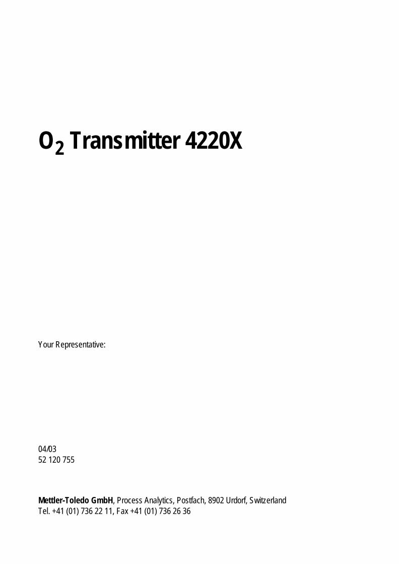
New features for software version 5.0 (April 2003):Units with Option 467 (HART® communication) now also support productcalibration via HART® interface. The O2 Transmitter 4220X supports the new Mettler Toledo InPro6800and InPro6900 sensors.
Typical wiring with InPro6800 or InPro6900 sensors
Not connectedgray
blue
transparent Cathode
Polarizationvoltage -675 mV
yellow/green
red
green
white
Shield
Ref.electrode
Anode
NTC
NTC
Sense line
Additional connection for interference suppression,particularly when measuring low values
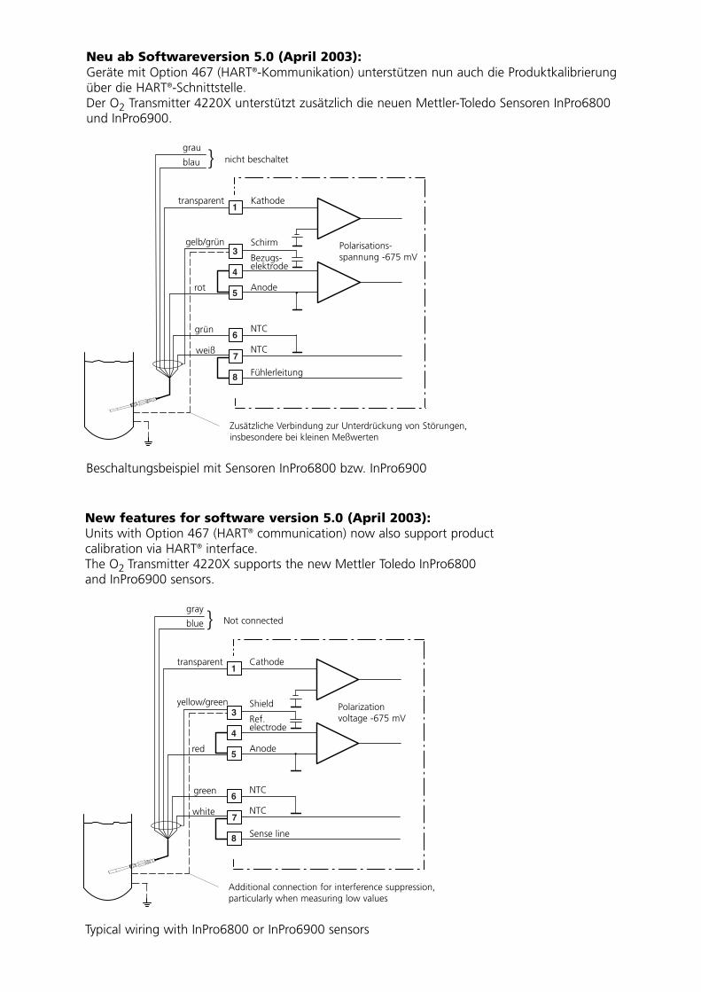
Nouveau à partir de la version 5.0 (Avril 2003):Les appareils avec l'option 467 (communication HART®) supportent également le calibrage duproduit via l'interface HART®. Les nouveaux capteurs Mettler Toledo InPro6800 et InPro6900 sont disponibles pour lesappareils Transmetteur O2 4220X.
Exemple de câblage avec les capteurs InPro6800 ou InPro6900
Sans connexionsgris
bleu
transparent Cathode
Tension de polarisation -675 mV
jaune/vert
rouge
vert
blanc
Blindage
Electrodede réf.
Anode
NTC
NTC
Câble sonde
Raccordement supplémentaire pour la suppression de parasites,en particulier pour les petites valeurs mesurées
Contents
Package contents . . . . . . . . . . . . . . . . . . . . . . . . . . . . . . . . . . . . . . . . . . . . . . . . . . . . . .VII
Information on this instruction manual . . . . . . . . . . . . . . . . . . . . . . . . . . . . . . . . . . . . .VII
Warnings and notes . . . . . . . . . . . . . . . . . . . . . . . . . . . . . . . . . . . . . . . . . . . . . . . . .VII
Typical representations . . . . . . . . . . . . . . . . . . . . . . . . . . . . . . . . . . . . . . . . . . . . . . .VII
Safety information . . . . . . . . . . . . . . . . . . . . . . . . . . . . . . . . . . . . . . . . . . . . . . . . . . . . . VIII
Proper use . . . . . . . . . . . . . . . . . . . . . . . . . . . . . . . . . . . . . . . . . . . . . . . . . . . . . . . . .X
Declaration of conformity . . . . . . . . . . . . . . . . . . . . . . . . . . . . . . . . . . . . . . . . . . . . . . XI
EC-Type-Examination Certificate. . . . . . . . . . . . . . . . . . . . . . . . . . . . . . . . . . . . . . . XII
1 Assembly, installation, and maintenance . . . . . . . . . . . . . . . . . . . . . . . . . . . . . . 1-1
Assembly . . . . . . . . . . . . . . . . . . . . . . . . . . . . . . . . . . . . . . . . . . . . . . . . . . . . . . . . 1-1
Installation and commissioning . . . . . . . . . . . . . . . . . . . . . . . . . . . . . . . . . . . . . . . . 1-5
Notes concerning performance . . . . . . . . . . . . . . . . . . . . . . . . . . . . . . . . . . . . . . . . 1-6
Maintenance and cleaning . . . . . . . . . . . . . . . . . . . . . . . . . . . . . . . . . . . . . . . . . . . 1-6
2 Capabilities of O2 Transmitter 4220X . . . . . . . . . . . . . . . . . . . . . . . . . . . . . . . . . 2-1
Overview of O2 Transmitter 4220X . . . . . . . . . . . . . . . . . . . . . . . . . . . . . . . . . . . . 2-1
Terminal assignments . . . . . . . . . . . . . . . . . . . . . . . . . . . . . . . . . . . . . . . . . . . . . . . 2-3
Dissolved oxygen measurement . . . . . . . . . . . . . . . . . . . . . . . . . . . . . . . . . . . . . . . 2-4
Temperature detection . . . . . . . . . . . . . . . . . . . . . . . . . . . . . . . . . . . . . . . . . . . . . . 2-5
Passive output 2 . . . . . . . . . . . . . . . . . . . . . . . . . . . . . . . . . . . . . . . . . . . . . . . . . . . 2-6
Typical wiring . . . . . . . . . . . . . . . . . . . . . . . . . . . . . . . . . . . . . . . . . . . . . . . . . . . . . 2-7
3 Operating O2 Transmitter 4220X . . . . . . . . . . . . . . . . . . . . . . . . . . . . . . . . . . . . 3-1
User interface . . . . . . . . . . . . . . . . . . . . . . . . . . . . . . . . . . . . . . . . . . . . . . . . . . . . . 3-1
Measuring mode . . . . . . . . . . . . . . . . . . . . . . . . . . . . . . . . . . . . . . . . . . . . . . . . . . . 3-2
Measurement recorder . . . . . . . . . . . . . . . . . . . . . . . . . . . . . . . . . . . . . . . . . . . . . . 3-4
Menu structure . . . . . . . . . . . . . . . . . . . . . . . . . . . . . . . . . . . . . . . . . . . . . . . . . . . . 3-5
Menu operation . . . . . . . . . . . . . . . . . . . . . . . . . . . . . . . . . . . . . . . . . . . . . . . . . . . . 3-6
Contents III
O2 Transmitter 4220X
4 Parameter setting . . . . . . . . . . . . . . . . . . . . . . . . . . . . . . . . . . . . . . . . . . . . . . . . . 4-1
Language selection . . . . . . . . . . . . . . . . . . . . . . . . . . . . . . . . . . . . . . . . . . . . . . . . . 4-1
The three levels of parameter setting . . . . . . . . . . . . . . . . . . . . . . . . . . . . . . . . . . . 4-1
Factory setting . . . . . . . . . . . . . . . . . . . . . . . . . . . . . . . . . . . . . . . . . . . . . . . . . . . . 4-3
Measurement display . . . . . . . . . . . . . . . . . . . . . . . . . . . . . . . . . . . . . . . . . . . . . . . 4-3
Input filter . . . . . . . . . . . . . . . . . . . . . . . . . . . . . . . . . . . . . . . . . . . . . . . . . . . . . . . . 4-4
Pressure correction . . . . . . . . . . . . . . . . . . . . . . . . . . . . . . . . . . . . . . . . . . . . . . . . . 4-4
Salt content . . . . . . . . . . . . . . . . . . . . . . . . . . . . . . . . . . . . . . . . . . . . . . . . . . . . . . . 4-5
Temperature detection . . . . . . . . . . . . . . . . . . . . . . . . . . . . . . . . . . . . . . . . . . . . . . 4-6
Sensor data . . . . . . . . . . . . . . . . . . . . . . . . . . . . . . . . . . . . . . . . . . . . . . . . . . . . . . . 4-7
Output 1 . . . . . . . . . . . . . . . . . . . . . . . . . . . . . . . . . . . . . . . . . . . . . . . . . . . . . . . . . 4-8
Output 2 . . . . . . . . . . . . . . . . . . . . . . . . . . . . . . . . . . . . . . . . . . . . . . . . . . . . . . . . 4-14
Alarm settings . . . . . . . . . . . . . . . . . . . . . . . . . . . . . . . . . . . . . . . . . . . . . . . . . . . . 4-21
Alarm processing / NAMUR signals . . . . . . . . . . . . . . . . . . . . . . . . . . . . . . . . . . . 4-22
HART® Communication . . . . . . . . . . . . . . . . . . . . . . . . . . . . . . . . . . . . . . . . . . . . 4-23
Setting the clock . . . . . . . . . . . . . . . . . . . . . . . . . . . . . . . . . . . . . . . . . . . . . . . . . . 4-25
Point of measurement/note . . . . . . . . . . . . . . . . . . . . . . . . . . . . . . . . . . . . . . . . . . 4-25
Device diagnostics . . . . . . . . . . . . . . . . . . . . . . . . . . . . . . . . . . . . . . . . . . . . . . . . 4-25
Measurement recorder . . . . . . . . . . . . . . . . . . . . . . . . . . . . . . . . . . . . . . . . . . . . . 4-26
Passcode entry . . . . . . . . . . . . . . . . . . . . . . . . . . . . . . . . . . . . . . . . . . . . . . . . . . . 4-27
Release of options . . . . . . . . . . . . . . . . . . . . . . . . . . . . . . . . . . . . . . . . . . . . . . . . 4-29
5 Calibration . . . . . . . . . . . . . . . . . . . . . . . . . . . . . . . . . . . . . . . . . . . . . . . . . . . . . . . 5-1
Why do you have to calibrate? . . . . . . . . . . . . . . . . . . . . . . . . . . . . . . . . . . . . . . . . 5-1
Monitoring functions for calibration . . . . . . . . . . . . . . . . . . . . . . . . . . . . . . . . . . . . . 5-1
Calibration menu . . . . . . . . . . . . . . . . . . . . . . . . . . . . . . . . . . . . . . . . . . . . . . . . . . . 5-2
What does “First Calibration” mean? . . . . . . . . . . . . . . . . . . . . . . . . . . . . . . . . . . . 5-2
One-point or two-point calibration? . . . . . . . . . . . . . . . . . . . . . . . . . . . . . . . . . . . . . 5-3
Automatic calibration in water or air . . . . . . . . . . . . . . . . . . . . . . . . . . . . . . . . . . . . 5-4
Calibration with manual entry of saturation . . . . . . . . . . . . . . . . . . . . . . . . . . . . . . . 5-7
Calibration by data entry . . . . . . . . . . . . . . . . . . . . . . . . . . . . . . . . . . . . . . . . . . . . . 5-8
IV Contents
6 Diagnostics menu . . . . . . . . . . . . . . . . . . . . . . . . . . . . . . . . . . . . . . . . . . . . . . . . . 6-1
Message list . . . . . . . . . . . . . . . . . . . . . . . . . . . . . . . . . . . . . . . . . . . . . . . . . . . . . . 6-1
Cal record . . . . . . . . . . . . . . . . . . . . . . . . . . . . . . . . . . . . . . . . . . . . . . . . . . . . . . . . 6-1
Sensor statistics . . . . . . . . . . . . . . . . . . . . . . . . . . . . . . . . . . . . . . . . . . . . . . . . . . . 6-2
Logbook . . . . . . . . . . . . . . . . . . . . . . . . . . . . . . . . . . . . . . . . . . . . . . . . . . . . . . . . . 6-3
Device description . . . . . . . . . . . . . . . . . . . . . . . . . . . . . . . . . . . . . . . . . . . . . . . . . . 6-3
Device diagnostics . . . . . . . . . . . . . . . . . . . . . . . . . . . . . . . . . . . . . . . . . . . . . . . . . 6-4
Measurement recorder (listing) . . . . . . . . . . . . . . . . . . . . . . . . . . . . . . . . . . . . . . . . 6-5
7 Maintenance menu . . . . . . . . . . . . . . . . . . . . . . . . . . . . . . . . . . . . . . . . . . . . . . . . 7-1
Measurement point maintenance . . . . . . . . . . . . . . . . . . . . . . . . . . . . . . . . . . . . . . 7-1
Sensor monitor . . . . . . . . . . . . . . . . . . . . . . . . . . . . . . . . . . . . . . . . . . . . . . . . . . . . 7-2
Current source function . . . . . . . . . . . . . . . . . . . . . . . . . . . . . . . . . . . . . . . . . . . . . . 7-2
Temperature probe adjustment . . . . . . . . . . . . . . . . . . . . . . . . . . . . . . . . . . . . . . . . 7-3
Manual entry of controller output . . . . . . . . . . . . . . . . . . . . . . . . . . . . . . . . . . . . . . 7-3
Reset Sensocheck® . . . . . . . . . . . . . . . . . . . . . . . . . . . . . . . . . . . . . . . . .7-4
8 Error messages . . . . . . . . . . . . . . . . . . . . . . . . . . . . . . . . . . . . . . . . . . . . . . . . . . . 8-1
9 Product line and accessories . . . . . . . . . . . . . . . . . . . . . . . . . . . . . . . . . . . . . . . 9-1
10 Sensors . . . . . . . . . . . . . . . . . . . . . . . . . . . . . . . . . . . . . . . . . . . . . . . . . . . . . . . . 10-1
11 Specifications . . . . . . . . . . . . . . . . . . . . . . . . . . . . . . . . . . . . . . . . . . . . . . . . . . . 11-1
12 Oxygen solubility table . . . . . . . . . . . . . . . . . . . . . . . . . . . . . . . . . . . . . . . . . . . . 12-1
13 Glossary . . . . . . . . . . . . . . . . . . . . . . . . . . . . . . . . . . . . . . . . . . . . . . . . . . . . . . . . 13-1
14 Index . . . . . . . . . . . . . . . . . . . . . . . . . . . . . . . . . . . . . . . . . . . . . . . . . . . . . . . . . . . 14-1
Contents V

O2 Transmitter 4220X
VI Contents

Package contents
The package should contain:
• O2 Transmitter 4220X
• This instruction manual
• Any accessories ordered with the Transmitter (For available accessories, see Chap. 9)
Information on this instruction manual
Warnings and notes
Warning
Warning means that ignoring the given instruc-tions may lead to a malfunction of or damage to the instrument and to property damage or per-sonal injuries.
Note
Notes provide important information that should be followed when using the instrument.
Typical representations
The keys of the O2 Transmitter 4220X are shown like this in the text:
, , , ,
, , , ,
Menus shown in the instruction manual may differ somewhat from the display of your Transmitter. This depends on which options your Transmitter is equipped with.
If the behavior of your Transmitter deviates from the description in this manual, check whether the man-ual corresponds to the software version of your Transmitter: see Pg 6-3, Device Description.
Information VII
O2 Transmitter 4220X
Safety information
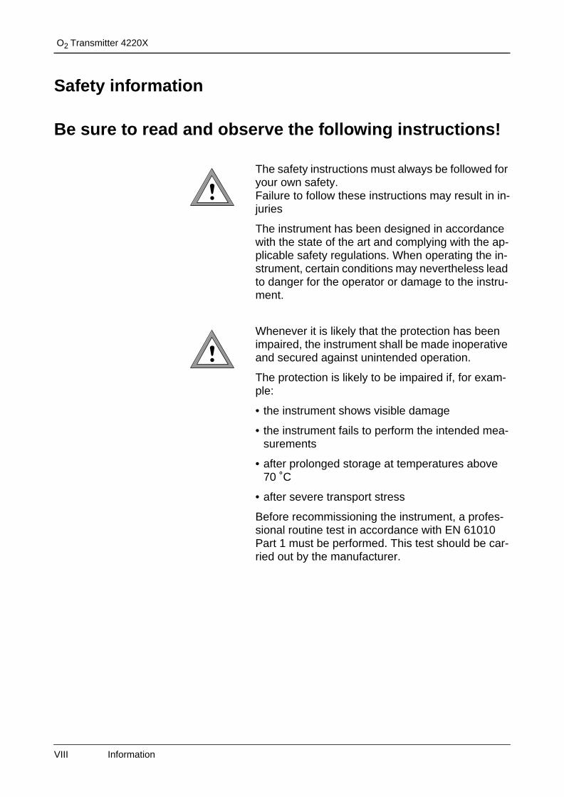
Be sure to read and observe the following instructions!
The safety instructions must always be followed for your own safety.Failure to follow these instructions may result in in-juries
The instrument has been designed in accordance with the state of the art and complying with the ap-plicable safety regulations. When operating the in-strument, certain conditions may nevertheless lead to danger for the operator or damage to the instru-ment.
Whenever it is likely that the protection has been impaired, the instrument shall be made inoperative and secured against unintended operation.
The protection is likely to be impaired if, for exam-ple:
• the instrument shows visible damage
• the instrument fails to perform the intended mea-surements
• after prolonged storage at temperatures above 70 ˚C
• after severe transport stress
Before recommissioning the instrument, a profes-sional routine test in accordance with EN 61010 Part 1 must be performed. This test should be car-ried out by the manufacturer.
VIII Information
The O2 Transmitter 4220X is approved for opera-tion in hazardous locations. It has been developed and manufactured in compliance with the applica-ble European guidelines and standards. The Declaration of Conformity confirms the compli-ance with the applicable European guidelines and standards.
The stipulations of EN 60 079-14:1996 and the fol-lowing must be observed when installing the instru-ment in a hazardous location. The O2 Transmitter 4220X may only be connected to certified intrinsi-cally safe circuits. The electrical data are listed in the EC-Type-Examination Certificate (see Pg XII).
Before commissioning it must be proved that the in-trinsic safety is maintained when connecting the in-strument to other equipment, such as supply units including cables and lines.
When commissioning, a complete configuration must be carried out.
Manipulations of the instrument other than de-scribed in this manual are not permitted.
Assembly/dismantling, installation, operation and maintenance may only be carried out by qualified personnel as defined by the automation industry in compliance with the applicable regulations and this instruction manual. Be sure to observe the speci-fied ambient conditions and installation instructions.
Information IX
O2 Transmitter 4220X
Proper use
The O2 Transmitter 4220X is a 2-wire transmitter. The Transmitter is supplied with power from the 4 to 20 mA loop current, which also transmits the measured variable.
The O2 Transmitter 4220X is used for continuous measurement of oxygen saturation, concentration and partial pressure, as well as for temperature measurement in liquids. The instrument is designed for industrial use. The enclosure is protected to IP 65 and allows direct wall mounting on the site.
The instrument shall not be used in a manner not specified by this manual. Any applications not spec-ified in this manual are inadmissible.
X Information
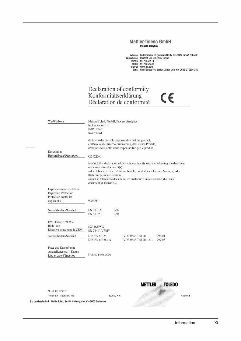
Declaration of conformity
Information XI
O2 Transmitter 4220X
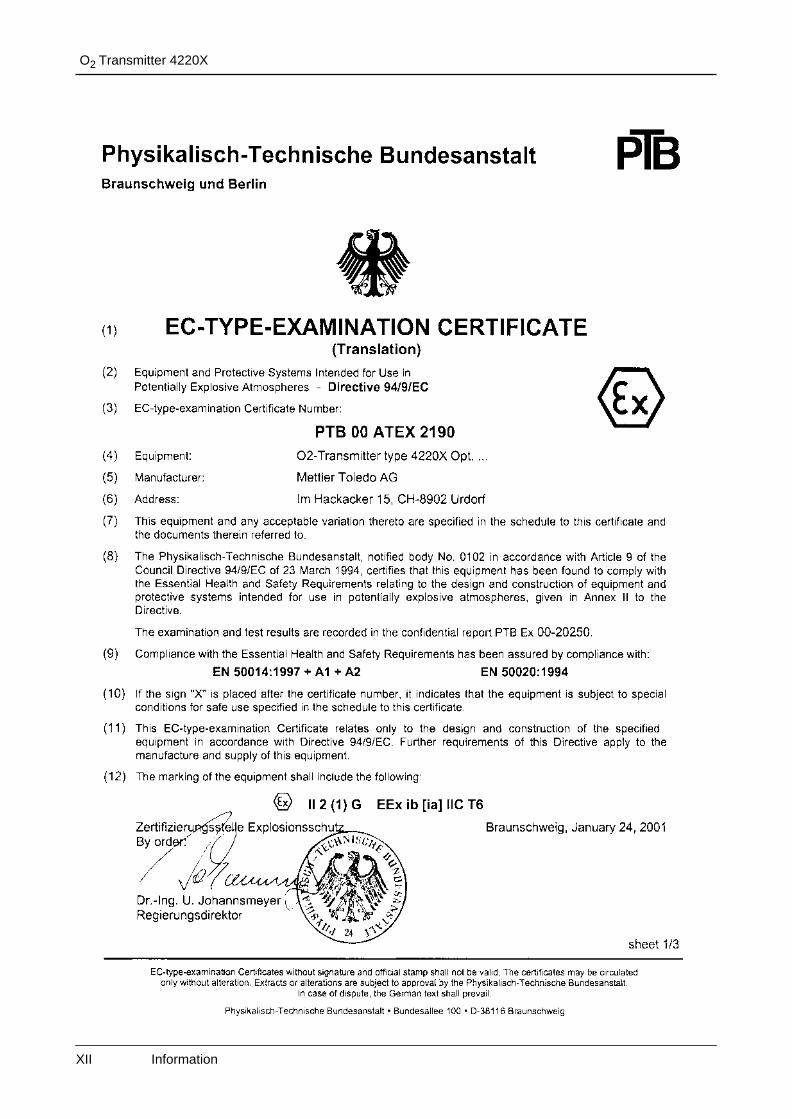
EC-Type-Examination Certificate
XII Information
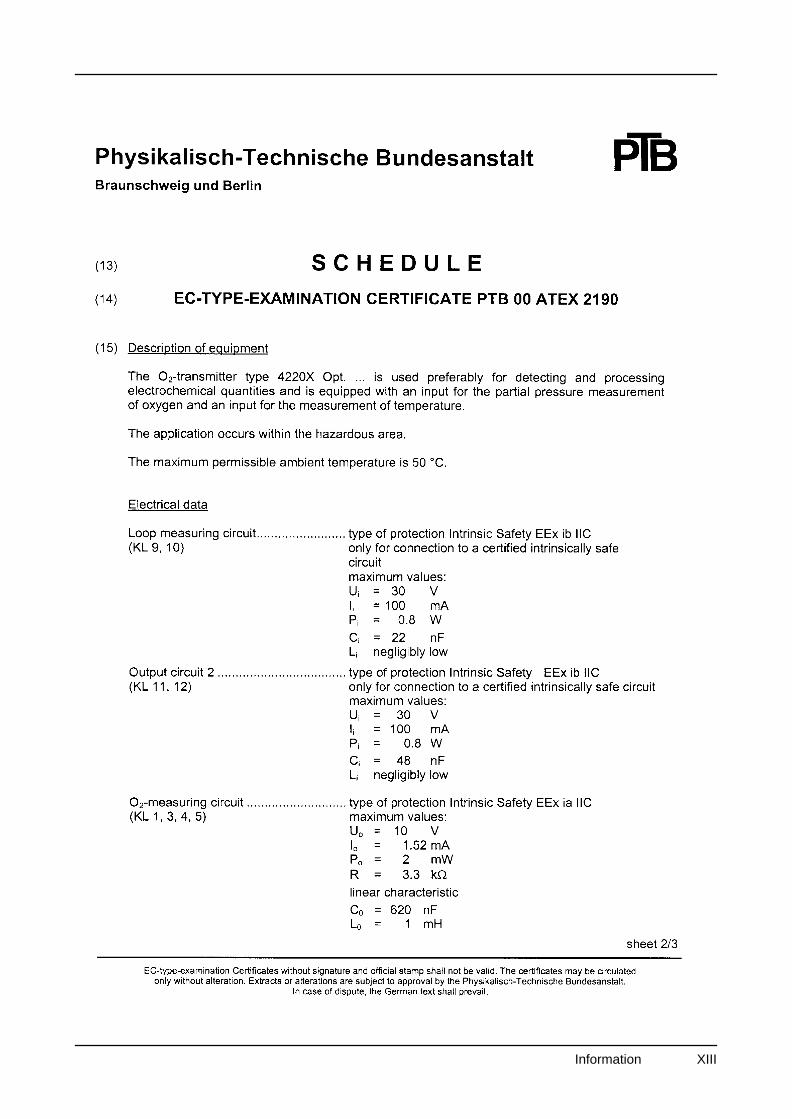
Information XIII
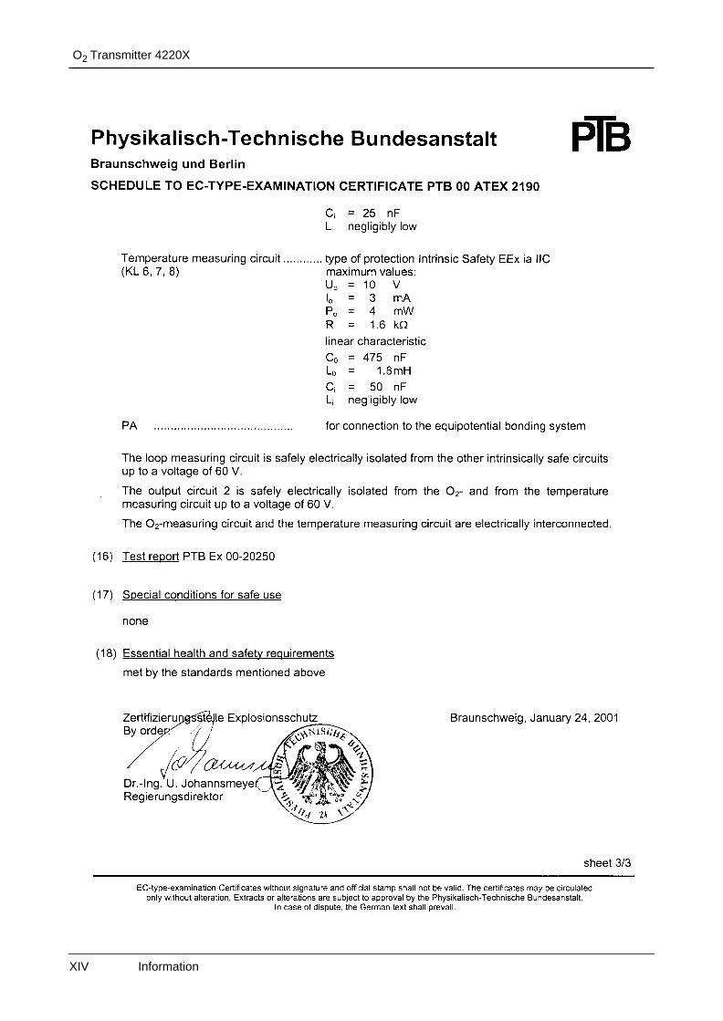
O2 Transmitter 4220X
XIV Information
1 Assembly, installation, and maintenance
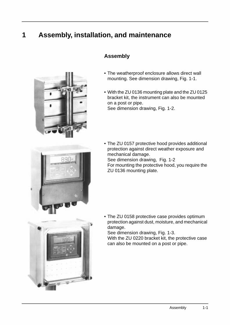
Assembly
• The weatherproof enclosure allows direct wall mounting. See dimension drawing, Fig. 1-1.
• With the ZU 0136 mounting plate and the ZU 0125 bracket kit, the instrument can also be mounted on a post or pipe.See dimension drawing, Fig. 1-2.
• The ZU 0157 protective hood provides additional protection against direct weather exposure and mechanical damage.See dimension drawing, Fig. 1-2For mounting the protective hood, you require the ZU 0136 mounting plate.
• The ZU 0158 protective case provides optimum protection against dust, moisture, and mechanical damage.See dimension drawing, Fig. 1-3.With the ZU 0220 bracket kit, the protective case can also be mounted on a post or pipe.
Assembly 1-1
O2 Transmitter 4220X
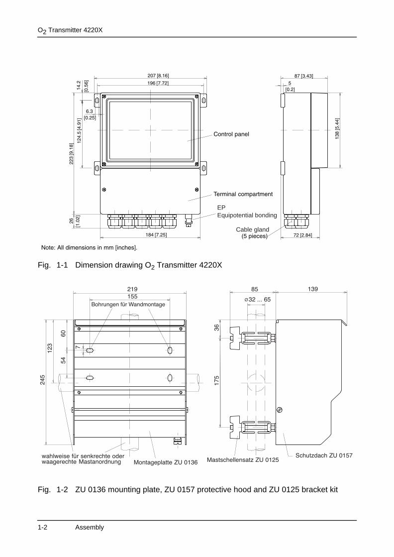
Fig. 1-1 Dimension drawing O2 Transmitter 4220X
Fig. 1-2 ZU 0136 mounting plate, ZU 0157 protective hood and ZU 0125 bracket kit
Cable gland
EPEquipotential bonding
1-2 Assembly
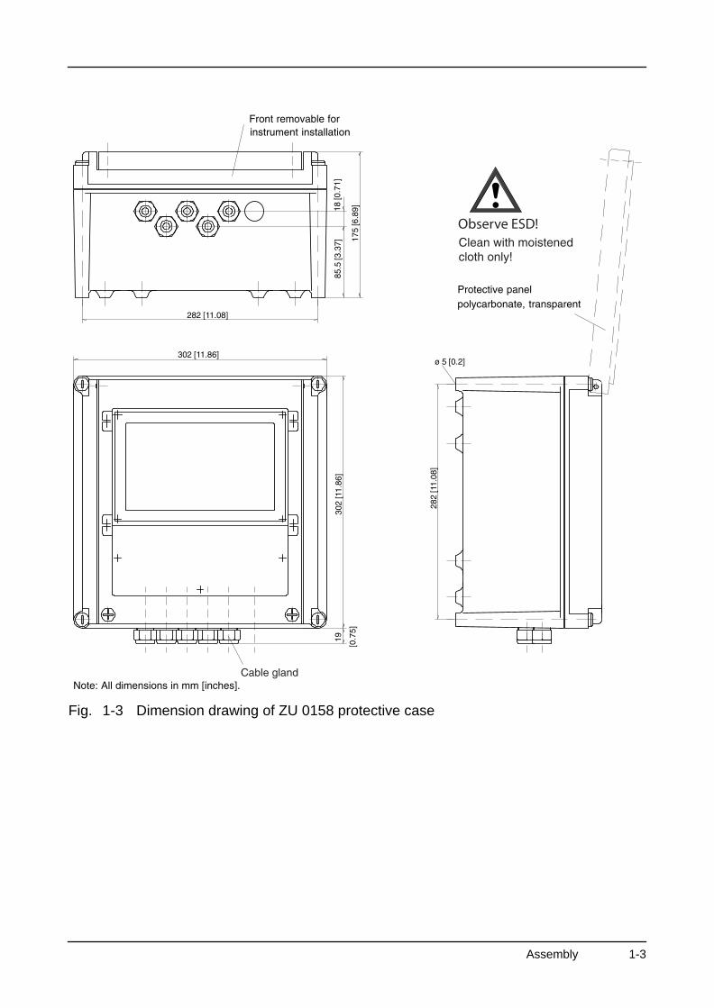
Fig. 1-3 Dimension drawing of ZU 0158 protective case
Assembly 1-3
O2 Transmitter 4220X
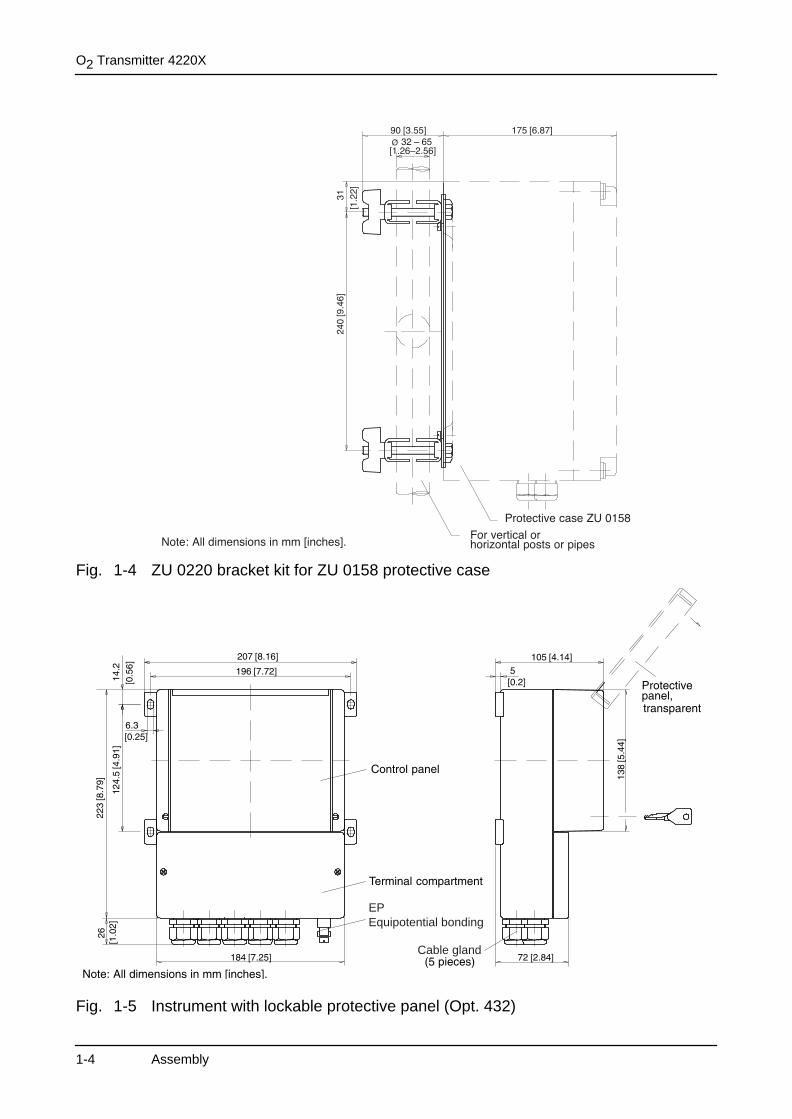
Fig. 1-4 ZU 0220 bracket kit for ZU 0158 protective case
Fig. 1-5 Instrument with lockable protective panel (Opt. 432)
Cable gland
EPEquipotential bonding
1-4 Assembly

Installation and commissioning
• Installation and commissioning of the O2 Trans-mitter 4220X may only be carried out by trained experts in accordance with this instruction manual and as per applicable local and national codes. Be sure to observe the technical specifications and input ratings.
• All parameters must be set by a system adminis-trator prior to commissioning.
• Be sure to observe the safety precautions on Pg VIII and the following!
Before connecting the O2 Transmitter 4220X to a supply unit, make sure that it cannot output more than 30 V DC, 100 mA and 0.8 W.
To connect the O2 Transmitter 4220X, open the cover of the terminal compartment (lower part of the instrument) by removing the two screws. The termi-nals are suitable for single wires and flexible leads up to 2.5 mm2 (AWG 14). On the right-hand side next to the terminals there are two contact holes for connecting a HART® hand-held terminal.
As delivered, all terminals are open to allow easy in-sertion of the connecting wires. If the terminals are only half open, it may occur that the wire is pushed below the contacting element and does not make contact when the terminal is closed.Connection examples are shown on Pg 2-4 and the following.
The outer EP terminal must be connected with equipotential bonding to divert electrostatic charges to the front panel overlay.
Assembly 1-5
O2 Transmitter 4220X
Notes concerning performance
At ambient temperatures below 0 °C the readability of the LC display may be reduced. This does not im-pair the instrument functions.
The real-time clock, logbook, cal record, and sen-sor statistics are battery-backed for approx. 1 year. After longer power outages these data can be lost. The instrument then displays the message “Warn Time/Date”, and the date is reset to 01/01/1990. Time and date must be reentered.
Maintenance and cleaning
The O2 Transmitter 4220X contains no user repair-able components.
To remove dust, dirt and spots, the external surfac-es of the meter may be wiped with a damp, lint-free cloth. A mild household cleaner may also be used if necessary.
When operating the instrument in a hazardous area, pay attention to electrostatic discharge!
Only clean the instrument with a moistened cloth!
Also the ZU 0158 protective case and the lockable protective panel (Opt. 432) may only be cleaned with a moistened cloth!
1-6 Assembly
2 Capabilities of O2 Transmitter 4220X
Overview of O2 Transmitter 4220X
Commissioning of the O2 Transmitter 4220X may only be carried out by trained experts in accordance with this instruction manual. Be sure to observe the technical specifications and input ratings during in-stallation.
All parameters must be set by a system administra-tor prior to commissioning.
The O2 Transmitter 4220X is approved for opera-tion in hazardous locations.
Membrane-covered oxygen sensors supply a cur-rent proportional to the oxygen partial pressure. With Henry’s Law, the oxygen concentration can be calculated from the oxygen partial pressure via a solubility coefficient.In the O2 Transmitter 4220X the solubility coeffi-cient is stored for the respective temperature from -5 °C to +60 °C as a table in accordance with EN 25814 1992. In addition, the influence of the salt content (salinity) of the medium on the solubility can be taken into account. The salt content is either specified directly as the salinity or chlorine content, or the conductivity and temperature of the medium are entered. The salinity is calculated from the con-ductivity and temperature using the International Oceanographic Tables, Unesco / National Institute of Oceanography of Great Britain Volume 2, Worm-ley/ Godalming/Surrey.
Capabilities, Connection 2-1
O2 Transmitter 4220X
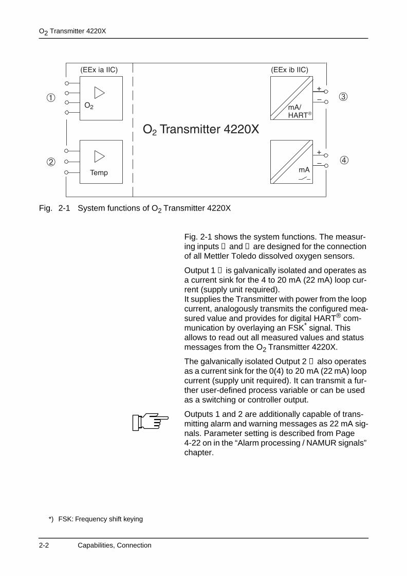
Fig. 2-1 System functions of O2 Transmitter 4220X
Fig. 2-1 shows the system functions. The measur-ing inputs ➀ and ➁ are designed for the connection of all Mettler Toledo dissolved oxygen sensors.
Output 1 ➂ is galvanically isolated and operates as a current sink for the 4 to 20 mA (22 mA) loop cur-rent (supply unit required).It supplies the Transmitter with power from the loop current, analogously transmits the configured mea-sured value and provides for digital HART® com-munication by overlaying an FSK* signal. This allows to read out all measured values and status messages from the O2 Transmitter 4220X.
The galvanically isolated Output 2 ➃ also operates as a current sink for the 0(4) to 20 mA (22 mA) loop current (supply unit required). It can transmit a fur-ther user-defined process variable or can be used as a switching or controller output.
Outputs 1 and 2 are additionally capable of trans-mitting alarm and warning messages as 22 mA sig-nals. Parameter setting is described from Page 4-22 on in the “Alarm processing / NAMUR signals” chapter.
®
*) FSK: Frequency shift keying
2-2 Capabilities, Connection
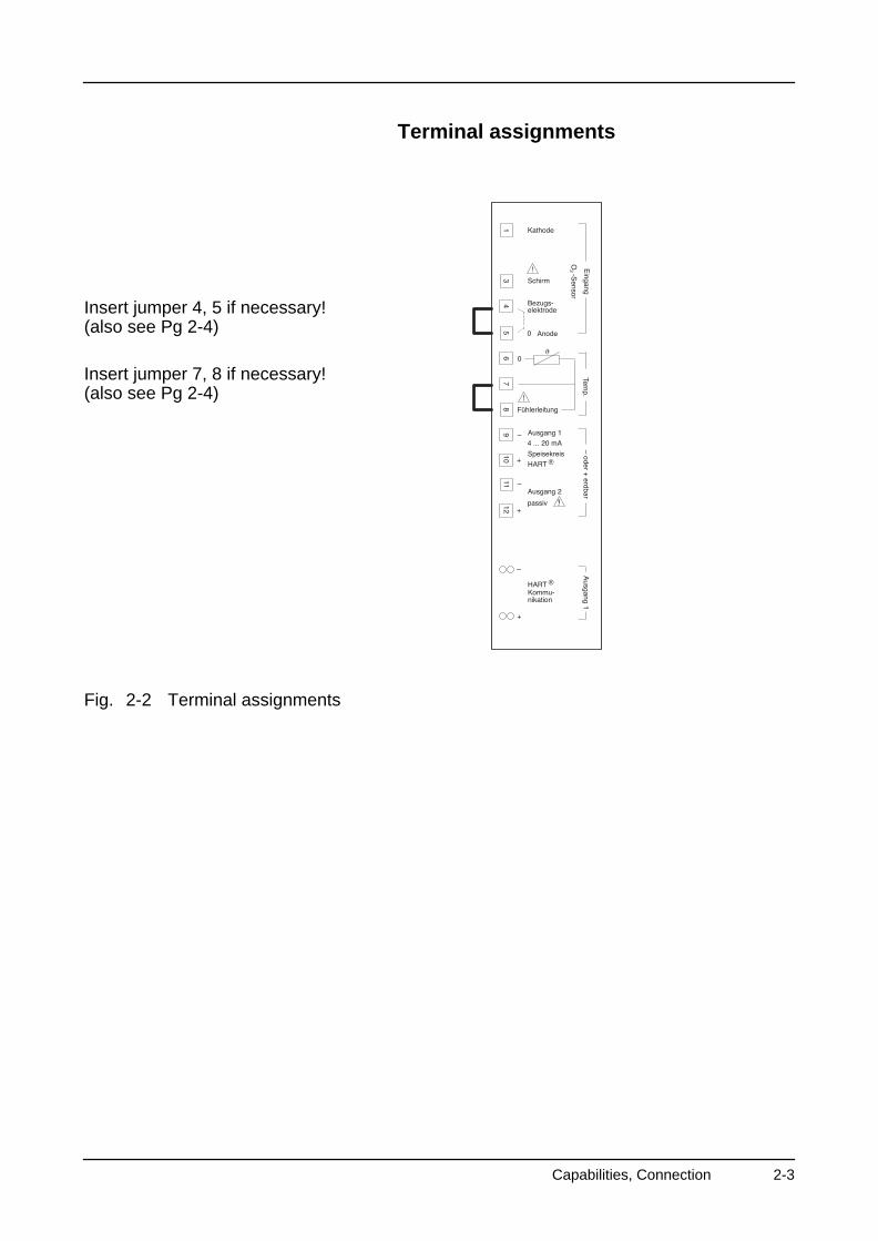
Terminal assignments
Insert jumper 4, 5 if necessary!(also see Pg 2-4)
Insert jumper 7, 8 if necessary!(also see Pg 2-4)
Fig. 2-2 Terminal assignments
Capabilities, Connection 2-3
O2 Transmitter 4220X
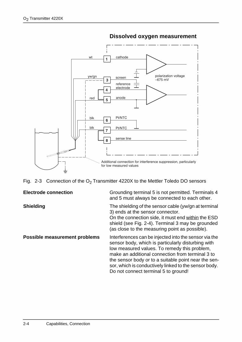
Dissolved oxygen measurement
Fig. 2-3 Connection of the O2 Transmitter 4220X to the Mettler Toledo DO sensors
Electrode connection Grounding terminal 5 is not permitted. Terminals 4 and 5 must always be connected to each other.
Shielding The shielding of the sensor cable (yw/gn at terminal 3) ends at the sensor connector. On the connection side, it must end within the ESD shield (see Fig. 2-4). Terminal 3 may be grounded (as close to the measuring point as possible).
Possible measurement problems Interferences can be injected into the sensor via the sensor body, which is particularly disturbing with low measured values. To remedy this problem, make an additional connection from terminal 3 to the sensor body or to a suitable point near the sen-sor, which is conductively linked to the sensor body. Do not connect terminal 5 to ground!
2-4 Capabilities, Connection
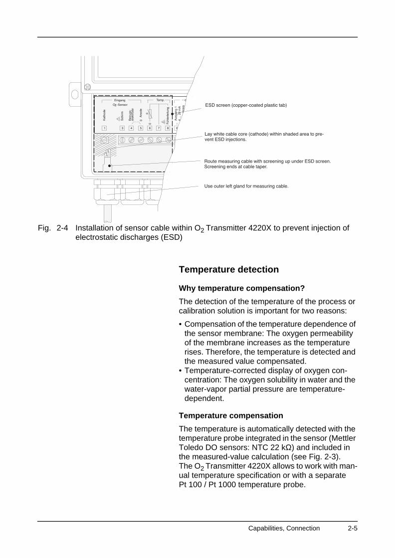
Fig. 2-4 Installation of sensor cable within O2 Transmitter 4220X to prevent injection of electrostatic discharges (ESD)
Temperature detection
Why temperature compensation?
The detection of the temperature of the process or calibration solution is important for two reasons:
• Compensation of the temperature dependence of the sensor membrane: The oxygen permeability of the membrane increases as the temperature rises. Therefore, the temperature is detected and the measured value compensated.
• Temperature-corrected display of oxygen con-centration: The oxygen solubility in water and the water-vapor partial pressure are temperature-dependent.
Temperature compensation
The temperature is automatically detected with the temperature probe integrated in the sensor (Mettler Toledo DO sensors: NTC 22 kΩ) and included in the measured-value calculation (see Fig. 2-3).The O2 Transmitter 4220X allows to work with man-ual temperature specification or with a separate Pt 100 / Pt 1000 temperature probe.
Capabilities, Connection 2-5
O2 Transmitter 4220X
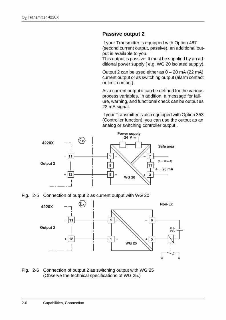
Passive output 2
If your Transmitter is equipped with Option 487 (second current output, passive), an additional out-put is available to you.This output is passive. It must be supplied by an ad-ditional power supply ( e.g. WG 20 isolated supply).
Output 2 can be used either as 0 – 20 mA (22 mA) current output or as switching output (alarm contact or limit contact).
As a current output it can be defined for the various process variables. In addition, a message for fail-ure, warning, and functional check can be output as 22 mA signal.
If your Transmitter is also equipped with Option 353 (Controller function), you can use the output as an analog or switching controller output .
Fig. 2-5 Connection of output 2 as current output with WG 20
Fig. 2-6 Connection of output 2 as switching output with WG 25(Observe the technical specifications of WG 25.)
2-6 Capabilities, Connection

Typical wiring
Fig. 2-7 Dissolved oxygen measurement with recorder evaluation, control and connection to a process control system
Connect EP terminal to equipotential bonding!See Fig. 1-3 and Fig. 1-5 on Pg 1-3 and the follow-ing.
This page has been left empty for technical reasons.
EPEquipotential bonding
Keypad
Capabilities, Connection 2-7

O2 Transmitter 4220X
2-8 Capabilities, Connection

3 Operating O2 Transmitter 4220X
The O2 Transmitter 4220X may only be commis-sioned by trained experts in accordance with this in-struction manual and as per applicable local and national codes.
All parameters must be set by a system administra-tor prior to commissioning.
User interface
Fig. 3-1 User interface of the O2 Transmitter 4220X
METTLER TOLEDO
Capabilities, Connection 3-1
O2 Transmitter 4220X
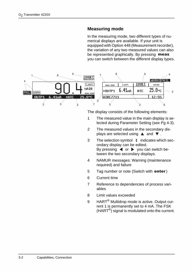
Measuring mode
In the measuring mode, two different types of nu-merical displays are available. If your unit is equipped with Option 448 (Measurement recorder), the variation of any two measured values can also be represented graphically. By pressing you can switch between the different display types.
The display consists of the following elements:
1 The measured value in the main display is se-lected during Parameter Setting (see Pg 4-3).
2 The measured values in the secondary dis-plays are selected using and .
3 The selection symbol indicates which sec-ondary display can be edited.By pressing or you can switch be-tween the two secondary displays.
4 NAMUR messages: Warning (maintenance required) and failure
5 Tag number or note (Switch with )
6 Current time
7 Reference to dependencies of process vari-ables
8 Limit values exceeded
9 HART® Multidrop mode is active. Output cur-rent 1 is permanently set to 4 mA. The FSK (HART®) signal is modulated onto the current.
3-2 Capabilities, Connection

Keypad assignment in measuring mode
switches between the two different types of mea-sured value display. With Option 448 also to the measurement recorder.
activates Calibration, Parameter Setting, Mainte-nance, or Diagnostics.
switches between tag number and note.
select secondary display for changing the process variable.
change process variable in the secondary display.
Refer to Page 4-3 for an overview of the process variables that can be displayed.
Capabilities, Connection 3-3
O2 Transmitter 4220X
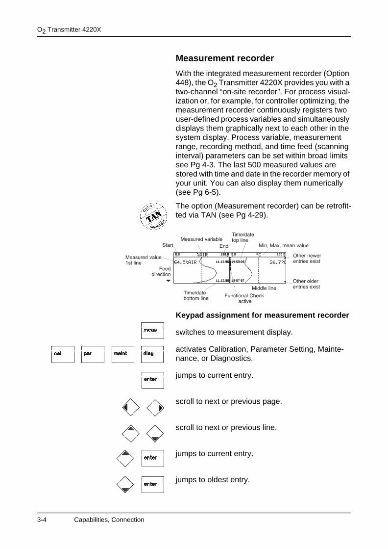
Measurement recorder
With the integrated measurement recorder (Option 448), the O2 Transmitter 4220X provides you with a two-channel “on-site recorder”. For process visual-ization or, for example, for controller optimizing, the measurement recorder continuously registers two user-defined process variables and simultaneously displays them graphically next to each other in the system display. Process variable, measurement range, recording method, and time feed (scanning interval) parameters can be set within broad limits see Pg 4-3. The last 500 measured values are stored with time and date in the recorder memory of your unit. You can also display them numerically (see Pg 6-5).
The option (Measurement recorder) can be retrofit-ted via TAN (see Pg 4-29).
Keypad assignment for measurement recorder
switches to measurement display.
activates Calibration, Parameter Setting, Mainte-nance, or Diagnostics.
jumps to current entry.
scroll to next or previous page.
scroll to next or previous line.
jumps to current entry.
jumps to oldest entry.
3-4 Capabilities, Connection
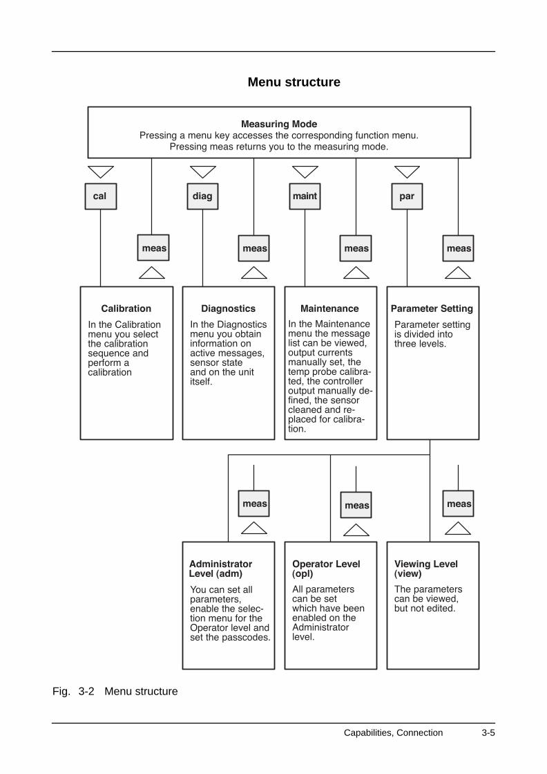
Menu structure
Fig. 3-2 Menu structure
Capabilities, Connection 3-5
O2 Transmitter 4220X
Menu operation
When Calibration, Maintenance, Parameter Setting or Diagnostics are active, the display shows the re-spective menu for operating the functions.
Operator guidance is supported by a 7-line plaintext display with information texts. During operation, the measured value display (4) and the active status messages (3) remain visible.
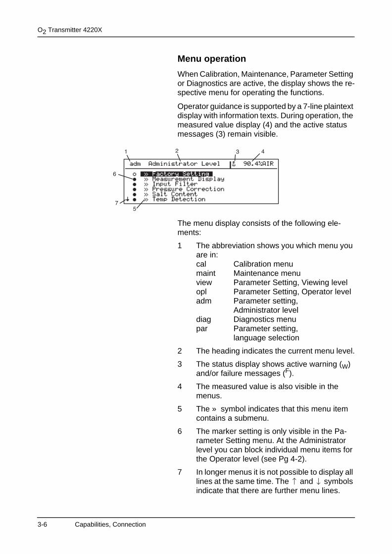
The menu display consists of the following ele-ments:
1 The abbreviation shows you which menu you are in:cal Calibration menumaint Maintenance menuview Parameter Setting, Viewing levelopl Parameter Setting, Operator leveladm Parameter setting,
Administrator leveldiag Diagnostics menupar Parameter setting,
language selection
2 The heading indicates the current menu level.
3 The status display shows active warning (W) and/or failure messages (F).
4 The measured value is also visible in the menus.
5 The » symbol indicates that this menu item contains a submenu.
6 The marker setting is only visible in the Pa-rameter Setting menu. At the Administrator level you can block individual menu items for the Operator level (see Pg 4-2).
7 In longer menus it is not possible to display all lines at the same time. The and symbols indicate that there are further menu lines.
3-6 Capabilities, Connection
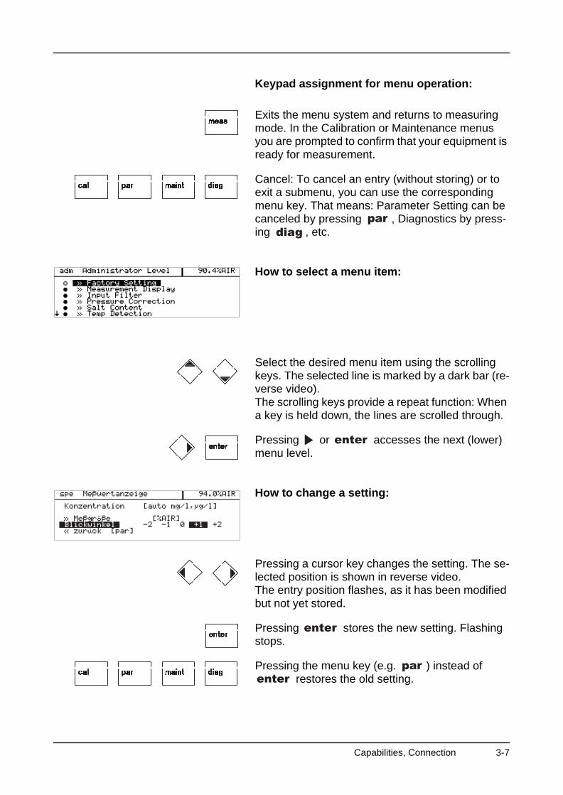
Keypad assignment for menu operation:
Exits the menu system and returns to measuring mode. In the Calibration or Maintenance menus you are prompted to confirm that your equipment is ready for measurement.
Cancel: To cancel an entry (without storing) or to exit a submenu, you can use the corresponding menu key. That means: Parameter Setting can be canceled by pressing , Diagnostics by press-ing , etc.
How to select a menu item:
Select the desired menu item using the scrolling keys. The selected line is marked by a dark bar (re-verse video).The scrolling keys provide a repeat function: When a key is held down, the lines are scrolled through.
Pressing or accesses the next (lower) menu level.
How to change a setting:
Pressing a cursor key changes the setting. The se-lected position is shown in reverse video.The entry position flashes, as it has been modified but not yet stored.
Pressing stores the new setting. Flashing stops.
Pressing the menu key (e.g. ) instead of restores the old setting.
Capabilities, Connection 3-7
O2 Transmitter 4220X
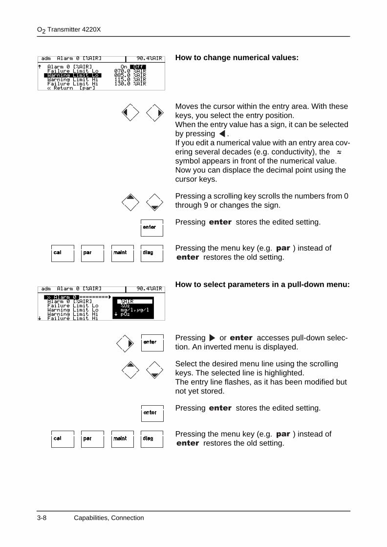
How to change numerical values:
Moves the cursor within the entry area. With these keys, you select the entry position.When the entry value has a sign, it can be selected by pressing .If you edit a numerical value with an entry area cov-ering several decades (e.g. conductivity), the symbol appears in front of the numerical value. Now you can displace the decimal point using the cursor keys.
Pressing a scrolling key scrolls the numbers from 0 through 9 or changes the sign.
Pressing stores the edited setting.
Pressing the menu key (e.g. ) instead of restores the old setting.
How to select parameters in a pull-down menu:
Pressing or accesses pull-down selec-tion. An inverted menu is displayed.
Select the desired menu line using the scrolling keys. The selected line is highlighted. The entry line flashes, as it has been modified but not yet stored.
Pressing stores the edited setting.
Pressing the menu key (e.g. ) instead of restores the old setting.
3-8 Capabilities, Connection
4 Parameter setting
Commissioning of the O2 Transmitter 4220X may only be carried out by trained experts in accordance with this instruction manual.All parameters must be set by a system administra-tor prior to commissioning.
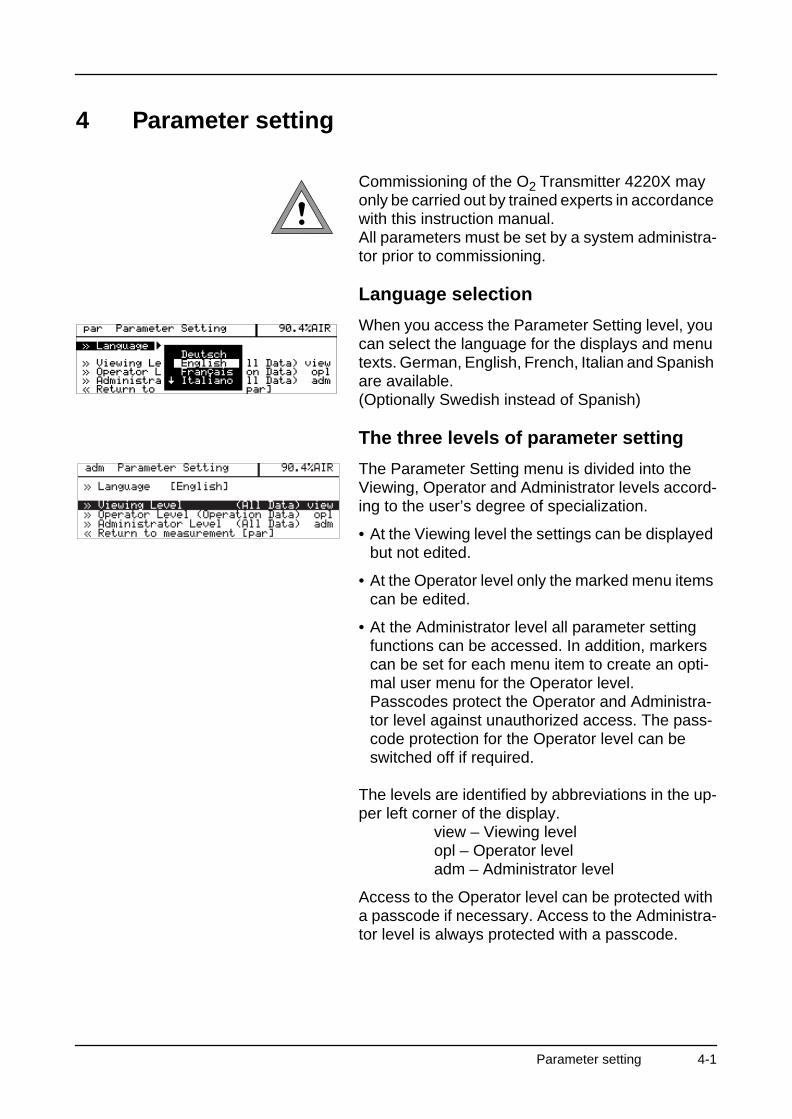
Language selection
When you access the Parameter Setting level, you can select the language for the displays and menu texts. German, English, French, Italian and Spanish are available.(Optionally Swedish instead of Spanish)
The three levels of parameter setting
The Parameter Setting menu is divided into the Viewing, Operator and Administrator levels accord-ing to the user’s degree of specialization.
• At the Viewing level the settings can be displayed but not edited.
• At the Operator level only the marked menu items can be edited.
• At the Administrator level all parameter setting functions can be accessed. In addition, markers can be set for each menu item to create an opti-mal user menu for the Operator level.Passcodes protect the Operator and Administra-tor level against unauthorized access. The pass-code protection for the Operator level can be switched off if required.
The levels are identified by abbreviations in the up-per left corner of the display.
view – Viewing levelopl – Operator leveladm – Administrator level
Access to the Operator level can be protected with a passcode if necessary. Access to the Administra-tor level is always protected with a passcode.
Parameter setting 4-1
O2 Transmitter 4220X
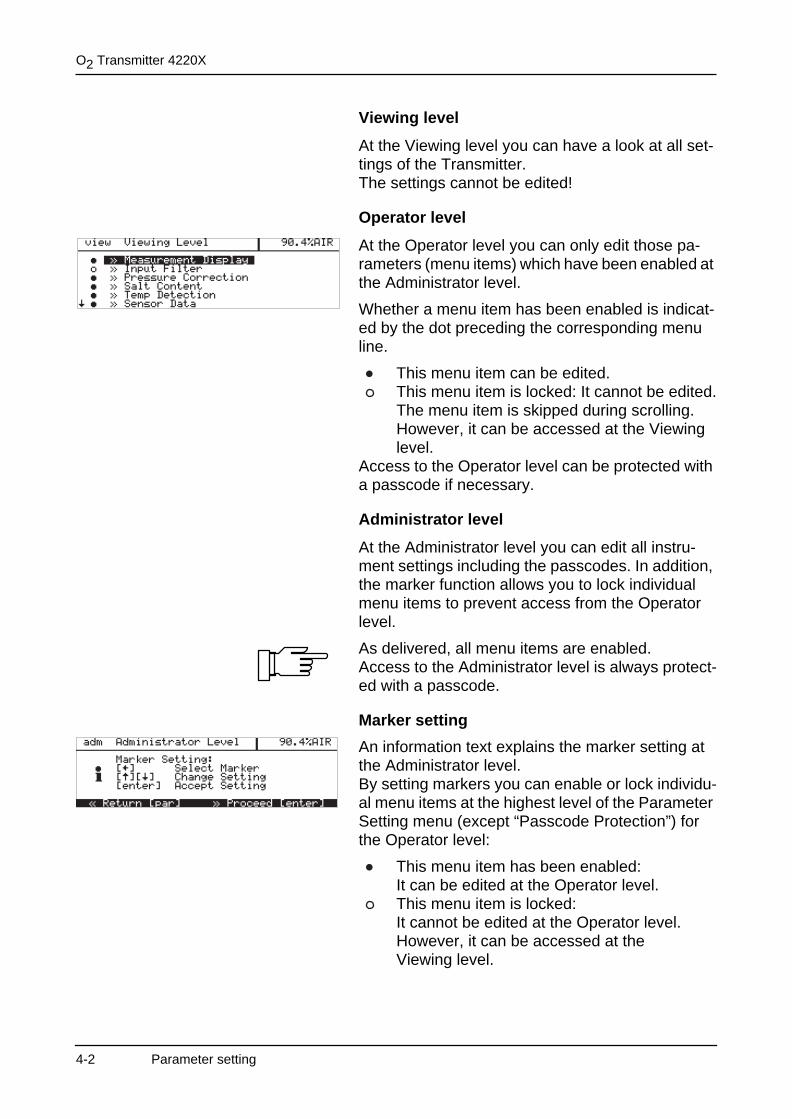
Viewing level
At the Viewing level you can have a look at all set-tings of the Transmitter.The settings cannot be edited!
Operator level
At the Operator level you can only edit those pa-rameters (menu items) which have been enabled at the Administrator level.
Whether a menu item has been enabled is indicat-ed by the dot preceding the corresponding menu line.
This menu item can be edited.This menu item is locked: It cannot be edited.The menu item is skipped during scrolling.However, it can be accessed at the Viewinglevel.
Access to the Operator level can be protected with a passcode if necessary.
Administrator level
At the Administrator level you can edit all instru-ment settings including the passcodes. In addition, the marker function allows you to lock individual menu items to prevent access from the Operator level.
As delivered, all menu items are enabled.Access to the Administrator level is always protect-ed with a passcode.
Marker setting
An information text explains the marker setting at the Administrator level.By setting markers you can enable or lock individu-al menu items at the highest level of the Parameter Setting menu (except “Passcode Protection”) for the Operator level:
This menu item has been enabled: It can be edited at the Operator level.This menu item is locked: It cannot be edited at the Operator level. However, it can be accessed at the Viewing level.
4-2 Parameter setting
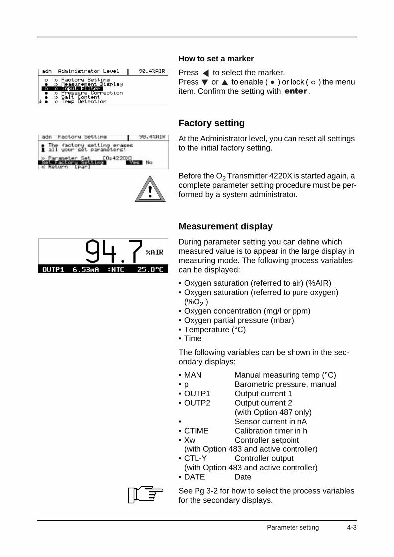
How to set a marker
Press to select the marker. Press or to enable ( ) or lock ( ) the menu item. Confirm the setting with .
Factory setting
At the Administrator level, you can reset all settings to the initial factory setting.
Before the O2 Transmitter 4220X is started again, a complete parameter setting procedure must be per-formed by a system administrator.
Measurement display
During parameter setting you can define which measured value is to appear in the large display in measuring mode. The following process variables can be displayed:
• Oxygen saturation (referred to air) (%AIR)• Oxygen saturation (referred to pure oxygen)
(%O2 )• Oxygen concentration (mg/l or ppm)• Oxygen partial pressure (mbar)• Temperature (°C)• Time
The following variables can be shown in the sec-ondary displays:
• MAN Manual measuring temp (°C) • p Barometric pressure, manual • OUTP1 Output current 1 • OUTP2 Output current 2
(with Option 487 only)• Sensor current in nA • CTIME Calibration timer in h • Xw Controller setpoint
(with Option 483 and active controller) • CTL-Y Controller output
(with Option 483 and active controller) • DATE Date
See Pg 3-2 for how to select the process variables for the secondary displays.
Parameter setting 4-3
O2 Transmitter 4220X
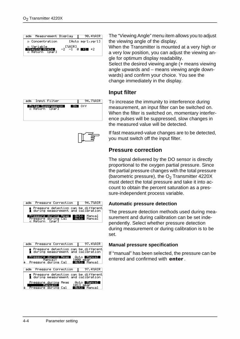
The “Viewing Angle” menu item allows you to adjust the viewing angle of the display. When the Transmitter is mounted at a very high or a very low position, you can adjust the viewing an-gle for optimum display readability. Select the desired viewing angle (+ means viewing angle upwards and – means viewing angle down-wards) and confirm your choice. You see the change immediately in the display.
Input filter
To increase the immunity to interference during measurement, an input filter can be switched on.When the filter is switched on, momentary interfer-ence pulses will be suppressed, slow changes in the measured value will be detected.
If fast measured-value changes are to be detected, you must switch off the input filter.
Pressure correction
The signal delivered by the DO sensor is directly proportional to the oxygen partial pressure. Since the partial pressure changes with the total pressure (barometric pressure), the O2 Transmitter 4220X must detect the total pressure and take it into ac-count to obtain the percent saturation as a pres-sure-independent process variable.
Automatic pressure detection
The pressure detection methods used during mea-surement and during calibration can be set inde-pendently. Select whether pressure detection during measurement or during calibration is to be set.
Manual pressure specification
If “manual” has been selected, the pressure can be entered and confirmed with .
4-4 Parameter setting
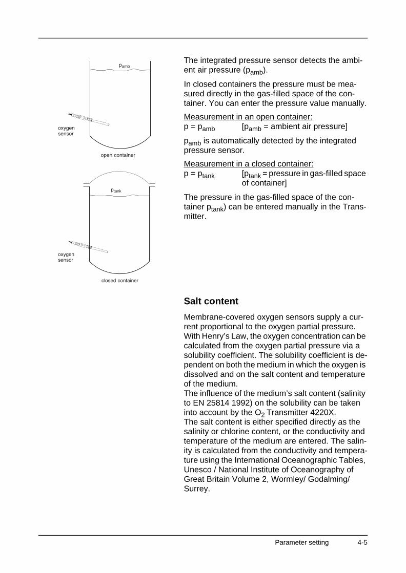
The integrated pressure sensor detects the ambi-ent air pressure (pamb).
In closed containers the pressure must be mea-sured directly in the gas-filled space of the con-tainer. You can enter the pressure value manually.
Measurement in an open container:p = pamb [pamb = ambient air pressure]
pamb is automatically detected by the integrated pressure sensor.
Measurement in a closed container:p = ptank [ptank = pressure in gas-filled space
of container]
The pressure in the gas-filled space of the con-tainer ptank) can be entered manually in the Trans-mitter.
Salt content
Membrane-covered oxygen sensors supply a cur-rent proportional to the oxygen partial pressure. With Henry’s Law, the oxygen concentration can be calculated from the oxygen partial pressure via a solubility coefficient. The solubility coefficient is de-pendent on both the medium in which the oxygen is dissolved and on the salt content and temperature of the medium.The influence of the medium’s salt content (salinity to EN 25814 1992) on the solubility can be taken into account by the O2 Transmitter 4220X.The salt content is either specified directly as the salinity or chlorine content, or the conductivity and temperature of the medium are entered. The salin-ity is calculated from the conductivity and tempera-ture using the International Oceanographic Tables, Unesco / National Institute of Oceanography of Great Britain Volume 2, Wormley/ Godalming/Surrey.
Parameter setting 4-5

O2 Transmitter 4220X
How to set the salt content parameters
Open a Parameter Setting menu and select “Salt Content”.
Select whether you want to enter the salinity di-rectly or specify the chlorine content or a conductiv-ity value (Cond).
Enter the selected value.
If you specify a conductivity value, you can also en-ter the temperature value.
The corresponding salinity value is calculated from the chlorine content or the conductivity value and then used for correcting the oxygen concentration value.
Temperature detection
The temperature is automatically detected with the temperature probe integrated in the sensor (Mettler Toledo DO sensors: NTC 22 kΩ) and included in the measured-value calculation.
Automatic temperature compensation
The Mettler Toledo dissolved oxygen sensors have an integrated NTC 22 kΩ temperature probe.
Select the NTC 22 kΩ probe in the Temp Probe menu.The process temperature is automatically detected with the integrated temperature probe and taken into account for compensation.
Manual temperature compensation
The O2 Transmitter 4220X allows to work with man-ual temperature specification or with a separate Pt 100 / Pt 1000 temperature probe.
4-6 Parameter setting

Sensor data
The sensor data for the Mettler Toledo dissolved oxygen sensors are preset in the O2 Transmitter 4220X.
• Polarization voltageDuring amperometric oxygen measurement the oxygen is cathodically reduced. Therefore, the re-quired polarization voltage is negative. It is -675 mV.
• Temperature probe(Default setting: NTC) The SE 704 and SE 705 sensors are equipped with an NTC 22 kΩ.
• Sensocheck®
(Default setting: Off)The Sensocheck® sensor monitoring function has been optimized for the Mettler Toledo dissolved oxygen sensors. With Sensocheck® switched on, the impedance between the anode and cathode is monitored.Rapid impedance changes, e.g. due to mechani-cal stress on the membrane, trigger the message “Warn Sensocheck”. You can acknowledge (re-set) this message in the Maintenance menu or perform a new calibration (and maintenance, if re-quired) of the DO sensor. Appearance and disap-pearance of this message is recorded in the logbook. Slow impedance changes have no ef-fect.
Sensocheck® has been optimized for automatic temperature compensation. When using manual temperature compensation, Sensocheck® should be switched off to prevent false alarms.
Parameter setting 4-7
O2 Transmitter 4220X
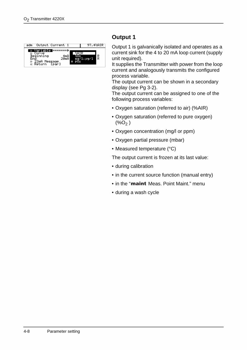
Output 1
Output 1 is galvanically isolated and operates as a current sink for the 4 to 20 mA loop current (supply unit required).It supplies the Transmitter with power from the loop current and analogously transmits the configured process variable.The output current can be shown in a secondary display (see Pg 3-2).The output current can be assigned to one of the following process variables:
• Oxygen saturation (referred to air) (%AIR)
• Oxygen saturation (referred to pure oxygen) (%O2 )
• Oxygen concentration (mg/l or ppm)
• Oxygen partial pressure (mbar)
• Measured temperature (°C)
The output current is frozen at its last value:
• during calibration
• in the current source function (manual entry)
• in the “ Meas. Point Maint.” menu
• during a wash cycle
4-8 Parameter setting
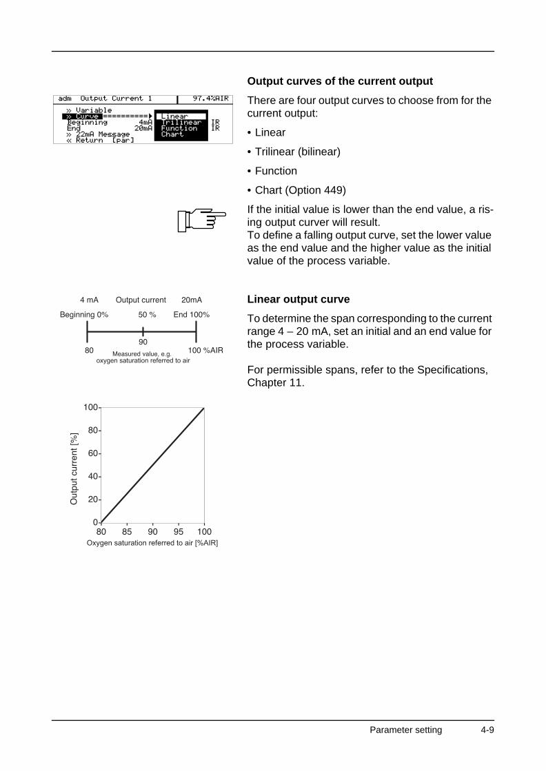
Output curves of the current output
There are four output curves to choose from for the current output:
• Linear
• Trilinear (bilinear)
• Function
• Chart (Option 449)
If the initial value is lower than the end value, a ris-ing output curver will result.To define a falling output curve, set the lower value as the end value and the higher value as the initial value of the process variable.
Linear output curve
To determine the span corresponding to the current range 4 – 20 mA, set an initial and an end value for the process variable.
For permissible spans, refer to the Specifications, Chapter 11.
oxygen saturation referred to air
Oxygen saturation referred to air [%AIR]
Parameter setting 4-9
O2 Transmitter 4220X
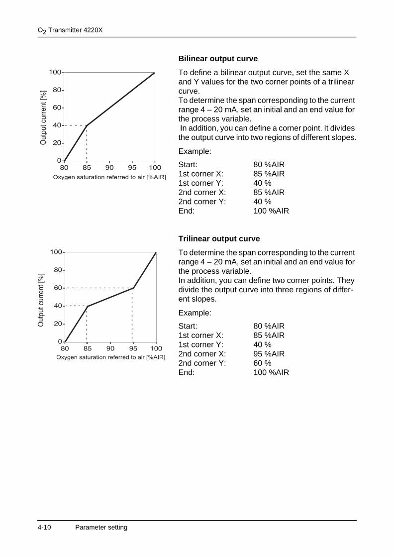
Bilinear output curve
To define a bilinear output curve, set the same X and Y values for the two corner points of a trilinear curve.To determine the span corresponding to the current range 4 – 20 mA, set an initial and an end value for the process variable. In addition, you can define a corner point. It divides the output curve into two regions of different slopes.
Example:
Start: 80 %AIR1st corner X: 85 %AIR1st corner Y: 40 %2nd corner X: 85 %AIR2nd corner Y: 40 %End: 100 %AIR
Trilinear output curve
To determine the span corresponding to the current range 4 – 20 mA, set an initial and an end value for the process variable.In addition, you can define two corner points. They divide the output curve into three regions of differ-ent slopes.
Example:
Start: 80 %AIR1st corner X: 85 %AIR1st corner Y: 40 %2nd corner X: 95 %AIR2nd corner Y: 60 %End: 100 %AIR
Oxygen saturation referred to air [%AIR]
Oxygen saturation referred to air [%AIR]
4-10 Parameter setting
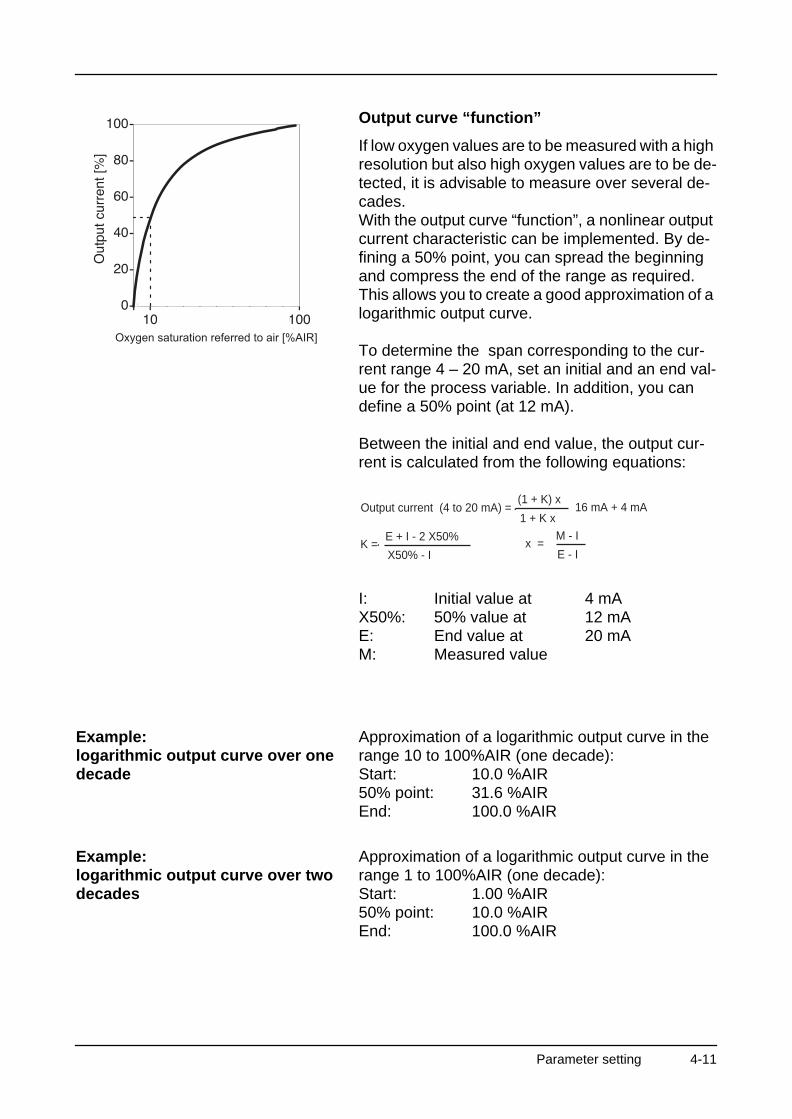
Output curve “function”
If low oxygen values are to be measured with a high resolution but also high oxygen values are to be de-tected, it is advisable to measure over several de-cades.With the output curve “function”, a nonlinear output current characteristic can be implemented. By de-fining a 50% point, you can spread the beginning and compress the end of the range as required.This allows you to create a good approximation of a logarithmic output curve.
To determine the span corresponding to the cur-rent range 4 – 20 mA, set an initial and an end val-ue for the process variable. In addition, you can define a 50% point (at 12 mA).
Between the initial and end value, the output cur-rent is calculated from the following equations:
I: Initial value at 4 mAX50%: 50% value at 12 mAE: End value at 20 mAM: Measured value
Example:logarithmic output curve over one decade
Approximation of a logarithmic output curve in the range 10 to 100%AIR (one decade):Start: 10.0 %AIR50% point: 31.6 %AIREnd: 100.0 %AIR
Example:logarithmic output curve over two decades
Approximation of a logarithmic output curve in the range 1 to 100%AIR (one decade):Start: 1.00 %AIR50% point: 10.0 %AIREnd: 100.0 %AIR
Oxygen saturation referred to air [%AIR]
Output current (4 to 20 mA) = (1 + K) x
1 + K x16 mA + 4 mA
K = E + I - 2 X50%
X50% - Ix =
M - I
E - I
Parameter setting 4-11
O2 Transmitter 4220X
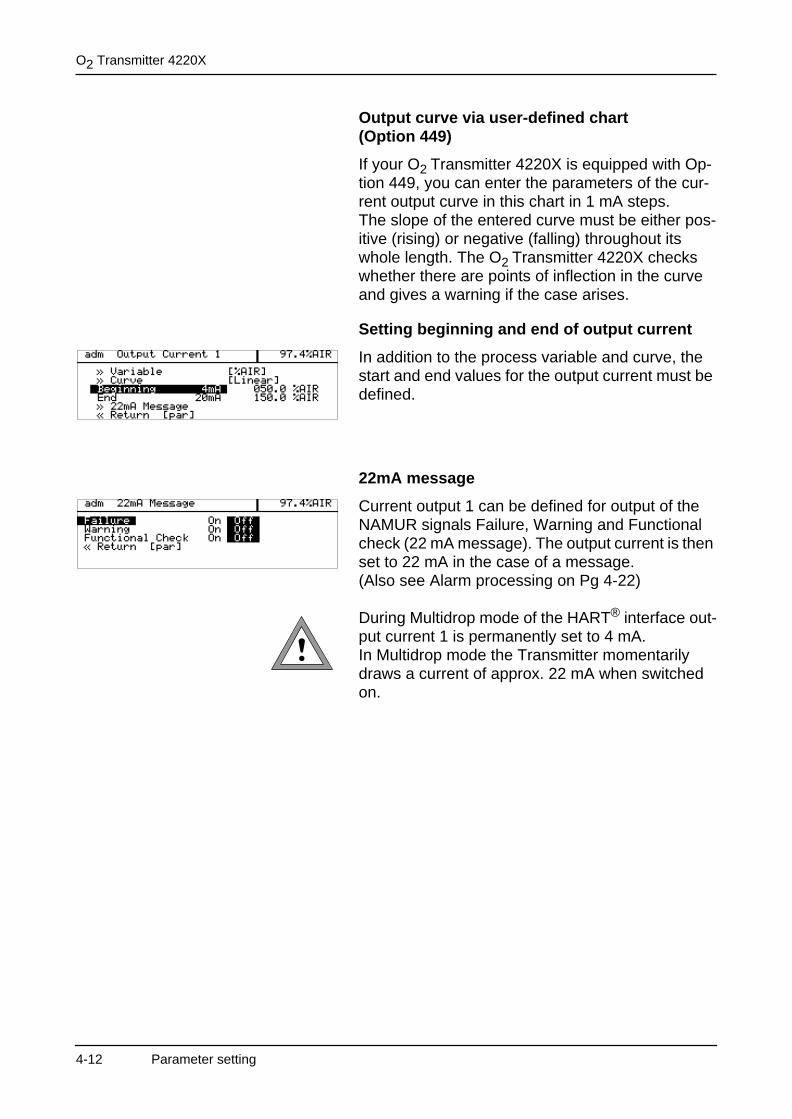
Output curve via user-defined chart (Option 449)
If your O2 Transmitter 4220X is equipped with Op-tion 449, you can enter the parameters of the cur-rent output curve in this chart in 1 mA steps.The slope of the entered curve must be either pos-itive (rising) or negative (falling) throughout its whole length. The O2 Transmitter 4220X checks whether there are points of inflection in the curve and gives a warning if the case arises.
Setting beginning and end of output current
In addition to the process variable and curve, the start and end values for the output current must be defined.
22mA message
Current output 1 can be defined for output of the NAMUR signals Failure, Warning and Functional check (22 mA message). The output current is then set to 22 mA in the case of a message.(Also see Alarm processing on Pg 4-22)
During Multidrop mode of the HART® interface out-put current 1 is permanently set to 4 mA. In Multidrop mode the Transmitter momentarily draws a current of approx. 22 mA when switched on.
4-12 Parameter setting
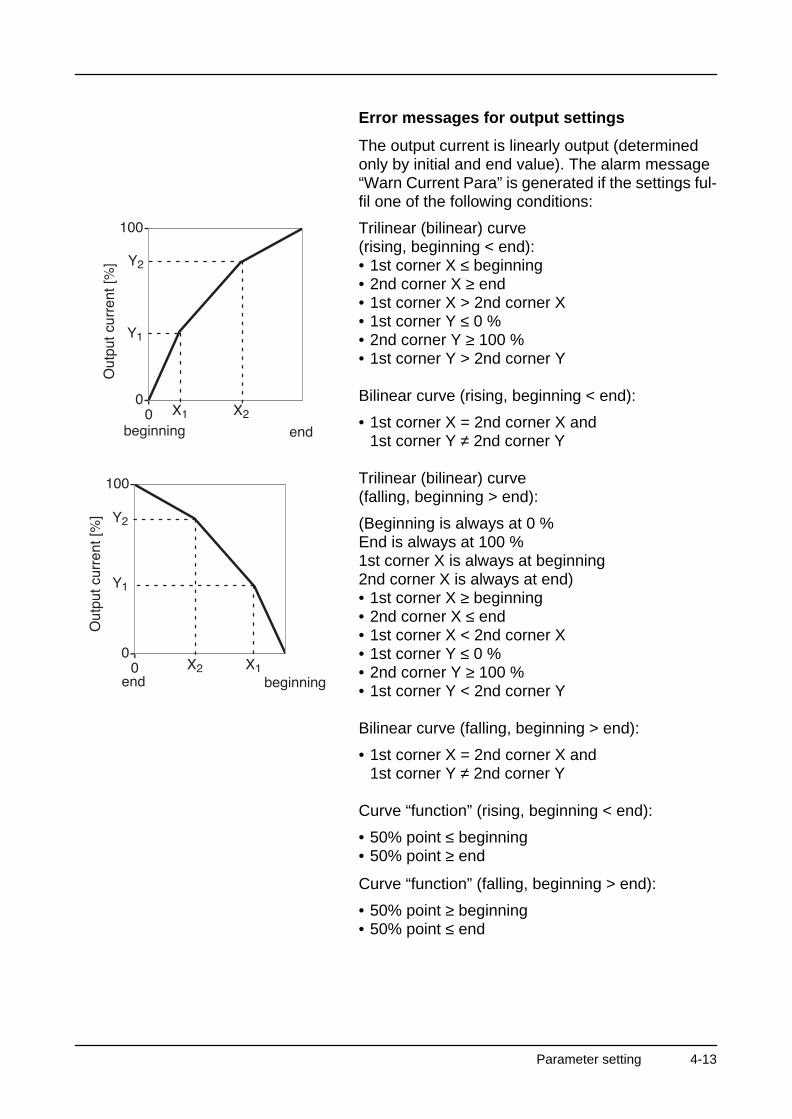
Error messages for output settings
The output current is linearly output (determined only by initial and end value). The alarm message “Warn Current Para” is generated if the settings ful-fil one of the following conditions:
Trilinear (bilinear) curve(rising, beginning < end):• 1st corner X ≤ beginning• 2nd corner X ≥ end• 1st corner X > 2nd corner X• 1st corner Y ≤ 0 %• 2nd corner Y ≥ 100 %• 1st corner Y > 2nd corner Y
Bilinear curve (rising, beginning < end):
• 1st corner X = 2nd corner X and1st corner Y ≠ 2nd corner Y
Trilinear (bilinear) curve(falling, beginning > end):
(Beginning is always at 0 %End is always at 100 %1st corner X is always at beginning2nd corner X is always at end)• 1st corner X ≥ beginning• 2nd corner X ≤ end• 1st corner X < 2nd corner X• 1st corner Y ≤ 0 %• 2nd corner Y ≥ 100 %• 1st corner Y < 2nd corner Y
Bilinear curve (falling, beginning > end):
• 1st corner X = 2nd corner X and1st corner Y ≠ 2nd corner Y
Curve “function” (rising, beginning < end):
• 50% point ≤ beginning• 50% point ≥ end
Curve “function” (falling, beginning > end):
• 50% point ≥ beginning• 50% point ≤ end
Parameter setting 4-13
O2 Transmitter 4220X
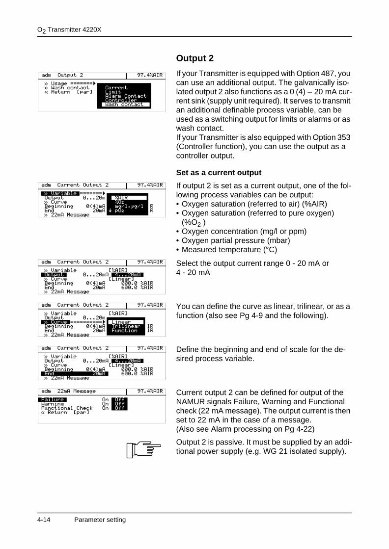
Output 2
If your Transmitter is equipped with Option 487, you can use an additional output. The galvanically iso-lated output 2 also functions as a 0 (4) – 20 mA cur-rent sink (supply unit required). It serves to transmit an additional definable process variable, can be used as a switching output for limits or alarms or as wash contact.If your Transmitter is also equipped with Option 353 (Controller function), you can use the output as a controller output.
Set as a current output
If output 2 is set as a current output, one of the fol-lowing process variables can be output:• Oxygen saturation (referred to air) (%AIR)• Oxygen saturation (referred to pure oxygen)
(%O2 )• Oxygen concentration (mg/l or ppm)• Oxygen partial pressure (mbar)• Measured temperature (°C)
Select the output current range 0 - 20 mA or 4 - 20 mA
You can define the curve as linear, trilinear, or as a function (also see Pg 4-9 and the following).
Define the beginning and end of scale for the de-sired process variable.
Current output 2 can be defined for output of the NAMUR signals Failure, Warning and Functional check (22 mA message). The output current is then set to 22 mA in the case of a message. (Also see Alarm processing on Pg 4-22)
Output 2 is passive. It must be supplied by an addi-tional power supply (e.g. WG 21 isolated supply).
4-14 Parameter setting
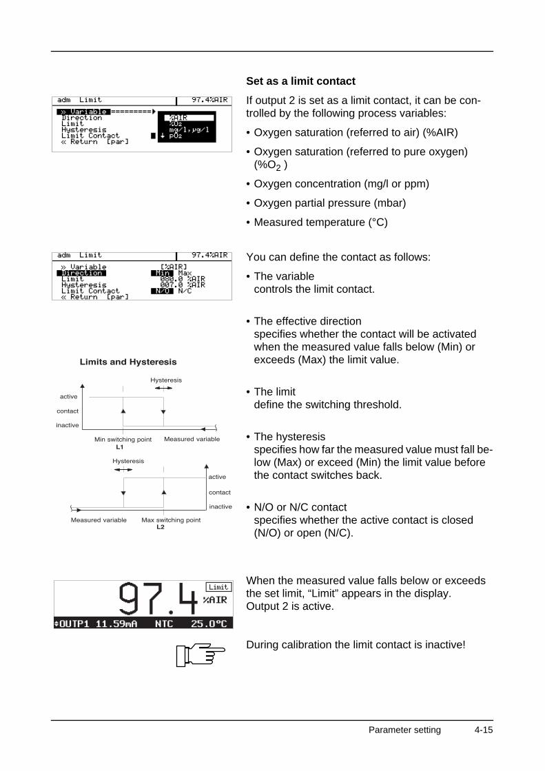
Set as a limit contact
If output 2 is set as a limit contact, it can be con-trolled by the following process variables:
• Oxygen saturation (referred to air) (%AIR)
• Oxygen saturation (referred to pure oxygen) (%O2 )
• Oxygen concentration (mg/l or ppm)
• Oxygen partial pressure (mbar)
• Measured temperature (°C)
You can define the contact as follows:
• The variablecontrols the limit contact.
• The effective directionspecifies whether the contact will be activated when the measured value falls below (Min) or exceeds (Max) the limit value.
• The limitdefine the switching threshold.
• The hysteresisspecifies how far the measured value must fall be-low (Max) or exceed (Min) the limit value before the contact switches back.
• N/O or N/C contactspecifies whether the active contact is closed (N/O) or open (N/C).
When the measured value falls below or exceeds the set limit, “Limit” appears in the display.Output 2 is active.
During calibration the limit contact is inactive!
Parameter setting 4-15
O2 Transmitter 4220X
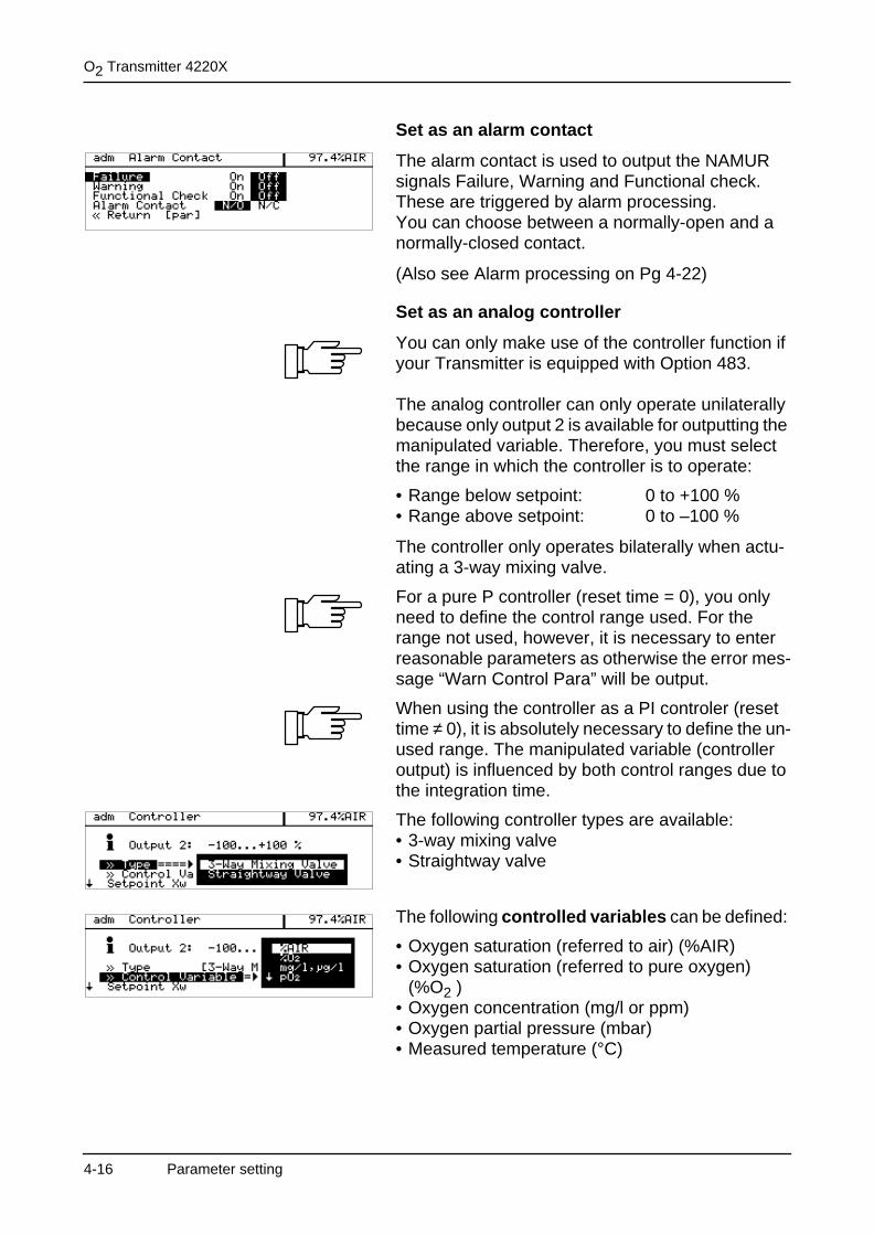
Set as an alarm contact
The alarm contact is used to output the NAMUR signals Failure, Warning and Functional check.These are triggered by alarm processing.You can choose between a normally-open and a normally-closed contact.
(Also see Alarm processing on Pg 4-22)
Set as an analog controller
You can only make use of the controller function if your Transmitter is equipped with Option 483.
The analog controller can only operate unilaterally because only output 2 is available for outputting the manipulated variable. Therefore, you must select the range in which the controller is to operate:
• Range below setpoint: 0 to +100 %• Range above setpoint: 0 to –100 %
The controller only operates bilaterally when actu-ating a 3-way mixing valve.
For a pure P controller (reset time = 0), you only need to define the control range used. For the range not used, however, it is necessary to enter reasonable parameters as otherwise the error mes-sage “Warn Control Para” will be output.
When using the controller as a PI controler (reset time ≠ 0), it is absolutely necessary to define the un-used range. The manipulated variable (controller output) is influenced by both control ranges due to the integration time.
The following controller types are available:• 3-way mixing valve• Straightway valve
The following controlled variables can be defined:
• Oxygen saturation (referred to air) (%AIR)• Oxygen saturation (referred to pure oxygen)
(%O2 ) • Oxygen concentration (mg/l or ppm)• Oxygen partial pressure (mbar)• Measured temperature (°C)
4-16 Parameter setting
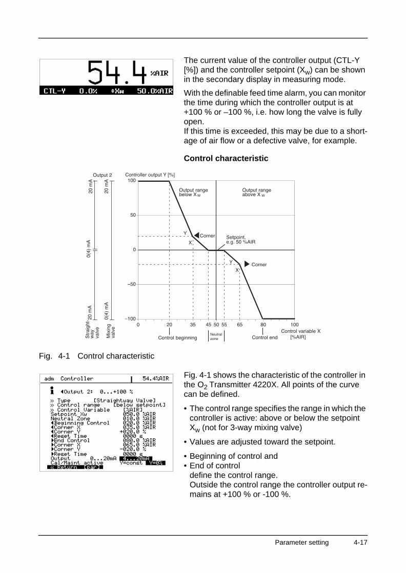
The current value of the controller output (CTL-Y [%]) and the controller setpoint (Xw) can be shown in the secondary display in measuring mode.
With the definable feed time alarm, you can monitor the time during which the controller output is at +100 % or –100 %, i.e. how long the valve is fully open.If this time is exceeded, this may be due to a short-age of air flow or a defective valve, for example.
Control characteristic
Fig. 4-1 Control characteristic
Fig. 4-1 shows the characteristic of the controller in the O2 Transmitter 4220X. All points of the curve can be defined.
• The control range specifies the range in which the controller is active: above or below the setpoint Xw (not for 3-way mixing valve)
• Values are adjusted toward the setpoint.
• Beginning of control and• End of control
define the control range. Outside the control range the controller output re-mains at +100 % or -100 %.
Parameter setting 4-17
O2 Transmitter 4220X
• In the neutral zone no control takes place.The neutral zone is symmetrical to the setpoint and its width can be defined.
• With corner X and corner Y you can define a cor-ner point for each control range ( : controlled variable < setpoint and : Controlled variable > setpoint). This allows you to define two different slopes to obtain an optimal control characteristic for strongly nonlinear curves, for example.
• The reset time specifies the I-action component of the controller. If you set “ Reset Time 0000 s”, the I-action component is turned off. The reset time can be defined separately for both control ranges ( : Controlled variable < setpoint and : Con-trolled variable > setpoint).
• With Cal/Maint active, you select whether the con-troller output is frozen at its last value (Y = const) or whether it goes to 0 % (Y = 0 %) during calibra-tion and maintenance.
For test purposes, you can manually enter the con-troller output Y in the Maintenance menu (see Pg 7-3).
Controller output (manipulated variable)
The manipulated variable (controller output) is out-put via output 2 as a current of either 0 to 20 mA or 4 to 20 mA. The valve type determines the behav-ior of the output current. You can choose between a 3-way mixing valve or a straightway valve.
With the 3-way mixing valve, output 2 operates over the entire control range:• Y = –100 to +100 %
corresponds to 0 (4) to 20 mA
When set as a straightway valve, you must select the output range:
• Control range below setpoint XW:Controller output range 0 to +100 %corresponds to 0 (4) to 20 mA
• Control range above setpoint XW:Controller output range 0 to -100 %corresponds to 0 (4) to 20 mA
The current controller output and the setpoint can be shown in the secondary display (see Pg 3-2).
4-18 Parameter setting
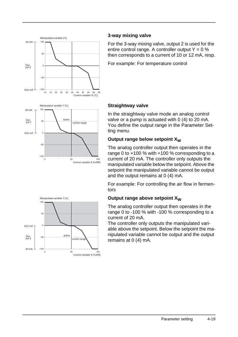
3-way mixing valve
For the 3-way mixing valve, output 2 is used for the entire control range. A controller output Y = 0 % then corresponds to a current of 10 or 12 mA, resp.
For example: For temperature control
Straightway valve
In the straightway valve mode an analog control valve or a pump is actuated with 0 (4) to 20 mA. You define the output range in the Parameter Set-ting menu.
Output range below setpoint XW
The analog controller output then operates in the range 0 to +100 % with +100 % corresponding to a current of 20 mA. The controller only outputs the manipulated variable below the setpoint. Above the setpoint the manipulated variable cannot be output and the output remains at 0 (4) mA.
For example: For controlling the air flow in fermen-tors
Output range above setpoint XW
The analog controller output then operates in the range 0 to -100 % with -100 % corresponding to a current of 20 mA.The controller only outputs the manipulated vari-able above the setpoint. Below the setpoint the ma-nipulated variable cannot be output and the output remains at 0 (4) mA.
Parameter setting 4-19
O2 Transmitter 4220X
Error messages for controller settings
The controller will be switched off (manipulated variable Y = 0 %) and the alarm message “Warn Control Para” will be activated if any of the following conditions applies:
All controller types:
• Beginning ≥ setpoint – neutral zone / 2
• Corner X < beginning
• Corner X > setpoint – neutral zone / 2
• End ≤ setpoint + neutral zone / 2
• Corner X < setpoint + neutral zone / 2
• Corner X > end
• Corner Y>100 %
• Neutral zone < 0
• Corner Y>100 %
With the definable feed time alarm (see Pg 4-21) you can monitor the time during which the controller output is at +100 % or –100 %, i.e. how long the valve is fully open. If this time is exceeded, this may be due to a shortage of air flow or a defective valve, for example.
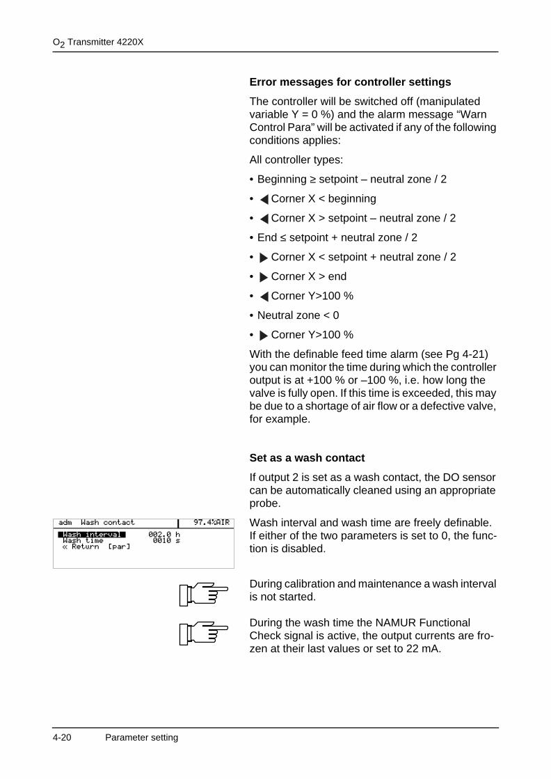
Set as a wash contact
If output 2 is set as a wash contact, the DO sensor can be automatically cleaned using an appropriate probe.
Wash interval and wash time are freely definable. If either of the two parameters is set to 0, the func-tion is disabled.
During calibration and maintenance a wash interval is not started.
During the wash time the NAMUR Functional Check signal is active, the output currents are fro-zen at their last values or set to 22 mA.
4-20 Parameter setting
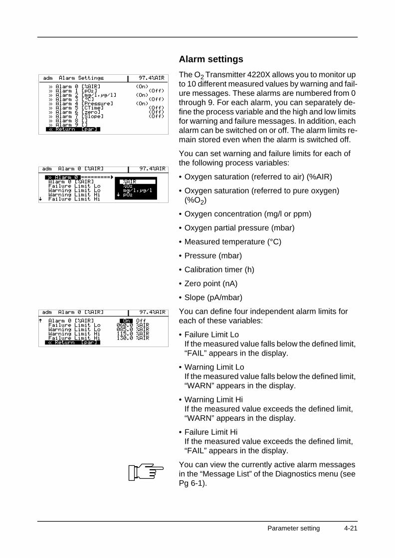
Alarm settings
The O2 Transmitter 4220X allows you to monitor up to 10 different measured values by warning and fail-ure messages. These alarms are numbered from 0 through 9. For each alarm, you can separately de-fine the process variable and the high and low limits for warning and failure messages. In addition, each alarm can be switched on or off. The alarm limits re-main stored even when the alarm is switched off.
You can set warning and failure limits for each of the following process variables:
• Oxygen saturation (referred to air) (%AIR)
• Oxygen saturation (referred to pure oxygen) (%O2)
• Oxygen concentration (mg/l or ppm)
• Oxygen partial pressure (mbar)
• Measured temperature (°C)
• Pressure (mbar)
• Calibration timer (h)
• Zero point (nA)
• Slope (pA/mbar)
You can define four independent alarm limits for each of these variables:
• Failure Limit LoIf the measured value falls below the defined limit, “FAIL” appears in the display.
• Warning Limit LoIf the measured value falls below the defined limit, “WARN” appears in the display.
• Warning Limit HiIf the measured value exceeds the defined limit, “WARN” appears in the display.
• Failure Limit HiIf the measured value exceeds the defined limit, “FAIL” appears in the display.
You can view the currently active alarm messages in the “Message List” of the Diagnostics menu (see Pg 6-1).
Parameter setting 4-21
O2 Transmitter 4220X
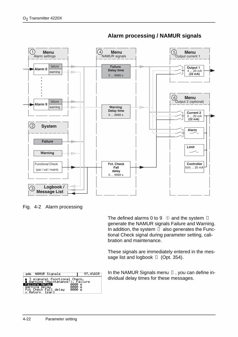
Alarm processing / NAMUR signals
Fig. 4-2 Alarm processing
The defined alarms 0 to 9 and the system generate the NAMUR signals Failure and Warning.In addition, the system also generates the Func-tional Check signal during parameter setting, cali-bration and maintenance.
These signals are immediately entered in the mes-sage list and logbook (Opt. 354).
In the NAMUR Signals menu , you can define in-dividual delay times for these messages.
➁
➁
➂
➃
4-22 Parameter setting

For functional check, the defined delay time acts as a fall delay!This has the advantage that, for example, any tem-perature or measurement settling times following a sensor calibration can be bridged with a corre-spondingly defined fall delay time.
The messages can be output via output current 1 or output 2 (if current 2 is active) as a 22 mA
signal.
To do so, all three messages can be activated sep-arately or in any combination in the 22 mA Message submenu.
If output 2 is set as an alarm contact, it can be used to output these messages. In this menu the alarm contact can be set as a normally open or a normally closed contact.
Cal timer
The cal timer allows you to monitor whether the sensor is calibrated regularly. The cal timer counts the time passed since the last calibration. When the preset time is reached, a message is released.In the “Alarm Settings” menu you can preset one in-terval each for a warning and a failure message.
The cal timer count can be shown in the secondary display (see Pg 3-2).
HART® Communication
With Option 467 “HART® Communication” you can, for example, communicate with the O2 Transmitter 4220X via the loop current using a handheld termi-nal or from the control room. Device data, mea-sured values, messages and parameters are retrievable.
The O2 Transmitter 4220X can be addressed from the master in two different ways: via a long, perma-nent address, which is unique world-wide, or via a selectable short address.
➄ ➅
Parameter setting 4-23
O2 Transmitter 4220X
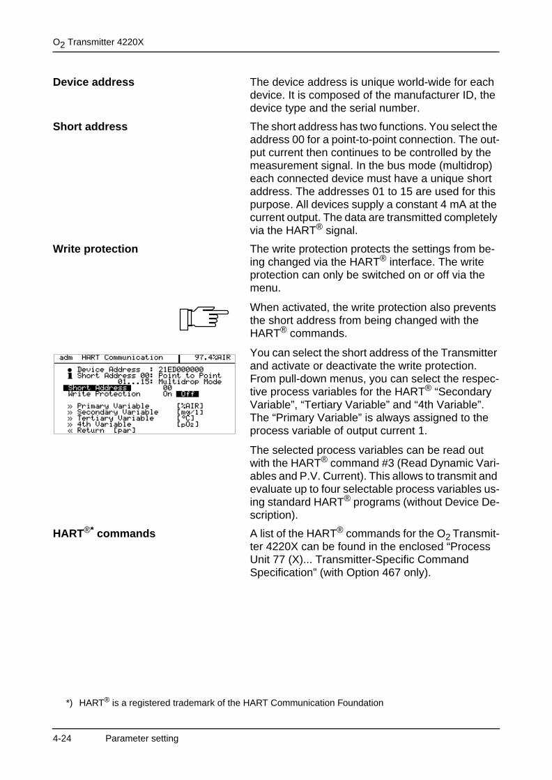
Device address The device address is unique world-wide for each device. It is composed of the manufacturer ID, the device type and the serial number.
Short address The short address has two functions. You select the address 00 for a point-to-point connection. The out-put current then continues to be controlled by the measurement signal. In the bus mode (multidrop) each connected device must have a unique short address. The addresses 01 to 15 are used for this purpose. All devices supply a constant 4 mA at the current output. The data are transmitted completely via the HART® signal.
Write protection The write protection protects the settings from be-ing changed via the HART® interface. The write protection can only be switched on or off via the menu.
When activated, the write protection also prevents the short address from being changed with the HART® commands.
You can select the short address of the Transmitter and activate or deactivate the write protection.From pull-down menus, you can select the respec-tive process variables for the HART® “Secondary Variable”, “Tertiary Variable” and “4th Variable”.The “Primary Variable” is always assigned to the process variable of output current 1.
The selected process variables can be read out with the HART® command #3 (Read Dynamic Vari-ables and P.V. Current). This allows to transmit and evaluate up to four selectable process variables us-ing standard HART® programs (without Device De-scription).
HART®* commands A list of the HART® commands for the O2 Transmit-ter 4220X can be found in the enclosed “ProcessUnit 77 (X)... Transmitter-Specific Command Specification” (with Option 467 only).
*) HART® is a registered trademark of the HART Communication Foundation
4-24 Parameter setting
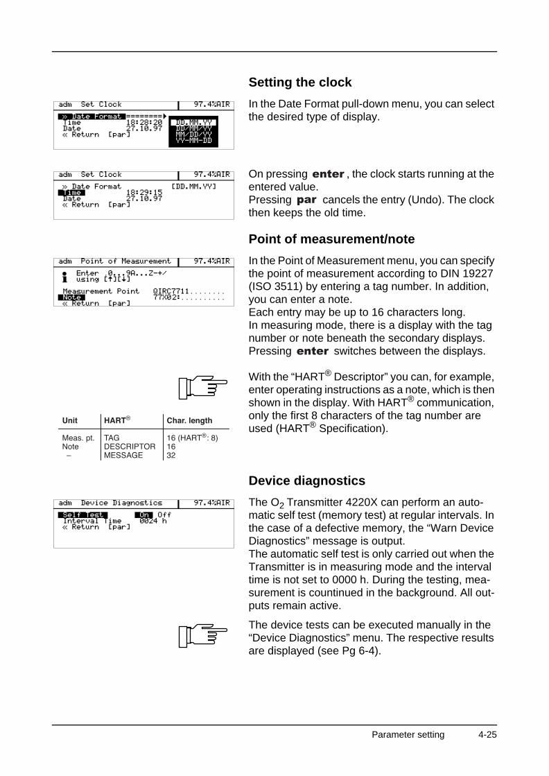
Setting the clock
In the Date Format pull-down menu, you can select the desired type of display.
On pressing , the clock starts running at the entered value.Pressing cancels the entry (Undo). The clock then keeps the old time.
Point of measurement/note
In the Point of Measurement menu, you can specify the point of measurement according to DIN 19227 (ISO 3511) by entering a tag number. In addition, you can enter a note.Each entry may be up to 16 characters long.In measuring mode, there is a display with the tag number or note beneath the secondary displays. Pressing switches between the displays.
With the “HART® Descriptor” you can, for example, enter operating instructions as a note, which is then shown in the display. With HART® communication, only the first 8 characters of the tag number are used (HART® Specification).
Device diagnostics
The O2 Transmitter 4220X can perform an auto-matic self test (memory test) at regular intervals. In the case of a defective memory, the “Warn Device Diagnostics” message is output.The automatic self test is only carried out when the Transmitter is in measuring mode and the interval time is not set to 0000 h. During the testing, mea-surement is countinued in the background. All out-puts remain active.
The device tests can be executed manually in the “Device Diagnostics” menu. The respective results are displayed (see Pg 6-4).
Parameter setting 4-25
O2 Transmitter 4220X
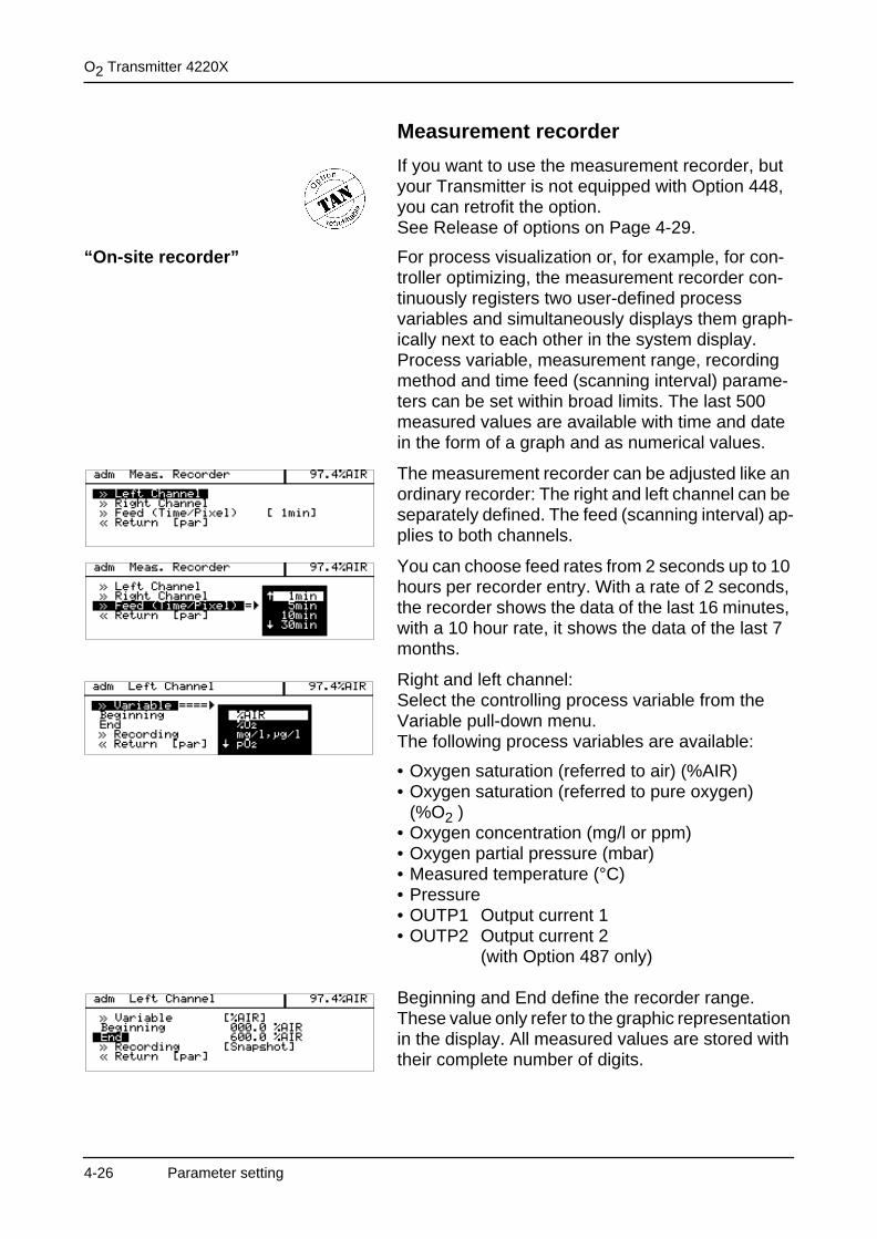
Measurement recorder
If you want to use the measurement recorder, but your Transmitter is not equipped with Option 448, you can retrofit the option. See Release of options on Page 4-29.
“On-site recorder” For process visualization or, for example, for con-troller optimizing, the measurement recorder con-tinuously registers two user-defined process variables and simultaneously displays them graph-ically next to each other in the system display.Process variable, measurement range, recording method and time feed (scanning interval) parame-ters can be set within broad limits. The last 500 measured values are available with time and date in the form of a graph and as numerical values.
The measurement recorder can be adjusted like an ordinary recorder: The right and left channel can be separately defined. The feed (scanning interval) ap-plies to both channels.
You can choose feed rates from 2 seconds up to 10 hours per recorder entry. With a rate of 2 seconds, the recorder shows the data of the last 16 minutes, with a 10 hour rate, it shows the data of the last 7 months.
Right and left channel:Select the controlling process variable from the Variable pull-down menu. The following process variables are available:
• Oxygen saturation (referred to air) (%AIR)• Oxygen saturation (referred to pure oxygen)
(%O2 ) • Oxygen concentration (mg/l or ppm)• Oxygen partial pressure (mbar)• Measured temperature (°C)• Pressure• OUTP1 Output current 1• OUTP2 Output current 2
(with Option 487 only)
Beginning and End define the recorder range. These value only refer to the graphic representation in the display. All measured values are stored with their complete number of digits.
4-26 Parameter setting
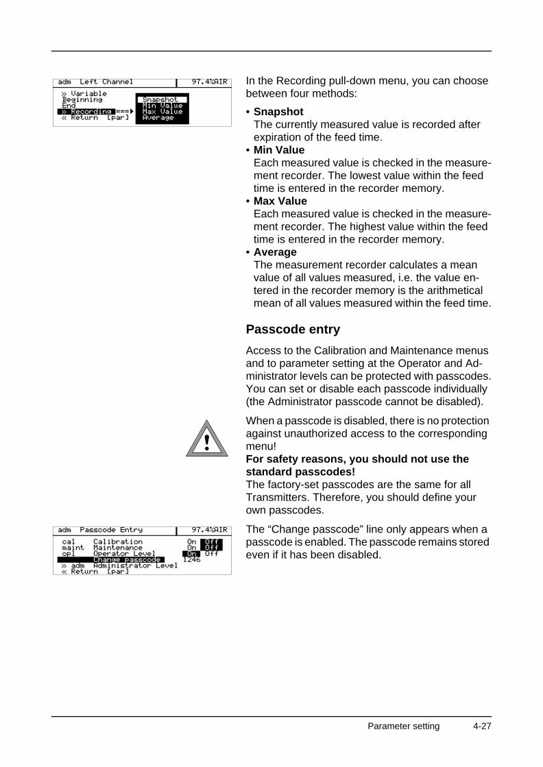
In the Recording pull-down menu, you can choose between four methods:
• SnapshotThe currently measured value is recorded after expiration of the feed time.
• Min ValueEach measured value is checked in the measure-ment recorder. The lowest value within the feed time is entered in the recorder memory.
• Max ValueEach measured value is checked in the measure-ment recorder. The highest value within the feed time is entered in the recorder memory.
• AverageThe measurement recorder calculates a mean value of all values measured, i.e. the value en-tered in the recorder memory is the arithmetical mean of all values measured within the feed time.
Passcode entry
Access to the Calibration and Maintenance menus and to parameter setting at the Operator and Ad-ministrator levels can be protected with passcodes.You can set or disable each passcode individually (the Administrator passcode cannot be disabled).
When a passcode is disabled, there is no protection against unauthorized access to the corresponding menu!For safety reasons, you should not use the standard passcodes!The factory-set passcodes are the same for all Transmitters. Therefore, you should define your own passcodes.
The “Change passcode” line only appears when a passcode is enabled. The passcode remains stored even if it has been disabled.
Parameter setting 4-27
O2 Transmitter 4220X
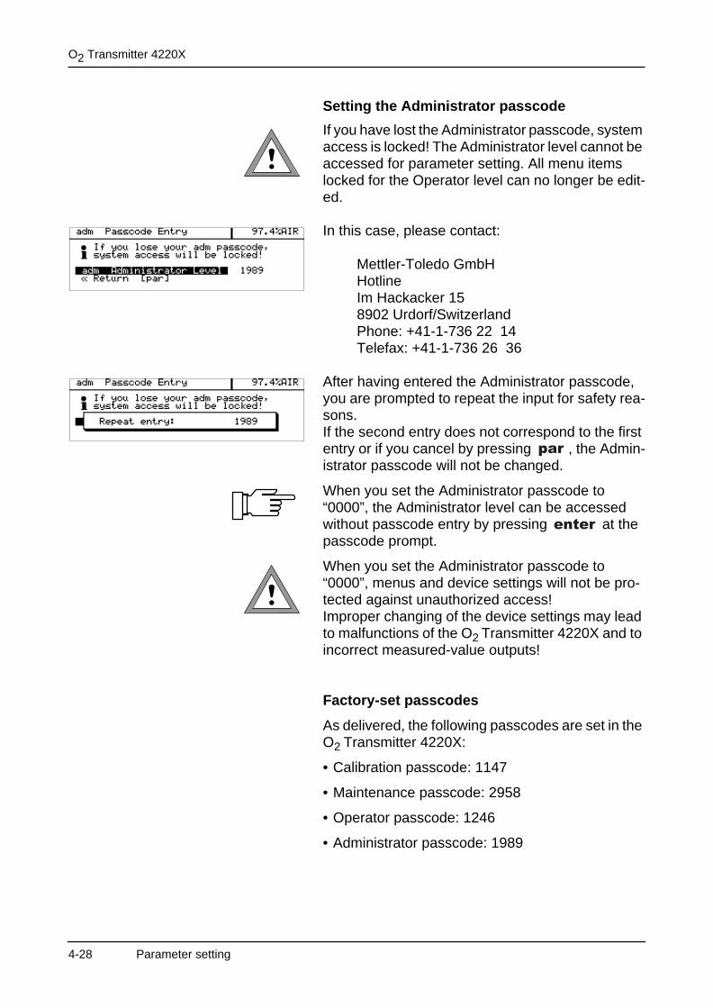
Setting the Administrator passcode
If you have lost the Administrator passcode, system access is locked! The Administrator level cannot be accessed for parameter setting. All menu items locked for the Operator level can no longer be edit-ed.
In this case, please contact:
Mettler-Toledo GmbH HotlineIm Hackacker 158902 Urdorf/SwitzerlandPhone: +41-1-736 22 14Telefax: +41-1-736 26 36
After having entered the Administrator passcode, you are prompted to repeat the input for safety rea-sons.If the second entry does not correspond to the first entry or if you cancel by pressing , the Admin-istrator passcode will not be changed.
When you set the Administrator passcode to “0000”, the Administrator level can be accessed without passcode entry by pressing at the passcode prompt.
When you set the Administrator passcode to “0000”, menus and device settings will not be pro-tected against unauthorized access!Improper changing of the device settings may lead to malfunctions of the O2 Transmitter 4220X and to incorrect measured-value outputs!
Factory-set passcodes
As delivered, the following passcodes are set in the O2 Transmitter 4220X:
• Calibration passcode: 1147
• Maintenance passcode: 2958
• Operator passcode: 1246
• Administrator passcode: 1989
4-28 Parameter setting
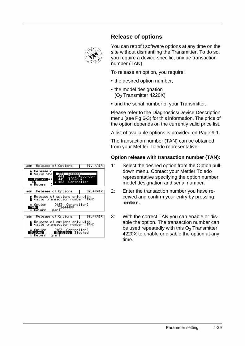
Release of options
You can retrofit software options at any time on the site without dismantling the Transmitter. To do so, you require a device-specific, unique transaction number (TAN).
To release an option, you require:
• the desired option number,
• the model designation(O2 Transmitter 4220X)
• and the serial number of your Transmitter.
Please refer to the Diagnostics/Device Description menu (see Pg 6-3) for this information. The price of the option depends on the currently valid price list.
A list of available options is provided on Page 9-1.
The transaction number (TAN) can be obtained from your Mettler Toledo representative.
Option release with transaction number (TAN):
1: Select the desired option from the Option pull-down menu. Contact your Mettler Toledo representative specifying the option number, model designation and serial number.
2: Enter the transaction number you have re-ceived and confirm your entry by pressing
.
3: With the correct TAN you can enable or dis-able the option. The transaction number can be used repeatedly with this O2 Transmitter 4220X to enable or disable the option at any time.
Parameter setting 4-29

O2 Transmitter 4220X
This page has been left empty for technical reasons.
4-30 Parameter setting
5 Calibration
Why do you have to calibrate?
Every dissolved oxygen sensor has its individual slope and zero point. Both values are altered, for example, by electrolyte consumption. For sufficient-ly high accuracy of oxygen measurement, the Transmitter must be regularly adjusted for the sen-sor data (calibration).
Calibration medium is water with a known oxygen saturation (referred to air) or air. The sensor is im-mersed in the calibration medium.Then the O2 Transmitter 4220X measures the sen-sor current and medium temperature and automat-ically calculates the sensor slope and zero point.
Without calibration every dissolved oxygen meter delivers an imprecise or wrong output value! Particularly after having replaced the sensor, elec-trolyte or sensor membrane, you must perform a calibration.
Monitoring functions for calibration
The O2 Transmitter 4220X provides functions for monitoring proper calibration performance and the sensor condition. This allows documentation for quality management to ISO 9000 and GMP.
• Sensocheck® recognizes mechanical stress of the membrane that might modify the calibration data.
• Regular calibration can be monitored by the cal timer (see Pg 4-23).
• The calibration record provides all relevant data of the last calibration (GMP) (see Pg 6-1).
• The sensor statistics show the behavior of the sensor parameters during the last three calibra-tions compared to the first calibration (see Pg 6-2).
• The logbook provides time and date stamped records of calibrations performed within the last 200 events (see Pg 6-3).
Calibration 5-1
O2 Transmitter 4220X
• You can define limits for warning and failure mes-sages for the sensor slope and zero point (see Pg 4-21). This permits automatic monitoring of the sensor state using the calibration data.
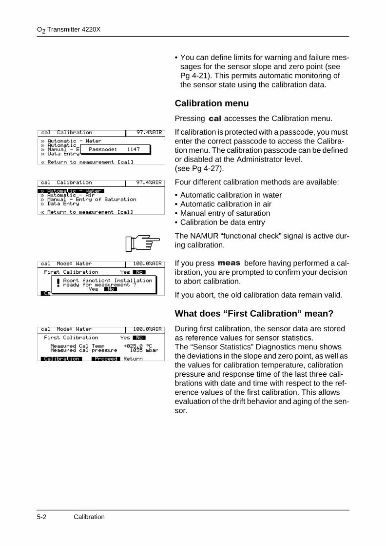
Calibration menu
Pressing accesses the Calibration menu.
If calibration is protected with a passcode, you must enter the correct passcode to access the Calibra-tion menu. The calibration passcode can be defined or disabled at the Administrator level.(see Pg 4-27).
Four different calibration methods are available:
• Automatic calibration in water• Automatic calibration in air• Manual entry of saturation• Calibration be data entry
The NAMUR “functional check” signal is active dur-ing calibration.
If you press before having performed a cal-ibration, you are prompted to confirm your decision to abort calibration.
If you abort, the old calibration data remain valid.
What does “First Calibration” mean?
During first calibration, the sensor data are stored as reference values for sensor statistics.The “Sensor Statistics” Diagnostics menu shows the deviations in the slope and zero point, as well as the values for calibration temperature, calibration pressure and response time of the last three cali-brations with date and time with respect to the ref-erence values of the first calibration. This allows evaluation of the drift behavior and aging of the sen-sor.
5-2 Calibration
When do you have to perform a First Calibra-tion?
Each time the sensor, electrolyte or membrane is replaced, a First Calibration must be performed.
How do you perform a First Calibration?
Select the corresponding calibration method, set “First Calibration Yes” and confirm with .
If you do not want to perform a First Calibration, press to proceed to the next step of the cal-ibration sequence.
One-point or two-point calibration?
For the calibration methods
• Automatic – Water
• Automatic – Air
you can choose between one- and two-point cali-bration.
One-point calibration
The sensor is only calibrated using 100 % medium.This determines the present slope of the sensor.The old zero point remains unchanged.
One-point calibration is sufficient for most of the cases.
Two-point calibration
The sensor is calibrated using two media with dif-ferent oxygen saturation values (100 % and 0 %).This determines the slope and zero point of the sen-sor.
Two-point calibration is only necessary if the mea-sured oxygen value is low or near the sensor zero.
Calibration 5-3
O2 Transmitter 4220X
Automatic calibration in water or air
Calibration can be performed as one- or two-point calibration either in water or in air.The calibration value is always the oxygen satura-tion (referred to air).First, the slope is corrected using the 100 % value.Then, also a zero-point correction can be carried out using the 0 % value.
All calibration data are converted using a reference temperature of 25 °C.During calibration, the NAMUR functional check signal is active, the output currents are frozen at their last values, the limit contact is inactive, the controller output can either be frozen or set to zero (see Pg 4-18), a wash interval is not started.
What you have to know for calibration
For calibration in water:
• Ensure sufficient medium flow to the sensor.
• The calibration medium must be in equilibrium with air. Oxygen exchange between water and air is very slow. Therefore, it takes a relatively long time until water is saturated with atmospheric ox-ygen.
For calibration in air:
• The sensor membrane must be dry, as adhering water drops falsify the measured oxygen value.
Make sure that the oxygen saturation of the calibra-tion medium is correct and remains constant during calibration.Ensure that all other parameters, e.g. temperature and pressure, are constant.
5-4 Calibration
If there is a temperature difference between the cal-ibration medium and the measured medium, the sensor must be kept in the respective medium for several minutes before and after calibration in order to deliver stable measured values.
The type of calibration pressure detection is preset during parameter setting (see Pg 4-4).
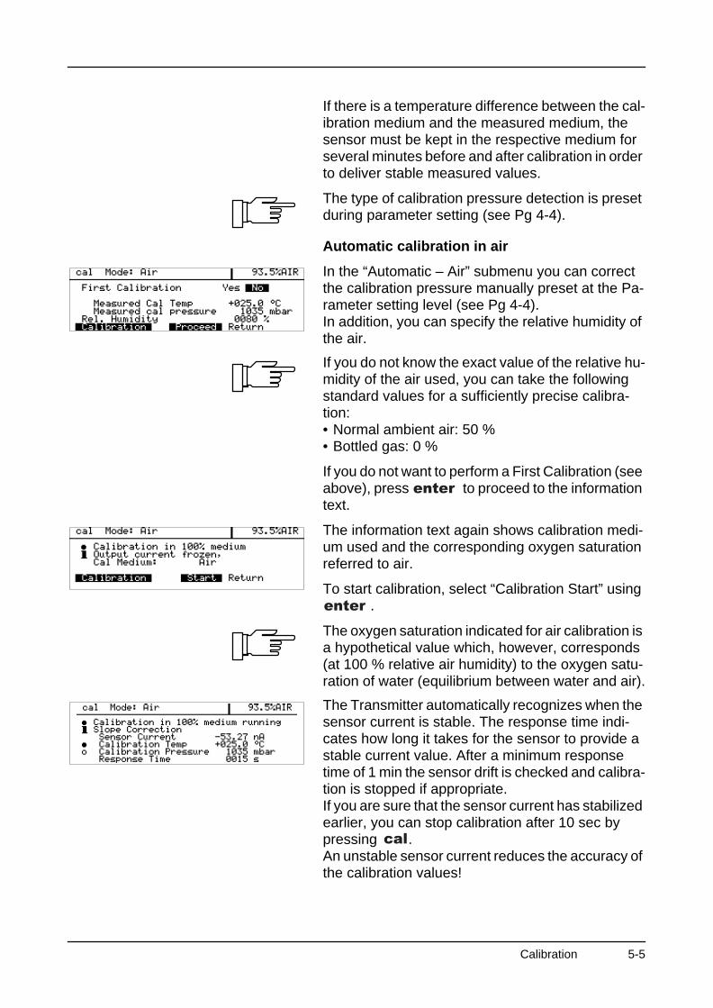
Automatic calibration in air
In the “Automatic – Air” submenu you can correct the calibration pressure manually preset at the Pa-rameter setting level (see Pg 4-4).In addition, you can specify the relative humidity of the air.
If you do not know the exact value of the relative hu-midity of the air used, you can take the following standard values for a sufficiently precise calibra-tion:• Normal ambient air: 50 %• Bottled gas: 0 %
If you do not want to perform a First Calibration (see above), press to proceed to the information text.
The information text again shows calibration medi-um used and the corresponding oxygen saturation referred to air.
To start calibration, select “Calibration Start” using .
The oxygen saturation indicated for air calibration is a hypothetical value which, however, corresponds (at 100 % relative air humidity) to the oxygen satu-ration of water (equilibrium between water and air).
The Transmitter automatically recognizes when the sensor current is stable. The response time indi-cates how long it takes for the sensor to provide a stable current value. After a minimum response time of 1 min the sensor drift is checked and calibra-tion is stopped if appropriate.If you are sure that the sensor current has stabilized earlier, you can stop calibration after 10 sec by pressing .An unstable sensor current reduces the accuracy of the calibration values!
Calibration 5-5
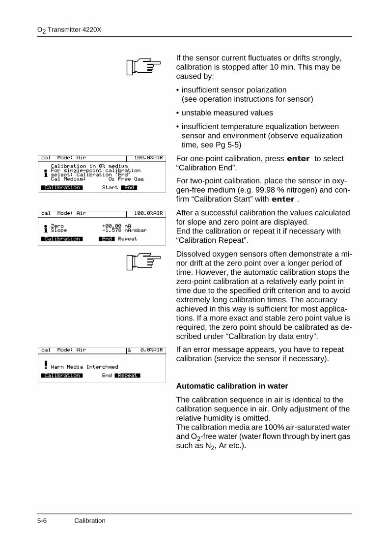
O2 Transmitter 4220X
If the sensor current fluctuates or drifts strongly, calibration is stopped after 10 min. This may be caused by:
• insufficient sensor polarization(see operation instructions for sensor)
• unstable measured values
• insufficient temperature equalization between sensor and environment (observe equalization time, see Pg 5-5)
For one-point calibration, press to select “Calibration End”.
For two-point calibration, place the sensor in oxy-gen-free medium (e.g. 99.98 % nitrogen) and con-firm “Calibration Start” with .
After a successful calibration the values calculated for slope and zero point are displayed.End the calibration or repeat it if necessary with “Calibration Repeat”.
Dissolved oxygen sensors often demonstrate a mi-nor drift at the zero point over a longer period of time. However, the automatic calibration stops the zero-point calibration at a relatively early point in time due to the specified drift criterion and to avoid extremely long calibration times. The accuracy achieved in this way is sufficient for most applica-tions. If a more exact and stable zero point value is required, the zero point should be calibrated as de-scribed under “Calibration by data entry”.
If an error message appears, you have to repeat calibration (service the sensor if necessary).
Automatic calibration in water
The calibration sequence in air is identical to the calibration sequence in air. Only adjustment of the relative humidity is omitted.The calibration media are 100% air-saturated water and O2-free water (water flown through by inert gas such as N2, Ar etc.).
5-6 Calibration
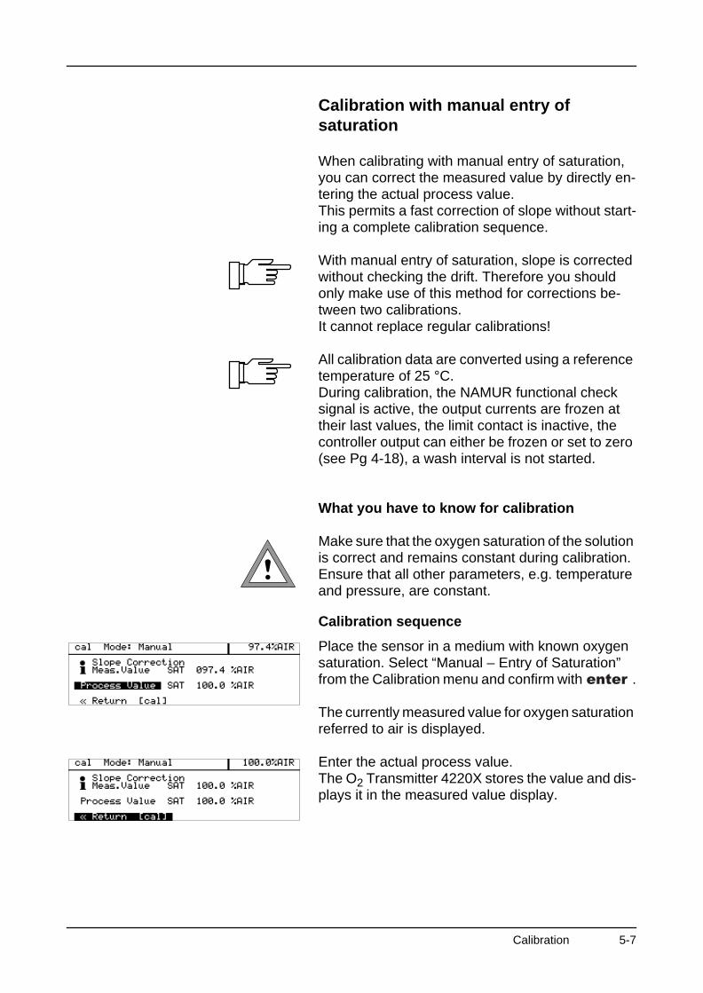
Calibration with manual entry of saturation
When calibrating with manual entry of saturation, you can correct the measured value by directly en-tering the actual process value. This permits a fast correction of slope without start-ing a complete calibration sequence.
With manual entry of saturation, slope is corrected without checking the drift. Therefore you should only make use of this method for corrections be-tween two calibrations.It cannot replace regular calibrations!
All calibration data are converted using a reference temperature of 25 °C.During calibration, the NAMUR functional check signal is active, the output currents are frozen at their last values, the limit contact is inactive, the controller output can either be frozen or set to zero (see Pg 4-18), a wash interval is not started.
What you have to know for calibration
Make sure that the oxygen saturation of the solution is correct and remains constant during calibration.Ensure that all other parameters, e.g. temperature and pressure, are constant.
Calibration sequence
Place the sensor in a medium with known oxygen saturation. Select “Manual – Entry of Saturation” from the Calibration menu and confirm with .
The currently measured value for oxygen saturation referred to air is displayed.
Enter the actual process value. The O2 Transmitter 4220X stores the value and dis-plays it in the measured value display.
Calibration 5-7
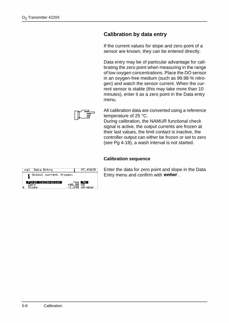
O2 Transmitter 4220X
Calibration by data entry
If the current values for slope and zero point of a sensor are known, they can be entered directly.
Data entry may be of particular advantage for cali-brating the zero point when measuring in the range of low oxygen concentrations. Place the DO sensor in an oxygen-free medium (such as 99.98 % nitro-gen) and watch the sensor current. When the cur-rent sensor is stable (this may take more than 10 minutes), enter it as a zero point in the Data entry menu.
All calibration data are converted using a reference temperature of 25 °C.During calibration, the NAMUR functional check signal is active, the output currents are frozen at their last values, the limit contact is inactive, the controller output can either be frozen or set to zero (see Pg 4-18), a wash interval is not started.
Calibration sequence
Enter the data for zero point and slope in the Data Entry menu and confirm with .
5-8 Calibration
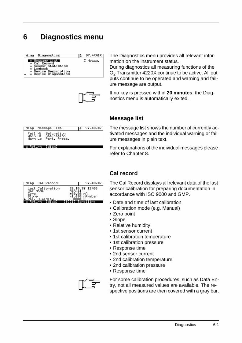
6 Diagnostics menu
The Diagnostics menu provides all relevant infor-mation on the instrument status.During diagnostics all measuring functions of the O2 Transmitter 4220X continue to be active. All out-puts continue to be operated and warning and fail-ure message are output.
If no key is pressed within 20 minutes, the Diag-nostics menu is automatically exited.
Message list
The message list shows the number of currently ac-tivated messages and the individual warning or fail-ure messages in plain text.
For explanations of the individual messages please refer to Chapter 8.
Cal record
The Cal Record displays all relevant data of the last sensor calibration for preparing documentation in accordance with ISO 9000 and GMP.
• Date and time of last calibration• Calibration mode (e.g. Manual)• Zero point• Slope• Relative humidity• 1st sensor current• 1st calibration temperature• 1st calibration pressure• Response time• 2nd sensor current• 2nd calibration temperature• 2nd calibration pressure• Response time
For some calibration procedures, such as Data En-try, not all measured values are available. The re-spective positions are then covered with a gray bar.
Diagnostics 6-1
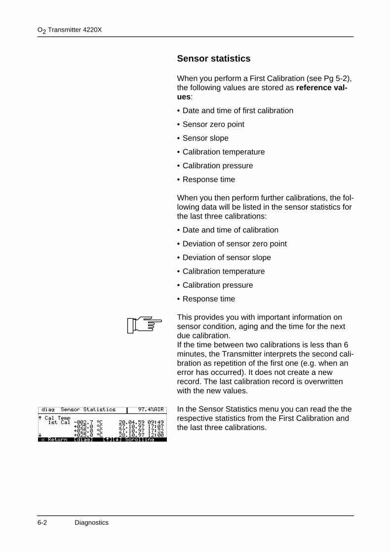
O2 Transmitter 4220X
Sensor statistics
When you perform a First Calibration (see Pg 5-2), the following values are stored as reference val-ues:
• Date and time of first calibration
• Sensor zero point
• Sensor slope
• Calibration temperature
• Calibration pressure
• Response time
When you then perform further calibrations, the fol-lowing data will be listed in the sensor statistics for the last three calibrations:
• Date and time of calibration
• Deviation of sensor zero point
• Deviation of sensor slope
• Calibration temperature
• Calibration pressure
• Response time
This provides you with important information on sensor condition, aging and the time for the next due calibration.If the time between two calibrations is less than 6 minutes, the Transmitter interprets the second cali-bration as repetition of the first one (e.g. when an error has occurred). It does not create a new record. The last calibration record is overwritten with the new values.
In the Sensor Statistics menu you can read the the respective statistics from the First Calibration and the last three calibrations.
6-2 Diagnostics
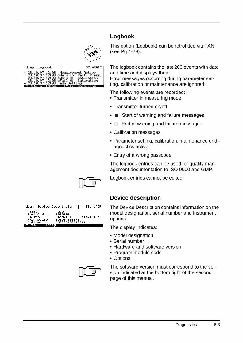
Logbook
This option (Logbook) can be retrofitted via TAN (see Pg 4-29).
The logbook contains the last 200 events with date and time and displays them. Error messages occurring during parameter set-ting, calibration or maintenance are ignored.
The following events are recorded:• Transmitter in measuring mode
• Transmitter turned on/off
• : Start of warning and failure messages
• : End of warning and failure messages
• Calibration messages
• Parameter setting, calibration, maintenance or di-agnostics active
• Entry of a wrong passcode
The logbook entries can be used for quality man-agement documentation to ISO 9000 and GMP.
Logbook entries cannot be edited!
Device description
The Device Description contains information on the model designation, serial number and instrument options.
The display indicates:
• Model designation• Serial number• Hardware and software version• Program module code• Options
The software version must correspond to the ver-sion indicated at the bottom right of the second page of this manual.
Diagnostics 6-3
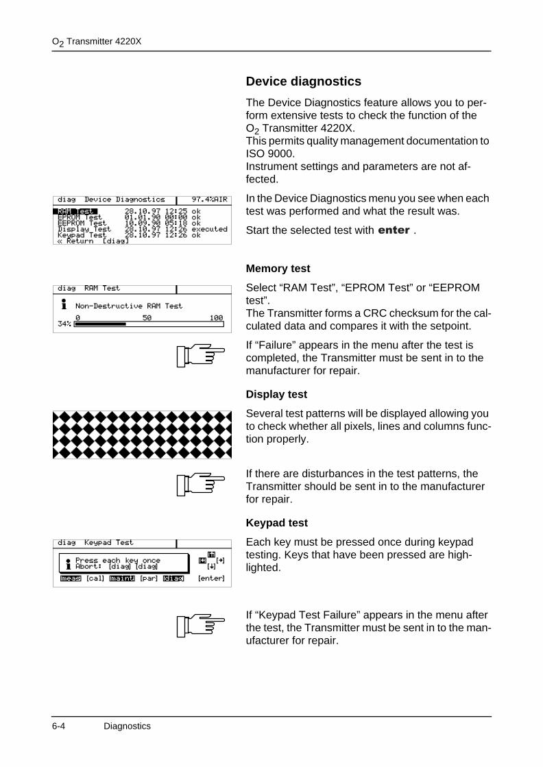
O2 Transmitter 4220X
Device diagnostics
The Device Diagnostics feature allows you to per-form extensive tests to check the function of the O2 Transmitter 4220X.This permits quality management documentation to ISO 9000.Instrument settings and parameters are not af-fected.
In the Device Diagnostics menu you see when each test was performed and what the result was.
Start the selected test with .
Memory test
Select “RAM Test”, “EPROM Test” or “EEPROM test”.The Transmitter forms a CRC checksum for the cal-culated data and compares it with the setpoint.
If “Failure” appears in the menu after the test is completed, the Transmitter must be sent in to the manufacturer for repair.
Display test
Several test patterns will be displayed allowing you to check whether all pixels, lines and columns func-tion properly.
If there are disturbances in the test patterns, the Transmitter should be sent in to the manufacturer for repair.
Keypad test
Each key must be pressed once during keypad testing. Keys that have been pressed are high-lighted.
If “Keypad Test Failure” appears in the menu after the test, the Transmitter must be sent in to the man-ufacturer for repair.
6-4 Diagnostics
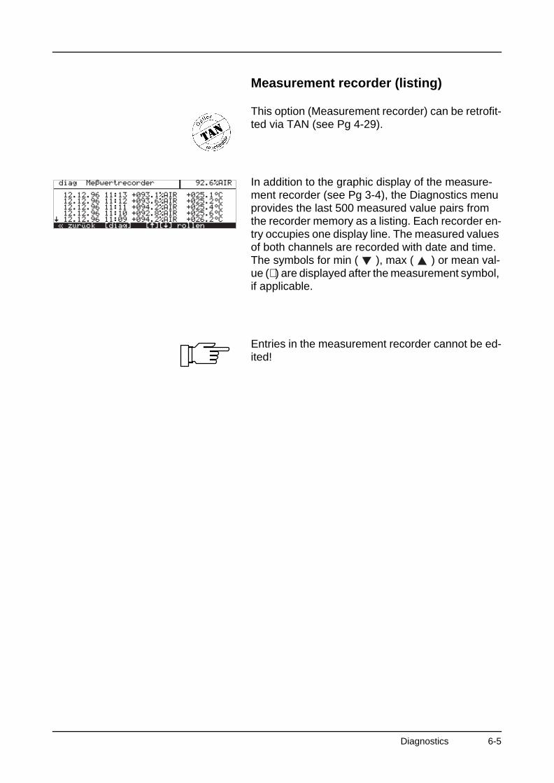
Measurement recorder (listing)
This option (Measurement recorder) can be retrofit-ted via TAN (see Pg 4-29).
In addition to the graphic display of the measure-ment recorder (see Pg 3-4), the Diagnostics menu provides the last 500 measured value pairs from the recorder memory as a listing. Each recorder en-try occupies one display line. The measured values of both channels are recorded with date and time. The symbols for min ( ), max ( ) or mean val-ue (∼ ) are displayed after the measurement symbol, if applicable.
Entries in the measurement recorder cannot be ed-ited!
Diagnostics 6-5

O2 Transmitter 4220X
This page has been left empty for technical reasons.
6-6 Diagnostics
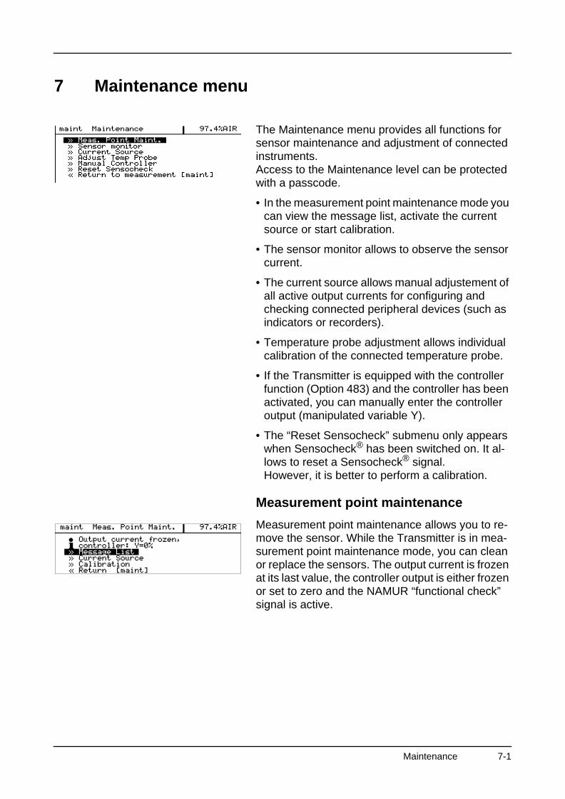
7 Maintenance menu
The Maintenance menu provides all functions for sensor maintenance and adjustment of connected instruments.Access to the Maintenance level can be protected with a passcode.
• In the measurement point maintenance mode you can view the message list, activate the current source or start calibration.
• The sensor monitor allows to observe the sensor current.
• The current source allows manual adjustement of all active output currents for configuring and checking connected peripheral devices (such as indicators or recorders).
• Temperature probe adjustment allows individual calibration of the connected temperature probe.
• If the Transmitter is equipped with the controller function (Option 483) and the controller has been activated, you can manually enter the controller output (manipulated variable Y).
• The “Reset Sensocheck” submenu only appears when Sensocheck® has been switched on. It al-lows to reset a Sensocheck® signal.However, it is better to perform a calibration.
Measurement point maintenance
Measurement point maintenance allows you to re-move the sensor. While the Transmitter is in mea-surement point maintenance mode, you can clean or replace the sensors. The output current is frozen at its last value, the controller output is either frozen or set to zero and the NAMUR “functional check” signal is active.
Maintenance 7-1
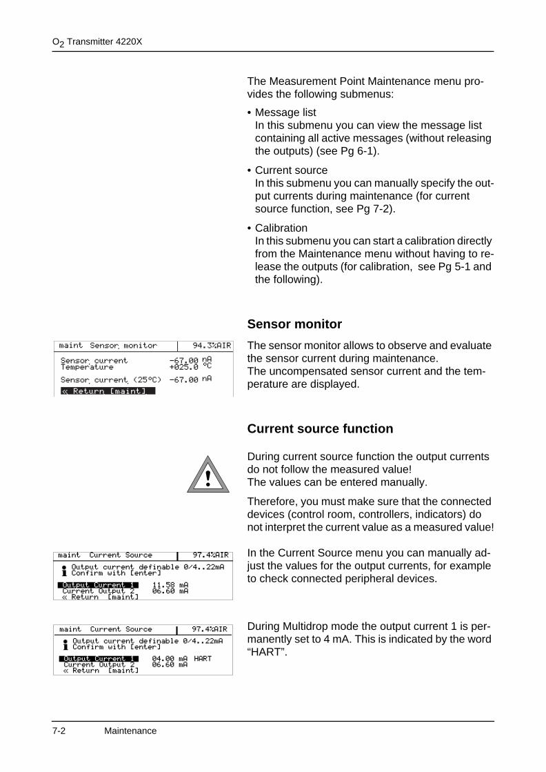
O2 Transmitter 4220X
The Measurement Point Maintenance menu pro-vides the following submenus:
• Message listIn this submenu you can view the message list containing all active messages (without releasing the outputs) (see Pg 6-1).
• Current sourceIn this submenu you can manually specify the out-put currents during maintenance (for current source function, see Pg 7-2).
• CalibrationIn this submenu you can start a calibration directly from the Maintenance menu without having to re-lease the outputs (for calibration, see Pg 5-1 and the following).
Sensor monitor
The sensor monitor allows to observe and evaluate the sensor current during maintenance.The uncompensated sensor current and the tem-perature are displayed.
Current source function
During current source function the output currents do not follow the measured value! The values can be entered manually.
Therefore, you must make sure that the connected devices (control room, controllers, indicators) do not interpret the current value as a measured value!
In the Current Source menu you can manually ad-just the values for the output currents, for example to check connected peripheral devices.
During Multidrop mode the output current 1 is per-manently set to 4 mA. This is indicated by the word “HART”.
7-2 Maintenance
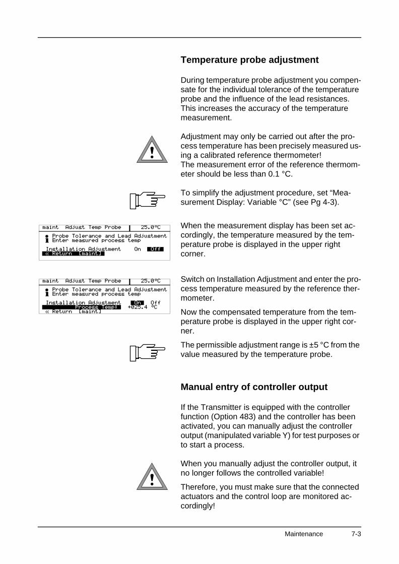
Temperature probe adjustment
During temperature probe adjustment you compen-sate for the individual tolerance of the temperature probe and the influence of the lead resistances. This increases the accuracy of the temperature measurement.
Adjustment may only be carried out after the pro-cess temperature has been precisely measured us-ing a calibrated reference thermometer!The measurement error of the reference thermom-eter should be less than 0.1 °C.
To simplify the adjustment procedure, set “Mea-surement Display: Variable °C” (see Pg 4-3).
When the measurement display has been set ac-cordingly, the temperature measured by the tem-perature probe is displayed in the upper right corner.
Switch on Installation Adjustment and enter the pro-cess temperature measured by the reference ther-mometer.
Now the compensated temperature from the tem-perature probe is displayed in the upper right cor-ner.
The permissible adjustment range is ±5 °C from the value measured by the temperature probe.
Manual entry of controller output
If the Transmitter is equipped with the controller function (Option 483) and the controller has been activated, you can manually adjust the controller output (manipulated variable Y) for test purposes or to start a process.
When you manually adjust the controller output, it no longer follows the controlled variable!
Therefore, you must make sure that the connected actuators and the control loop are monitored ac-cordingly!
Maintenance 7-3
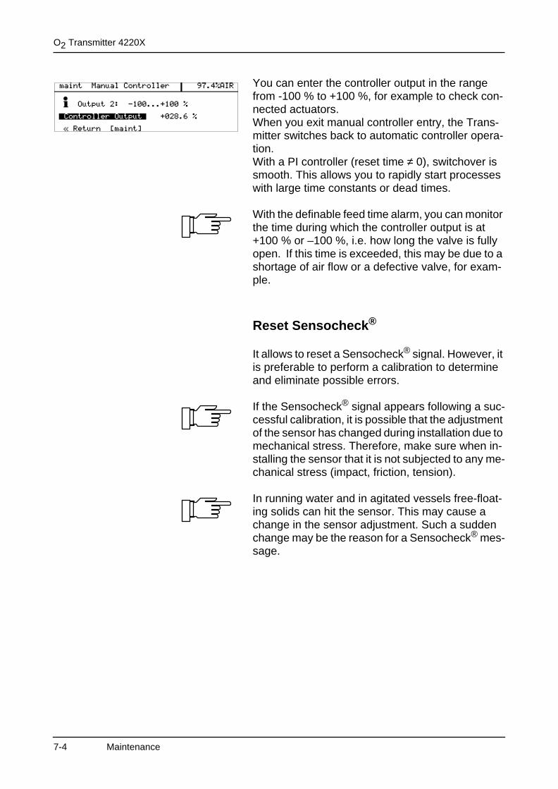
O2 Transmitter 4220X
You can enter the controller output in the range from -100 % to +100 %, for example to check con-nected actuators.When you exit manual controller entry, the Trans-mitter switches back to automatic controller opera-tion.With a PI controller (reset time ≠ 0), switchover is smooth. This allows you to rapidly start processes with large time constants or dead times.
With the definable feed time alarm, you can monitor the time during which the controller output is at +100 % or –100 %, i.e. how long the valve is fully open. If this time is exceeded, this may be due to a shortage of air flow or a defective valve, for exam-ple.
Reset Sensocheck®
It allows to reset a Sensocheck® signal. However, it is preferable to perform a calibration to determine and eliminate possible errors.
If the Sensocheck® signal appears following a suc-cessful calibration, it is possible that the adjustment of the sensor has changed during installation due to mechanical stress. Therefore, make sure when in-stalling the sensor that it is not subjected to any me-chanical stress (impact, friction, tension).
In running water and in agitated vessels free-float-ing solids can hit the sensor. This may cause a change in the sensor adjustment. Such a sudden change may be the reason for a Sensocheck® mes-sage.
7-4 Maintenance
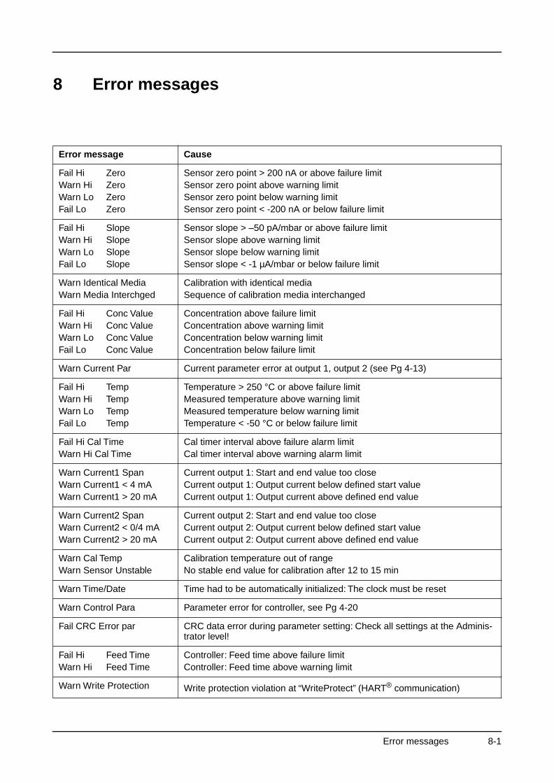
8 Error messages
Error message Cause
Fail Hi ZeroWarn Hi ZeroWarn Lo ZeroFail Lo Zero
Sensor zero point > 200 nA or above failure limitSensor zero point above warning limitSensor zero point below warning limitSensor zero point < -200 nA or below failure limit
Fail Hi SlopeWarn Hi SlopeWarn Lo SlopeFail Lo Slope
Sensor slope > –50 pA/mbar or above failure limitSensor slope above warning limitSensor slope below warning limitSensor slope < -1 µA/mbar or below failure limit
Warn Identical MediaWarn Media Interchged
Calibration with identical mediaSequence of calibration media interchanged
Fail Hi Conc ValueWarn Hi Conc ValueWarn Lo Conc ValueFail Lo Conc Value
Concentration above failure limitConcentration above warning limitConcentration below warning limitConcentration below failure limit
Warn Current Par Current parameter error at output 1, output 2 (see Pg 4-13)
Fail Hi TempWarn Hi TempWarn Lo TempFail Lo Temp
Temperature > 250 °C or above failure limitMeasured temperature above warning limitMeasured temperature below warning limitTemperature < -50 °C or below failure limit
Fail Hi Cal TimeWarn Hi Cal Time
Cal timer interval above failure alarm limitCal timer interval above warning alarm limit
Warn Current1 SpanWarn Current1 < 4 mAWarn Current1 > 20 mA
Current output 1: Start and end value too closeCurrent output 1: Output current below defined start valueCurrent output 1: Output current above defined end value
Warn Current2 SpanWarn Current2 < 0/4 mAWarn Current2 > 20 mA
Current output 2: Start and end value too closeCurrent output 2: Output current below defined start valueCurrent output 2: Output current above defined end value
Warn Cal TempWarn Sensor Unstable
Calibration temperature out of rangeNo stable end value for calibration after 12 to 15 min
Warn Time/Date Time had to be automatically initialized: The clock must be reset
Warn Control Para Parameter error for controller, see Pg 4-20
Fail CRC Error par CRC data error during parameter setting: Check all settings at the Adminis-trator level!
Fail Hi Feed TimeWarn Hi Feed Time
Controller: Feed time above failure limitController: Feed time above warning limit
Warn Write Protection Write protection violation at “WriteProtect” (HART® communication)
Error messages 8-1
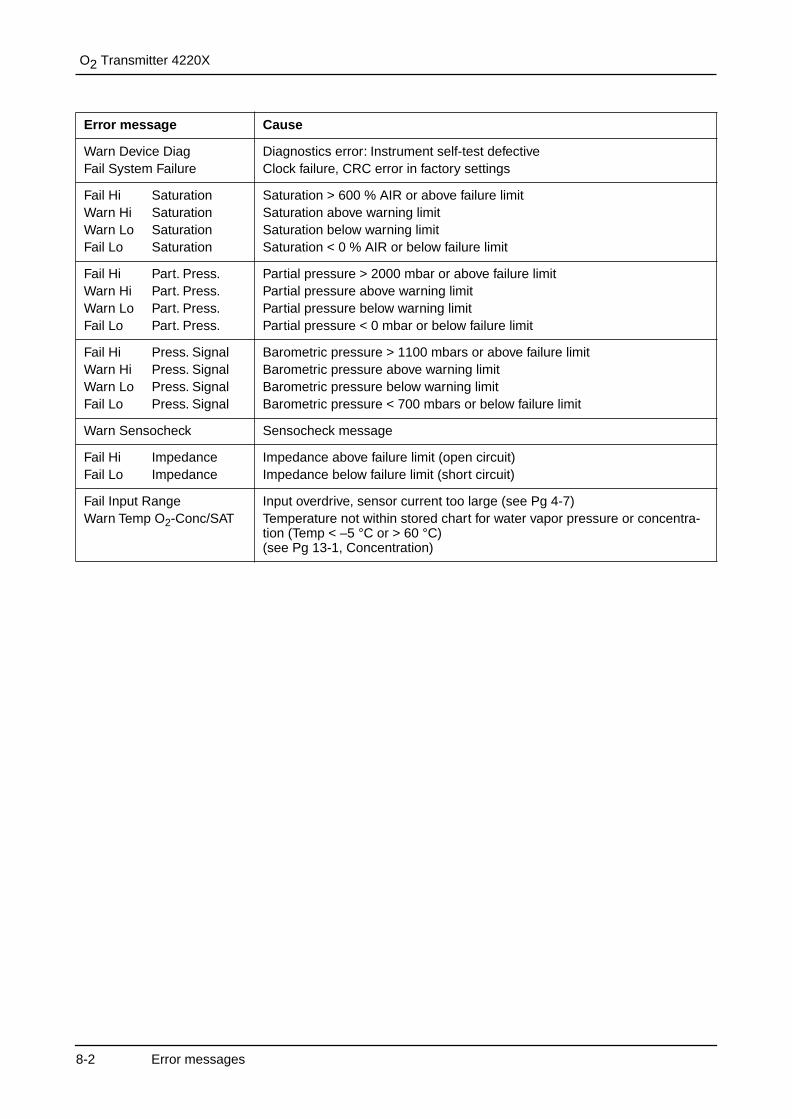
O2 Transmitter 4220X
Warn Device DiagFail System Failure
Diagnostics error: Instrument self-test defectiveClock failure, CRC error in factory settings
Fail Hi SaturationWarn Hi SaturationWarn Lo SaturationFail Lo Saturation
Saturation > 600 % AIR or above failure limitSaturation above warning limitSaturation below warning limitSaturation < 0 % AIR or below failure limit
Fail Hi Part. Press.Warn Hi Part. Press.Warn Lo Part. Press.Fail Lo Part. Press.
Partial pressure > 2000 mbar or above failure limitPartial pressure above warning limitPartial pressure below warning limitPartial pressure < 0 mbar or below failure limit
Fail Hi Press. SignalWarn Hi Press. SignalWarn Lo Press. SignalFail Lo Press. Signal
Barometric pressure > 1100 mbars or above failure limitBarometric pressure above warning limitBarometric pressure below warning limitBarometric pressure < 700 mbars or below failure limit
Warn Sensocheck Sensocheck message
Fail Hi ImpedanceFail Lo Impedance
Impedance above failure limit (open circuit)Impedance below failure limit (short circuit)
Fail Input RangeWarn Temp O2-Conc/SAT
Input overdrive, sensor current too large (see Pg 4-7)Temperature not within stored chart for water vapor pressure or concentra-tion (Temp < –5 °C or > 60 °C)(see Pg 13-1, Concentration)
Error message Cause
8-2 Error messages
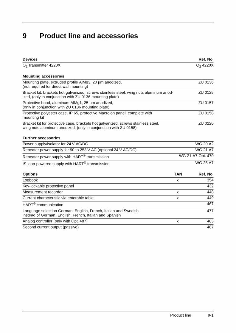
9 Product line and accessories
Devices Ref. No.
O2 Transmitter 4220X O2 4220X
Mounting accessories
Mounting plate, extruded profile AlMg3, 20 µm anodized,(not required for direct wall mounting)
ZU 0136
Bracket kit, brackets hot galvanized, screws stainless steel, wing nuts aluminum anod-ized, (only in conjunction with ZU 0136 mounting plate)
ZU 0125
Protective hood, aluminum AlMg1, 25 µm anodized,(only in conjunction with ZU 0136 mounting plate)
ZU 0157
Protective polyester case, IP 65, protective Macrolon panel, complete with mounting kit
ZU 0158
Bracket kit for protective case, brackets hot galvanized, screws stainless steel, wing nuts aluminum anodized, (only in conjunction with ZU 0158)
ZU 0220
Further accessories
Power supply/isolator for 24 V AC/DC WG 20 A2
Repeater power supply for 90 to 253 V AC (optional 24 V AC/DC) WG 21 A7
Repeater power supply with HART® transmission WG 21 A7 Opt. 470
IS loop-powered supply with HART® transmission WG 25 A7
Options TAN Ref. No.
Logbook x 354
Key-lockable protective panel 432
Measurement recorder x 448
Current characteristic via enterable table x 449
HART® communication 467
Language selection German, English, French, Italian and Swedishinstead of German, English, French, Italian and Spanish
477
Analog controller (only with Opt. 487) x 483
Second current output (passive) 487
Product line 9-1

O2 Transmitter 4220X
This page has been left empty for technical reasons.
9-2 Product line
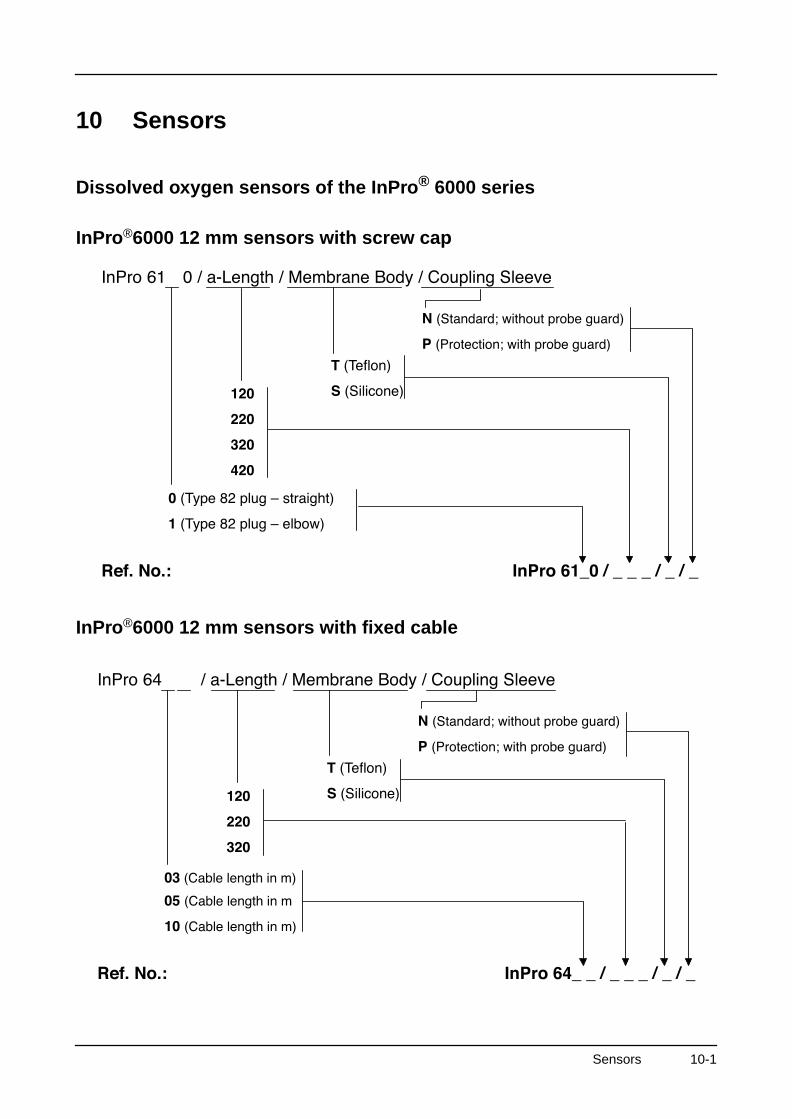
10 Sensors
Dissolved oxygen sensors of the InPro® 6000 series
InPro®6000 12 mm sensors with screw cap
InPro®6000 12 mm sensors with fixed cable
Sensors 10-1
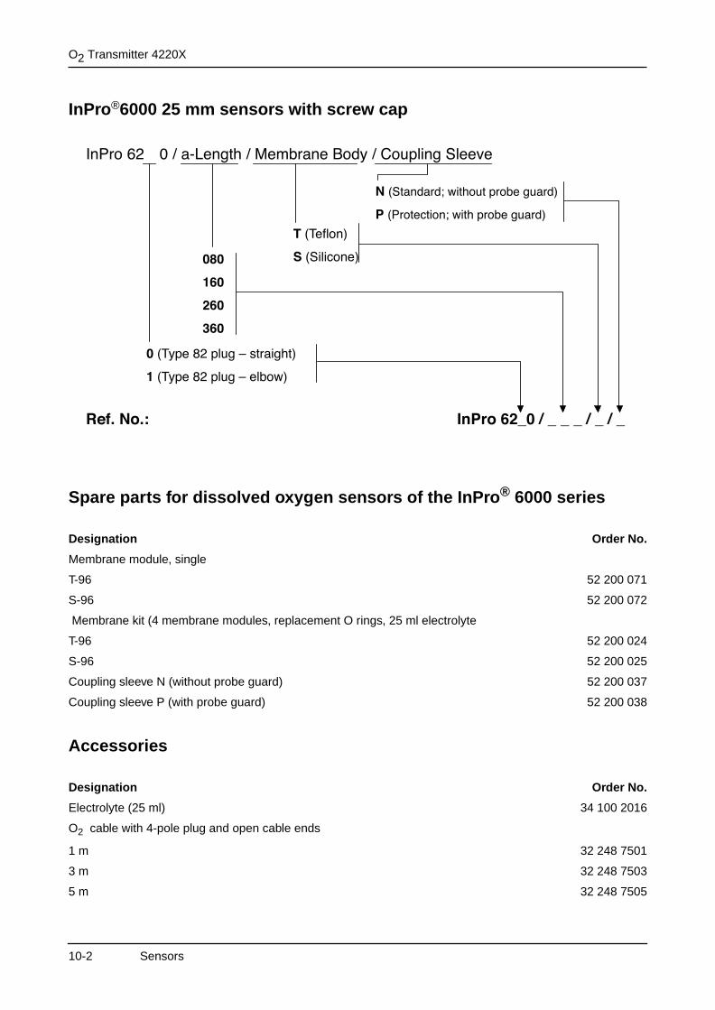
O2 Transmitter 4220X
InPro®6000 25 mm sensors with screw cap
Spare parts for dissolved oxygen sensors of the InPro® 6000 series
Accessories
Designation Order No.
Membrane module, single
T-96 52 200 071
S-96 52 200 072
Membrane kit (4 membrane modules, replacement O rings, 25 ml electrolyte
T-96 52 200 024
S-96 52 200 025
Coupling sleeve N (without probe guard) 52 200 037
Coupling sleeve P (with probe guard) 52 200 038
Designation Order No.
Electrolyte (25 ml) 34 100 2016
O2 cable with 4-pole plug and open cable ends
1 m 32 248 7501
3 m 32 248 7503
5 m 32 248 7505
10-2 Sensors

Sensor, 12 mm dia.
Sensor, 25 mm dia.
Installation length Order no. T type Order no. S type
a = 120 mm 34 100 3045 34 100 3049
a = 220 mm 34 100 3046 34 100 3050
a = 320 mm 34 100 3047 34 100 3051
a = 420 mm 34 100 3048 34 100 3052
Spare parts for sensor, 12 mm dia. Order no.
T membrane kit (replacement O rings, 4 membrane modules, 25 ml electrolyte) 34 100 2021
T membrane module, single 34 100 3040
S membrane kit (replacement O rings, 4 membrane modules, 25 ml electrolyte) 34 100 3041
S membrane module, single 34 100 2022
O2 electrolyte (25 ml) 34 100 2016
Installation length Order no.
a = 70 mm 32 275 6800
a = 150 mm 32 275 6801
a = 320 mm 32 275 6802
Spare parts for sensor, 25 mm dia. Order no.
Membrane kit (replacement O rings, 4 membrane modules, 25 ml electrolyte) 32 202 5114
Membrane module, single 32 204 8617
O2 electrolyte (25 ml) 34 100 2016
Accessories Order no.
O2 cable with 4-pole plug and open cable ends
1 m 32 248 7501
3 m 32 248 7503
5 m 32 248 7505
Sensors 10-3

O2 Transmitter 4220X
This page has been left empty for technical reasons.
10-4 Sensors
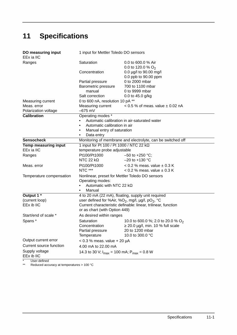
11 Specifications
DO measuring inputEEx ia IIC
1 input for Mettler Toledo DO sensors
Ranges Saturation
Concentration
Partial pressureBarometric pressure
manualSalt correction
0.0 to 600.0 % Air0.0 to 120.0 % O20.0 µg/l to 90.00 mg/l0.0 ppb to 90.00 ppm0 to 2000 mbar700 to 1100 mbar0 to 9999 mbar0.0 to 45.0 g/kg
Measuring currentMeas. errorPolarization voltage
0 to 600 nA, resolution 10 pA **Measuring current < 0.5 % of meas. value ± 0.02 nA–675 mV
Calibration Operating modes *• Automatic calibration in air-saturated water• Automatic calibration in air• Manual entry of saturation• Data entry
Sensocheck Monitoring of membrane and electrolyte, can be switched offTemp measuring inputEEx ia IIC
1 input for Pt 100 / Pt 1000 / NTC 22 kΩ temperature probe adjustable
Ranges
Meas. error
Temperature compensation
Pt100/Pt1000 –50 to +250 °C;NTC 22 kΩ –20 to +130 °CPt100/Pt1000 < 0.2 % meas. value ± 0.3 KNTC *** < 0.2 % meas. value ± 0.3 KNonlinear, preset for Mettler Toledo DO sensorsOperating modes:• Automatic with NTC 22 kΩ• Manual
Output 1 *(current loop)EEx ib IIC
Start/end of scale *Spans *
Output current errorCurrent source functionSupply voltageEEx ib IIC
4 to 20 mA (22 mA), floating, supply unit requireduser defined for %Air, %O2, mg/l, µg/l, pO2, °CCurrent characteristic definable: linear, trilinear, functionor as chart (with Option 449)As desired within rangesSaturation 10.0 to 600.0 %; 2.0 to 20.0 % O2Concentration ≥ 20.0 µg/l, min. 10 % full scalePartial pressure 20 to 1200 mbarTemperature 10.0 to 300.0 °C< 0.3 % meas. value + 20 µA4.00 mA to 22.00 mA14.3 to 30 V; Imax = 100 mA; Pmax = 0.8 W
* User-defined** Reduced accuracy at temperatures > 100 °C
Specifications 11-1
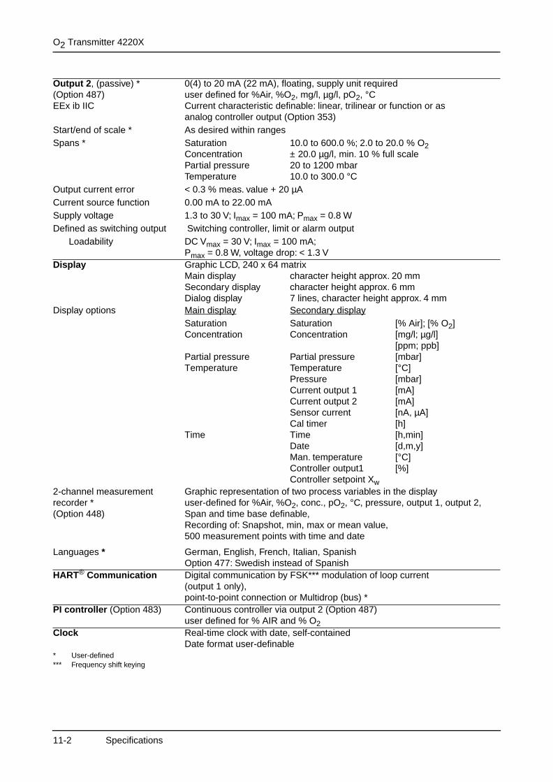
O2 Transmitter 4220X
Output 2, (passive) *(Option 487)EEx ib IIC
Start/end of scale *Spans *
Output current errorCurrent source functionSupply voltageDefined as switching output
Loadability
0(4) to 20 mA (22 mA), floating, supply unit requireduser defined for %Air, %O2, mg/l, µg/l, pO2, °CCurrent characteristic definable: linear, trilinear or function or as analog controller output (Option 353)As desired within rangesSaturation 10.0 to 600.0 %; 2.0 to 20.0 % O2Concentration ± 20.0 µg/l, min. 10 % full scalePartial pressure 20 to 1200 mbarTemperature 10.0 to 300.0 °C< 0.3 % meas. value + 20 µA0.00 mA to 22.00 mA1.3 to 30 V; Imax = 100 mA; Pmax = 0.8 W Switching controller, limit or alarm outputDC Vmax = 30 V; Imax = 100 mA;Pmax = 0.8 W, voltage drop: < 1.3 V
Display Graphic LCD, 240 x 64 matrixMain display character height approx. 20 mmSecondary display character height approx. 6 mmDialog display 7 lines, character height approx. 4 mm
Display options Main display Secondary displaySaturation Saturation [% Air]; [% O2]Concentration Concentration [mg/l; µg/l]
[ppm; ppb]Partial pressure Partial pressure [mbar]Temperature Temperature [°C]
Pressure [mbar]Current output 1 [mA]Current output 2 [mA]Sensor current [nA, µA]Cal timer [h]
Time Time [h,min]Date [d,m,y]Man. temperature [°C]Controller output1 [%]Controller setpoint Xw
2-channel measurement recorder *(Option 448)
Graphic representation of two process variables in the displayuser-defined for %Air, %O2, conc., pO2, °C, pressure, output 1, output 2,Span and time base definable,Recording of: Snapshot, min, max or mean value,500 measurement points with time and date
Languages * German, English, French, Italian, SpanishOption 477: Swedish instead of Spanish
HART® Communication Digital communication by FSK*** modulation of loop current(output 1 only),point-to-point connection or Multidrop (bus) *
PI controller (Option 483) Continuous controller via output 2 (Option 487)user defined for % AIR and % O2
Clock Real-time clock with date, self-containedDate format user-definable
* User-defined*** Frequency shift keying
11-2 Specifications
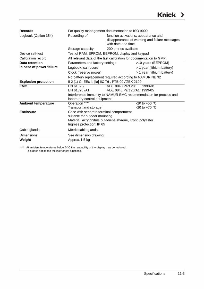
RecordsLogbook (Option 354)
Device self-testCalibration record
For quality management documentation to ISO 9000.Recording of function activations, appearance and
disappearance of warning and failure messages, with date and time
Storage capacity 200 entries availableTest of RAM, EPROM, EEPROM, display and keypadAll relevant data of the last calibration for documentation to GMP
Data retentionin case of power failure
Parameters and factory settings >10 years (EEPROM)Logbook, cal record > 1 year (lithium battery)Clock (reserve power) > 1 year (lithium battery)No battery replacement required according to NAMUR NE 32
Explosion protection II 2 (1) G EEx ib [ia] IIC T6 , PTB 00 ATEX 2190EMC EN 61326/ VDE 0843 Part 20: 1998-01
EN 61326 /A1 VDE 0843 Part 20/A1: 1999-05Interference immunity to NAMUR EMC recommendation for process and laboratory control equipment
Ambient temperature Operation **** -20 to +50 °CTransport and storage -20 to +70 °C
Enclosure
Cable glands
Dimensions
Case with separate terminal compartment,suitable for outdoor mountingMaterial: acrylonitrile butadiene styrene, Front: polyesterIngress protection: IP 65
Metric cable glands
See dimension drawingWeight Approx. 1.5 kg
**** At ambient temperatures below 0 °C the readability of the display may be reduced. This does not impair the instrument functions.
Specifications 11-3

O2 Transmitter 4220X
This page has been left empty for technical reasons.
11-4 Specifications
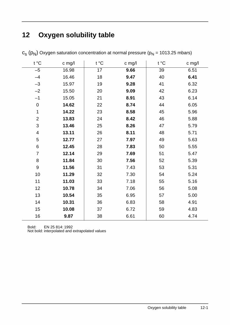
12 Oxygen solubility table
cs (pN) Oxygen saturation concentration at normal pressure (pN = 1013.25 mbars)
Bold: EN 25 814: 1992Not bold: interpolated and extrapolated values
t °C c mg/l t °C c mg/l t °C c mg/l
–5 16.98 17 9.66 39 6.51
–4 16.46 18 9.47 40 6.41
–3 15.97 19 9.28 41 6.32
–2 15.50 20 9.09 42 6.23
–1 15.05 21 8.91 43 6.14
0 14.62 22 8.74 44 6.05
1 14.22 23 8.58 45 5.96
2 13.83 24 8.42 46 5.88
3 13.46 25 8.26 47 5.79
4 13.11 26 8.11 48 5.71
5 12.77 27 7.97 49 5.63
6 12.45 28 7.83 50 5.55
7 12.14 29 7.69 51 5.47
8 11.84 30 7.56 52 5.39
9 11.56 31 7.43 53 5.31
10 11.29 32 7.30 54 5.24
11 11.03 33 7.18 55 5.16
12 10.78 34 7.06 56 5.08
13 10.54 35 6.95 57 5.00
14 10.31 36 6.83 58 4.91
15 10.08 37 6.72 59 4.83
16 9.87 38 6.61 60 4.74
Oxygen solubility table 12-1

O2 Transmitter 4220X
This page has been left empty for technical reasons.
12-2 Oxygen solubility tables
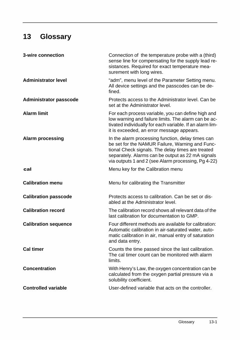
13 Glossary
3-wire connection Connection of the temperature probe with a (third) sense line for compensating for the supply lead re-sistances. Required for exact temperature mea-surement with long wires.
Administrator level “adm”, menu level of the Parameter Setting menu. All device settings and the passcodes can be de-fined.
Administrator passcode Protects access to the Administrator level. Can be set at the Administrator level.
Alarm limit For each process variable, you can define high and low warning and failure limits. The alarm can be ac-tivated individually for each variable. If an alarm lim-it is exceeded, an error message appears.
Alarm processing In the alarm processing function, delay times can be set for the NAMUR Failure, Warning and Func-tional Check signals. The delay times are treated separately. Alarms can be output as 22 mA signals via outputs 1 and 2 (see Alarm processing, Pg 4-22)
Menu key for the Calibration menu
Calibration menu Menu for calibrating the Transmitter
Calibration passcode Protects access to calibration. Can be set or dis-abled at the Administrator level.
Calibration record The calibration record shows all relevant data of the last calibration for documentation to GMP.
Calibration sequence Four different methods are available for calibration: Automatic calibration in air-saturated water, auto-matic calibration in air, manual entry of saturation and data entry.
Cal timer Counts the time passed since the last calibration. The cal timer count can be monitored with alarm limits.
Concentration With Henry’s Law, the oxygen concentration can be calculated from the oxygen partial pressure via a solubility coefficient.
Controlled variable User-defined variable that acts on the controller.
Glossary 13-1
O2 Transmitter 4220X
Cursor keys and , serve to select entry positions or digits during number entry.
Delay User-defined time until the NAMUR signals “Warn-ing” and “Failure” react to an alarm message and an off-delay of the NAMUR signal “Functional check”.
Menu key for the Diagnostics menu
Diagnostics menu Display of all relevant information on the device sta-tus.
DO sensor Dissolved oxygen sensor – O2-sensitive sensor
Key for confirming entries
Failure Failure is a NAMUR signal. The limits are set in the Alarm Settings menu. Failure means that the equipment no longer oper-ates properly or that a process parameter has reached a critical value.
Feed time alarm Monitors the time during which the controller output is at 100 %.
First calibration During First Calibration, the sensor data are stored as reference values for sensor statistics.
Functional check Functional check is a NAMUR signal. This signal is active during parameter setting, calibration and maintenance (see Alarm processing, Pg 4-22).
GMP Good Manufacturing Practice: Rules for perfor-mance and documentation of measurements.
HART® Digital communication by superimposing digital sig-nals on the loop current.
Information display Information text for operator guidance or indication of device status. Marked with .
Interval Time from the start of one device test to the start of the next device test, user defined.
Language selection In the Parameter Setting menu, you can select the user interface language: The language can be se-lected without entering a passcode.
Limit contact Is controlled by a user-defiable process variable. The limit contact is activated if the measured value falls below or exceeds an alarm limit, depending on the user-defined effective direction.
i
13-2 Glossary
Logbook The logbook shows the last 200 events with date and time, e.g. calibrations, warning and failure mes-sages, power failure etc. This permits quality man-agement documentation to ISO 9000.
Main display Large measured-value display in the measuring mode. The displayed process variable can be de-fined. The process variable of the main display is shown in the menus in the upper right corner.
Menu key for the Maintenance menu
Maintenance menu The Maintenance menu provides all functions for sensor maintenance and adjustment of connected devices.
Maintenance passcode Protects access to Maintenance. Can be set or dis-abled at the Administrator level.
Manipulated variable Output variable of the controller, controls output 2.
Menu key. Pressing allows return to mea-suring mode from all other menus.
Measurement recorder Two-channel recorder for optical display of the pro-cess development on the system display. One pro-cess variable can be assigned to each channel.
Measuring mode When no menu function is activated, the Transmit-ter is in measuring mode. The selected measured value is displayed. You can always return to the measuring mode by pressing .
Menu Pressing a menu key ( , , or ), gives access to a menu from which you can
select the corresponding functions.
Menu level The menu is divided into several menu levels.
You can switch between the different levels by pressing the corresponding menu key or a cursor key or ).
Message list The message list shows the number of currently ac-tivated messages and the individual warning or fail-ure messages in plain text.
NAMUR German committee for measurement and control standards in the chemical industry
NAMUR signals Failure, warning and functional check are NAMUR signals. They can be assigned to outputs 1 and 2 as 22 mA signals. The limits for failure and warning are set in the Alarm Settings menu.
Glossary 13-3
O2 Transmitter 4220X
Operator level “opl”, menu level of the Parameter Setting menu. You can edit the device settings that have been en-abled at the Administrator level.
Operator passcode Protects access to the Operator level. Can be set or disabled at the Administrator level.
Oxygen concentration See Concentration
Oxygen partial pressure See Partial pressure
Oxygen saturation See Percent saturation
Menu key for the Parameter Setting menu
Parameter Setting menu The Parameter Setting menu is divided into three submenus: Viewing level (view), Operator level (opl) and Administrator level (adm)
Partial pressure Share of a gas to the total pressure of the gas mix-ture
Passcode protection Access to the Calibration, Maintenance, Operator and Administrator levels is protected by passcodes. The passcodes can be defined or disabled at the Administrator level.
Percent saturation Ratio (in percent) of the measured quantity of O2 to the highest possible quantity (saturation)
Polarization time Time after power-on of the Transmitter until the sensor delivers stable measured values (also see operating instructions of sensor)
Pulse suppression To increase immunity to interference, a disconnect-able input filter suppresses transient interference pulses while slow changes of the measured value are detected immediately.
Recorder See Measurement recorder
Scrolling key and : Keys for selecting menu lines or enter-ing numbers.
Secondary display Two small displays located below the main display in measuring mode. The process variables to be displayed can be selected using / and
/ .
Sensor slope Specified in pA/mbar
13-4 Glossary
Sensor statistics The sensor statistics provide the sensor data of the last three calibrations and the first calibration.
Slope See Sensor slope.
Tag number Can be defined to identify the Transmitter and can be displayed in the diag menu.For HART® transmission, the first 8 characters are used as “TAG”.
TAN Transaction number for later installation of software options.
Temperature compensation Correction of temperature dependence of mem-brane diffusion
Viewing level “view”, menu level of the Parameter Setting menu. Display of all device settings, however no editing possible.
Warning (maintenance required) Alarm message, means that the equipment is still operating properly but should be serviced, or that process parameters have reached a value requiring intervention.
Zero point Sensor signal which is output when measuring in an oxygen-free medium.
Glossary 13-5

O2 Transmitter 4220X
This page has been left empty for technical reasons.
13-6 Glossary

14 Index
3-way mixing valve, 4-19
3-wire connection, Explanation, 13-1
A
Accessories, 9-1
Administrator level, 4-2Explanation, 13-1
Administrator passcode, 4-28Explanation, 13-1
Alarm contact, 4-16
Alarm limit, Explanation, 13-1
Alarm processing, 4-22Explanation, 13-1
Alarm settings, 4-21
Assembly, 1-1
ATEX Certificate, XI
Automatic calibration, 5-4
B
Bracket kit, 1-1
C
Cal record, 6-1
Cal timer, 4-23Explanation, 13-1
cal, Explanation, 13-1
Calibration, 5-1Automatic, 5-4Data entry, 5-8Freeze output currents, 5-4, 5-7, 5-8Manual entry of saturation, 5-7
Monitoring functions, 5-1
Calibration menu, 5-2Explanation, 13-1
Calibration passcode, Explanation, 13-1
Calibration record, 6-1Explanation, 13-1
Calibration sequence, Explanation, 13-1
Calibration timer alarm, 4-21
Cleaning, 1-6
Clock, setting, 4-25
Concentration, Explanation, 13-1
Control beginning, 4-17
Control end, 4-17
Controlled variable, Explanation, 13-1
Controller, 4-16Control characteristic, 4-17Controlled variable, 4-16Controller output, 4-18Manual, 7-3Parameter setting, Error
messages, 4-20
Corner point, 4-18Bilinear output curve, 4-10Trilinear output curve, 4-10
Current outputFalling curve, 4-9Output curve, 4-9Settings
Error messages, 4-13Span, 4-9, 4-10, 4-11
Current output 1, 4-8
Current output 2, 4-14
Current source function, 7-2
Cursor key, Explanation, 13-2
Index 14-1
O2 Transmitter 4220X
D
Date format, 4-25
Declaration of Conformity, X
Delay, Explanation, 13-2
Device description, 6-3
Device diagnostics, 4-25, 6-4
diag, Explanation, 13-2
Diagnostics menu, Explanation, 13-2
Display, Viewing angle, 4-4
DO sensor, Explanation, 13-2
E
EC Declaration of Conformity, X
EC-Type-Examination Certificate, XI
Effective direction, 4-15
enter, Explanation, 13-2
Error messages, 8-1
F
Factory setting, reset to, 4-3
Failure, Explanation, 13-2
Feed time alarm, 4-20Explanation, 13-2
First calibration, 5-2Explanation, 13-2
Functional check, Explanation, 13-2
G
Glossary, 13-1
GMP, Explanation, 13-2
H
HART® communication, 4-23
Hysteresis, 4-15
I
Information display, Explanation, 13-2
Input filter, 4-4
Installation, 1-5
Interval, Explanation, 13-2
L
Language selection, 4-1, 13-2
Limit contacts, 4-15Effective direction, 4-15Explanation, 13-2Hysteresis, 4-15
Logbook, 6-3Explanation, 13-3
M
Main display, Explanation, 13-3
maint, Explanation, 13-3
Maintenance, 1-6
Maintenance menu, Explanation, 13-3
Maintenance passcode, Explanation, 13-3
Manipulated variable, Explanation, 13-3
Marker setting, 4-2
meas, Explanation, 13-3
Measurement display, 4-3
Measurement point maintenance, 7-1
Measurement recorder, 4-26Average, 4-27Explanation, 13-3
14-2 Index
Max Value, 4-27Min Value, 4-27Snapshot, 4-27
Measuring mode, 3-2Explanation, 13-3
Memory test, 4-25
Menu level, Explanation, 13-3
Menu operation, 3-6Keypad assignment, 3-7
Menu structure, 3-5
Menu, Explanation, 13-3
Message list, 6-1, 7-2Explanation, 13-3
Mounting plate, 1-1
N
NAMUR signals, 4-22Explanation, 13-3
NAMUR, Explanation, 13-3
Neutral zone, 4-18
Note, 4-25
O
One-point calibration, 5-3
Operator level, 4-2Explanation, 13-2
Operator passcode, Explanation, 13-4
Option release, 4-29
Options, 9-1
Output 2, 4-14Alarm contact, 4-16Typical wiring, 2-6Wash contact, 4-20
Output curveBilinear, 4-10Function, 4-11
Linear, 4-9Logarithmic, 4-11Trilinear, 4-10User-defined chart, 4-12
Oxygen concentration alarm, 4-21
Oxygen concentration, Explanation, 13-4
Oxygen partial pressure alarm, 4-21
Oxygen saturation (referred to air)Explanation, 13-3
Oxygen saturation alarm, 4-21
Oxygen solubility table, 12-1
P
Package contents, VII
par, Explanation, 13-4
Parameter settingAdministrator level, 4-2
Marker setting, 4-2Factory setting, 4-3Language selection, 4-1Operator level, 4-2Viewing level, 4-2
Parameter Setting menu, Explanation, 13-4
Partial pressure, Explanation, 13-4
Passcode entry, 4-27
Passcode protection, Explanation, 13-4
Passcode, factory set, 4-28
Percent saturation, Explanation, 13-4
Polarization time, Explanation, 13-4
Pressure alarm, 4-21
Pressure correction, 4-4
Product line, 9-1
Proper use, IX
Protective case, 1-1
Protective hood, 1-1
Index 14-3
O2 Transmitter 4220X
Pulse suppression, Explanation, 13-4
R
Recorder, 13-4
Reset time, 4-18
S
Safety information, VIII
Salt content, 4-5
Scrolling key, Explanation, 13-4
Secondary displayExplanation, 13-4Process variables, 4-3
Self test, 4-25
Sensocheck®, 4-7Reset, 7-4
Sensor data, Setting, 4-7
Sensor monitor, 7-2
Sensor slope, Explanation, 13-4
Sensor statistics, 6-2Explanation, 13-5
Sensormonitor, 7-2
Setpoint, 4-17
Slope, 13-5
Slope alarm, 4-21
Software retrofitting, 4-29
Solubility table, 12-1
Span, 4-9
Specifications, 11-1
Straightway valve, 4-19
T
Tag note, 4-25
Tag number, 4-25Explanation, 13-5
TAN, 4-29, 13-5
Temp probe adjustment, 7-3
Temperature alarm, 4-21
Temperature compensation, 2-5, 13-5Automatic, 4-6Manual, 4-6
Temperature detection, 2-5, 4-6
Terminal assignments, 2-3
Transaction number, 4-29
Two-point calibration, 5-3
U
User interface, 3-1
V
Viewing angle adjustment, 4-4
Viewing level, 4-2Explanation, 13-5
W
Warning, Explanation, 13-5
Wash contact, 4-20
Z
Zero point alarm, 4-21
Zero point, Explanation, 13-5
14-4 Index