Embed Size (px)
Citation preview

Oblique Detonation Wave Engine: Preliminary Design and Performance Prediction
A project present to The Faculty of the Department of Aerospace Engineering
San Jose State University
in partial fulfillment of the requirements for the degree Master of Science in Aerospace Engineering
By
Calvin Nguyen
April, 2018
approved by
Dr. P. Papadopoulos Faculty Advisor

ABSTRACT
The content of this report will be lay the groundwork via a literature review of the research
performed on oblique detonation wave engines. The motivation, overall research goal, and
methodology will also be outlined. The second chapter will cover the preliminary design process
of the combustion section. The supersonic compression inlet, fuel mixing, detonation process are
analyzed in 2 dimensions as a starting point in the high-level design of the ODWE.

Table of Contents List of Figures ............................................................................................................................................... vi Nomenclature ............................................................................................................................................... vii 1.1 Motivation ......................................................................................................................................... 1 1.2 Literature Review .............................................................................................................................. 1
1.2.1 Oblique Detonation Wave Engine Theory .................................................................................... 1 1.2.2 Engine Configuration .................................................................................................................... 2 1.2.3 Detonation Combustion Chemistry ............................................................................................... 5 1.2.4 Formation and Structure of Oblique and Conical Detonation Waves ........................................... 6 1.2.5 ODWE Design Challenges ............................................................................................................ 9
1.3 Project Proposal ................................................................................................................................. 9 1.4 Methodology ...................................................................................................................................... 9 2.1 Analysis Introduction ...................................................................................................................... 10 2.2 Conservation Equations ................................................................................................................... 10 2.3 Flow Variables ................................................................................................................................. 10 2.4 Design Parameters ........................................................................................................................... 14 2.5 Preliminary Combustor Design ....................................................................................................... 15 3.1 Preliminary Inlet Design .................................................................................................................. 16 3.2 Fuel Mixing Device ......................................................................................................................... 17 3.3 Nozzle & Specific Impulse .............................................................................................................. 18 4.1 Future Work ..................................................................................................................................... 19 References .................................................................................................................................................... 20
v

List of Figures Figure 1. Generalized Engine Configuration.. ................................................................................................ 1 Figure 2. Normal Detonation Wave ............................................................................................................... 1 Figure 3. Temperature ranges of dissociation and ionization of air. .............................................................. 2 Figure 4. MSC and ESC Schematics .............................................................................................................. 3 Figure 5. Fuel Specific Impulse and Overall Efficiency ................................................................................ 3 Figure 6. Injector arrays on opposing duct walls ............................................................................................ 4 Figure 7. Oblique Detonation Wave Combustion .......................................................................................... 4 Figure 8. Truncated Plug Nozzle .................................................................................................................... 5 Figure 9. Rankine-Hugoniot curve and Rayleigh line. ................................................................................... 5 Figure 10. Typical Shock and Detonation Polars ........................................................................................... 7 Figure 11. Schematic of the formation process of an ODW ........................................................................... 7 Figure 12. Wave structure .............................................................................................................................. 8 Figure 13. Shock and detonation polars in semi-infinite wedge. .................................................................... 8 Figure 14. Detonation Initiation Modes ......................................................................................................... 9 Figure 15. Wave Angle ................................................................................................................................ 11 Figure 16. Density ratio ................................................................................................................................ 12 Figure 17. Velocity ratio .............................................................................................................................. 12 Figure 18. Pressure ratio ............................................................................................................................... 12 Figure 19. Temperature ratio ........................................................................................................................ 12 Figure 20. Locus of Chapman-Jouguet points for inlet flow at Mach 3. ...................................................... 13 Figure 21. Locus of Chapman-Jouguet points for inlet flow at Mach 5. ...................................................... 13 Figure 22. Locus of Chapman-Jouguet points for unlet flow at Mach 8 ...................................................... 13 Figure 23. Locus of Chapman-Jouguet points for inlet flow at Mach 10. .................................................... 13 Figure 24. Intake wave angle and ODW angle with respect to equivalence ratio , and Mach ..................... 15 Figure 25. Intake Flow Properties at exit ..................................................................................................... 16 Figure 26. Mach and Temperature Ratios at Fuel Mixing ............................................................................ 17 Figure 27. Specific Impulse vs Equivalence Ratio ....................................................................................... 18
vi

Nomenclature
= mixing efficiency c = mass fraction = mass flow rate
= density
p= pressure c = chord s = entropy = specific heat ratio = Stoichiometric coefficient r = reaction rate K = equilibrium constant q= velocity y= density ratio i,j,k = index T = temperature M= Mach number = Inlet deflection angle = ODW deflection angle = ODW angle angle
vii

1.1 Motivation
THE research in the field of air-breathing hypersonic propulsion systems is heavily directed towards oblique detonation wave engines (ODWE), rotary detonation engines (RDE), and pulse detonation engines (PDE). The
overall goal of this research is to accurately predict the performance of an ODWE with arbitrary hypersonic flow conditions. The concept of an ODWE for hypersonic aircraft was theorized in the 1950s and shown to have many
advantages relative to conventional air-breathing engines as well as rocket engines. The major advantages come from thermal efficiency and geometric simplicity, as discussed further in the following section. Hypersonic air-
breathing propulsion systems are of interest to the military as well as commercial applications such as single state to orbit (SSTO) vehicles.
1.2 Literature Review
The following literature discussed in this section starts from a high-level perspective analyzing the ODWE concept, basic two-dimensional compressible fluid mechanics, and combustion chemistry.
1.2.1 Oblique Detonation Wave Engine Theory
The basic concept of the ODWE is to use the vehicle geometry to induce a shock waves, which induces detonation of a fuel-oxidizer mixture, as seen in Figure 1. In most applications, the fuel injected is hydrogen.
Figure 1. Generalized Engine Configuration. Display of inlet (∞), fuel injection (1), point of complete
mixing (2), detonation (3), and chemical equilibrium (4), and exit (e) (Dunlap, 1958, p.452).
Figure 2. Normal Detonation Wave (Dunlap, 1958, p.452)
There are five major advantages to the ODWE, as listed below (Powers, 1994, p.4)
1. Simple supersonic inlet- deceleration to subsonic velocity is not required 2. Reduced total pressure losses 3. Shorter combustion chamber length – lighter structure 4. No ignition device required 5. Greater inlet velocities allowed
1

It is known that at temperatures of 2500K or greater, O2 molecules begin to dissociate, and at temperatures greater than 4000K, N2 molecules begin to dissociate (Anderson, 2000, p.459). To avoid reaching extreme temperatures that cause dissociation of air and combustion products, the flow throughout the engine is kept supersonic. Allowing the flow to remain supersonic, reduces the total pressure losses caused by excessive shock waves. If properly designed, the ODWE combustion process would take place rapidly over a very short region after the initiated shockwave, resulting in a much shorter and lighter engine (Dudebout, 1998, p.870). These factors are significant in the application of SSTO vehicles.
Figure 3. Temperature ranges of dissociation and ionization of air at 1atm (Anderson, 2000, p.459).
1.2.2 Engine Configuration The application of the ODWE in this paper will onboard a wave-rider vehicle, thus the geometry of the engine is easily adapted to a two-dimensional simplification of the geometry. The engine configuration will be broken down into 4 sections: inlet/diffuser, fuel injector/mixing area, combustion chamber, and nozzle. This section will go through of the main engine sections in order.
The inlet/diffuser designs for flight Mach numbers of 10-23 have been proven optimal by utilizing mixed supersonic compression (MSC) as opposed to fully internal (ISC) or external (ESC) compression designs. Studies by Dudebout (1998) have shown that an MSC inlet outperforms ESC inlets by increasing fuel specific impulse by over 20% (p.872). The figures below are shown to emphasize the inlet geometry and the flame holders should be disregarded, as they are not required in ODWEs.
2

Figure 4. MSC and ESC Schematics. External Compression (top), mixed external/internal compression
(bottom) (Alexander, 2006, p.2146)
Figure 5. Fuel Specific Impulse and Overall Efficiency (Doudebout, 1998, p.877)
The next station within the engine is the fuel injector. There have been many studies into hypersonic fuel injectors and whether the length scale required for sufficient mixing would be practical. A study by Alexander and Sislian (2006), looks deeper into the mixing process by utilizing the Window Allocatable Resolver for Propulsion code, which is a three-dimensional multispecies Favre-averaged Navier-Stokes numerical solver. Results of the study have proven that the mixing efficiencies of opposed wall injectors ranged from 0.459-0.681. The efficiencies range as the injector geometry is varied. The results of this study will be referenced often throughout the performance prediction research as a baseline for how to estimate mixing efficiencies vs length of the mixing section.
(1)
The mixing efficiency is measured by accounting for the decay in fuel mass fraction with downstream distance. However, this study quantifies the mixing at a streamwise plane of interest by defining the efficiency as the ratio of the oxygen that would burn in the plane to the mass flux of oxygen entering the engine.
3

Figure 6. Injector arrays on opposing duct walls (Alexander, 2006, p.2146)
Moving onto the oblique detonation wave combustor, the geometry is just as simple as the inlet, consisting of a wedge which induces ignition of the fuel-air mixture. Although the geometry is simple, the coupled combustion chemistry is complicated, with over 30 reactions which are occurring forwards and backwards (Jachimowski, 1988).
A study conducted by Valorani (2001) predicts ODWE performance with many assumptions regarding the mixing and combustion stages and states that the structure of the oblique detonation wave is calculated by “solving a set of ODEs which describe the flow of an inviscid reactive flow.” Most studies model the nonequilibrium combustion process using the reactive Euler equations, which assume of inviscid flow. The detailed kinetic model of the hydrogen-air system can be referenced from an analytical study of hydrogen-air reactions (Jachimowski, 1988). Without going into too much detail, the important material to be noted from these references are the reaction rates and equilibrium constants, which are discussed further in the following sections.
Figure 7. Oblique Detonation Wave Combustion (Valorani, 2001, p.214)
Following the combustion region is the supersonic nozzle. In this case of the ODWE, a converging-diverging nozzle is not applicable because the flow is supersonic throughout. To obtain optimal thrust levels, the nozzle exit should be chosen to adapt the exit flow to atmospheric pressure. A bell nozzle could be used, but for optimal efficiency, an altitude compensating truncated plug nozzle is used, as in reference (Valorani, 2001, p.215). In this study the plug surface is obtained by extending a line with the same angle as the detonation inducing wedge. The nozzle is truncated at 40% to reduce the overall length.
4

Figure 8. Truncated Plug Nozzle (Valorani, 2001, p.214)
1.2.3 Detonation Combustion Chemistry
The first step in understanding the combustion model was to start with the study of deflagration waves as opposed to detonation waves and how they are categorized. Equation (2), plotted for different mass fluxes is called the Rayleigh line, and its derivation can be found in reference (KTH, 2013). By plotting the Rankin-Hugoniot curve and Rayleigh line together gives insight into where a solution can be found that satisfies the conservation of mass, momentum and energy. In equation (3), the subscripts 1 and 2 Indica before and after the detonation wave.
(2)
(3)
In Figure 9, the Rankine-Hugoniot curve is plotted with a solid line, representing a nonzero heat addition value. The Hugoniot shock curve represents a zero heat addition case. The point (1,1) represent the inlet conditions. From equation (2), the slope of the Rayleigh line is always negative, thus the region V is not a valid solution. The different regions, based on the pressure change over the wave and separated by the upper and lower Chapman-Jouguet points, are called strong detonation (region I), weak detonation (II), weak deflagration (III) and strong deflagration (IV) (KTH, 2013, p.31).
Figure 9. Rankine-Hugoniot curve and Rayleigh line. Straight lines are Rayleigh lines for different mass fluxes. The dash-dot curve is the shock Hugoniot curve (KTH, 2013, p.31).
5

The chemical reaction rates are important factors to accurately model the combustion process. The basic governing equations of the chemical kinetic model can be found in references (Anderson, 2000, p.488).
(4)
(5)
(6)
(7) In order to model the fluid dynamics, these equations from the chemical kinetic model are coupled with a reactive flow model. The reactive flows can be adequately described by the reactive Euler equations and a set of rate equations for the production and consumption of chemical species (Valorani, 2001).
(8)
Regarding the equations above, the thermodynamic state of the mixture can be defined by two thermodynamics state variables. It is logical to use density and enthalpy; however, it is also suitable to use the logarithm of pressure, denoted as P, and entropy. The source terms in the reactive flow model equations are derived in reference (Shapiro, 1987).
1.2.4 Formation and Structure of Oblique and Conical Detonation Waves As a preliminary study, using a NASA Chemical Equilibrium with Applications code is adequate to model the high-level combustion, but to initiate the detonation wave takes more finesse. There have been many studies conducted researching the required conditions for a Chapman-Jouguet (CJ) detonation to occur in the chamber. Sosa and Ahmed (Sosa, 2017), have outlined the concept and design of a combustor to study the stabilization of normal and oblique detonation waves. This study theorizes an experimental setup capable of generating the conditions to match the CJ velocities to maintain a stable detonation wave. Equation (9) assumes a one-dimensional analysis with constant specific heats as a foundation to calculate the required CJ velocity.
(9)
6

The simplest way to solve the upstream and downstream conditions of the ODW is to assume the oblique shock and reaction zone are confined to an infinitely thin region. Solutions to the Rankine-Hugoniot are represented by polars that show detonation wave angles and their corresponding deflection angle (Verreault, 2012).
Figure 10. Typical Shock and Detonation Polars (Verreault, 2016, p.1767)
Based on analysis by Pratt et al. (1991), the deflection angle must be in the range < < ℎ for the ODW to be stabilized. This case would result in either a CJ or weak overdriven ODW. The formation of the detonation was studied by Li et al. (1994) with numerical simulations with detailed combustion chemistry. The simulation results revealed the thermally neutral induction zone as well as where the combustion reaction is taking place. The reaction sends compression waves toward the shock wave and increase its strength. The compression waves sharply decreased the induction length and marked the onset of the detonation wave (Verreault, 2012, p.1767).
Figure 11. Schematic of the formation process of an ODW (Verreault, 2012, p.1767)
7

Another study, conducted by Ghorbanian and Sterling (1996) and Verreault (2012), focused on a scenario in which the ODW would take place along two ramps of angles independent from one another. The first ramp would be the exact length of the induction zone. This study suggested additional requirements to obtain a steady detonation wave. Referring to regions shown in Figure 12, the two additional requirements are stated below.
1. Mach number in region 2 greater than the CJ Mach number 2. Pressure-matching of regions 3 and 4
It was concluded that the existence of a steady ODW was only possible if 0 < < , where < , < ℎ . Figure 12 shows a special
case of the semi-infinite wedge in which = .
The shock and detonation polars from Figure 13 can be used accordingly depending on the configuration of the engine. Waverider designs will be properly modeled using the semi-infinite wedge configuration.
Figure 12. Wave structure (Ghorbanian & Sterling, 1996, p.1768)
Figure 13. Shock and detonation polars in semi-infinite wedge and axisymmetric configurations (Verreault, 2012, p.1769).
8

1.2.5 ODWE Design Challenges
Studies have shown how aerodynamics and mixture thermodynamics affect the initiating detonation of normal detonation waves. The stability of detonation waves has been mentioned in the preceding section. Achieving a stable ODW is difficult with variable inlet conditions and more studies on the detonation wave structure and instability need to be performed. Most studies have simplified the chemical kinetics with a one-step irreversible model (Wang et al., 2015). A more accurate modeling is studied in hydrogen-air combustion analysis (Jachimowski, 1988). This kinetic model accounts for over 30 reactions taking place in the forward and backward directions involving hundreds of species.
As mentioned throughout the literature review, almost all studies utilize a flow model omitting heat transfer and viscous effects, apart from the study by Alexander (2006), which uses the full Navier-Stokes equations to simulate mixing performance.
A study by Li et al. (2016) studies the different types of initiating shock waves. Figure 14, shown below, gives a visual aid to inspect the different detonation initiation modes, which depend on the inlet Mach number.
Figure 14. Detonation initiation modes (Li et al., 2016, p.4)
Most studies mentioned thus far have been theoretical. Gong et al. (2017) performed an experimental study to investigate the asymmetric structure of multiple wave systems and the instabilities that occur within them more than once.
1.3 Project Proposal
There have been many extensive theoretical analyses of ODWE components. The overall research goal will be to accurately predict engine performance considering the inlet, fuel injectors, combustor, and nozzle. This analysis will be an engineering level trade study of the ODWE components. An accurate prediction without the direct use of extensive numerical simulations will simplify the preliminary design of oblique detonation wave engines.
1.4 Methodology
The research in this paper will consist of three main parts. The first will be a high-level modeling of the detonation wave behavior. This part will be written in MATLAB and will initially make many assumptions such as two-dimensional flow from stage to stage within the engine. The second part will go into greater depth to analyze the air intake section and nozzle to calculate an overall specific impulse approximation.
9

2.1 Analysis Introduction The detonation wave is an exothermal wave moving supersonically throughout the mixture of the reacting gases. The content of this chapter heavily references the study conducted by Gross (1963). This study makes several assumptions to simplify the general two-dimensional problem even further. The governing equations introduced in the following section assume that the wave thickness is infinitely small and the flow across the wave is treated as a discontinuity with heat addition.
2.2 Conservation Equations
The following equations represent the steady flow across the detonation wave. Conservation of mass across the wave is expressed by
1 1 sin = 2 2 sin( − )
The conservation of momentum in the normal and tangential direction are expressed by
1 = 1 1 2 sin2 = 2 + 2 2 2 sin2( − ) 1 1 2 sin cos = 2 2 2 sin( − ) cos( − )
The energy equation is expressed simply as flow with heat added
2 2
+ 1
+ = + 2
1 1
2 2 2
2
The equation of state is simply represented as
=
The density ratio can be solved analytically in terms of the initial Mach number, wave angle, and heat added by assuming that 1 = 2 .
2 1
{[1 + 2 sin2 ]2 − ( + 1) 2 sin2 [2 + (
) + ( − 1) 2 sin2
]} 2
1
1 1 1
= 1 + 1 sin2 ±
1 ( + 1) 2 sin2
2 1
When heat addition is equal to zero, the density ratio is simply the density jump across an oblique shock. The equation above is also analogous to normal detonation theory in which there is a real solution for both a weak and strong detonation. The singular solution corresponds to the well-known Chapman-Jouget condition. Oblique detonation waves should represent the Chapman-Jouguet situation (Gross, 1963, p.1226). This situation occurs when the downstream velocity component normal to the wave is sonic. The density ratio equation is simplified as shown below.
1
=
1 + 1 2 sin2
( + 1) 2 sin2 2 1
2.3 Flow Variables The remaining flow variables are solved in terms of the initial flow conditions and the density ratio.
1 2 = {1 − sin 2 [1 − ( 1 ) 2 ]} 2 1 2
10

2 = 1 + 2 sin2 [1 − ( 1 )]
1
1 2
2 = ( 2 ) ( 1 ) 1 1 2
= − cos−1[( 1 / 2 ) ] 1
2 = ( 2 ) ( 1 ) 2 1 1 2
Figures 15-18 express the flow variables with respect to the deflection angle. All plots are generated assuming
= = 6 to get a general understanding of detonation flow properties. The Damkohler parameter , is 1
an important design parameter.
Figure 15. Wave Angle ( = )
11

Figure 16. Density ratio ( = ) Figure 18. Pressure ratio ( = )
Figure 17. Velocity ratio ( = ) Figure 19. Temperature ratio ( = )
All figures were generated with a MATLAB script and can be altered to display any Mach number range and Damkohler parameter. Figures 15-19 express the detonation wave behavior in terms of Damkohler parameter, deflection angle, and wave angle for a constant inlet Mach number.
12

Figure 20. Locus of Chapman-Jouguet points for inlet flow at Mach 3. Figure 21. Locus of Chapman-Jouguet points for inlet flow at Mach 5.
Figure 22. Locus of Chapman-Jouguet points for unlet flow at Mach 8 Figure 23. Locus of Chapman-Jouguet points for inlet flow at Mach 10.
13

2.4 Design Parameters
The analytical solutions to the equations in the previous section are used to make an initial approximation of the combustion process by assuming a shockwave with an instantaneous increase in energy. Initial flow conditions are determined by assuming an atmospheric pressure of 90kPa ( ∞ ). The rest of the freestream flow conditions ( ∞ , ∞ , ∞, . ) can be determined by assuming a specific altitude and freestream Mach number. In the following calculations, an altitude of 21km is assumed to keep consistent with the reference (Powers, 1994) for the purpose of benchmarking.
It is important to note that all analytical data generated thus far are only for general reference. A key parameter in the preliminary design is the mixture ratio, often called the equivalence ratio, and fuel mass fraction are expressed as
= = /( + )
The fuel mass fraction can then be expressed in terms of the mixture ratio.
= (1 + −1)−1
From the assumption that the combustible mixture is a perfect mixture of air and hydrogen, the mass fractions can be solved for the combustion chamber inlet. The following equations express the specific heats at constant pressure and volume.
= ∑ , = , + , (1 − ) = ∑ , = , + , (1 − )
= , + , (1 − ) , + , (1 − )
The specific heat of air and hydrogen are calculated with the empirical equation found in reference (Borgnakke, 2017, p.671) for ideal gases within the 250-1200K. Because of the complexity of the mixing phase, the static temperature and pressure of both air and fuel just upstream of the ODW are approximated to be 850K and 0.5-1.5atm. The upstream temperature must also guarantee that the post-wave temperature if greater than the required temperature to automatically ignite in the chamber.
= + 1 + 2 2 + 3 3
It can be observed, however, that the fuel mixture ratio has a negligible effect on the equivalent specific heat ratio upstream of the ODW. As a result, the same flow variable plots can be used while varying the mixture ratio. From Jachimowski (1988), it can be shown that the optimal Mach number at the intake exit is 0.5 ∞ and the wave angles of the mixed internal/external supersonic compression of the intake have negligible effect on the mixture ratio, as seen in figure 10.
14

Figure 24. Intake wave angle , and ODW angle with respect to equivalence ratio , and freestream Mach number (Valorani, 2000, p.218)
2.5 Preliminary Combustor Design
The preceding technical aspect of design parameters leading up to this point are presented as guidelines to follow during the preliminary design phase of an ODWE. This chapter focused primarily on the combustion section and the detonation wave mechanics in a simplified manner to explore the wave behavior while varying design parameters. The main design parameters are freestream Mach number ∞ , fuel mixture ratio , and Damkohler parameter . Figures 20-23 show the relationship between wave angle and wedge deflection angle for varying Domkohler parameter values. Upon determining the freestream Mach number and range of heat addition relevant to the design requirements, these figures should be generated. It is important to note that the wave angles of the MSC intake must be solved (numerically) with the given and . The next step in the design process is to take note of the ODW angle and deflection angle corresponding to the CJ detonation point. From here figures 15-19 can be regenerated with a better approximation of the specific heat ratio, however it may not be necessary in the preliminary design phase. These figures can be used to approximate the required flow properties upstream and downstream of the ODW, which are used in the numerical solving of the intake and nozzle for optimal performance. Upon reviewing literature on the topic of ODWE propulsion systems, a methodology using simplified continuity equations were used to model the combustion section of the engine. There are many design parameters to consider, but for the analysis thus far, detonation parameters are reduced to the mixing ratio, Damkohler parameter, and intake Mach number. The preliminary analysis steps to obtain overall performance are completed. The following calculations required will be to model the MSC inlet and nozzle.
15

3.1 Preliminary Inlet Design This chapter will go into detail on the analysis of the air intake and fuel mixing section. Several assumptions are made to keep the modeling of the mixing device as simple as possible to gain high level insight to how the different design parameters affect performance. As mentioned previously, the inlet design will consist of both external and internal compression. The design parameters of the intake will be the upstream Mach number, wedge angles, and number of ramps at both the external and internal sections. To limit the parameters of the analysis, the number of ramps in each section will be equal and the wedge angles in each section are held constant from ramp to ramp. The analysis will assume 3 ramps with positive deflection angle and 3 ramps with equal and opposite deflection angles in the internal compression section to straighten out flow. The overall performance will be analyzed by varying inlet Mach number, ramp angles, Dankholer parameter, and fuel mixing ratio. The figures below represent flow behavior across an MSC inlet while varying the freestream Mach number as ramp deflection angles. Figure 25. Intake Flow Properties at exit (entrance to mixing device) with respect to freestream Mach and ramp deflection angle
16

3.2 Fuel Mixing Device At the exit of the intake is the start of the fuel mixing device. An accurate model of the mixing requires intensive CFD analysis which has many different design possibilities. The following analysis treats the mixing section as a black box in which the flow properties are slightly altered due to the injected fuel. The fuel is assumed to be injected at the same temperature as the static temperature of air at the intake exit. From the study by Valorani et al. (2001, p.217), “the static pressure ratio after and before mixing increases almost linearly with the equivalence ratio starting from a value of 1.2 at = 0.4 to 1.9 at 2.0.” This study uses numerical techniques to approximate the Mach number after mixing. This study is the baseline in which the mixing performance is calculated. The following analysis will use Mach ratios interpolated from the figures below generated by Valorani et al.
Figure 26. Mach and Temperature Ratios at Fuel Mixing
17
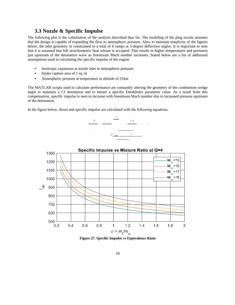
3.3 Nozzle & Specific Impulse The following plot is the culmination of the analysis described thus far. The modeling of the plug nozzle assumes that the design is capable of expanding the flow to atmospheric pressure. Also, to maintain simplicity of the figures below, the inlet geometry in constrained to a total of 6 ramps at 3-degree deflection angles. It is important to note that it is assumed that full stoichiometric heat release is accepted. This results in higher temperatures and pressures just upstream of the detonation wave as freestream Mach number increases. Stated below are a list of additional assumptions used in calculating the specific impulse of the engine.
• Isentropic expansion at nozzle inlet to atmospheric pressure • Intake capture area of 1 sq. m • Dynamics Pressure ( ∞ = 90 )
• Atmospheric pressure at temperature at altitude of 21km The MATLAB scripts used to calculate performance are constantly altering the geometry of the combustion wedge angle to maintain a CJ detonation and to ensure a specific Damkholer parameter value. As a result from this compensation, specific impulse is seen to increase with freestream Mach number due to increased pressure upstream of the detonation. In the figure below, thrust and specific impulse are calculated with the following equations.
2
−1
− 1
2
2
=
{( ) [1 + ] − 1}
− 1
2
= √ ∗ ℳ ∗
= − ∞ ∞
= ∞
Figure 27. Specific Impulse vs Equivalence Ratio
18

4.1 Future Work The analysis thus far has been completed at a high level to gain insight to the requirements to achieve a steady ODW within the combustion section of the engine. To achieve accurate results, intensive CFD must be performed. In future works, it would be beneficial to repeat this analysis with detailed numerical analysis enveloping performance with real mixing at supersonic speeds. It is known that over 30 chemical reaction are occurring and the detonation mechanics analysis makes several assumptions that would yield more accurate results with detailed chemistry modeled.
4.2 Conclusion In figure 27, it can be seen that specific impulse values are comparable to scramjet engines, however it is important to note that the freestream Mach numbers are much higher. As mentioned in the literature review, one main goal of the ODWE is to enable the use of a hybrid engine implemented in a SSTO vehicle. The ODWE would be the ideal form of propulsion within the upper-atmosphere where the static density is sufficient to support an air-breathing engine. It is seen throughout the analysis process that although the detonation chemistry and physical flow characteristics can be very difficult to model, several assumptions can be made to simplify the problem. Current research on the topic of ODWEs look to gain insight to achieve a steady ODW. The theoretical requirements and flow quantity limits are known but implementing them in CFD analyses are challenging. As mentioned in the section 3.3, the MATLAB scripts utilize a wedge angle compensator to ensure a specific heat addition value known as the Damkholer parameter. Further research could look into the feasibility of a physical compensator and the required control systems to maintain a steady ODW.
19
References Alexander, D. C., Sislian, J. P., & Parent, B. (2006). Hypervelocity Fuel/Air Mixing in Mixed-Compression Inlets of
Shcramjets. AIAA Journal,44(10), 2145-2155. doi:10.2514/1.12630 Anderson, J. D. (2006). Hypersonic and high-temperature gas dynamics. Reston: AIAA. Borgnakke, C., & Sonntag, R. E. (2017). Fundamentals of thermodynamics. Hoboken, NJ: John Wiley & Sons. Dudebout, R., Sislian, J. P., & Oppitz, R. (1998). Numerical Simulation of Hypersonic Shock-Induced Combustion
Ramjets. Journal of Propulsion and Power,14(6), 869-879. doi:10.2514/2.5368 Dunlap, R. (1958). A Preliminary Study of the Application of Steady-State Detonative Combustion to a
Reaction Engine. Journal of Jet Propulsion,28(7), 451-456. doi:10.2514/8.7347 Ghorbanian, K., & Sterling, J. D. (1996). Influence of formation processes on oblique detonation
wave stabilization. Journal of Propulsion and Power,12(3), 509-517. doi:10.2514/3.24064 Gong, J. S., Zhang, Y., Pan, H., Jia, B., Meng, H., & Lin, X. (2017). Experimental Investigation on Initiation of Oblique
Detonation Waves. 21st AIAA International Space Planes and Hypersonics Technologies Conference. doi:10.2514/6.2017-2350
Gross, R. A. (1963). Oblique Detonation Waves. AIAA Journal,1(5), 1225-1227. doi:10.2514/3.1777 Jachimowski, C. J. (1988). An analytical study of the hydrogen-air reaction mechanism with application to scramjet
combustion. Washington, D.C.: National Aeronautics and Space Administration, Scientific and Technical Information Division.
KTH Royal Institute of Technology in Stockholm “A combustion wave in a premixed gas, the Chapman-Jouguet Detonation Wave” (n.d.). Retrieved from https://www.mech.kth.se/courses/5C1219/Hand_out_PDF/SG2219_NT_Lecture%205%20HT10.pdf
Lee, H., Fan, W., & Xiao, Q. (2016). Numerical investigation of the initiation and propagation of oblique detonation waves in a confined combustion chamber. 52nd AIAA/SAE/ASEE Joint Propulsion Conference. doi:10.2514/6.2016-5108
Li, C., Kailasanath, K., & Oran, E. S. (1994). Detonation structures behind oblique shocks. Physics of Fluids,6(4), 1600-1611. doi:10.1063/1.868273
Migdal, D. (1971). Supersonic annular nozzles. 9th Aerospace Sciences Meeting. doi:10.2514/6.1971-43 Powers, J. M. (1994). Oblique Detonations: Theory and Propulsion Applications. ICASE/LaRC Interdisciplinary Series
in Science and Engineering Combustion in High-Speed Flows,345-371. doi:10.1007/978-94-011-1050-1_12 Pratt, D. T., Humphrey, J. W., & Glenn, D. E. (1991). Morphology of standing oblique detonation waves. Journal of
Propulsion and Power,7(5), 837-845. doi:10.2514/3.23399 Shapiro, A. H. (1987). The dynamics and thermodynamics of compressible fluid flow. Malabar, FL: R.E. Krieger. Sosa, J., & Ahmed, K. (2017). Design & Development of a Hypersonic Combustor for Oblique Detonation Wave
Stabilization. 55th AIAA Aerospace Sciences Meeting. doi:10.2514/6.2017-0371 Valorani, M., Giacinto, M. D., & Buongiorno, C. (2001). Performance prediction for oblique detonation wave
engines (odwe). Acta Astronautica,48(4), 211-228. doi:10.1016/s0094-5765(00)00161-2 Verreault, J., Higgins, A. J., & Stowe, R. A. (2012). Formation and Structure of Steady Oblique and Conical
Detonation Waves. AIAA Journal,50(8), 1766-1772. doi:10.2514/1.j051632 Wang, T., Zhang, Y., Teng, H., & Jiang, Z. (2015). Oblique Shock to Detonation Transition in Hydrogen-air
Mixtures. Procedia Engineering,126, 209-213. doi:10.1016/j.proeng.2015.11.222
20


![arXiv:2005.13391v1 [physics.flu-dyn] 27 May 2020 · 2020. 5. 28. · Ignition criteria and the e ect of boundary layers on wedge-stabilized oblique detonation waves Christian L. Bachmana,,](https://img.pdfslide.net/doc/110x75/60c34a9b89b2a158dc7bcc32/arxiv200513391v1-27-may-2020-2020-5-28-ignition-criteria-and-the-e-ect.jpg)