Embed Size (px)
Citation preview
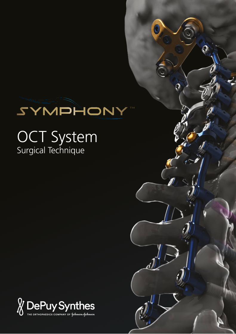
OCT SystemSurgical Technique
TM
Contents
SYMPHONY™ OCT System Surgical Technique DePuy Synthes 1
For MR information, please see Symphony IFU-0902-90-161.
Product Overview
Surgical Technique
Indications and Contraindications
Product Description 2
Preoperative Preparations 4
Surgical Technique 5
Optional Surgical Techniques
Reduction Screws 17
Cannulated and Percutaneous Technique 19
Compression and Distraction 26
Head to Head Cross Connectors 26
Rod to Rod Cross Connectors 29
Multipoint 30
C1 Drill Tap and Screw Guide 34
Lateral Offset Connectors 37
Parallel Connectors 37
Top Loading Connectors 38
Reduction Connectors 40
Axial Connectors 41
Cable Connectors 42
Laminar Hooks 43
Implant Removal Instructions 44
Compatibility 45
SYNAPSE™ OCT System Compatibility 46
Occipital Cervical Fusion
SYNAPSE OCT System – OC Fusion 48
MOUNTAINEER® OCT System – OC Fusion 64
Assembly Instructions 71
85
2 DePuy Synthes SYMPHONY™ OCT System Surgical Technique
Product Description
Introduction
The DePuy Synthes Spine SYMPHONY™ Occipito-Cervico-Thoracic (OCT) System is an enhanced set of instruments and implants, including polyaxial screws, 3.5 mm and 4.0 mm rods, compatible hooks, cross connectors, lateral offset connectors, and rod connectors designed for posterior stabilization of the upper spine. The implants provide the flexibility required to accommodate variations in patient anatomy.
The DePuy Synthes Spine SYMPHONY OCT System is compatible with occipital fusion components (plates, rods and clamps) from the SYNAPSE™ OCT System and the MOUNTAINEER® OCT Spinal System. Additionally, tapered rods and connectors are available to extend constructs to utilize both the DePuy Synthes Spine EXPEDIUM® and VIPER® Spine Systems.
SYMPHONY™ OCT System Surgical Technique DePuy Synthes 3
Preoperative Preparations
Preparation
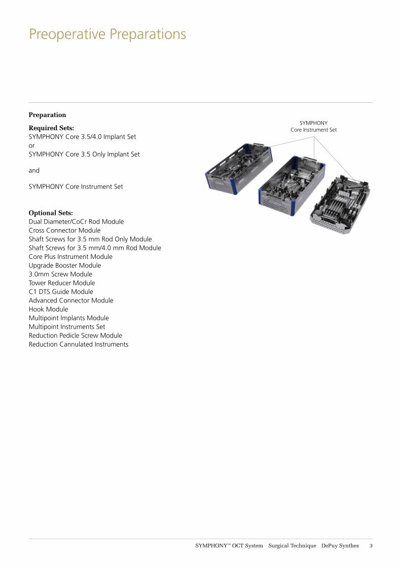
Required Sets:SYMPHONY Core 3.5/4.0 Implant SetorSYMPHONY Core 3.5 Only Implant Set
and
SYMPHONY Core Instrument Set
Optional Sets:Dual Diameter/CoCr Rod ModuleCross Connector ModuleShaft Screws for 3.5 mm Rod Only ModuleShaft Screws for 3.5 mm/4.0 mm Rod ModuleCore Plus Instrument ModuleUpgrade Booster Module3.0mm Screw ModuleTower Reducer ModuleC1 DTS Guide ModuleAdvanced Connector ModuleHook ModuleMultipoint Implants ModuleMultipoint Instruments SetReduction Pedicle Screw ModuleReduction Cannulated Instruments
SYMPHONY Core Instrument Set
4 DePuy Synthes SYMPHONY™ OCT System Surgical Technique
Preoperative Preparations
Preoperative Planning1ImagingIt is a prerequisite that, due to the anatomic variability of each patient, the surgeon has available the range of necessary images in order to plan the operation appropriately.
Use of cross sectional imaging (i.e., CT and/or MRI) for posterior cervical screw placement is recommended. The use of planar radiographs (or fluoroscopy) alone may not provide the necessary imaging to mitigate the risk of improper screw placement. In addition, use of intraoperative imaging should be considered to guide and/or verify device placement, as necessary.
2Assemble InstrumentsThe following instruments must be assembled prior to use:• Drill Guide, page 71• Polyaxial Screwdriver, page 75• AO Handles, page 77• Reducer Kerrison, page 79• Tower Reducer, page 81• C1 Alignment Sleeve, p. 84
3Patient PositioningPatient positioning is critical for cervical posterior fusion procedures. Place the patient on the operating table in the prone position with the patient’s head securely immobilized. Proper patient position should be confirmed via direct visualization and by radiographs prior to draping.
4 ApproachExpose the posterior bony elements sufficiently to allow placement of instrumentation as well as preferred graft material in and around the decorticated posterior elements.
SYMPHONY™ OCT System Surgical Technique DePuy Synthes 5
Surgical Technique
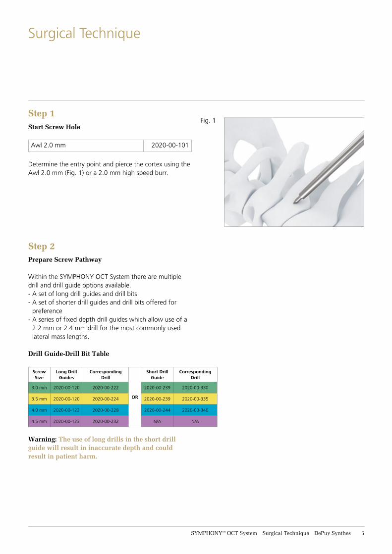
Step 1Start Screw Hole
Awl 2.0 mm 2020-00-101
Determine the entry point and pierce the cortex using the Awl 2.0 mm (Fig. 1) or a 2.0 mm high speed burr.
Step 2Prepare Screw Pathway
Within the SYMPHONY OCT System there are multiple drill and drill guide options available. - A set of long drill guides and drill bits - A set of shorter drill guides and drill bits offered for
preference- A series of fixed depth drill guides which allow use of a
2.2 mm or 2.4 mm drill for the most commonly used lateral mass lengths.
Drill Guide-Drill Bit Table
Screw Size
Long Drill Guides
Corresponding Drill
OR
Short Drill Guide
Corresponding Drill
3.0 mm 2020-00-120 2020-00-222 2020-00-239 2020-00-330
3.5 mm 2020-00-120 2020-00-224 2020-00-239 2020-00-335
4.0 mm 2020-00-123 2020-00-228 2020-00-244 2020-00-340
4.5 mm 2020-00-123 2020-00-232 N/A N/A
Warning: The use of long drills in the short drill guide will result in inaccurate depth and could result in patient harm.
Fig. 1
6 DePuy Synthes SYMPHONY™ OCT System Surgical Technique
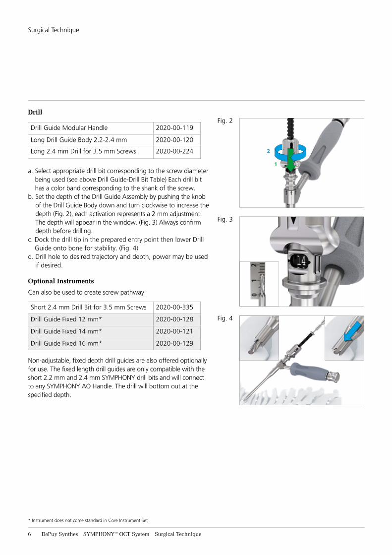
Drill
Drill Guide Modular Handle 2020-00-119
Long Drill Guide Body 2.2-2.4 mm 2020-00-120
Long 2.4 mm Drill for 3.5 mm Screws 2020-00-224
a. Select appropriate drill bit corresponding to the screw diameter being used (see above Drill Guide-Drill Bit Table) Each drill bit has a color band corresponding to the shank of the screw.
b. Set the depth of the Drill Guide Assembly by pushing the knob of the Drill Guide Body down and turn clockwise to increase the depth (Fig. 2), each activation represents a 2 mm adjustment. The depth will appear in the window. (Fig. 3) Always confirm depth before drilling.
c. Dock the drill tip in the prepared entry point then lower Drill Guide onto bone for stability. (Fig. 4)
d. Drill hole to desired trajectory and depth, power may be used if desired.
Optional Instruments
Can also be used to create screw pathway.
Short 2.4 mm Drill Bit for 3.5 mm Screws 2020-00-335
Drill Guide Fixed 12 mm* 2020-00-128
Drill Guide Fixed 14 mm* 2020-00-121
Drill Guide Fixed 16 mm* 2020-00-129
Non-adjustable, fixed depth drill guides are also offered optionally for use. The fixed length drill guides are only compatible with the short 2.2 mm and 2.4 mm SYMPHONY drill bits and will connect to any SYMPHONY AO Handle. The drill will bottom out at the specified depth.
Fig. 2
1
2
Fig. 3
Fig. 4
* Instrument does not come standard in Core Instrument Set
Surgical Technique
SYMPHONY™ OCT System Surgical Technique DePuy Synthes 7
Alternative Technique
Probe
Pedicle Probe 3.2 mm, Straight 2020-00-158
Pedicle Probe 3.2 mm, Curved 2020-00-159
Pedicle Probe 2.2 mm, Straight* 2020-00-102
Pedicle Probe 2.2 mm, Curved* 2020-00-103
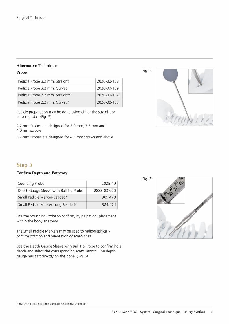
Pedicle preparation may be done using either the straight or curved probe. (Fig. 5)
2.2 mm Probes are designed for 3.0 mm, 3.5 mm and 4.0 mm screws
3.2 mm Probes are designed for 4.5 mm screws and above
Step 3Confirm Depth and Pathway
Sounding Probe 2025-49
Depth Gauge Sleeve with Ball Tip Probe 2883-03-000
Small Pedicle Marker-Beaded* 389.473
Small Pedicle Marker-Long Beaded* 389.474
Use the Sounding Probe to confirm, by palpation, placement within the bony anatomy.
The Small Pedicle Markers may be used to radiographically confirm position and orientation of screw sites.
Use the Depth Gauge Sleeve with Ball Tip Probe to confirm hole depth and select the corresponding screw length. The depth gauge must sit directly on the bone. (Fig. 6)
Fig. 5
Fig. 6
* Instrument does not come standard in Core Instrument Set
Surgical Technique
8 DePuy Synthes SYMPHONY™ OCT System Surgical Technique
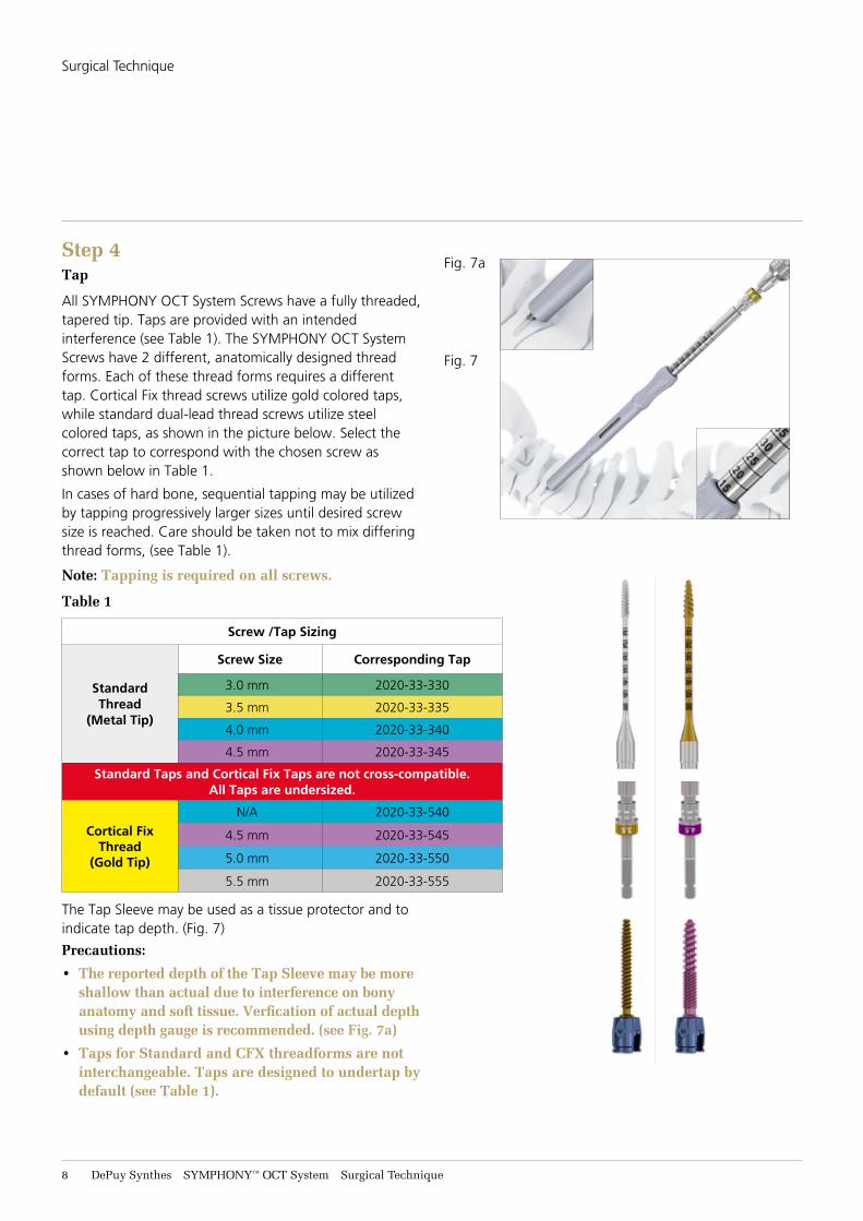
Step 4Tap
All SYMPHONY OCT System Screws have a fully threaded, tapered tip. Taps are provided with an intended interference (see Table 1). The SYMPHONY OCT System Screws have 2 different, anatomically designed thread forms. Each of these thread forms requires a different tap. Cortical Fix thread screws utilize gold colored taps, while standard dual-lead thread screws utilize steel colored taps, as shown in the picture below. Select the correct tap to correspond with the chosen screw as shown below in Table 1.
In cases of hard bone, sequential tapping may be utilized by tapping progressively larger sizes until desired screw size is reached. Care should be taken not to mix differing thread forms, (see Table 1).
Note: Tapping is required on all screws.
Table 1
Screw /Tap Sizing
Standard Thread
(Metal Tip)
Screw Size Corresponding Tap
3.0 mm 2020-33-330
3.5 mm 2020-33-335
4.0 mm 2020-33-340
4.5 mm 2020-33-345
Standard Taps and Cortical Fix Taps are not cross-compatible. All Taps are undersized.
Cortical FixThread
(Gold Tip)
N/A 2020-33-540
4.5 mm 2020-33-545
5.0 mm 2020-33-550
5.5 mm 2020-33-555
The Tap Sleeve may be used as a tissue protector and to indicate tap depth. (Fig. 7)
Precautions:
• The reported depth of the Tap Sleeve may be more shallow than actual due to interference on bony anatomy and soft tissue. Verfication of actual depth using depth gauge is recommended. (see Fig. 7a)
• Taps for Standard and CFX threadforms are not interchangeable. Taps are designed to undertap by default (see Table 1).
Fig. 7a
Fig. 7
Surgical Technique
SYMPHONY™ OCT System Surgical Technique DePuy Synthes 9
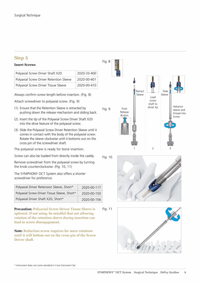
Step 5Insert Screws
Polyaxial Screw Driver Shaft X20 2020-33-400
Polyaxial Screw Driver Retention Sleeve 2020-00-401
Polyaxial Screw Driver Tissue Sleeve 2020-00-410
Always confirm screw length before insertion. (Fig. 8)
Attach screwdriver to polyaxial screw. (Fig. 9)
(1). Ensure that the Retention Sleeve is retracted by pushing down the release mechanism and sliding back.
(2). Insert the tip of the Polyaxial Screw Driver Shaft X20 into the drive feature of the polyaxial screw.
(3). Slide the Polyaxial Screw Driver Retention Sleeve until it comes in contact with the body of the polyaxial screw. Rotate the sleeve clockwise until it bottoms out on the cross pin of the screwdriver shaft.
The polyaxial screw is ready for bone insertion.
Screw can also be loaded from directly inside the caddy.
Remove screwdriver from the polyaxial screw by turning the knob counterclockwise. (Fig. 10, 11)
The SYMPHONY OCT System also offers a shorter screwdriver for preference.
Polyaxial Driver Retension Sleeve, Short* 2020-00-117
Polyaxial Screw Driver Tissue Sleeve, Short* 2020-00-150
Polyaxial Driver Shaft X20, Short* 2020-00-156
Precaution: Polyaxial Screw Driver Tissue Sleeve is optional. If not using, be mindful that not allowing rotation of the retention sleeve during insertion can lead to screw disengagement.
Note: Reduction screw requires far more rotations until it will bottom out on the cross pin of the Screw Driver shaft.
2
Load screw
shaft to driver tip
Fig. 8
Fig. 9
Fig. 10
Fig. 11
1
Retract Sleeve
PushRelease Button
3
Slide Sleeve
Advance sleeve and thread into Screw
* Instrument does not come standard in Core Instrument Set
Surgical Technique
11 DePuy Synthes SYMPHONY™ OCT System Surgical Technique
Surgical Technique
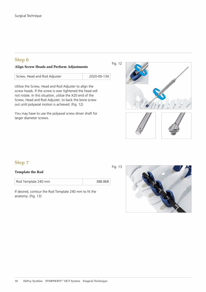
Step 6Align Screw Heads and Perform Adjustments
Screw, Head and Rod Adjuster 2020-00-134
Utilize the Screw, Head and Rod Adjuster to align the screw heads. If the screw is over tightened the head will not rotate. In this situation, utilize the X20 end of the Screw, Head and Rod Adjuster, to back the bone screw out until polyaxial motion is achieved. (Fig. 12)
You may have to use the polyaxial screw driver shaft for larger diameter screws.
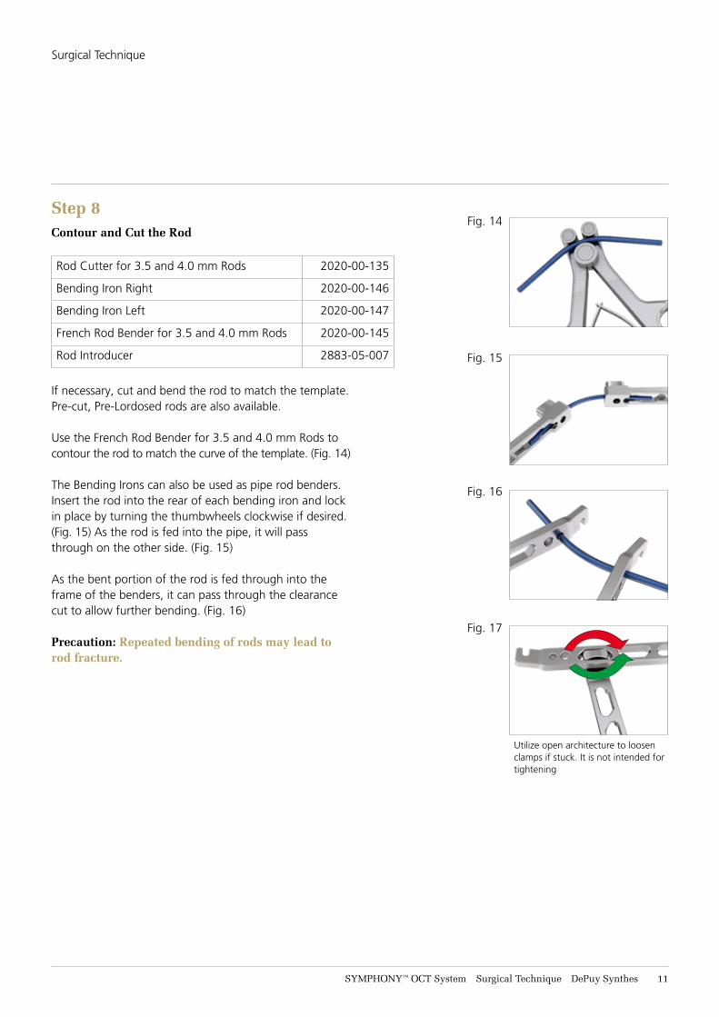
Step 7
Template the Rod
Rod Template 240 mm 388.868
If desired, contour the Rod Template 240 mm to fit the anatomy. (Fig. 13)
Fig. 12
Fig. 13
SYMPHONY™ OCT System Surgical Technique DePuy Synthes 11
Surgical Technique
Step 8Contour and Cut the Rod
Rod Cutter for 3.5 and 4.0 mm Rods 2020-00-135
Bending Iron Right 2020-00-146
Bending Iron Left 2020-00-147
French Rod Bender for 3.5 and 4.0 mm Rods 2020-00-145
Rod Introducer 2883-05-007
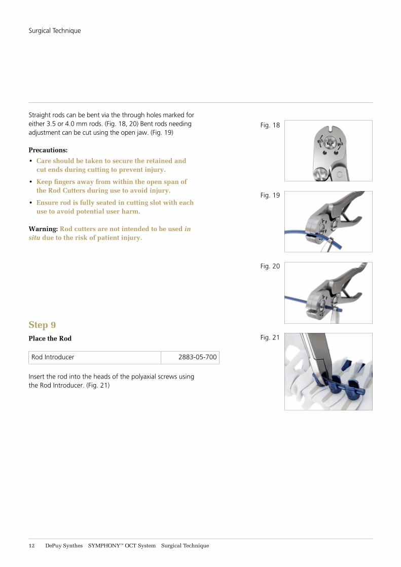
If necessary, cut and bend the rod to match the template. Pre-cut, Pre-Lordosed rods are also available.
Use the French Rod Bender for 3.5 and 4.0 mm Rods to contour the rod to match the curve of the template. (Fig. 14)
The Bending Irons can also be used as pipe rod benders. Insert the rod into the rear of each bending iron and lock in place by turning the thumbwheels clockwise if desired. (Fig. 15) As the rod is fed into the pipe, it will pass through on the other side. (Fig. 15)
As the bent portion of the rod is fed through into the frame of the benders, it can pass through the clearance cut to allow further bending. (Fig. 16)
Precaution: Repeated bending of rods may lead to rod fracture.
Fig. 14
Fig. 15
Fig. 16
Fig. 17
Utilize open architecture to loosen clamps if stuck. It is not intended for tightening
12 DePuy Synthes SYMPHONY™ OCT System Surgical Technique
Straight rods can be bent via the through holes marked for either 3.5 or 4.0 mm rods. (Fig. 18, 20) Bent rods needing adjustment can be cut using the open jaw. (Fig. 19)
Precautions:
• Care should be taken to secure the retained and cut ends during cutting to prevent injury.
• Keep fingers away from within the open span of the Rod Cutters during use to avoid injury.
• Ensure rod is fully seated in cutting slot with each use to avoid potential user harm.
Warning: Rod cutters are not intended to be used in situ due to the risk of patient injury.
Step 9Place the Rod
Rod Introducer 2883-05-700
Insert the rod into the heads of the polyaxial screws using the Rod Introducer. (Fig. 21)
Fig. 21
Fig. 19
Fig. 20
Fig. 18
Surgical Technique
SYMPHONY™ OCT System Surgical Technique DePuy Synthes 13
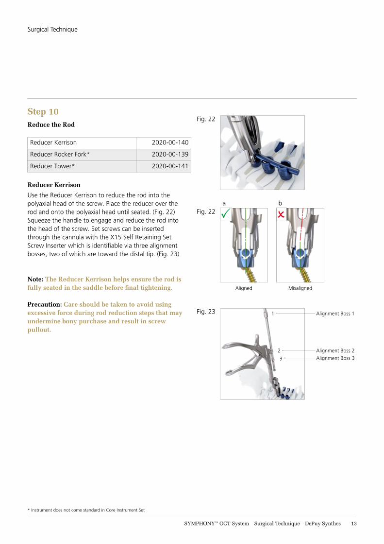
Step 10Reduce the Rod
Reducer Kerrison 2020-00-140
Reducer Rocker Fork* 2020-00-139
Reducer Tower* 2020-00-141
Reducer Kerrison
Use the Reducer Kerrison to reduce the rod into the polyaxial head of the screw. Place the reducer over the rod and onto the polyaxial head until seated. (Fig. 22)Squeeze the handle to engage and reduce the rod into the head of the screw. Set screws can be inserted through the cannula with the X15 Self Retaining Set Screw Inserter which is identifiable via three alignment bosses, two of which are toward the distal tip. (Fig. 23)
Note: The Reducer Kerrison helps ensure the rod is fully seated in the saddle before final tightening.
Precaution: Care should be taken to avoid using excessive force during rod reduction steps that may undermine bony purchase and result in screw pullout.
Fig. 22
Fig. 22a b
Aligned Misaligned
P O
Fig. 23
2 Alignment Boss 2
1 Alignment Boss 1
Alignment Boss 33
Surgical Technique
* Instrument does not come standard in Core Instrument Set
14 DePuy Synthes SYMPHONY™ OCT System Surgical Technique
Fig. 24
Fig. 25
Fig. 26
Fig. 27
Fig. 28
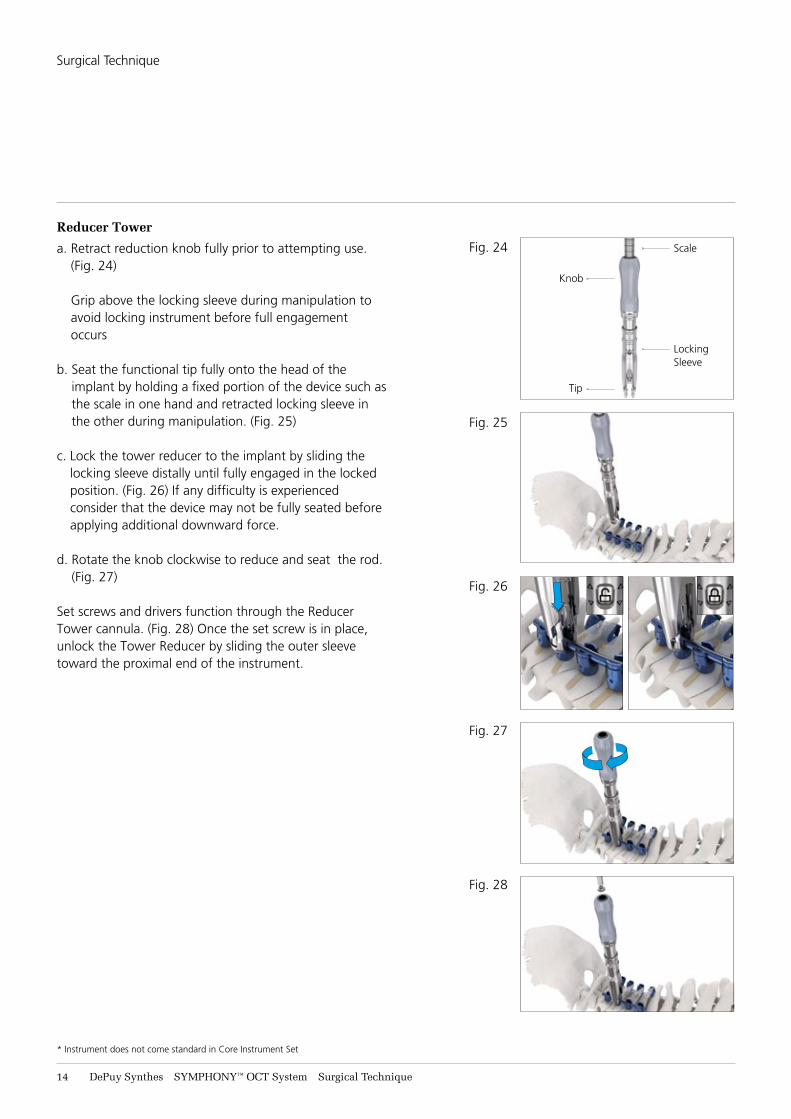
Reducer Tower
a. Retract reduction knob fully prior to attempting use. (Fig. 24) Grip above the locking sleeve during manipulation to avoid locking instrument before full engagement occurs
b. Seat the functional tip fully onto the head of the implant by holding a fixed portion of the device such as the scale in one hand and retracted locking sleeve in the other during manipulation. (Fig. 25)
c. Lock the tower reducer to the implant by sliding the locking sleeve distally until fully engaged in the locked position. (Fig. 26) If any difficulty is experienced consider that the device may not be fully seated before applying additional downward force.
d. Rotate the knob clockwise to reduce and seat the rod. (Fig. 27)
Set screws and drivers function through the Reducer Tower cannula. (Fig. 28) Once the set screw is in place, unlock the Tower Reducer by sliding the outer sleeve toward the proximal end of the instrument.
Scale
Knob
Tip
Locking Sleeve
Surgical Technique
* Instrument does not come standard in Core Instrument Set
SYMPHONY™ OCT System Surgical Technique DePuy Synthes 15
Fig. 29
Fig. 29a
Fig. 30
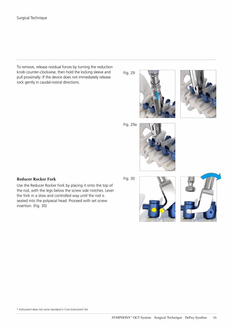
To remove, release residual forces by turning the reduction knob counter-clockwise, then hold the locking sleeve and pull proximally. If the device does not immediately release rock gently in caudal-rostral directions.
Reducer Rocker Fork
Use the Reducer Rocker Fork by placing it onto the top of the rod, with the legs below the screw side notches. Lever the fork in a slow and controlled way until the rod is seated into the polyaxial head. Proceed with set screw insertion. (Fig. 30)
Surgical Technique
* Instrument does not come standard in Core Instrument Set
16 DePuy Synthes SYMPHONY™ OCT System Surgical Technique
Step 11Insert Set Screws
X15 Self Retaining Set Screw Inserter 2020-00-407
Dual Sided Set Screw Inserter* 2020-00-402
Insert the set screws using the X15 Self Retaining Set Screw Inserter or the Dual Sided Set Screw Inserter. Set screws can be inserted through either the Counter Torque or the Reducer Kerrison using the X15 Self Retaining Set Screw inserter. (Fig. 31)
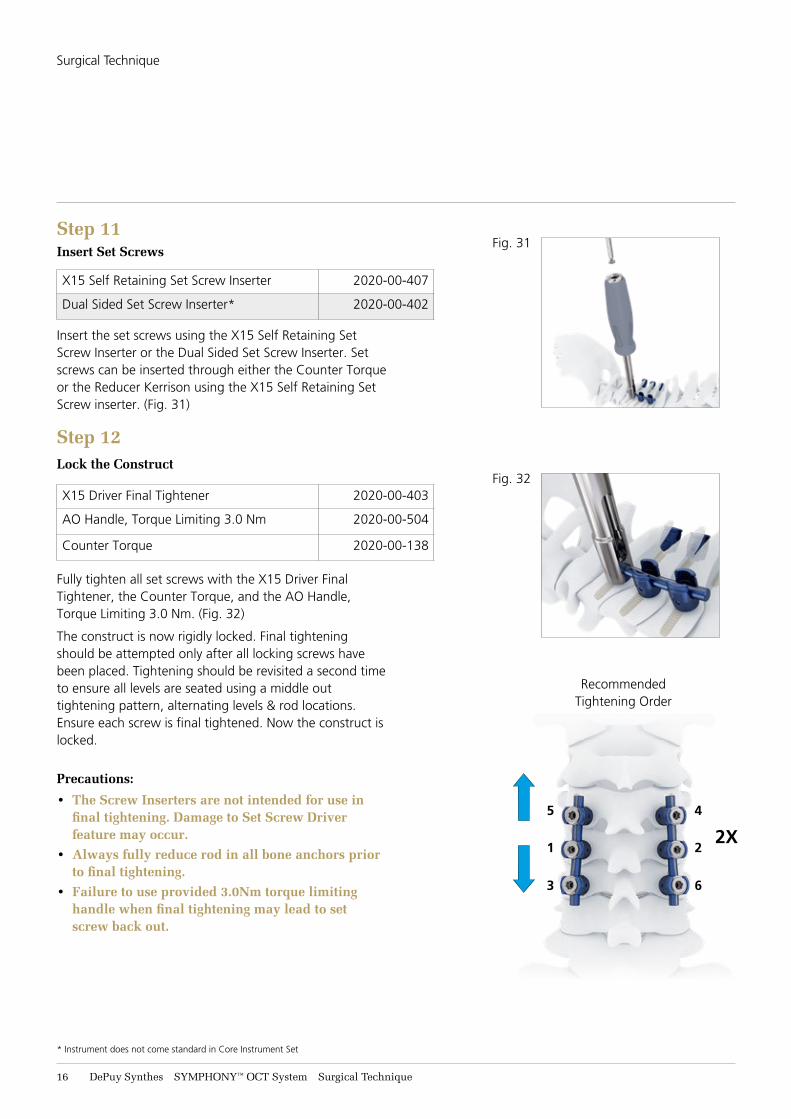
Step 12Lock the Construct
X15 Driver Final Tightener 2020-00-403
AO Handle, Torque Limiting 3.0 Nm 2020-00-504
Counter Torque 2020-00-138
Fully tighten all set screws with the X15 Driver Final Tightener, the Counter Torque, and the AO Handle, Torque Limiting 3.0 Nm. (Fig. 32)
The construct is now rigidly locked. Final tightening should be attempted only after all locking screws have been placed. Tightening should be revisited a second time to ensure all levels are seated using a middle out tightening pattern, alternating levels & rod locations. Ensure each screw is final tightened. Now the construct is locked.
Precautions:
• The Screw Inserters are not intended for use in final tightening. Damage to Set Screw Driver feature may occur.
• Always fully reduce rod in all bone anchors prior to final tightening.
• Failure to use provided 3.0Nm torque limiting handle when final tightening may lead to set screw back out.
Surgical Technique
Fig. 32
Recommended Tightening Order
2X1
3 6
45
2
Fig. 31
* Instrument does not come standard in Core Instrument Set
SYMPHONY™ OCT System Surgical Technique DePuy Synthes 17
2X
Fig. 33
Fig. 34
Fig. 35
Fig. 36
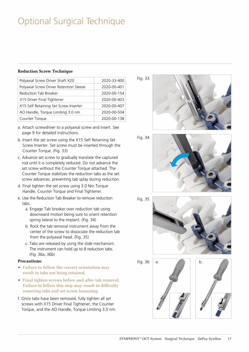
Reduction Screw Technique
Polyaxial Screw Driver Shaft X20 2020-33-400
Polyaxial Screw Driver Retention Sleeve 2020-00-401
Reduction Tab Breaker 2020-00-154
X15 Driver Final Tightener 2020-00-403
X15 Self Retaining Set Screw Inserter 2020-00-407
AO Handle, Torque Limiting 3.0 nm 2020-00-504
Counter Torque 2020-00-138
a. Attach screwdriver to a polyaxial screw and insert. See page 9 for detailed instructions.
b. Insert the set screw using the X15 Self Retaining Set Screw Inserter. Set screw must be inserted through the Counter Torque. (Fig. 33)
c. Advance set screw to gradually translate the captured rod until it is completely reduced. Do not advance the set screw without the Counter Torque attached. The Counter Torque stabilizes the reduction tabs as the set screw advances, preventing tab splay during reduction.
d. Final tighten the set screw using 3.0 Nm Torque Handle, Counter Torque and Final Tightener.
e. Use the Reduction Tab Breaker to remove reduction tabs.
a. Engage Tab breaker over reduction tab using downward motion being sure to orient retention spring lateral to the implant. (Fig. 34)
b. Rock the tab removal instrument away from the center of the screw to dissociate the reduction tab from the polyaxial head. (Fig. 35)
c. Tabs are released by using the slide mechanism. The instrument can hold up to 8 reduction tabs. (Fig. 36a, 36b)
Precautions: • Failure to follow the correct orientation may
result in tabs not being retained.
• Final tighten screws before and after tab removal. Failure to follow this step may result in difficulty removing tabs and set screw loosening.
f. Once tabs have been removed, fully tighten all set screws with X15 Driver Final Tightener, the Counter Torque, and the AO Handle, Torque Limiting 3.0 nm.
Optional Surgical Technique
a. b.

18 DePuy Synthes SYMPHONY™ OCT System Surgical Technique
Optional Tab Breaking Technique
Rod Holder 03.614.023
g. Use the Rod Clamp to remove reduction tabs. a. Clasp upper portion of Tab within jaws of Rod
Clamp to capture securely. Close jaws until the ratchet lock engages. (Fig. 38)
b. Pivot the Rod Clamp away from the center of the screw to dissociate the reduction tab from the polyaxial head. (Fig. 39)
c. Tab is held securely by the Rod Clamp until released by disengaging the latch.
Fig. 37
Fig. 38
Fig. 39
Optional Surgical Technique
SYMPHONY™ OCT System Surgical Technique DePuy Synthes 19
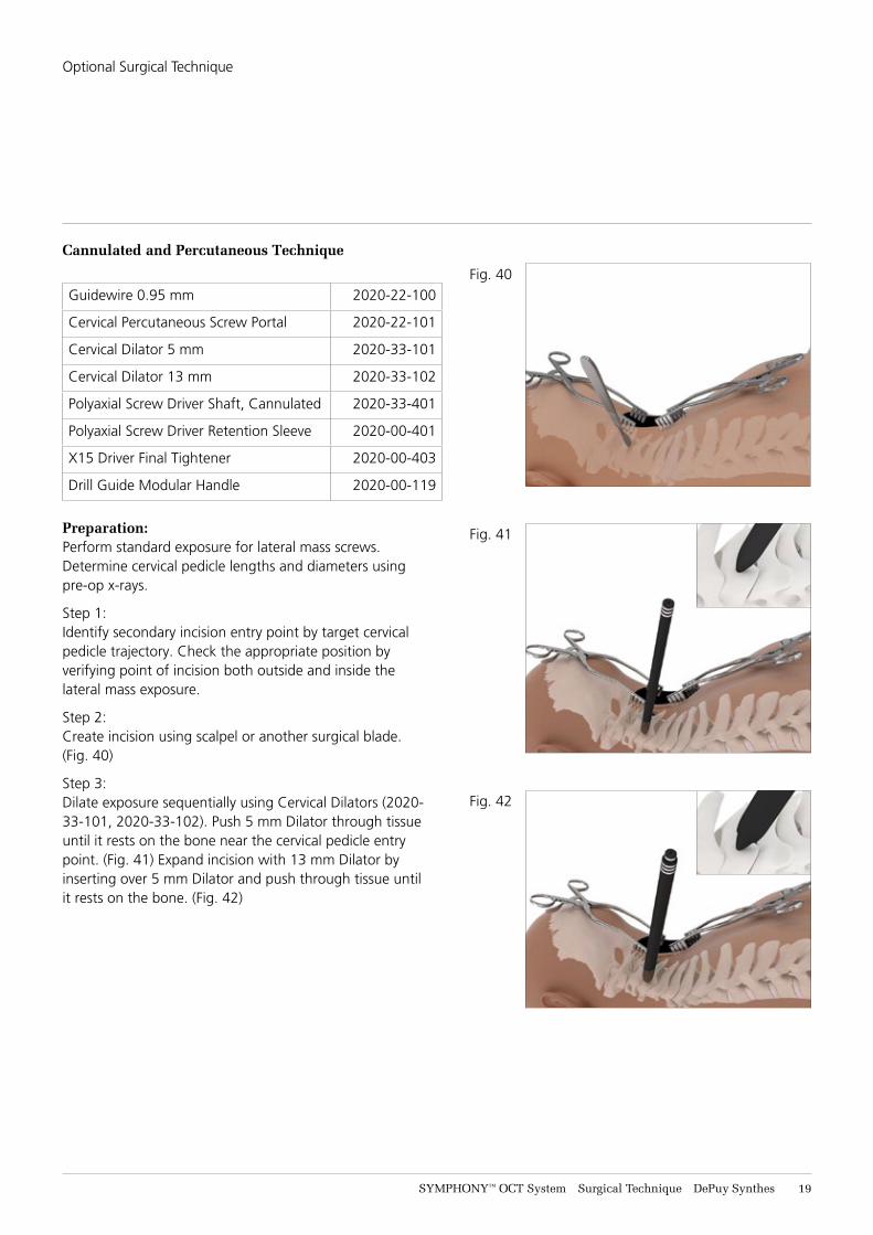
Cannulated and Percutaneous Technique
Guidewire 0.95 mm 2020-22-100
Cervical Percutaneous Screw Portal 2020-22-101
Cervical Dilator 5 mm 2020-33-101
Cervical Dilator 13 mm 2020-33-102
Polyaxial Screw Driver Shaft, Cannulated 2020-33-401
Polyaxial Screw Driver Retention Sleeve 2020-00-401
X15 Driver Final Tightener 2020-00-403
Drill Guide Modular Handle 2020-00-119
Preparation:Perform standard exposure for lateral mass screws. Determine cervical pedicle lengths and diameters using pre-op x-rays.
Step 1:Identify secondary incision entry point by target cervical pedicle trajectory. Check the appropriate position by verifying point of incision both outside and inside the lateral mass exposure.
Step 2: Create incision using scalpel or another surgical blade. (Fig. 40)
Step 3:Dilate exposure sequentially using Cervical Dilators (2020-33-101, 2020-33-102). Push 5 mm Dilator through tissue until it rests on the bone near the cervical pedicle entry point. (Fig. 41) Expand incision with 13 mm Dilator by inserting over 5 mm Dilator and push through tissue until it rests on the bone. (Fig. 42)
Fig. 40
Fig. 41
Fig. 42
Optional Surgical Technique
21 DePuy Synthes SYMPHONY™ OCT System Surgical Technique
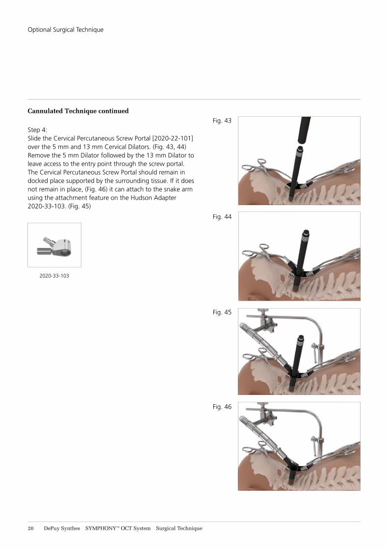
Cannulated Technique continued
Step 4:Slide the Cervical Percutaneous Screw Portal [2020-22-101] over the 5 mm and 13 mm Cervical Dilators. (Fig. 43, 44) Remove the 5 mm Dilator followed by the 13 mm Dilator to leave access to the entry point through the screw portal. The Cervical Percutaneous Screw Portal should remain in docked place supported by the surrounding tissue. If it does not remain in place, (Fig. 46) it can attach to the snake arm using the attachment feature on the Hudson Adapter 2020-33-103. (Fig. 45)
2020-33-103
Fig. 43
Fig. 44
Fig. 45
Fig. 46
Optional Surgical Technique
SYMPHONY™ OCT System Surgical Technique DePuy Synthes 21
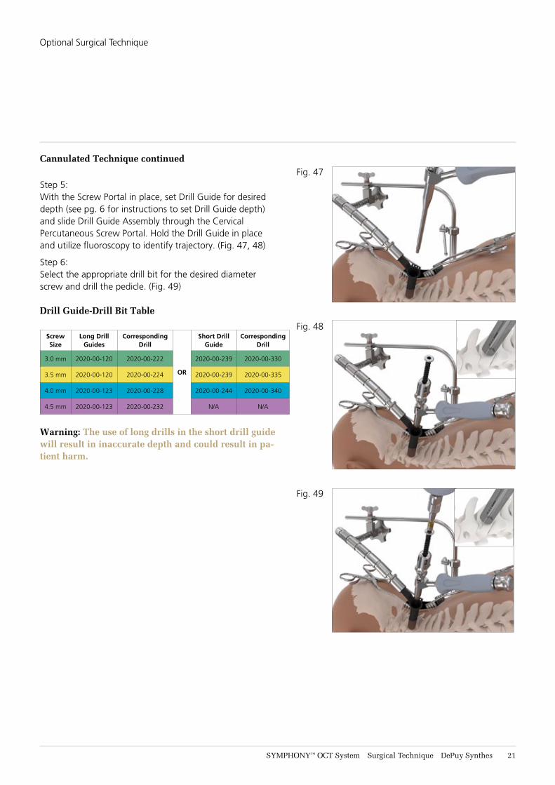
Cannulated Technique continued
Step 5: With the Screw Portal in place, set Drill Guide for desired depth (see pg. 6 for instructions to set Drill Guide depth) and slide Drill Guide Assembly through the Cervical Percutaneous Screw Portal. Hold the Drill Guide in place and utilize fluoroscopy to identify trajectory. (Fig. 47, 48)
Step 6:Select the appropriate drill bit for the desired diameter screw and drill the pedicle. (Fig. 49)
Drill Guide-Drill Bit Table
Screw Size
Long Drill Guides
Corresponding Drill
OR
Short Drill Guide
Corresponding Drill
3.0 mm 2020-00-120 2020-00-222 2020-00-239 2020-00-330
3.5 mm 2020-00-120 2020-00-224 2020-00-239 2020-00-335
4.0 mm 2020-00-123 2020-00-228 2020-00-244 2020-00-340
4.5 mm 2020-00-123 2020-00-232 N/A N/A
Warning: The use of long drills in the short drill guide will result in inaccurate depth and could result in pa-tient harm.
Fig. 47
Fig. 48
Fig. 49
Optional Surgical Technique
22 DePuy Synthes SYMPHONY™ OCT System Surgical Technique
Cannulated Technique continued
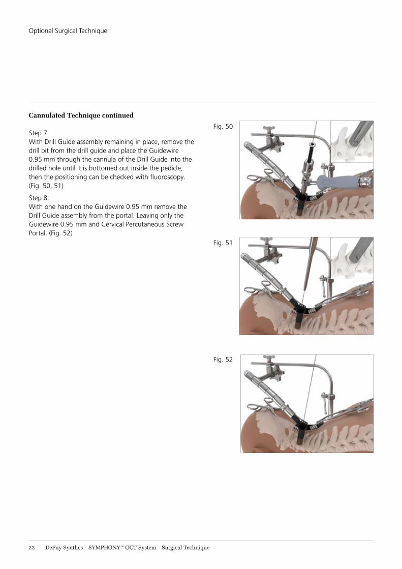
Step 7With Drill Guide assembly remaining in place, remove the drill bit from the drill guide and place the Guidewire 0.95 mm through the cannula of the Drill Guide into the drilled hole until it is bottomed out inside the pedicle, then the positioning can be checked with fluoroscopy. (Fig. 50, 51)
Step 8:With one hand on the Guidewire 0.95 mm remove the Drill Guide assembly from the portal. Leaving only the Guidewire 0.95 mm and Cervical Percutaneous Screw Portal. (Fig. 52)
Fig. 50
Fig. 51
Fig. 52
Optional Surgical Technique
SYMPHONY™ OCT System Surgical Technique DePuy Synthes 23
Cannulated Technique continued
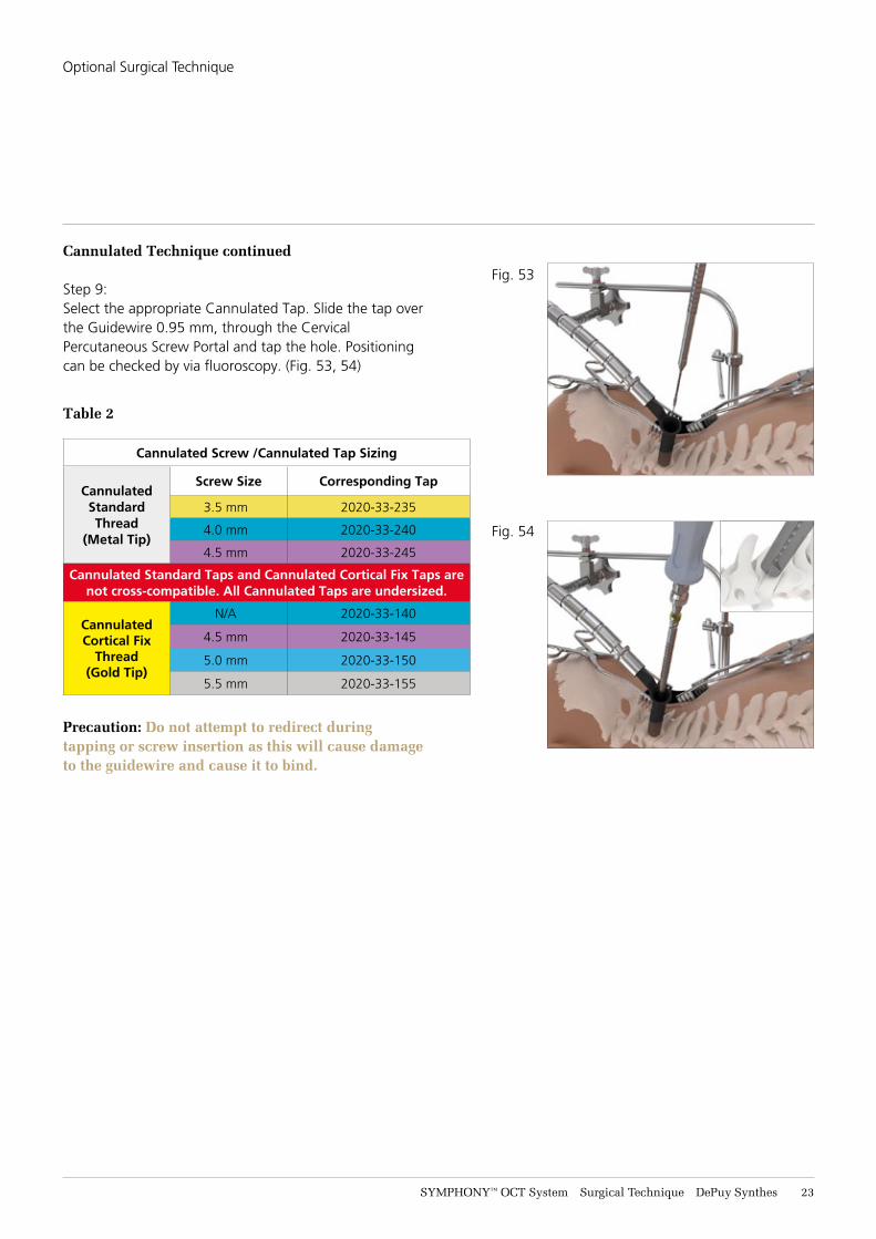
Step 9:Select the appropriate Cannulated Tap. Slide the tap over the Guidewire 0.95 mm, through the Cervical Percutaneous Screw Portal and tap the hole. Positioning can be checked by via fluoroscopy. (Fig. 53, 54)
Table 2
Cannulated Screw /Cannulated Tap Sizing
CannulatedStandard Thread
(Metal Tip)
Screw Size Corresponding Tap
3.5 mm 2020-33-235
4.0 mm 2020-33-240
4.5 mm 2020-33-245
Cannulated Standard Taps and Cannulated Cortical Fix Taps are not cross-compatible. All Cannulated Taps are undersized.
CannulatedCortical Fix
Thread(Gold Tip)
N/A 2020-33-140
4.5 mm 2020-33-145
5.0 mm 2020-33-150
5.5 mm 2020-33-155
Precaution: Do not attempt to redirect during tapping or screw insertion as this will cause damage to the guidewire and cause it to bind.
Fig. 53
Fig. 54
Optional Surgical Technique
24 DePuy Synthes SYMPHONY™ OCT System Surgical Technique
Cannulated Technique continued
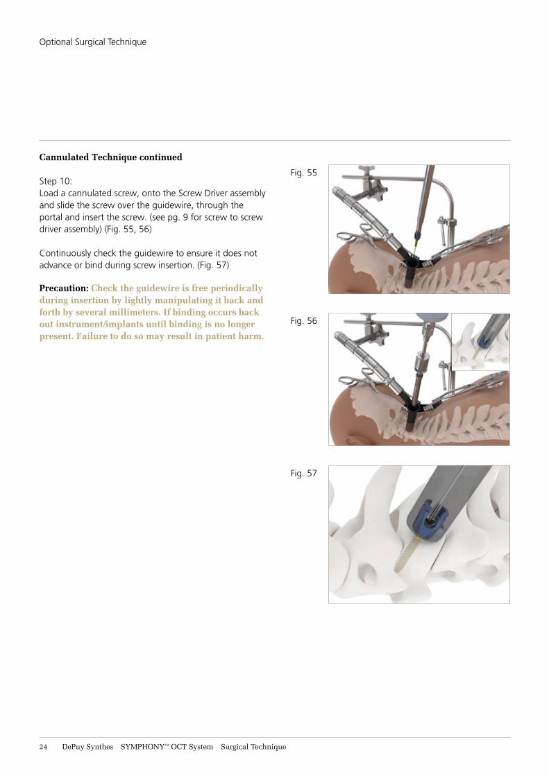
Step 10:Load a cannulated screw, onto the Screw Driver assembly and slide the screw over the guidewire, through the portal and insert the screw. (see pg. 9 for screw to screw driver assembly) (Fig. 55, 56)
Continuously check the guidewire to ensure it does not advance or bind during screw insertion. (Fig. 57)
Precaution: Check the guidewire is free periodically during insertion by lightly manipulating it back and forth by several millimeters. If binding occurs back out instrument/implants until binding is no longer present. Failure to do so may result in patient harm.
Fig. 55
Fig. 56
Fig. 57
Optional Surgical Technique
SYMPHONY™ OCT System Surgical Technique DePuy Synthes 25
Cannulated Technique continued
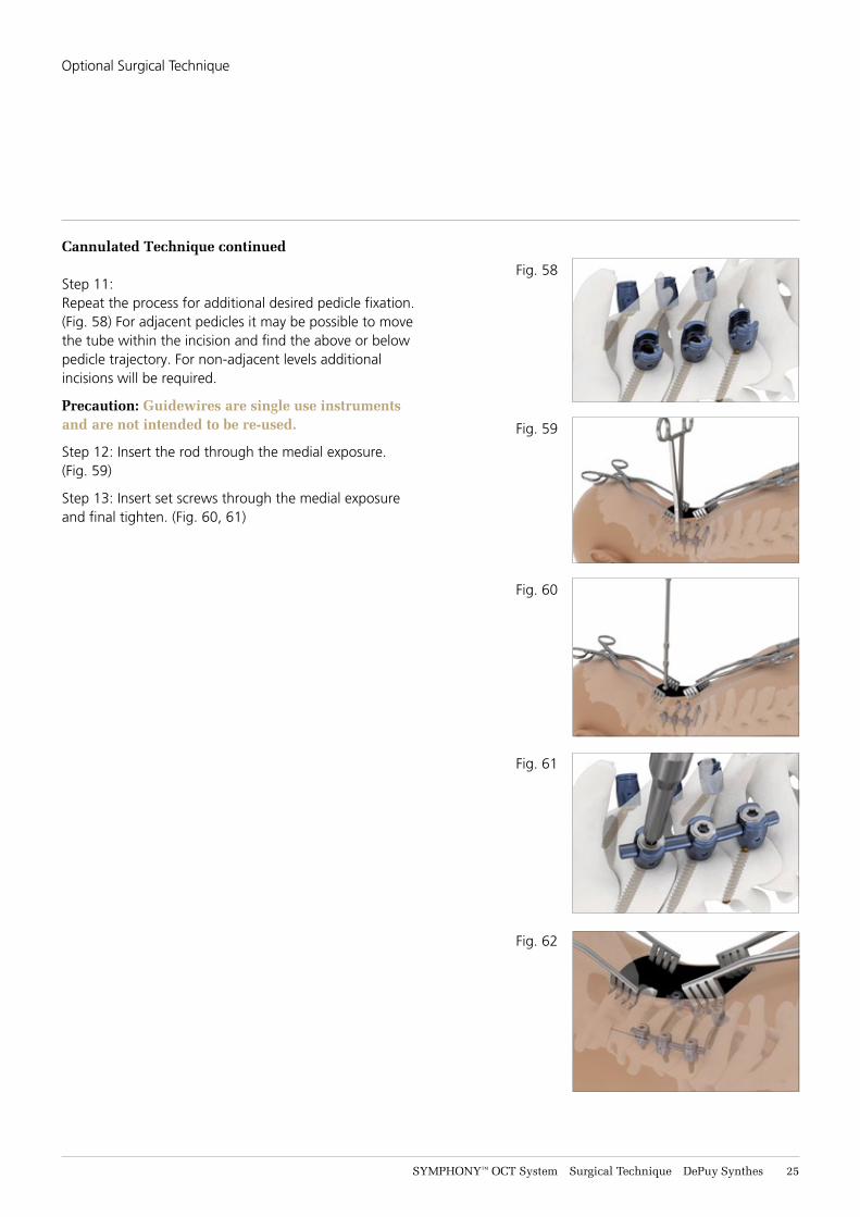
Step 11:Repeat the process for additional desired pedicle fixation. (Fig. 58) For adjacent pedicles it may be possible to move the tube within the incision and find the above or below pedicle trajectory. For non-adjacent levels additional incisions will be required.
Precaution: Guidewires are single use instruments and are not intended to be re-used.
Step 12: Insert the rod through the medial exposure. (Fig. 59)
Step 13: Insert set screws through the medial exposure and final tighten. (Fig. 60, 61)
Fig. 58
Fig. 59
Fig. 60
Fig. 61
Fig. 62
Optional Surgical Technique
26 DePuy Synthes SYMPHONY™ OCT System Surgical Technique
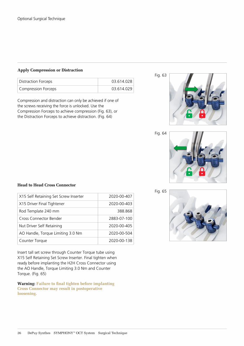
Apply Compression or Distraction
Distraction Forceps 03.614.028
Compression Forceps 03.614.029
Compression and distraction can only be achieved if one of the screws receiving the force is unlocked. Use the Compression Forceps to achieve compression (Fig. 63), or the Distraction Forceps to achieve distraction. (Fig. 64)
Head to Head Cross Connector
X15 Self Retaining Set Screw Inserter 2020-00-407
X15 Driver Final Tightener 2020-00-403
Rod Template 240 mm 388.868
Cross Connector Bender 2883-07-100
Nut Driver Self Retaining 2020-00-405
AO Handle, Torque Limiting 3.0 Nm 2020-00-504
Counter Torque 2020-00-138
Insert tall set screw through Counter Torque tube using X15 Self Retaining Set Screw Inserter. Final tighten when ready before implanting the H2H Cross Connector using the AO Handle, Torque Limiting 3.0 Nm and Counter Torque. (Fig. 65)
Warning: Failure to final tighten before implanting Cross Connector may result in postoperative loosening.
Fig. 63
Fig. 64
Fig. 65
Optional Surgical Technique
SYMPHONY™ OCT System Surgical Technique DePuy Synthes 27
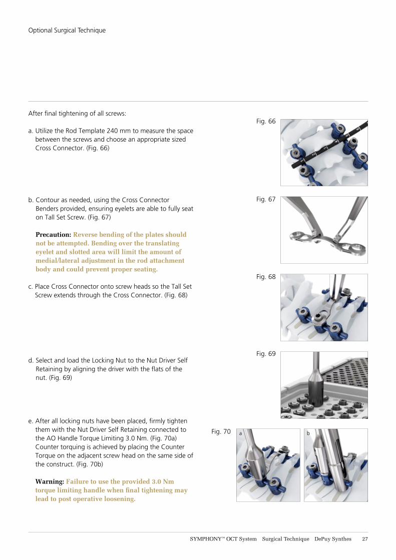
After final tightening of all screws:
a. Utilize the Rod Template 240 mm to measure the space between the screws and choose an appropriate sized Cross Connector. (Fig. 66)
b. Contour as needed, using the Cross Connector Benders provided, ensuring eyelets are able to fully seat on Tall Set Screw. (Fig. 67) Precaution: Reverse bending of the plates should not be attempted. Bending over the translating eyelet and slotted area will limit the amount of medial/lateral adjustment in the rod attachment body and could prevent proper seating.
c. Place Cross Connector onto screw heads so the Tall Set Screw extends through the Cross Connector. (Fig. 68)
d. Select and load the Locking Nut to the Nut Driver Self Retaining by aligning the driver with the flats of the nut. (Fig. 69)
e. After all locking nuts have been placed, firmly tighten them with the Nut Driver Self Retaining connected to the AO Handle Torque Limiting 3.0 Nm. (Fig. 70a) Counter torquing is achieved by placing the Counter Torque on the adjacent screw head on the same side of the construct. (Fig. 70b) Warning: Failure to use the provided 3.0 Nm torque limiting handle when final tightening may lead to post operative loosening.
Fig. 66
Fig. 67
Fig. 68
Fig. 69
Fig. 70 a b
Optional Surgical Technique
28 DePuy Synthes SYMPHONY™ OCT System Surgical Technique
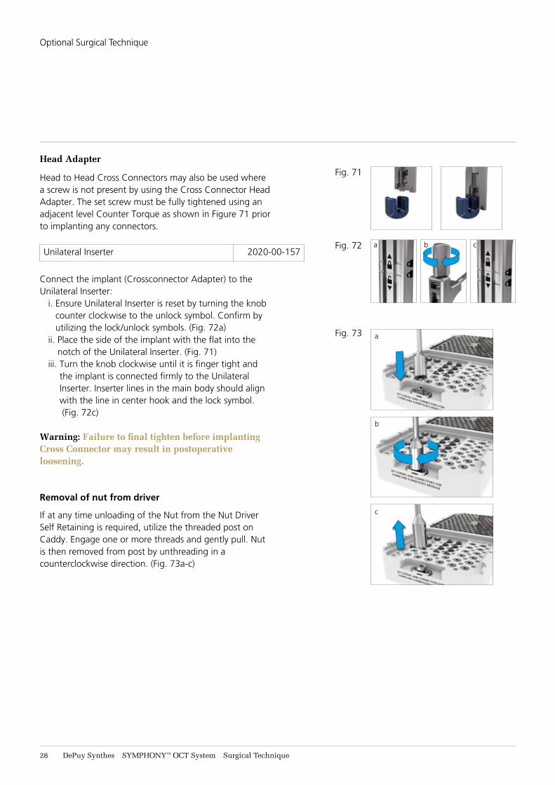
Head Adapter
Head to Head Cross Connectors may also be used where a screw is not present by using the Cross Connector Head Adapter. The set screw must be fully tightened using an adjacent level Counter Torque as shown in Figure 71 prior to implanting any connectors.
Unilateral Inserter 2020-00-157
Connect the implant (Crossconnector Adapter) to the Unilateral Inserter:
i. Ensure Unilateral Inserter is reset by turning the knob counter clockwise to the unlock symbol. Confirm by utilizing the lock/unlock symbols. (Fig. 72a)
ii. Place the side of the implant with the flat into the notch of the Unilateral Inserter. (Fig. 71)
iii. Turn the knob clockwise until it is finger tight and the implant is connected firmly to the Unilateral Inserter. Inserter lines in the main body should align with the line in center hook and the lock symbol. (Fig. 72c)
Warning: Failure to final tighten before implanting Cross Connector may result in postoperative loosening.
Removal of nut from driver
If at any time unloading of the Nut from the Nut Driver Self Retaining is required, utilize the threaded post on Caddy. Engage one or more threads and gently pull. Nut is then removed from post by unthreading in a counterclockwise direction. (Fig. 73a-c)
Fig. 73
b
c
a
a b c
Fig. 71
Fig. 72
Optional Surgical Technique
SYMPHONY™ OCT System Surgical Technique DePuy Synthes 29
a
b
c
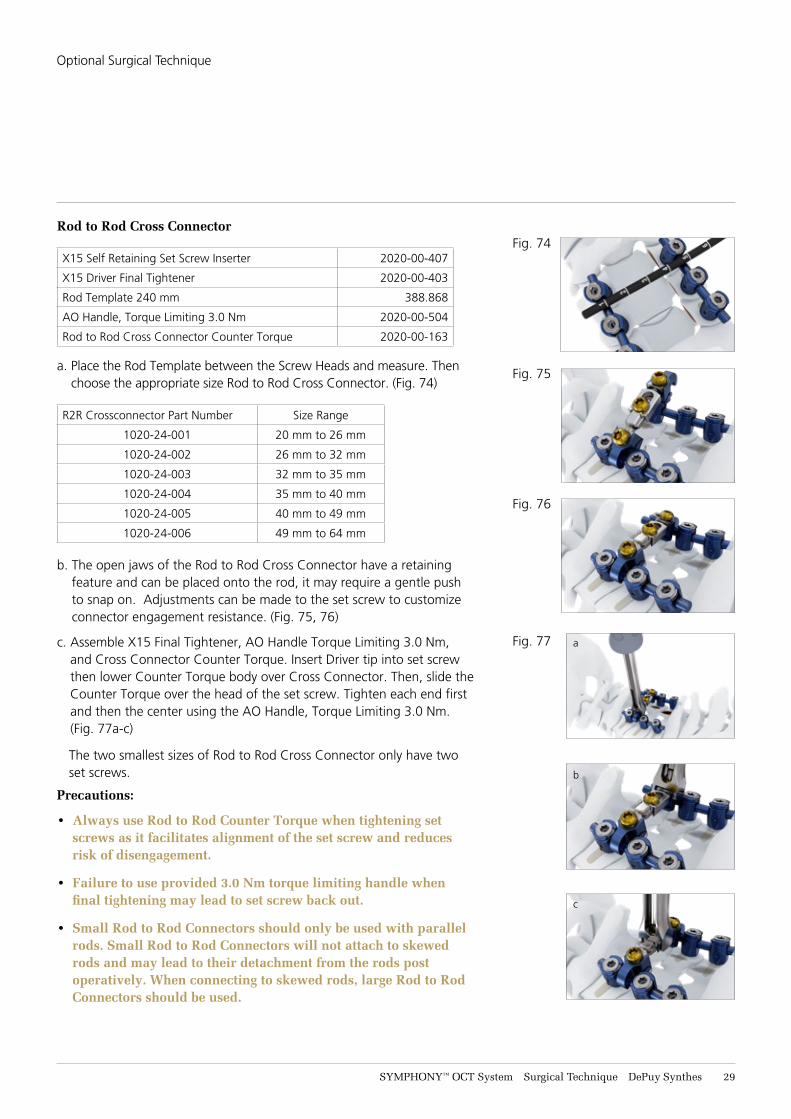
Rod to Rod Cross Connector
X15 Self Retaining Set Screw Inserter 2020-00-407
X15 Driver Final Tightener 2020-00-403
Rod Template 240 mm 388.868
AO Handle, Torque Limiting 3.0 Nm 2020-00-504
Rod to Rod Cross Connector Counter Torque 2020-00-163
a. Place the Rod Template between the Screw Heads and measure. Then choose the appropriate size Rod to Rod Cross Connector. (Fig. 74)
R2R Crossconnector Part Number Size Range
1020-24-001 20 mm to 26 mm
1020-24-002 26 mm to 32 mm
1020-24-003 32 mm to 35 mm
1020-24-004 35 mm to 40 mm
1020-24-005 40 mm to 49 mm
1020-24-006 49 mm to 64 mm
b. The open jaws of the Rod to Rod Cross Connector have a retaining feature and can be placed onto the rod, it may require a gentle push to snap on. Adjustments can be made to the set screw to customize connector engagement resistance. (Fig. 75, 76)
c. Assemble X15 Final Tightener, AO Handle Torque Limiting 3.0 Nm, and Cross Connector Counter Torque. Insert Driver tip into set screw then lower Counter Torque body over Cross Connector. Then, slide the Counter Torque over the head of the set screw. Tighten each end first and then the center using the AO Handle, Torque Limiting 3.0 Nm. (Fig. 77a-c)
The two smallest sizes of Rod to Rod Cross Connector only have two set screws.
Precautions: • Always use Rod to Rod Counter Torque when tightening set
screws as it facilitates alignment of the set screw and reduces risk of disengagement.
• Failure to use provided 3.0 Nm torque limiting handle when final tightening may lead to set screw back out.
• Small Rod to Rod Connectors should only be used with parallel rods. Small Rod to Rod Connectors will not attach to skewed rods and may lead to their detachment from the rods post operatively. When connecting to skewed rods, large Rod to Rod Connectors should be used.
Fig. 74
Fig. 75
Fig. 76
Fig. 77
Optional Surgical Technique
31 DePuy Synthes SYMPHONY™ OCT System Surgical Technique
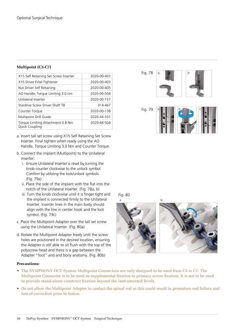
Multipoint (C3-C7)
X15 Self Retaining Set Screw Inserter 2020-00-407
X15 Driver Final Tightener 2020-00-403
Nut Driver Self Retaining 2020-00-405
AO Handle, Torque Limiting 3.0 nm 2020-00-504
Unilateral Inserter 2020-00-157
Stardrive Screw Driver Shaft T8 314.467
Counter Torque 2020-00-138
Multipoint Drill Guide 2020-44-101
Torque Limiting Attachment 0.8 Nm Quick Coupling
2020-44-504
a. Insert tall set screw using X15 Self Retaining Set Screw Inserter. Final tighten when ready using the AO Handle, Torque Limiting 3.0 Nm and Counter Torque.
b. Connect the implant (Multipoint) to the Unilateral Inserter: i. Ensure Unilateral Inserter is reset by turning the
knob counter clockwise to the unlock symbol. Confirm by utilizing the lock/unlock symbols. (Fig. 79a)
ii. Place the side of the implant with the flat into the notch of the Unilateral Inserter. (Fig. 78a, b)
iii. Turn the knob clockwise until it is finger tight and the implant is connected firmly to the Unilateral Inserter. Inserter lines in the main body should align with the line in center hook and the lock symbol. (Fig. 79c)
c. Place the Multipoint Adapter over the tall set screw using the Unilateral Inserter. (Fig. 80a)
d. Rotate the Multipoint Adapter freely until the screw holes are positioned in the desired location, ensuring the Adapter is still able to sit flush with the top of the polyscrew head and there is a gap between the Adapter “foot” and and bony anatomy. (Fig. 80b)
Precautions:
• The SYMPHONY OCT System Multipoint Connectors are only designed to be used from C3 to C7. The Mulitpoint Connector is to be used as supplemental fixation to primary screw fixation. It is not to be used to provide stand-alone construct fixation beyond the instrumented levels.
• Do not allow the Multipoint Adapter to contact the spinal rod as this could result in premature rod failure and loss of correction prior to fusion.
Fig. 78 a b
Fig. 79 a b c
Fig. 80a b
Optional Surgical Technique
SYMPHONY™ OCT System Surgical Technique DePuy Synthes 31
Multipoint (C3-C7)
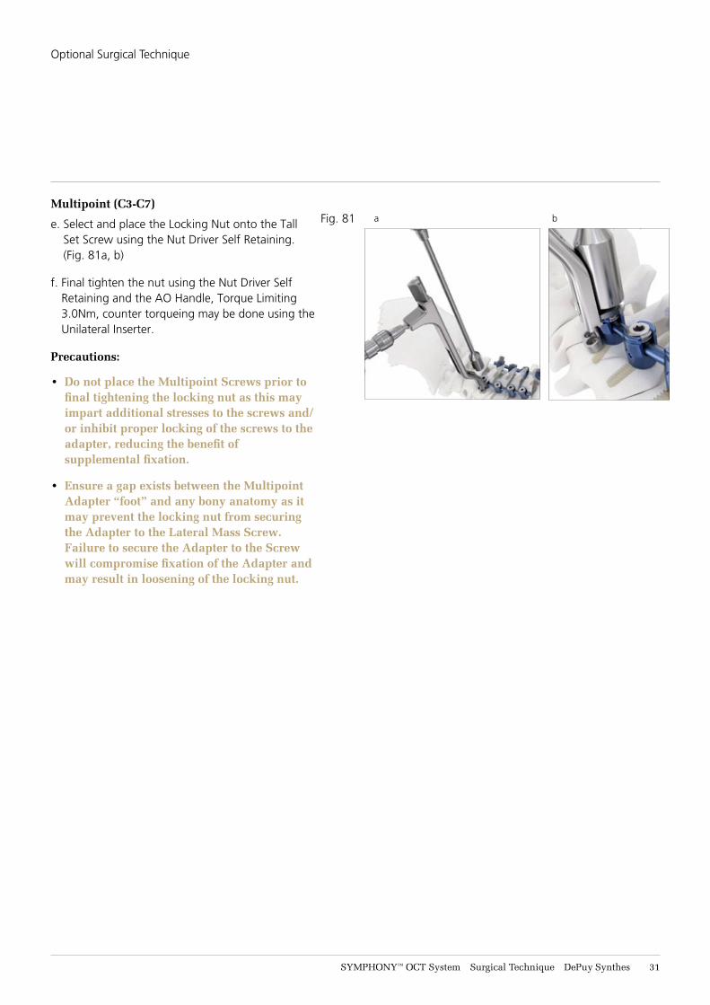
e. Select and place the Locking Nut onto the Tall Set Screw using the Nut Driver Self Retaining. (Fig. 81a, b)
f. Final tighten the nut using the Nut Driver Self Retaining and the AO Handle, Torque Limiting 3.0Nm, counter torqueing may be done using the Unilateral Inserter.
Precautions:
• Do not place the Multipoint Screws prior to final tightening the locking nut as this may impart additional stresses to the screws and/or inhibit proper locking of the screws to the adapter, reducing the benefit of supplemental fixation.
• Ensure a gap exists between the Multipoint
Adapter “foot” and any bony anatomy as it may prevent the locking nut from securing the Adapter to the Lateral Mass Screw. Failure to secure the Adapter to the Screw will compromise fixation of the Adapter and may result in loosening of the locking nut.
Fig. 81 a b
Optional Surgical Technique
32 DePuy Synthes SYMPHONY™ OCT System Surgical Technique
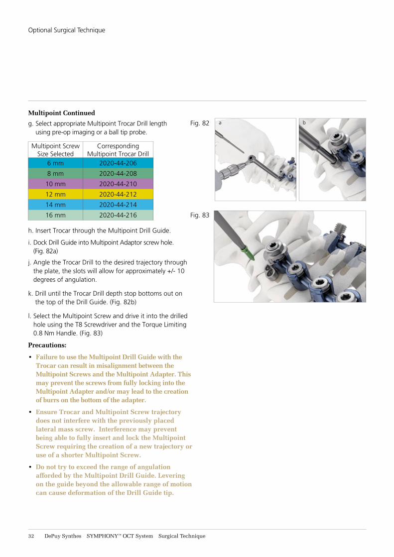
Multipoint Continued
g. Select appropriate Multipoint Trocar Drill length using pre-op imaging or a ball tip probe.
Multipoint ScrewSize Selected
CorrespondingMultipoint Trocar Drill
6 mm 2020-44-206
8 mm 2020-44-208
10 mm 2020-44-210
12 mm 2020-44-212
14 mm 2020-44-214
16 mm 2020-44-216
h. Insert Trocar through the Multipoint Drill Guide.
i. Dock Drill Guide into Multipoint Adaptor screw hole. (Fig. 82a)
j. Angle the Trocar Drill to the desired trajectory through the plate, the slots will allow for approximately +/- 10 degrees of angulation.
k. Drill until the Trocar Drill depth stop bottoms out on the top of the Drill Guide. (Fig. 82b)
l. Select the Multipoint Screw and drive it into the drilled hole using the T8 Screwdriver and the Torque Limiting 0.8 Nm Handle. (Fig. 83)
Precautions:
• Failure to use the Multipoint Drill Guide with the Trocar can result in misalignment between the Multipoint Screws and the Multipoint Adapter. This may prevent the screws from fully locking into the Multipoint Adapter and/or may lead to the creation of burrs on the bottom of the adapter.
• Ensure Trocar and Multipoint Screw trajectory does not interfere with the previously placed lateral mass screw. Interference may prevent being able to fully insert and lock the Multipoint Screw requiring the creation of a new trajectory or use of a shorter Multipoint Screw.
• Do not try to exceed the range of angulation afforded by the Multipoint Drill Guide. Levering on the guide beyond the allowable range of motion can cause deformation of the Drill Guide tip.
Fig. 82
Fig. 83
a b
Optional Surgical Technique
SYMPHONY™ OCT System Surgical Technique DePuy Synthes 33
Multipoint Continued
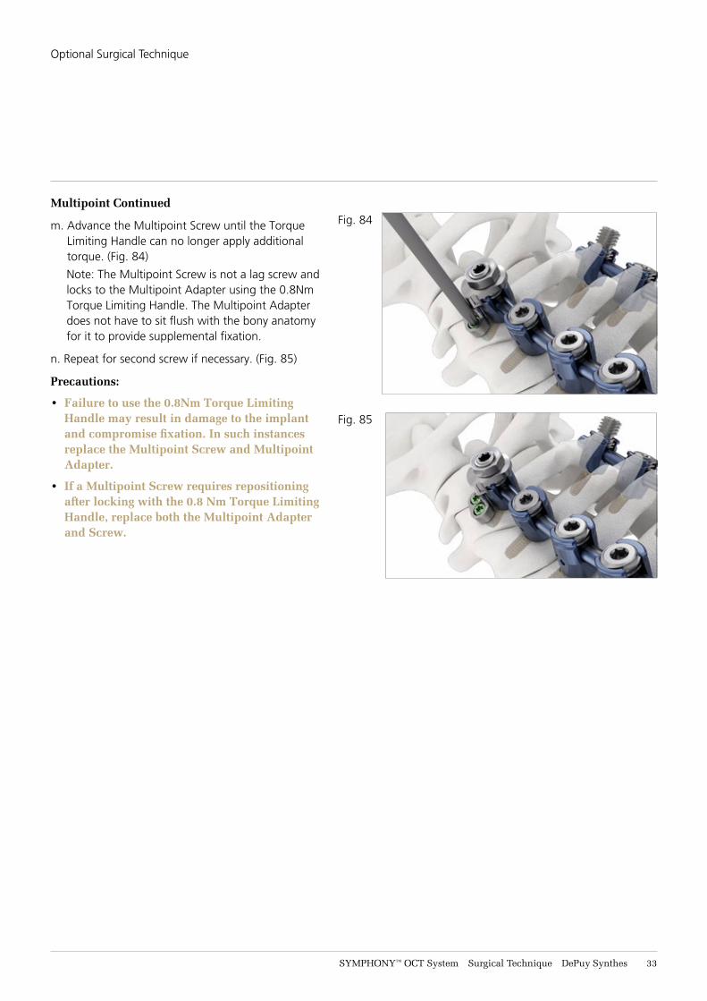
m. Advance the Multipoint Screw until the Torque Limiting Handle can no longer apply additional torque. (Fig. 84)
Note: The Multipoint Screw is not a lag screw and locks to the Multipoint Adapter using the 0.8Nm Torque Limiting Handle. The Multipoint Adapter does not have to sit flush with the bony anatomy for it to provide supplemental fixation.
n. Repeat for second screw if necessary. (Fig. 85)
Precautions:
• Failure to use the 0.8Nm Torque Limiting Handle may result in damage to the implant and compromise fixation. In such instances replace the Multipoint Screw and Multipoint Adapter.
• If a Multipoint Screw requires repositioning after locking with the 0.8 Nm Torque Limiting Handle, replace both the Multipoint Adapter and Screw.
Fig. 84
Fig. 85
Optional Surgical Technique
34 DePuy Synthes SYMPHONY™ OCT System Surgical Technique
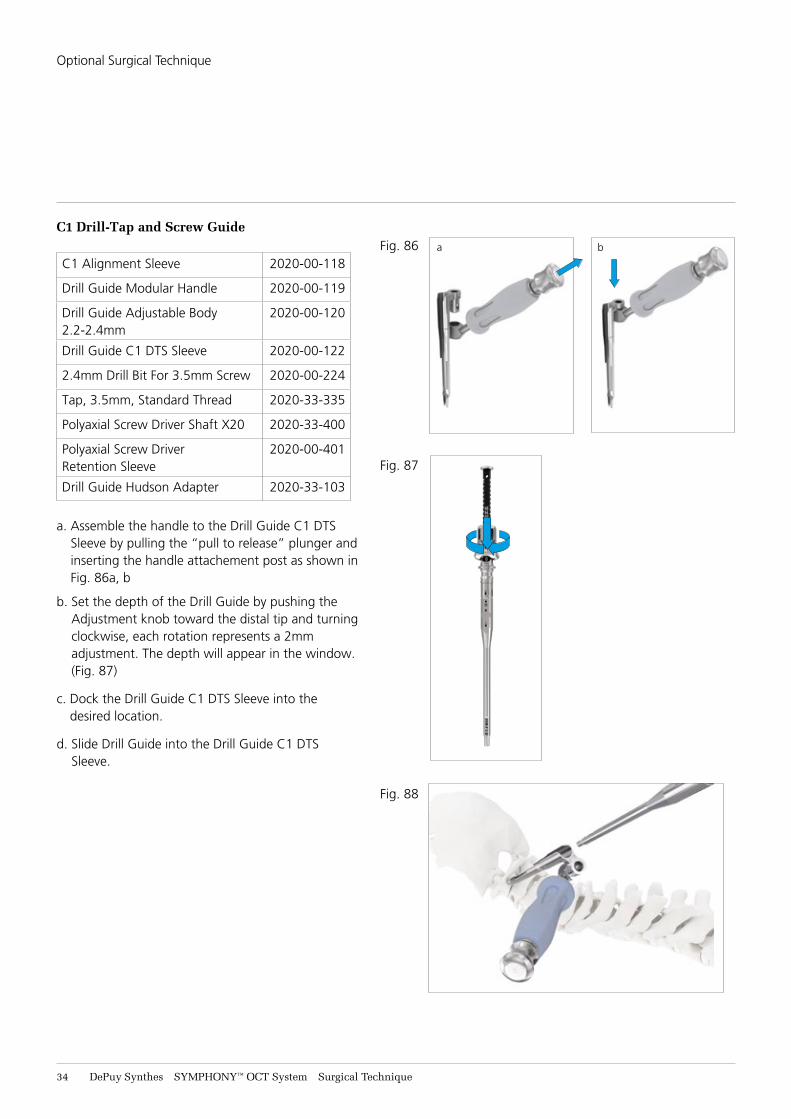
C1 Drill-Tap and Screw Guide
C1 Alignment Sleeve 2020-00-118
Drill Guide Modular Handle 2020-00-119
Drill Guide Adjustable Body 2.2-2.4mm
2020-00-120
Drill Guide C1 DTS Sleeve 2020-00-122
2.4mm Drill Bit For 3.5mm Screw 2020-00-224
Tap, 3.5mm, Standard Thread 2020-33-335
Polyaxial Screw Driver Shaft X20 2020-33-400
Polyaxial Screw Driver Retention Sleeve
2020-00-401
Drill Guide Hudson Adapter 2020-33-103
a. Assemble the handle to the Drill Guide C1 DTS Sleeve by pulling the “pull to release” plunger and inserting the handle attachement post as shown in Fig. 86a, b
b. Set the depth of the Drill Guide by pushing the Adjustment knob toward the distal tip and turning clockwise, each rotation represents a 2mm adjustment. The depth will appear in the window. (Fig. 87)
c. Dock the Drill Guide C1 DTS Sleeve into the desired location.
d. Slide Drill Guide into the Drill Guide C1 DTS Sleeve.
Fig. 86
Fig. 87
Fig. 88
a b
Optional Surgical Technique
SYMPHONY™ OCT System Surgical Technique DePuy Synthes 35
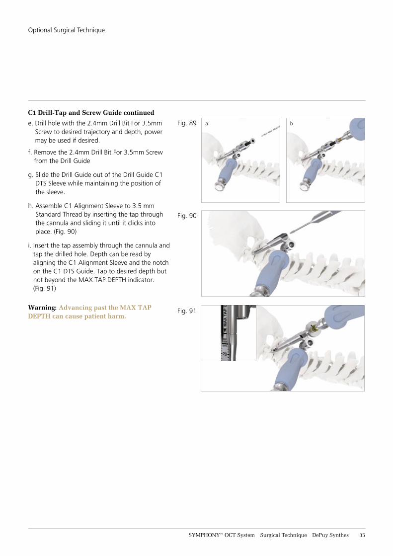
C1 Drill-Tap and Screw Guide continued
e. Drill hole with the 2.4mm Drill Bit For 3.5mm Screw to desired trajectory and depth, power may be used if desired.
f. Remove the 2.4mm Drill Bit For 3.5mm Screw from the Drill Guide
g. Slide the Drill Guide out of the Drill Guide C1 DTS Sleeve while maintaining the position of the sleeve.
h. Assemble C1 Alignment Sleeve to 3.5 mm Standard Thread by inserting the tap through the cannula and sliding it until it clicks into place. (Fig. 90)
i. Insert the tap assembly through the cannula and tap the drilled hole. Depth can be read by aligning the C1 Alignment Sleeve and the notch on the C1 DTS Guide. Tap to desired depth but not beyond the MAX TAP DEPTH indicator. (Fig. 91)
Warning: Advancing past the MAX TAP DEPTH can cause patient harm.
Fig. 89
Fig. 90
Fig. 91
a b
Optional Surgical Technique
36 DePuy Synthes SYMPHONY™ OCT System Surgical Technique
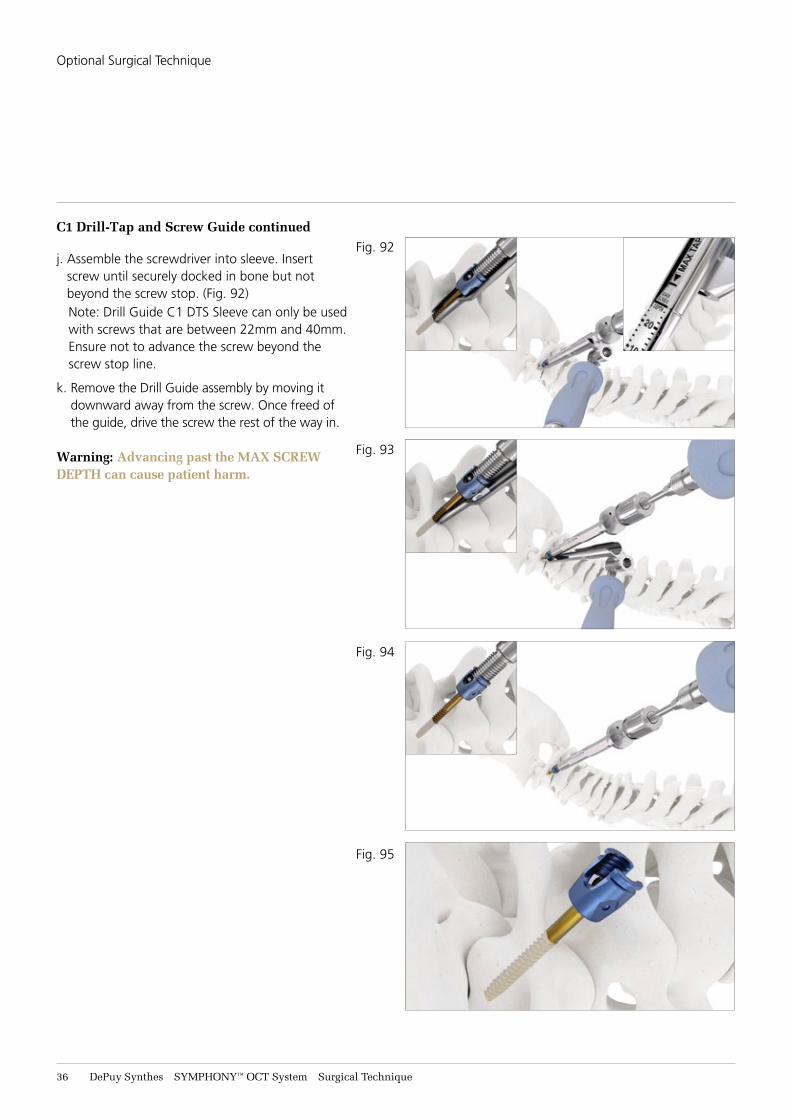
C1 Drill-Tap and Screw Guide continued
j. Assemble the screwdriver into sleeve. Insert screw until securely docked in bone but not beyond the screw stop. (Fig. 92) Note: Drill Guide C1 DTS Sleeve can only be used with screws that are between 22mm and 40mm. Ensure not to advance the screw beyond the screw stop line.
k. Remove the Drill Guide assembly by moving it downward away from the screw. Once freed of the guide, drive the screw the rest of the way in.
Warning: Advancing past the MAX SCREW DEPTH can cause patient harm.
Fig. 92
Fig. 93
Fig. 94
Fig. 95
Optional Surgical Technique

SYMPHONY™ OCT System Surgical Technique DePuy Synthes 37
Lateral Offset Connectors
X15 Self Retaining Set Screw Inserter 2020-00-407
X15 Driver Final Tightener 2020-00-403
AO Handle, Torque Limiting 3.0 Nm 2020-00-504
Counter Torque 2020-00-138
Place the Lateral Offset Connector on the rod. (Fig. 96) Loosely tighten the connector to the rod. Introduce the bar of the Lateral Offset Connector into the polyaxial head of the screw. Insert the set screw using X15 Inserter into the polyaxial head and tighten the set screw of the polyscrew using the X15 Final Tightener Set Screw Inserter and AO Handle, Torque Limiting 3.0 Nm.
Counter torquing is achieved by placing the Counter Torque on the adjacent screw head on the same side of the construct. (Fig. 97)
.
Precaution: Failure to use provided 3.0 Nm torque limiting handle when final tightening may lead to set screw back out.
Parallel Connectors
X15 Self Retaining Set Screw Inserter 2020-00-407
X15 Driver Final Tightener 2020-00-403
AO Handle, Torque Limiting 3.0 Nm 2020-00-504
Parallel connectors allow adjacent coupling of two rods of the same or differing diameters. The self-retaining feature of the X15 Self Retaining Set Screw Inserter can aid with insertion. Either side of the connector may be connected first. Tighten the set screw on one side, then connect the remaining rod and tighten the set screws using the X15 Driver Final Tightener and the AO Handle Torque Limiting 3.0 Nm.
Precaution: Failure to use provided 3.0 Nm torque limiting handle when final tightening may lead to set screw back out.
Fig. 96
Fig. 97
Fig. 98
Optional Surgical Technique
38 DePuy Synthes SYMPHONY™ OCT System Surgical Technique
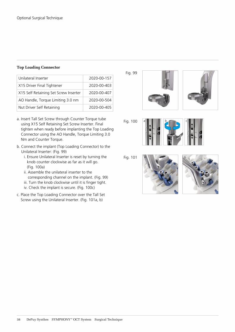
Top Loading Connector
Unilateral Inserter 2020-00-157
X15 Driver Final Tightener 2020-00-403
X15 Self Retaining Set Screw Inserter 2020-00-407
AO Handle, Torque Limiting 3.0 nm 2020-00-504
Nut Driver Self Retaining 2020-00-405
a. Insert Tall Set Screw through Counter Torque tube using X15 Self Retaining Set Screw Inserter. Final tighten when ready before implanting the Top Loading Connector using the AO Handle, Torque Limiting 3.0 Nm and Counter Torque.
b. Connect the implant (Top Loading Connector) to the Unilateral Inserter: (Fig. 99)
i. Ensure Unilateral Inserter is reset by turning the knob counter clockwise as far as it will go. (Fig. 100a)
ii. Assemble the unilateral inserter to the corresponding channel on the implant. (Fig. 99)
iii. Turn the knob clockwise until it is finger tight.iv. Check the implant is secure. (Fig. 100c)
c. Place the Top Loading Connector over the Tall Set Screw using the Unilateral Inserter. (Fig. 101a, b)
Fig. 99
Fig. 100
Fig. 101 a b
a b c
Optional Surgical Technique
SYMPHONY™ OCT System Surgical Technique DePuy Synthes 39
Top Loading Connector continued
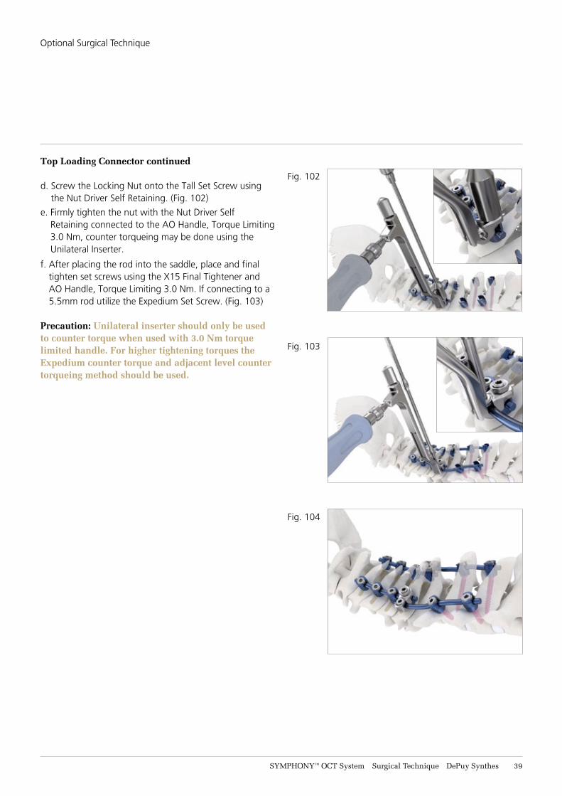
d. Screw the Locking Nut onto the Tall Set Screw using the Nut Driver Self Retaining. (Fig. 102)
e. Firmly tighten the nut with the Nut Driver Self Retaining connected to the AO Handle, Torque Limiting 3.0 Nm, counter torqueing may be done using the Unilateral Inserter.
f. After placing the rod into the saddle, place and final tighten set screws using the X15 Final Tightener and AO Handle, Torque Limiting 3.0 Nm. If connecting to a 5.5mm rod utilize the Expedium Set Screw. (Fig. 103)
Precaution: Unilateral inserter should only be used to counter torque when used with 3.0 Nm torque limited handle. For higher tightening torques the Expedium counter torque and adjacent level counter torqueing method should be used.
Fig. 102
Fig. 103
Fig. 104
Optional Surgical Technique
41 DePuy Synthes SYMPHONY™ OCT System Surgical Technique
Reduction Connector
Unilateral Inserter 2020-00-157
X15 Driver Final Tightener 2020-00-403
AO Handle, Torque Limiting 3.0 nm 2020-00-504
Reduction Tab Breaker 2020-00-154
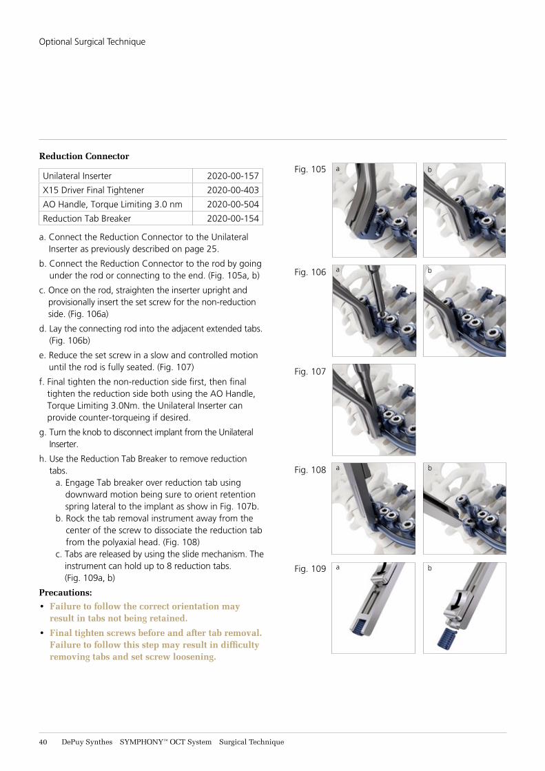
a. Connect the Reduction Connector to the Unilateral Inserter as previously described on page 25.
b. Connect the Reduction Connector to the rod by going under the rod or connecting to the end. (Fig. 105a, b)
c. Once on the rod, straighten the inserter upright and provisionally insert the set screw for the non-reduction side. (Fig. 106a)
d. Lay the connecting rod into the adjacent extended tabs. (Fig. 106b)
e. Reduce the set screw in a slow and controlled motion until the rod is fully seated. (Fig. 107)
f. Final tighten the non-reduction side first, then final tighten the reduction side both using the AO Handle, Torque Limiting 3.0Nm. the Unilateral Inserter can provide counter-torqueing if desired.
g. Turn the knob to disconnect implant from the Unilateral Inserter.
h. Use the Reduction Tab Breaker to remove reduction tabs.
a. Engage Tab breaker over reduction tab using downward motion being sure to orient retention spring lateral to the implant as show in Fig. 107b.
b. Rock the tab removal instrument away from the center of the screw to dissociate the reduction tab from the polyaxial head. (Fig. 108)
c. Tabs are released by using the slide mechanism. The instrument can hold up to 8 reduction tabs. (Fig. 109a, b)
Precautions: • Failure to follow the correct orientation may
result in tabs not being retained.
• Final tighten screws before and after tab removal. Failure to follow this step may result in difficulty removing tabs and set screw loosening.
Fig. 105
Fig. 106
Fig. 107
Fig. 108
Fig. 109
a
a
a
a
b
b
b
b
Optional Surgical Technique
SYMPHONY™ OCT System Surgical Technique DePuy Synthes 41
Reduction Connector continued
i. Once the tabs have been removed, once again fully tighten all locking screws with X15 Driver Final Tightener, the Counter Torque, and the AO Handle, Torque Limiting 3.0 Nm. If connecting to a 5.5mm rod utilize the Expedium Set Screw.
Precaution: For higher tightening torques the Expedium Counter Torque and adjacent level counter torqueing method should be used.
Axial Connectors
X15 Self Retaining Set Screw Inserter 2020-00-407
X15 Driver Final Tightener 2020-00-403
AO Handle, Torque Limiting 3.0 Nm 2020-00-504
Counter Torque 2020-00-138
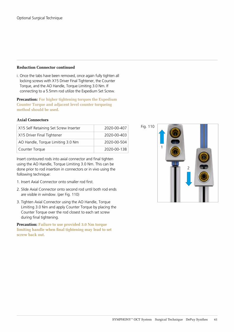
Insert contoured rods into axial connector and final tighten using the AO Handle, Torque Limiting 3.0 Nm. This can be done prior to rod insertion in connectors or in vivo using the following technique:
1. Insert Axial Connector onto smaller rod first.
2. Slide Axial Connector onto second rod until both rod ends are visible in window. (per Fig. 110)
3. Tighten Axial Connector using the AO Handle, Torque Limiting 3.0 Nm and apply Counter Torque by placing the Counter Torque over the rod closest to each set screw during final tightening.
Precaution: Failure to use provided 3.0 Nm torque limiting handle when final tightening may lead to set screw back out.
2
1
Fig. 110
Optional Surgical Technique
42 DePuy Synthes SYMPHONY™ OCT System Surgical Technique
Cable Connector
X15 Self Retaining Set Screw Inserter 2020-00-407
X15 Driver Final Tightener 2020-00-403
AO Handle, Torque Limiting 3.0 Nm 2020-00-504
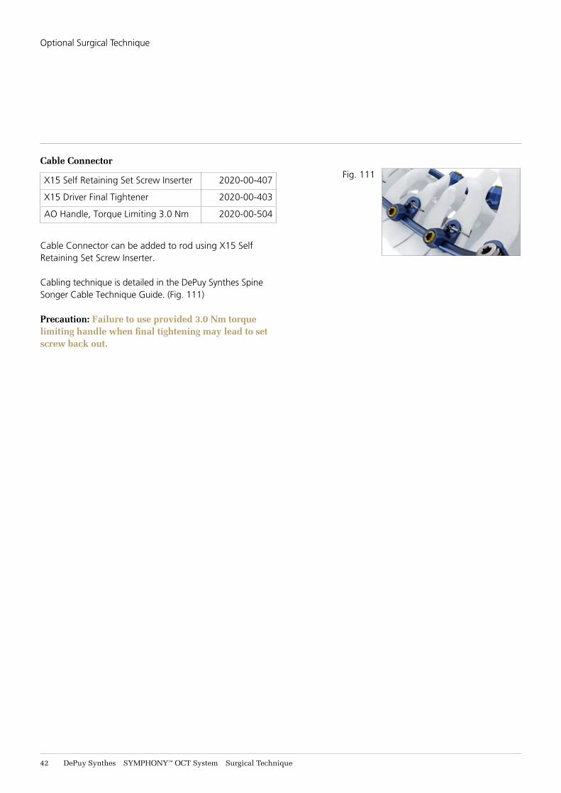
Cable Connector can be added to rod using X15 Self Retaining Set Screw Inserter.
Cabling technique is detailed in the DePuy Synthes Spine Songer Cable Technique Guide. (Fig. 111)
Precaution: Failure to use provided 3.0 Nm torque limiting handle when final tightening may lead to set screw back out.
Fig. 111
Optional Surgical Technique
SYMPHONY™ OCT System Surgical Technique DePuy Synthes 43
Fig. 111
Fig. 112
Fig. 113
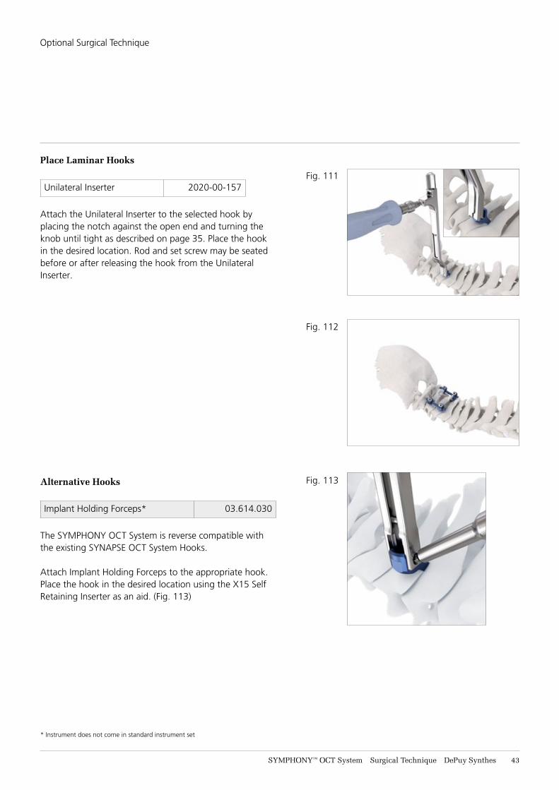
Unilateral Inserter 2020-00-157
Attach the Unilateral Inserter to the selected hook by placing the notch against the open end and turning the knob until tight as described on page 35. Place the hook in the desired location. Rod and set screw may be seated before or after releasing the hook from the Unilateral Inserter.
Alternative Hooks
Implant Holding Forceps* 03.614.030
The SYMPHONY OCT System is reverse compatible with the existing SYNAPSE OCT System Hooks.
Attach Implant Holding Forceps to the appropriate hook. Place the hook in the desired location using the X15 Self Retaining Inserter as an aid. (Fig. 113)
Place Laminar Hooks
Optional Surgical Technique
* Instrument does not come in standard instrument set

44 DePuy Synthes SYMPHONY™ OCT System Surgical Technique
Implant Removal Instructions:
If the decision is made to remove implants the following steps should be taken after the implant is exposed.
For set screw and rod, clean debris from set screw and lower the Counter Torque over the screw head. Insert the X15 into the Counter Torque and engage the set screw. Turn handle counterclockwise to loosen the set screws. Use Kerrison or tower to maintain rod position until set screw is removed and slowly release. Once the set screws are removed the rods can then be removed.
All SYMPHONY OCT System Bone Screws can be removed with an X20 screwdriver. Once the rods are removed, align the polyaxial head to allow access to drive feature and engage the X20. Turn counterclockwise to remove the screw.
All other implants are removed using an X15 screwdriver.
Top Loading Cross Connectors, Top Loading Connectors and Multipoint Implant require the use of the Nut Driver for removal.
Multipoint Implant screws are removed with a T8 screwdriver.
Optional Surgical Technique
SYMPHONY™ OCT System Surgical Technique DePuy Synthes 45
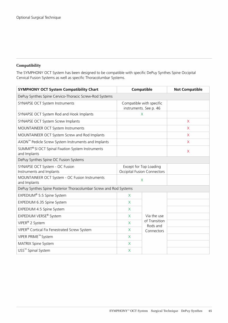
Compatibility
The SYMPHONY OCT System has been designed to be compatible with specific DePuy Synthes Spine Occipital Cervical Fusion Systems as well as specific Thoracolumbar Systems.
SYMPHONY OCT System Compatibility Chart Compatible Not Compatible
DePuy Synthes Spine Cervico-Thoracic Screw-Rod Systems
SYNAPSE OCT System Instruments Compatible with specific instruments. See p. 46
SYNAPSE OCT System Rod and Hook Implants X
SYNAPSE OCT System Screw Implants X
MOUNTAINEER OCT System Instruments X
MOUNTAINEER OCT System Screw and Rod Implants X
AXON™ Pedicle Screw System Instruments and Implants X
SUMMIT® SI OCT Spinal Fixation System Instruments and Implants
X
DePuy Synthes Spine OC Fusion Systems
SYNAPSE OCT System - OC Fusion Instruments and Implants
Except for Top Loading Occipital Fusion Connectors
MOUNTAINEER OCT System - OC Fusion Instruments and Implants
X
DePuy Synthes Spine Posterior Thoracolumbar Screw and Rod Systems
EXPEDIUM® 5.5 Spine System X
Via the use of Transition
Rods and Connectors
EXPEDIUM 6.35 Spine System X
EXPEDIUM 4.5 Spine System X
EXPEDIUM VERSE® System X
VIPER® 2 System X
VIPER® Cortical Fix Fenestrated Screw System X
VIPER PRIME™ System X
MATRIX Spine System X
USS™ Spinal System X
Optional Surgical Technique
46 DePuy Synthes SYMPHONY™ OCT System Surgical Technique
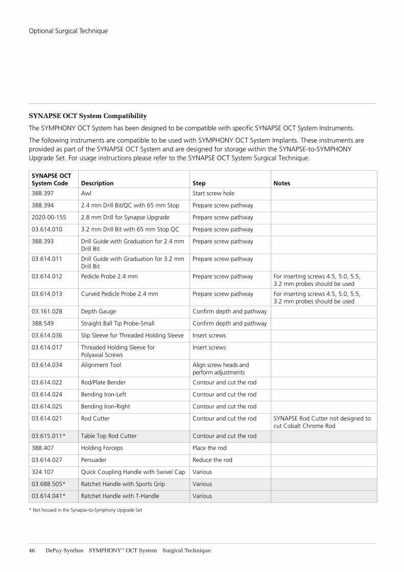
SYNAPSE OCT System Compatibility
The SYMPHONY OCT System has been designed to be compatible with specific SYNAPSE OCT System Instruments.
The following instruments are compatible to be used with SYMPHONY OCT System Implants. These instruments are provided as part of the SYNAPSE OCT System and are designed for storage within the SYNAPSE-to-SYMPHONY Upgrade Set. For usage instructions please refer to the SYNAPSE OCT System Surgical Technique.
SYNAPSE OCT System Code Description Step Notes
388.397 Awl Start screw hole
388.394 2.4 mm Drill Bit/QC with 65 mm Stop Prepare screw pathway
2020-00-155 2.8 mm Drill for Synapse Upgrade Prepare screw pathway
03.614.010 3.2 mm Drill Bit with 65 mm Stop QC Prepare screw pathway
388.393 Drill Guide with Graduation for 2.4 mm Drill Bit
Prepare screw pathway
03.614.011 Drill Guide with Graduation for 3.2 mm Drill Bit
Prepare screw pathway
03.614.012 Pedicle Probe 2.4 mm Prepare screw pathway For inserting screws 4.5, 5.0, 5.5, 3.2 mm probes should be used
03.614.013 Curved Pedicle Probe 2.4 mm Prepare screw pathway For inserting screws 4.5, 5.0, 5.5, 3.2 mm probes should be used
03.161.028 Depth Gauge Confirm depth and pathway
388.549 Straight Ball Tip Probe-Small Confirm depth and pathway
03.614.036 Slip Sleeve for Threaded Holding Sleeve Insert screws
03.614.017 Threaded Holding Sleeve for Polyaxial Screws
Insert screws
03.614.034 Alignment Tool Align screw heads and perform adjustments
03.614.022 Rod/Plate Bender Contour and cut the rod
03.614.024 Bending Iron-Left Contour and cut the rod
03.614.025 Bending Iron-Right Contour and cut the rod
03.614.021 Rod Cutter Contour and cut the rod SYNAPSE Rod Cutter not designed to cut Cobalt Chrome Rod
03.615.011* Table Top Rod Cutter Contour and cut the rod
388.407 Holding Forceps Place the rod
03.614.027 Persuader Reduce the rod
324.107 Quick Coupling Handle with Swivel Cap Various
03.688.505* Ratchet Handle with Sports Grip Various
03.614.041* Ratchet Handle with T-Handle Various
* Not housed in the Synapse-to-Symphony Upgrade Set
Optional Surgical Technique
SYMPHONY™ OCT System Surgical Technique DePuy Synthes 47
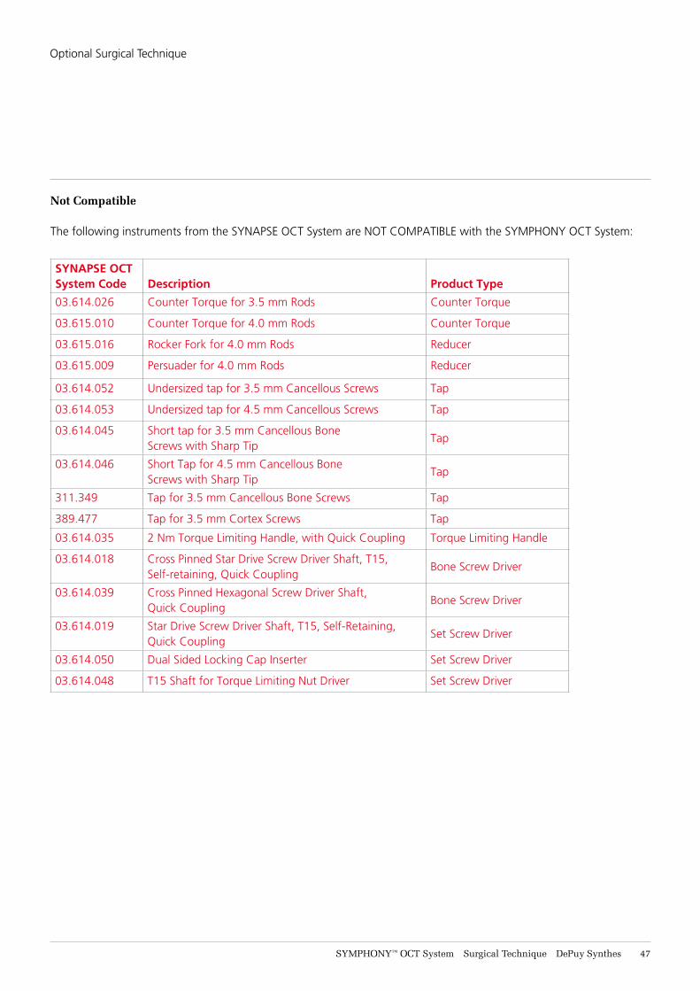
Not Compatible
The following instruments from the SYNAPSE OCT System are NOT COMPATIBLE with the SYMPHONY OCT System:
SYNAPSE OCT System Code Description Product Type
03.614.026 Counter Torque for 3.5 mm Rods Counter Torque
03.615.010 Counter Torque for 4.0 mm Rods Counter Torque
03.615.016 Rocker Fork for 4.0 mm Rods Reducer
03.615.009 Persuader for 4.0 mm Rods Reducer
03.614.052 Undersized tap for 3.5 mm Cancellous Screws Tap
03.614.053 Undersized tap for 4.5 mm Cancellous Screws Tap
03.614.045 Short tap for 3.5 mm Cancellous BoneScrews with Sharp Tip
Tap
03.614.046 Short Tap for 4.5 mm Cancellous BoneScrews with Sharp Tip
Tap
311.349 Tap for 3.5 mm Cancellous Bone Screws Tap
389.477 Tap for 3.5 mm Cortex Screws Tap
03.614.035 2 Nm Torque Limiting Handle, with Quick Coupling Torque Limiting Handle
03.614.018 Cross Pinned Star Drive Screw Driver Shaft, T15, Self-retaining, Quick Coupling
Bone Screw Driver
03.614.039 Cross Pinned Hexagonal Screw Driver Shaft, Quick Coupling
Bone Screw Driver
03.614.019 Star Drive Screw Driver Shaft, T15, Self-Retaining, Quick Coupling
Set Screw Driver
03.614.050 Dual Sided Locking Cap Inserter Set Screw Driver
03.614.048 T15 Shaft for Torque Limiting Nut Driver Set Screw Driver
Optional Surgical Technique
48 DePuy Synthes SYMPHONY™ OCT System Surgical Technique
Occipital Cervical Fusion
SYNAPSE OCT System
The DePuy Synthes Spine SYMPHONY OCT System is compatible with additionally available implants and instruments that are intended to provide immobilization and stabilization as an adjunct to fusion of the occipitocervical junction. The OC Fusion System includes a complete set of implants and instruments designed to optimize fixation to the occiput and connect with DePuy Synthes Spine Cervical and Thoracic Systems.
Features
The OC Fusion System offers the surgeon several implant options for the occiput. The instrumentation is designed to accommodate mid-line exposures and varying patient anatomy.
Preparation
Required Sets
Occipital Cervical Fusion Instrument and Titanium Implant Set
And
SYMPHONY Core Instrument Set
With either
SYMPHONY Core 3.5/4.0 Implant Set
or
SYMPHONY Core 3.5 Only Implant Setdependent on onsite preference / availability
SYMPHONY™ OCT System Surgical Technique DePuy Synthes 49
Occipital Cervical Fusion
Preoperative Planning1ImagingAll necessary imaging studies should be available to plan occipital screw placement and accommodate anatomic variations in individual patient anatomy.
2Position PatientPatient positioning is critical for occipitocervical fusion procedures. The patient should be placed on the operating table in the prone position with the patient’s head securely immobilized. Confirm proper patient position by direct visualization and reconciliation with radiographs before draping.
3ApproachMake a standard midline incision from the external occipital protuberance and continue caudally, and then expose the posterior bony elements sufficiently to allow placement of instrumentation as well as preferred graft material in and around the decorticated posterior elements.
51 DePuy Synthes SYMPHONY™ OCT System Surgical Technique
Occipital Cervical Fusion
Step 1Attach Bone Anchors
Attach bone anchors to the cervical and/or thoracic spine as described in the DePuy Synthes Spine SYMPHONY OCT System as needed.
Step 2Select Occipital Plate
03.161.0xx Template, for Occipital Plate
387.689 Plate Holder
Select a template of the plate style and size estimated to best fit the occiput. Contour the template to fit the anatomy. (Fig. 114)
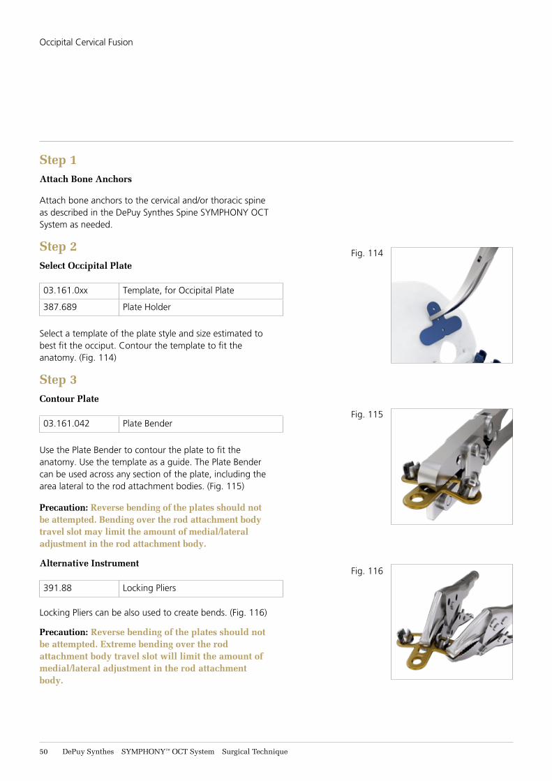
Step 3Contour Plate
03.161.042 Plate Bender
Use the Plate Bender to contour the plate to fit the anatomy. Use the template as a guide. The Plate Bender can be used across any section of the plate, including the area lateral to the rod attachment bodies. (Fig. 115)
Precaution: Reverse bending of the plates should not be attempted. Bending over the rod attachment body travel slot may limit the amount of medial/lateral adjustment in the rod attachment body.
Alternative Instrument
391.88 Locking Pliers
Locking Pliers can be also used to create bends. (Fig. 116)
Precaution: Reverse bending of the plates should not be attempted. Extreme bending over the rod attachment body travel slot will limit the amount of medial/lateral adjustment in the rod attachment body.
Fig. 114
Fig. 115
Fig. 116
SYMPHONY™ OCT System Surgical Technique DePuy Synthes 51
Occipital Cervical Fusion
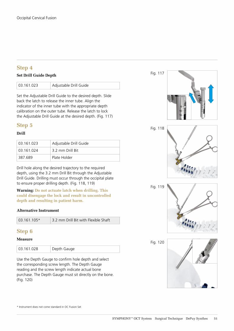
Step 4Set Drill Guide Depth
03.161.023 Adjustable Drill Guide
Set the Adjustable Drill Guide to the desired depth. Slide back the latch to release the inner tube. Align the indicator of the inner tube with the appropriate depth calibration on the outer tube. Release the latch to lock the Adjustable Drill Guide at the desired depth. (Fig. 117)
Step 5Drill
03.161.023 Adjustable Drill Guide
03.161.024 3.2 mm Drill Bit
387.689 Plate Holder
Drill hole along the desired trajectory to the required depth, using the 3.2 mm Drill Bit through the Adjustable Drill Guide. Drilling must occur through the occipital plate to ensure proper drilling depth. (Fig. 118, 119)
Warning: Do not actuate latch when drilling. This could disengage the lock and result in uncontrolled depth and resulting in patient harm.
Alternative Instrument
03.161.105* 3.2 mm Drill Bit with Flexible Shaft
Step 6Measure
03.161.028 Depth Gauge
Use the Depth Gauge to confirm hole depth and select the corresponding screw length. The Depth Gauge reading and the screw length indicate actual bone purchase. The Depth Gauge must sit directly on the bone. (Fig. 120)
* Instrument does not come standard in OC Fusion Set
Fig. 117
Fig. 118
Fig. 119
Fig. 120
52 DePuy Synthes SYMPHONY™ OCT System Surgical Technique
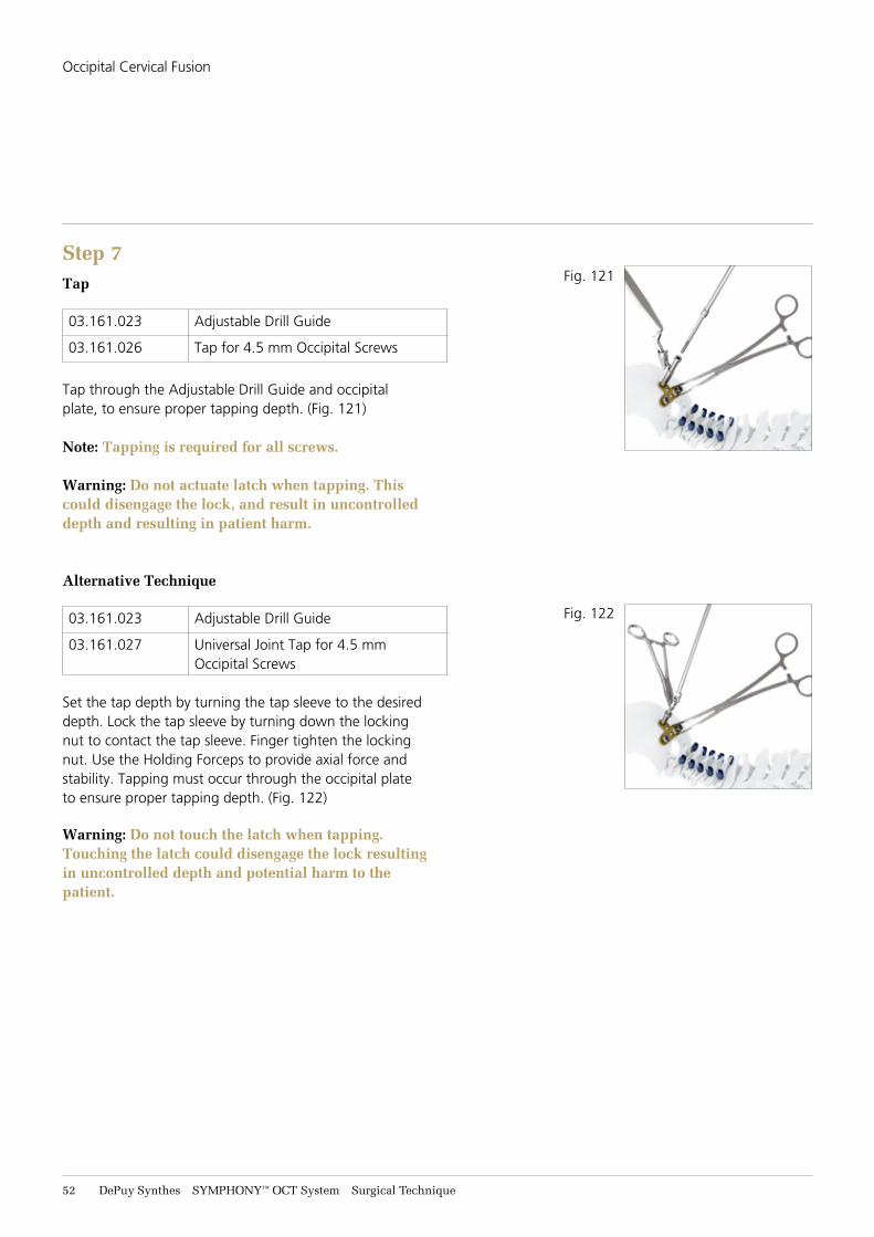
Step 7Tap
03.161.023 Adjustable Drill Guide
03.161.026 Tap for 4.5 mm Occipital Screws
Tap through the Adjustable Drill Guide and occipital plate, to ensure proper tapping depth. (Fig. 121)
Note: Tapping is required for all screws.
Warning: Do not actuate latch when tapping. This could disengage the lock, and result in uncontrolled depth and resulting in patient harm.
Alternative Technique
03.161.023 Adjustable Drill Guide
03.161.027 Universal Joint Tap for 4.5 mm Occipital Screws
Set the tap depth by turning the tap sleeve to the desired depth. Lock the tap sleeve by turning down the locking nut to contact the tap sleeve. Finger tighten the locking nut. Use the Holding Forceps to provide axial force and stability. Tapping must occur through the occipital plate to ensure proper tapping depth. (Fig. 122)
Warning: Do not touch the latch when tapping. Touching the latch could disengage the lock resulting in uncontrolled depth and potential harm to the patient.
Fig. 121
Fig. 122
Occipital Cervical Fusion
SYMPHONY™ OCT System Surgical Technique DePuy Synthes 53
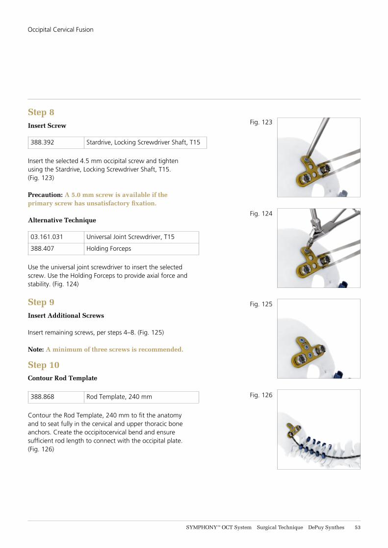
Step 8Insert Screw
388.392 Stardrive, Locking Screwdriver Shaft, T15
Insert the selected 4.5 mm occipital screw and tighten using the Stardrive, Locking Screwdriver Shaft, T15. (Fig. 123)
Precaution: A 5.0 mm screw is available if the primary screw has unsatisfactory fixation.
Alternative Technique
03.161.031 Universal Joint Screwdriver, T15
388.407 Holding Forceps
Use the universal joint screwdriver to insert the selected screw. Use the Holding Forceps to provide axial force and stability. (Fig. 124)
Step 9Insert Additional Screws
Insert remaining screws, per steps 4–8. (Fig. 125)
Note: A minimum of three screws is recommended.
Step 10Contour Rod Template
388.868 Rod Template, 240 mm
Contour the Rod Template, 240 mm to fit the anatomy and to seat fully in the cervical and upper thoracic bone anchors. Create the occipitocervical bend and ensure sufficient rod length to connect with the occipital plate. (Fig. 126)
Fig. 123
Fig. 124
Fig. 125
Fig. 126
Occipital Cervical Fusion
54 DePuy Synthes SYMPHONY™ OCT System Surgical Technique
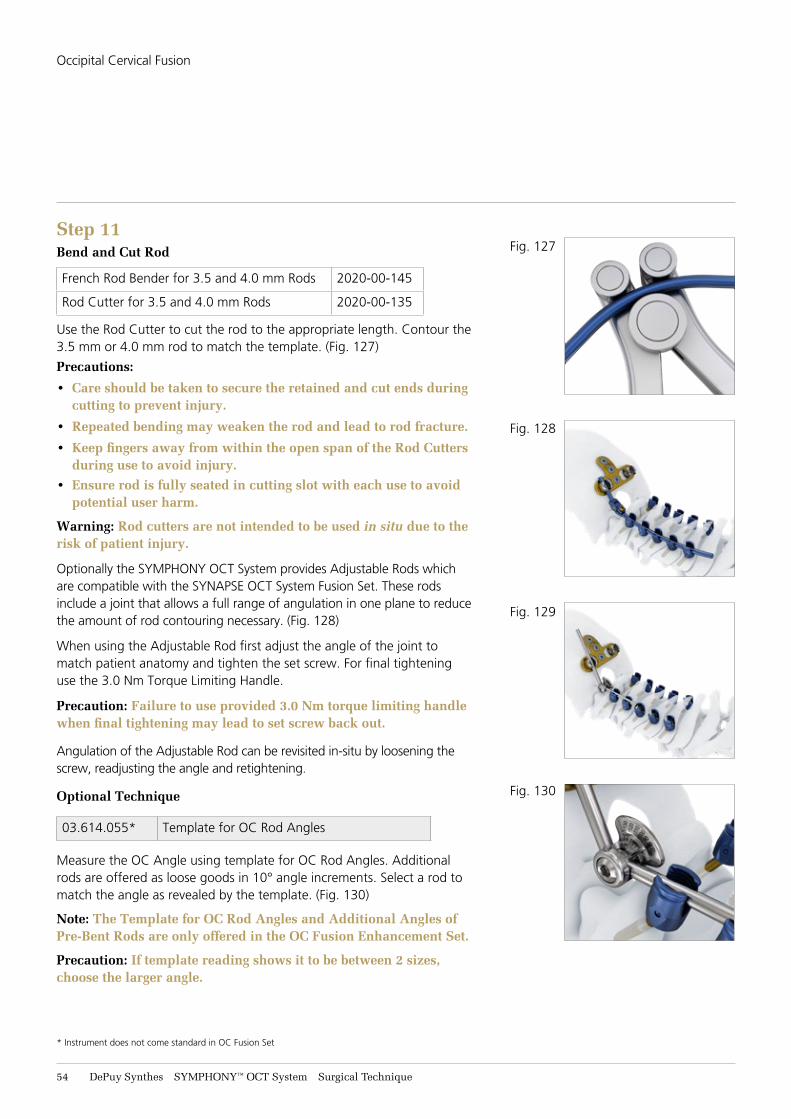
Step 11Bend and Cut Rod
French Rod Bender for 3.5 and 4.0 mm Rods 2020-00-145
Rod Cutter for 3.5 and 4.0 mm Rods 2020-00-135
Use the Rod Cutter to cut the rod to the appropriate length. Contour the 3.5 mm or 4.0 mm rod to match the template. (Fig. 127)
Precautions:
• Care should be taken to secure the retained and cut ends during cutting to prevent injury.
• Repeated bending may weaken the rod and lead to rod fracture.
• Keep fingers away from within the open span of the Rod Cutters during use to avoid injury.
• Ensure rod is fully seated in cutting slot with each use to avoid potential user harm.
Warning: Rod cutters are not intended to be used in situ due to the risk of patient injury.
Optionally the SYMPHONY OCT System provides Adjustable Rods which are compatible with the SYNAPSE OCT System Fusion Set. These rods include a joint that allows a full range of angulation in one plane to reduce the amount of rod contouring necessary. (Fig. 128)
When using the Adjustable Rod first adjust the angle of the joint to match patient anatomy and tighten the set screw. For final tightening use the 3.0 Nm Torque Limiting Handle.
Precaution: Failure to use provided 3.0 Nm torque limiting handle when final tightening may lead to set screw back out.
Angulation of the Adjustable Rod can be revisited in-situ by loosening the screw, readjusting the angle and retightening.
Optional Technique
03.614.055* Template for OC Rod Angles
Measure the OC Angle using template for OC Rod Angles. Additional rods are offered as loose goods in 10° angle increments. Select a rod to match the angle as revealed by the template. (Fig. 130)
Note: The Template for OC Rod Angles and Additional Angles of Pre-Bent Rods are only offered in the OC Fusion Enhancement Set.
Precaution: If template reading shows it to be between 2 sizes, choose the larger angle.
* Instrument does not come standard in OC Fusion Set
Fig. 127
Fig. 128
Fig. 129
Fig. 130
Occipital Cervical Fusion
SYMPHONY™ OCT System Surgical Technique DePuy Synthes 55
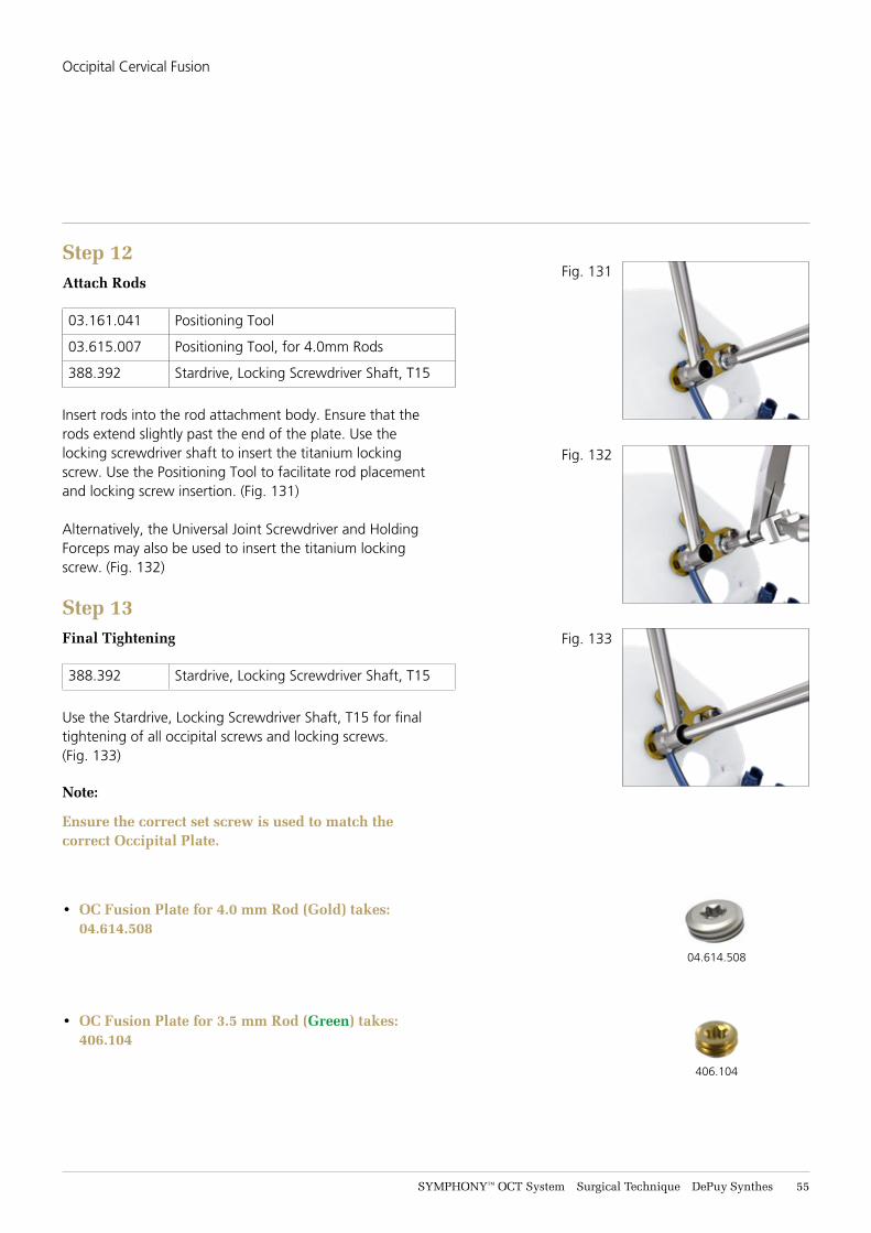
Step 12Attach Rods
03.161.041 Positioning Tool
03.615.007 Positioning Tool, for 4.0mm Rods
388.392 Stardrive, Locking Screwdriver Shaft, T15
Insert rods into the rod attachment body. Ensure that the rods extend slightly past the end of the plate. Use the locking screwdriver shaft to insert the titanium locking screw. Use the Positioning Tool to facilitate rod placement and locking screw insertion. (Fig. 131)
Alternatively, the Universal Joint Screwdriver and Holding Forceps may also be used to insert the titanium locking screw. (Fig. 132)
Step 13Final Tightening
388.392 Stardrive, Locking Screwdriver Shaft, T15
Use the Stardrive, Locking Screwdriver Shaft, T15 for final tightening of all occipital screws and locking screws. (Fig. 133)
Note:
Ensure the correct set screw is used to match the correct Occipital Plate.
• OC Fusion Plate for 4.0 mm Rod (Gold) takes: 04.614.508
• OC Fusion Plate for 3.5 mm Rod (Green) takes: 406.104
Fig. 131
Fig. 132
Fig. 133
04.614.508
406.104
Occipital Cervical Fusion
56 DePuy Synthes SYMPHONY™ OCT System Surgical Technique
Occipital Clamps
Step 1Attach Bone Anchors
Attach bone anchors to the cervical and thoracic spine as described in the DePuy Synthes Spine SYMPHONY OCT System.
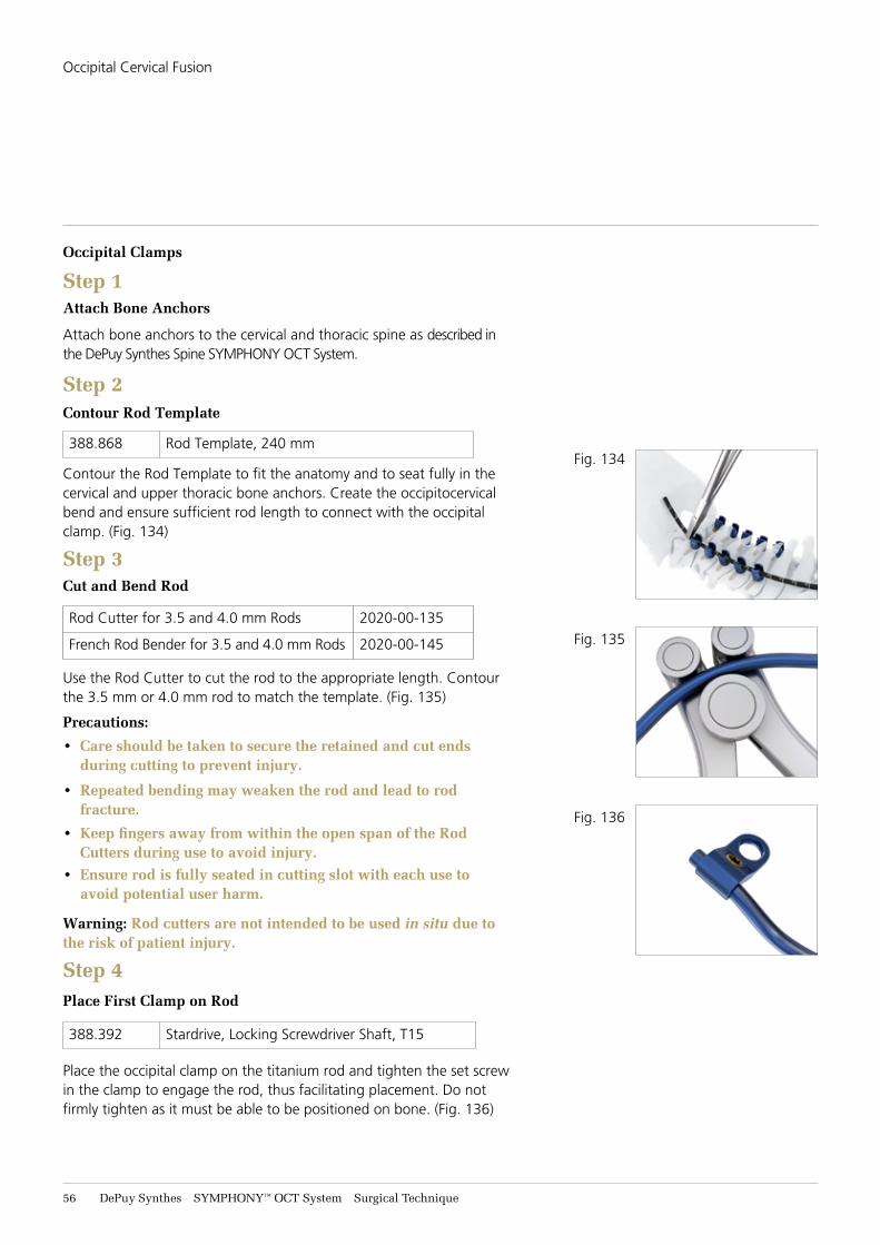
Step 2Contour Rod Template
388.868 Rod Template, 240 mm
Contour the Rod Template to fit the anatomy and to seat fully in the cervical and upper thoracic bone anchors. Create the occipitocervical bend and ensure sufficient rod length to connect with the occipital clamp. (Fig. 134)
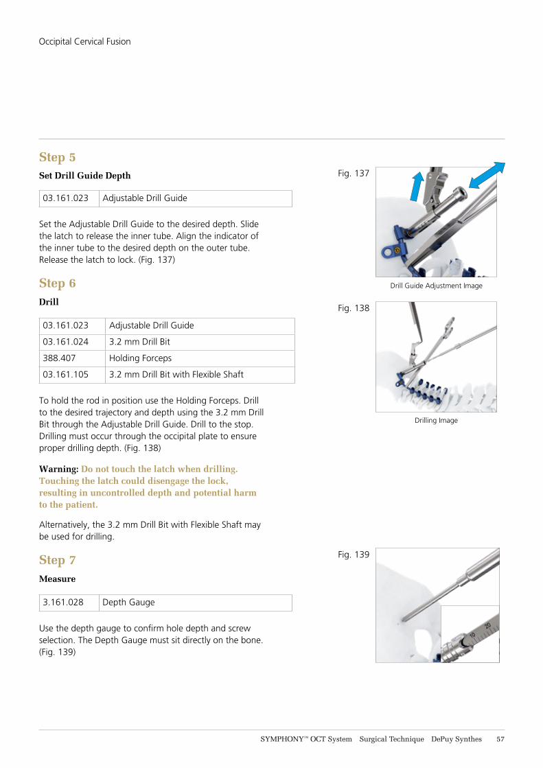
Step 3Cut and Bend Rod
Rod Cutter for 3.5 and 4.0 mm Rods 2020-00-135
French Rod Bender for 3.5 and 4.0 mm Rods 2020-00-145
Use the Rod Cutter to cut the rod to the appropriate length. Contour the 3.5 mm or 4.0 mm rod to match the template. (Fig. 135)
Precautions:
• Care should be taken to secure the retained and cut ends during cutting to prevent injury.
• Repeated bending may weaken the rod and lead to rod fracture.
• Keep fingers away from within the open span of the Rod Cutters during use to avoid injury.
• Ensure rod is fully seated in cutting slot with each use to avoid potential user harm.
Warning: Rod cutters are not intended to be used in situ due to the risk of patient injury.
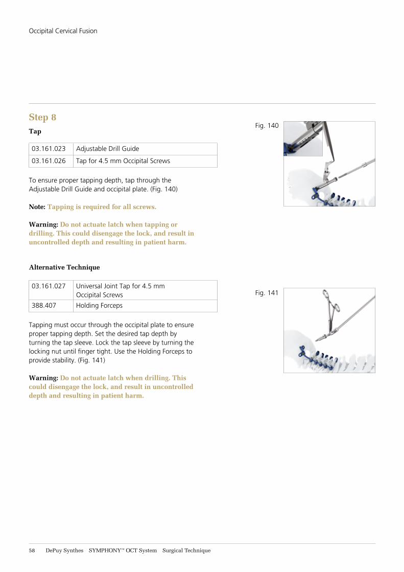
Step 4Place First Clamp on Rod
388.392 Stardrive, Locking Screwdriver Shaft, T15
Place the occipital clamp on the titanium rod and tighten the set screw in the clamp to engage the rod, thus facilitating placement. Do not firmly tighten as it must be able to be positioned on bone. (Fig. 136)
Fig. 134
Fig. 135
Fig. 136
Occipital Cervical Fusion
SYMPHONY™ OCT System Surgical Technique DePuy Synthes 57
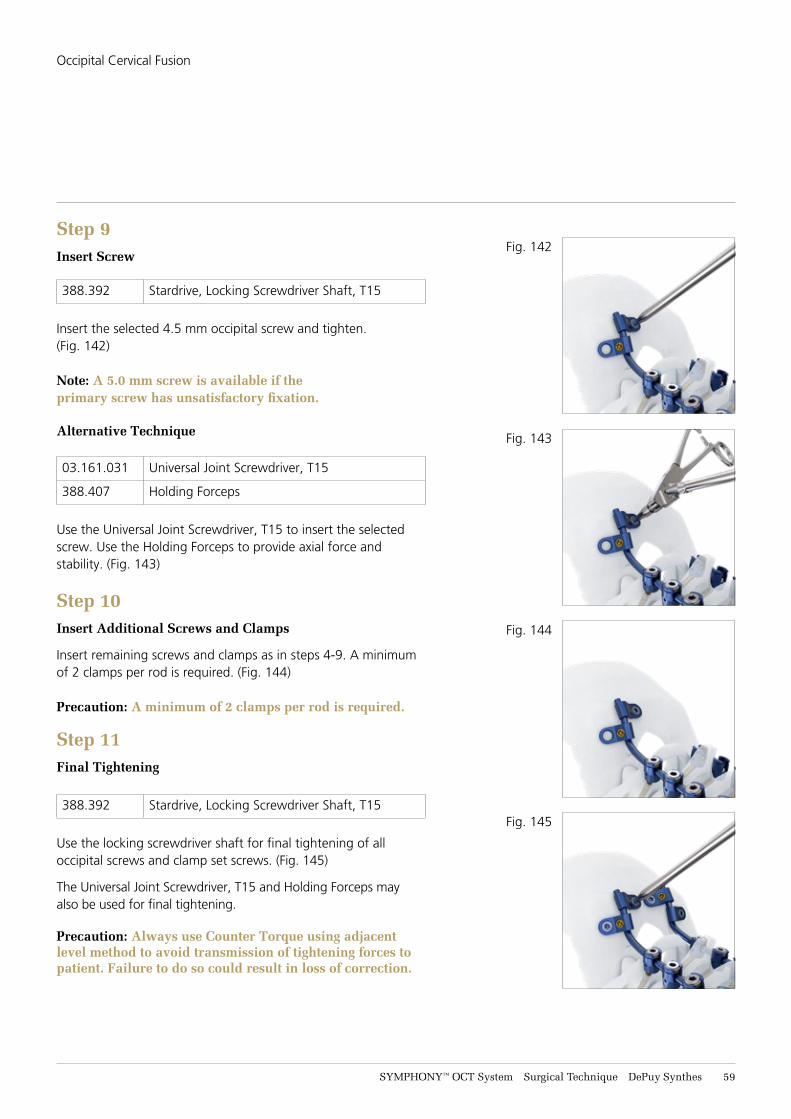
Step 5Set Drill Guide Depth
03.161.023 Adjustable Drill Guide
Set the Adjustable Drill Guide to the desired depth. Slide the latch to release the inner tube. Align the indicator of the inner tube to the desired depth on the outer tube. Release the latch to lock. (Fig. 137)
Step 6Drill
03.161.023 Adjustable Drill Guide
03.161.024 3.2 mm Drill Bit
388.407 Holding Forceps
03.161.105 3.2 mm Drill Bit with Flexible Shaft
To hold the rod in position use the Holding Forceps. Drill to the desired trajectory and depth using the 3.2 mm Drill Bit through the Adjustable Drill Guide. Drill to the stop. Drilling must occur through the occipital plate to ensure proper drilling depth. (Fig. 138)
Warning: Do not touch the latch when drilling. Touching the latch could disengage the lock, resulting in uncontrolled depth and potential harm to the patient.
Alternatively, the 3.2 mm Drill Bit with Flexible Shaft may be used for drilling.
Step 7Measure
3.161.028 Depth Gauge
Use the depth gauge to confirm hole depth and screw selection. The Depth Gauge must sit directly on the bone. (Fig. 139)
Fig. 137
Fig. 138
Fig. 139
Drill Guide Adjustment Image
Drilling Image
Occipital Cervical Fusion
58 DePuy Synthes SYMPHONY™ OCT System Surgical Technique
Step 8Tap
03.161.023 Adjustable Drill Guide
03.161.026 Tap for 4.5 mm Occipital Screws
To ensure proper tapping depth, tap through the Adjustable Drill Guide and occipital plate. (Fig. 140)
Note: Tapping is required for all screws.
Warning: Do not actuate latch when tapping or drilling. This could disengage the lock, and result in uncontrolled depth and resulting in patient harm.
Alternative Technique
03.161.027 Universal Joint Tap for 4.5 mm Occipital Screws
388.407 Holding Forceps
Tapping must occur through the occipital plate to ensure proper tapping depth. Set the desired tap depth by turning the tap sleeve. Lock the tap sleeve by turning the locking nut until finger tight. Use the Holding Forceps to provide stability. (Fig. 141)
Warning: Do not actuate latch when drilling. This could disengage the lock, and result in uncontrolled depth and resulting in patient harm.
Fig. 140
Fig. 141
Occipital Cervical Fusion
SYMPHONY™ OCT System Surgical Technique DePuy Synthes 59
Step 9Insert Screw
388.392 Stardrive, Locking Screwdriver Shaft, T15
Insert the selected 4.5 mm occipital screw and tighten. (Fig. 142)
Note: A 5.0 mm screw is available if the primary screw has unsatisfactory fixation.
Alternative Technique
03.161.031 Universal Joint Screwdriver, T15
388.407 Holding Forceps
Use the Universal Joint Screwdriver, T15 to insert the selected screw. Use the Holding Forceps to provide axial force and stability. (Fig. 143)
Step 10Insert Additional Screws and Clamps
Insert remaining screws and clamps as in steps 4-9. A minimum of 2 clamps per rod is required. (Fig. 144)
Precaution: A minimum of 2 clamps per rod is required.
Step 11Final Tightening
388.392 Stardrive, Locking Screwdriver Shaft, T15
Use the locking screwdriver shaft for final tightening of all occipital screws and clamp set screws. (Fig. 145)
The Universal Joint Screwdriver, T15 and Holding Forceps may also be used for final tightening.
Precaution: Always use Counter Torque using adjacent level method to avoid transmission of tightening forces to patient. Failure to do so could result in loss of correction.
Fig. 142
Fig. 143
Fig. 144
Fig. 145
Occipital Cervical Fusion

61 DePuy Synthes SYMPHONY™ OCT System Surgical Technique
Occipital Plate Rod
Step 1Attach Bone Anchors
Attach bone anchors to the cervical and thoracic spine as described in the DePuy Synthes Spine SYMPHONY OCT System.
Step 2Contour Rod Template
03.161.003 Template for Occipital Plate/Rod
Contour the Template for Occipital Plate/Rod to fit the anatomy and to seat fully in the cervical and upper thoracic bone anchors. (Fig. 146)
Step 3Cut and Bend Rod
2020-00-135 Rod Cutter for 3.5 and 4.0 mm Rods
2020-00-145 French Rod Bender for 3.5 and 4.0 mm Rods
Contour the 3.5 mm or 4.0 mm rod to match the template. Use the Rod Cutter to cut the rod to the appropriate length.
Precautions:
• Care should be taken to secure the retained and cut ends during cutting to prevent injury.
• Keep fingers away from within the open span of the Rod Cutters during use to avoid injury
• Ensure rod is fully seated in cutting slot with each use to avoid potential user harm
• Repeated bending may weaken the rod and lead to rod fracture.
Warning: Rod cutters are not intended to be used in situ due to the risk of patient injury.
Step 4Set Drill Guide Depth
03.161.023 Adjustable Drill Guide
Set the Adjustable Drill Guide to the desired depth by sliding back the latch to release the inner tube. Align the indicator of the inner tube with the appropriate depth marking on the outer tube. Release the latch to lock the drill guide.
Fig. 146
Occipital Cervical Fusion
SYMPHONY™ OCT System Surgical Technique DePuy Synthes 61
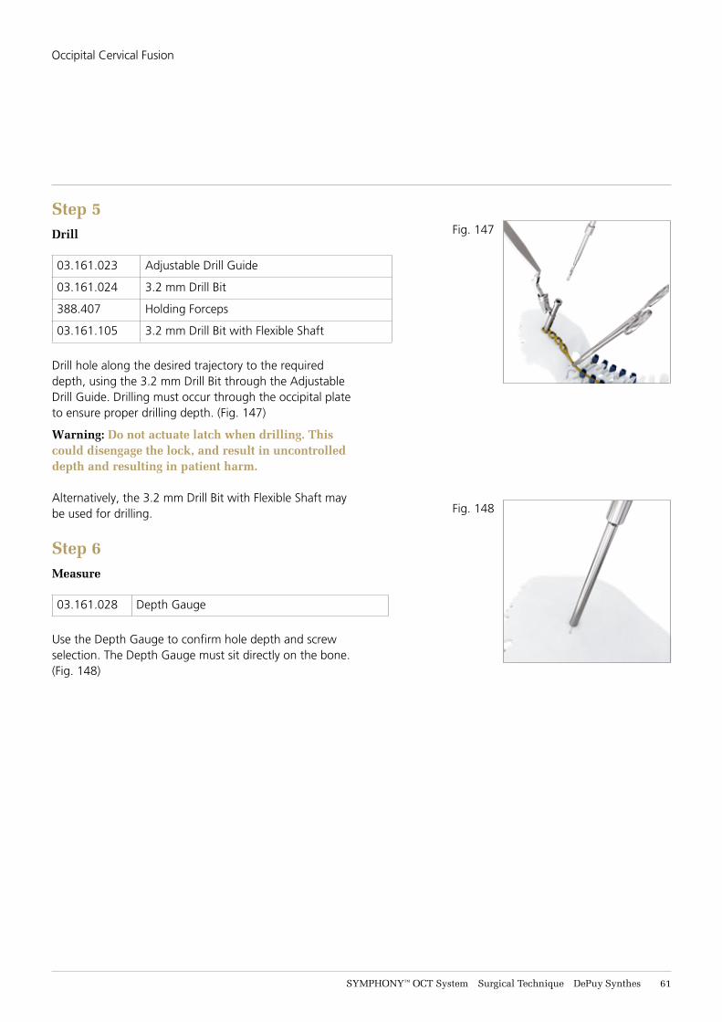
Step 5Drill
03.161.023 Adjustable Drill Guide
03.161.024 3.2 mm Drill Bit
388.407 Holding Forceps
03.161.105 3.2 mm Drill Bit with Flexible Shaft
Drill hole along the desired trajectory to the required depth, using the 3.2 mm Drill Bit through the Adjustable Drill Guide. Drilling must occur through the occipital plate to ensure proper drilling depth. (Fig. 147)
Warning: Do not actuate latch when drilling. This could disengage the lock, and result in uncontrolled depth and resulting in patient harm.
Alternatively, the 3.2 mm Drill Bit with Flexible Shaft may be used for drilling.
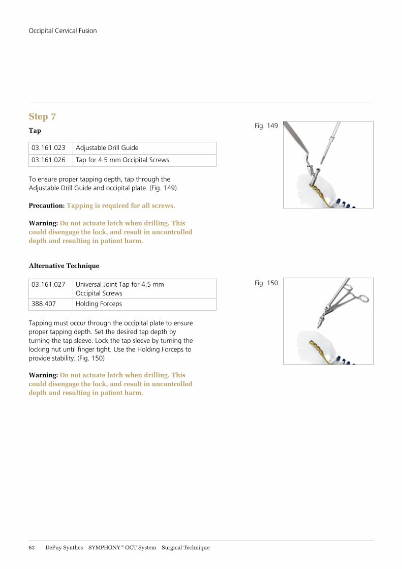
Step 6Measure
03.161.028 Depth Gauge
Use the Depth Gauge to confirm hole depth and screw selection. The Depth Gauge must sit directly on the bone. (Fig. 148)
Fig. 147
Fig. 148
Occipital Cervical Fusion
62 DePuy Synthes SYMPHONY™ OCT System Surgical Technique
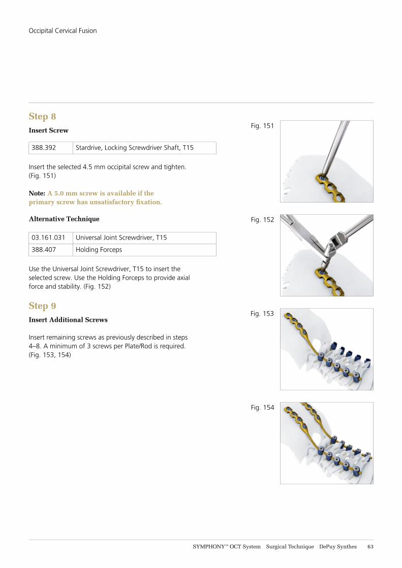
Step 7Tap
03.161.023 Adjustable Drill Guide
03.161.026 Tap for 4.5 mm Occipital Screws
To ensure proper tapping depth, tap through the Adjustable Drill Guide and occipital plate. (Fig. 149)
Precaution: Tapping is required for all screws.
Warning: Do not actuate latch when drilling. This could disengage the lock, and result in uncontrolled depth and resulting in patient harm.
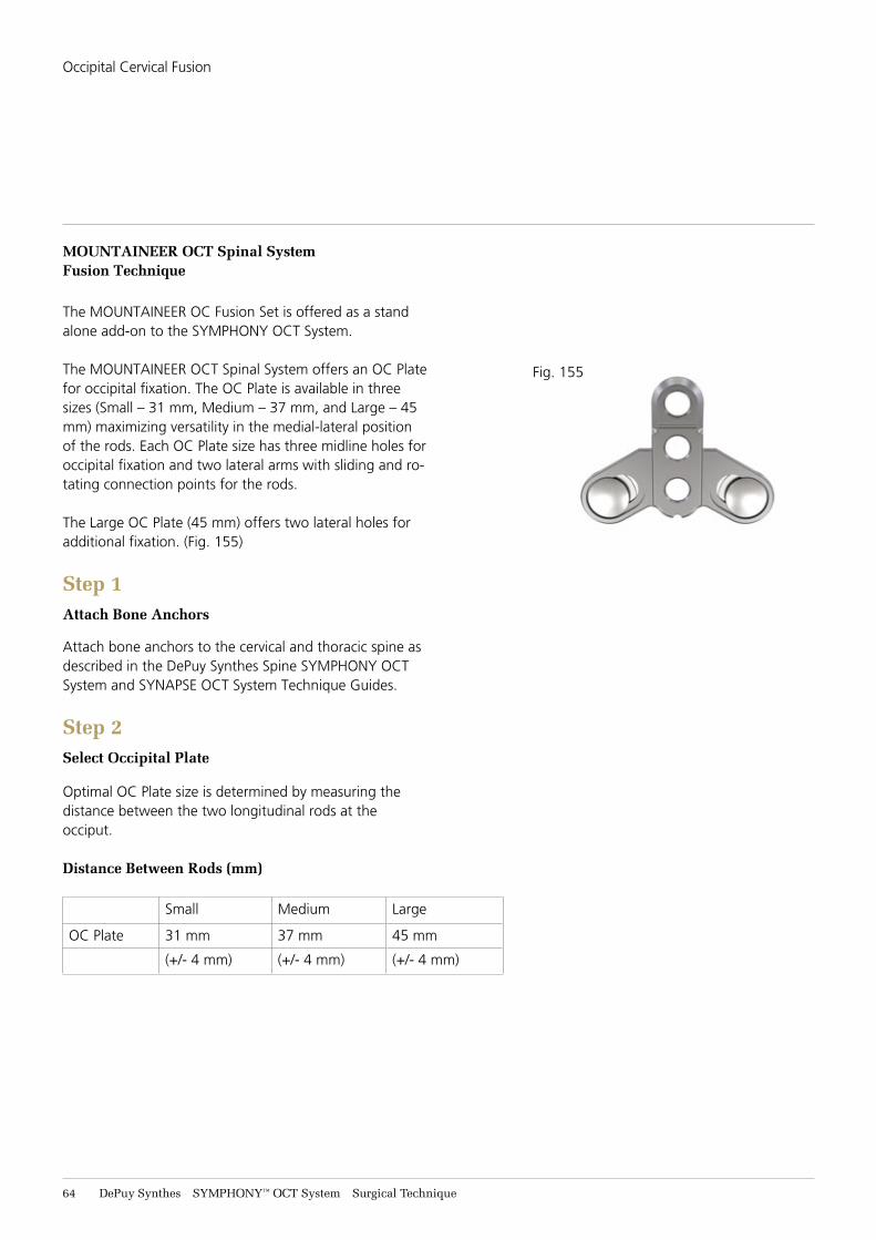
Alternative Technique
03.161.027 Universal Joint Tap for 4.5 mm Occipital Screws
388.407 Holding Forceps
Tapping must occur through the occipital plate to ensure proper tapping depth. Set the desired tap depth by turning the tap sleeve. Lock the tap sleeve by turning the locking nut until finger tight. Use the Holding Forceps to provide stability. (Fig. 150)
Warning: Do not actuate latch when drilling. This could disengage the lock, and result in uncontrolled depth and resulting in patient harm.
Fig. 149
Fig. 150
Occipital Cervical Fusion
SYMPHONY™ OCT System Surgical Technique DePuy Synthes 63
Step 8Insert Screw
388.392 Stardrive, Locking Screwdriver Shaft, T15
Insert the selected 4.5 mm occipital screw and tighten. (Fig. 151)
Note: A 5.0 mm screw is available if the primary screw has unsatisfactory fixation.
Alternative Technique
03.161.031 Universal Joint Screwdriver, T15
388.407 Holding Forceps
Use the Universal Joint Screwdriver, T15 to insert the selected screw. Use the Holding Forceps to provide axial force and stability. (Fig. 152)
Step 9Insert Additional Screws
Insert remaining screws as previously described in steps 4–8. A minimum of 3 screws per Plate/Rod is required. (Fig. 153, 154)
Fig. 151
Fig. 152
Fig. 153
Fig. 154
Occipital Cervical Fusion
64 DePuy Synthes SYMPHONY™ OCT System Surgical Technique
MOUNTAINEER OCT Spinal System Fusion Technique
The MOUNTAINEER OC Fusion Set is offered as a stand alone add-on to the SYMPHONY OCT System.
The MOUNTAINEER OCT Spinal System offers an OC Plate for occipital fixation. The OC Plate is available in three sizes (Small – 31 mm, Medium – 37 mm, and Large – 45 mm) maximizing versatility in the medial-lateral position of the rods. Each OC Plate size has three midline holes for occipital fixation and two lateral arms with sliding and ro-tating connection points for the rods.
The Large OC Plate (45 mm) offers two lateral holes for additional fixation. (Fig. 155)
Step 1Attach Bone Anchors
Attach bone anchors to the cervical and thoracic spine as described in the DePuy Synthes Spine SYMPHONY OCT System and SYNAPSE OCT System Technique Guides.
Step 2Select Occipital Plate
Optimal OC Plate size is determined by measuring the distance between the two longitudinal rods at the occiput.
Distance Between Rods (mm)
Small Medium Large
OC Plate 31 mm 37 mm 45 mm
(+/- 4 mm) (+/- 4 mm) (+/- 4 mm)
Fig. 155
Occipital Cervical Fusion
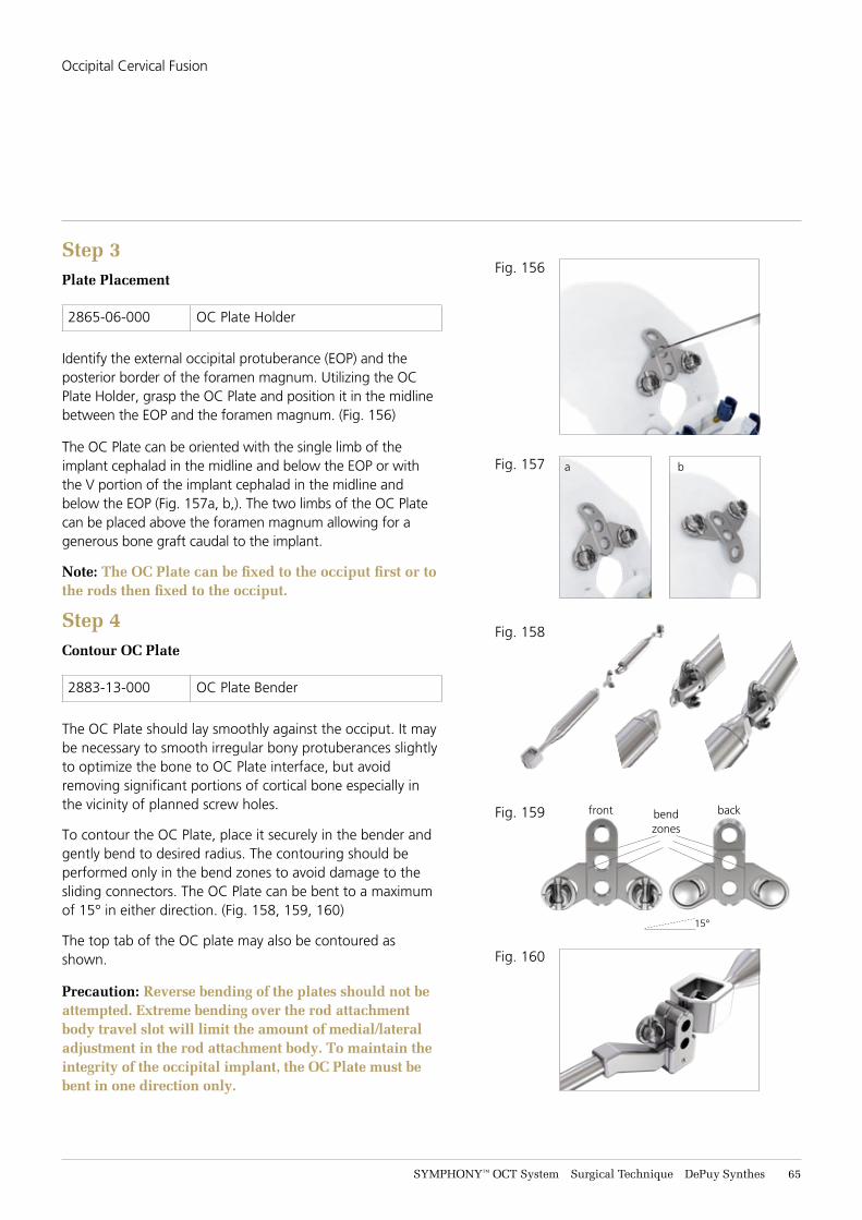
SYMPHONY™ OCT System Surgical Technique DePuy Synthes 65
Step 3Plate Placement
2865-06-000 OC Plate Holder
Identify the external occipital protuberance (EOP) and the posterior border of the foramen magnum. Utilizing the OC Plate Holder, grasp the OC Plate and position it in the midline between the EOP and the foramen magnum. (Fig. 156)
The OC Plate can be oriented with the single limb of the implant cephalad in the midline and below the EOP or with the V portion of the implant cephalad in the midline and below the EOP (Fig. 157a, b,). The two limbs of the OC Plate can be placed above the foramen magnum allowing for a generous bone graft caudal to the implant.
Note: The OC Plate can be fixed to the occiput first or to the rods then fixed to the occiput.
Step 4Contour OC Plate
2883-13-000 OC Plate Bender
The OC Plate should lay smoothly against the occiput. It may be necessary to smooth irregular bony protuberances slightly to optimize the bone to OC Plate interface, but avoid removing significant portions of cortical bone especially in the vicinity of planned screw holes.
To contour the OC Plate, place it securely in the bender and gently bend to desired radius. The contouring should be performed only in the bend zones to avoid damage to the sliding connectors. The OC Plate can be bent to a maximum of 15° in either direction. (Fig. 158, 159, 160)
The top tab of the OC plate may also be contoured as shown.
Precaution: Reverse bending of the plates should not be attempted. Extreme bending over the rod attachment body travel slot will limit the amount of medial/lateral adjustment in the rod attachment body. To maintain the integrity of the occipital implant, the OC Plate must be bent in one direction only.
Fig. 156
Fig. 157
Fig. 158
Fig. 160
Fig. 159 bendzones
front back
15°
a b
Occipital Cervical Fusion
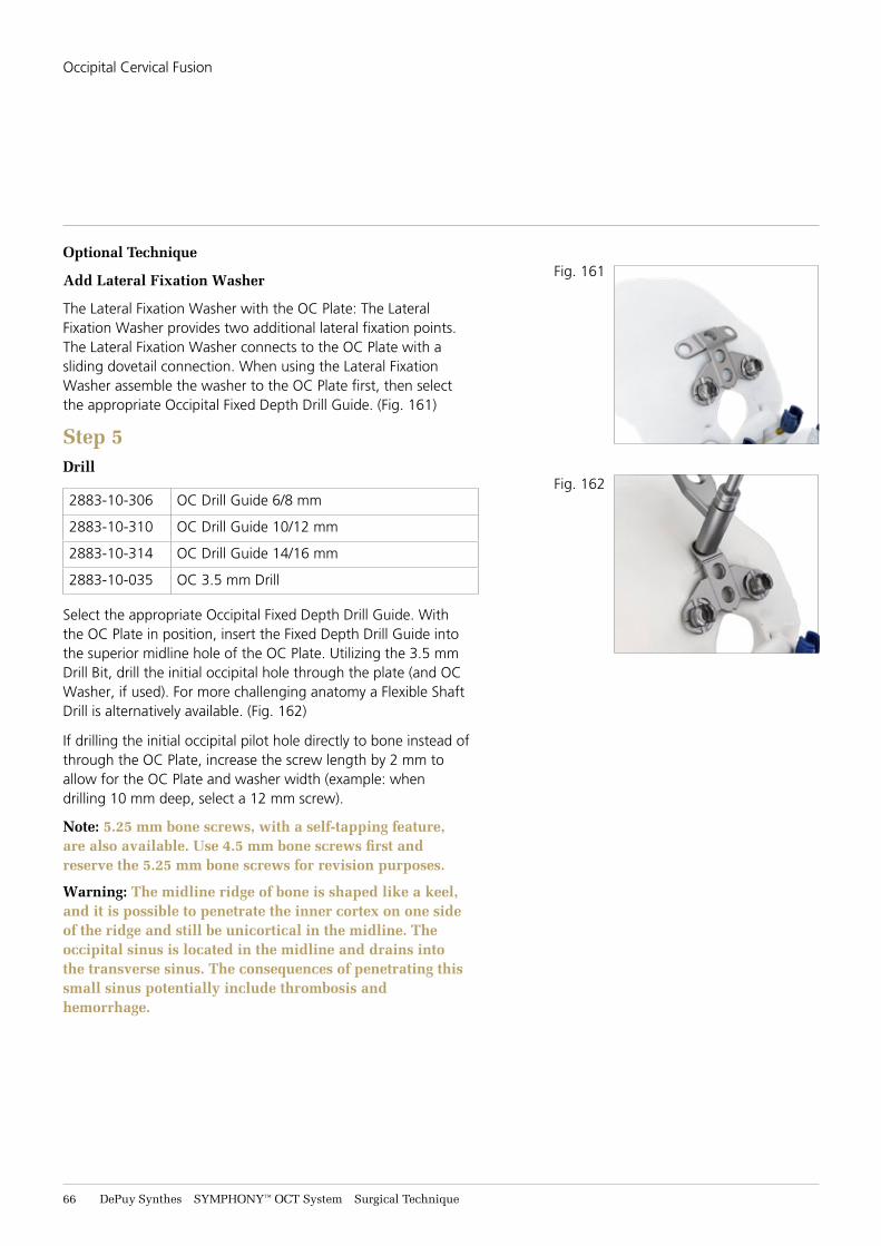
66 DePuy Synthes SYMPHONY™ OCT System Surgical Technique
Optional Technique
Add Lateral Fixation Washer
The Lateral Fixation Washer with the OC Plate: The Lateral Fixation Washer provides two additional lateral fixation points. The Lateral Fixation Washer connects to the OC Plate with a sliding dovetail connection. When using the Lateral Fixation Washer assemble the washer to the OC Plate first, then select the appropriate Occipital Fixed Depth Drill Guide. (Fig. 161)
Step 5Drill
2883-10-306 OC Drill Guide 6/8 mm
2883-10-310 OC Drill Guide 10/12 mm
2883-10-314 OC Drill Guide 14/16 mm
2883-10-035 OC 3.5 mm Drill
Select the appropriate Occipital Fixed Depth Drill Guide. With the OC Plate in position, insert the Fixed Depth Drill Guide into the superior midline hole of the OC Plate. Utilizing the 3.5 mm Drill Bit, drill the initial occipital hole through the plate (and OC Washer, if used). For more challenging anatomy a Flexible Shaft Drill is alternatively available. (Fig. 162)
If drilling the initial occipital pilot hole directly to bone instead of through the OC Plate, increase the screw length by 2 mm to allow for the OC Plate and washer width (example: when drilling 10 mm deep, select a 12 mm screw).
Note: 5.25 mm bone screws, with a self-tapping feature, are also available. Use 4.5 mm bone screws first and reserve the 5.25 mm bone screws for revision purposes.
Warning: The midline ridge of bone is shaped like a keel, and it is possible to penetrate the inner cortex on one side of the ridge and still be unicortical in the midline. The occipital sinus is located in the midline and drains into the transverse sinus. The consequences of penetrating this small sinus potentially include thrombosis and hemorrhage.
Fig. 161
Fig. 162
Occipital Cervical Fusion
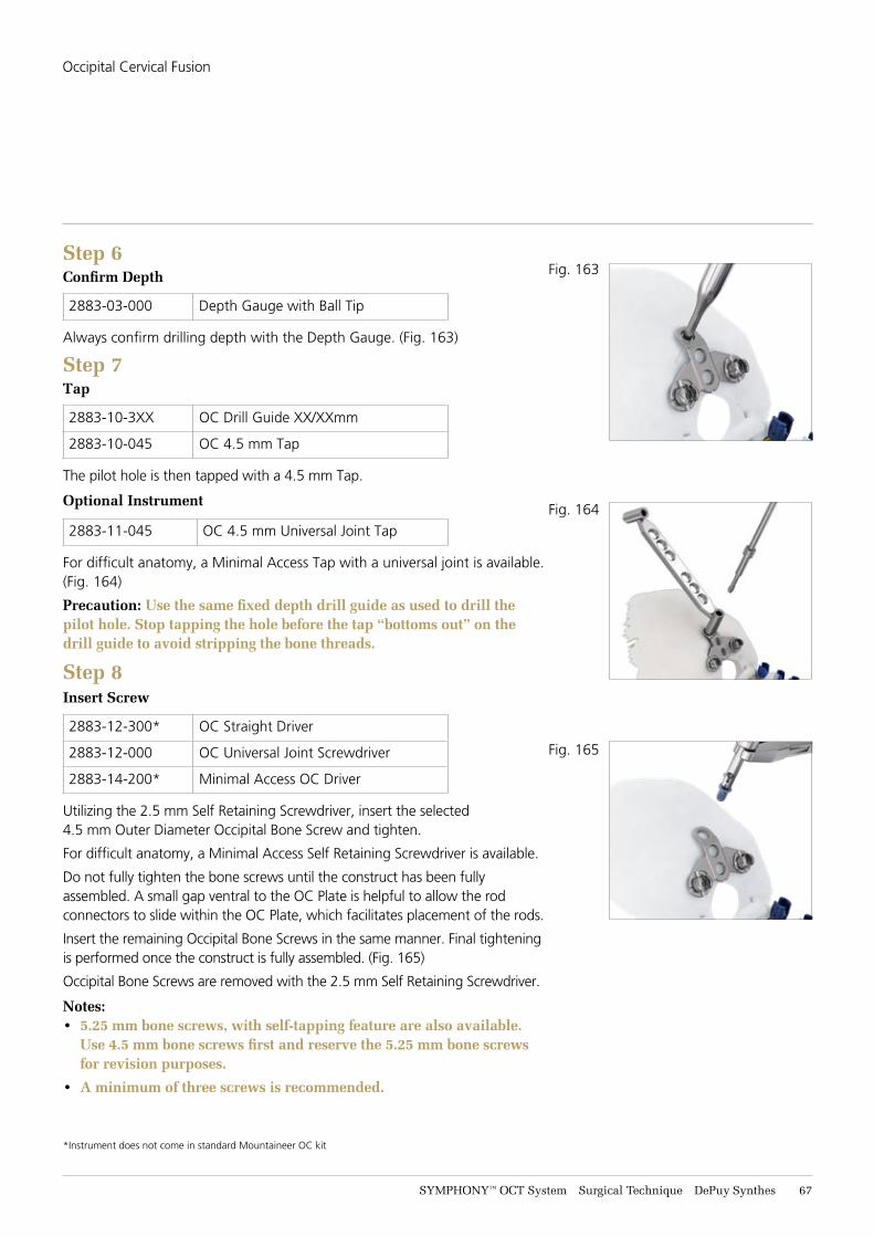
SYMPHONY™ OCT System Surgical Technique DePuy Synthes 67
Step 6Confirm Depth
2883-03-000 Depth Gauge with Ball Tip
Always confirm drilling depth with the Depth Gauge. (Fig. 163)
Step 7Tap
2883-10-3XX OC Drill Guide XX/XXmm
2883-10-045 OC 4.5 mm Tap
The pilot hole is then tapped with a 4.5 mm Tap.
Optional Instrument
2883-11-045 OC 4.5 mm Universal Joint Tap
For difficult anatomy, a Minimal Access Tap with a universal joint is available. (Fig. 164)
Precaution: Use the same fixed depth drill guide as used to drill the pilot hole. Stop tapping the hole before the tap “bottoms out” on the drill guide to avoid stripping the bone threads.
Step 8Insert Screw
2883-12-300* OC Straight Driver
2883-12-000 OC Universal Joint Screwdriver
2883-14-200* Minimal Access OC Driver
Utilizing the 2.5 mm Self Retaining Screwdriver, insert the selected 4.5 mm Outer Diameter Occipital Bone Screw and tighten.
For difficult anatomy, a Minimal Access Self Retaining Screwdriver is available.
Do not fully tighten the bone screws until the construct has been fully assembled. A small gap ventral to the OC Plate is helpful to allow the rod connectors to slide within the OC Plate, which facilitates placement of the rods.
Insert the remaining Occipital Bone Screws in the same manner. Final tightening is performed once the construct is fully assembled. (Fig. 165)
Occipital Bone Screws are removed with the 2.5 mm Self Retaining Screwdriver.
Notes: • 5.25 mm bone screws, with self-tapping feature are also available.
Use 4.5 mm bone screws first and reserve the 5.25 mm bone screws for revision purposes.
• A minimum of three screws is recommended.
*Instrument does not come in standard Mountaineer OC kit
Fig. 164
Fig. 165
Fig. 163
Occipital Cervical Fusion
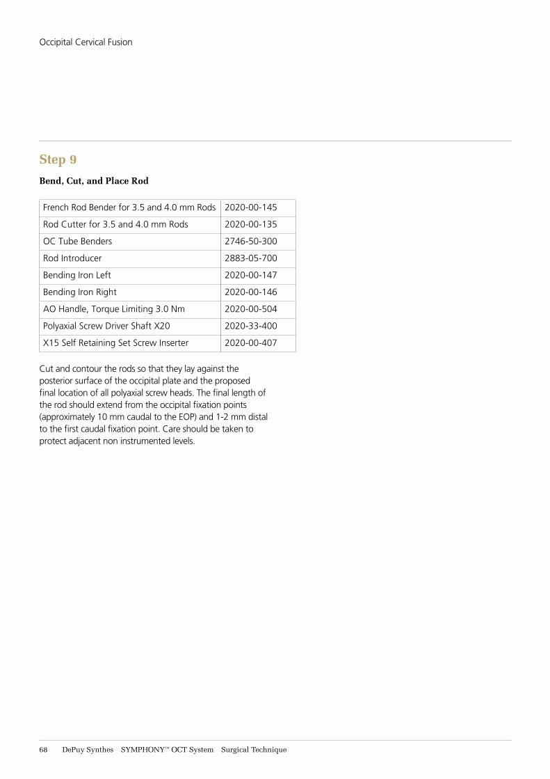
68 DePuy Synthes SYMPHONY™ OCT System Surgical Technique
Step 9
Bend, Cut, and Place Rod
French Rod Bender for 3.5 and 4.0 mm Rods 2020-00-145
Rod Cutter for 3.5 and 4.0 mm Rods 2020-00-135
OC Tube Benders 2746-50-300
Rod Introducer 2883-05-700
Bending Iron Left 2020-00-147
Bending Iron Right 2020-00-146
AO Handle, Torque Limiting 3.0 Nm 2020-00-504
Polyaxial Screw Driver Shaft X20 2020-33-400
X15 Self Retaining Set Screw Inserter 2020-00-407
Cut and contour the rods so that they lay against the posterior surface of the occipital plate and the proposed final location of all polyaxial screw heads. The final length of the rod should extend from the occipital fixation points (approximately 10 mm caudal to the EOP) and 1-2 mm distal to the first caudal fixation point. Care should be taken to protect adjacent non instrumented levels.
Occipital Cervical Fusion
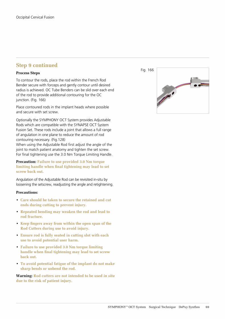
SYMPHONY™ OCT System Surgical Technique DePuy Synthes 69
Step 9 continuedProcess Steps
To contour the rods, place the rod within the French Rod Bender secure with forceps and gently contour until desired radius is achieved. OC Tube Benders can be slid over each end of the rod to provide additional contouring for the OC junction. (Fig. 166)
Place contoured rods in the implant heads where possible and secure with set screw.
Optionally the SYMPHONY OCT System provides Adjustable Rods which are compatible with the SYNAPSE OCT System Fusion Set. These rods include a joint that allows a full range of angulation in one plane to reduce the amount of rod contouring necessary. (Fig.128)When using the Adjustable Rod first adjust the angle of the joint to match patient anatomy and tighten the set screw. For final tightening use the 3.0 Nm Torque Limiting Handle.
Precaution: Failure to use provided 3.0 Nm torque limiting handle when final tightening may lead to set screw back out.
Angulation of the Adjustable Rod can be revisited in-situ by loosening the setscrew, readjusting the angle and retightening.
Precautions:
• Care should be taken to secure the retained and cut ends during cutting to prevent injury.
• Repeated bending may weaken the rod and lead to rod fracture.
• Keep fingers away from within the open span of the Rod Cutters during use to avoid injury.
• Ensure rod is fully seated in cutting slot with each use to avoid potential user harm.
• Failure to use provided 3.0 Nm torque limiting handle when final tightening may lead to set screw back out.
• To avoid potential fatigue of the implant do not make sharp bends or unbend the rod.
Warning: Rod cutters are not intended to be used in situ due to the risk of patient injury.
Fig. 166
Occipital Cervical Fusion
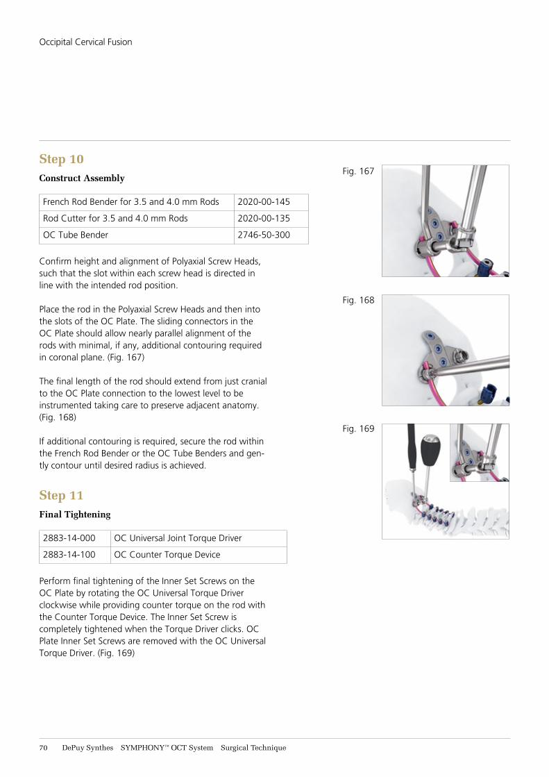
71 DePuy Synthes SYMPHONY™ OCT System Surgical Technique
Step 10Construct Assembly
French Rod Bender for 3.5 and 4.0 mm Rods 2020-00-145
Rod Cutter for 3.5 and 4.0 mm Rods 2020-00-135
OC Tube Bender 2746-50-300
Confirm height and alignment of Polyaxial Screw Heads, such that the slot within each screw head is directed in line with the intended rod position.
Place the rod in the Polyaxial Screw Heads and then into the slots of the OC Plate. The sliding connectors in the OC Plate should allow nearly parallel alignment of the rods with minimal, if any, additional contouring required in coronal plane. (Fig. 167)
The final length of the rod should extend from just cranial to the OC Plate connection to the lowest level to be instrumented taking care to preserve adjacent anatomy. (Fig. 168)
If additional contouring is required, secure the rod within the French Rod Bender or the OC Tube Benders and gen-tly contour until desired radius is achieved.
Step 11Final Tightening
2883-14-000 OC Universal Joint Torque Driver
2883-14-100 OC Counter Torque Device
Perform final tightening of the Inner Set Screws on the OC Plate by rotating the OC Universal Torque Driver clockwise while providing counter torque on the rod with the Counter Torque Device. The Inner Set Screw is completely tightened when the Torque Driver clicks. OC Plate Inner Set Screws are removed with the OC Universal Torque Driver. (Fig. 169)
Fig. 167
Fig. 168
Fig. 169
Occipital Cervical Fusion
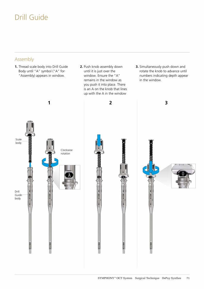
SYMPHONY™ OCT System Surgical Technique DePuy Synthes 71
Drill Guide
Assembly1. Thread scale body into Drill Guide
Body until “A” symbol (“A” for “Assembly) appears in window.
2. Push knob assembly down until it is just over the window. Ensure the “A” remains in the window as you push it into place. There is an A on the knob that lines up with the A in the window
3. Simultaneously push down and rotate the knob to advance until numbers indicating depth appear in the window.
1 2 3
Clockwise rotation
Scale body
DrillGuidebody
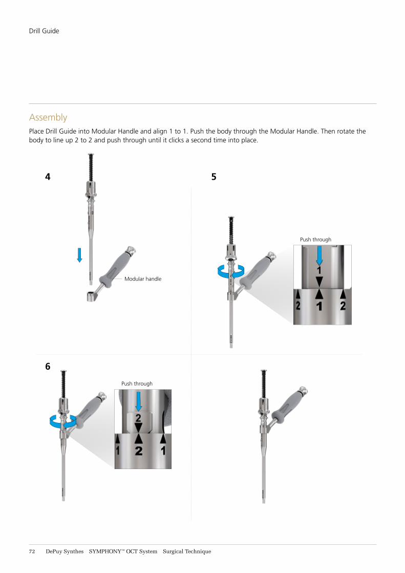
72 DePuy Synthes SYMPHONY™ OCT System Surgical Technique
Drill Guide
Assembly
6
Push through
Push through
Modular handle
4 5
Place Drill Guide into Modular Handle and align 1 to 1. Push the body through the Modular Handle. Then rotate the body to line up 2 to 2 and push through until it clicks a second time into place.
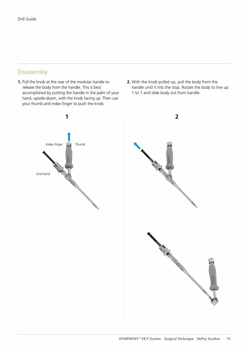
SYMPHONY™ OCT System Surgical Technique DePuy Synthes 73
Disassembly
1 2
ThumbIndex finger
2nd hand
Drill Guide
1. Pull the knob at the rear of the modular handle to release the body from the handle. This is best accomplished by putting the handle in the palm of your hand, upside-down, with the knob facing up. Then use your thumb and index finger to push the knob.
2. With the knob pulled up, pull the body from the handle until it hits the stop. Rotate the body to line up 1 to 1 and slide body out from handle.
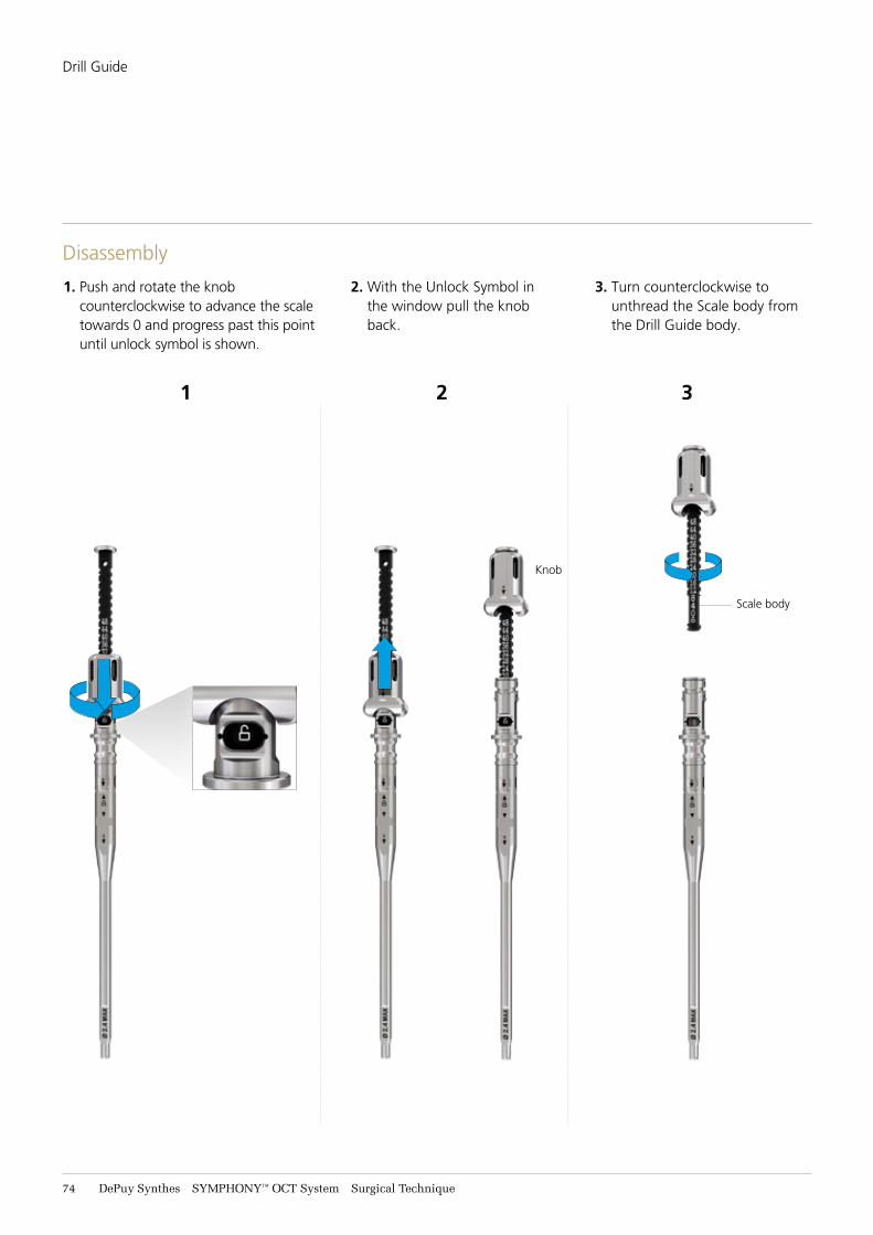
74 DePuy Synthes SYMPHONY™ OCT System Surgical Technique
Disassembly
1. Push and rotate the knob counterclockwise to advance the scale towards 0 and progress past this point until unlock symbol is shown.
2. With the Unlock Symbol in the window pull the knob back.
3. Turn counterclockwise to unthread the Scale body from the Drill Guide body.
3
Knob
Scale body
1 2
Drill Guide
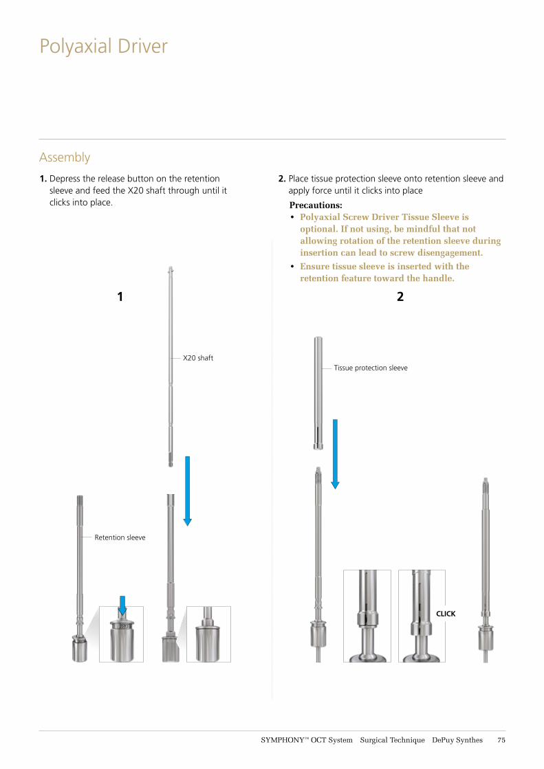
SYMPHONY™ OCT System Surgical Technique DePuy Synthes 75
Polyaxial Driver
Assembly
1. Depress the release button on the retention sleeve and feed the X20 shaft through until it clicks into place.
2. Place tissue protection sleeve onto retention sleeve and apply force until it clicks into place
Precautions: • Polyaxial Screw Driver Tissue Sleeve is
optional. If not using, be mindful that not allowing rotation of the retention sleeve during insertion can lead to screw disengagement.
• Ensure tissue sleeve is inserted with the retention feature toward the handle.
CLICK
Retention sleeve
X20 shaftTissue protection sleeve
1 2
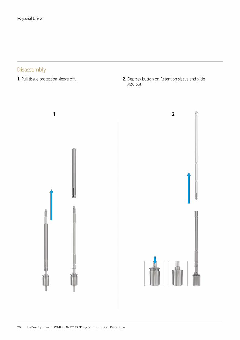
76 DePuy Synthes SYMPHONY™ OCT System Surgical Technique
Polyaxial Driver
Disassembly
1. Pull tissue protection sleeve off. 2. Depress button on Retention sleeve and slide X20 out.
1 2
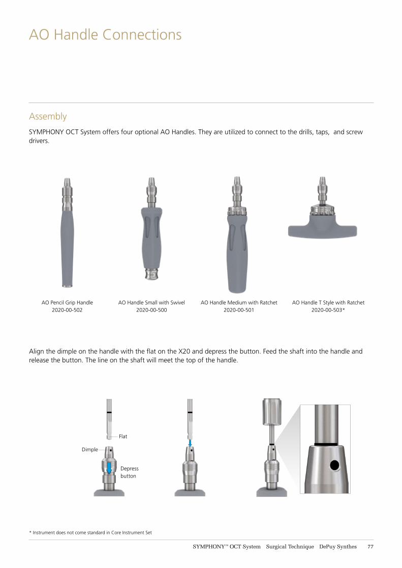
SYMPHONY™ OCT System Surgical Technique DePuy Synthes 77
AO Handle Connections
AO Handle Small with Swivel 2020-00-500
AO Pencil Grip Handle 2020-00-502
AO Handle Medium with Ratchet 2020-00-501
AO Handle T Style with Ratchet 2020-00-503*
Dimple
Flat
Depressbutton
Align the dimple on the handle with the flat on the X20 and depress the button. Feed the shaft into the handle and release the button. The line on the shaft will meet the top of the handle.
SYMPHONY OCT System offers four optional AO Handles. They are utilized to connect to the drills, taps, and screw drivers.
Assembly
* Instrument does not come standard in Core Instrument Set
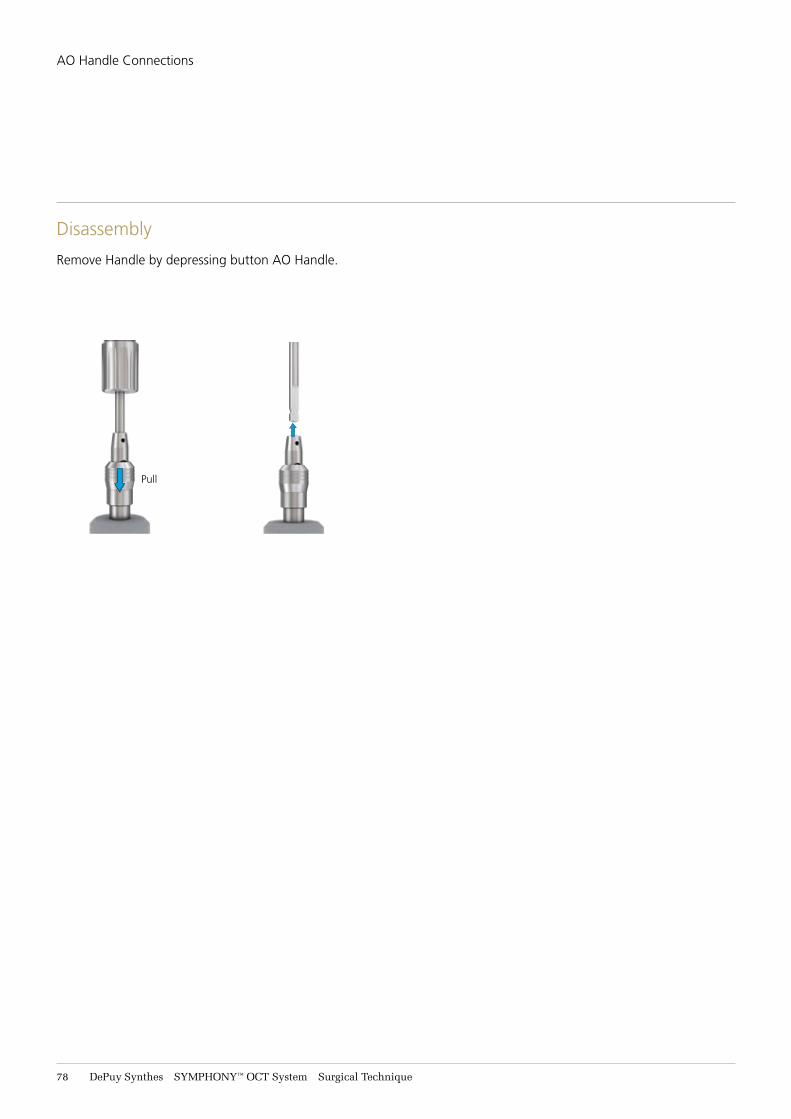
78 DePuy Synthes SYMPHONY™ OCT System Surgical Technique
AO Handle Connections
Disassembly
Pull
Remove Handle by depressing button AO Handle.
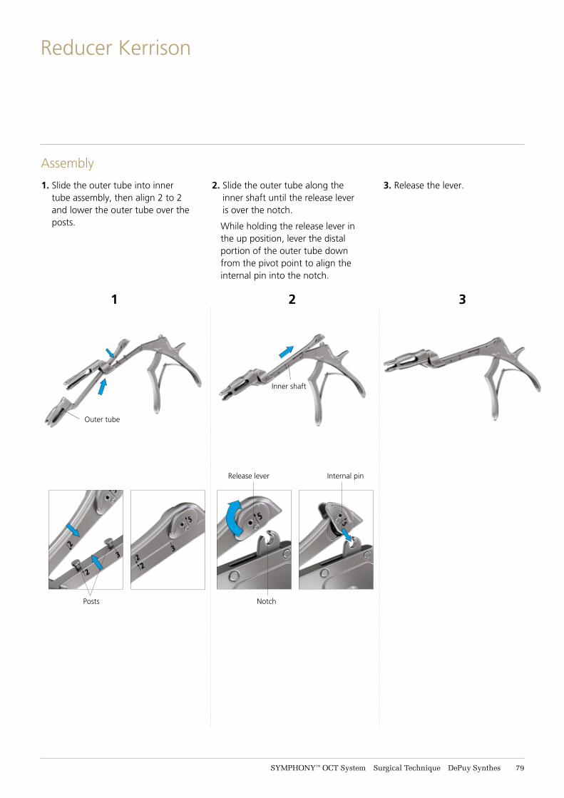
SYMPHONY™ OCT System Surgical Technique DePuy Synthes 79
Reducer Kerrison
Assembly
1. Slide the outer tube into inner tube assembly, then align 2 to 2 and lower the outer tube over the posts.
2. Slide the outer tube along the inner shaft until the release lever is over the notch.
While holding the release lever in the up position, lever the distal portion of the outer tube down from the pivot point to align the internal pin into the notch.
3. Release the lever.
Outer tube
Inner shaft
Release lever
Notch
Internal pin
1 2 3
Posts
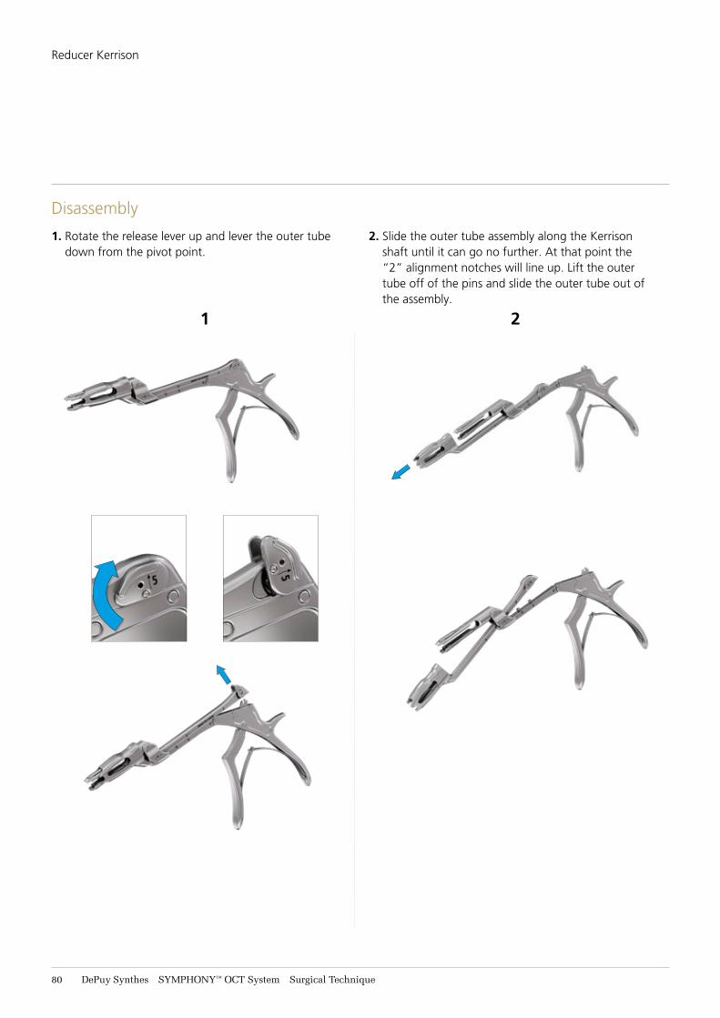
81 DePuy Synthes SYMPHONY™ OCT System Surgical Technique
Reducer Kerrison
Disassembly
1 2
1. Rotate the release lever up and lever the outer tube down from the pivot point.
2. Slide the outer tube assembly along the Kerrison shaft until it can go no further. At that point the “2” alignment notches will line up. Lift the outer tube off of the pins and slide the outer tube out of the assembly.
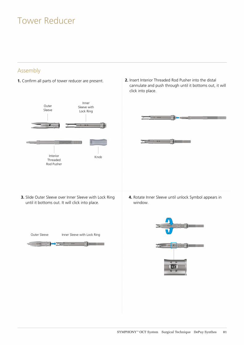
SYMPHONY™ OCT System Surgical Technique DePuy Synthes 81
Tower Reducer
Assembly
1. Confirm all parts of tower reducer are present. 2. Insert Interior Threaded Rod Pusher into the distal cannulate and push through until it bottoms out, it will click into place.
3. Slide Outer Sleeve over Inner Sleeve with Lock Ring until it bottoms out. It will click into place.
4. Rotate Inner Sleeve until unlock Symbol appears in window.
Outer Sleeve Inner Sleeve with Lock Ring
Knob
Outer Sleeve
Inner Sleeve with Lock Ring
Interior Threaded
Rod Pusher
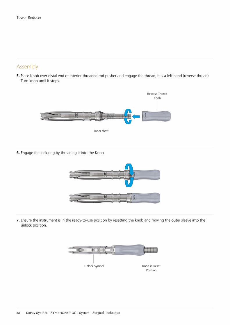
82 DePuy Synthes SYMPHONY™ OCT System Surgical Technique
Tower Reducer
Assembly
5. Place Knob over distal end of interior threaded rod pusher and engage the thread, it is a left hand (reverse thread). Turn knob until it stops.
6. Engage the lock ring by threading it into the Knob.
7. Ensure the instrument is in the ready-to-use position by resetting the knob and moving the outer sleeve into the unlock position.
Inner shaft
Reverse Thread Knob
Knob in Reset Position
Unlock Symbol
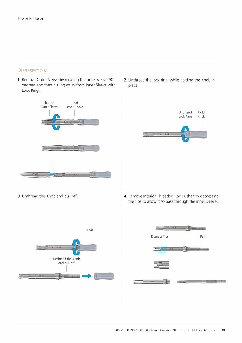
SYMPHONY™ OCT System Surgical Technique DePuy Synthes 83
Disassembly
HoldInner Sleeve
RotateOuter Sleeve
UnthreadLock Ring
HoldKnob
Knob
Unthread the Knob and pull off
Depress Tips Pull
1. Remove Outer Sleeve by rotating the outer sleeve 90 degrees and then pulling away from Inner Sleeve with Lock Ring.
2. Unthread the lock ring, while holding the Knob in place.
3. Unthread the Knob and pull off. 4. Remove Interior Threaded Rod Pusher by depressing the tips to allow it to pass through the inner sleeve.
Tower Reducer
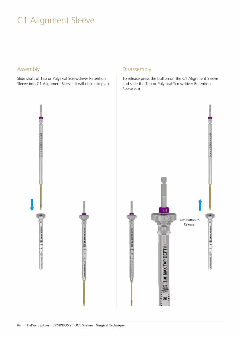
84 DePuy Synthes SYMPHONY™ OCT System Surgical Technique
C1 Alignment Sleeve
Assembly Disassembly
Slide shaft of Tap or Polyaxial Screwdriver Retention Sleeve into C1 Alignment Sleeve. It will click into place.
To release press the button on the C1 Alignment Sleeve and slide the Tap or Polyaxial Screwdriver Retention Sleeve out.
Press Button to Release
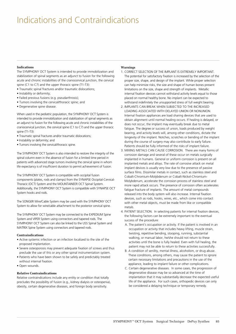
SYMPHONY™ OCT System Surgical Technique DePuy Synthes 85
Indications and Contraindications
IndicationsThe SYMPHONY OCT System is intended to provide immobilization and stabilization of spinal segments as an adjunct to fusion for the following acute and chronic instabilities of the craniocervical junction, the cervical spine (C1 to C7) and the upper thoracic spine (T1-T3): • Traumatic spinal fractures and/or traumatic dislocations;• Instability or deformity;• Failed previous fusions (e.g. pseudarthrosis);• Tumors involving the cervical/thoracic spine; and• Degenerative spine disease.
When used in the pediatric population, the SYMPHONY OCT System is intended to provide immobilization and stabilization of spinal segments as an adjunct to fusion for the following acute and chronic instabilities of the craniocervical junction, the cervical spine (C1 to C7) and the upper thoracic spine (T1-T3): • Traumatic spinal fractures and/or traumatic dislocations;• Instability or deformity; and• Tumors involving the cervical/thoracic spine.
The SYMPHONY OCT System is also intended to restore the integrity of the spinal column even in the absence of fusion for a limited time period in patients with advanced stage tumors involving the cervical spine in whom life expectancy is of insufficient duration to permit achievement of fusion.
The SYMPHONY OCT System is compatible with occipital fusion components (plates, rods and clamps) from the SYNAPSE Occipital-Cervical-Thoracic (OCT) System and the MOUNTAINEER OCT Spinal System. Additionally, the SYMPHONY OCT System is compatible with SYNAPSE OCT System hooks and rods.
The SONGER Wire/Cable System may be used with the SYMPHONY OCT System to allow for wire/cable attachment to the posterior cervical spine.
The SYMPHONY OCT System may be connected to the EXPEDIUM Spine System and VIPER System using connectors and tapered rods. The SYMPHONY OCT System can also be linked to the USS Spinal System and MATRIX Spine System using connectors and tapered rods.
Contraindications• Active systemic infection or an infection localized to the site of the
proposed implantation.• Severe osteoporosis may prevent adequate fixation of screws and thus
preclude the use of this or any other spinal instrumentation system.• Patients who have been shown to be safely and predictably treated
without internal fixation.• Open wounds.
Relative ContraindicationsRelative contraindications include any entity or condition that totally precludes the possibility of fusion (e.g., kidney dialysis or osteopenia), obesity, certain degenerative diseases, and foreign body sensitivity.
Warnings1. CORRECT SELECTION OF THE IMPLANT IS EXTREMELY IMPORTANT.
The potential for satisfactory fixation is increased by the selection of the proper size, shape, and design of the implant. While proper selection can help minimize risks, the size and shape of human bones present limitations on the size, shape and strength of implants. Metallic internal fixation devices cannot withstand activity levels equal to those placed on normal healthy bone. No implant can be expected to withstand indefinitely the unsupported stress of full weight bearing.
2. IMPLANTS CAN BREAK WHEN SUBJECTED TO THE INCREASED LOADING ASSOCIATED WITH DELAYED UNION OR NONUNION. Internal fixation appliances are load sharing devices that are used to obtain alignment until normal healing occurs. If healing is delayed, or does not occur, the implant may eventually break due to metal fatigue. The degree or success of union, loads produced by weight bearing, and activity levels will, among other conditions, dictate the longevity of the implant. Notches, scratches or bending of the implant during the course of surgery may also contribute to early failure. Patients should be fully informed of the risks of implant failure.
3. MIXING METALS CAN CAUSE CORROSION. There are many forms of corrosion damage and several of these occur on metals surgically implanted in humans. General or uniform corrosion is present on all implanted metals and alloys. The rate of corrosive attack on metal implant devices is usually very low due to the presence of passive surface films. Dissimilar metals in contact, such as stainless steel and Cobalt-Chromium-Molybdenum or Cobalt-Nickel-Chromium-Molybdenum, accelerate the corrosion process of stainless steel and more rapid attack occurs. The presence of corrosion often accelerates fatigue fracture of implants. The amount of metal compounds released into the body system will also increase. Internal fixation devices, such as rods, hooks, wires, etc., which come into contact with other metal objects, must be made from like or compatible metals.
4. PATIENT SELECTION. In selecting patients for internal fixation devices, the following factors can be extremely important to the eventual success of the procedure:
A. The patient’s occupation or activity. If the patient is involved in an occupation or activity that includes heavy lifting, muscle strain, twisting, repetitive bending, stooping, running, substantial walking, or manual labor, he/she should not return to these activities until the bone is fully healed. Even with full healing, the patient may not be able to return to these activities successfully.
B. A condition of senility, mental illness, alcoholism, or drug abuse. These conditions, among others, may cause the patient to ignore certain necessary limitations and precautions in the use of the appliance, leading to implant failure or other complications.
C. Certain degenerative diseases. In some cases, the progression of degenerative disease may be so advanced at the time of implantation that it may substantially decrease the expected useful life of the appliance. For such cases, orthopedic devices can only be considered a delaying technique or temporary remedy.
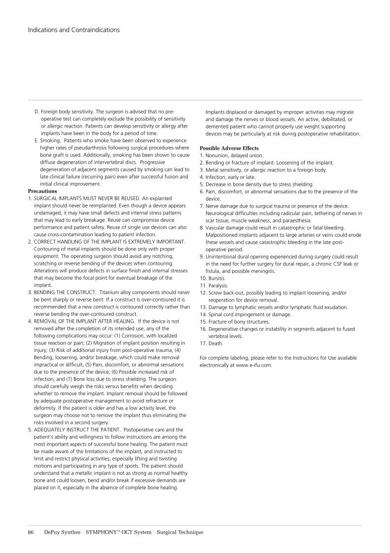
86 DePuy Synthes SYMPHONY™ OCT System Surgical Technique
Indications and Contraindications
D. Foreign body sensitivity. The surgeon is advised that no pre-operative test can completely exclude the possibility of sensitivity or allergic reaction. Patients can develop sensitivity or allergy after implants have been in the body for a period of time.
E. Smoking. Patients who smoke have been observed to experience higher rates of pseudarthrosis following surgical procedures where bone graft is used. Additionally, smoking has been shown to cause diffuse degeneration of intervertebral discs. Progressive degeneration of adjacent segments caused by smoking can lead to late clinical failure (recurring pain) even after successful fusion and initial clinical improvement.
Precautions1. SURGICAL IMPLANTS MUST NEVER BE REUSED. An explanted
implant should never be reimplanted. Even though a device appears undamaged, it may have small defects and internal stress patterns that may lead to early breakage. Reuse can compromise device performance and patient safety. Reuse of single use devices can also cause cross-contamination leading to patient infection.
2. CORRECT HANDLING OF THE IMPLANT IS EXTREMELY IMPORTANT. Contouring of metal implants should be done only with proper equipment. The operating surgeon should avoid any notching, scratching or reverse bending of the devices when contouring. Alterations will produce defects in surface finish and internal stresses that may become the focal point for eventual breakage of the implant.
3. BENDING THE CONSTRUCT. Titanium alloy components should never be bent sharply or reverse bent. If a construct is over-contoured it is recommended that a new construct is contoured correctly rather than reverse bending the over-contoured construct.
4. REMOVAL OF THE IMPLANT AFTER HEALING. If the device is not removed after the completion of its intended use, any of the following complications may occur: (1) Corrosion, with localized tissue reaction or pain; (2) Migration of implant position resulting in injury; (3) Risk of additional injury from post-operative trauma; (4) Bending, loosening, and/or breakage, which could make removal impractical or difficult; (5) Pain, discomfort, or abnormal sensations due to the presence of the device; (6) Possible increased risk of infection; and (7) Bone loss due to stress shielding. The surgeon should carefully weigh the risks versus benefits when deciding whether to remove the implant. Implant removal should be followed by adequate postoperative management to avoid refracture or deformity. If the patient is older and has a low activity level, the surgeon may choose not to remove the implant thus eliminating the risks involved in a second surgery.
5. ADEQUATELY INSTRUCT THE PATIENT. Postoperative care and the patient’s ability and willingness to follow instructions are among the most important aspects of successful bone healing. The patient must be made aware of the limitations of the implant, and instructed to limit and restrict physical activities, especially lifting and twisting motions and participating in any type of sports. The patient should understand that a metallic implant is not as strong as normal healthy bone and could loosen, bend and/or break if excessive demands are placed on it, especially in the absence of complete bone healing.
Implants displaced or damaged by improper activities may migrate and damage the nerves or blood vessels. An active, debilitated, or demented patient who cannot properly use weight supporting devices may be particularly at risk during postoperative rehabilitation.
Possible Adverse Effects1. Nonunion, delayed union.2. Bending or fracture of implant. Loosening of the implant.3. Metal sensitivity, or allergic reaction to a foreign body.4. Infection, early or late.5. Decrease in bone density due to stress shielding.6. Pain, discomfort, or abnormal sensations due to the presence of the
device.7. Nerve damage due to surgical trauma or presence of the device.
Neurological difficulties including radicular pain, tethering of nerves in scar tissue, muscle weakness, and paraesthesia.
8. Vascular damage could result in catastrophic or fatal bleeding. Malpositioned implants adjacent to large arteries or veins could erode these vessels and cause catastrophic bleeding in the late post-operative period.
9. Unintentional dural opening experienced during surgery could result in the need for further surgery for dural repair, a chronic CSF leak or fistula, and possible meningitis.
10. Bursitis.11. Paralysis.12. Screw back-out, possibly leading to implant loosening, and/or
reoperation for device removal.13. Damage to lymphatic vessels and/or lymphatic fluid exudation.14. Spinal cord impingement or damage.15. Fracture of bony structures.16. Degenerative changes or instability in segments adjacent to fused
vertebral levels.17. Death.
For complete labeling, please refer to the Instructions for Use available electronically at www.e-ifu.com.

Limited Warranty and Disclaimer: DePuy Synthes products are sold with a limited warranty to the original purchaser against defects in workmanship and materials. Any other express or implied warranties, including warranties of merchantability or fitness, are hereby disclaimed. Please also refer to the package insert(s) or other labeling associated with the devices identified in this surgical technique for additional information.
Not all products are currently available in all markets.
This publication is not intended for distribution outside of the EMEA region.
The third-party trademarks used herein are the trademarks of their respective owners.
All surgical techniques are available as PDF files at www.depuysynthes.com/ifu
For full product details and precautions, please consult the Instructions For Use.
Note: For recognized manufacturer, refer to product label.
DePuy Spine Inc.325 Paramount Drive Raynham, MA 02767 USA
Medos International SÀRLChemin Blanc 382400 Le LocleSwitzerland
Manufactured or dostributed by:
www.jnjmedicaldevices.com
© DePuy Synthes Spine, a division of Synthes GmbH. 2021. All rights reserved.113993-210506 EMEA