Embed Size (px)
Citation preview
0711S20000CV
Grand Rapids, Michigan, U.S.A. 49504-5298
USER’S OPERATING AND INSTRUCTION MANUAL
MODEL 711
COUNTER TOP SLICER
MODEL 711 COUNTER TOP SLICER
Rev. 3/1/04 0711S20000
INDEX
SAFETY INSTRUCTIONS.......................................................................... GEN861015
SLICER INSTALLATION............................................................................ 0711S20002
SLICER SPECIFICATIONS....................................................................... 0711S20003
OPERATION INSTRUCTIONS.................................................................. 0711S20004
MAINTENANCE......................................................................................... 0711S20005
Removing Blade Frames .................................................................. 0711S20005-1 Replacing Blade Frames................................................................... 0711S20005-4 Changing The Blades........................................................................0711S20005-4 Tightening The Belt........................................................................... 0711S20005-6 Replacing The Belt............................................................................ 0711S20005-7 Replacing The Gas Spring................................................................ 0711S20005-7 Lubrication...................................................................................... 0711S20005-10 Cleaning.......................................................................................... 0711S20005-10
ADJUSTMENTS......................................................................................... 0711S20006
Slices Vary In Thickness................................................................... 0711S20006-1 Adjusting The Gas Spring................................................................. 0711S20006-1 Clearance Between Blade Frames....................................................0711S20006-2
TROUBLE SHOOTING GUIDE.................................................................. 0711S20007
RECOMMENDED SPARE PARTS LIST.................................................... 0711S20012
EXPLODED ASSEMBLY DRAWING......................................................... 0711S20013
MECHANICAL PARTS LIST...................................................................... 0711S20008
60/50 CY ELECTRICAL PARTS LIST (Standard Machines)...................... 0711S20009
Exploded Drawing 60/50 Cy.............................................................. 0711S20009-1 Wiring Diagram 1-60/50-115/110 & 1-60/50-230/220........................0711S20009-1 Electrical Parts List 1/60/115............................................................. 0711S20009-2 Electrical Parts List 1/60/230............................................................. 0711S20009-3
Electrical Parts List 1/50/110............................................................. 0711S20009-4 Electrical Parts List 1/50/220............................................................. 0711S20009-5
“SELF SERVE” OPTION............................................................................ 0711S20011
Parts List & Exploded Drawing.......................................................... 0711S20011-1 Wiring Diagram 1-60/50-115/110 & 1-60/50-230/220........................0711S20011-2
WARRANTY............................................................................................... GEN040225
WARRANTY PROCEDURE....................................................................... GEN040226
RETURNED PARTS POLICY ……............................................................. GEN040227

GEN020319
THIS PAGE WAS INTENTIONALLY
LEFT BLANK.
General Document
SAFETY INSTRUCTIONS
Various safety devices and methods of guarding have been provided on this machine. It is essential, however, that machine operators and maintenance personnel observe the following safety precautions. Improper installation or operation of this equipment may cause injury to personnel or damage to equipment.
1. Read this manual before attempting to operate your machine. Never allow an untrained person to operate or service this machine.
2. Connect the machine to a properly grounded electrical supply that matches the requirements shown on the electrical specification plate and follow specifications of local electrical codes.
3. Disconnect and lock-out the machine from the power supply before cleaning or servicing.
4. Check and secure all guards before starting the machine.
5. Observe all caution and warning labels affixed to the machine.
6. Use only proper replacement parts.
7. Do not wear loose fitting clothing or loose hair. Shirt tails should be tucked in.
8. Wear proper personal safety equipment.
9. Keep Hands away form the moving parts of this machine while it is in operation.
10. In addition to these general safety instructions, also follow the more specific safety instructions given for the different areas of the machine in the operating instructions.
WARNING
DO NOT USE FOR OTHER THAN ORIGINALLY INTENDED PURPOSE
REV. 12-15-95 GEN861015

GEN020319
THIS PAGE WAS INTENTIONALLY
LEFT BLANK.
MODEL 711 COUNTER TOP SLICER
REV. 11-30-00 0711S20002
SLICER INSTALLATION
WARNING
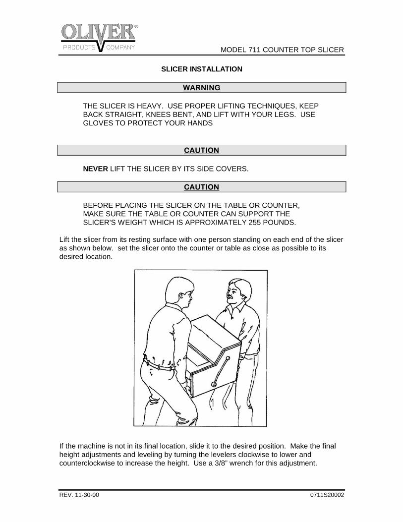
THE SLICER IS HEAVY. USE PROPER LIFTING TECHNIQUES, KEEP BACK STRAIGHT, KNEES BENT, AND LIFT WITH YOUR LEGS. USE GLOVES TO PROTECT YOUR HANDS
CAUTION
NEVER LIFT THE SLICER BY ITS SIDE COVERS.
CAUTION BEFORE PLACING THE SLICER ON THE TABLE OR COUNTER, MAKE SURE THE TABLE OR COUNTER CAN SUPPORT THE SLICER’S WEIGHT WHICH IS APPROXIMATELY 255 POUNDS. Lift the slicer from its resting surface with one person standing on each end of the slicer as shown below. set the slicer onto the counter or table as close as possible to its desired location.
If the machine is not in its final location, slide it to the desired position. Make the final height adjustments and leveling by turning the levelers clockwise to lower and counterclockwise to increase the height. Use a 3/8” wrench for this adjustment.
MODEL 711 COUNTER TOP SLICER
REV. 6-4-03 0711S20003
SLICER SPECIFICATIONS
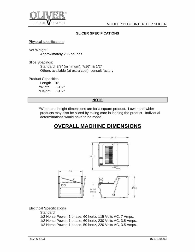
Physical specifications Net Weight: Approximately 255 pounds. Slice Spacings: Standard 3/8” (minimum), 7/16”, & 1/2” Others available (at extra cost), consult factory Product Capacities: Length 16” * Width 5-1/2” * Height 5-1/2”
NOTE * Width and height dimensions are for a square product. Lower and wider products may also be sliced by taking care in loading the product. Individual determinations would have to be made.
OVERALL MACHINE DIMENSIONS
Electrical Specifications Standard 1/2 Horse Power, 1 phase, 60 hertz, 115 Volts AC, 7 Amps. 1/2 Horse Power, 1 phase, 60 hertz, 230 Volts AC, 3.5 Amps. 1/2 Horse Power, 1 phase, 50 hertz, 220 Volts AC, 3.5 Amps.
MODEL 711 COUNTER TOP SLICER
0711S20004-1
OPERATING INSTRUCTIONS
WARNING
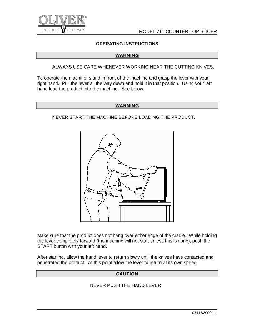
ALWAYS USE CARE WHENEVER WORKING NEAR THE CUTTING KNIVES. To operate the machine, stand in front of the machine and grasp the lever with your right hand. Pull the lever all the way down and hold it in that position. Using your left hand load the product into the machine. See below.
WARNING NEVER START THE MACHINE BEFORE LOADING THE PRODUCT.
Make sure that the product does not hang over either edge of the cradle. While holding the lever completely forward (the machine will not start unless this is done), push the START button with your left hand. After starting, allow the hand lever to return slowly until the knives have contacted and penetrated the product. At this point allow the lever to return at its own speed.
CAUTION NEVER PUSH THE HAND LEVER.
MODEL 711 COUNTER TOP SLICER
0711S20004-2
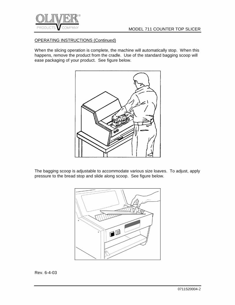
OPERATING INSTRUCTIONS (Continued) When the slicing operation is complete, the machine will automatically stop. When this happens, remove the product from the cradle. Use of the standard bagging scoop will ease packaging of your product. See figure below.
The bagging scoop is adjustable to accommodate various size loaves. To adjust, apply pressure to the bread stop and slide along scoop. See figure below.
Rev. 6-4-03
MODEL 711 COUNTER TOP SLICER
0711S20005-1
MAINTENANCE
WARNING
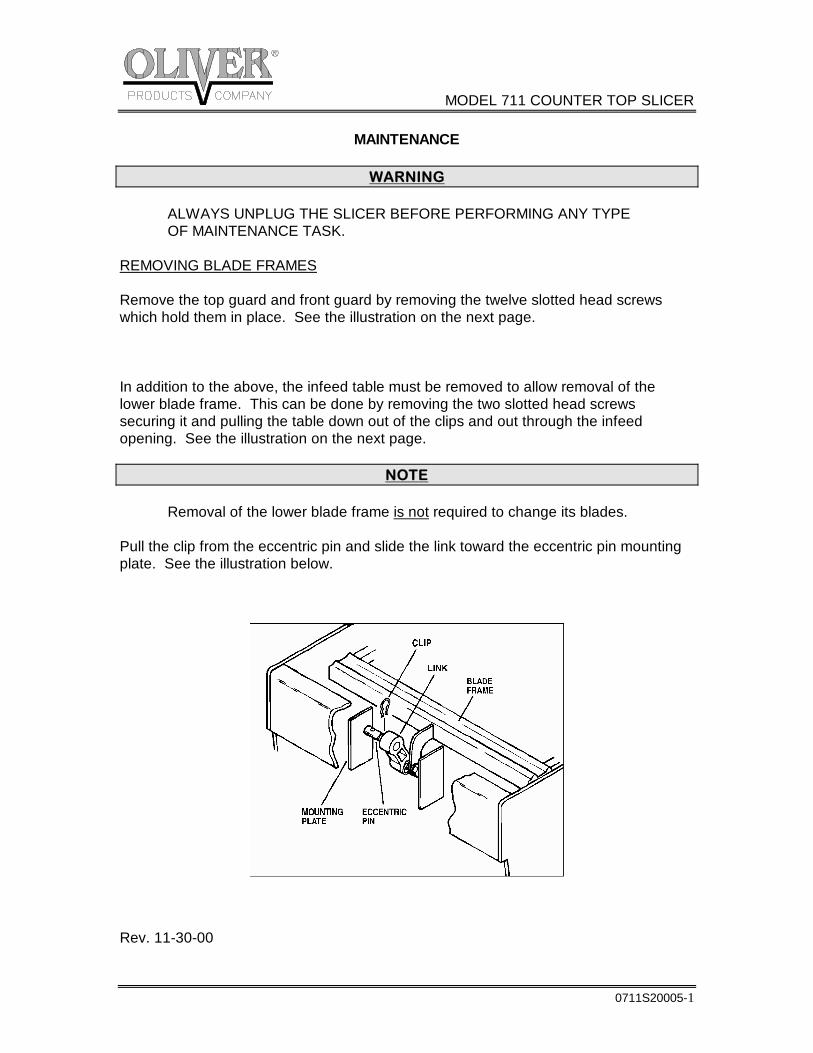
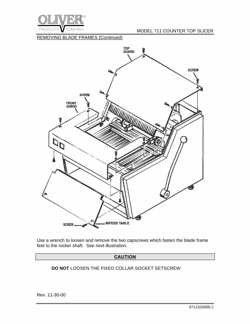
ALWAYS UNPLUG THE SLICER BEFORE PERFORMING ANY TYPE OF MAINTENANCE TASK. REMOVING BLADE FRAMES Remove the top guard and front guard by removing the twelve slotted head screws which hold them in place. See the illustration on the next page. In addition to the above, the infeed table must be removed to allow removal of the lower blade frame. This can be done by removing the two slotted head screws securing it and pulling the table down out of the clips and out through the infeed opening. See the illustration on the next page.
NOTE Removal of the lower blade frame is not required to change its blades. Pull the clip from the eccentric pin and slide the link toward the eccentric pin mounting plate. See the illustration below.
Rev. 11-30-00
MODEL 711 COUNTER TOP SLICER
0711S20005-2
REMOVING BLADE FRAMES (Continued)
Use a wrench to loosen and remove the two capscrews which fasten the blade frame feet to the rocker shaft. See next illustration.
CAUTION DO NOT LOOSEN THE FIXED COLLAR SOCKET SETSCREW Rev. 11-30-00
MODEL 711 COUNTER TOP SLICER
0711S20005-3
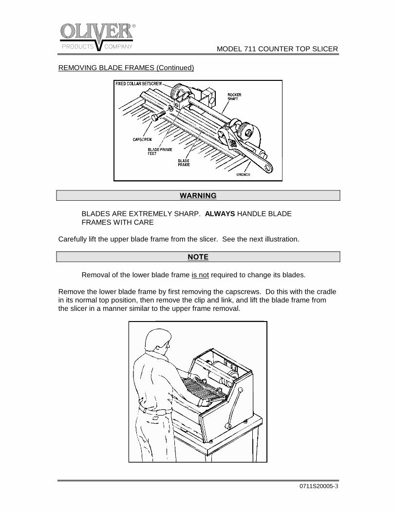
REMOVING BLADE FRAMES (Continued)
WARNING BLADES ARE EXTREMELY SHARP. ALWAYS HANDLE BLADE FRAMES WITH CARE Carefully lift the upper blade frame from the slicer. See the next illustration.
NOTE Removal of the lower blade frame is not required to change its blades. Remove the lower blade frame by first removing the capscrews. Do this with the cradle in its normal top position, then remove the clip and link, and lift the blade frame from the slicer in a manner similar to the upper frame removal.
MODEL 711 COUNTER TOP SLICER
0711S20005-4
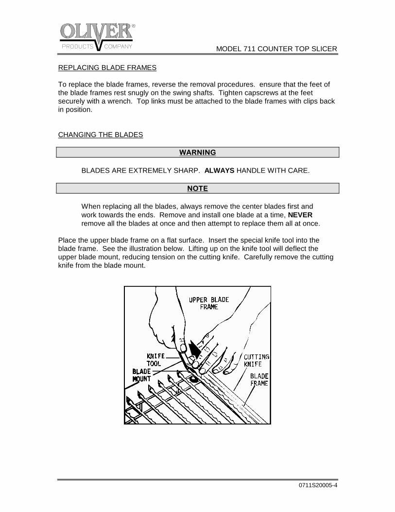
REPLACING BLADE FRAMES To replace the blade frames, reverse the removal procedures. ensure that the feet of the blade frames rest snugly on the swing shafts. Tighten capscrews at the feet securely with a wrench. Top links must be attached to the blade frames with clips back in position. CHANGING THE BLADES
WARNING BLADES ARE EXTREMELY SHARP. ALWAYS HANDLE WITH CARE.
NOTE When replacing all the blades, always remove the center blades first and work towards the ends. Remove and install one blade at a time, NEVER remove all the blades at once and then attempt to replace them all at once. Place the upper blade frame on a flat surface. Insert the special knife tool into the blade frame. See the illustration below. Lifting up on the knife tool will deflect the upper blade mount, reducing tension on the cutting knife. Carefully remove the cutting knife from the blade mount.
MODEL 711 COUNTER TOP SLICER
0711S20005-5
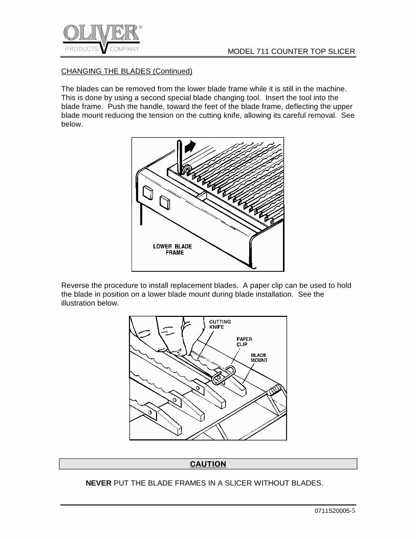
CHANGING THE BLADES (Continued) The blades can be removed from the lower blade frame while it is still in the machine. This is done by using a second special blade changing tool. Insert the tool into the blade frame. Push the handle, toward the feet of the blade frame, deflecting the upper blade mount reducing the tension on the cutting knife, allowing its careful removal. See below.
Reverse the procedure to install replacement blades. A paper clip can be used to hold the blade in position on a lower blade mount during blade installation. See the illustration below.
CAUTION NEVER PUT THE BLADE FRAMES IN A SLICER WITHOUT BLADES.
MODEL 711 COUNTER TOP SLICER
0711S20005-6
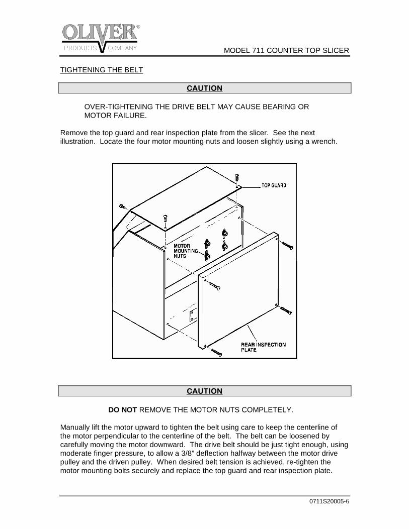
TIGHTENING THE BELT
CAUTION OVER-TIGHTENING THE DRIVE BELT MAY CAUSE BEARING OR MOTOR FAILURE. Remove the top guard and rear inspection plate from the slicer. See the next illustration. Locate the four motor mounting nuts and loosen slightly using a wrench.
CAUTION DO NOT REMOVE THE MOTOR NUTS COMPLETELY. Manually lift the motor upward to tighten the belt using care to keep the centerline of the motor perpendicular to the centerline of the belt. The belt can be loosened by carefully moving the motor downward. The drive belt should be just tight enough, using moderate finger pressure, to allow a 3/8” deflection halfway between the motor drive pulley and the driven pulley. When desired belt tension is achieved, re-tighten the motor mounting bolts securely and replace the top guard and rear inspection plate.
MODEL 711 COUNTER TOP SLICER
0711S20005-7
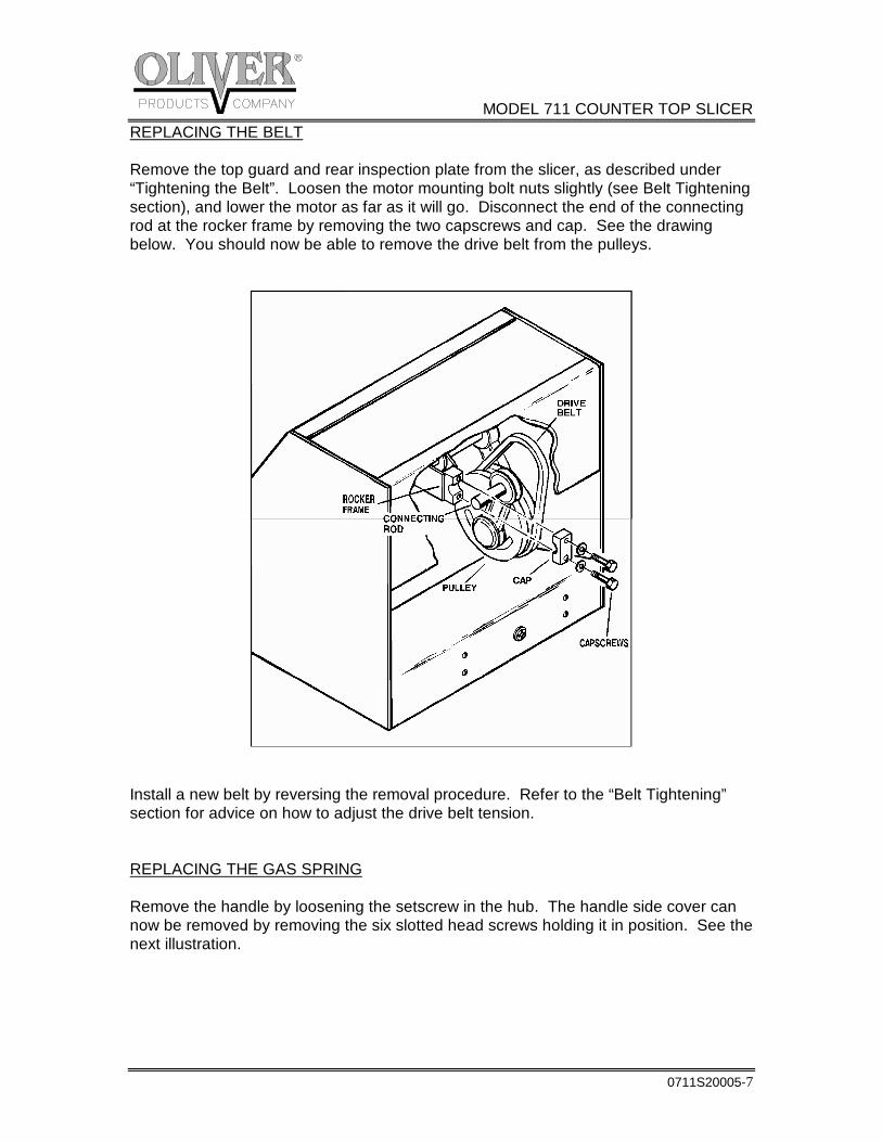
REPLACING THE BELT Remove the top guard and rear inspection plate from the slicer, as described under “Tightening the Belt”. Loosen the motor mounting bolt nuts slightly (see Belt Tightening section), and lower the motor as far as it will go. Disconnect the end of the connecting rod at the rocker frame by removing the two capscrews and cap. See the drawing below. You should now be able to remove the drive belt from the pulleys.
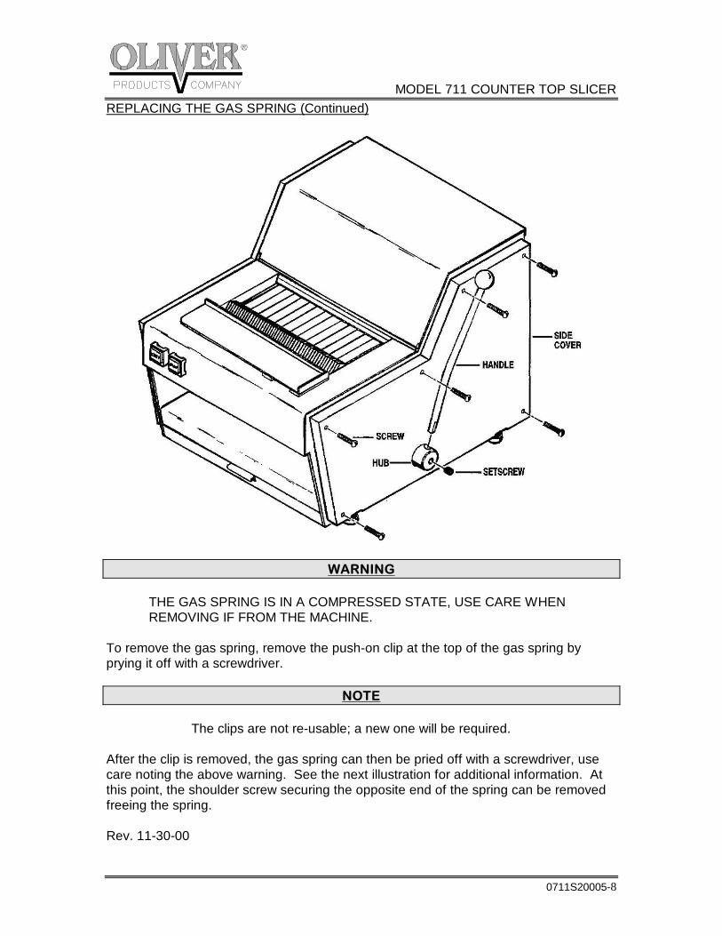
Install a new belt by reversing the removal procedure. Refer to the “Belt Tightening” section for advice on how to adjust the drive belt tension. REPLACING THE GAS SPRING Remove the handle by loosening the setscrew in the hub. The handle side cover can now be removed by removing the six slotted head screws holding it in position. See the next illustration.
MODEL 711 COUNTER TOP SLICER
0711S20005-8
REPLACING THE GAS SPRING (Continued)
WARNING THE GAS SPRING IS IN A COMPRESSED STATE, USE CARE WHEN REMOVING IF FROM THE MACHINE. To remove the gas spring, remove the push-on clip at the top of the gas spring by prying it off with a screwdriver.
NOTE The clips are not re-usable; a new one will be required. After the clip is removed, the gas spring can then be pried off with a screwdriver, use care noting the above warning. See the next illustration for additional information. At this point, the shoulder screw securing the opposite end of the spring can be removed freeing the spring. Rev. 11-30-00
MODEL 711 COUNTER TOP SLICER
0711S20005-9
REPLACING THE GAS SPRING (Continued)
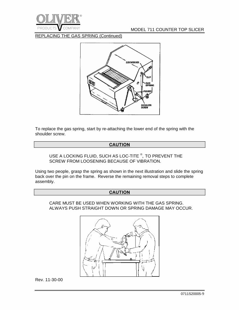
To replace the gas spring, start by re-attaching the lower end of the spring with the shoulder screw.
CAUTION USE A LOCKING FLUID, SUCH AS LOC-TITE , TO PREVENT THE SCREW FROM LOOSENING BECAUSE OF VIBRATION. Using two people, grasp the spring as shown in the next illustration and slide the spring back over the pin on the frame. Reverse the remaining removal steps to complete assembly.
CAUTION CARE MUST BE USED WHEN WORKING WITH THE GAS SPRING. ALWAYS PUSH STRAIGHT DOWN OR SPRING DAMAGE MAY OCCUR.
Rev. 11-30-00
MODEL 711 COUNTER TOP SLICER
0711S20005-10
LUBRICATION Once a month put a drop of a food approved lubricant on the plastic links at the top of the blade frames. Also add a drop or two to each bushing on the pusher drive cross shaft and lever shaft. All other bearings are greased packed or sealed and seldom need attention.
NOTE Never oil or grease the motor. CLEANING Use a mild detergent solution to clean the exterior surfaces and empty the crumb tray daily or as necessary. Periodically remove all guards and covers and brush or blow, if compressed air is available, all foreign material from all surfaces, especially moving parts.
MODEL 711 COUNTER TOP SLICER
0711S20006-1
ADJUSTMENTS
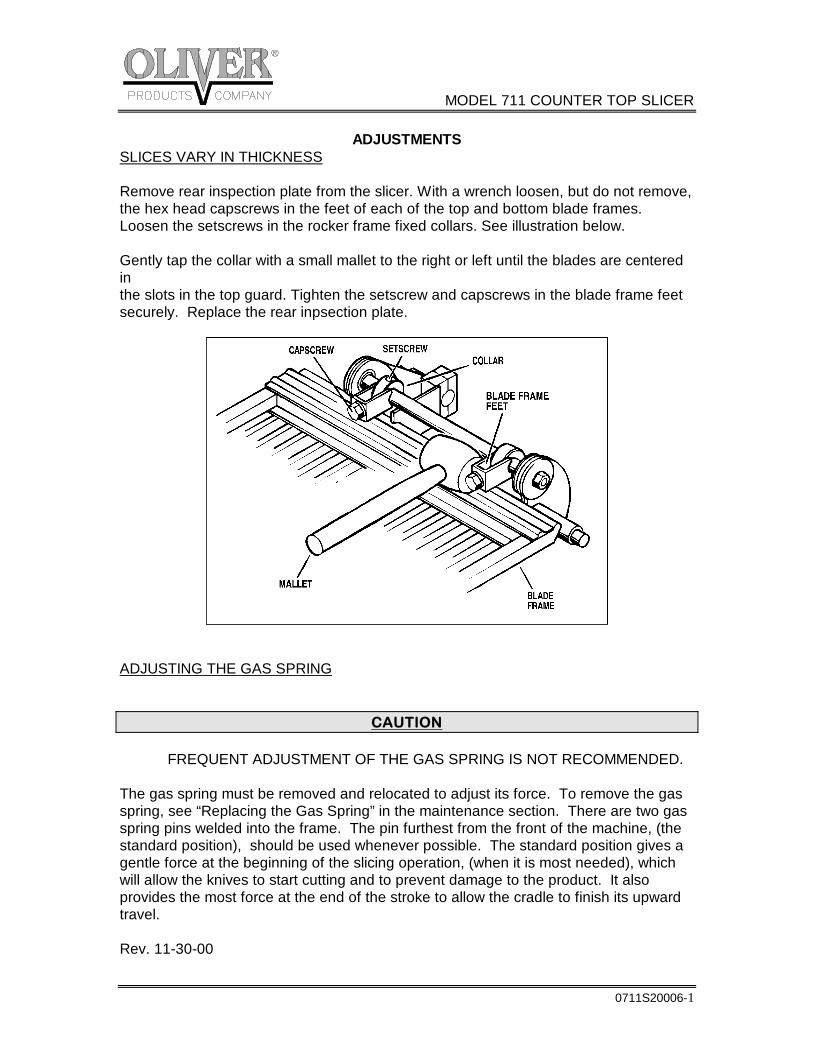
SLICES VARY IN THICKNESS Remove rear inspection plate from the slicer. With a wrench loosen, but do not remove, the hex head capscrews in the feet of each of the top and bottom blade frames. Loosen the setscrews in the rocker frame fixed collars. See illustration below. Gently tap the collar with a small mallet to the right or left until the blades are centered in the slots in the top guard. Tighten the setscrew and capscrews in the blade frame feet securely. Replace the rear inpsection plate.
ADJUSTING THE GAS SPRING
CAUTION FREQUENT ADJUSTMENT OF THE GAS SPRING IS NOT RECOMMENDED. The gas spring must be removed and relocated to adjust its force. To remove the gas spring, see “Replacing the Gas Spring” in the maintenance section. There are two gas spring pins welded into the frame. The pin furthest from the front of the machine, (the standard position), should be used whenever possible. The standard position gives a gentle force at the beginning of the slicing operation, (when it is most needed), which will allow the knives to start cutting and to prevent damage to the product. It also provides the most force at the end of the stroke to allow the cradle to finish its upward travel. Rev. 11-30-00
MODEL 711 COUNTER TOP SLICER
0711S20006-2
ADJUSTING THE GAS SPRING (Continued) The pin located in the high forward position should be used when greater force is desired as the product is first entering the knives. Using proper gas spring installation procedures, see “Replacing a Gas Spring”, in the maintenance section, compress the spring and mount it on the desired pin, secure it with a new clip.
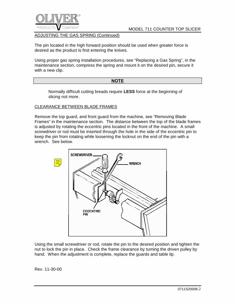
NOTE Normally difficult cutting breads require LESS force at the beginning of slicing not more. CLEARANCE BETWEEN BLADE FRAMES Remove the top guard, and front guard from the machine, see “Removing Blade Frames” in the maintenance section. The distance between the top of the blade frames is adjusted by rotating the eccentric pins located in the front of the machine. A small screwdriver or rod must be inserted through the hole in the side of the eccentric pin to keep the pin from rotating while loosening the locknut on the end of the pin with a wrench. See below.
Using the small screwdriver or rod, rotate the pin to the desired position and tighten the nut to lock the pin in place. Check the frame clearance by turning the driven pulley by hand. When the adjustment is complete, replace the guards and table lip. Rev. 11-30-00
MODEL 711 COUNTER TOP SLICER
0711S20007-1
TROUBLE SHOOTING GUIDE
WARNING ALWAYS UNPLUG THE SLICER WHEN ADJUSTING OR REPAIRING.
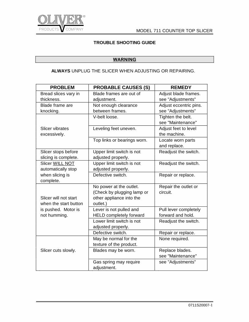
PROBLEM PROBABLE CAUSES (S) REMEDY Bread slices vary in Blade frames are out of Adjust blade frames. thickness. adjustment. see "Adjustments" Blade frame are Not enough clearance Adjust eccentric pins. knocking. between frames. see "Adjustments" V-belt loose. Tighten the belt. see "Maintenance" Slicer vibrates Leveling feet uneven. Adjust feet to level excessively. the machine. Top links or bearings worn. Locate worn parts and replace. Slicer stops before Upper limit switch is not Readjust the switch. slicing is complete. adjusted properly. Slicer WILL NOT Upper limit switch is not Readjust the switch. automatically stop adjusted properly. when slicing is Defective switch. Repair or replace. complete. No power at the outlet. Repair the outlet or (Check by plugging lamp or circuit. Slicer will not start other appliance into the when the start button outlet.) is pushed. Motor is Lever is not pulled and Pull lever completely not humming. HELD completely forward forward and hold. Lower limit switch is not Readjust the switch. adjusted properly. Defective switch. Repair or replace. May be normal for the None required. texture of the product. Slicer cuts slowly. Blades may be worn. Replace blades. see "Maintenance" Gas spring may require see "Adjustments" adjustment.
MODEL 711 COUNTER TOP SLICER
0711S20007-2
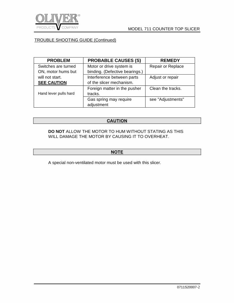
TROUBLE SHOOTING GUIDE (Continued)
PROBLEM PROBABLE CAUSES (S) REMEDY Switches are turned Motor or drive system is Repair or Replace ON, motor hums but binding. (Defective bearings.) will not start. Interference between parts Adjust or repair SEE CAUTION of the slicer mechanism. Foreign matter in the pusher Clean the tracks. Hand lever pulls hard tracks. Gas spring may require see "Adjustments" adjustment
CAUTION DO NOT ALLOW THE MOTOR TO HUM WITHOUT STATING AS THIS WILL DAMAGE THE MOTOR BY CAUSING IT TO OVERHEAT.
NOTE A special non-ventilated motor must be used with this slicer.
MODEL 711 COUNTER TOP SLICER
Rev. 8/23/04 0711S20012
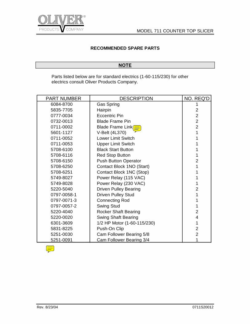
RECOMMENDED SPARE PARTS
NOTE Parts listed below are for standard electrics (1-60-115/230) for other electrics consult Oliver Products Company.
PART NUMBER DESCRIPTION NO. REQ'D6084-8700 Gas Spring 1 5835-7705 Hairpin 2 0777-0034 Eccentric Pin 2 0732-0013 Blade Frame Pin 2 0711-0002 Blade Frame Link 2 5601-1127 V-Belt (4L370) 1 0711-0052 Lower Limit Switch 1 0711-0053 Upper Limit Switch 1 5708-6100 Black Start Button 1 5708-6116 Red Stop Button 1 5708-6150 Push Button Operator 2 5708-6250 Contact Block 1NO (Start) 1 5708-6251 Contact Block 1NC (Stop) 1 5749-8027 Power Relay (115 VAC) 1 5749-8028 Power Relay (230 VAC) 1 5220-5040 Driven Pulley Bearing 2 0797-0058-1 Driven Pulley Stud 1 0797-0071-3 Connecting Rod 1 0797-0057-2 Swing Stud 1 5220-4040 Rocker Shaft Bearing 2 5220-0020 Swing Shaft Bearing 4 6301-3609 1/2 HP Motor (1-60-115/230) 1 5831-8225 Push-On Clip 2 5251-0030 Cam Follower Bearing 5/8 2 5251-0091 Cam Follower Bearing 3/4 1
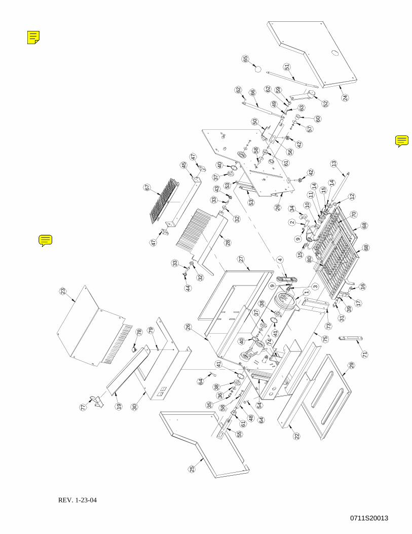
0711S20013
74
71
1977 35
3638
4158
25
30
64
4861
64
55 22
54
29
23
62 596266
24
5260
15
1480
75
2
28
44
78 79 26
47
32
33
9 3
3837
40
41
1
27 4
159
4043
3733
47
67
45 61
5853
32
53
11
3426 1042
49
50
57
42
56
63
6816
31
73
39
1768
1314
7012
65
51
REV. 1-23-04
MODEL 711 COUNTER TOP SLICER
0711S20008-1
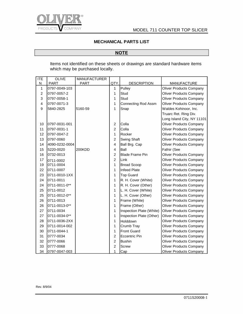
MECHANICAL PARTS LIST
NOTE
Items not identified on these sheets or drawings are standard hardware items which may be purchased locally.
Rev. 8/9/04
ITE OLIVE MANUFACTURERN PART PART QTY. DESCRIPTION MANUFACTURE1 0797-0049-103 1 Pulley Oliver Products Company2 0797-0057-2 1 Stud Oliver Products Company3 0797-0058-1 1 Stud Oliver Products Company4 0797-0071-3 1 Connecting Rod Assm Oliver Products Company9 5840-2825 5160-59 1 Snap Waldes Kohinoor, Inc.
Truarc Ret. Ring Div.Long Island City, NY 11101
10 0797-0031-001 2 Colla Oliver Products Company11 0797-0031-1 2 Colla Oliver Products Company12 0797-0047-2 1 Rocker Oliver Products Company13 0797-0060 2 Swing Shaft Oliver Products Company14 4090-0232-0004 4 Ball Brg. Cap Oliver Products Company15 5220-0020 200KDD 4 Ball Fafnir (See 16 0732-0013 2 Blade Frame Pin Oliver Products Company17 0711-0002 2 Link Oliver Products Company19 0711-0004 1 Bread Scoop Oliver Products Company22 0711-0007 1 Infeed Plate Oliver Products Company23 0711-0010-1XX 1 Top Guard Oliver Products Company24 0711-0011 1 R. H. Cover (White) Oliver Products Company24 0711-0011-0** 1 R. H. Cover (Other) Oliver Products Company25 0711-0012 1 L. H. Cover (White) Oliver Products Company25 0711-0012-0** 1 L. H. Cover (Other) Oliver Products Company26 0711-0013 1 Frame (White) Oliver Products Company26 0711-0013-0** 1 Frame (Other) Oliver Products Company27 0711-0034 1 Inspection Plate (White) Oliver Products Company27 0711-0034-0** 1 Inspection Plate (Other) Oliver Products Company28 0711-0036-2XX 1 Holddown Oliver Products Company29 0711-0014-002 1 Crumb Tray Oliver Products Company30 0711-0044-1 1 Front Guard Oliver Products Company31 0777-0034 2 Eccentric Pin Oliver Products Company32 0777-0066 2 Bushin Oliver Products Company33 0777-0068 2 Screw Oliver Products Company34 0797-0047-003 1 Cap Oliver Products Company
MODEL 711 COUNTER TOP SLICER
0711S20008-2
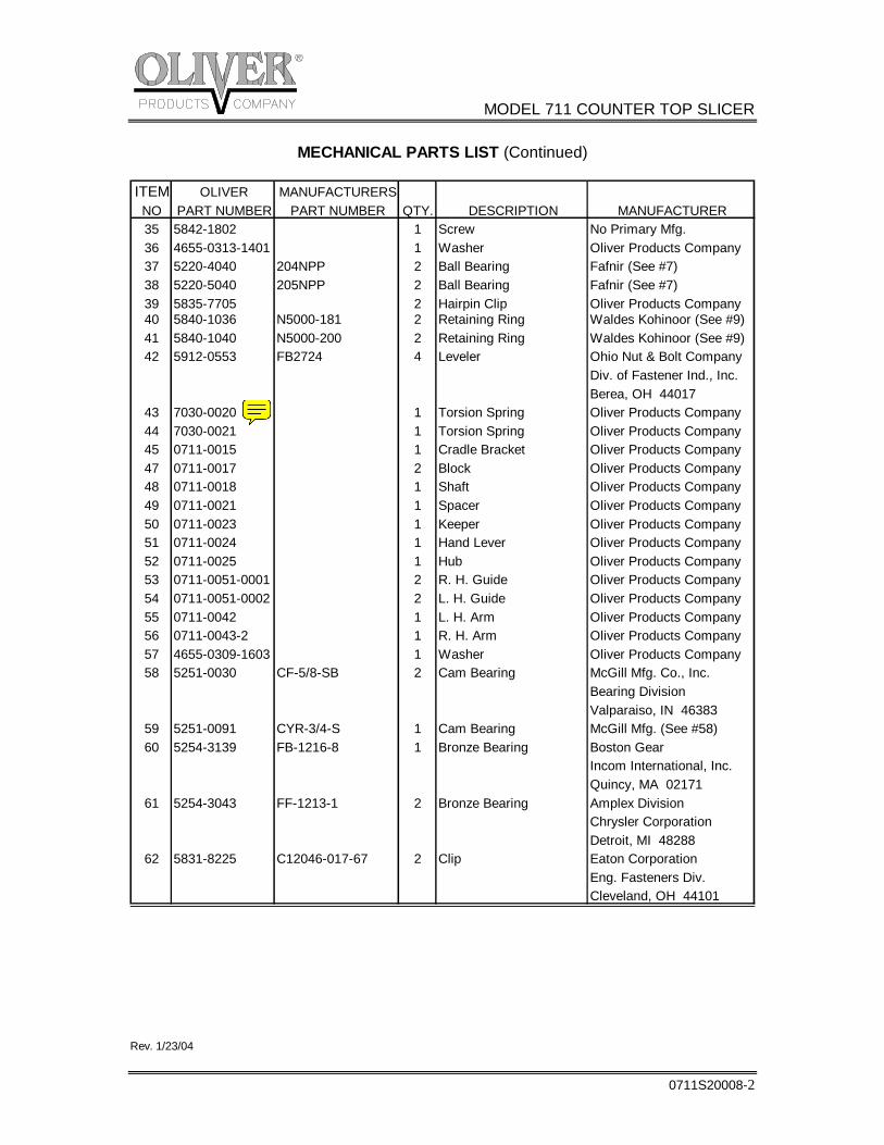
MECHANICAL PARTS LIST (Continued)
Rev. 1/23/04
ITEM OLIVER MANUFACTURERSNO PART NUMBER PART NUMBER QTY. DESCRIPTION MANUFACTURER35 5842-1802 1 Screw No Primary Mfg. 36 4655-0313-1401 1 Washer Oliver Products Company37 5220-4040 204NPP 2 Ball Bearing Fafnir (See #7) 38 5220-5040 205NPP 2 Ball Bearing Fafnir (See #7) 39 5835-7705 2 Hairpin Clip Oliver Products Company40 5840-1036 N5000-181 2 Retaining Ring Waldes Kohinoor (See #9)41 5840-1040 N5000-200 2 Retaining Ring Waldes Kohinoor (See #9)42 5912-0553 FB2724 4 Leveler Ohio Nut & Bolt Company
Div. of Fastener Ind., Inc.Berea, OH 44017
43 7030-0020 1 Torsion Spring Oliver Products Company44 7030-0021 1 Torsion Spring Oliver Products Company45 0711-0015 1 Cradle Bracket Oliver Products Company47 0711-0017 2 Block Oliver Products Company48 0711-0018 1 Shaft Oliver Products Company49 0711-0021 1 Spacer Oliver Products Company50 0711-0023 1 Keeper Oliver Products Company51 0711-0024 1 Hand Lever Oliver Products Company52 0711-0025 1 Hub Oliver Products Company53 0711-0051-0001 2 R. H. Guide Oliver Products Company54 0711-0051-0002 2 L. H. Guide Oliver Products Company55 0711-0042 1 L. H. Arm Oliver Products Company56 0711-0043-2 1 R. H. Arm Oliver Products Company57 4655-0309-1603 1 Washer Oliver Products Company58 5251-0030 CF-5/8-SB 2 Cam Bearing McGill Mfg. Co., Inc.
Bearing Division Valparaiso, IN 46383
59 5251-0091 CYR-3/4-S 1 Cam Bearing McGill Mfg. (See #58)60 5254-3139 FB-1216-8 1 Bronze Bearing Boston Gear
Incom International, Inc.Quincy, MA 02171
61 5254-3043 FF-1213-1 2 Bronze Bearing Amplex Division Chrysler CorporationDetroit, MI 48288
62 5831-8225 C12046-017-67 2 Clip Eaton Corporation Eng. Fasteners Div. Cleveland, OH 44101
MODEL 711 COUNTER TOP SLICER
0711S20008-3
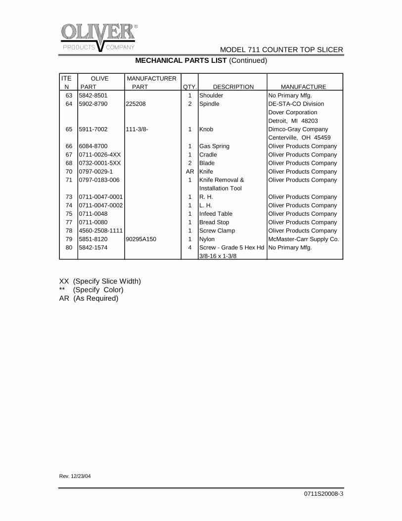
MECHANICAL PARTS LIST (Continued)
XX (Specify Slice Width) ** (Specify Color) AR (As Required) Rev. 12/23/04
ITE OLIVE MANUFACTURERN PART PART QTY. DESCRIPTION MANUFACTURE63 5842-8501 1 Shoulder No Primary Mfg. 64 5902-8790 225208 2 Spindle DE-STA-CO Division
Dover Corporation Detroit, MI 48203
65 5911-7002 111-3/8- 1 Knob Dimco-Gray CompanyCenterville, OH 45459
66 6084-8700 1 Gas Spring Oliver Products Company67 0711-0026-4XX 1 Cradle Oliver Products Company68 0732-0001-5XX 2 Blade Oliver Products Company70 0797-0029-1 AR Knife Oliver Products Company71 0797-0183-006 1 Knife Removal & Oliver Products Company
Installation Tool73 0711-0047-0001 1 R. H. Oliver Products Company74 0711-0047-0002 1 L. H. Oliver Products Company75 0711-0048 1 Infeed Table Oliver Products Company77 0711-0080 1 Bread Stop Oliver Products Company78 4560-2508-1111 1 Screw Clamp Oliver Products Company79 5851-8120 90295A150 1 Nylon McMaster-Carr Supply Co.80 5842-1574 4 Screw - Grade 5 Hex Hd No Primary Mfg.
3/8-16 x 1-3/8
MODEL 711 COUNTER TOP SLICER
0711S20009-1
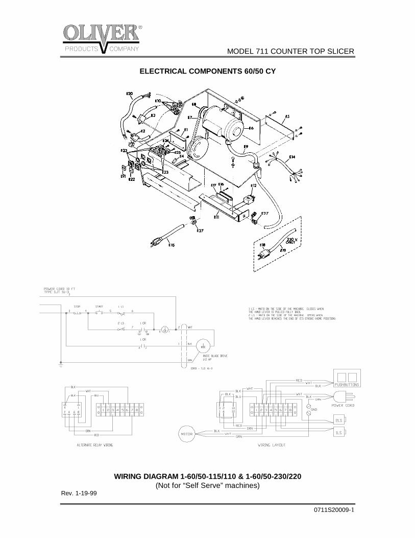
ELECTRICAL COMPONENTS 60/50 CY
WIRING DIAGRAM 1-60/50-115/110 & 1-60/50-230/220 (Not for “Self Serve” machines)
Rev. 1-19-99
MODEL 711 COUNTER TOP SLICER
0711S20009-2
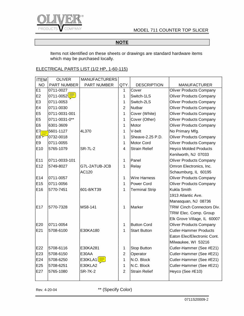
NOTE
Items not identified on these sheets or drawings are standard hardware items which may be purchased locally. ELECTRICAL PARTS LIST (1/2 HP, 1-60-115)
ITEM OLIVER MANUFACTURERS NO PART NUMBER PART NUMBER QTY. DESCRIPTION MANUFACTURER
E1 0711-0027 1 Cover Oliver Products Company E2 0711-0052 1 Switch-1LS Oliver Products Company E3 0711-0053 1 Switch-2LS Oliver Products Company E4 0711-0030 2 Nutbar Oliver Products Company E5 0711-0031-001 1 Cover (White) Oliver Products Company E5 0711-0031-0** 1 Cover (Other) Oliver Products Company E6 6301-3609 1 Motor Oliver Products Company E7 5601-1127 4L370 1 V-belt No Primary Mfg. E8 0732-0018 1 Sheave-2.25 P.D. Oliver Products Company E9 0711-0055 1 Motor Cord Oliver Products Company E10 5765-1079 SR-7L-2 4 Strain Relief Heyco Molded Products Kenilworth, NJ 07033 E11 0711-0033-101 1 Panel Oliver Products Company E12 5749-8027 G7L-2ATUB-JCB 1 Relay Omron Electronics, Inc. AC120 Schaumburg, IL 60195 E14 0711-0057 1 Wire Harness Oliver Products Company E15 0711-0056 1 Power Cord Oliver Products Company E16 5770-7451 601-8/KT39 1 Terminal Strip Kukla Smith 1913 Atlantic Ave. Manasquan, NJ 08736 E17 5770-7328 MS8-141 1 Marker TRW Cinch Connectors Div. TRW Elec. Comp. Group Elk Grove Village, IL 60007E20 0711-0054 1 Button Cord Oliver Products Company E21 5708-6100 E30KA180 1 Start Button Cutler-Hammer Products Eaton Elec/Electronic Cont. Milwaukee, WI 53216 E22 5708-6116 E30KA281 1 Stop Button Cutler-Hammer (See #E21) E23 5708-6150 E30AA 2 Operator Cutler-Hammer (See #E21) E24 5708-6250 E30KLA1 1 N.O. Block Cutler-Hammer (See #E21) E25 5708-6251 E30KLA2 1 N.C. Block Cutler-Hammer (See #E21) E27 5765-1080 SR-7K-2 2 Strain Relief Heyco (See #E10) Rev. 4-20-04 ** (Specify Color)
MODEL 711 COUNTER TOP SLICER
0711S20009-3
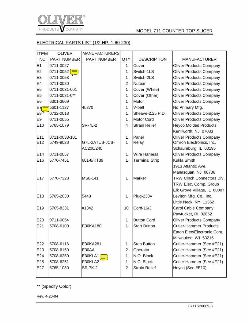
ELECTRICAL PARTS LIST (1/2 HP, 1-60-230)
ITEM OLIVER MANUFACTURERS NO PART NUMBER PART NUMBER QTY. DESCRIPTION MANUFACTURER
E1 0711-0027 1 Cover Oliver Products Company E2 0711-0052 1 Switch-1LS Oliver Products Company E3 0711-0053 1 Switch-2LS Oliver Products Company E4 0711-0030 2 Nutbar Oliver Products Company E5 0711-0031-001 1 Cover (White) Oliver Products Company E5 0711-0031-0** 1 Cover (Other) Oliver Products Company E6 6301-3609 1 Motor Oliver Products Company E7 5601-1127 4L370 1 V-belt No Primary Mfg. E8 0732-0018 1 Sheave-2.25 P.D. Oliver Products Company E9 0711-0055 1 Motor Cord Oliver Products Company E10 5765-1079 SR-7L-2 4 Strain Relief Heyco Molded Products Kenilworth, NJ 07033 E11 0711-0033-101 1 Panel Oliver Products Company E12 5749-8028 G7L-2ATUB-JCB- 1 Relay Omron Electronics, Inc. AC200/240 Schaumburg, IL 60195 E14 0711-0057 1 Wire Harness Oliver Products Company E16 5770-7451 601-8/KT39 1 Terminal Strip Kukla Smith 1913 Atlantic Ave. Manasquan, NJ 08736 E17 5770-7328 MS8-141 1 Marker TRW Cinch Connectors Div. TRW Elec. Comp. Group Elk Grove Village, IL 60007E18 5765-2030 5443 1 Plug-230V Leviton Mfg. Co., Inc. Little Neck, NY 11362 E19 5765-8331 #1342 10' Cord-16/3 Carol Cable Company Pawtucket, RI 02862 E20 0711-0054 1 Button Cord Oliver Products Company E21 5708-6100 E30KA180 1 Start Button Cutler-Hammer Products Eaton Elec/Electronic Cont. Milwaukee, WI 53216 E22 5708-6116 E30KA281 1 Stop Button Cutler-Hammer (See #E21) E23 5708-6150 E30AA 2 Operator Cutler-Hammer (See #E21) E24 5708-6250 E30KLA1 1 N.O. Block Cutler-Hammer (See #E21) E25 5708-6251 E30KLA2 1 N.C. Block Cutler-Hammer (See #E21) E27 5765-1080 SR-7K-2 2 Strain Relief Heyco (See #E10) ** (Specify Color) Rev. 4-20-04
MODEL 711 COUNTER TOP SLICER
0711S20009-4
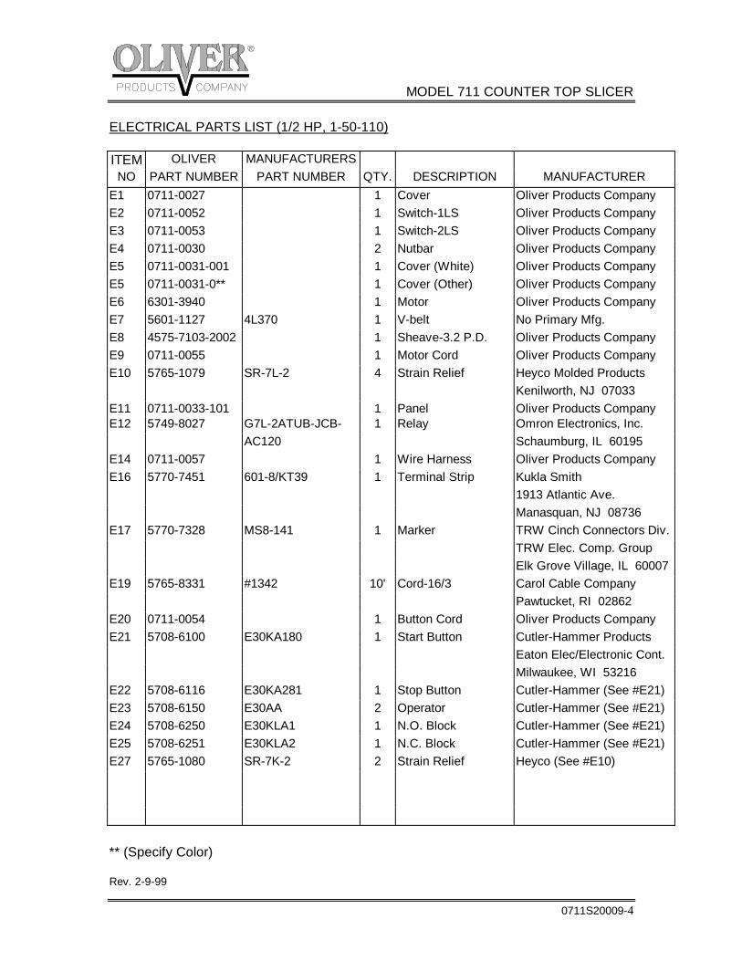
ELECTRICAL PARTS LIST (1/2 HP, 1-50-110)
ITEM OLIVER MANUFACTURERS NO PART NUMBER PART NUMBER QTY. DESCRIPTION MANUFACTURER
E1 0711-0027 1 Cover Oliver Products Company E2 0711-0052 1 Switch-1LS Oliver Products Company E3 0711-0053 1 Switch-2LS Oliver Products Company E4 0711-0030 2 Nutbar Oliver Products Company E5 0711-0031-001 1 Cover (White) Oliver Products Company E5 0711-0031-0** 1 Cover (Other) Oliver Products Company E6 6301-3940 1 Motor Oliver Products Company E7 5601-1127 4L370 1 V-belt No Primary Mfg. E8 4575-7103-2002 1 Sheave-3.2 P.D. Oliver Products Company E9 0711-0055 1 Motor Cord Oliver Products Company E10 5765-1079 SR-7L-2 4 Strain Relief Heyco Molded Products Kenilworth, NJ 07033 E11 0711-0033-101 1 Panel Oliver Products Company E12 5749-8027 G7L-2ATUB-JCB- 1 Relay Omron Electronics, Inc. AC120 Schaumburg, IL 60195 E14 0711-0057 1 Wire Harness Oliver Products Company E16 5770-7451 601-8/KT39 1 Terminal Strip Kukla Smith 1913 Atlantic Ave. Manasquan, NJ 08736 E17 5770-7328 MS8-141 1 Marker TRW Cinch Connectors Div. TRW Elec. Comp. Group Elk Grove Village, IL 60007E19 5765-8331 #1342 10' Cord-16/3 Carol Cable Company Pawtucket, RI 02862 E20 0711-0054 1 Button Cord Oliver Products Company E21 5708-6100 E30KA180 1 Start Button Cutler-Hammer Products Eaton Elec/Electronic Cont. Milwaukee, WI 53216 E22 5708-6116 E30KA281 1 Stop Button Cutler-Hammer (See #E21) E23 5708-6150 E30AA 2 Operator Cutler-Hammer (See #E21) E24 5708-6250 E30KLA1 1 N.O. Block Cutler-Hammer (See #E21) E25 5708-6251 E30KLA2 1 N.C. Block Cutler-Hammer (See #E21) E27 5765-1080 SR-7K-2 2 Strain Relief Heyco (See #E10) ** (Specify Color) Rev. 2-9-99
MODEL 711 COUNTER TOP SLICER
0711S20009-5
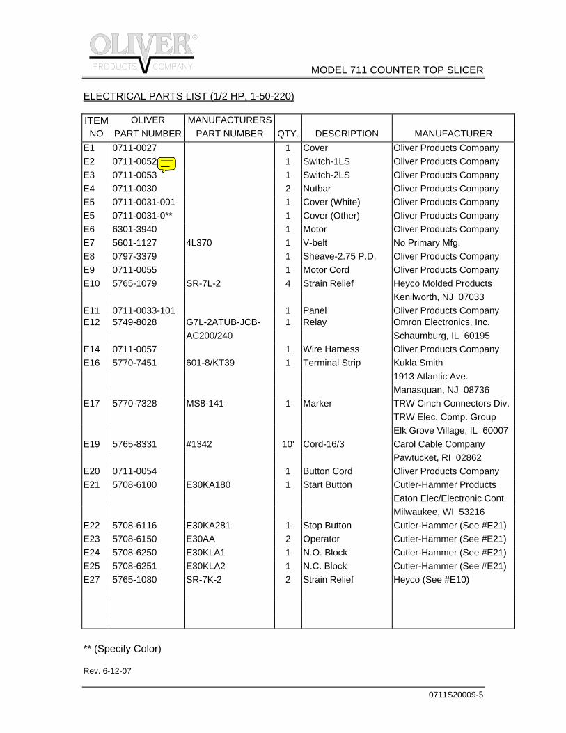
ELECTRICAL PARTS LIST (1/2 HP, 1-50-220)
ITEM OLIVER MANUFACTURERS
NO PART NUMBER PART NUMBER QTY. DESCRIPTION MANUFACTURER E1 0711-0027 1 Cover Oliver Products Company E2 0711-0052 1 Switch-1LS Oliver Products Company E3 0711-0053 1 Switch-2LS Oliver Products Company E4 0711-0030 2 Nutbar Oliver Products Company E5 0711-0031-001 1 Cover (White) Oliver Products Company E5 0711-0031-0** 1 Cover (Other) Oliver Products Company E6 6301-3940 1 Motor Oliver Products Company E7 5601-1127 4L370 1 V-belt No Primary Mfg. E8 0797-3379 1 Sheave-2.75 P.D. Oliver Products Company E9 0711-0055 1 Motor Cord Oliver Products Company E10 5765-1079 SR-7L-2 4 Strain Relief Heyco Molded Products Kenilworth, NJ 07033 E11 0711-0033-101 1 Panel Oliver Products Company E12 5749-8028 G7L-2ATUB-JCB- 1 Relay Omron Electronics, Inc. AC200/240 Schaumburg, IL 60195 E14 0711-0057 1 Wire Harness Oliver Products Company E16 5770-7451 601-8/KT39 1 Terminal Strip Kukla Smith 1913 Atlantic Ave. Manasquan, NJ 08736 E17 5770-7328 MS8-141 1 Marker TRW Cinch Connectors Div. TRW Elec. Comp. Group Elk Grove Village, IL 60007 E19 5765-8331 #1342 10' Cord-16/3 Carol Cable Company Pawtucket, RI 02862 E20 0711-0054 1 Button Cord Oliver Products Company E21 5708-6100 E30KA180 1 Start Button Cutler-Hammer Products Eaton Elec/Electronic Cont. Milwaukee, WI 53216 E22 5708-6116 E30KA281 1 Stop Button Cutler-Hammer (See #E21) E23 5708-6150 E30AA 2 Operator Cutler-Hammer (See #E21) E24 5708-6250 E30KLA1 1 N.O. Block Cutler-Hammer (See #E21) E25 5708-6251 E30KLA2 1 N.C. Block Cutler-Hammer (See #E21) E27 5765-1080 SR-7K-2 2 Strain Relief Heyco (See #E10) ** (Specify Color) Rev. 6-12-07
MODEL 711 COUNTER TOP BREAD SLICER
0711S20011-1
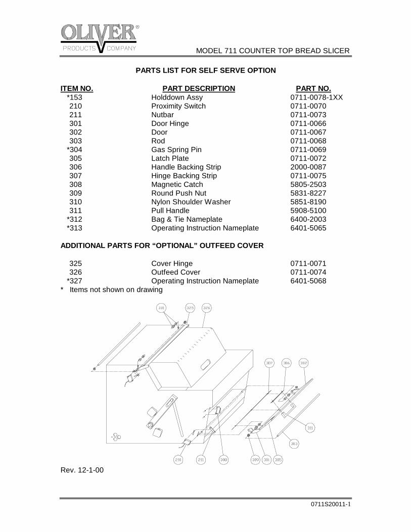
PARTS LIST FOR SELF SERVE OPTION
ITEM NO. PART DESCRIPTION PART NO. *153 Holddown Assy 0711-0078-1XX 210 Proximity Switch 0711-0070 211 Nutbar 0711-0073 301 Door Hinge 0711-0066 302 Door 0711-0067 303 Rod 0711-0068 *304 Gas Spring Pin 0711-0069 305 Latch Plate 0711-0072 306 Handle Backing Strip 2000-0087 307 Hinge Backing Strip 0711-0075 308 Magnetic Catch 5805-2503 309 Round Push Nut 5831-8227 310 Nylon Shoulder Washer 5851-8190 311 Pull Handle 5908-5100 *312 Bag & Tie Nameplate 6400-2003 *313 Operating Instruction Nameplate 6401-5065 ADDITIONAL PARTS FOR “OPTIONAL” OUTFEED COVER 325 Cover Hinge 0711-0071 326 Outfeed Cover 0711-0074 *327 Operating Instruction Nameplate 6401-5068 * Items not shown on drawing
Rev. 12-1-00
MODEL 711 COUNTER TOP BREAD SLICER
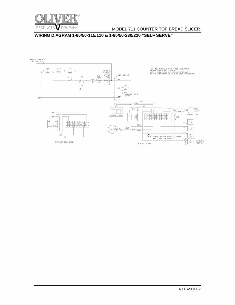
0711S20011-2
WIRING DIAGRAM 1-60/50-115/110 & 1-60/50-230/220 “SELF SERVE”
GEN 040225
WARRANTYPARTSOliver Products Company (Oliver) warrants that if any part of the equipment (other than a part not manufactured by Oliver) proves to be defective (as defined below) within one year after shipment, and if Buyer returns the defective part to Oliver within one year, Freight Prepaid to Oliver’s plant in Grand Rapids, MI, then Oliver, shall, at Oliver’s option, either repair or replace the defective part, at Oliver’s expense.
LABOROliver further warrants that equipment properly installed in accordance with our special instructions, which proves to be defective in material or workmanship under normal use within one (1) year from installation or one (1) year and three (3) months from actual shipment date, whichever date comes first, will be repaired by Oliver or an Oliver Authorized Service Dealer, in accordance with Oliver’s published Service Schedule.
For purposes of this warranty, a defective part or defective equipment is a part or equipment which is found by Oliver to have been defective in materials workmanship, if the defect materially impairs the value of the equipment to Buyer. Oliver has no obligation as to parts or components not manufactured by Oliver, but Oliver assigns to Buyer any warranties made to Oliver by the manufacturer thereof.
This warranty does not apply to: 1. Damage caused by shipping or accident. 2. Damage resulting from improper installation or alteration. 3. Equipment misused, abused, altered, not maintained on a regular basis, operated carelessly, or used in abnormal conditions. 4. Equipment used in conjunction with products of other manufacturers unless such use is approved by Oliver Products in writing. 5. Periodic maintenance of equipment, including but not limited to lubrication, replacement of wear
items, and other adjustments required due to installation, set up, or normal wear. 6. Losses or damage resulting from malfunction.
The foregoing warranty is in lieu of all other warranties expressed or implied AND OLIVER MAKES NO WARRANTY OF MERCHANTABILITY OR FITNESS FOR PURPOSE REGARDING THE EQUIPMENT COVERED BY THIS WARRANTY. Oliver neither assumes nor authorizes any person to assume for it any other obligations or liability in connection with said equipment. OLIVER SHALL NOT BE LIABLE FOR LOSS OF TIME, INCONVENIENCE, COMMERCIAL LOSS, INCIDENTAL OR CONSEQUENTIAL DAMAGES.
GEN 040226
WARRANTY PROCEDURE
1. If a problem should occur, either the dealer or the end user must contact the Customer Service Department and explain the problem.
2. The Customer Service Manager will determine if the warranty will apply to this particular problem.
3. If the Customer Service Manager approves, a Work Authorization Number will be generated, and the appropriate service agency will perform the service.
4. The service dealer will then complete an invoice and send it to the Customer Service Department at Oliver Products Company.
5. The Customer Service Manager of Oliver Products Company will review the invoice and returned parts, if applicable, and approve for payment.
GEN 040227
RETURNED PARTS POLICY
This policy applies to all parts returned to the factory whether for warranted credit, replacement, repair or re-stocking.
Oliver Products Company requires that the customer obtain a Return Material Authorization (RMA) number before returning any part. This number should appear on the shipping label and inside the shipping carton as well. All parts are to be returned prepaid. Following this procedure will insure prompt handling of all returned parts.
To obtain an RMA number contact the Repair Parts Deptartment toll free at (800) 253-3893.
Parts returned for re-stocking are subject to a RE-STOCKING CHARGE.
Thank you for your cooperation,
Repair Parts Manager Oliver Products Company