Embed Size (px)
Citation preview
PI
som med tioffentlig grmaj 2010, kförsvaras påde Ciencia y
POLYMIN THI
illstånd av Kranskning fökl 10.00 i sal å engelska. FTecnología de
MER NIN FILM
Linda
AKADEM
Kungliga Tekör avläggandD1, LindsteFakultetsoppe Polímeros (I
NANOC
M APP
a Fogelst
MISK AVHAN
kniska högskde av tekniskdtsvägen 17,ponent: ProfeICTP‐CSIC), M
COMPO
PLICAT
tröm
NDLING
kolan i Stockk doktorsexa, KTH, Stockessor José MMadrid, Span
OSITES TIONS
kholm framlamen fredagkholm. Avha
M. Kenny frånnien.
lägges till gen den 7 andlingen n Instituto
Copyright © 2010 Linda Fogelström All rights reserved Paper I © 2006 Elsevier B.V. Paper V © 2008 Elsevier B.V. TRITA‐CHE‐Report 2010:12 ISSN 1654‐1081 ISBN 978‐91‐7415‐615‐7
ABSTRACT
The introduction of a nanoscopic reinforcing phase to a polymer matrix offers great possibilities of obtaining improved properties, enabling applications outside the boundaries of traditional composites.
The majority of the work in this thesis has been devoted to polymer/clay nanocomposites in coating applications, using the hydroxyl‐functional hyperbranched polyester Boltorn® as matrix and montmorillonite clay as nanofiller. Nanocomposites with a high degree of exfoliation were readily prepared using the straightforward solution‐intercalation method with water as solvent. Hard and scratch‐resistant coatings with preserved flexibility and transparency were obtained, and acrylate functionalization of Boltorn® rendered a UV‐curable system with similar property improvements. In order to elucidate the effect of the dendritic architecture on the exfoliation process, a comparative study on the hyperbranched polyester Boltorn® and a linear analogue of this polymer was performed. X‐ray diffraction and transmission electron microscopy confirmed the superior efficiency of the hyperbranched polymer in the preparation of this type of nanocomposites.
Additionally, an objective of this thesis was to investigate how cellulose nanofibers can be utilized in high performance polymer nanocomposites. A reactive cellulose “nanopaper” template was combined with a hydrophilic hyperbranched thermoset matrix, resulting in a unique nanocomposite with significantly enhanced properties. Moreover, in order to fully utilize the great potential of cellulose nanofibers as reinforcement in hydrophobic polymer matrices, the hydrophilic surface of cellulose needs to be modified in order to improve the compatibility. For this, a grafting‐from approach was explored, using ring‐opening polymerization of ε‐caprolactone (CL) from microfibrillated cellulose (MFC), resulting in PCL‐modified MFC. It was found that the hydrophobicity of the cellulose surfaces increased with longer graft lengths, and that polymer grafting rendered a smoother surface morphology. Subsequently, PCL‐grafted MFC film/PCL film bilayer laminates were prepared in order to investigate the interfacial adhesion. Peel tests demonstrated a gradual increase in the interfacial adhesion with increasing graft lengths.
SAMMANFATTNING
Tillförandet av en förstärkande fas i nanostorlek till en polymermatris innebär stora möjligheter till egenskapsförbättringar, vilket möjliggör användande utanför ramarna för traditionella kompositer.
Majoriteten av arbetet i denna avhandling har tillägnats polymer/lera‐nanokompositer i lackapplikationer, i vilka den hydroxyl‐funktionella hyper‐förgrenade polyestern Boltorn® har använts som matris och montorillonit‐lera som nanofyllmedel. Nanokompositer med hög grad av exfoliering kunde relativt enkelt framställas genom att använda den okomplicerade lösningsmedels‐interkaleringsmetoden, med vatten som lösningsmedel. Hårda och reptåliga lacker med bevarad flexibilitet och transparens erhölls och akrylat‐funktionalisering av Boltorn® gav ett UV‐härdbart system med liknande egenskapsförbättringar. För att klarlägga vilken effekt den dendritiska strukturen har på exfolieringsprocessen, gjordes en jämförelsestudie mellan den hyper‐förgrenade polyestern Boltorn® och en linjär analog till denna polymer. Röntgendiffraktion och transmissionselektronmikroskopi bekräftade den överlägsna förmågan hos den hyperförgrenade polymeren i framställandet av denna typ av nanokompositer. Vidare var målet med denna avhandling att undersöka hur nanofibrer av
cellulosa kan användas i polymera nanokompositer med hög prestanda. Ett reaktivt ”nanopappers”‐templat bestående av cellulosananofibrer kombinerades med en hydrofil hyperförgrenad härdplastmatris, vilket resulterade i en unik nanokomposit med signifikant förbättrade egenskaper. För att till fullo kunna utnyttja den stora potentialen hos cellulosananofibrer som förstärkare i hydrofoba polymermatriser, måste cellulosans hydrofila yta modifieras för att öka kompatibiliteten. För detta ändamål undersöktes ringöppningspolymerisation som metod att ympa poly(ε‐kaprolakton) (PCL) från mikrofibrillerad cellulosa (MFC). Resultaten visade att hydrofobiciteten hos cellulosaytan ökade med längden av den ympade polymeren och att polymer‐ympningen gav en slätare ytmorfologi. För att undersöka vidhäftningen mellan gränsytorna framställdes laminat av PCL‐ympade MFC‐filmer och rena PCL‐filmer. Analys av dessa visade att vidhäftningen mellan gränsytorna successivt ökade med växande ymplängder.
LIST OF PAPERS The thesis is a summary of the following papers:
I. ”UV‐curable Hyperbranched Nanocomposite Coatings” L. Fogelström, P. Antoni, E. Malmström, A. Hult, Progress in Organic Coatings 2006, 55, 284–290.
II. “Hard and Flexible Nanocomposite Coatings using Nanoclay‐filled Hyperbranched Polymers” L. Fogelström, E. Malmström, M. Johansson, A. Hult, ACS Applied Materials & Interfaces, submitted
III. ʺLinear vs. Hyperbranched Polymers in the Preparation of Polymer/Clay Nanocomposites” L. Fogelström, S. Hansson, A. Carlmark, A. Hult, E. Malmström, Polymer, submitted
IV. “Novel Nanocomposite Concept based on Hyperbranched Polymers in Reactive Cellulose Nanopaper Templates” M. Henriksson, L. Fogelström, M. Johansson, A. Hult, L. Berglund, Composites Science and Technology, submitted
V. ʺSurface Grafting of Microfibrillated Cellulose with Poly(ε‐caprolactone) – Synthesis and Characterization” H. Lönnberg, L. Fogelström, Q. Zhou, A. Hult, L. Berglund, E. Malmström, European Polymer Journal 2008, 44, 2991–2997
VI. “Investigation of the Graft‐Length Impact on the Interfacial Toughness in a Cellulose/Poly(ε‐caprolactone) Bilayer Laminate” H. Lönnberg, L. Fogelström, Q. Zhou, A. Hult, L. Berglund, E. Malmström, Composites Science and Technology, submitted
The contributions of the author of this thesis to the appended papers are: I. The majority of the experimental work and most of the preparation of the
manuscript. II. All of the experimental work and the preparation of the manuscript. III. The majority of the experimental work and most of the preparation of the
manuscript. IV. Half of the experimental work and the preparation of the manuscript.
Involved in all parts of the work. V. Minor parts of the experimental work and the preparation of the manuscript. VI. About half of the experimental work and minor parts of the preparation of
the manuscript. Papers not included in this thesis:
VII. ʺEnzymatic One‐Pot Route to Telechelic Polypentadecalactone Epoxide: Synthesis, UV Curing, and Characterization” M. Eriksson, L. Fogelström, K. Hult, E. Malmström, M. Johansson, S. Trey, M. Martinelle, Biomacromolecules 2009, 10(11), 3108‐3113
VIII. “Honeycomb‐Patterned Membranes from Polymer‐Modified Silica Nanoparticles” D. Nyström, P. Antoni, E. Östmark, D. Nordqvist, J. Örtegren, L. Fogelström, E. Malmström, M. Lindgren, A. Hult, manuscript
ABBREVIATIONS
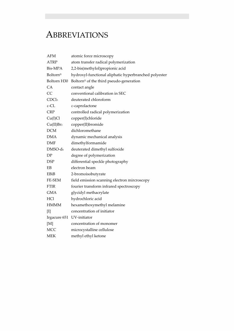
AFM atomic force microscopy ATRP atom transfer radical polymerization Bis‐MPA 2,2‐bis(methylol)propionic acid Boltorn® hydroxyl‐functional aliphatic hyperbranched polyester Boltorn H30 Boltorn® of the third pseudo‐generation CA contact angle CC conventional calibration in SEC CDCl3 deuterated chloroform ε‐CL ε‐caprolactone CRP controlled radical polymerization Cu(I)Cl copper(I)chloride Cu(II)Br2 copper(II)bromide DCM dichloromethane DMA dynamic mechanical analysis DMF dimethylformamide DMSO‐d6 deuterated dimethyl sulfoxide DP degree of polymerization DSP differential speckle photography EB electron beam EBiB 2‐bromoisobutyrate FE‐SEM field emission scanning electron mircroscopy FTIR fourier transform infrared spectroscopy GMA glycidyl methacrylate HCl hydrochloric acid HMMM hexamethoxymethyl melamine [I] concentration of initiator Irgacure 651 UV‐initiator [M] concentration of monomer MCC microcystalline cellulose MEK methyl ethyl ketone
MFC microfibrillated cellulose MMT montmorillonite Mn number average molecular weight MW molecular weight Na+MMT natural montmorillonite NMP nitroxide mediated polymerization NMR nuclear magnetic resonance spectroscopy PCL poly(ε‐caprolactone) PDI polydispersity index PGMA poly(glycidyl methacrylate) PMDETA pentamethyldiethyltriamine pTSA p‐toluenesulfonic acid RAFT reversible addition fragmentation chain transfer polymerization RH relative humidity ROP ring‐opening polymerization RT room temperature SEC size exclusion chromatography Sn(Oct)2 tin octoate std standard deviation tan δ storage modulus/loss modulus in DMA TBAB tetrabutyl ammonium bromide TEM transmission electron microscopy Texanol 2,2,4‐trimethyl‐1,3‐pentanediol monoisobutyrate Tg glass transission temperature TGA thermogravimetric analysis THF tetrahydrofuran TONE 0301 polyol spacer TPGDA tripropyleneglycol diacrylate UC universal calibration in SEC UV ultra violet Vf cellulose nanofiber volume fractions XRD x‐ray diffraction Zcrit critical entanglement chain length
TABLE OF CONTENTS
1. PURPOSE OF THE STUDY .................................................................................... 1
2. INTRODUCTION ..................................................................................................... 2
2.1 POLYMER NANOCOMPOSITES ............................................................................... 2 2.2 POLYMER/CLAY NANOCOMPOSITES...................................................................... 3
2.2.1 Montmorillonite clay .................................................................................... 3 2.2.2 Structure of polymer/clay nanocomposites .................................................. 4 2.2.3 Preparation of polymer/clay nanocomposites ............................................. 5 2.2.4 Characterization of polymer/clay nanocomposites ...................................... 5 2.2.5 Properties of polymer/clay nanocomposites ................................................ 6
2.3 DENDRITIC POLYMERS .......................................................................................... 7 2.3.1 Hyperbranched polymers ............................................................................. 8
2.3.1.1 Properties of hyperbranched polymers ................................................................. 8 2.3.1.2 Derivatization of hyperbranched polymers .......................................................... 9 2.3.1.3 Boltorn® ............................................................................................................... 9
2.4 DENDRITIC POLYMER/CLAY NANOCOMPOSITES ................................................. 10 2.5 CELLULOSE ........................................................................................................ 11
2.5.1 Cellulose nanofibers .................................................................................. 12 2.5.2 Cellulose nanocomposites .......................................................................... 12 2.5.3 Surface modification of cellulose ............................................................... 12
2.6 CONTROLLED POLYMERIZATION ......................................................................... 13 2.6.1 Atom transfer radical polymerization, ATRP ............................................. 14 2.6.2 Ring-opening polymerization, ROP ........................................................... 14
2.7 THIN FILM APPLICATIONS ................................................................................... 15 2.7.1 Coatings ..................................................................................................... 15
2.7.1.1 Coating types ..................................................................................................... 16 2.7.1.2 Rheology of coatings ......................................................................................... 17 2.7.1.3 Dendritic polymers in coatings .......................................................................... 17 2.7.1.4 Nanocomposite coatings .................................................................................... 17
3. EXPERIMENTAL ................................................................................................... 18
3.1 MATERIALS ........................................................................................................ 18 3.2 CHARACTERIZATION METHODS .......................................................................... 18 3.3 EXPERIMENTAL PROCEDURES ............................................................................ 21
3.3.1 Boltorn H30/Na+MMT nanocomposite coatings ....................................... 21 3.3.1.1 Preparation of Boltorn H30/Na+MMT nanocomposites (Paper I and II) ........... 21
3.3.1.2 Preparation of thermally cured coatings (Paper II) ............................................ 21 3.3.2 Acrylated Boltorn H30/Na+MMT nanocomposite coatings ....................... 22
3.3.2.1 Synthesis of acrylated Boltorn H30 ................................................................... 22 3.3.2.2 Preparation of acrylated Boltorn H30/Na+MMT nanocomposites ..................... 22 3.3.2.3 Preparation of UV-cured coatings ...................................................................... 22
3.3.3 Linear vs. hyperbranched polymers in polymer/clay nanocomposites ...... 23 3.3.3.1 Synthesis of PGMA using ATRP....................................................................... 23 3.3.3.2 Synthesis of Bis-MPA-modified PGMA – a linear analogue to Boltorn H30 .... 23 3.3.3.3 Preparation of Boltorn H30/Na+MMT nanocomposites (Paper III) ................... 24 3.3.3.4 Preparation of Bis-MPA-modified PGMA/Na+MMT nanocomposites ............. 24 3.3.3.5 Preparation of thermally cured coatings (Paper III) ........................................... 24
3.3.4 Cellulose nanocomposite films .................................................................. 24 3.3.4.1 Preparation of MFC nanofiber films .................................................................. 24 3.3.4.2 Preparation of MFC nanofiber films for Boltorn H30/MFC nanocomposites .... 24 3.3.4.3 Preparation of Boltorn H30/MFC nanocomposites ............................................ 24
3.3.5 Surface modification of cellulose nanofibers ............................................. 25 3.3.5.1 Grafting of PCL from MFC using ROP ............................................................. 25
3.3.6 Cellulose nanocomposite laminates ........................................................... 26 3.3.6.1 Grafting of PCL from MFC nanofiber films using ROP .................................... 26 3.3.6.2 Preparation of PCL-film and PCL-MFC bilayer laminates ................................ 26
4. RESULTS AND DISCUSSION .............................................................................. 27
4.1 POLYMER/CLAY NANOCOMPOSITES ................................................................... 27 4.1.1 Boltorn H30/Na+MMT nanocomposite coatings ....................................... 27
4.1.1.1 Nanocomposite characterization ........................................................................ 27 4.1.1.2 Coating characterization .................................................................................... 31
4.1.2 Acrylated Boltorn H30/Na+MMT nanocomposite coatings ....................... 34 4.1.2.1 Synthesis of acrylated Boltorn H30 ................................................................... 34 4.1.2.2 Nanocomposite characterization ........................................................................ 35 4.1.2.3 Coating characterization .................................................................................... 37
4.1.3 Linear vs. hyperbranched polymers in polymer/clay nanocomposites ...... 39 4.1.3.1 Synthesis of linear analogue to Boltorn H30 ..................................................... 39 4.1.3.2 Nanocomposite and film preparation ................................................................. 40 4.1.3.3 Nanocomposite characterization ........................................................................ 40
4.2 CELLULOSE NANOCOMPOSITES ........................................................................... 42 4.2.1 Cellulose nanocomposite films .................................................................. 42
4.2.1.1 Structure of cellulose nanocomposite films ....................................................... 43 4.2.1.2 Mechanical properties ........................................................................................ 45
4.2.2 Surface modification of cellulose nanofibers ............................................. 46 4.2.2.1 Grafting of PCL from MFC using ROP ............................................................. 47 4.2.2.2 Thermal characterization ................................................................................... 49
4.2.3 Cellulose nanocomposite laminates ........................................................... 49

4.2.3.1 Grafting of PCL from MFC nanofiber films using ROP .................................... 49 4.2.3.2 Adhesion in PCL-grafted MFC film/PCL film bilayer laminates ...................... 51
5. CONCLUSIONS ...................................................................................................... 53
6. FUTURE WORK ..................................................................................................... 56
7. ACKNOWLEDGEMENTS .................................................................................... 57
8. REFERENCES ........................................................................................................ 59

Purpose of the Study
1
1. PURPOSE OF THE STUDY
The overall purpose of this study has been to investigate different approaches to enhance properties of polymer thin films through the introduction of a nanoscopic reinforcing phase. The majority of the work in this thesis has been devoted to polymer/clay nanocomposites in coating applications, using a hyperbranched polymer as matrix and montmorillonite clay as nanofiller. Previous work by Månson et al.1 has demonstrated the successful use of the hydroxyl‐functional hyperbranched polyester Boltorn® in the preparation of polymer/clay nanocomposites, using the solution intercalation method with water as solvent, resulting in highly exfoliated materials. The present study aimed to explore the use of this system to improve hardness and scratch resistance in thermoset coatings, while maintaining flexibility and transparency. Furthermore, it was hypothesized that the hydroxyl end‐groups of the hyperbranched polymer would be available for further reaction after the exfoliation of clay nanoparticles, enabling functionalization with, e.g., acrylate groups, in order to obtain a UV‐curable coating system. Another aim was to elucidate the effect of the dendritic architecture on the exfoliation process by performing a comparative study on the hyperbranched polyester Boltorn® and a linear analogue of this polymer, in order to investigate their respective efficiency in the preparation of these nanocomposites. Additionally, an objective of this thesis has been to study how cellulose nanofibers can be utilized in high performance polymer nanocomposites. First the combination of a reactive cellulose nanopaper template and a hydrophilic hyperbranched thermoset matrix was investigated. Moreover, in order to fully utilize the great potential of cellulose nanofibers as reinforcement in hydrophobic polymer matrices, the hydrophilic surface of cellulose needs to be modified in order to improve the compatibility. For this, a polymer‐grafting approach was explored, using ring‐opening polymerization of poly(ε‐caprolactone) from microfibrillated cellulose (MFC). Subsequently, the aim was to investigate the interfacial adhesion in modified MFC/PCL bilayer laminates.
Introduction
2
2. INTRODUCTION
2.1 POLYMER NANOCOMPOSITES
A composite consists of two or more physically distinct components. When mixed together the resulting material achieves superior properties compared with the individual constituents.2 In nanocomposites the size of at least one of the components is in the nanometer (10‐9 m) range. Apart from the obvious particle‐size difference, nanocomposites differ from conventional composites in some other important ways. In traditional polymer composites the amount of filler usually has to be over 10 wt% to achieve the desired mechanical properties.3 This high degree of loading leads to deteriorating properties, such as increased density and a loss of tenacity. With nanocomposites, however, the desired properties can be achieved at a much lower filler loading, generally up to a few weight percent.
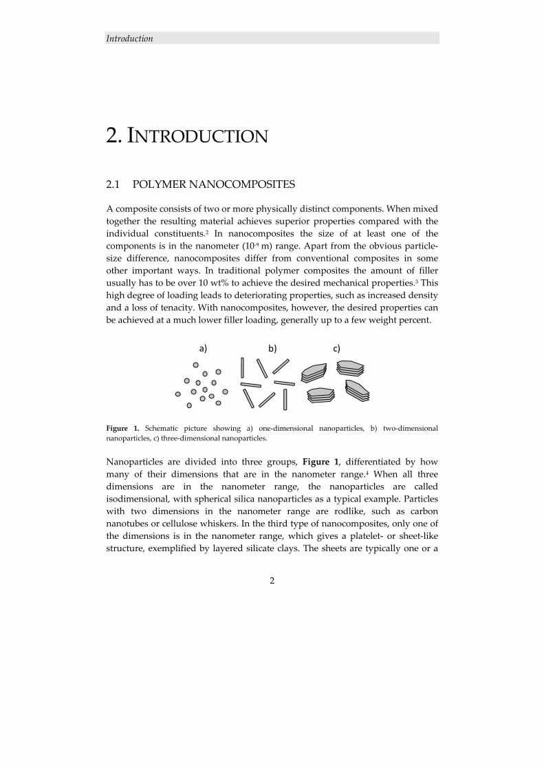
Figure 1. Schematic picture showing a) one‐dimensional nanoparticles, b) two‐dimensional nanoparticles, c) three‐dimensional nanoparticles. Nanoparticles are divided into three groups, Figure 1, differentiated by how many of their dimensions that are in the nanometer range.4 When all three dimensions are in the nanometer range, the nanoparticles are called isodimensional, with spherical silica nanoparticles as a typical example. Particles with two dimensions in the nanometer range are rodlike, such as carbon nanotubes or cellulose whiskers. In the third type of nanocomposites, only one of the dimensions is in the nanometer range, which gives a platelet‐ or sheet‐like structure, exemplified by layered silicate clays. The sheets are typically one or a
a) b) c)
Introduction
3
few nanometers thick with a surface of several thousand square nanometers, which gives a very high aspect ratio.
2.2 POLYMER/CLAY NANOCOMPOSITES
The great interest in using clay nanoparticles as reinforcement in polymers emerged in the late 1980s when a research group from Toyota reported their findings regarding the possibility of building a nanostructure from a polymer and an organophilic clay, with dramatic property improvements.5, 6
2.2.1 Montmorillonite clay
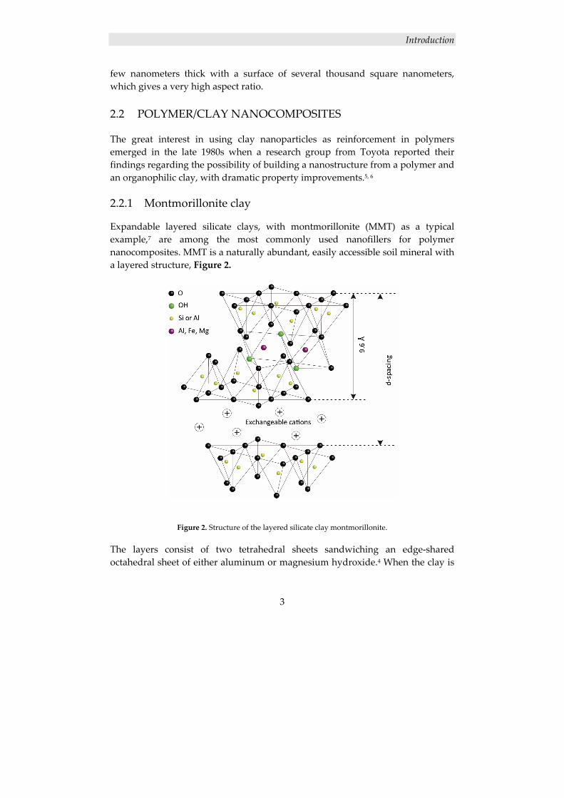
Expandable layered silicate clays, with montmorillonite (MMT) as a typical example,7 are among the most commonly used nanofillers for polymer nanocomposites. MMT is a naturally abundant, easily accessible soil mineral with a layered structure, Figure 2.
Figure 2. Structure of the layered silicate clay montmorillonite.
The layers consist of two tetrahedral sheets sandwiching an edge‐shared octahedral sheet of either aluminum or magnesium hydroxide.4 When the clay is
Introduction
4
stacked, each layer is separated by regular van der Waals gaps, called interlayers or galleries. Located in the interlayers are cations such as Ca2+ and Na+, counterbalancing an excess of negative charge, caused by isomorphous substitutions of Si4+ for Al3+ within the tetrahedral lattice, and of Al3+ for Mg2+ in the octahedral lattice. There are also often water molecules present between the layers, due to the high hydrophilicity of the clay. The repeating unit, d‐spacing, is represented by the sum of the single layer thickness and the interlayer. In natural MMT (Na+MMT), the d‐spacing varies from 9.6 Å, for the stacked dry clay, to 19 Å for the clay in 99% relative humidity.8 The microstructure of the clay consists of several layers, lamellas (1 nm), lying parallel forming a primary particle (8‐10 nm). The primary particles are, in turn, aggregated into larger irregular particles (0.1‐10 μm).9 The layered structure together with the suitable layer charge density enable a rich intercalating chemistry, thus allowing for MMT to be intercalated directly with hydrophilic polymers or chemically modified to enhance the compatibility with hydrophobic polymers.10
2.2.2 Structure of polymer/clay nanocomposites
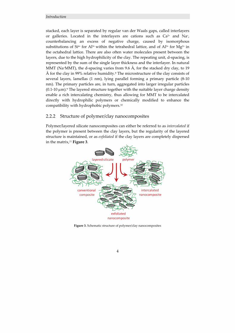
Polymer/layered silicate nanocomposites can either be referred to as intercalated if the polymer is present between the clay layers, but the regularity of the layered structure is maintained, or as exfoliated if the clay layers are completely dispersed in the matrix,11 Figure 3.
Figure 3. Schematic structure of polymer/clay nanocomposites
layered silicate polymer
conventional composite
intercalated nanocomposite
exfoliated nanocomposite
Introduction
5
In order to fully utilize the property‐improving potential of the nanofiller, complete dispersion is necessary, so that the entire surface area (ca 760 m2/g) of the nanosized clay particles is available to interact with the polymer; the coupling between the phases facilitates stress transfer to the reinforcing phase, allowing for tensile strength and toughening improvements.10
2.2.3 Preparation of polymer/clay nanocomposites
Various methods have been employed to prepare polymer/clay nanocomposites. The first method, used by the Toyota group, was the in‐situ synthesis.12‐16 In this method, the polymerization is initiated in between the clay layers, and the polymer build‐up causes the interlayer gallery to expand. Another commonly used method is the melt processing technique, in which the clay is dispersed in a polymer in the molten state, using high shear forces and high temperatures.17‐20 In the solution intercalation method the layered silicate is exfoliated into single layers using a solvent in which the polymer is soluble.4 The weak forces stacking the layers together make the dispersion of the inorganic material easy, if the solvent is adequate. Subsequently, the polymer adsorbs onto the delaminated sheets and the nanocomposite is formed upon removal of the solvent. The above described nanocomposite preparation methods generally require modification of the naturally hydrophilic clay to improve the compatibility with commonly used hydrophobic polymers. Depending on the desired properties, several modifying methods are applicable. The simplest method is the reaction with alkylammonium ions, due to the ease with which the alkyl chains can change their conformation by transition into kink and gauche conformers.21 In addition, many different properties can be obtained depending on the choice of carbon chain in the alkylammonium ion. Therefore, this type of modifier has shown to be particularly versatile in polymer/clay nanocomposites.22, 23 The purpose of the alkylammonium ion is not just to compatibilize the clay and the polymer but it also expands the clay galleries, making intercalation easier.10 However, modification of the clay could be avoided using the solution intercalation method with water as solvent, thereby making use of native MMT’s affinity for water and its ability to exfoliate in aqueous solutions.24, 25
2.2.4 Characterization of polymer/clay nanocomposites
There are two main methods in the characterization of polymer/clay nanocomposites:7, 26 x‐ray diffraction (XRD) and transmission electron microscopy (TEM). XRD is a straightforward method for determining the spacing between the clay layers; the sample preparation is relatively easy and the analysis can be
Introduction
6
performed within a few hours. The potential of XRD, however, is limited since all its data is averaged over the whole sample. Furthermore, XRD does not give any information concerning the spatial distribution of the clay particles. These limitations may lead to incorrect conclusions regarding the nanocomposite structure, and need to be taken into careful consideration when interpreting the results. TEM is thus an important complement to XRD. TEM provides direct visual information of the morphology, atom arrangement, spatial distribution of the phases and structural defects of an elected area of the sample. In this method, the limitations are rather operational than instrumental, since TEM requires substantial skills in specimen preparation and analysis in order to ensure that a representative section is examined.
2.2.5 Properties of polymer/clay nanocomposites
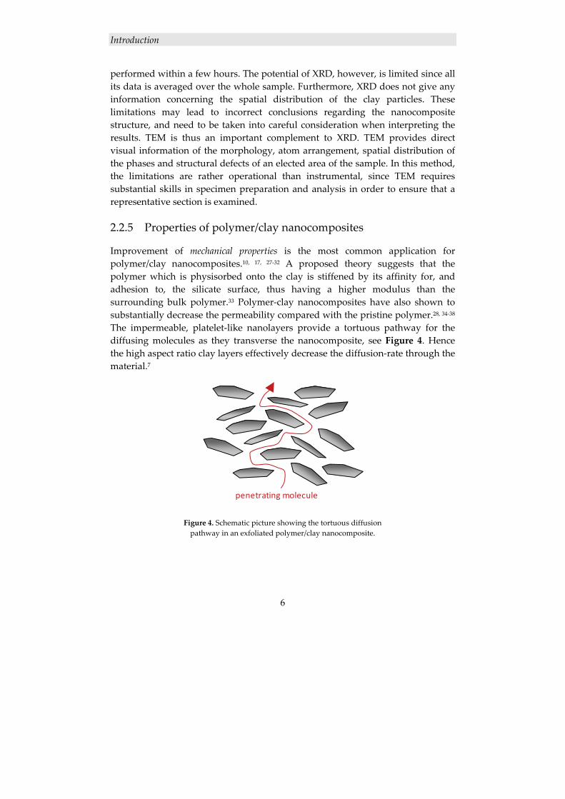
Improvement of mechanical properties is the most common application for polymer/clay nanocomposites.10, 17, 27‐32 A proposed theory suggests that the polymer which is physisorbed onto the clay is stiffened by its affinity for, and adhesion to, the silicate surface, thus having a higher modulus than the surrounding bulk polymer.33 Polymer‐clay nanocomposites have also shown to substantially decrease the permeability compared with the pristine polymer.28, 34‐38 The impermeable, platelet‐like nanolayers provide a tortuous pathway for the diffusing molecules as they transverse the nanocomposite, see Figure 4. Hence the high aspect ratio clay layers effectively decrease the diffusion‐rate through the material.7
Figure 4. Schematic picture showing the tortuous diffusion pathway in an exfoliated polymer/clay nanocomposite.
penetrating molecule
Introduction
7
Closely related to the improvement of barrier properties is the improvement of thermal properties, benefitted by in thermal‐stability and fire‐resistance applications.4, 39‐44 The thermal stability is improved since the clay layers act as superior insulator and mass transport barrier to the volatile products generated during decomposition, as well as by assisting the char formation after thermal decomposition, especially on the outer layer.33 The clay‐rich char layer in turn protects the polymer from hot flames during fire and slows the oxygen uptake and the escape of volatile gases produced by the polymer degradation. Important for many applications,12, 45, 46 for example coating applications,47 are the optical properties of nanocomposites. The nanometric dimension of the filler is smaller than the wavelength of visible light, i.e., the light is not refracted, thus rendering the nanocomposites highly transparent.48 Furthermore, the introduction of nanoparticles to crystalline materials affects the crystallinity, in turn affecting the optical clarity.49 The transparency of nanocomposites makes them applicable outside the boundaries of traditional composites.
2.3 DENDRITIC POLYMERS
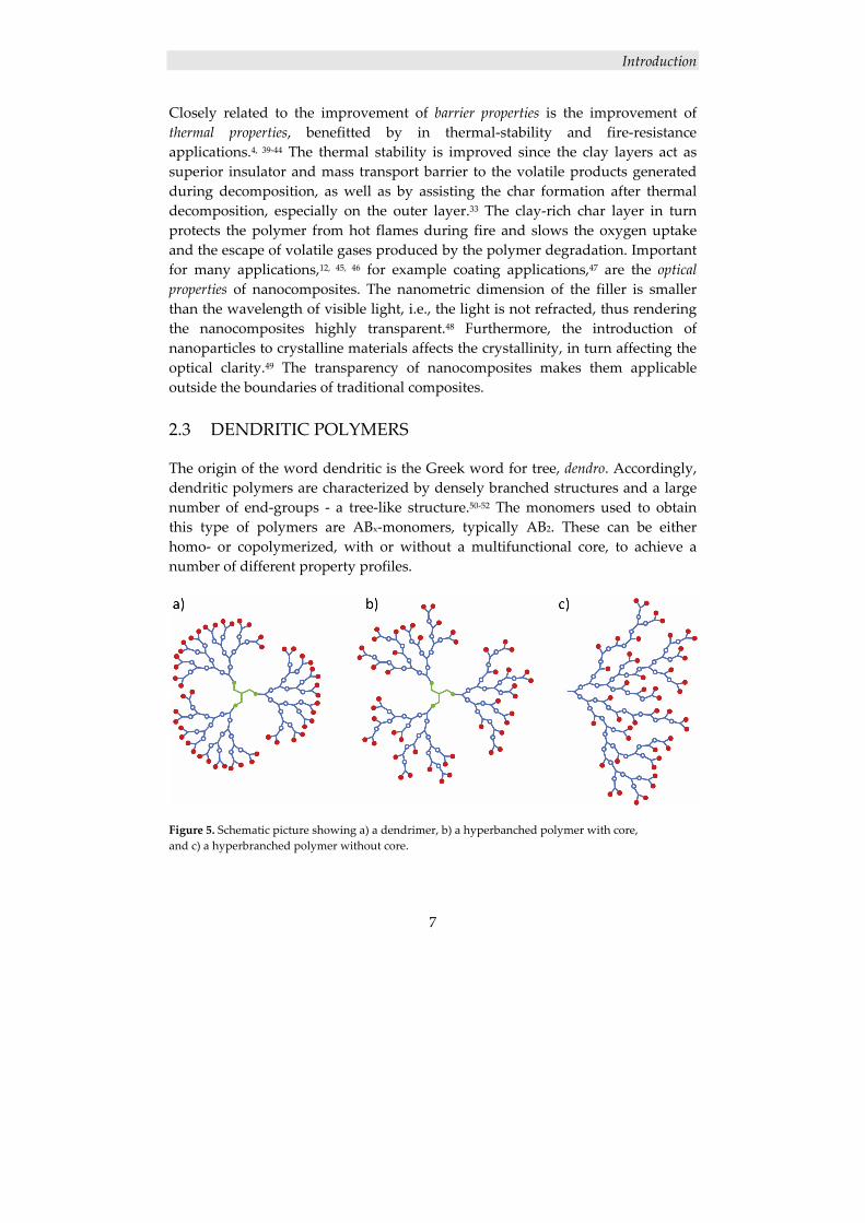
The origin of the word dendritic is the Greek word for tree, dendro. Accordingly, dendritic polymers are characterized by densely branched structures and a large number of end‐groups ‐ a tree‐like structure.50‐52 The monomers used to obtain this type of polymers are ABx‐monomers, typically AB2. These can be either homo‐ or copolymerized, with or without a multifunctional core, to achieve a number of different property profiles.
Figure 5. Schematic picture showing a) a dendrimer, b) a hyperbanched polymer with core, and c) a hyperbranched polymer without core.
Introduction
8
If a core is used and the product is monodisperse ‐ a dendrimer ‐ each layer of propagation is represented by a generation, Figure 5a, and if the product is polydisperse ‐ a hyperbranched polymer ‐ the term pseudo‐generation is used, Figure 5b. If no core is used in the synthesis, the product is a hyperbranched polymer with a theoretical infinitely broad molecular‐weight distribution,50 Figure 5c. Also belonging to the family of dendritic polymers are linear‐dendritic‐hybrid polymers, such as dendrigrafts and dendronized polymers.52
2.3.1 Hyperbranched polymers
Hyperbranched macromolecules, theoretically described in the 1950’s,53 were first reported synthesized in the early 1990’s54 and have been studied in detail since then.55, 56 The synthesis of dendrimers,57‐60 is often tedious since it generally requires protection and deprotection steps as well as purification between successive generations. Hyperbranched polymers on the other hand, are readily synthesized through a one‐pot61 or pseudo‐one‐pot62 synthesis. One‐pot‐synthesis, with or without a core, is performed by adding all ABx monomers simultaneously, resulting in an uncontrolled branching and a very broad molecular‐weight distribution, typically 2 or higher.52 In the pseudo‐one‐pot synthesis a core is used, and the ABx monomers are added in a stoichiometric ratio, one pseudo‐generation at a time,62 enabling a better controlled polymerization with a higher degree of branching and a more narrow molecular‐weight distribution. While having the same amount of end‐groups, the main distinguishing properties for hyperbranched polymers compared with dendrimers, are higher molecular weight distribution and irregular branching. These, in some cases undesired, properties are a result of the one‐pot, or pseudo‐one‐pot synthesis, applied on hyperbranched polymers. However, the simple synthesis renders the preparation of hyperbranched polymer less expensive,50 which is a highly desired feature, facilitating commercial applications.61, 63‐65
2.3.1.1 Properties of hyperbranched polymers
The structure of hyperbranched polymers, densely branched with a large number of end‐groups, differs from the structure of linear or conventionally branched polymers; hence, the properties differ as well. The globular structure of hyperbranched polymers precludes the entanglements that conventional polymers undergo, which leads to lower viscosity at a given molecular weight.66 Also, the hyperbranched polymer exhibits a Newtonian behavior, which is unusual for polymers.67 As can be anticipated from their highly branched architecture, hyperbranched polymers are most often amorphous; however, some
Introduction
9
exceptions are reported in the literature.68, 69 The large number of end‐groups has a great effect on the properties of the hyperbranched polymer since they strongly affect the interactions between the hyperbranched polymer and its neighboring molecules, thus affecting the solubility and viscosity. Furthermore, the nature of the end‐groups governs the reactivity of the molecule. Due to the large number of end‐groups, hyperbranched polymers have a great capacity for rapid crosslinking even at moderate molecular weights, if the end‐groups are reactive. Hence, the possibilities for designing thermosetting networks are numerous.56
2.3.1.2 Derivatization of hyperbranched polymers
The large number of end‐groups of hyperbranched polymers strongly governs the final unique properties of the material, as mentioned above. Often only a small amount of end‐groups has to be derivatized to achieve, for instance, a desired reactivity and therefore the rest can be used to control other properties, such as viscosity, solubility etc. For example, acrylate and methacrylate derivatives of hyperbranched polymers can be synthesized using standard procedures, resulting in UV‐curable systems.70, 71
2.3.1.3 Boltorn®
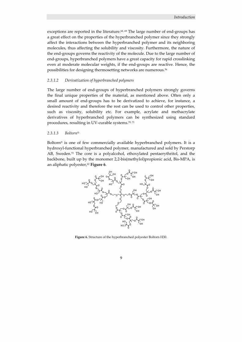
Boltorn® is one of few commercially available hyperbranched polymers. It is a hydroxyl‐functional hyperbranched polymer, manufactured and sold by Perstorp AB, Sweden.72 The core is a polyalcohol, ethoxylated pentaerythritol, and the backbone, built up by the monomer 2,2‐bis(methylol)propionic acid, Bis‐MPA, is an aliphatic polyester,62 Figure 6.
Figure 6. Structure of the hyperbranched polyester Boltorn H30.
Introduction
10
Since Boltorn® is produced through a pseudo‐one‐pot synthesis, offering some degree of control over the polymerization, the polydispersity is fairly low, with a PDI value ranging from 1.4 to 2.4, as reported in the literature.62, 72, 73 The use of a core also allows for some control over the molecular weight. The Boltorn® used in this thesis is Boltorn H30, which is a hyperbranched polymer of the third pseudo‐generation, having a molecular weight (Mn) of about 3600 g/mol and an average of 32 hydroxyl end‐groups per molecule.
2.4 DENDRITIC POLYMER/CLAY NANOCOMPOSITES
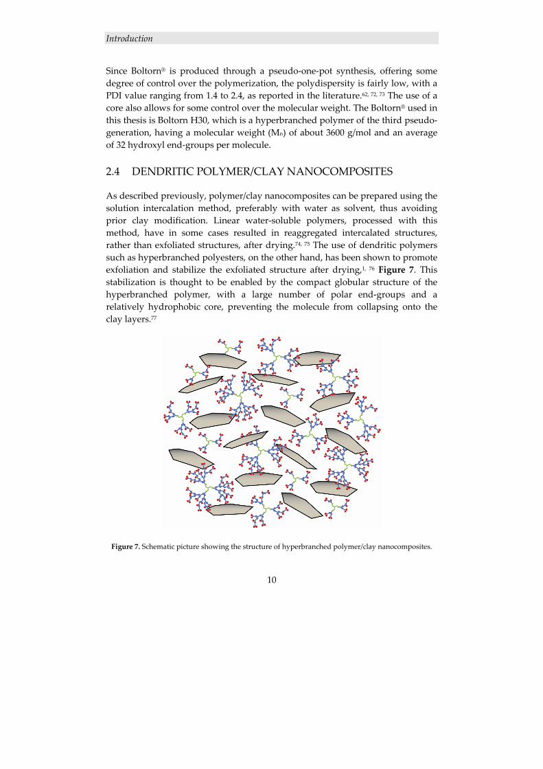
As described previously, polymer/clay nanocomposites can be prepared using the solution intercalation method, preferably with water as solvent, thus avoiding prior clay modification. Linear water‐soluble polymers, processed with this method, have in some cases resulted in reaggregated intercalated structures, rather than exfoliated structures, after drying.74, 75 The use of dendritic polymers such as hyperbranched polyesters, on the other hand, has been shown to promote exfoliation and stabilize the exfoliated structure after drying,1, 76 Figure 7. This stabilization is thought to be enabled by the compact globular structure of the hyperbranched polymer, with a large number of polar end‐groups and a relatively hydrophobic core, preventing the molecule from collapsing onto the clay layers.77
Figure 7. Schematic picture showing the structure of hyperbranched polymer/clay nanocomposites.
Introduction
11
2.5 CELLULOSE
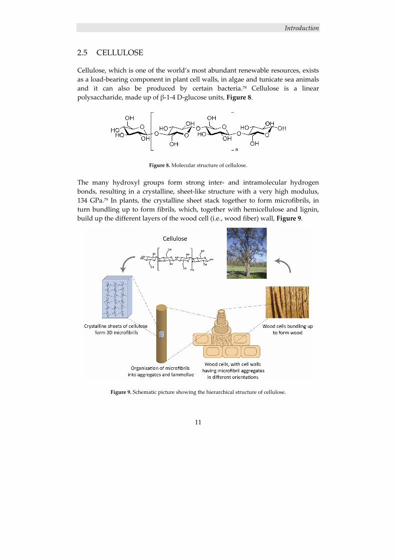
Cellulose, which is one of the world’s most abundant renewable resources, exists as a load‐bearing component in plant cell walls, in algae and tunicate sea animals and it can also be produced by certain bacteria.78 Cellulose is a linear polysaccharide, made up of β‐1‐4 D‐glucose units, Figure 8.
Figure 8. Molecular structure of cellulose.
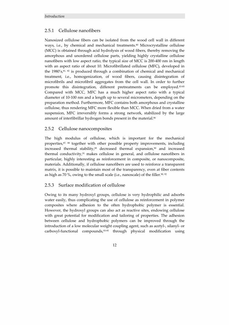
The many hydroxyl groups form strong inter‐ and intramolecular hydrogen bonds, resulting in a crystalline, sheet‐like structure with a very high modulus, 134 GPa.79 In plants, the crystalline sheet stack together to form microfibrils, in turn bundling up to form fibrils, which, together with hemicellulose and lignin, build up the different layers of the wood cell (i.e., wood fiber) wall, Figure 9.
Figure 9. Schematic picture showing the hierarchical structure of cellulose.
Introduction
12
2.5.1 Cellulose nanofibers
Nanosized cellulose fibers can be isolated from the wood cell wall in different ways, i.e., by chemical and mechanical treatments.80 Microcrystalline cellulose (MCC) is obtained through acid hydrolysis of wood fibers, thereby removing the amorphous and unordered cellulose parts, yielding highly crystalline cellulose nanofibers with low aspect ratio; the typical size of MCC is 200‐400 nm in length with an aspect ratio of about 10. Microfibrillated cellulose (MFC), developed in the 1980’s,81, 82 is produced through a combination of chemical and mechanical treatment, i.e., homogenization, of wood fibers, causing disintegration of microfibrils and microfibril aggregates from the cell wall. In order to further promote this disintegration, different pretreatments can be employed.83‐85 Compared with MCC, MFC has a much higher aspect ratio with a typical diameter of 10‐100 nm and a length up to several micrometers, depending on the preparation method. Furthermore, MFC contains both amorphous and crystalline cellulose, thus rendering MFC more flexible than MCC. When dried from a water suspension, MFC irreversibly forms a strong network, stabilized by the large amount of interfibrillar hydrogen bonds present in the material.86
2.5.2 Cellulose nanocomposites
The high modulus of cellulose, which is important for the mechanical properties,87, 88 together with other possible property improvements, including increased thermal stability,89 decreased thermal expansion,90 and increased thermal conductivity,91 makes cellulose in general, and cellulose nanofibers in particular, highly interesting as reinforcement in composite, or nanocomposite, materials. Additionally, if cellulose nanofibers are used to reinforce a transparent matrix, it is possible to maintain most of the transparency, even at fiber contents as high as 70 %, owing to the small scale (i.e., nanoscale) of the filler.90, 92
2.5.3 Surface modification of cellulose
Owing to its many hydroxyl groups, cellulose is very hydrophilic and adsorbs water easily, thus complicating the use of cellulose as reinforcement in polymer composites where adhesion to the often hydrophobic polymer is essential. However, the hydroxyl groups can also act as reactive sites, endowing cellulose with great potential for modification and tailoring of properties. The adhesion between cellulose and hydrophobic polymers can be improved through the introduction of a low molecular weight coupling agent, such as acetyl‐, silanyl‐ or carboxyl‐functional compounds,93‐95 through physical modification using
Introduction
13
secondary forces,84, 96 or through graft‐copolymerization of high molecular weight polymers, thereby making use of the possibility of obtaining chain entanglements that drastically improve the mechanical properties, as well as the possibility for co‐crystallization to occur with the polymer matrix. Co‐crystallization would further improve the interfacial adhesion between matrix and fiber, and thereby enhance the mechanical properties of the final composite. The surface grafting from cellulose has traditionally been performed through radiation‐initiated free radical polymerization of vinyl monomers, resulting in high molecular weight grafts with poor definition.97, 98 Surface modification of cellulose using controlled polymerization techniques, such as ATRP,99‐101 RAFT,102‐104 and ROP,105‐107 on the other hand, offer the possibility of obtaining surface‐confined polymers with controlled molecular weight and molecular weight distribution and chain structure, i.e., block copolymers, graft‐on‐graft copolymers etc.
2.6 CONTROLLED POLYMERIZATION
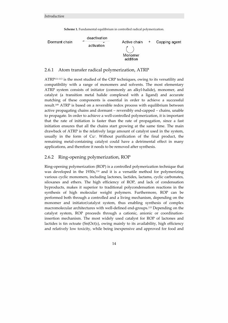
In order to control the molecular weight, the molecular weight distribution and the end‐group functionality of a polymer, the synthesis has to be performed using a living or controlled polymerization technique. Anionic and cationic polymerization are true living techniques, offering complete control over the polymerization. However, they are synthetically demanding in their requirement of ultrapure reactants and specific reaction conditions, thus limiting their commercial use. The most commonly used method for commercial applications is free radical polymerization, but since it lacks control over the polymerization regarding termination and chain transfer reactions, molecular weight and molecular weight distribution, and end‐group functionality, it cannot be used to synthesize well‐defined polymers, such as star, comb or block copolymers, requiring architectural control. In the effort to combine the control of the living polymerization techniques with the less‐demanding synthesis of the free radical polymerization, controlled radical polymerization (CRP) techniques have been developed; the three major types are nitroxide mediated polymerization (NMP),108 atom transfer radical polymerization (ATRP),109 and reversible addition fragmentation chain transfer polymerization (RAFT)110. By maintaining a low concentration of active propagating species, through a dynamic equilibrium as shown in Scheme 1, termination and unwanted side‐reactions are suppressed, thus offering control over the polymerization and the end‐group functionality.
Introduction
14
Scheme 1. Fundamental equilibrium in controlled radical polymerization.
2.6.1 Atom transfer radical polymerization, ATRP
ATRP111‐113 is the most studied of the CRP techniques, owing to its versatility and compatibility with a range of monomers and solvents. The most elementary ATRP system consists of initiator (commonly an alkyl‐halide), monomer, and catalyst (a transition metal halide complexed with a ligand) and accurate matching of these components is essential in order to achieve a successful result.109 ATRP is based on a reversible redox process with equilibrium between active propagating chains and dormant – reversibly end‐capped – chains, unable to propagate. In order to achieve a well‐controlled polymerization, it is important that the rate of initiation is faster than the rate of propagation, since a fast initiation ensures that all the chains start growing at the same time. The main drawback of ATRP is the relatively large amount of catalyst used in the system, usually in the form of Cu+. Without purification of the final product, the remaining metal‐containing catalyst could have a detrimental effect in many applications, and therefore it needs to be removed after synthesis.
2.6.2 Ring‐opening polymerization, ROP
Ring‐opening polymerization (ROP) is a controlled polymerization technique that was developed in the 1930s,114 and it is a versatile method for polymerizing various cyclic monomers, including lactones, lactides, lactams, cyclic carbonates, siloxanes and ethers. The high efficiency of ROP, and lack of condensation byproducts, makes it superior to traditional polycondensation reactions in the synthesis of high molecular weight polymers. Furthermore, ROP can be performed both through a controlled and a living mechanism, depending on the monomer and initiator/catalyst system, thus enabling synthesis of complex macromolecular architectures with well‐defined end‐groups.115 Depending on the catalyst system, ROP proceeds through a cationic, anionic or coordination‐insertion mechanism. The most widely used catalyst for ROP of lactones and lactides is tin octoate (Sn(Oct)2), owing mainly to its availability, high efficiency and relatively low toxicity, while being inexpensive and approved for food and
Introduction
15
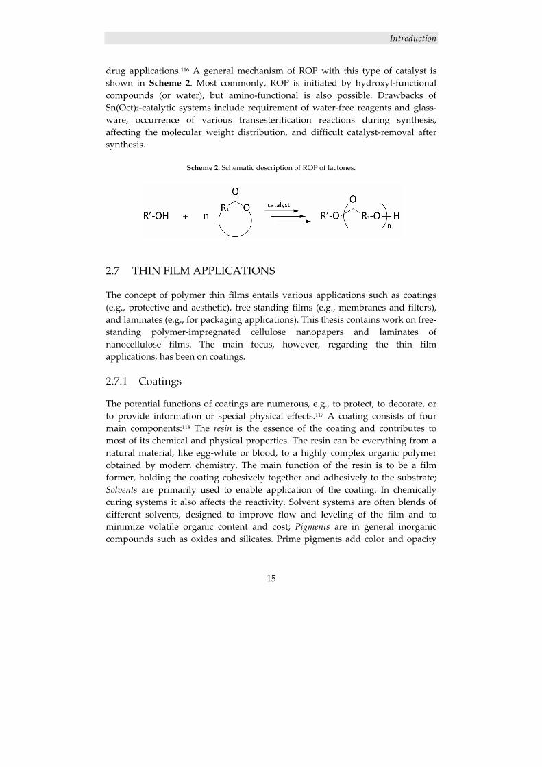
drug applications.116 A general mechanism of ROP with this type of catalyst is shown in Scheme 2. Most commonly, ROP is initiated by hydroxyl‐functional compounds (or water), but amino‐functional is also possible. Drawbacks of Sn(Oct)2‐catalytic systems include requirement of water‐free reagents and glass‐ware, occurrence of various transesterification reactions during synthesis, affecting the molecular weight distribution, and difficult catalyst‐removal after synthesis.
Scheme 2. Schematic description of ROP of lactones.
2.7 THIN FILM APPLICATIONS
The concept of polymer thin films entails various applications such as coatings (e.g., protective and aesthetic), free‐standing films (e.g., membranes and filters), and laminates (e.g., for packaging applications). This thesis contains work on free‐standing polymer‐impregnated cellulose nanopapers and laminates of nanocellulose films. The main focus, however, regarding the thin film applications, has been on coatings.
2.7.1 Coatings
The potential functions of coatings are numerous, e.g., to protect, to decorate, or to provide information or special physical effects.117 A coating consists of four main components:118 The resin is the essence of the coating and contributes to most of its chemical and physical properties. The resin can be everything from a natural material, like egg‐white or blood, to a highly complex organic polymer obtained by modern chemistry. The main function of the resin is to be a film former, holding the coating cohesively together and adhesively to the substrate; Solvents are primarily used to enable application of the coating. In chemically curing systems it also affects the reactivity. Solvent systems are often blends of different solvents, designed to improve flow and leveling of the film and to minimize volatile organic content and cost; Pigments are in general inorganic compounds such as oxides and silicates. Prime pigments add color and opacity
Introduction
16
and they can protect the coating from deteriorating UV‐light. Functional pigments can provide for example fire resistance or corrosion protection. Extender pigments increases volume without excessive cost. They add neither color nor opacity, but they can for instance provide mechanical strength and control gloss; In the coating industry numerous additives are used to improve various properties. Plasticizers can provide flexibility to brittle polymers, catalysts and driers can accelerate cure rates, etc. An important group of additives are the rheological additives, used to control consistency and pigment settling and improve flow, leveling and sag resistance of the film.
2.7.1.1 Coating types
There are four main classifications of coatings, categorized by the resin and how the coating is formed:118, 119 The simplest type of coating is the thermoplastic solvent‐borne resins, in which a continuous film is formed when the solvent is evaporated and an amorphous solid is obtained. No cross‐linking occurs, but usually considerable physical entanglements are formed. Examples of this type are acrylics, vinyls, chlorinated rubbers, and cellulosic esters; In the thermoplastic dispersion resins, a high molecular weight polymer is segregated into discrete particles dispersed in a carrier phase. A continuous film is formed after application when the carrier phase is evaporated or displaced and the polymer particles are fused together. The dispersion enables a low viscosity despite the high molecular weight. Examples of this type are latex systems, plastisols, and thermoplastic powder coating resins; The chemically curing resins are crosslinked by intra‐ or intermolecular addition or condensation polymerization. The curing can proceed at either ambient or elevated temperature, with ultra‐violet (UV) or electron‐beam (EB) radiation, depending on the functional groups involved. Examples of this type are epoxy systems, urethane systems, unsaturated polyesters, UV and EB curing acrylics, phenolics and amino cured systems; A very old film forming technology, still in use, is the oxidatively curing system, with a crosslinking chemistry yet to be fully understood. The oxidizing systems, however, involve an oxygen attack on conjugated double bonds on unsaturated fatty acids. This attack creates radicals ready to react with other fatty acid chains, and so the drying process proceeds. Examples of this type are oxidizing systems like unmodified oil systems, alkyds and epoxy esters, and water curing systems like ureas and alkyl silicates.
Introduction
17
2.7.1.2 Rheology of coatings
A very important property of coatings is the viscosity; a sufficiently low viscosity is required in order to control the flow and leveling during film formation.120, 121 When designing a coating system there generally has to be a compromise between molecular weight and viscosity. While being essential in order obtain the right properties of the final film and to reduce cure shrinkage, a high molecular weight of the resin normally also renders a high viscosity. In order to lower the viscosity, an increased amount of solvent is required, which is undesirable also from an environmental point of view. Dendritic polymers, with their special features, offer an interesting alternative in the solution to this problem.
2.7.1.3 Dendritic polymers in coatings
One of the most prominent applications for dendritic polymers is as reactive multifunctional components in coating and resin formulations.56, 122 As discussed in section 2.3.1.1, the globular structure of hyperbranched polymers precludes the entanglement that conventional polymers undergo, which leads to lower viscosity at a given molecular weight and a Newtonian behavior. Additionally, the large number of end‐groups renders versatile cross‐linking possibilities and a great capacity for rapid curing.
2.7.1.4 Nanocomposite coatings
Many of the properties of nanocomposites described in section 2.2.5 are very useful in coating applications: improvements in mechanical properties would render a harder and more scratch resistant coating;47 the increased thermal stability and fire resistant properties are applicable in intumescent coatings123 and other fire retardant applications; the improved barrier properties are also pertinent, e.g., to packaging applications; the possibility of maintaining the transparency of a nanoparticle‐filled coating enables their use as clear‐coats, e.g., in wood or automotive applications.
Experimental
18
3. EXPERIMENTAL
3.1 MATERIALS
The hydroxyl‐functional hyperbranched polymer Boltorn® H30 and 2,2‐bis(methylol)propionic acid (Bis‐MPA) was kindly supplied by Perstorp AB Sweden. The clay used is a natural montmorillonite (Na+MMT) from the Cloisite® nanoclays series by Southern Clay Products, with a d‐spacing of 11.7 Å according to SCP’s X‐ray results. Hexamethoxymethyl melamine (HMMM) was supplied by Becker Industrial Coatings AB, and epoxy‐blocked p‐toluenesulfonic acid (epoxy‐blocked pTSA) was supplied by Akzo Nobel Nippon Paint AB. Microfibrillated cellulose (MFC) was prepared according to the procedure described by Henriksson et al.85. Glycidyl methacrylate (GMA) from Fluka was passed through a column of neutral aluminum oxide from Sigma‐Aldrich prior to use. All solvents and the following chemicals were used as received: TONE polyol 0301 from Union Carbide, 2,2,4‐trimethyl‐1,3‐pentanediol monoisobutyrate (Texanol), benzyl alcohol, 2‐bromoisobutyrate (EBiB), ε‐caprolactone (ε‐CL), poly(ε‐caprolactone) (PCL, MW 80 000 g/mol), copper(I)chloride (Cu(I)Cl), copper(II)bromide (Cu(II)Br2) hydroquinone, pentamethyldiethyltriamine (PMDETA) and tin octoate (Sn(Oct2)) from Sigma‐Aldrich, acrylic acid and methanesulfonic acid from Merck, nitrobenzene from Kebo Lab, tripropyleneglycol diacrylate (TPGDA) from UCB Radcure, Irgacure 651 from Ciba Specialty Chemicals, hydrochloric acid (HCl, 37 % solution in water) from Acros Organics, and tetrabutyl ammonium bromide (TBAB) from Nobel Chemicals.
3.2 CHARACTERIZATION METHODS
Atomic force microscopy (AFM) was performed using a Nanoscope III‐a system (Digital Instruments) equipped with an EV‐type vertically engaged piezoelectric scanner operating in tapping mode in air. Silicon AFM probes from Veeco (Nanosensors) were used with a resonance frequency of 275‐348 kHz.
Experimental
19
Conventional coating characterization methods: pendulum hardness was studied with a 299 Koenig pendulum hardness tester from Erichsen; pencil hardness tests were principally performed according to SIS 18 41 87 standard, using pencils manufactured by KOH‐I‐NOOR; scratch tests were principally performed according to ISO 2409 standard, using a multi‐edge cutting tool and a brush, both manufactured by Erichsen; chemical resistance was analyzed through the MEK‐rub test, using methyl ethyl ketone as solvent. Density and porosity of the matrix and the cellulose nanofiber film in Paper IV was determined using an Archimedes scale. The density was calculated from sample displacement when immersed in mercury and the porosity was calculated assuming a cellulose density of 1500 kg/m3. Dynamic mechanical analysis (DMA) was performed on freestanding films using a TA Instruments Q800 to determine the tensile properties of the coatings in Paper II and the films in Paper IV. The peel tests in Paper VI were also conducted with the DMA instrument. These measurements were performed on rectangular laminate samples (20x4 mm) at room temperature in a controlled stress‐strain mode with a preload force of 0.0010 N and a force ramp of 0.100 N/min. Field emission scanning electron mircroscopy (FE‐SEM) was performed using a Hitachi S‐4800 scanning electron microscope. The specimens were coated by gold using an Agar HR sputter coater. The surfaces of the composites and the fracture surfaces were analyzed at 2 kV acceleration voltage. Fourier transform infrared spectroscopy (FTIR) was conducted on a Perkin‐Elmer Spectrum 2000 FTIR equipped with a MKII Golden Gate, Single Reflection ATR system from Specac Ltd., London, UK. All spectra were normalized against a specific ATR crystal adsorption, thus enabling comparison between the polymer grafted cellulose substrates.99 Nuclear magnetic resonance (1H‐NMR and 13C‐NMR) spectra were recorded on a 400 MHz Bruker Aspect NMR, using DMSO‐d6 and CDCl3 as solvents. Size exclusion chromatography (SEC), using THF (1.0 mL min‐1) as the mobile phase was performed at 35 °C using a Viscotek TDA model 301 equipped with two GMHHR‐M columns with TSK‐gel (Tosoh Biosep), a VE 5200 GPC autosampler, a VE 1121 GPC solvent pump, and a VE 5710 GPC degasser (all from Viscotek
Experimental
20
corporation). A calibration method was created using narrow linear polystyrenes standards. Corrections for the flow rate fluctuations were made using toluene as an internal standard. Static contact angle (CA) measurements were conducted on a KSV instruments CAM 200 equipped with a Basler A602f camera, using 5 μL droplets of MilliQ water and a relative humidity of 50%. The contact angles were determined using the CAM software. Tensile tests of the films in Paper IV were performed with a Universal Materials Testing Machine from Instron, equipped with a 100 N or a 500 N load cell. Specimens were 5 mm wide and thicknesses were uniform and 50 ‐ 230 μm depending on composition. Grip distance was 20 mm and testing was performed at a cross‐head speed of 2 mm/min. Specimens were conditioned and tested at 50% relative humidity and 23 °C. Displacement was measured by differential speckle photography (DSP). A pattern was prepared for the DSP by printer toner. The toughness is defined as work‐to‐fracture calculated from the area under the stress‐strain curve. Thermogravimetric analysis (TGA) was performed on a Mettler Toledo TGA/SDTA851e instrument. The samples in Paper I were heated from 40 °C to 800 °C with a heating rate of 10 °C/min, and a N2 or O2 flow of 50 mL/min. The samples in Paper V were heated from 30 °C to 600 °C with a heating rate of 10 °C/min, and a N2 flow of 80 mL/min. Transmission electron microscopy (TEM) analysis was performed on a Philips Tecnai 10, using an acceleration voltage of 80 kV. The TEM samples were prepared from cured coatings, cast in epoxy and cut with an ultramicrotome. UV‐curing of the coatings was performed with a Fusion System UV‐oven, equipped with an H‐bulb. The intensity of the UV‐light was 0.1 J/cm2, measured in the wavelength interval 320–390 nm. X‐ray diffraction (XRD) analysis in Paper I was performed with a single crystal diffractometer STOE IPDS in transmission mode, using molybdenum radiation MoKα (λ≈0.71073 Å), and in Paper II with a PANalytical XPert Pro powder diffractometer in reflection mode, using copper radiation, CuKα1 (λ≈1.5406 Å).
Experimental
21
3.3 EXPERIMENTAL PROCEDURES
The following section briefly describes the performed experimental procedures. Full detail can be found in the appended papers.
3.3.1 Boltorn H30/Na+MMT nanocomposite coatings
3.3.1.1 Preparation of Boltorn H30/Na+MMT nanocomposites (Paper I and II)
Prior to the reaction, Boltorn H30 was preheated until it appeared molten in order to break the hydrogen bonds spontaneously forming in the material upon storage.124‐126 Then the Boltorn H30 was dissolved in boiling deionized water until a cloudy solution was obtained. Na+MMT, pre‐dispersed in boiling deionized water, was added under vigorous stirring. After 1 h the temperature was reset to 50 °C, the stopper removed, and the mixture kept under maintained stirring until half the amount of water had evaporated. The resulting “gel” was dried in air at 50 °C for 2‐4 days and under vacuum at 50 °C for another 2‐4 days until the rest of the water was removed, and a solid was obtained.
3.3.1.2 Preparation of thermally cured coatings (Paper II)
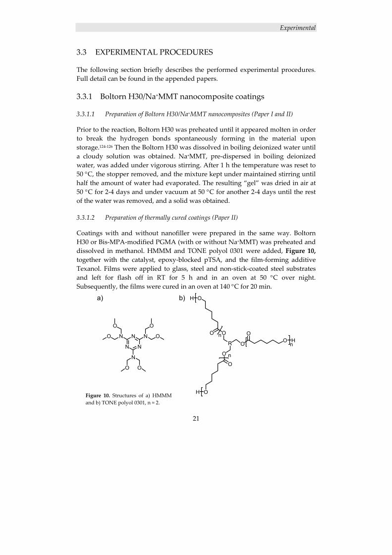
Coatings with and without nanofiller were prepared in the same way. Boltorn H30 or Bis‐MPA‐modified PGMA (with or without Na+MMT) was preheated and dissolved in methanol. HMMM and TONE polyol 0301 were added, Figure 10, together with the catalyst, epoxy‐blocked pTSA, and the film‐forming additive Texanol. Films were applied to glass, steel and non‐stick‐coated steel substrates and left for flash off in RT for 5 h and in an oven at 50 °C over night. Subsequently, the films were cured in an oven at 140 °C for 20 min.
N N
NN N
N
O
O
O
O
OO
O
OO H
O
O
OH
OO
OH
Rn
n
n
a) b)
Figure 10. Structures of a) HMMM and b) TONE polyol 0301, n ≈ 2.
Experimental
22
3.3.2 Acrylated Boltorn H30/Na+MMT nanocomposite coatings
3.3.2.1 Synthesis of acrylated Boltorn H30
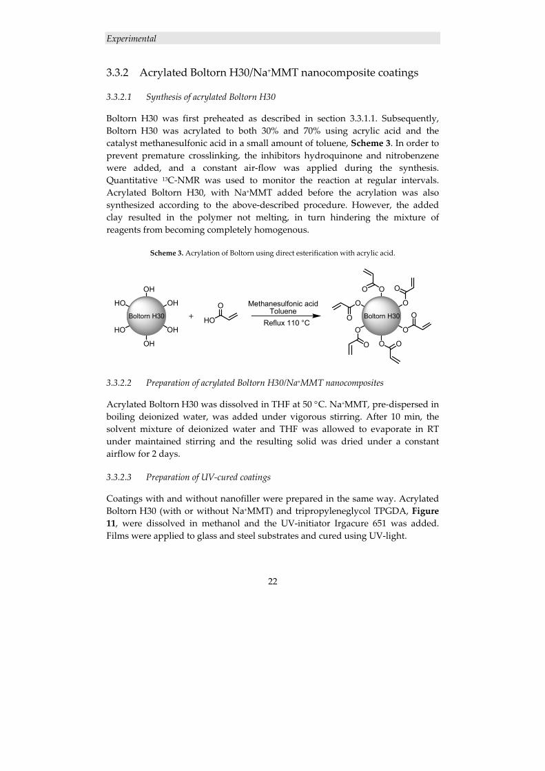
Boltorn H30 was first preheated as described in section 3.3.1.1. Subsequently, Boltorn H30 was acrylated to both 30% and 70% using acrylic acid and the catalyst methanesulfonic acid in a small amount of toluene, Scheme 3. In order to prevent premature crosslinking, the inhibitors hydroquinone and nitrobenzene were added, and a constant air‐flow was applied during the synthesis. Quantitative 13C‐NMR was used to monitor the reaction at regular intervals. Acrylated Boltorn H30, with Na+MMT added before the acrylation was also synthesized according to the above‐described procedure. However, the added clay resulted in the polymer not melting, in turn hindering the mixture of reagents from becoming completely homogenous.
Scheme 3. Acrylation of Boltorn using direct esterification with acrylic acid.
OH
HO OH
OHHO
OH
Boltorn H30 HO
O+
Methanesulfonic acid Toluene
Reflux 110 °C
O
O O
OO
O
Boltorn H30
O
O
OO
O
O
3.3.2.2 Preparation of acrylated Boltorn H30/Na+MMT nanocomposites
Acrylated Boltorn H30 was dissolved in THF at 50 °C. Na+MMT, pre‐dispersed in boiling deionized water, was added under vigorous stirring. After 10 min, the solvent mixture of deionized water and THF was allowed to evaporate in RT under maintained stirring and the resulting solid was dried under a constant airflow for 2 days.
3.3.2.3 Preparation of UV‐cured coatings
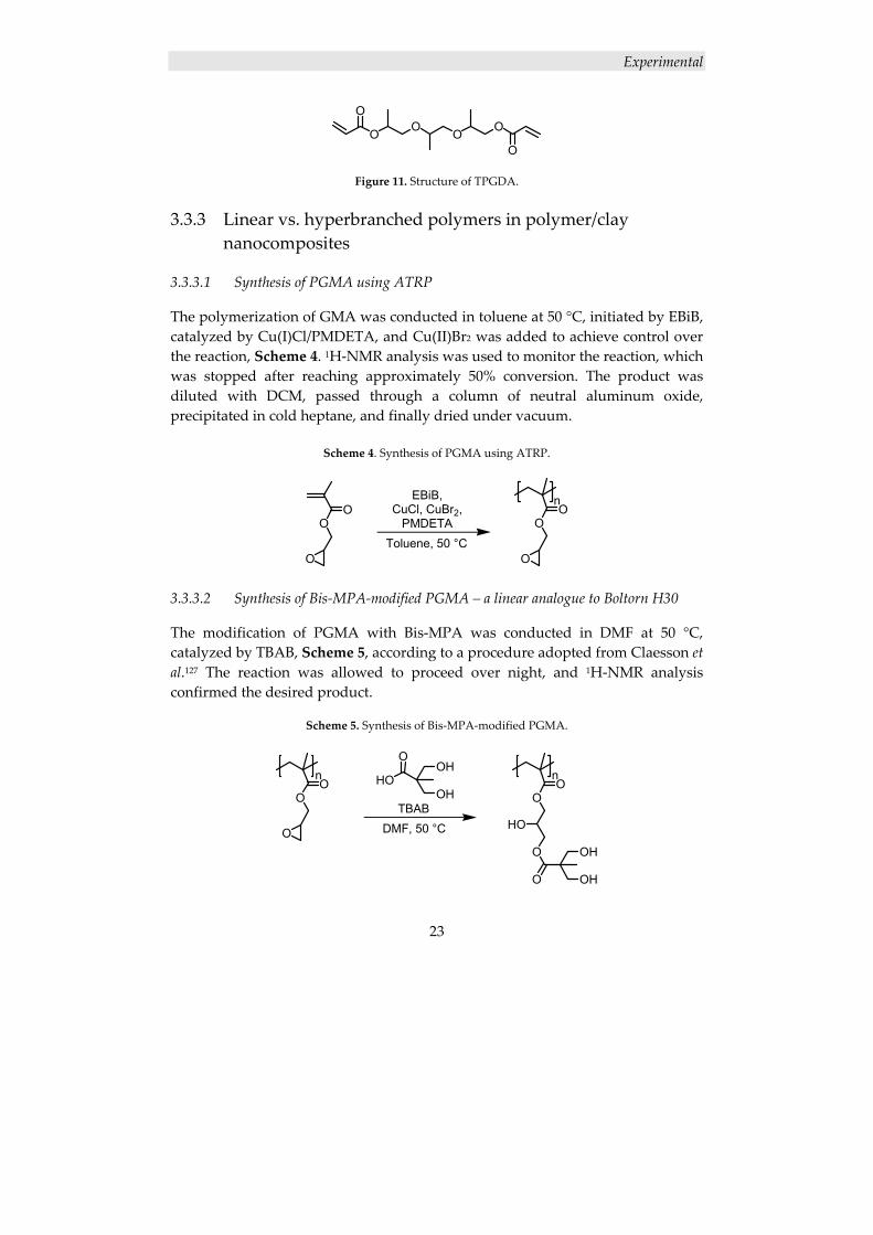
Coatings with and without nanofiller were prepared in the same way. Acrylated Boltorn H30 (with or without Na+MMT) and tripropyleneglycol TPGDA, Figure 11, were dissolved in methanol and the UV‐initiator Irgacure 651 was added. Films were applied to glass and steel substrates and cured using UV‐light.
Experimental
23
O O O O
O
O
Figure 11. Structure of TPGDA.
3.3.3 Linear vs. hyperbranched polymers in polymer/clay nanocomposites
3.3.3.1 Synthesis of PGMA using ATRP
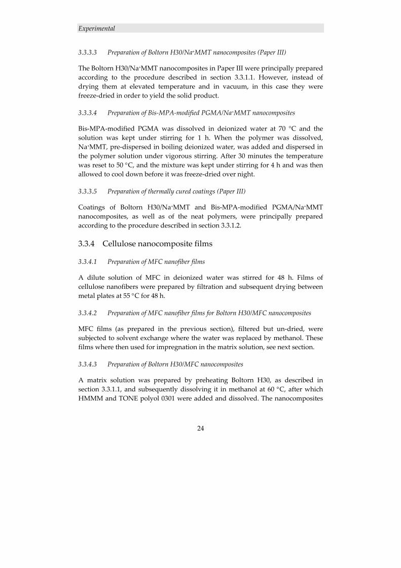
The polymerization of GMA was conducted in toluene at 50 °C, initiated by EBiB, catalyzed by Cu(I)Cl/PMDETA, and Cu(II)Br2 was added to achieve control over the reaction, Scheme 4. 1H‐NMR analysis was used to monitor the reaction, which was stopped after reaching approximately 50% conversion. The product was diluted with DCM, passed through a column of neutral aluminum oxide, precipitated in cold heptane, and finally dried under vacuum.
Scheme 4. Synthesis of PGMA using ATRP.
OO
O
EBiB, CuCl, CuBr2,
PMDETAToluene, 50 °C
OO
n
O
3.3.3.2 Synthesis of Bis‐MPA‐modified PGMA – a linear analogue to Boltorn H30
The modification of PGMA with Bis‐MPA was conducted in DMF at 50 °C, catalyzed by TBAB, Scheme 5, according to a procedure adopted from Claesson et al.127 The reaction was allowed to proceed over night, and 1H‐NMR analysis confirmed the desired product.
Scheme 5. Synthesis of Bis‐MPA‐modified PGMA.
TBABDMF, 50 °C
OO
n
O
OO
n
HO
O OH
OHO
HO
OOH
OH
Experimental
24
3.3.3.3 Preparation of Boltorn H30/Na+MMT nanocomposites (Paper III)
The Boltorn H30/Na+MMT nanocomposites in Paper III were principally prepared according to the procedure described in section 3.3.1.1. However, instead of drying them at elevated temperature and in vacuum, in this case they were freeze‐dried in order to yield the solid product.
3.3.3.4 Preparation of Bis‐MPA‐modified PGMA/Na+MMT nanocomposites
Bis‐MPA‐modified PGMA was dissolved in deionized water at 70 °C and the solution was kept under stirring for 1 h. When the polymer was dissolved, Na+MMT, pre‐dispersed in boiling deionized water, was added and dispersed in the polymer solution under vigorous stirring. After 30 minutes the temperature was reset to 50 °C, and the mixture was kept under stirring for 4 h and was then allowed to cool down before it was freeze‐dried over night.
3.3.3.5 Preparation of thermally cured coatings (Paper III)
Coatings of Boltorn H30/Na+MMT and Bis‐MPA‐modified PGMA/Na+MMT nanocomposites, as well as of the neat polymers, were principally prepared according to the procedure described in section 3.3.1.2.
3.3.4 Cellulose nanocomposite films
3.3.4.1 Preparation of MFC nanofiber films
A dilute solution of MFC in deionized water was stirred for 48 h. Films of cellulose nanofibers were prepared by filtration and subsequent drying between metal plates at 55 °C for 48 h.
3.3.4.2 Preparation of MFC nanofiber films for Boltorn H30/MFC nanocomposites
MFC films (as prepared in the previous section), filtered but un‐dried, were subjected to solvent exchange where the water was replaced by methanol. These films where then used for impregnation in the matrix solution, see next section.
3.3.4.3 Preparation of Boltorn H30/MFC nanocomposites
A matrix solution was prepared by preheating Boltorn H30, as described in section 3.3.1.1, and subsequently dissolving it in methanol at 60 °C, after which HMMM and TONE polyol 0301 were added and dissolved. The nanocomposites
Experimental
25
were prepared by impregnating un‐dried, methanol‐containing MFC films with the matrix solution in a vacuum desiccator for 24 h. The films were removed from the matrix solution, and dried between metal plates at 55 °C for 24 h in order to remove the methanol. Finally the films were hot‐pressed at 140 °C and 10 MPa for 20 minutes, during which the matrix was crosslinked.
3.3.5 Surface modification of cellulose nanofibers
3.3.5.1 Grafting of PCL from MFC using ROP
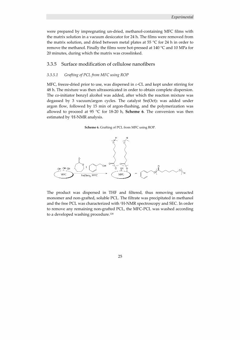
MFC, freeze‐dried prior to use, was dispersed in ε‐CL and kept under stirring for 48 h. The mixture was then ultrasonicated in order to obtain complete dispersion. The co‐initiator benzyl alcohol was added, after which the reaction mixture was degassed by 3 vacuum/argon cycles. The catalyst Sn(Oct)2 was added under argon flow, followed by 15 min of argon‐flushing, and the polymerization was allowed to proceed at 95 °C for 18‐20 h, Scheme 6. The conversion was then estimated by 1H‐NMR analysis.
Scheme 6. Grafting of PCL from MFC using ROP.
The product was dispersed in THF and filtered, thus removing unreacted monomer and non‐grafted, soluble PCL. The filtrate was precipitated in methanol and the free PCL was characterized with 1H‐NMR spectroscopy and SEC. In order to remove any remaining non‐grafted PCL, the MFC‐PCL was washed according to a developed washing procedure.128
Experimental
26
3.3.6 Cellulose nanocomposite laminates
3.3.6.1 Grafting of PCL from MFC nanofiber films using ROP
PCL‐grafted MFC films with different target DPs were prepared. Pre‐dried MFC films were immersed in ε‐CL and toluene, after which benzyl alcohol was added to the solution. To remove a majority of the remaining water, part of the toluene was distilled off before the catalyst Sn(Oct)2 was added to the system under argon flow. The polymerization was allowed to proceed at 95 °C for 16–18 h, similarly to Scheme 6. Subsequently, the free PCL was dissolved in THF and precipitated in cold methanol. In order to remove physically adsorbed but ungrafted PCL, the PCL‐grafted MFC films were thoroughly washed with soxhlet extraction in THF before characterization.
3.3.6.2 Preparation of PCL‐film and PCL‐MFC bilayer laminates
PCL films were prepared by solvent casting from THF. The bilayer laminates of MFC‐PCL films and PCL films were prepared by hot‐pressing at 120 °C.
Results and Discussion
27
4. RESULTS AND DISCUSSION
4.1 POLYMER/CLAY NANOCOMPOSITES
This part of the thesis focuses on the preparation and characterization of polymer/clay nanocomposites – more specifically Na+MMT in the hyperbranched polymer Boltorn H30 and derivatives thereof – and their use in coating applications. Nanocomposites were prepared from neat Boltorn H30 to yield resins for thermally cured coatings, from acrylated Boltorn H30 to yield resins for UV‐cured coatings, and from a linear analogue to Boltorn H30 in order to perform the comparative study on linear vs. hyperbranched polymers and their efficiency in nanocomposite preparation.
4.1.1 Boltorn H30/Na+MMT nanocomposite coatings
Nanocomposites of Boltorn H30 with different clay loadings were prepared and subsequently coatings were prepared from the nanocomposite resins, as well as from neat Boltorn H30, using HMMM as crosslinker in all formulations. The polyol TONE 0301 was added to increase the flexibility of the coating in order to facilitate the investigation of the influence of the nanofiller; since the nanofiller mainly affects the rubber plateau, the influence will be larger on soft and flexible materials. To avoid premature crosslinking, a blocked version of the catalyst pTSA was used, which is not activated until subjected to higher temperatures, i.e., in the curing oven. Texanol was, based on trade knowledge, added to facilitate the film‐forming process, in order to obtain uniform and smooth films. Three different coatings were prepared, with 0, 1 and 3 wt% clay, respectively.
4.1.1.1 Nanocomposite characterization
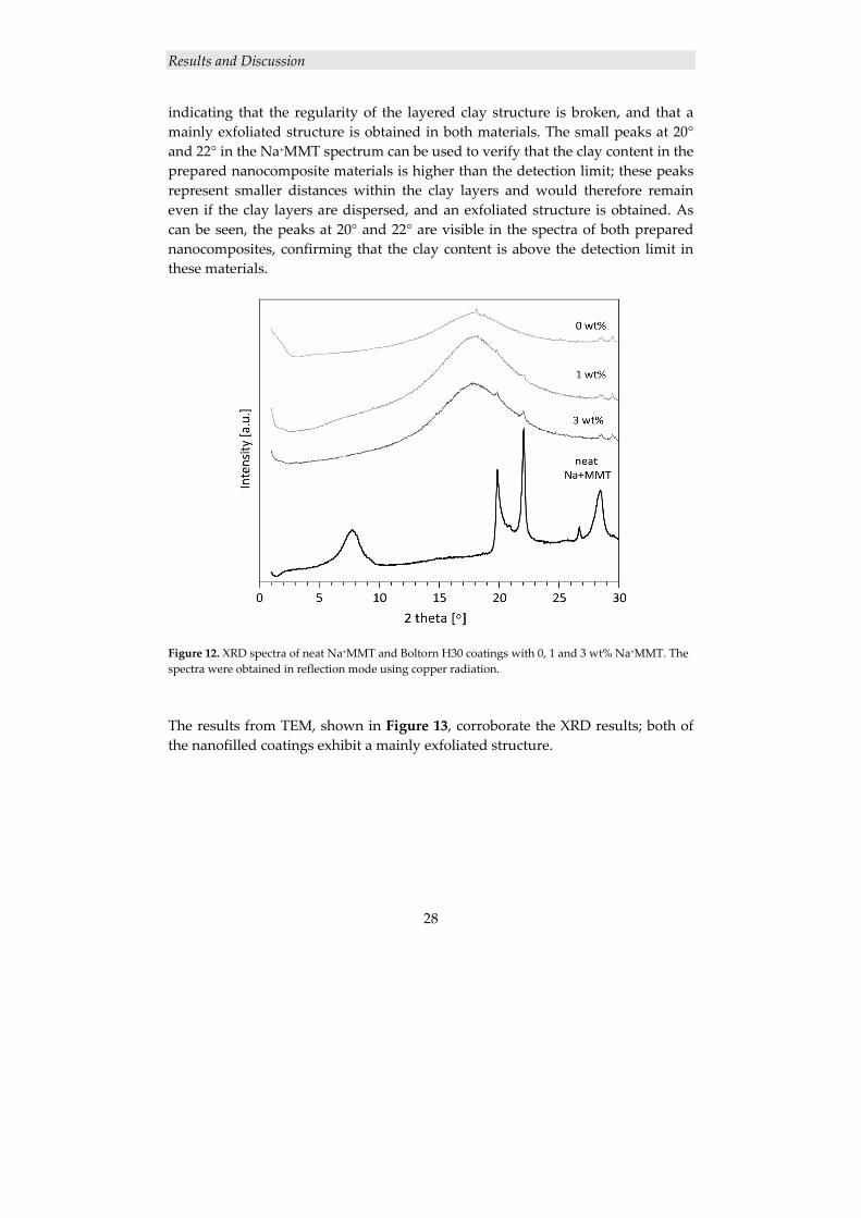
The dispersion of the clay layers in the nanofilled coatings was investigated with XRD and TEM. The large peak at 8° in the XRD spectrum of neat Na+MMT in Figure 12 represents the regular distance between the clay layers. This peak cannot be seen in any of the spectra of the prepared nanocomposites, strongly
Results and Discussion
28
indicating that the regularity of the layered clay structure is broken, and that a mainly exfoliated structure is obtained in both materials. The small peaks at 20° and 22° in the Na+MMT spectrum can be used to verify that the clay content in the prepared nanocomposite materials is higher than the detection limit; these peaks represent smaller distances within the clay layers and would therefore remain even if the clay layers are dispersed, and an exfoliated structure is obtained. As can be seen, the peaks at 20° and 22° are visible in the spectra of both prepared nanocomposites, confirming that the clay content is above the detection limit in these materials.
Figure 12. XRD spectra of neat Na+MMT and Boltorn H30 coatings with 0, 1 and 3 wt% Na+MMT. The spectra were obtained in reflection mode using copper radiation.
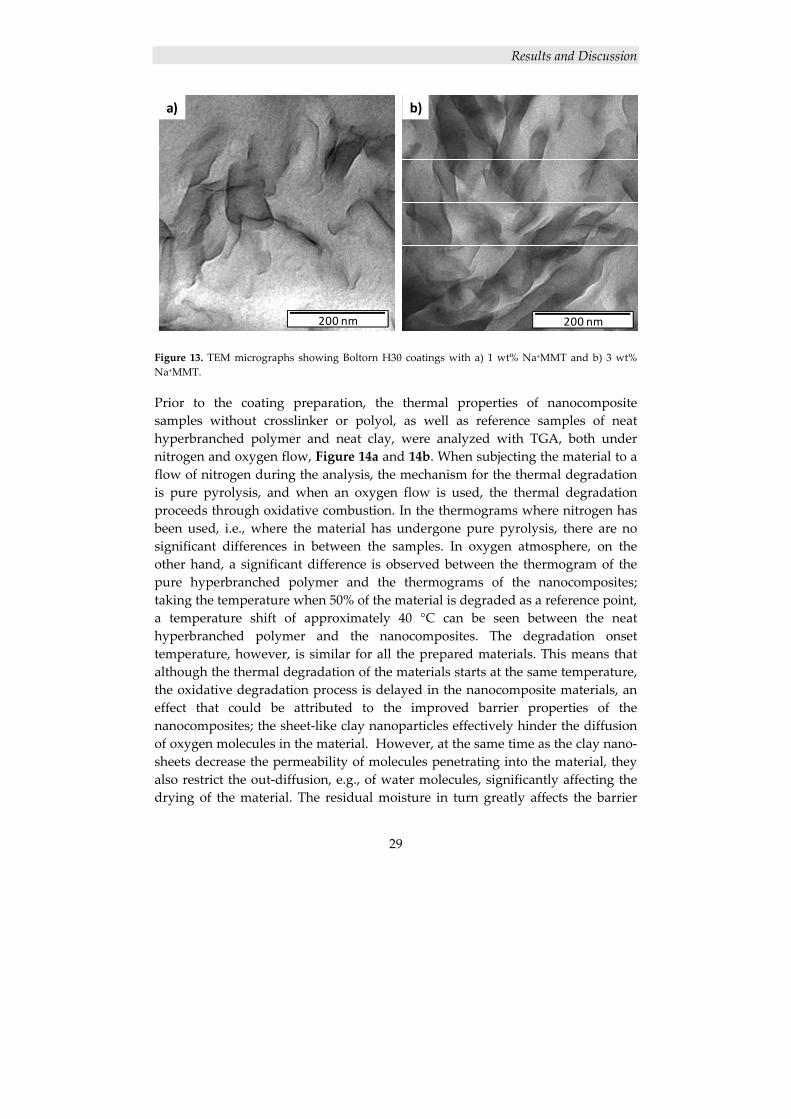
The results from TEM, shown in Figure 13, corroborate the XRD results; both of the nanofilled coatings exhibit a mainly exfoliated structure.
Results and Discussion
29
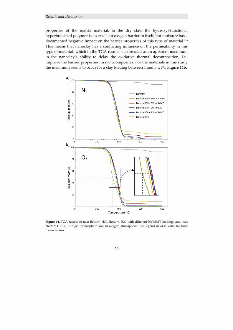
Figure 13. TEM micrographs showing Boltorn H30 coatings with a) 1 wt% Na+MMT and b) 3 wt% Na+MMT. Prior to the coating preparation, the thermal properties of nanocomposite samples without crosslinker or polyol, as well as reference samples of neat hyperbranched polymer and neat clay, were analyzed with TGA, both under nitrogen and oxygen flow, Figure 14a and 14b. When subjecting the material to a flow of nitrogen during the analysis, the mechanism for the thermal degradation is pure pyrolysis, and when an oxygen flow is used, the thermal degradation proceeds through oxidative combustion. In the thermograms where nitrogen has been used, i.e., where the material has undergone pure pyrolysis, there are no significant differences in between the samples. In oxygen atmosphere, on the other hand, a significant difference is observed between the thermogram of the pure hyperbranched polymer and the thermograms of the nanocomposites; taking the temperature when 50% of the material is degraded as a reference point, a temperature shift of approximately 40 °C can be seen between the neat hyperbranched polymer and the nanocomposites. The degradation onset temperature, however, is similar for all the prepared materials. This means that although the thermal degradation of the materials starts at the same temperature, the oxidative degradation process is delayed in the nanocomposite materials, an effect that could be attributed to the improved barrier properties of the nanocomposites; the sheet‐like clay nanoparticles effectively hinder the diffusion of oxygen molecules in the material. However, at the same time as the clay nano‐sheets decrease the permeability of molecules penetrating into the material, they also restrict the out‐diffusion, e.g., of water molecules, significantly affecting the drying of the material. The residual moisture in turn greatly affects the barrier
a) b)
200 nm 200 nm
Results and Discussion
30
properties of the matrix material; in the dry state the hydroxyl‐functional hyperbranched polymer is an excellent oxygen barrier in itself, but moisture has a documented negative impact on the barrier properties of this type of material.129 This means that nanoclay has a conflicting influence on the permeability in this type of material, which in the TGA results is expressed as an apparent maximum in the nanoclay’s ability to delay the oxidative thermal decomposition, i.e., improve the barrier properties, in nanocomposites. For the materials in this study the maximum seems to occur for a clay loading between 1 and 5 wt%, Figure 14b.
Figure 14. TGA results of neat Boltorn H30, Boltorn H30 with different Na+MMT loadings and neat Na+MMT in a) nitrogen atmosphere and b) oxygen atmosphere. The legend in a) is valid for both thermograms.
Results and Discussion
31
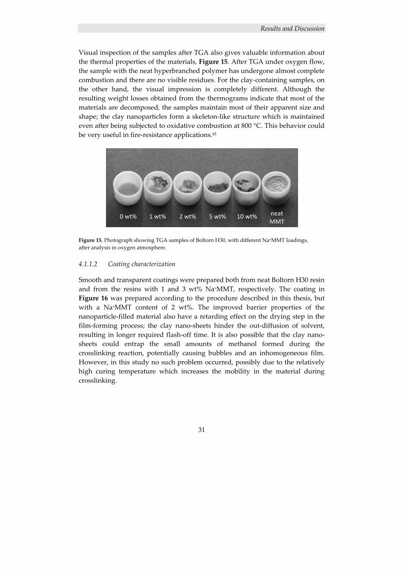
Visual inspection of the samples after TGA also gives valuable information about the thermal properties of the materials, Figure 15. After TGA under oxygen flow, the sample with the neat hyperbranched polymer has undergone almost complete combustion and there are no visible residues. For the clay‐containing samples, on the other hand, the visual impression is completely different. Although the resulting weight losses obtained from the thermograms indicate that most of the materials are decomposed, the samples maintain most of their apparent size and shape; the clay nanoparticles form a skeleton‐like structure which is maintained even after being subjected to oxidative combustion at 800 °C. This behavior could be very useful in fire‐resistance applications.43
Figure 15. Photograph showing TGA samples of Boltorn H30, with different Na+MMT loadings, after analysis in oxygen atmosphere.
4.1.1.2 Coating characterization
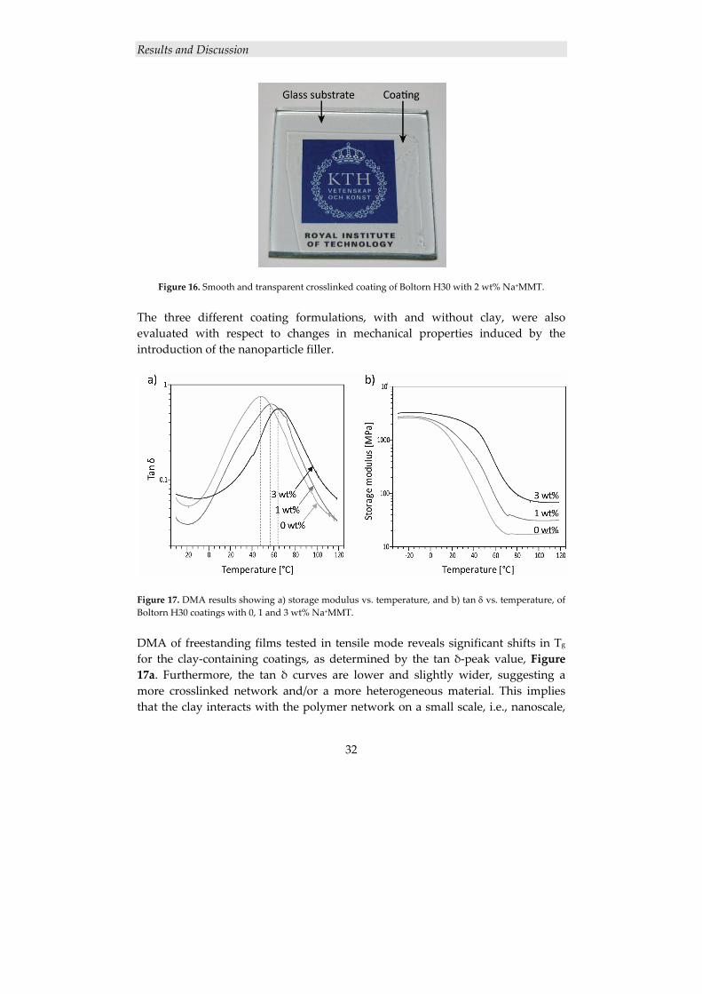
Smooth and transparent coatings were prepared both from neat Boltorn H30 resin and from the resins with 1 and 3 wt% Na+MMT, respectively. The coating in Figure 16 was prepared according to the procedure described in this thesis, but with a Na+MMT content of 2 wt%. The improved barrier properties of the nanoparticle‐filled material also have a retarding effect on the drying step in the film‐forming process; the clay nano‐sheets hinder the out‐diffusion of solvent, resulting in longer required flash‐off time. It is also possible that the clay nano‐sheets could entrap the small amounts of methanol formed during the crosslinking reaction, potentially causing bubbles and an inhomogeneous film. However, in this study no such problem occurred, possibly due to the relatively high curing temperature which increases the mobility in the material during crosslinking.
Results and Discussion
32
Figure 16. Smooth and transparent crosslinked coating of Boltorn H30 with 2 wt% Na+MMT. The three different coating formulations, with and without clay, were also evaluated with respect to changes in mechanical properties induced by the introduction of the nanoparticle filler.
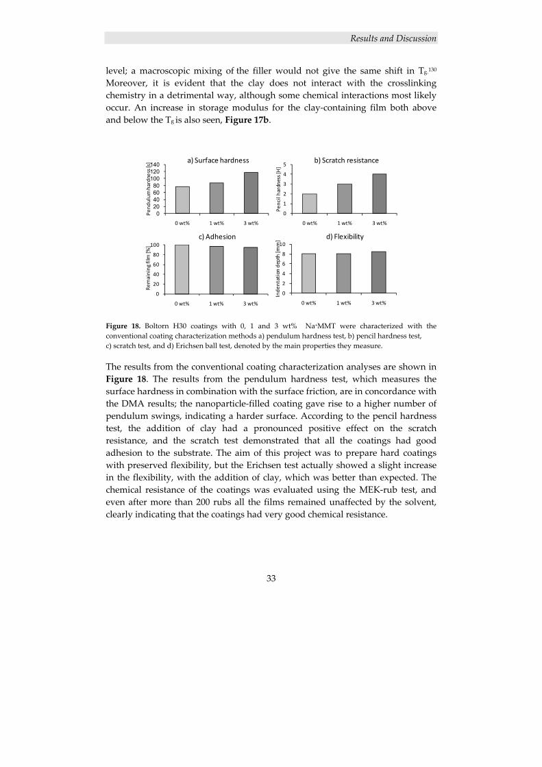
Figure 17. DMA results showing a) storage modulus vs. temperature, and b) tan δ vs. temperature, of Boltorn H30 coatings with 0, 1 and 3 wt% Na+MMT. DMA of freestanding films tested in tensile mode reveals significant shifts in Tg
for the clay‐containing coatings, as determined by the tan δ‐peak value, Figure 17a. Furthermore, the tan δ curves are lower and slightly wider, suggesting a more crosslinked network and/or a more heterogeneous material. This implies that the clay interacts with the polymer network on a small scale, i.e., nanoscale,
Results and Discussion
33
level; a macroscopic mixing of the filler would not give the same shift in Tg.130 Moreover, it is evident that the clay does not interact with the crosslinking chemistry in a detrimental way, although some chemical interactions most likely occur. An increase in storage modulus for the clay‐containing film both above and below the Tg is also seen, Figure 17b.
Figure 18. Boltorn H30 coatings with 0, 1 and 3 wt% Na+MMT were characterized with the conventional coating characterization methods a) pendulum hardness test, b) pencil hardness test, c) scratch test, and d) Erichsen ball test, denoted by the main properties they measure. The results from the conventional coating characterization analyses are shown in Figure 18. The results from the pendulum hardness test, which measures the surface hardness in combination with the surface friction, are in concordance with the DMA results; the nanoparticle‐filled coating gave rise to a higher number of pendulum swings, indicating a harder surface. According to the pencil hardness test, the addition of clay had a pronounced positive effect on the scratch resistance, and the scratch test demonstrated that all the coatings had good adhesion to the substrate. The aim of this project was to prepare hard coatings with preserved flexibility, but the Erichsen test actually showed a slight increase in the flexibility, with the addition of clay, which was better than expected. The chemical resistance of the coatings was evaluated using the MEK‐rub test, and even after more than 200 rubs all the films remained unaffected by the solvent, clearly indicating that the coatings had very good chemical resistance.
0
2
4
6
8
10
0 wt% 1 wt% 3 wt%
Inde
ntation depth [m
m] d) Flexibility
0
20
40
60
80
100
0 wt% 1 wt% 3 wt%
Remaining
film [%
]
c) Adhesion
020406080
100120140
0 wt% 1 wt% 3 wt%
Pend
ulum
hardness[s] a) Surface hardness
0
1
2
3
4
5
0 wt% 1 wt% 3 wt%
Pencilhardness[H]
b) Scratch resistance
Results and Discussion
34
4.1.2 Acrylated Boltorn H30/Na+MMT nanocomposite coatings
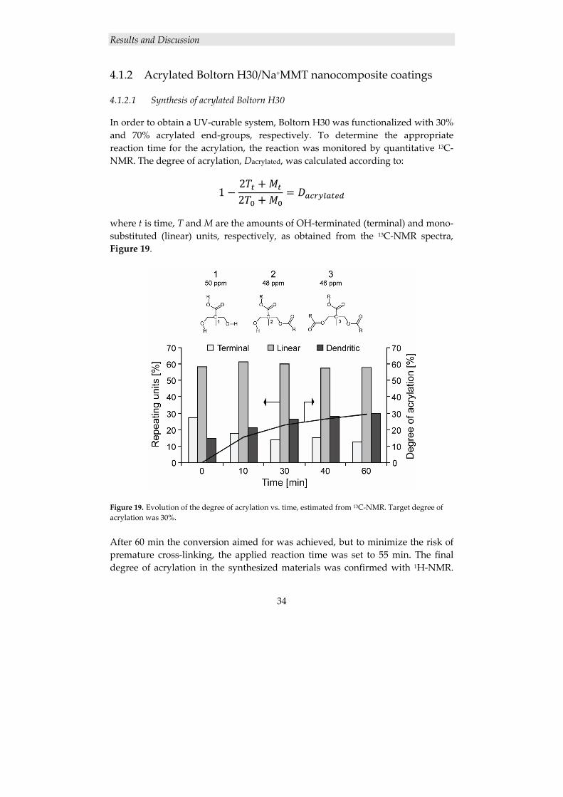
4.1.2.1 Synthesis of acrylated Boltorn H30
In order to obtain a UV‐curable system, Boltorn H30 was functionalized with 30% and 70% acrylated end‐groups, respectively. To determine the appropriate reaction time for the acrylation, the reaction was monitored by quantitative 13C‐NMR. The degree of acrylation, Dacrylated, was calculated according to:
122
where t is time, T and M are the amounts of OH‐terminated (terminal) and mono‐substituted (linear) units, respectively, as obtained from the 13C‐NMR spectra, Figure 19.
Figure 19. Evolution of the degree of acrylation vs. time, estimated from 13C‐NMR. Target degree of acrylation was 30%. After 60 min the conversion aimed for was achieved, but to minimize the risk of premature cross‐linking, the applied reaction time was set to 55 min. The final degree of acrylation in the synthesized materials was confirmed with 1H‐NMR.
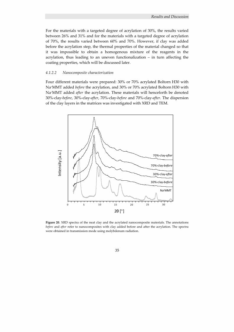
Results and Discussion
35
For the materials with a targeted degree of acrylation of 30%, the results varied between 26% and 31% and for the materials with a targeted degree of acrylation of 70%, the results varied between 60% and 70%. However, if clay was added before the acrylation step, the thermal properties of the material changed so that it was impossible to obtain a homogenous mixture of the reagents in the acrylation, thus leading to an uneven functionalization – in turn affecting the coating properties, which will be discussed later.
4.1.2.2 Nanocomposite characterization
Four different materials were prepared: 30% or 70% acrylated Boltorn H30 with Na+MMT added before the acrylation, and 30% or 70% acrylated Boltorn H30 with Na+MMT added after the acrylation. These materials will henceforth be denoted 30%‐clay‐before, 30%‐clay‐after, 70%‐clay‐before and 70%‐clay‐after. The dispersion of the clay layers in the matrices was investigated with XRD and TEM.
Figure 20. XRD spectra of the neat clay and the acrylated nanocomposite materials. The annotations before and after refer to nanocomposites with clay added before and after the acrylation. The spectra were obtained in transmission mode using molybdenum radiation.
0 5 10 15 20 25 30
30%‐clay‐before
Na+MMT
30%‐clay‐after
70%‐clay‐before
70%‐clay‐after
2θ [°]
Intensity
[a.u.]
0 5 10 15 20 25 30
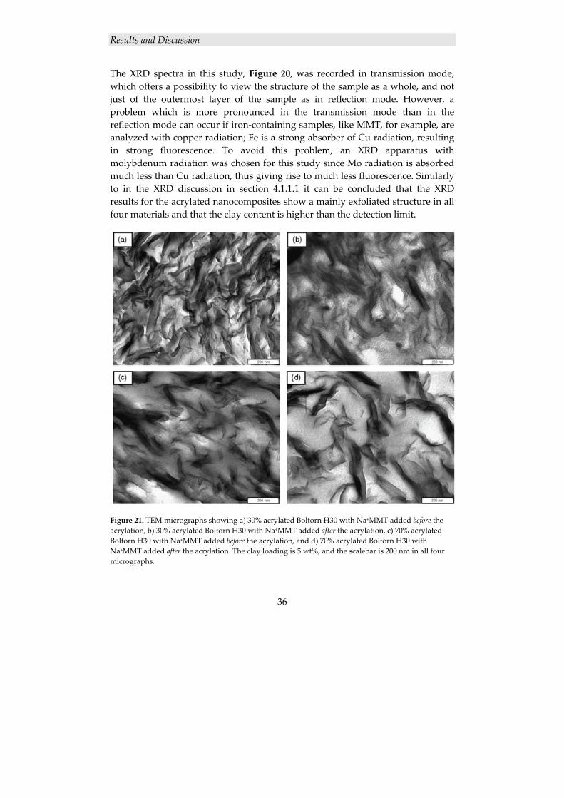
Results and Discussion
36
The XRD spectra in this study, Figure 20, was recorded in transmission mode, which offers a possibility to view the structure of the sample as a whole, and not just of the outermost layer of the sample as in reflection mode. However, a problem which is more pronounced in the transmission mode than in the reflection mode can occur if iron‐containing samples, like MMT, for example, are analyzed with copper radiation; Fe is a strong absorber of Cu radiation, resulting in strong fluorescence. To avoid this problem, an XRD apparatus with molybdenum radiation was chosen for this study since Mo radiation is absorbed much less than Cu radiation, thus giving rise to much less fluorescence. Similarly to in the XRD discussion in section 4.1.1.1 it can be concluded that the XRD results for the acrylated nanocomposites show a mainly exfoliated structure in all four materials and that the clay content is higher than the detection limit.
Figure 21. TEM micrographs showing a) 30% acrylated Boltorn H30 with Na+MMT added before the acrylation, b) 30% acrylated Boltorn H30 with Na+MMT added after the acrylation, c) 70% acrylated Boltorn H30 with Na+MMT added before the acrylation, and d) 70% acrylated Boltorn H30 with Na+MMT added after the acrylation. The clay loading is 5 wt%, and the scalebar is 200 nm in all four micrographs.
Results and Discussion
37
The results from TEM, Figure 21, corroborate the XRD results to a certain extent; all four materials exhibit some degree of exfoliation. However, a pronounced difference between the 30% acrylated materials and the 70% acrylated materials can be discerned, namely that the 30% acrylated materials seem to have a significantly higher degree of exfoliation. This is not unexpected since the 30% acrylated materials are more hydrophilic, owing to the larger amount of hydroxyl end‐groups remaining on the hyperbranched polymer, and therefore have a higher affinity for the clay, thus making the clay layers easier to disperse. On the other hand it is harder to draw conclusions regarding whether adding the clay before or after the acrylation renders the best result. Possibly, the materials with clay added before the acrylation have a slightly higher degree of exfoliation, which is yet again an expected consequence of the higher hydrophilicity of unmodified hydroxyl functional Boltorn H30, compared with the acrylated analogue.
4.1.2.3 Coating characterization
Six different coatings were prepared: from 30%‐clay‐before, 30%‐clay‐after, 70%‐clay‐before and from 70%‐clay‐after, and for comparison coatings were also prepared from 30% and 70% acrylated Boltorn H30 without nanofiller. The resulting clay loading was 2 wt% in all the clay‐containing coatings. Similarly to the thermally cured nanocomposite coatings, the acrylated nanocomposite coatings were also evaluated with conventional coating characterization methods, Figure 22. According to the pendulum hardness test the 30% acrylated Boltorn H30 film exhibited only a small improvement in hardness with the addition of clay before the acrylation, compared with the unfilled film, but the large improvement came with the addition of clay after the acrylation. This is arguably due to the fact that, although the degree of exfoliation was similar in both materials, the uneven acrylation when clay was added before the acrylation counteracted the positive effect of nanoparticle addition. The fact that the films with 70% acrylated Boltorn H30 generally had a harder surface than those with 30% acrylated Boltorn H30 was expected since there are more crosslinks in the 70%‐films, rendering the films harder. However, the addition of nanoparticles did not have any major effect on the 70%‐films regarding the surface hardness; the nanofiller mainly affects the rubber plateau, and consequently the influence of the nanofiller is larger on soft materials, such as the 30%‐films, than on harder materials, such as the 70%‐films. According to the pencil hardness test, the addition of clay before the acrylation gave rise to a deterioration of the scratch resistance, for both the 30% and the 70% acrylated Boltorn H30 films, which is arguably due to the uneven acrylation in those materials. On the other hand, the
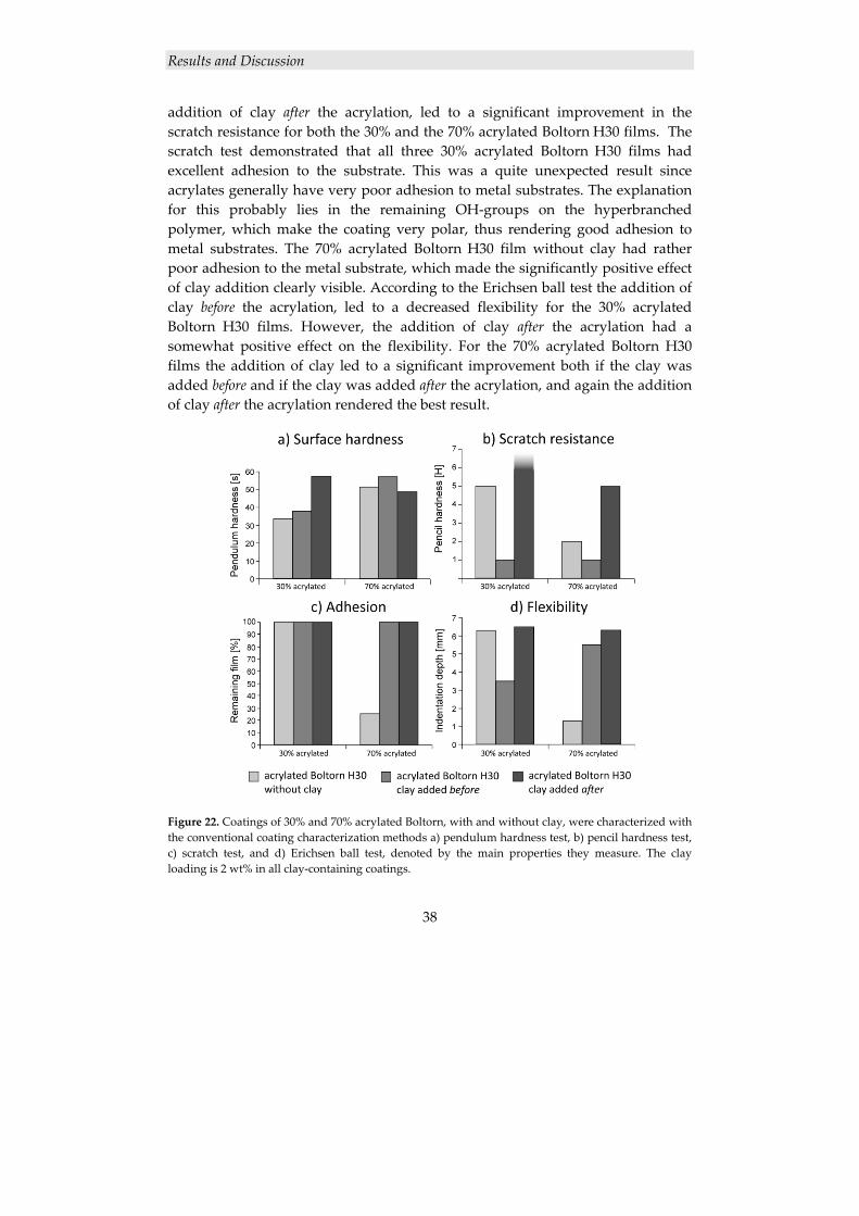
Results and Discussion
38
addition of clay after the acrylation, led to a significant improvement in the scratch resistance for both the 30% and the 70% acrylated Boltorn H30 films. The scratch test demonstrated that all three 30% acrylated Boltorn H30 films had excellent adhesion to the substrate. This was a quite unexpected result since acrylates generally have very poor adhesion to metal substrates. The explanation for this probably lies in the remaining OH‐groups on the hyperbranched polymer, which make the coating very polar, thus rendering good adhesion to metal substrates. The 70% acrylated Boltorn H30 film without clay had rather poor adhesion to the metal substrate, which made the significantly positive effect of clay addition clearly visible. According to the Erichsen ball test the addition of clay before the acrylation, led to a decreased flexibility for the 30% acrylated Boltorn H30 films. However, the addition of clay after the acrylation had a somewhat positive effect on the flexibility. For the 70% acrylated Boltorn H30 films the addition of clay led to a significant improvement both if the clay was added before and if the clay was added after the acrylation, and again the addition of clay after the acrylation rendered the best result.
Figure 22. Coatings of 30% and 70% acrylated Boltorn, with and without clay, were characterized with the conventional coating characterization methods a) pendulum hardness test, b) pencil hardness test, c) scratch test, and d) Erichsen ball test, denoted by the main properties they measure. The clay loading is 2 wt% in all clay‐containing coatings.
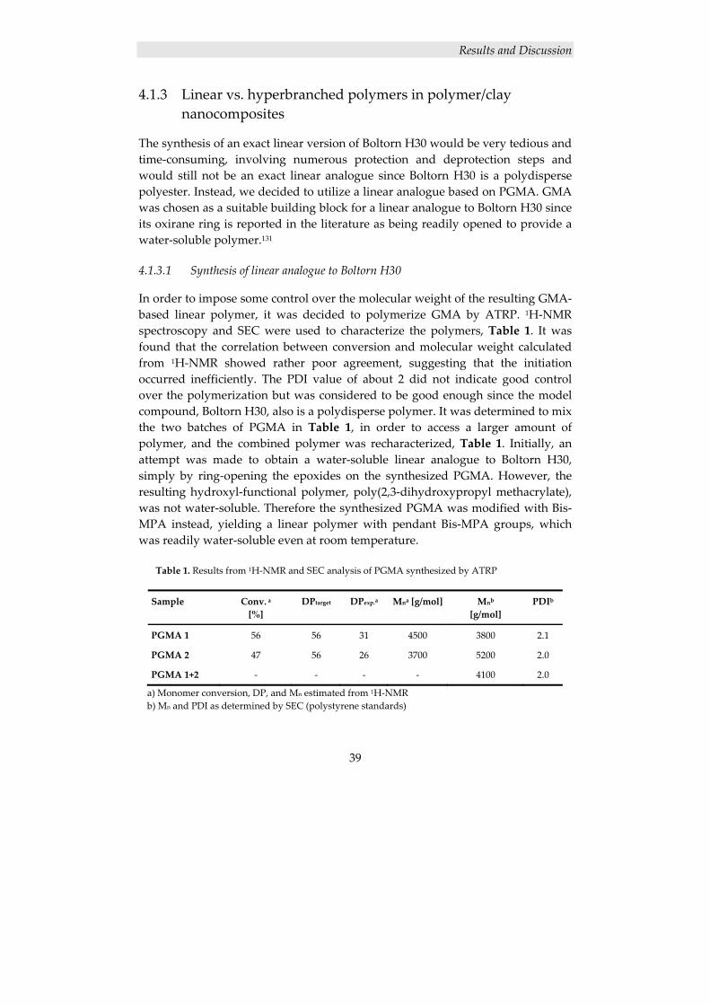
Results and Discussion
39
4.1.3 Linear vs. hyperbranched polymers in polymer/clay nanocomposites
The synthesis of an exact linear version of Boltorn H30 would be very tedious and time‐consuming, involving numerous protection and deprotection steps and would still not be an exact linear analogue since Boltorn H30 is a polydisperse polyester. Instead, we decided to utilize a linear analogue based on PGMA. GMA was chosen as a suitable building block for a linear analogue to Boltorn H30 since its oxirane ring is reported in the literature as being readily opened to provide a water‐soluble polymer.131
4.1.3.1 Synthesis of linear analogue to Boltorn H30
In order to impose some control over the molecular weight of the resulting GMA‐based linear polymer, it was decided to polymerize GMA by ATRP. 1H‐NMR spectroscopy and SEC were used to characterize the polymers, Table 1. It was found that the correlation between conversion and molecular weight calculated from 1H‐NMR showed rather poor agreement, suggesting that the initiation occurred inefficiently. The PDI value of about 2 did not indicate good control over the polymerization but was considered to be good enough since the model compound, Boltorn H30, also is a polydisperse polymer. It was determined to mix the two batches of PGMA in Table 1, in order to access a larger amount of polymer, and the combined polymer was recharacterized, Table 1. Initially, an attempt was made to obtain a water‐soluble linear analogue to Boltorn H30, simply by ring‐opening the epoxides on the synthesized PGMA. However, the resulting hydroxyl‐functional polymer, poly(2,3‐dihydroxypropyl methacrylate), was not water‐soluble. Therefore the synthesized PGMA was modified with Bis‐MPA instead, yielding a linear polymer with pendant Bis‐MPA groups, which was readily water‐soluble even at room temperature.
Table 1. Results from 1H‐NMR and SEC analysis of PGMA synthesized by ATRP
Sample Conv. a [%]
DPtarget DPexp.a Mna [g/mol] Mnb
[g/mol] PDIb
PGMA 1 56 56 31 4500 3800 2.1
PGMA 2 47 56 26 3700 5200 2.0
PGMA 1+2 ‐ ‐ ‐ ‐ 4100 2.0
a) Monomer conversion, DP, and Mn estimated from 1H‐NMR b) Mn and PDI as determined by SEC (polystyrene standards)
Results and Discussion
40
4.1.3.2 Nanocomposite and film preparation
The method for preparing nanocomposites used in this work, solution intercalation with water as solvent, is a simple and straight‐forward method, without any requirements of prior clay modification. By using freeze‐drying, the method is further developed, as compared with earlier work described in the literature1, 47 into an even faster and less troublesome process. Furthermore, the freeze‐drying is hypothesized to aid the preservation of the exfoliated structure in the dried product. In order to facilitate the nanocomposite characterization, free‐standing crosslinked films were prepared from nanocomposites based on Boltorn H30 and Bis‐MPA‐modified PGMA. The formulations differed slightly between the linear and the the hyperbranched nanocomposite films. An increased amount of the polyol spacer TONE 0301 and a decreased amount of the crosslinker HMMM had to be used in the linear nanocomposite films in order to compensate for the otherwise stiffer material, owing to the larger number of crosslinkable hydroxyl groups per molecule in the linear polymer. As stated earlier, hyperbranched polymers have a lower viscosity compared with their linear counterparts. Accordingly, a larger amount of solvent had to be used in the preparation of the linear nanocomposite films.
4.1.3.3 Nanocomposite characterization
The dispersion of the clay layers in the crosslinked nanocomposite films was investigated with XRD and TEM. The XRD results are displayed in Figure 23. In all the nanocomposite spectra there are some artifacts at lower degrees, possibly from disturbance caused by incoming radiation at low degrees, radiating straight into the detector. The assumption that these apparent XRD signals are artifacts, rather than actual signals from the clay, is strengthen by comparing these XRD results with previously obtained results on materials prepared in the same way, in which no such signals are visible.47 The large peak at 8° in the XRD spectrum of pure clay, Na+MMT, represents the regular distance between the clay layers. This peak cannot be seen in any of the spectra of the Boltorn H30 nanocomposite films, which strongly indicates that the regularity of the layered clay structure is broken, and that a mainly exfoliated structure is obtained in both these materials. The XRD results for the Bis‐MPA‐modified nanocomposite films, on the other hand, show a remaining clay layer‐distance peak; however, it is smaller and shifted to approximately 6.5°. This means that some of the regularity of the layered clay structure is maintained, but that the interlayer distance has increased, indicating a mainly intercalated structure. Similarly to in the XRD
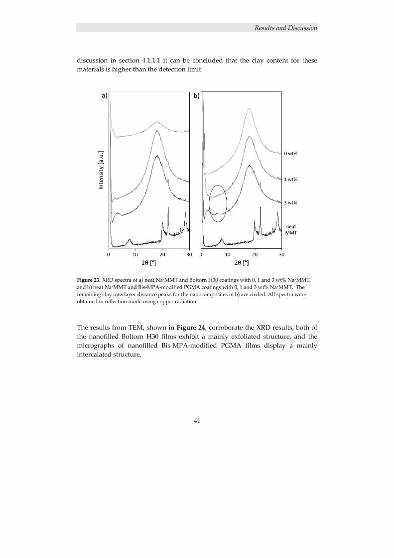
Results and Discussion
41
discussion in section 4.1.1.1 it can be concluded that the clay content for these materials is higher than the detection limit.
Figure 23. XRD spectra of a) neat Na+MMT and Boltorn H30 coatings with 0, 1 and 3 wt% Na+MMT, and b) neat Na+MMT and Bis‐MPA‐modified PGMA coatings with 0, 1 and 3 wt% Na+MMT. The remaining clay interlayer distance peaks for the nanocomposites in b) are circled. All spectra were obtained in reflection mode using copper radiation.
The results from TEM, shown in Figure 24, corroborate the XRD results; both of the nanofilled Boltorn H30 films exhibit a mainly exfoliated structure, and the micrographs of nanofilled Bis‐MPA‐modified PGMA films display a mainly intercalated structure.
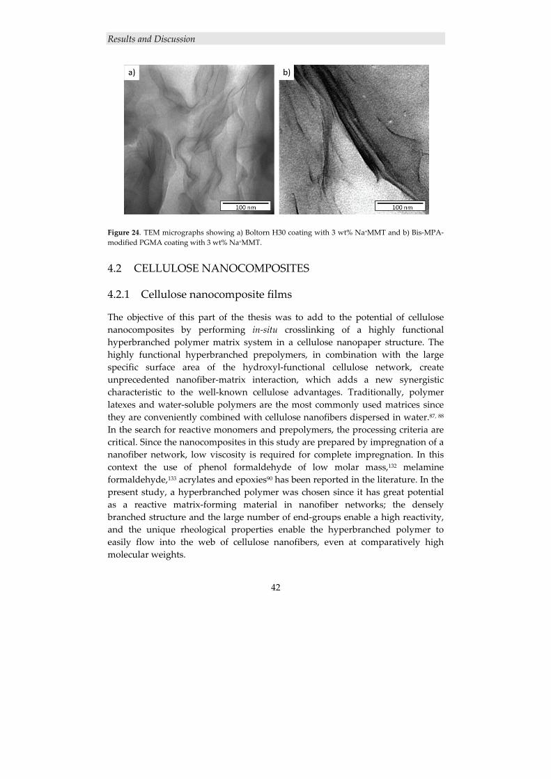
Results and Discussion
42
Figure 24. TEM micrographs showing a) Boltorn H30 coating with 3 wt% Na+MMT and b) Bis‐MPA‐modified PGMA coating with 3 wt% Na+MMT.
4.2 CELLULOSE NANOCOMPOSITES
4.2.1 Cellulose nanocomposite films
The objective of this part of the thesis was to add to the potential of cellulose nanocomposites by performing in‐situ crosslinking of a highly functional hyperbranched polymer matrix system in a cellulose nanopaper structure. The highly functional hyperbranched prepolymers, in combination with the large specific surface area of the hydroxyl‐functional cellulose network, create unprecedented nanofiber‐matrix interaction, which adds a new synergistic characteristic to the well‐known cellulose advantages. Traditionally, polymer latexes and water‐soluble polymers are the most commonly used matrices since they are conveniently combined with cellulose nanofibers dispersed in water.87, 88 In the search for reactive monomers and prepolymers, the processing criteria are critical. Since the nanocomposites in this study are prepared by impregnation of a nanofiber network, low viscosity is required for complete impregnation. In this context the use of phenol formaldehyde of low molar mass,132 melamine formaldehyde,133 acrylates and epoxies90 has been reported in the literature. In the present study, a hyperbranched polymer was chosen since it has great potential as a reactive matrix‐forming material in nanofiber networks; the densely branched structure and the large number of end‐groups enable a high reactivity, and the unique rheological properties enable the hyperbranched polymer to easily flow into the web of cellulose nanofibers, even at comparatively high molecular weights.
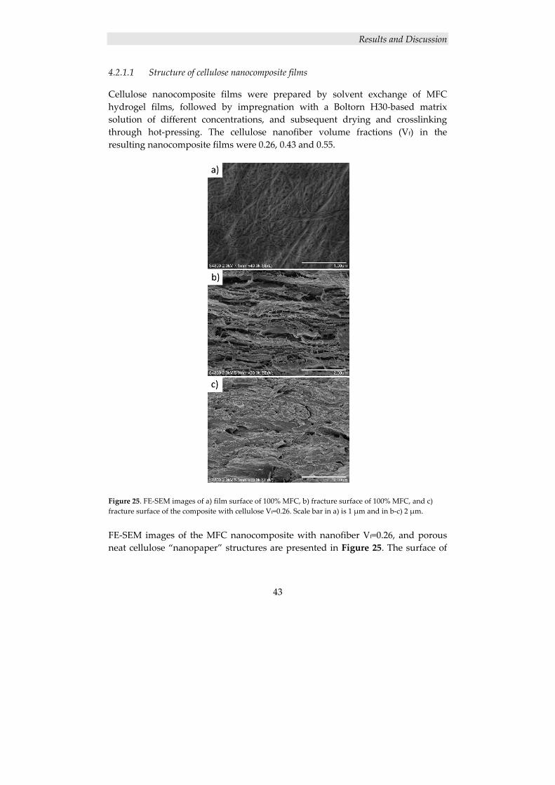
Results and Discussion
43
4.2.1.1 Structure of cellulose nanocomposite films
Cellulose nanocomposite films were prepared by solvent exchange of MFC hydrogel films, followed by impregnation with a Boltorn H30‐based matrix solution of different concentrations, and subsequent drying and crosslinking through hot‐pressing. The cellulose nanofiber volume fractions (Vf) in the resulting nanocomposite films were 0.26, 0.43 and 0.55.
Figure 25. FE‐SEM images of a) film surface of 100% MFC, b) fracture surface of 100% MFC, and c) fracture surface of the composite with cellulose Vf=0.26. Scale bar in a) is 1 μm and in b‐c) 2 μm. FE‐SEM images of the MFC nanocomposite with nanofiber Vf=0.26, and porous neat cellulose “nanopaper” structures are presented in Figure 25. The surface of
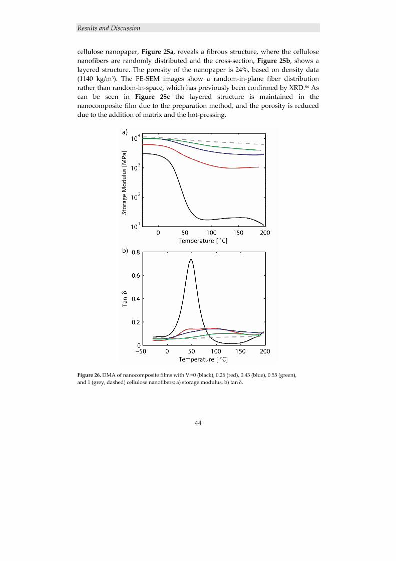
Results and Discussion
44
cellulose nanopaper, Figure 25a, reveals a fibrous structure, where the cellulose nanofibers are randomly distributed and the cross‐section, Figure 25b, shows a layered structure. The porosity of the nanopaper is 24%, based on density data (1140 kg/m3). The FE‐SEM images show a random‐in‐plane fiber distribution rather than random‐in‐space, which has previously been confirmed by XRD.86 As can be seen in Figure 25c the layered structure is maintained in the nanocomposite film due to the preparation method, and the porosity is reduced due to the addition of matrix and the hot‐pressing.
Figure 26. DMA of nanocomposite films with Vf=0 (black), 0.26 (red), 0.43 (blue), 0.55 (green), and 1 (grey, dashed) cellulose nanofibers; a) storage modulus, b) tan δ.
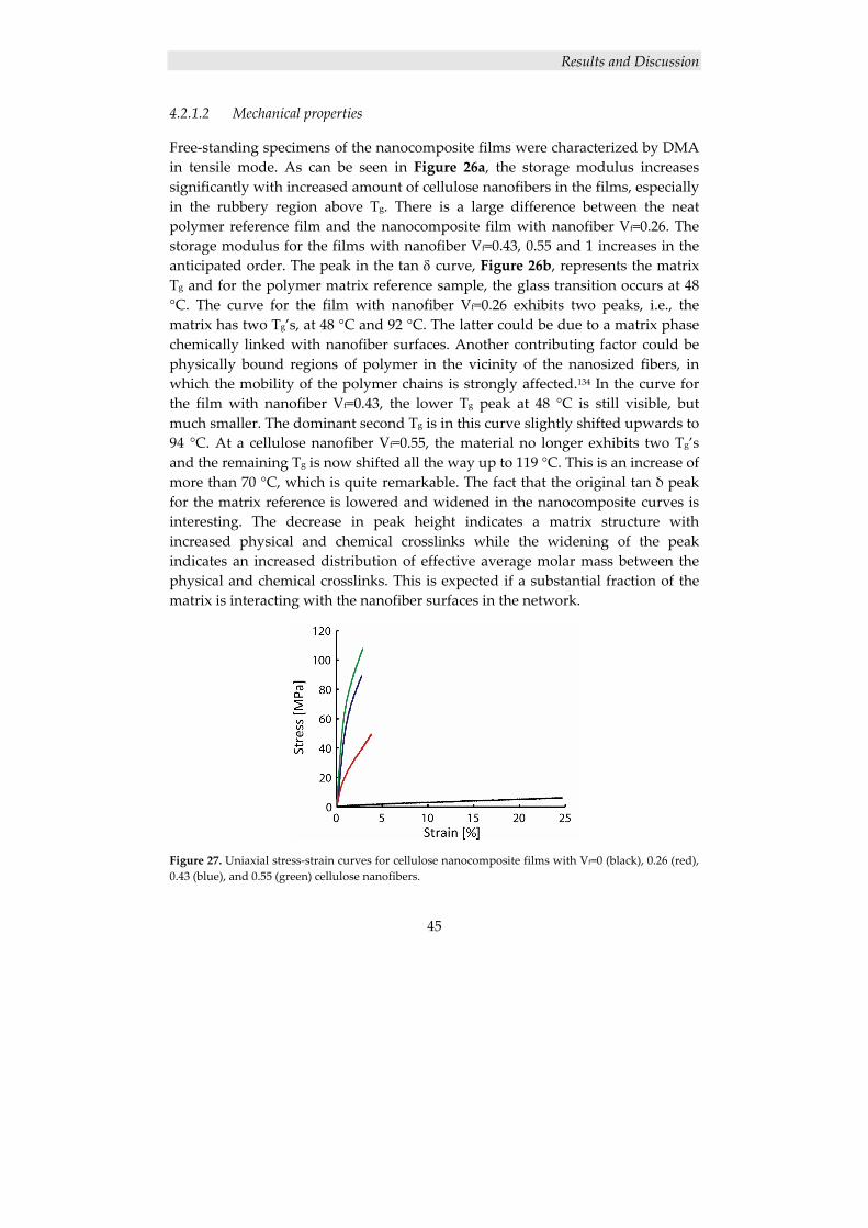
Results and Discussion
45
4.2.1.2 Mechanical properties
Free‐standing specimens of the nanocomposite films were characterized by DMA in tensile mode. As can be seen in Figure 26a, the storage modulus increases significantly with increased amount of cellulose nanofibers in the films, especially in the rubbery region above Tg. There is a large difference between the neat polymer reference film and the nanocomposite film with nanofiber Vf=0.26. The storage modulus for the films with nanofiber Vf=0.43, 0.55 and 1 increases in the anticipated order. The peak in the tan δ curve, Figure 26b, represents the matrix Tg and for the polymer matrix reference sample, the glass transition occurs at 48 °C. The curve for the film with nanofiber Vf=0.26 exhibits two peaks, i.e., the matrix has two Tg’s, at 48 °C and 92 °C. The latter could be due to a matrix phase chemically linked with nanofiber surfaces. Another contributing factor could be physically bound regions of polymer in the vicinity of the nanosized fibers, in which the mobility of the polymer chains is strongly affected.134 In the curve for the film with nanofiber Vf=0.43, the lower Tg peak at 48 °C is still visible, but much smaller. The dominant second Tg is in this curve slightly shifted upwards to 94 °C. At a cellulose nanofiber Vf=0.55, the material no longer exhibits two Tg’s and the remaining Tg is now shifted all the way up to 119 °C. This is an increase of more than 70 °C, which is quite remarkable. The fact that the original tan δ peak for the matrix reference is lowered and widened in the nanocomposite curves is interesting. The decrease in peak height indicates a matrix structure with increased physical and chemical crosslinks while the widening of the peak indicates an increased distribution of effective average molar mass between the physical and chemical crosslinks. This is expected if a substantial fraction of the matrix is interacting with the nanofiber surfaces in the network.
Figure 27. Uniaxial stress‐strain curves for cellulose nanocomposite films with Vf=0 (black), 0.26 (red), 0.43 (blue), and 0.55 (green) cellulose nanofibers.
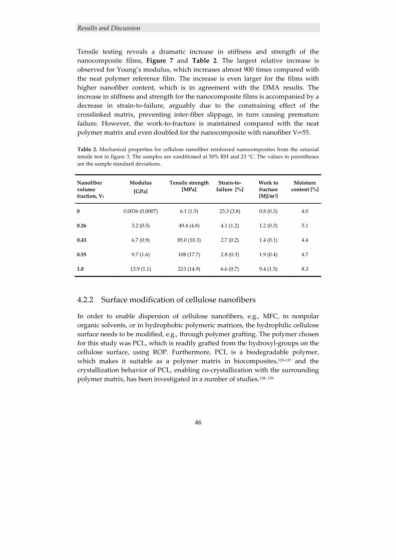
Results and Discussion
46
Tensile testing reveals a dramatic increase in stiffness and strength of the nanocomposite films, Figure 7 and Table 2. The largest relative increase is observed for Young’s modulus, which increases almost 900 times compared with the neat polymer reference film. The increase is even larger for the films with higher nanofiber content, which is in agreement with the DMA results. The increase in stiffness and strength for the nanocomposite films is accompanied by a decrease in strain‐to‐failure, arguably due to the constraining effect of the crosslinked matrix, preventing inter‐fiber slippage, in turn causing premature failure. However, the work‐to‐fracture is maintained compared with the neat polymer matrix and even doubled for the nanocomposite with nanofiber Vf=55. Table 2. Mechanical properties for cellulose nanofiber reinforced nanocomposites from the uniaxial tensile test in figure 3. The samples are conditioned at 50% RH and 23 °C. The values in parentheses are the sample standard deviations.
Nanofiber volume fraction, Vf
Modulus [GPa]
Tensile strength [MPa]
Strain‐to‐failure [%]
Work to fracture [MJ/m3]
Moisture content [%]
0 0.0036 (0.0007) 6.1 (1.5) 23.3 (3.8) 0.8 (0.3) 4.0
0.26 3.2 (0.5) 49.4 (4.8) 4.1 (1.2) 1.2 (0.3) 5.1
0.43 6.7 (0.9) 85.0 (10.3) 2.7 (0.2) 1.4 (0.1) 4.4
0.55 9.7 (1.6) 108 (17.7) 2.8 (0.3) 1.9 (0.4) 4.7
1.0 13.9 (1.1) 213 (14.9) 6.6 (0.7) 9.4 (1.5) 8.3
4.2.2 Surface modification of cellulose nanofibers
In order to enable dispersion of cellulose nanofibers, e.g., MFC, in nonpolar organic solvents, or in hydrophobic polymeric matrices, the hydrophilic cellulose surface needs to be modified, e.g., through polymer grafting. The polymer chosen for this study was PCL, which is readily grafted from the hydroxyl‐groups on the cellulose surface, using ROP. Furthermore, PCL is a biodegradable polymer, which makes it suitable as a polymer matrix in biocomposites,135‐137 and the crystallization behavior of PCL, enabling co‐crystallization with the surrounding polymer matrix, has been investigated in a number of studies.138, 139
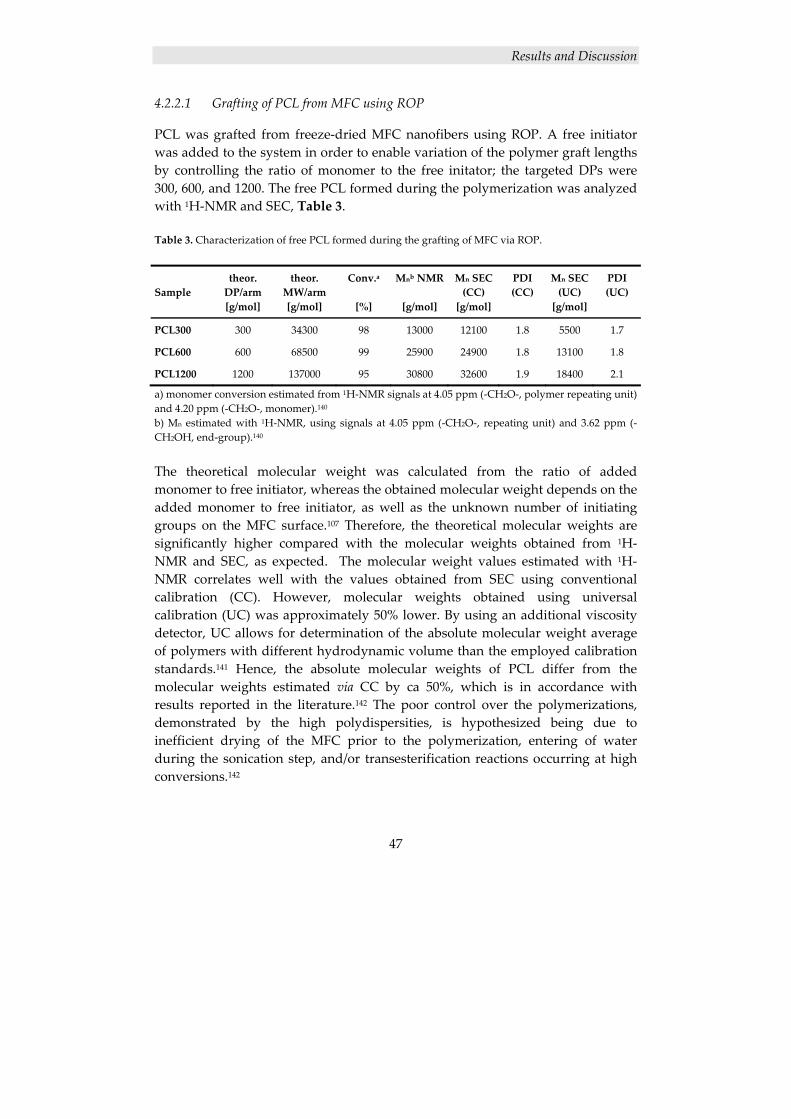
Results and Discussion
47
4.2.2.1 Grafting of PCL from MFC using ROP
PCL was grafted from freeze‐dried MFC nanofibers using ROP. A free initiator was added to the system in order to enable variation of the polymer graft lengths by controlling the ratio of monomer to the free initator; the targeted DPs were 300, 600, and 1200. The free PCL formed during the polymerization was analyzed with 1H‐NMR and SEC, Table 3. Table 3. Characterization of free PCL formed during the grafting of MFC via ROP. Sample
theor. DP/arm [g/mol]
theor. MW/arm [g/mol]
Conv.a
[%]
Mnb NMR
[g/mol]
Mn SEC(CC) [g/mol]
PDI(CC)
Mn SEC (UC) [g/mol]
PDI (UC)
PCL300 300 34300 98 13000 12100 1.8 5500 1.7
PCL600 600 68500 99 25900 24900 1.8 13100 1.8
PCL1200 1200 137000 95 30800 32600 1.9 18400 2.1
a) monomer conversion estimated from 1H‐NMR signals at 4.05 ppm (‐CH2O‐, polymer repeating unit) and 4.20 ppm (‐CH2O‐, monomer).140 b) Mn estimated with 1H‐NMR, using signals at 4.05 ppm (‐CH2O‐, repeating unit) and 3.62 ppm (‐CH2OH, end‐group).140 The theoretical molecular weight was calculated from the ratio of added monomer to free initiator, whereas the obtained molecular weight depends on the added monomer to free initiator, as well as the unknown number of initiating groups on the MFC surface.107 Therefore, the theoretical molecular weights are significantly higher compared with the molecular weights obtained from 1H‐NMR and SEC, as expected. The molecular weight values estimated with 1H‐NMR correlates well with the values obtained from SEC using conventional calibration (CC). However, molecular weights obtained using universal calibration (UC) was approximately 50% lower. By using an additional viscosity detector, UC allows for determination of the absolute molecular weight average of polymers with different hydrodynamic volume than the employed calibration standards.141 Hence, the absolute molecular weights of PCL differ from the molecular weights estimated via CC by ca 50%, which is in accordance with results reported in the literature.142 The poor control over the polymerizations, demonstrated by the high polydispersities, is hypothesized being due to inefficient drying of the MFC prior to the polymerization, entering of water during the sonication step, and/or transesterification reactions occurring at high conversions.142
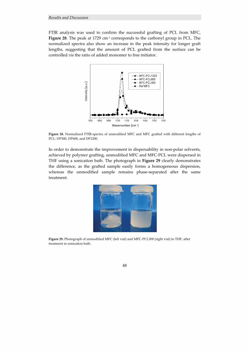
Results and Discussion
48
FTIR analysis was used to confirm the successful grafting of PCL from MFC, Figure 28. The peak at 1729 cm‐1 corresponds to the carbonyl group in PCL. The normalized spectra also show an increase in the peak intensity for longer graft lengths, suggesting that the amount of PCL grafted from the surface can be controlled via the ratio of added monomer to free initiator.
Figure 28. Normalized FTIR‐spectra of unmodified MFC and MFC grafted with different lengths of PCL: DP300, DP600, and DP1200. In order to demonstrate the improvement in dispersability in non‐polar solvents, achieved by polymer grafting, unmodified MFC and MFC‐PCL were dispersed in THF using a sonication bath. The photograph in Figure 29 clearly demonstrates the difference, as the grafted sample easily forms a homogeneous dispersion, whereas the unmodified sample remains phase‐separated after the same treatment.
Figure 29. Photograph of unmodified MFC (left vial) and MFC‐PCL300 (right vial) in THF, after treatment in sonication bath.
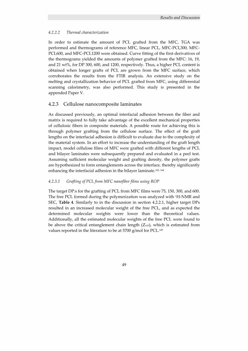
Results and Discussion
49
4.2.2.2 Thermal characterization
In order to estimate the amount of PCL grafted from the MFC, TGA was performed and thermograms of reference MFC, linear PCL, MFC‐PCL300, MFC‐PCL600, and MFC‐PCL1200 were obtained. Curve fitting of the first derivatives of the thermograms yielded the amounts of polymer grafted from the MFC: 16, 19, and 21 wt%, for DP 300, 600, and 1200, respectively. Thus, a higher PCL content is obtained when longer grafts of PCL are grown from the MFC surface, which corroborates the results from the FTIR analysis. An extensive study on the melting and crystallization behavior of PCL grafted from MFC, using differential scanning calorimetry, was also performed. This study is presented in the appended Paper V.
4.2.3 Cellulose nanocomposite laminates
As discussed previously, an optimal interfacial adhesion between the fiber and matrix is required to fully take advantage of the excellent mechanical properties of cellulosic fibers in composite materials. A possible route for achieving this is through polymer grafting from the cellulose surface. The effect of the graft lengths on the interfacial adhesion is difficult to evaluate due to the complexity of the material system. In an effort to increase the understanding of the graft length impact, model cellulose films of MFC were grafted with different lengths of PCL and bilayer laminates were subsequently prepared and evaluated in a peel test. Assuming sufficient molecular weight and grafting density, the polymer grafts are hypothesized to form entanglements across the interface, thereby significantly enhancing the interfacial adhesion in the bilayer laminate.143, 144
4.2.3.1 Grafting of PCL from MFC nanofiber films using ROP
The target DP:s for the grafting of PCL from MFC films were 75, 150, 300, and 600. The free PCL formed during the polymerization was analyzed with 1H‐NMR and SEC, Table 4. Similarly to in the discussion in section 4.2.2.1, higher target DPs resulted in an increased molecular weight of the free PCL, and as expected the determined molecular weights were lower than the theoretical values. Additionally, all the estimated molecular weights of the free PCL were found to be above the critical entanglement chain length (Zcrit), which is estimated from values reported in the literature to be at 5700 g/mol for PCL.145
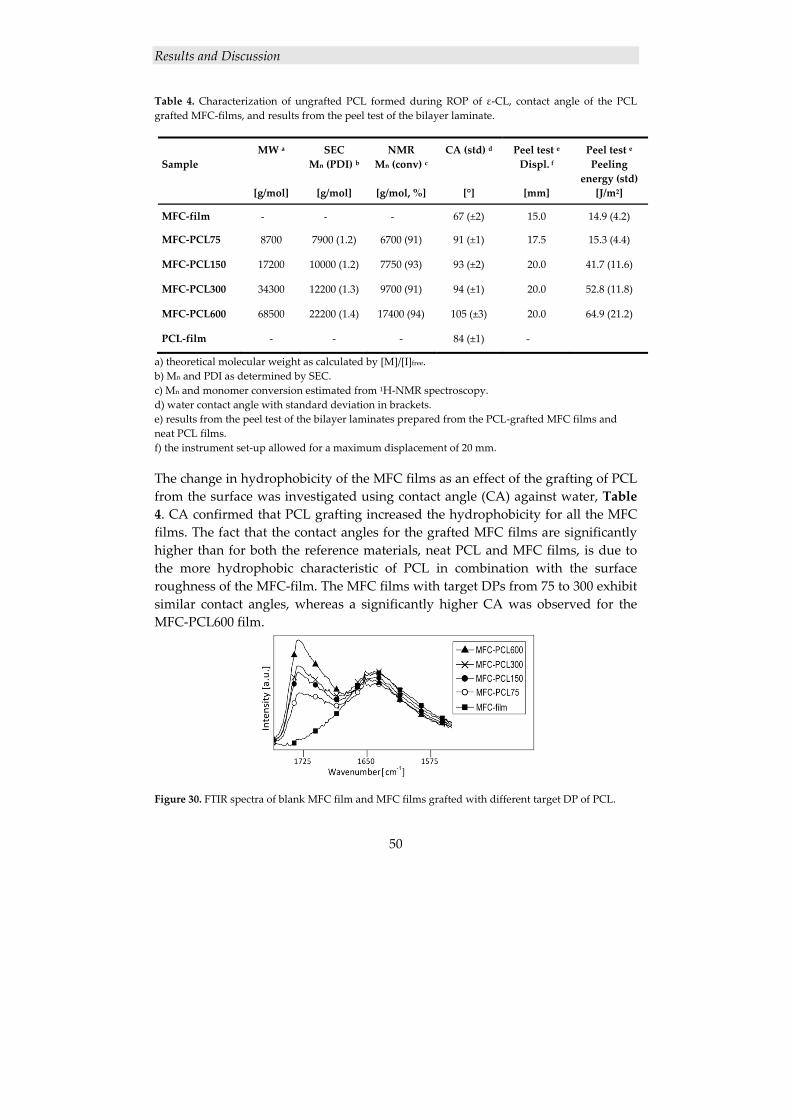
Results and Discussion
50
Table 4. Characterization of ungrafted PCL formed during ROP of ε‐CL, contact angle of the PCL grafted MFC‐films, and results from the peel test of the bilayer laminate.
Sample
MW a
[g/mol]
SECMn (PDI) b
[g/mol]
NMRMn (conv) c
[g/mol, %]
CA (std) d [°]
Peel test e Displ. f
[mm]
Peel test e Peeling
energy (std) [J/m2]
MFC‐film - - - 67 (±2) 15.0 14.9 (4.2)
MFC‐PCL75 8700 7900 (1.2) 6700 (91) 91 (±1) 17.5 15.3 (4.4)
MFC‐PCL150 17200 10000 (1.2) 7750 (93) 93 (±2) 20.0 41.7 (11.6)
MFC‐PCL300 34300 12200 (1.3) 9700 (91) 94 (±1) 20.0 52.8 (11.8)
MFC‐PCL600 68500 22200 (1.4) 17400 (94) 105 (±3) 20.0 64.9 (21.2)
PCL‐film ‐ ‐ ‐ 84 (±1) -
a) theoretical molecular weight as calculated by [M]/[I]free. b) Mn and PDI as determined by SEC. c) Mn and monomer conversion estimated from 1H‐NMR spectroscopy. d) water contact angle with standard deviation in brackets. e) results from the peel test of the bilayer laminates prepared from the PCL‐grafted MFC films and neat PCL films. f) the instrument set‐up allowed for a maximum displacement of 20 mm. The change in hydrophobicity of the MFC films as an effect of the grafting of PCL from the surface was investigated using contact angle (CA) against water, Table 4. CA confirmed that PCL grafting increased the hydrophobicity for all the MFC films. The fact that the contact angles for the grafted MFC films are significantly higher than for both the reference materials, neat PCL and MFC films, is due to the more hydrophobic characteristic of PCL in combination with the surface roughness of the MFC‐film. The MFC films with target DPs from 75 to 300 exhibit similar contact angles, whereas a significantly higher CA was observed for the MFC‐PCL600 film.
Figure 30. FTIR spectra of blank MFC film and MFC films grafted with different target DP of PCL.
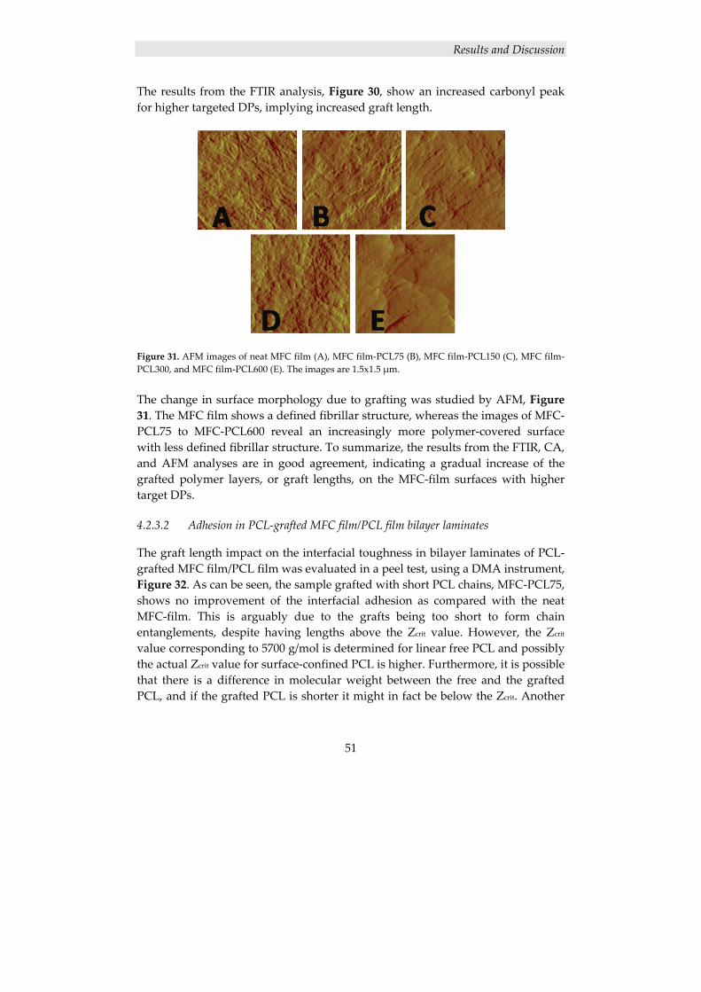
Results and Discussion
51
The results from the FTIR analysis, Figure 30, show an increased carbonyl peak for higher targeted DPs, implying increased graft length.
Figure 31. AFM images of neat MFC film (A), MFC film‐PCL75 (B), MFC film‐PCL150 (C), MFC film‐PCL300, and MFC film‐PCL600 (E). The images are 1.5x1.5 μm. The change in surface morphology due to grafting was studied by AFM, Figure 31. The MFC film shows a defined fibrillar structure, whereas the images of MFC‐PCL75 to MFC‐PCL600 reveal an increasingly more polymer‐covered surface with less defined fibrillar structure. To summarize, the results from the FTIR, CA, and AFM analyses are in good agreement, indicating a gradual increase of the grafted polymer layers, or graft lengths, on the MFC‐film surfaces with higher target DPs.
4.2.3.2 Adhesion in PCL‐grafted MFC film/PCL film bilayer laminates
The graft length impact on the interfacial toughness in bilayer laminates of PCL‐grafted MFC film/PCL film was evaluated in a peel test, using a DMA instrument, Figure 32. As can be seen, the sample grafted with short PCL chains, MFC‐PCL75, shows no improvement of the interfacial adhesion as compared with the neat MFC‐film. This is arguably due to the grafts being too short to form chain entanglements, despite having lengths above the Zcrit value. However, the Zcrit value corresponding to 5700 g/mol is determined for linear free PCL and possibly the actual Zcrit value for surface‐confined PCL is higher. Furthermore, it is possible that there is a difference in molecular weight between the free and the grafted PCL, and if the grafted PCL is shorter it might in fact be below the Zcrit. Another
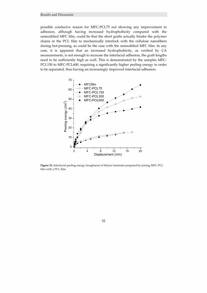
Results and Discussion
52
possible conducive reason for MFC‐PCL75 not showing any improvement in adhesion, although having increased hydrophobicity compared with the unmodified MFC film, could be that the short grafts actually hinder the polymer chains in the PCL film to mechanically interlock with the cellulose nanofibers during hot‐pressing, as could be the case with the unmodified MFC film. In any case, it is apparent that an increased hydrophobicity, as verified by CA measurements, is not enough to increase the interfacial adhesion, the graft lengths need to be sufficiently high as well. This is demonstrated by the samples MFC‐PCL150 to MFC‐PCL600, requiring a significantly higher peeling energy in order to be separated, thus having an increasingly improved interfacial adhesion.
Figure 32. Interfacial peeling energy (toughness) of bilayer laminates prepared by joining MFC‐PCL film with a PCL film.
Conclusions
53
5. CONCLUSIONS
The concept of using polymer/clay nanocomposites in coatings was evaluated for both thermally and UV‐curable coating systems. Thermally cured coatings were prepared from neat and nanofilled hyperbranched resins of Boltorn H30 and a polyol spacer, using HMMM as crosslinker, and the resulting films were smooth and transparent. According to XRD and TEM the nanofilled coatings had a mainly exfoliated structure, and DMA also rendered indications of a nano‐scale dispersion. Furthermore, the DMA showed a significant increase in the Tg, a slightly higher storage modulus – both above and below the Tg,‐ and indications of a more crosslinked network, for the clay‐containing film. TGA demonstrated the influence of the nanofiller on the thermal degradation in oxygen atmosphere. At 50% mass loss, the thermograms of the nanocomposites were shifted to approximately 40 °C higher temperature – an effect attributed to the improved barrier properties of the nanocomposites compared with the neat hyperbranched polymer. Visual inspection of the samples after TGA demonstrated the ability of the clay nanoparticles to preserve the shape of the samples even after almost complete decomposition, which could be useful in fire‐resistance applications. Conventional coating characterization methods demonstrated an increase in the surface hardness, scratch resistance and flexibility, with the introduction of clay, and all coatings exhibited excellent chemical resistance and adhesion. In order to yield a UV‐curable resin, the hydroxyl groups on Boltorn H30 was functionalized with acrylate groups using direct esterification with acrylic acid. Both 30% and 70% acrylated Boltorn H30 were synthesized successfully. However, when clay had been added before the acrylation, the outcome of the functionalization was affected, rendering an uneven acrylation. This in turn affected the coating properties, which was clearly demonstrated in the coating characterization. The nanocomposite preparation was successful both when clay was added before and after the acrylation – possibly with an indication that the addition of clay before the acrylation rendered a slightly higher degree of exfoliation – and as expected, a better dispersion of the nanoparticles was
Conclusions
54
obtained in the 30% acrylated matrix than in the 70% acrylated matrix. This would imply that the 30% acrylated Boltorn H30 with clay added before the acrylation would give the best coating. However, the uneven acrylation, caused by clay added before the acrylation, counteracted many of the positive effects of the nanoparticle addition. Consequently, it was the film made from 30% acrylated Boltorn H30 with clay added after the acrylation – which also had a very high degree of exfoliation – that exhibited the largest property improvements, compared with the corresponding film without nanofiller. These property improvements comprised a harder surface, better scratch resistance, better adhesion to metal substrates and also a small improvement in flexibility. PGMA was synthesized using ATRP, and subsequently a linear analogue to the hyperbranched Boltorn H30 was obtained by modification of the synthesized PGMA with Bis‐MPA. The resulting polymer was readily water‐soluble and therefore a suitable candidate for the comparative study of linear and hyperbranched polymers and their efficiency in nanocomposite preparation, using the solution intercalation method with water as solvent. Accordingly, nanocomposites were prepared from both the synthesized linear polymer, Bis‐MPA‐modified PGMA, and the hyperbranched polymer, Boltorn H30. Free‐standing crosslinked films were prepared from the nanocomposites and the dispersion of the clay layers was investigated with XRD and TEM; the XRD results, corroborated by the TEM analysis, display a mainly exfoliated structure in the hyperbranched polymer/clay nanocomposites, while the linear polymer/clay nanocomposites exhibited a mainly intercalated structure. These results strongly indicate that the hypothesis that hyperbranched polymers are superior to linear polymers, in their ability to promote and stabilize an exfoliated clay structure in this type of nanocomposite preparation, is valid. Thin films of hyperbranched polymer/cellulose nanocomposites were prepared by impregnating MFC nanopaper templates with Boltorn H30‐based matrix solutions, subsequently crosslinked to form networks. A strong increase in matrix Tg of up to 71 °C was observed for the nanocomposites containing up to 55% by volume of nanofibers. The reason for this is the decreased molecular mobility in the geometrically confined network, due to interactions with the cellulose nanofiber surfaces. Covalent matrix‐nanofiber linkages are present, suggesting a new nanocomposites concept where a significant proportion of the confined polymer matrix is covalently attached to the cellulose nanofibers, thus identifying cellulose nanopaper templates as a highly reactive reinforcement phase. This unique feature of cellulose nanopaper is in contrast with commonly used
Conclusions
55
composites reinforcements such as polyethylene fibers, aramide fibers, carbon fibers, and carbon nanotubes. In order to evaluate a route for increasing the compatibility between cellulose nanofibers and hydrophobic polymer matrices, MFC was grafted with PCL using ROP. FTIR and TGA analysis verified that the addition of different amounts of free initiator to the system results in various amounts of PCL grafted from the surface of MFC. Furthermore, TGA was used to estimate the composition of the samples; the amounts of PCL were calculated to 16, 19, and 21%, for MFC‐PCL300, MFCPCL600, and MFC‐PCL1200, respectively. In contrast to unmodified MFC, the MFC‐PCL was dispersible in nonpolar organic solvents. Cellulose nanofiber films of MFC were grafted with PCL via ROP, using addition of free initiator to control the polymerization in order to obtain different targeted DPs. Characterization of the ungrafted PCL and PCL‐grafted MFC films showed an increase in the molecular weight, and the graft layer thickness, with higher target DP. The PCL‐grafted MFC films were subsequently hot‐pressed with neat PCL films to form bilayer laminates. Peel‐tests of the bilayer laminates showed a gradual increase in the required delamination peeling energy with increased molecular weight of the PCL grafts, which demonstrates a significant impact of the graft length on the interfacial adhesion. Thus, the formation of entanglements across the immiscible cellulose/PCL interface promotes plastic shear yielding in the bulk polymer layer and therefore dramatically enhances interfacial toughness of the immiscible interface studied.
Future Work
56
6. FUTURE WORK
In order to further elucidate the effect of the dendritic structure on the exfoliation process in polymer/clay nanocomposite preparation, it would be interesting to compare the hyperbranched polymer Boltorn®, of different pseudo‐generations, with the corresponding dendrimers, i.e., monodisperse dendritic polymers with perfect branching. Does the polydispersity of Boltorn® play a role in the successful nanocomposite preparation with montmorillonite? The rheological properties of a material are greatly affected by the introduction of a nanosized filler. Therefore, an extensive rheological study of the materials presented in this thesis would render valuable information. Further understanding of the rheological properties is also very important – essential, in fact – if the nanocomposites are to be used in industrial coating applications. Furthermore, it would be very interesting to explore the possibility of using cellulose nanofibers, e.g., MFC or MCC, as reinforcement in coating applications. In addition to having potential for improving material properties, such as mechanical properties and thermal stability, while maintaining transparency, the “green” nature of cellulose nanoparticles is also a desired feature in many applications. Another interesting possibility is to combine clay and cellulose nanofibers in polymer nanocomposites – a combination from which numerous synergy effects could be envisioned. For example, the introduction of clay nanoparticles to a polymer/cellulose nanocomposite is hypothesized to increase the thermal stability and fire‐resistance of the material.
Acknowledgements
57
7. ACKNOWLEDGEMENTS
First of all I would like to express my sincere gratitude to my supervisors Prof. Anders Hult for accepting me as a PhD student, for knowing so much about many things and for always having great visions, and Prof. Eva Malmström for your invaluable support over the years, for always taking the time for me and for always inspiring me to do better. Prof. Mats Johansson is thanked for helpful discussions and for always finding time to answer questions.
All seniors at the department of Fiber and Polymer Technology are thanked for their help and hard work and for creating an inspiring and creative atmosphere to work in. All members of the administrative and technical staff are thanked for their help and for keeping the place running. Especially Inger and Karin B are thanked for helping me with the all‐important paperwork and computer‐related issues, Maggan, Inga and Brita for always answering my questions and Ove and Bosse for always fixing whatever needs to be fixed.
Dr. Lars Eriksson at SU is thanked for valuable discussions regarding XRD and Sonny Jönsson for valuable discussions regarding photochemistry. Masanori Mori at FEI is thanked for all the help with the TEM.
Wilhelm Becker Jubileumsfond, The Swedish Research Council and the Wallenberg Wood Science Center are gratefully acknowledged for financial support.
My coauthors are all thanked for good collaboration, especially Marielle for being so reliable and caring and Lars B for always having good ideas.
All former and present PhD students at the department are thanked for making this such a nice and friendly place to work at. I would especially like to thank Karin O for being my “friend on the other side”, Anders B for introducing me to the challenging world of TEM, my dear latino bunch – Eugenia, Idoia, Ana, Alessandro, Marie, Fran, Natalia, Kamyar, Victoria – for all the fun and for including me, Maria and Sara B for your friendship, Richard for being the most “nutty professor” I know, Anna S for being my coworker on what could have been a really nice project, Jonas H for bringing some Mumin‐feeling, Anders Hö for the nice chats, Jonas E for being all about safety, David for being almost Swedish, Thomas for bringing some order to the UWG group, Sung‐Woo for your help with TGA and hot‐pressing, Roland for introducing me to fire‐resistance characterization, Kotte for all the nice chats, Lars‐Erik for helpful discussions regarding DLS, Rikard for all the discussions, Simon for being the chick‐magnet, Magnus and Per for helping me deal with the printing office, and of course all my other friends on all four floors on “the other side” – none of you are forgotten!
To all former and present members of “Ytgruppen”, my home away from home: thank you for creating such a fun, creative and family‐like atmosphere – a great place to work at! A special thanks goes to my former and present roomies: Anna C for returning to the group and for being a great friend, Johan for being helpful in the lab and for teaching me about music, Danne for being sometimes confusing but always full of ideas, Camilla for all the nice chats and for
Acknowledgements
58
“Camilla‐mat”, Linn for your invaluable help during these last weeks and for our un‐mentionable discussions, Kim for your relaxed and caring personality, and to Hanna, my constant travel‐roomie, for your friendship and all the fun we have had, both at home and abroad. Great thanks also to Fina for 16 years of friendship and working together most of them – no wonder we understand each other so well ☺, Emma Ö for your friendship and for always being up for anything, lill‐Robban for always helping me when I need it, for being so generous and for your weird sense of humor, Hasse for being a great diploma work supervisor, Peter for being amusingly confusing, Michael for the help in the lab and for the chicken wings, stor‐Robban for being annoying on the outside but nice on the inside, Ci for bringing another perspective, Geraldine for trying to explain cyclic voltammetry, Daniel S for the singing and dancing, Tommy for your unexpected return, Andreas for your appreciated efforts on bringing some order to the lab, Kattis for being my lab‐neighbor and fellow coating maker, Jarmo for bringing some sisu to the group, George for the Greek lessons, Neil for being so funny and for the guitar‐playing at Lucia, Magnus J for being the best at getting the ducknose, Pelle for the good old times, Pontus for being the fixer and for your will to sing, Petra for being so genuinely nice, Sara K for your flying visits, Stacy for being so helpful and easy‐going, Maribel for being the hottest Lucia ever at FPT, Yvonne for being a true enthusiast, Susanne for all your help and for being the new, sweet “projlabs‐bitch”, Lina for the fun while it lasted, Marie for proving that French people can learn to speak Swedish really fast, Mauro for proving that even the worst sugar addict can quit, Alireza for being Alibubbu, the webmaster, Ting for being the quirky onion, Niklas for being kind enough to give me your thumbs, Hui for being an excited cheese lover, Sara O for your smiling visits, Markus W for defending me and for living on the right side of Stockholm, Christian for talking even faster than me, Emma L for your strange fruit‐eating habits, and Carl for sharing the results of your interest for food with the rest of us. All diploma workers and project students visiting the group throughout the years are thanked for contributing to the atmosphere and for all the fun times. Some almost‐members of “Ytgruppen” are thanked: Magnus E for your friendship and for all our, more or less serious, discussions, Axel for making “snyltning” into an art form, and Helena and Martin for your flying visits.
Markus H is gratefully acknowledged for your help with the ChemDraw structures. My graphics consultants, my cousin Peter and my sister Eva, are thanked for helping me with troublesome pictures and file formats.
Jag vill också tacka min släkt, min utökade familj och alla mina många fantastiska vänner utanför KTH för er vänskap och ert stora stöd. Ni är jätteviktiga för mig och jag har absolut inte glömt bort er, trots att jag ibland har varit ganska inne i min jobb‐bubbla, särskilt den sista tiden under avhandlingsskrivandet. Tack för att ni inte har glömt bort mig heller!
Tack till familjen Lundquist, Peter, Ingrid och Olle, för att ni med öppna armar har välkomnat mig i familjen och för att ni alltid ställer upp och hjälper till med barnpassning, eller vad det än må vara.
Till min familj: tack mamma och pappa för er ovillkorliga kärlek och generositet, för att ni alltid stöttat och trott på mig och för att ni alltid satt mig och Eva i första hand. Särskilt tack för all hjälp under den senaste tiden – utan er hade pusslet inte gått ihop. Tack till min kära syster Eva för att du alltid ställer upp och hjälper mig med bilder och grafikrelaterade frågor och till Alex för att du är en sådan toppenkille och för att du är så stark ☺.
Slutligen ett stort tack till min egen lilla familj: Mats för all kärlek och trygghet du givit mig under mer än halva mitt liv och för att du givit mig det bästa av allt – Elvira, min ”myschis”. Älskar er alltid!
References
59
8. REFERENCES
(1) Plummer, C. J. G.; Garamszegi, L.; Leterrier, Y.; Rodlert, M.; Månson, J.‐A. E. Hyperbranched Polymer Layered Silicate Nanocomposites Chemistry of Materials 2002, 14, 486‐488.
(2) Hull, D.; Clyne, T. W.; Editors, An Introduction to Composite Materials, 2nd Edition. 1996; p 326 pp.
(3) Chen, T. K.; Tien, Y. I.; Wei, K. H. Synthesis and characterization of novel segmented polyurethane/clay nanocomposite via poly(e‐caprolactone)/clay Journal of Polymer Science, Part A: Polymer Chemistry 1999, 37, 2225‐2233.
(4) Alexandre, M.; Dubois, P. Polymer‐layered silicate nanocomposites: preparation, properties and uses of a new class of materials Materials Science & Engineering, R: Reports 2000, R28, 1‐63.
(5) Okada, A.; Kawasumi, M.; Kurauchi, T.; Kamigaito, O. Synthesis and characterization of a nylon 6‐clay hybrid Polymer Preprints (American Chemical Society, Division of Polymer Chemistry) 1987, 28, 447‐448.
(6) Usuki, A.; Kojima, Y.; Kawasumi, M.; Okada, A.; Fukushima, Y.; Kurauchi, T.; Kamigaito, O. Synthesis of nylon 6‐clay hybrid Journal of Materials Research 1993, 8, 1179‐1184.
(7) Ray, S. S.; Okamoto, M. Polymer/layered silicate nanocomposites: a review from preparation to processing Progress in Polymer Science 2003, 28, 1539‐1641.
(8) Le Forestier, L.; Muller, F.; Villieras, F.; Pelletier, M. Textural and hydration properties of a synthetic montmorillonite compared with a natural Na‐exchanged clay analogue Applied Clay Science 2010, 48, 18‐25.
(9) Akelah, A.; Salahuddin, N.; Hiltner, A.; Baer, E.; Moet, A. Morphological hierarchy of butadiene‐acrylonitrile/montmorillonite nanocomposite Nanostructured Materials 1994, 4, 965‐978.
(10) LeBaron, P. C.; Wang, Z.; Pinnavaia, T. J. Polymer‐layered silicate nanocomposites: an overview Applied Clay Science 1999, 15, 11‐29.
(11) Tjong, S. C. Structural and mechanical properties of polymer nanocomposites Materials Science & Engineering, R: Reports 2006, R53, 73‐197.
(12) Wang, Z.; Pinnavaia, T. J. Nanolayer Reinforcement of Elastomeric Polyurethane Chemistry of Materials 1998, 10, 3769‐3771.
(13) Kojima, Y.; Usuki, A.; Kawasumi, M.; Okada, A.; Kurauchi, T.; Kamigaito, O. Synthesis of nylon 6‐clay hybrid by montmorillonite intercalated with e‐caprolactam Journal of Polymer Science, Part A: Polymer Chemistry 1993, 31, 983‐986.
(14) Messersmith, P. B.; Giannelis, E. P. Polymer‐layered silicate nanocomposites: in situ intercalative polymerization of ε‐caprolactone in layered silicates Chemistry of Materials 1993, 5, 1064‐1066.
(15) Moet, A. S.; Akelah, A. Polymer‐clay nanocomposites: polystyrene grafted onto montmorillonite interlayers Materials Letters 1993, 18, 97‐102.
(16) Mariani, A.; Bidali, S.; Caria, G.; Monticelli, O.; Russo, S.; Kenny, J. M. Synthesis and characterization of epoxy resin‐montmorillonite nanocomposites obtained by frontal polymerization Journal of Polymer Science, Part A: Polymer Chemistry 2007, 45, 2204‐2211.
(17) Giannelis, E. P. Polymer layered silicate nanocomposites Advanced Materials 1996, 8, 29‐35.
References
60
(18) Vaia, R. A.; Vasudevan, S.; Krawiec, W.; Scanlon, L. G.; Giannelis, E. P. New polymer electrolyte nanocomposites. Melt intercalation of poly(ethylene oxide) in mica‐type silicates Advanced Materials 1995, 7, 154‐156.
(19) Kawasumi, M.; Hasegawa, N.; Kato, M.; Usuki, A.; Okada, A. Preparation and Mechanical Properties of Polypropylene‐Clay Hybrids Macromolecules 1997, 30, 6333‐6338.
(20) Zilg, C.; Muelhaupt, R.; Finter, J. Morphology and toughness/stiffness balance of nanocomposites based upon anhydride‐cured epoxy resins and layered silicates Macromolecular Chemistry and Physics 1999, 200, 661‐670.
(21) Lagaly, G. Introduction: from clay mineral‐polymer interactions to clay mineral‐polymer nanocomposites Applied Clay Science 1999, 15, 1‐9.
(22) Carretero‐Gonzalez, J.; Retsos, H.; Giannelis, E. P.; Ezquerra, T. A.; Hernandez, M.; Lopez‐Manchado, M. A. Miscibility‐dispersion, interfacial strength and nanoclay mobility relationships in polymer nanocomposites Soft Matter 2009, 5, 3481‐3486.
(23) Torre, L.; Chieruzzi, M.; Kenny, J. M. Compatibilization and development of layered silicate nanocomposites based of unsatured polyester resin and customized intercalation agent Journal of Applied Polymer Science 2010, 115, 3659‐3666.
(24) Wu, J.; Lerner, M. M. Structural, thermal, and electrical characterization of layered nanocomposites derived from sodium‐montmorillonite and polyethers Chemistry of Materials 1993, 5, 835‐838.
(25) Ogata, N.; Kawakage, S.; Ogihara, T. Poly(vinyl alcohol)‐clay and poly(ethylene oxide)‐clay blends prepared using water as solvent Journal of Applied Polymer Science 1997, 66, 573‐581.
(26) Zanetti, M.; Lomakin, S.; Camino, G. Polymer layered silicate nanocomposites Macromolecular Materials and Engineering 2000, 279, 1‐9.
(27) Okada, A.; Kawasumi, M.; Usuki, A.; Kojima, Y.; Kurauchi, T.; Kamigaito, O. Nylon 6‐clay hybrid Materials Research Society Symposium Proceedings 1990, 171, 45‐50.
(28) Yano, K.; Usuki, A.; Okada, A.; Kurauchi, T.; Kamigaito, O. Synthesis and properties of polyimide‐clay hybrid Journal of Polymer Science, Part A: Polymer Chemistry 1993, 31, 2493‐2498.
(29) Giannelis, E. P.; Krishnamoorti, R.; Manias, E. Polymer‐silicate nanocomposites: model systems for confined polymers and polymer brushes Advances in Polymer Science 1999, 138, 107‐147.
(30) Vaia, R. A.; Price, G.; Ruth, P. N.; Nguyen, H. T.; Lichtenhan, J. Polymer/layered silicate nanocomposites as high performance ablative materials Applied Clay Science 1999, 15, 67‐92.
(31) Kornmann, X.; Thomann, R.; Mulhaupt, R.; Finter, J.; Berglund, L. A. High performance epoxy‐layered silicate nanocomposites Polymer Engineering and Science 2002, 42, 1815‐1826.
(32) Lee, H.‐s.; Fasulo, P. D.; Rodgers, W. R.; Paul, D. R. TPO based nanocomposites. Part 1. Morphology and mechanical properties Polymer 2005, 46, 11673‐11689.
(33) Pavlidou, S.; Papaspyrides, C. D. A review on polymer‐layered silicate nanocomposites Progress in Polymer Science 2008, 33, 1119‐1198.
(34) Kojima, Y.; Usuki, A.; Kawasumi, M.; Okada, A.; Kurauchi, T.; Kamigaito, O. Sorption of water in nylon 6‐clay hybrid Journal of Applied Polymer Science 1993, 49, 1259‐1264.
(35) Lan, T.; Pinnavaia, T. J. Clay‐Reinforced Epoxy Nanocomposites Chemistry of Materials 1994, 6, 2216‐2219.
(36) Messersmith, P. B.; Giannelis, E. P. Synthesis and barrier properties of poly(e‐caprolactone)‐layered silicate nanocomposites Journal of Polymer Science, Part A: Polymer Chemistry 1995, 33, 1047‐1057.
(37) Bharadwaj, R. K. Modeling the Barrier Properties of Polymer‐Layered Silicate Nanocomposites Macromolecules 2001, 34, 9189‐9192.
(38) Kim, S. H.; Kim, S. C. Synthesis and properties of polyethylene terephthalate/clay nanocomposites by in situ polymerization Journal of Applied Polymer Science 2007, 103, 1262‐1271.
References
61
(39) Blumstein, A. Polymerization of adsorbed monolayers. II. Thermal degradation of the inserted polymer Journal of Polymer Science, Part A: General Papers 1965, 3, 2665‐2672.
(40) Burnside, S. D.; Giannelis, E. P. Synthesis and properties of new poly(dimethylsiloxane) nanocomposites Chemistry of Materials 1995, 7, 1597‐1600.
(41) Gilman, J. W.; Kashiwagi, T.; Lichtenhan, J. D. Nanocomposites: a revolutionary new flame retardant approach SAMPE Journal 1997, 33, 40‐46.
(42) Lee, J.; Giannelis, E. P. Synthesis and characterization of unsaturated polyester and phenolic resin nanocomposites Polymer Preprints (American Chemical Society, Division of Polymer Chemistry) 1997, 38, 688‐689.
(43) Gilman, J. W. Flammability and thermal stability studies of polymer layered‐silicate (clay) nanocomposites Applied Clay Science 1999, 15, 31‐49.
(44) Yoon, P. J.; Fornes, T. D.; Paul, D. R. Thermal expansion behavior of nylon 6 nanocomposites Polymer 2002, 43, 6727‐6741.
(45) Dietsche, F.; Thomann, Y.; Thomann, R.; Mulhaupt, R. Translucent acrylic nanocomposites containing anisotropic laminated nanoparticles derived from intercalated layered silicates Journal of Applied Polymer Science 2000, 75, 396‐405.
(46) Strawhecker, K. E.; Manias, E. Structure and Properties of Poly(vinyl alcohol)/Na+ Montmorillonite Nanocomposites Chemistry of Materials 2000, 12, 2943‐2949.
(47) Fogelström, L.; Malmström, E.; Mats, J.; Hult, A. Hard and Flexible Nanocomposite Coatings using Nanoclay‐filled Hyperbranched Polymers Submitted to ACS Applied Materials & Interfaces 2010
(48) Ahmadi, S. J.; Huang, Y. D.; Li, W. Synthetic routes, properties and future applications of polymer‐layered silicate nanocomposites Journal of Materials Science 2004, 39, 1919‐1925.
(49) Kawasumi, M. The discovery of polymer‐clay hybridsJournal of Polymer Science, Part A: Polymer Chemistry 2004, 42, 819‐824.
(50) Hult, A.; Johansson, M.; Malmström, E. Hyperbranched polymers Advances in Polymer Science 1999, 143, 1‐34.
(51) Voit, B. I. Dendritic polymers: from aesthetic macromolecules to commercially interesting materials Acta Polymerica 1995, 46, 87‐99.
(52) Carlmark, A.; Hawker, C.; Hult, A.; Malkoch, M. New methodologies in the construction of dendritic materials Chemical Society Reviews 2009, 38, 352‐362.
(53) Flory, P. J. Molecular size distribution in three‐dimensional polymers. VI. Branched polymer containing A‐R‐Bf‐1‐type units Journal of the American Chemical Society 1952, 74, 2718‐2723.
(54) Kim, Y. H.; Webster, O. W. Water soluble hyperbranched polyphenylene: ʺa unimolecular micelle?ʺ Journal of the American Chemical Society 1990, 112, 4592‐4593.
(55) Gao, C.; Yan, D. Hyperbranched polymers: from synthesis to applications Progress in Polymer Science 2004, 29, 183‐275.
(56) Voit, B. Hyperbranched polymers‐all problems solved after 15 years of research? Journal of Polymer Science, Part A: Polymer Chemistry 2005, 43, 2679‐2699.
(57) Buhleier, E.; Wehner, W.; Vögtle, F. ʺCascadeʺ‐ and ʺnonskid‐chain‐likeʺ syntheses of molecular cavity topologies Synthesis 1978, 155‐158.
(58) Denkewalter, R. G.; Kolc, J.; Lukasavage, W. J. Macromolecular highly branched homogeneous compound based on lysine units U.S. patent 1981, 79‐27622, 4289872.
(59) Tomalia, D. A.; Baker, H.; Dewald, J.; Hall, M.; Kallos, G.; Martin, S.; Roeck, J.; Ryder, J.; Smith, P. A new class of polymers: starburst‐dendritic macromolecules Polymer Journal 1985, 17, 117‐132.
(60) Newkome, G. R.; Yao, Z.; Baker, G. R.; Gupta, V. K. Micelles. Part 1. Cascade molecules: a new approach to micelles. A [27]‐arborol Journal of Organic Chemistry 1985, 50, 2003‐2004.
References
62
(61) Van Benthem, R. A. T. M.; Muscat, D.; Stanssens, D. A. W. New commercially available hyperbranched polymers ‐ for tailor made solutions Polymeric Materials Science and Engineering 1999, 80, 72‐73.
(62) Malmström, E.; Johansson, M.; Hult, A. Hyperbranched Aliphatic Polyesters Macromolecules 1995, 28, 1698‐1703.
(63) Shi, Z.; Zhou, Y.; Yan, D. Facile fabrication of pH‐responsive and size‐controllable polymer vesicles from a commercially available hyperbranched polyester Macromolecular Rapid Communications 2008, 29, 412‐418.
(64) Froehling, P.; Brackman, J. Properties and applications of poly(propylene imine) dendrimers and poly(esteramide) hyperbranched polymers Macromolecular Symposia 2000, 151, 581‐589.
(65) Yates, C. R.; Hayes, W. Synthesis and applications of hyperbranched polymers European Polymer Journal 2004, 40, 1257‐1281.
(66) Hult, A.; Johansson, M.; Malmström, E. Dendritic resins for coating applications Macromolecular Symposia 1995, 98, 1159‐1161.
(67) Magnusson, H.; Malmström, E.; Hult, A.; Johansson, M. The effect of degree of branching on the rheological and thermal properties of hyperbranched aliphatic polyethers Polymer 2001, 43, 301‐306.
(68) Percec, V.; Chu, P.; Kawasumi, M. Toward ʺWillowlikeʺ Thermotropic Dendrimers Macromolecules 1994, 27, 4441‐4453.
(69) Marcos, M.; Martin‐Rapun, R.; Omenat, A.; Serrano, J. L. Highly congested liquid crystal structures: dendrimers, dendrons, dendronized and hyperbranched polymers Chemical Society Reviews 2007, 36, 1889‐1901.
(70) Fogelström, L.; Antoni, P.; Malmström, E.; Hult, A. UV‐curable hyperbranched nanocomposite coatings Progress in Organic Coatings 2006, 55, 284‐290.
(71) Johansson, M.; Malmström, E.; Jansson, A.; Hult, A. Novel concept for low temperature curing powder coatings based on hyperbranched polyesters Journal of Coatings Technology 2000, 72, 49‐54.
(72) Pettersson, B., Properties and Applications of Dendritic polymers. Perstorp Specialty Chemicals AB: Perstorp, Sweden, 2001.
(73) Zagar, E.; Zigon, M.; Podzimek, S. Characterization of commercial aliphatic hyperbranched polyesters Polymer 2006, 47, 166‐175.
(74) Shen, Z.; Simon, G. P.; Cheng, Y.‐B. Comparison of solution intercalation and melt intercalation of polymer‐clay nanocomposites Polymer 2002, 43, 4251‐4260.
(75) Chen, B.; Evans, J. R. G. Preferential intercalation in polymer‐clay nanocomposites Journal of Physical Chemistry B 2004, 108, 14986‐14990.
(76) Rodlert, M.; Plummer, C. J. G.; Garamszegi, L.; Leterrier, Y.; Grunbauer, H. J. M.; Månson, J.‐A. E. Hyperbranched polymer/montmorillonite clay nanocomposites Polymer 2004, 45, 949‐960.
(77) Rodlert, M.; Plummer, C. J. G.; Leterrier, Y.; Månson, J.‐A. E.; Grunbauer, H. J. M. Rheological behavior of hyperbranched polymer/montmorillonite clay nanocomposites Journal of Rheology 2004, 48, 1049‐1065.
(78) Eichhorn, S. J.; Dufresne, A.; Aranguren, M.; Marcovich, N. E.; Capadona, J. R.; Rowan, S. J.; Weder, C.; Thielemans, W.; Toman, M.; Renneckar, S.; Gindl, W.; Veigel, S.; Keckes, J.; Yano, H.; Abe, K.; Nogi, M.; Nakagaito, A. N.; Mangalam, A.; Simonsen, J.; Benight, A. S.; Bismarck, A.; Berglund, L. A.; Peijs, T. Review: current international research into cellulose nanofibres and nanocomposites Journal of Materials Science 2010, 45, 1‐33.
(79) Sakurada, I.; Nukushina, Y.; Ito, T. Experimental determination of the elastic modulus of crystalline regions in oriented polymers Journal of Polymer Science 1962, 57, 651‐660.
(80) Hubbe, M. A.; Rojas, O. J.; Lucia, L. A.; Sain, M. Cellulosic nanocomposites: a review Bioresources 2008, 3, 929‐980.
References
63
(81) Turbak, A. F.; Snyder, F. W.; Sandberg, K. R. Microfibrillated cellulose, a new cellulose product: properties, uses, and commercial potential Journal of Applied Polymer Science: Applied Polymer Symposium 1983, 37, 815‐827.
(82) Herrick, F. W.; Casebier, R. L.; Hamilton, J. K.; Sandberg, K. R. Microfibrillated cellulose: morphology and accessibility Journal of Applied Polymer Science: Applied Polymer Symposium 1983, 37, 797‐813.
(83) Paakko, M.; Ankerfors, M.; Kosonen, H.; Nykanen, A.; Ahola, S.; Osterberg, M.; Ruokolainen, J.; Laine, J.; Larsson, P. T.; Ikkala, O.; Lindstrom, T. Enzymatic hydrolysis combined with mechanical shearing and high‐pressure homogenization for nanoscale cellulose fibrils and strong gels Biomacromolecules 2007, 8, 1934‐1941.
(84) Wågberg, L.; Decher, G.; Norgren, M.; Lindström, T.; Ankerfors, M.; Axnäs, K. The build‐up of polyelectrolyte multilayers of microfibrillated cellulose and cationic polyelectrolytes Langmuir 2008, 24, 784‐795.
(85) Henriksson, M.; Henriksson, G.; Berglund, L. A.; Lindström, T. An environmentally friendly method for enzyme‐assisted preparation of microfibrillated cellulose (MFC) nanofibers European Polymer Journal 2007, 43, 3434‐3441.
(86) Henriksson, M.; Berglund, L. A.; Isaksson, P.; Lindström, T.; Nishino, T. Cellulose Nanopaper Structures of High Toughness Biomacromolecules 2008, 9, 1579‐1585.
(87) Samir, M. A. S. A.; Alloin, F.; Dufresne, A. Review of Recent Research into Cellulosic Whiskers, Their Properties and Their Application in Nanocomposite Field Biomacromolecules 2005, 6, 612‐626.
(88) Berglund, L. Cellulose‐based nanocomposites Natural Fibers, Biopolymers, and Biocomposites 2005, 807‐832.
(89) Favier, V.; Canova, G. R.; Cavaille, J. Y.; Chanzy, H.; Dufreshne, A.; Gauthier, C. Nanocomposite materials from latex and cellulose whiskers Polymers for Advanced Technologies 1995, 6, 351‐355.
(90) Yano, H.; Sugiyama, J.; Nakagaito, A. N.; Nogi, M.; Matsuura, T.; Hikita, M.; Handa, K. Optically transparent composites reinforced with networks of bacterial nanofibers Advanced Materials 2005, 17, 153‐155.
(91) Shimazaki, Y.; Miyazaki, Y.; Takezawa, Y.; Nogi, M.; Abe, K.; Ifuku, S.; Yano, H. Excellent Thermal Conductivity of Transparent Cellulose Nanofiber/Epoxy Resin Nanocomposites Biomacromolecules 2007, 8, 2976‐2978.
(92) Iwamoto, S.; Nakagaito, A. N.; Yano, H.; Nogi, M. Optically transparent composites reinforced with plant fiber‐based nanofibers Applied Physics A: Materials Science & Processing 2005, 81, 1109‐1112.
(93) John, M. J.; Anandjiwala, R. D. Recent developments in chemical modification and characterization of natural fiber‐reinforced composites Polymer Composites 2008, 29, 187‐207.
(94) Bledzki, A. K.; Reihmane, S.; Gassan, J. Thermoplastics reinforced with wood fillers: a literature review Polymer‐Plastics Technology and Engineering 1998, 37, 451‐468.
(95) Bledzki, A. K.; Gassan, J. Composites reinforced with cellulose based fibres Progress in Polymer Science 1999, 24, 221‐274.
(96) Brumer, H., III; Zhou, Q.; Baumann, M. J.; Carlsson, K.; Teeri, T. T. Activation of Crystalline Cellulose Surfaces through the Chemoenzymatic Modification of Xyloglucan Journal of the American Chemical Society 2004, 126, 5715‐5721.
(97) Schwab, E.; Stannett, V.; Hermans, J. J. Grafting onto cellulose and cellulose fibers Tappi 1961, 44, 251‐256.
(98) Kaizerman, S.; Mino, G.; Melnhold, L. F. The polymerization of vinyl monomers in cellulosic fibers Textile Research Journal 1962, 32, 136‐140.
References
64
(99) Carlmark, A.; Malmström, E. Atom Transfer Radical Polymerization from Cellulose Fibers at Ambient Temperature Journal of the American Chemical Society 2002, 124, 900‐901.
(100) Lindqvist, J.; Malmström, E. Surface modification of natural substrates by atom transfer radical polymerization Journal of Applied Polymer Science 2006, 100, 4155‐4162.
(101) Plackett, D.; Jankova, K.; Egsgaard, H.; Hvilsted, S. Modification of Jute Fibers with Polystyrene via Atom Transfer Radical Polymerization Biomacromolecules 2005, 6, 2474‐2484.
(102) Takolpuckdee, P.; Westwood, J.; Lewis, D. M.; Perrier, S. Polymer architectures via reversible addition fragmentation chain transfer (RAFT) polymerization Macromolecular Symposia 2004, 216, 23‐35.
(103) Roy, D.; Guthrie, J. T.; Perrier, S. Graft Polymerization: Grafting Poly(styrene) from Cellulose via Reversible Addition‐Fragmentation Chain Transfer (RAFT) Polymerization Macromolecules 2005, 38, 10363‐10372.
(104) Barsbay, M.; Gueven, O.; Stenzel, M. H.; Davis, T. P.; Barner‐Kowollik, C.; Barner, L. Verification of Controlled Grafting of Styrene from Cellulose via Radiation‐Induced RAFT Polymerization Macromolecules 2007, 40, 7140‐7147.
(105) Hadano, S.; Onimura, K.; Tsutsumi, H.; Yamasaki, H.; Oishi, T. Syntheses of chemical‐modified cellulose obtained from waste pulp Journal of Applied Polymer Science 2003, 90, 2059‐2065.
(106) Hafren, J.; Cordova, A. Direct organocatalytic polymerization from cellulose fibers Macromolecular Rapid Communications 2005, 26, 82‐86.
(107) Lönnberg, H.; Zhou, Q.; Brumer, H., III; Teeri, T.; Malmström, E.; Hult, A. Grafting of Cellulose Fibers with Poly(ε ‐caprolactone) and Poly(L‐lactic acid) via Ring‐Opening Polymerization Biomacromolecules 2006, 7, 2178‐2185.
(108) Hawker, C. J.; Bosman, A. W.; Harth, E. New Polymer Synthesis by Nitroxide Mediated Living Radical Polymerizations Chemical Reviews 2001, 101, 3661‐3688.
(109) Matyjaszewski, K.; Xia, J. Atom Transfer Radical Polymerization Chemical Reviews 2001, 101, 2921‐2990.
(110) Barner, L.; Quinn, J. F.; Barner‐Kowollik, C.; Vana, P.; Davis, T. P. Reversible addition‐fragmentation chain transfer polymerization initiated with gamma‐radiation at ambient temperature: an overview European Polymer Journal 2003, 39, 449‐459.
(111) Wang, J.‐S.; Matyjaszewski, K. Controlled/ʺlivingʺ radical polymerization. atom transfer radical polymerization in the presence of transition‐metal complexes Journal of the American Chemical Society 1995, 117, 5614‐5615.
(112) Wang, J.‐S.; Matyjaszewski, K. Controlled/ʺLivingʺ Radical Polymerization. Halogen Atom Transfer Radical Polymerization Promoted by a Cu(I)/Cu(II) Redox Process Macromolecules 1995, 28, 7901‐7910.
(113) Kato, M.; Kamigaito, M.; Sawamoto, M.; Higashimura, T. Polymerization of Methyl Methacrylate with the Carbon Tetrachloride/Dichlorotris‐ (triphenylphosphine)ruthenium(II)/Methylaluminum Bis(2,6‐di‐tert‐butylphenoxide) Initiating System: Possibility of Living Radical Polymerization Macromolecules 1995, 28, 1721‐1723.
(114) Carothers, W. H.; Dorough, G. L.; Van Natta, F. J. Polymerization and ring formation. X. Reversible polymerization of six‐membered cyclic esters Journal of the American Chemical Society 1932, 54, 761‐772.
(115) Penczek, S.; Cypryk, M.; Duda, A.; Kubisa, P.; Slomkowski, S. Living ring‐opening polymerizations of heterocyclic monomers Progress in Polymer Science 2007, 32, 247‐282.
(116) Albertsson, A. C.; Editor, Degradable Aliphatic Polyesters Advances in Polymer Science Volume 157 2002, 179 pp.
(117) Goldschmidt, A., BASF Handbook on Basics of Coating Technology. BASF Coatings AG: Münster, Germany, 2003.
References
65
(118) Hare, C. H., Protective Coatings. SSPC:the Society for Protective Coatings: Pittsburgh, PA, USA, 1994.
(119) Bentley, J.; Turner, G. P. A., Introduction to Paint Chemistry and Principles of Paint Technology. 4th ed.; Chapman & Hall: London, UK, 1998.
(120) Marrion, A. R., The Chemistry and Physics of Coatings. The Royal Society of Chemistry: Cambridge, UK, 1994.
(121) Wicks, Z. W., JR; Jones, F. N.; Pappas, P. S.; Wicks, D. A., Organic Coatings. 3rd ed.; John Wiley & Sons, Inc.: Hoboken, NJ, USA, 2007.
(122) van Benthem, R. A. T. M. Novel hyperbranched resins for coating applications Progress in Organic Coatings 2000, 40, 203‐214.
(123) Wang, Z.; Han, E.; Ke, W. Effect of nanoparticles on the improvement in fire‐resistant and anti‐ageing properties of flame‐retardant coating Surface and Coatings Technology 2006, 200, 5706‐5716.
(124) Johansson, M.; Glauser, T.; Jansson, A.; Hult, A.; Malmström, E.; Claesson, H. Design of coating resins by changing the macromolecular architecture: solid and liquid coating systems Progress in Organic Coatings 2003, 48, 194‐200.
(125) Zagar, E.; Huskic, M.; Grdadolnik, J.; Zigon, M.; Zupancic‐Valant, A. Effect of Annealing on the Rheological and Thermal Properties of Aliphatic Hyperbranched Polyester Based on 2,2‐Bis(methylol)propionic Acid Macromolecules 2005, 38, 3933‐3942.
(126) Zagar, E.; Huskic, M.; Zigon, M. Structure‐to‐properties relationship of aliphatic hyperbranched polyesters Macromolecular Chemistry and Physics 2007, 208, 1379‐1387.
(127) Claesson, H.; Scheurer, C.; Malmström, E.; Johansson, M.; Hult, A.; Paulus, W.; Schwalm, R. Semi‐crystalline thermoset resins: tailoring rheological properties in melt using comb structures with crystalline grafts Progress in Organic Coatings 2004, 49, 13‐22.
(128) Lönnberg, H.; Fogelström, L.; Berglund, L.; Malmström, E.; Hult, A. Surface grafting of microfibrillated cellulose with poly(e‐caprolactone) ‐ Synthesis and characterization European Polymer Journal 2008, 44, 2991‐2997.
(129) Hedenqvist, M. S.; Yousefi, H.; Malmström, E.; Johansson, M.; Hult, A.; Gedde, U. W.; Trollsås, M.; Hedrick, J. L. Transport properties of hyperbranched and dendrimer‐like star polymers Polymer 1999, 41, 1827‐1840.
(130) Paul, D. R.; Robeson, L. M. Polymer nanotechnology: Nanocomposites Polymer 2008, 49, 3187‐3204.
(131) Save, M.; Weaver, J. V. M.; Armes, S. P.; McKenna, P. Atom Transfer Radical Polymerization of Hydroxy‐Functional Methacrylates at Ambient Temperature: Comparison of Glycerol Monomethacrylate with 2‐Hydroxypropyl Methacrylate Macromolecules 2002, 35, 1152‐1159.
(132) Nakagaito, A. N.; Yano, H. Novel high‐strength biocomposites based on microfibrillated cellulose having nano‐order‐unit web‐like network structure Applied Physics A: Materials Science & Processing 2004, 80, 155‐159.
(133) Henriksson, M.; Berglund, L. A. Structure and properties of cellulose nanocomposite films containing melamine formaldehyde Journal of Applied Polymer Science 2007, 106, 2817‐2824.
(134) Tsagaropoulos, G.; Eisenberg, A. Dynamic Mechanical Study of the Factors Affecting the Two Glass Transition Behavior of Filled Polymers. Similarities and Differences with Random Ionomers Macromolecules 1995, 28, 6067‐6077.
(135) Van de Velde, K.; Kiekens, P. Biopolymers: overview of several properties and consequences on their applications Polymer Testing 2002, 21, 433‐442.
(136) Riedel, U.; Nickel, J. Natural fibre‐reinforced biopolymers as construction materials. New discoveries Angewandte Makromolekulare Chemie 1999, 272, 34‐40.
(137) Mohanty, A. K.; Misra, M.; Hinrichsen, G. Biofibres, biodegradable polymers and biocomposites. An overview Macromolecular Materials and Engineering 2000, 276/277, 1‐24.
References
66
(138) Chynoweth, K. R.; Stachurski, Z. H. Crystallization of poly(ε ‐caprolactone) Polymer 1986, 27, 1912‐1916.
(139) Skoglund, P.; Fransson, A. Continuous cooling and isothermal crystallization of polycaprolactone Journal of Applied Polymer Science 1996, 61, 2455‐2465.
(140) Janata, M.; Masar, B.; Toman, L.; Vlcek, P.; Latalova, P.; Brus, J.; Holler, P. Synthesis of novel types of graft copolymers by a ʺgrafting‐fromʺ method using ring‐opening polymerization of lactones and lactides Reactive & Functional Polymers 2003, 57, 137‐146.
(141) Striegel, A. M.; Plattner, R. D.; Willett, J. L. Dilute solution behavior of dendrimers and polysaccharides: SEC, ESI‐MS, and computer modeling Analytical Chemistry 1999, 71, 978‐986.
(142) Biela, T.; Duda, A.; Penczek, S. Control of Mn, Mw/Mn, end‐groups, and kinetics in living polymerization of cyclic esters Macromolecular Symposia 2002, 183, 1‐10.
(143) Creton, C.; Kramer, E. J.; Brown, H. R.; Hui, C.‐Y. Adhesion and fracture of interfaces between immiscible polymers: from the molecular to the continuum scale Advances in Polymer Science 2002, 156, 53‐136.
(144) Washiyama, J.; Creton, C.; Kramer, E. J.; Xiao, F.; Hui, C. Y. Optimum toughening of homopolymer interfaces with block copolymers Macromolecules 1993, 26, 6011‐6020.
(145) Sperling, L. H., Introduction to Physical Polymer Science. 3rd ed.; John Wiley & Sons, Inc.: New York, USA, 2001.