Embed Size (px)
Citation preview
On-Line Monitoring and Classification of Stator windings Faults in
Induction Machine Using Fuzzy Logic and ANFIS Approach
Abstract-- the induction machines drives becomes more
and more important used in many industrial applications.
Their attractiveness is largely due to their simplicity,
ruggedness and low cost manufacture, easy maint00enance,
high power efficiency and high reliability, are susceptible to
various types of electrical and/or mechanical faults that can
lead to unexpected motor failure and consequently impulsive
downtime. This made necessary the monitoring function
condition of these machines types for improved an
exploitation of the industrial processes. The aim of this task
is the proposal of a monitoring strategy based on the fuzzy
logic inference system (FIS) and the neuro-fuzzy inference
system (ANFIS) for monitoring and classification of
electrical faults types, especially the open phase and inter-
turns short-circuit in the stator windings. The principle
adopted for the strategy suggested is based on monitoring of
the average root mean square value of stator current (RMS).
Mathematical models and simulations results are presented
to validate the efficiency of this approach.
Index Terms-- Monitoring; Classification; FIS;
ANFIS; RMS.
1. INTRODUCTION
Different of electrical machines types are present in
several processes and industrial equipments. But the
induction machines are currently the principal means in
the industrial sector for conversion electrical energy into
mechanical driving and they are play important roles in
various industrials processing. Though their low cost,
simple maintenance, from the reliability and robustness
perspective point [1, 2].
Although all these advantages, these machines are
easily prone to failure since are frequently installed in
variety and the hostile environment that may be easily led
to the deterioration. Moreover, several problems may
occur during their function because of thermal,
mechanical and electrical stresses, incorrect functioning
condition or manufacturing defects [3].
In recent years the online monitoring and diagnosis
techniques of faults found in three-phase induction
machines are study under various approaches by many
research tasks, since of its considerable interest for the
continuity of the industrial processes service [4, 5].In
specifically the most common electrical faults in induction
machines are related to the stator windings, as inter-turn
shorte circuit account for more than 30% of all faults, also
the open stator phase default is one of faults in stator [7, 8]
Early faults detection allows to minimize the
downtime, the turn-around time of the process in question,
to avoid the damaging consequences, and to reduce the
financial losses [9].
The majority of the monitoring approaches are based on the analysis of electromagnetic magnitude such that the
magnetic flux, the stator or rotor current, and the neutral
voltage [10, 11]. In this case, by measuring accessible and
easily quantifiable magnitudes, includes the stator currents
of the induction machine for calculate their RMS values to
analyze them in a minimum of time and to conclude the
state of the induction machine [12].
However, through this work, we will be interested
particularly in the open circuit and short-circuit inter-turns
faults in stator winding of the induction machine (IM).
The inter-turn short circuit fault in stator windings can
propagate and can be developed either due to total defect insulation inter-turns of stator winding, leading to phase to
ground or phase to phase faults. Some importance is
therefore attached to the early detection of stator faults
[13, 14].
So, the approach that we propose is based on the fuzzy
logic inference system (Fis) and Adaptive Neuro-Fuzzy
System Inference (ANFIS), in order to increase the
efficiency and the reliability of the on-line monitoring and
classification faults in the supervision of the induction
machine [15, 16]. The models of the approach as well as
the global model are simulated by using software
MATLAB®/SIMULINK and the obtained results of
simulations in a healthy function and short-circuit or open
phase faults are presented and interpreted.
Merabet. Hichem
Research Center in Industrial Technologies (CRTI) P.O.
Box 64, Cheraga, Algeria.
Bahi. Tahar
Electrical Department, University of Annaba, Algeria
Drici. Djalel
Research Center in Industrial Technologies (CRTI) P.O.
Box 64, Cheraga, Algeria.
Bedoud. Khouloud
Research Center in Industrial Technologies (CRTI)
P.O. Box 64, Cheraga, Algeria.
Boudiaf. Adel
Research Center in Industrial Technologies (CRTI) P.O. Box 64, Cheraga, Algeria.
Proceedings of the International Conference on Recent Advances in Electrical Systems, Tunisia, 2016
ISBN: 978-9938-14-953-1 (187) Editors: Tarek Bouktir & Rafik Neji
2. MODEL OF HEALTHY INDUCTION MACHINE
The stator and rotor voltage equations can be expressed
in the form following [17]:
!"#$% = &%'"#$% + (() *"#$%,,,,,,,,0 = &'"#$- + (()*"#$- . (1)
The stator and rotor flux equations can be expressed in
the form of following:
/*"#$% = 1"#$% 2 '"#$% + 1"#$%-2 '"#$-,*"#$- = 1"#$-%2'"#$% + 1"#$- 2 '"#$- . (2)
The electromagnetic Torque equation:
345 = 67 2 89:;< 9>;<?2 @ [1%%] [1%-][1%%]A [1--]B 2 C 9:<9><D (3)
The differente inductances matrixes are obtained by:
1%% =EFFFG1H%I1%5 J 67 1%5 J 67 1%5J 67 1%5 1H%I1%5 J 67 1%5J 67 1%5 J 67 1%5 1H%I1%5KLL
LM (4)
1%- =
EFFFG 15 cos N- 15 sin ON- + 7PQ R 15 cos ON- J 7PQ R15 cosON- J 7PQ R 15 cosN- 15 cos ON- + 7PQ R15 sin ON- + 7PQ R 15 cos ON- J 7PQ R 15 cosN- KL
LLM,,,,STU
1-% =
EFFFG 15 cos N- 15 sin ON- J 7PQ R 15 cos ON- + 7PQ R15 cosON- + 7PQ R 15 cosN- 15 cos ON- J 7PQ R15 sin ON- J 7PQ R 15 cos ON- + 7PQ R 15 cosN- KL
LLM,,,,SVU,,,
1-- =EFFFG1H-I1-5 J 67 1-5 J 67 1-5J 67 1-5 1H%-I1-5 J 67 1-5J 67 1-5 J 67 1-5 1H-I1-5KLL
LM (7)
With;
Lsm: mutual inductances of the stator tow-phase winding;
Lrm: mutual inductance of the rotor tow-phase winding;
Lm: the self mutual inductance of the stator and rotor.
3. SHORT-CIRCUIT MODEL OF INDUCTION MOTOR
The models of induction machine under stator inter turn
short circuit fault can be expressed as [18]:
!"!#$%&'( = )(*%&'( +
,,- .%&'(
0 = )/*%&'/ + ,,-.%&'/
101111 = )''*'' 111+1 ,,- .''21 (8)
The resistance of the short-circuit winding is determined
by the relationship below:
)'' = 344566 7 )( 1111 (9)
The flux stator winding and short-circuit winding
equations in dq frame:
!"!#
,89:,- = $;( <)>?;( +@.,( + A
BC)>?D cosE,8F:,- = $,( < )>?,( +@.;( + A
BC)>?D sin E,8G:H,- = )D?D < C)>I?,( cosE + ?;( sinE < ?DJ
2 (10)
The stator and winding currents in dq frame
!"!#?(; = .;(K5 <.;/KL + IM/KN + MOKPJ?D cos E?(, = .,(K5 < .,/KL + IM/KN + MOKPJ?D sinE?D 1= I<.%(L + IKQ?(; + KR?/;JcosE +111111111111IKQ?(; + KR?/;Jsin EJSKP
2 (11)
With;
If : Current of short-circuit.
The constant coefficients KTare shown in Table1.
K6 K5 KL KNM(M/ < MOL U
K6M(MOK5M/
LNCM(K6KP KQ KR
LNCMOK6 CM( CMO
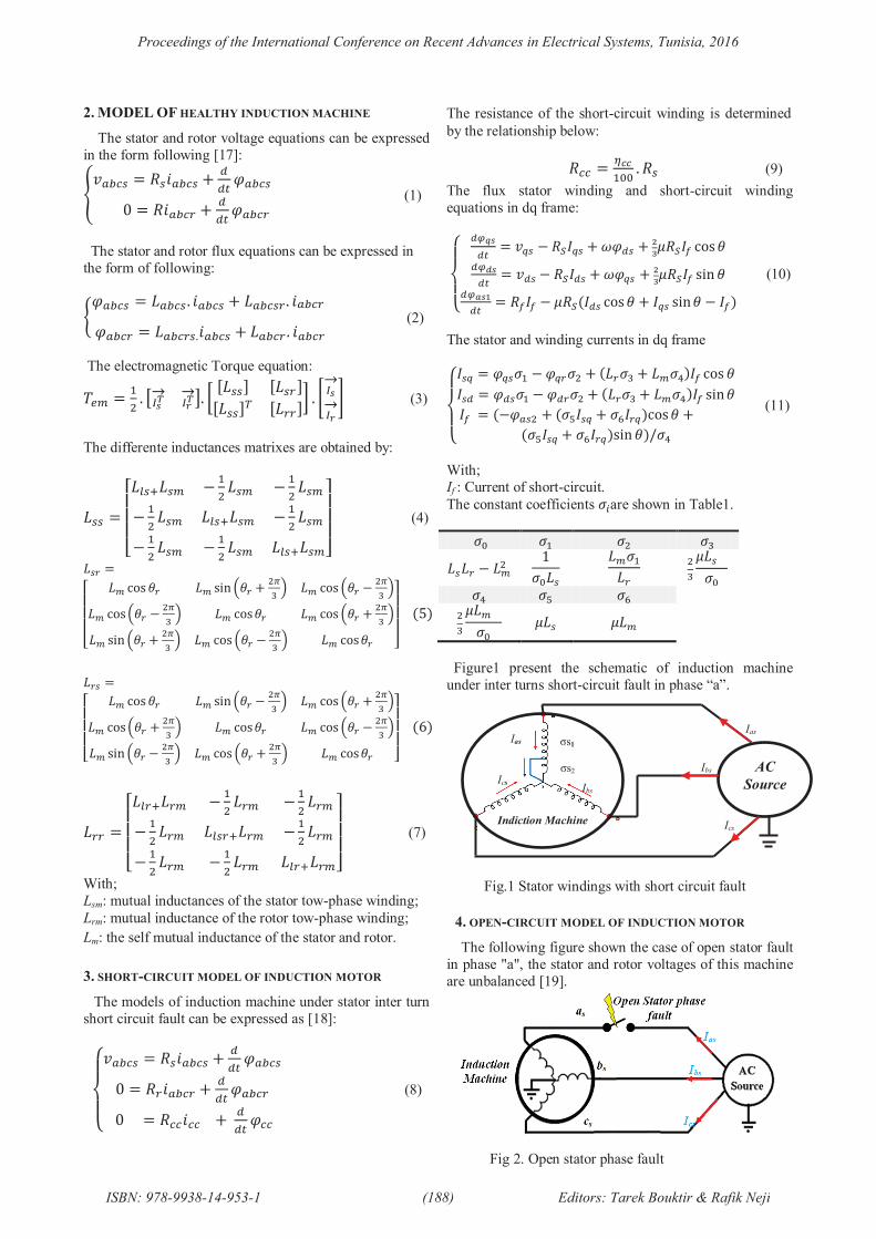
Figure1 present the schematic of induction machine
under inter turns short-circuit fault in phase “a”.
4. OPEN-CIRCUIT MODEL OF INDUCTION MOTOR
The following figure shown the case of open stator fault
in phase "a", the stator and rotor voltages of this machine
are unbalanced [19].
Fig 2. Open stator phase fault
Fig.1 Stator windings with short circuit fault
AC
Source
Ias
Ibs
Ics
σs2
σs1Ias
IcsIbs
Indiction Machine
Proceedings of the International Conference on Recent Advances in Electrical Systems, Tunisia, 2016
ISBN: 978-9938-14-953-1 (188) Editors: Tarek Bouktir & Rafik Neji
The voltage and flux systems are expressed by equations
(12) and (13) respectively:
!"#$% = &%'()* _+, . -"#$% / 001 . 2"#$%!"#$3 = &3 . -"#$_3 / 001 . 2"#$4*********** 5 (12)
62"#$% = 7%%'()* _+,. -"#$_% / 7%3'()* _+,. -"#$32"#$3 = 733 . -"#$3 / 73%'()* _+, . -"#$% 5 (13)
The resistance and inductance stator are given by the
following matrix:
&%'()* _+, = 89 9 99 :% 99 9 :%; (14)
7%%'()* _+, = <9 >?@7%A >?@7%A9 7B% / 7%A >?@7%A9 >?@7%A 7B% / 7%AC (15)
The mutual inductance matrix stator-rotor and rotor-stator
in faults case are given by:
7%3'()* _+, =7%A < 9 9 9sinDE3 / @FG H sinIE3J sinDE3 > @FG HsinDE3 > @FG H sinDE3 / @FG H sinIE3J C (16)
73%'()* _+, = 7%A K9 sinDE3 / @FG H sinDE3 > @FG H9 sinIE3J sinDE3 / >@FG H9 sinDE3 > @FG H sinIE3J L (17)
With;
**&%'()* _+, : stator resistance in fault case;7%%'()* _+, : stator inductance in fault case;7%3'()* _+,: mutual inductance stator-rotor in fault case;73%'()* _+,: mutual inductance rotor-stator in fault case.
5. MONITORING OF THE STATOR BY FUZZY LOGIC
1. Monitoring system
In this approach, we have used the fuzzy logic
inference system for monitoring of open phase or inter-
turns short-circuit faults in stator winding of the induction
machine. In this stage, we used linguistic variables and the
membership functions for describe the RMS amplitudes of
stator currents. An interface fuzzy system comprising the
rules and the data bases are established to support the
fuzzy inference system. The state of the machine is
monitoring by using the fuzzy logic system [20, 21].
2. Input-output variables of fuzzy system
The RMS of currents (RMS_Ias, RMS_Ibs and RMS_Ics)
and the state of stator, (CM) are respectively selected as
inputs and output variables of the fuzzy system.
All these variables are defined by using the fuzzy set
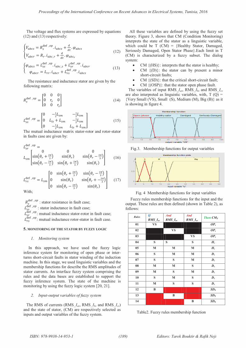
theory. Figure 3, shows that CM (Condition Monitoring)
interprets the state of the stator as a linguistic variable,
which could be T (CM) = {Healthy Stator, Damaged,
Seriously Damaged, Open Stator Phase}.Each limit in T
(CM) is characterized by a fuzzy subset. The dialog
system:
· CM {(HS)}: interprets that the stator is healthy;
· CM {(D)}: the stator can by present a minor
short-circuit faults;
· CM {(SD)}: that the critical short-circuit fault;
· CM {(OSP)}: that the stator open phase fault.
The variables of input RMS_Ias, RMS_Ibs and RMS_Ics
are also interpreted as linguistic variables, with, T (Q) =
{Very Small (VS), Small (S), Medium (M), Big (B)} as it
is showing in figure 4.
Fuzzy rules membership functions for the input and the
output. These rules are then defined (shown in Table 2), as
follows:
Table2. Fuzzy rules membership function
RulesIf
RMS_Ias
And
RMS_Ias
And
RMS_Ias
Then CMS
01 VS OPs
02 VS OPs
03 VS OPs
04 S S S Hs
05 M M M Hs
06 S M M Ds
07 S S M Ds
08 M M S Ds
09 M S M Ds
10 S M S Ds
11 M S S Ds
12 B SDS
13 B SDS
14 B SDS
Fig.3. Membership functions for output variables
Fig. 4 Membership functions for input variables
Proceedings of the International Conference on Recent Advances in Electrical Systems, Tunisia, 2016
ISBN: 978-9938-14-953-1 (189) Editors: Tarek Bouktir & Rafik Neji
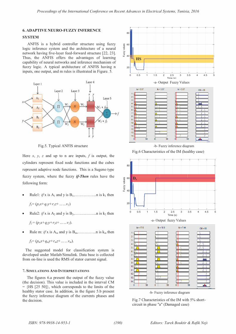
6. ADAPTIVE NEURO-FUZZY INFERENCE
SYSTEM
ANFIS is a hybrid controller structure using fuzzy
logic inference system and the architecture of a neural
network having five-layer feed-forward structure [22, 23].
Thus, the ANFIS offers the advantages of learning
capability of neural networks and inference mechanism of
fuzzy logic. A typical architecture of ANFIS having n
inputs, one output, and m rules is illustrated in Figure. 5.
Here x, y, z and up to n are inputs, f is output, the
cylinders represent fixed node functions and the cubes
represent adaptive node functions. This is a Sugeno type
fuzzy system, where the fuzzy if-Then rules have the
following form:
· Rule1: if x is A1 and y is B1,……………..n is k1 then
f1= (p1x+q1y+r1z+……v1)
· Rule2: if x is A2 and y is B2,……………..n is k2 then
f2 = (p2x+q2y+r2z+……v2).
· Rule m: if x is Am and y is Bm,…………..n is km then
f2= (pmx+qmy+rmz+……vm).
The suggested model for classification system is
developed under Matlab/Simulink. Data base is collected
from on-line is used the RMS of stator current signal.
7. SIMULATIONS AND INTERPRETATIONS
The figures 6.a present the output of the fuzzy value
(the decision). This value is included in the interval CM
= {HS [25 50]}, which corresponds to the limits of the healthy stator case. In addition, in the figure 5.b present
the fuzzy inference diagram of the currents phases and
the decision.
0 0.5 1 1.5 2 2.5 3 3.5 4 4.5 5
20
40
60
80
Time (s)
Fuzzy v
alu
es
HS
-a- Output Fuzzy Values
-b- Fuzzy inference diagram
Fig.6 Characteristics of the IM (healthy case)
-a- Output fuzzy Values
-b- Fuzzy inference diagram
Fig.7 Characteristics of the IM with 5% short-
circuit in phase "a" (Damaged case)
0 0.5 1 1.5 2 2.5 3 3.5 4 4.5 5
20
40
60
80
Time (s)
Fuzzy v
alu
es Ds
Fig.5. Typical ANFIS structure
Proceedings of the International Conference on Recent Advances in Electrical Systems, Tunisia, 2016
ISBN: 978-9938-14-953-1 (190) Editors: Tarek Bouktir & Rafik Neji
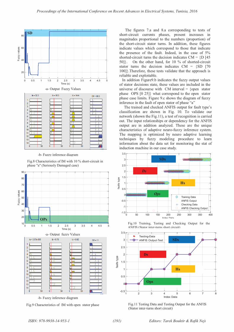
The figures 7.a and 8.a corresponding to tests of
short-circuit currents phases, present increases in
magnitudes proportional to the numbers (proportion) of
the short-circuit stator turns. In addition, these figures
indicate values which correspond to those that indicate
the presence of the fault. Indeed, in the case of 5%
shorted-circuit turns the decision indicates CM = {D [45
50]}. On the other hand, for 10 % of shorted-circuit
stator turns the decision indicates CM = {SD [70
100]}.Therefore, these tests validate that the approach is
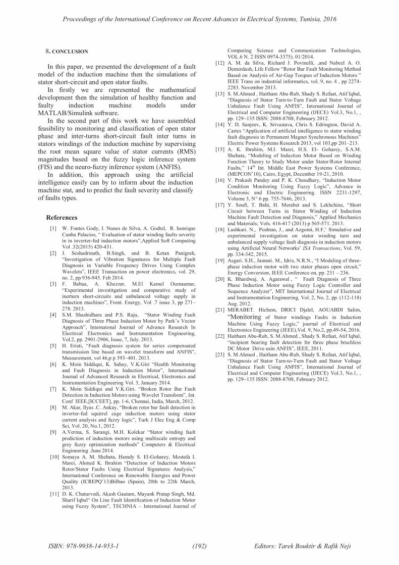
reliable and exploitable.In addition Figure9.b indicates the fuzzy output values
of stator decisions state, these values are included in the
universe of discourse with CM interval = {open stator
phase OPS [0 25]} what correspond to the open stator
phase case limits. Figure 9.c shows the diagram of fuzzy
inference in the fault of open stator of phase “a”
The trained and checked ANFIS output for fault type’s
classification are shown in Fig. 10. To validate our
network (shown the Fig.11), a test of recognition is carried
out. The input relationships or dependency for the ANFIS
output are in addition analyzed. These are the unique characteristics of adaptive neuro-fuzzy inference system.
The mapping is optimized by neuro adaptive learning
techniques by fuzzy modeling procedure to learn
information about the data set for monitoring the stat of
induction machine in our case study.
1 2 3 4 5 6 7 8-0.5
0
0.5
1
1.5
2
2.5
3
3.5
Index Data
faults t
ype
Testing-Data
ANFIS Output-Test 35% inter-turns
15% inter-turns
Healthy case
5% inter-turns
Fig.11 Testing Data and Testing Output for the ANFIS (Stator inter-turns short circuit)
Hs
Ops
Ds
SDs
0 50 100 150 200 250 300 350 400-1.5
-1
-0.5
0
0.5
1
1.5
2
2.5
3
3.5
Index Data
faults t
ype
Training Data
ANFIS Output
Checking Data
ANFIS Checking Output
Healthy case
5% inter-turns
15% inter-turns
35% inter-turns
Fig.10 Training, Testing and Checking Output for the
ANFIS (Stator inter-turns short circuit)
Hs
Ops
Ds
SDs
0 0.5 1 1.5 2 2.5 3 3.5 4 4.5 5
20
40
60
80
Time (s)
Fuzzy v
alu
es
SD
-a- Output Fuzzy Values
-b- Fuzzy inference diagram
Fig.8 Characteristics of IM with 10 % short-circuit inphase "a" (Seriously Damaged case)
-a- Output fuzzy Values
0 0.5 1 1.5 2 2.5 3 3.5 4 4.5 510
20
30
40
50
60
70
80
90
Time (s)
Fuzzy v
alu
es
OPs
-b- Fuzzy inference diagram
Fig.9 Characteristics of IM with open stator phase
Proceedings of the International Conference on Recent Advances in Electrical Systems, Tunisia, 2016
ISBN: 978-9938-14-953-1 (191) Editors: Tarek Bouktir & Rafik Neji
8. CONCLUSION
In this paper, we presented the development of a fault
model of the induction machine then the simulations of
stator short-circuit and open stator faults.
In firstly we are represented the mathematical
development then the simulation of healthy function and
faulty induction machine models under
MATLAB/Simulink software.
In the second part of this work we have assembled
feasibility to monitoring and classification of open stator phase and inter-turns short-circuit fault inter turns in
stators windings of the induction machine by supervising
the root mean square value of stator currents (RMS)
magnitudes based on the fuzzy logic inference system
(FIS) and the neuro-fuzzy inference system (ANFIS).
In addition, this approach using the artificial
intelligence easily can by to inform about the induction
machine stat, and to predict the fault severity and classify
of faults types.
References
[1] W. Fontes Gody, I. Nunes de Silva, A. Godtel, R. henrique
Cunha Palacios, “ Evaluation of stator winding faults severity
in in inverter-fed induction motors”,Applied Soft Computing
Vol .32(2015) 420-431.
[2] J. Seshadrinath, B.Singh, and B. Ketan Panigrah,
“Investigation of Vibration Signatures for Multiple Fault
Diagnosis in Variable Frequency Drives Using Complex
Wavelets”, IEEE Transaction on power electronics, vol. 29,
no. 2, pp 936-945. Feb 2014.
[3] F. Babaa, A. Khezzar, M.El Kamel Oumaamar,
“Experimental investitgation and comparative study of
inerturn short-circuits and unbalanced voltage supply in
induction machines”, Front. Energy, Vol .7 issue 3, pp 271–
278. 2013.
[4] S.M. Shashidhara and P.S. Raju, “Stator Winding Fault
Diagnosis of Three Phase Induction Motor by Park’s Vector
Approach”, Internatonal Journal of Advance Research In
Electircal Electronics and Instrumentation Engineering,
Vol.2, pp. 2901-2906, Issue, 7, July. 2013.
[5] H. Eristi, “Fault diagnosis system for series compensated
transmission line based on wavelet transform and ANFIS”,
Measurement, vol 46,p p 393–401. 2013.
[6] K. Moin Siddiqui, K. Sahay, V.K.Giri “Health Monitoring
and Fault Diagnosis in Induction Motor”, International
Journal of Advanced Research in Electrical, Electronics and
Instrumentation Engineering Vol. 3, January 2014.
[7] K. Moin Siddiqui and V.K.Giri. “Broken Rotor Bar Fault
Detection in Induction Motors using Wavelet Transform”, Int.
Conf IEEE,[ICCEET], pp. 1-6, Chennai, India, March, 2012.
[8] M. Akar, Ilyas .C. Ankay, “Broken rotor bar fault detection in
inverter-fed squirrel cage induction motors using stator
current analysis and fuzzy logic”, Turk J Elec Eng & Comp
Sci, Vol. 20, No.1, 2012.
[9] A.Verma, S. Sarangi, M.H. Kolekar “Stator winding fault
prediction of induction motors using multiscale entropy and
grey fuzzy optimization methods” Computers & Electrical
Engineering .June 2014.
[10] Somaya A. M. Shehata, Hamdy S. El-Goharey, Mostafa I.
Marei, Ahmed K. Ibrahim “Detection of Induction Motors
Rotor/Stator Faults Using Electrical Signatures Analysis,”
International Conference on Renewable Energies and Power
Quality (ICREPQ’13)Bilbao (Spain), 20th to 22th March,
2013.
[11] D. K. Chaturvedi, Akash Gautam, Mayank Pratap Singh, Md.
Sharif Iqbal“ On Line Fault Identification of Induction Motor
using Fuzzy System”, TECHNIA – International Journal of
Computing Science and Communication Technologies,
VOL.6 N. 2 ISSN 0974-3375). 01/2014.
[12] A. M. da Silva, Richard J. Povinelli, ,and Nabeel A. O.
Demerdash, Life Fellow “Rotor Bar Fault Monitoring Method
Based on Analysis of Air-Gap Torques of Induction Motors ”
IEEE Trans on industrial informatics, vol. 9, no. 4 , pp 2274-
2283. November 2013.
[13] S. M.Ahmed , Haitham Abu-Rub, Shady S. Refaat, Atif Iqbal,
“Diagnosis of Stator Turn-to-Turn Fault and Stator Voltage
Unbalance Fault Using ANFIS”, International Journal of
Electrical and Computer Engineering (IJECE) Vol.3, No.1, ,
pp. 129~135 ISSN: 2088-8708, February 2012.
[14] Y. D. Sanjeev, K. Srivastava, Chris S. Edrington, David A.
Cartes “Application of artificial intelligence to stator winding
fault diagnosis in Permanent Magnet Synchronous Machines”
Electric Power Systems Research 2013, vol 103,pp 201–213.
[15] A. K. Ibrahim, M.I. Marei, H.S. El- Goharey, S.A.M.
Shehata, “Modeling of Induction Motor Based on Winding
Function Theory to Study Motor under Stator/Rotor Internal
Faults,” 14th
Int. Middle East Power Systems Conference,
(MEPCON’10), Cairo, Egypt, December 19-21, 2010.
[16] V. Prakash Pandey and P. K. Choudhary, “Induction Motor
Condition Monitoring Using Fuzzy Logic”, Advance in
Electronic and Electric Engineering. ISSN 2231-1297,
Volume 3, N° 6 pp. 755-7646, 2013.
[17] Y. Soufi, T. Bahi, H. Merabet and S. Lekhchine, “Short
Circuit between Turns in Stator Winding of Induction
Machine Fault Detection and Diagnosis,” Applied Mechanics
and Materials; Vols. 416-417 (2013) p 565-571. 2013.
[18] Lashkari. N., Poshtan, J., and Azgomi, H.F,’ Simulative and
experimental investigation on stator winding turn and
unbalanced supply voltage fault diagnosis in induction motors
using Artificial Neural Networks’ ISA Transactions, Vol. 59,
pp. 334-342, 2015.
[19] Asgari. S.H., Jannati. M., Idris, N.R.N., “I Modeling of three-
phase induction motor with two stator phases open circuit,”
Energy Conversion, IEEE Conference on, pp. 231 – 236.
[20] K. Bhardwaj, A. Agarawal , “ Fault Diagnosis of Three
Phase Induction Motor using Fuzzy Logic Controller and
Sequence Analyzer”, MIT International Journal of Electrical
and Instrumentation Engineering, Vol. 2, No. 2, pp. (112-118)
Aug. 2012.
[21] MERABET. Hichem, DRICI Djalel, AOUABDI Salim,
“Monitoring of Stator windings Faults in Induction
Machine Using Fuzzy Logic,” journal of Electrical and
Electronics Engineering (JEEE),Vol. 9, No.2, pp.49-54, 2016.
[22] Haitham Abu-Rub, S. M.Ahmed , Shady S. Refaat, Atif Iqbal,
“incipient bearing fault detection for three phase bruchless
DC Motor Drive usin ANFIS”, IEEE, 2011.
[23] S. M.Ahmed , Haitham Abu-Rub, Shady S. Refaat, Atif Iqbal,
“Diagnosis of Stator Turn-to-Turn Fault and Stator Voltage
Unbalance Fault Using ANFIS”, International Journal of
Electrical and Computer Engineering (IJECE) Vol.3, No.1, ,
pp. 129~135 ISSN: 2088-8708, February 2012.
Proceedings of the International Conference on Recent Advances in Electrical Systems, Tunisia, 2016
ISBN: 978-9938-14-953-1 (192) Editors: Tarek Bouktir & Rafik Neji