Embed Size (px)
Citation preview

Operating Instructions (EN)
MODELS:
26'' Disk30'' Disk 34'' Disk
24'' Cylindrical 27'' Cylindrical 30'' Cylindrical 34'' Cylindrical
28'' Orbital 32'' Orbital
www.rpscorporation.com1711 South StreetRacine, WI 53404 (USA)(800) 450-9824 | (+001) 262-681-6470 VERSION 16.055© 2016 RPS Corporation MAGNUM-OP-EN
Read the Operators Manual before using the machine.
Read the Safety Messages before servicing machine.

- 2 - MAGNUM-OP-EN
INTRODUCTION
This manual is furnished with each new machine. This manual will allow the Operator to get the best performance out of your RPS manufactured Scrubber-Drier, Sweeper, Burnisher, or Orbital Scrubber. Read this manual thoroughly before operating or servicing the machine.
This machine will provide excellent performance, but the best results will be obtained at the most minimum costs if:
• The machine is regularly maintained - per the machine Preventative Maintenance instructions provided.
• The machine is operated with reasonable care and caution.
• The machine is maintained with manufacturer supplied parts.
ABOUT THIS MANUAL
TABLE OF CONTENTS: Tells you where to look in the manual.
SAFETY MESSAGES: Section contains important information regarding hazard or unsafe practices of the machine. Lev-els of hazards are identifi ed that could result in product or personal injury, or severe injury resulting in death.
OPERATION CONTROLS / MACHINE COMPONENTS: Shows you the different machine controls and features.
MACHINE SETUP: Tells you how to setup machine from un-crating to installing squeegee and brushes.
MACHINE OPERATION: Section is to familiarize the operator with the operation and function of the machine.
BATTERY CHARGING: Shows you how to charge the batteries (on-board and off board charging).
MAINTENANCE: This section contains preventative maintenance to keep the machine and it’s components in good work-ing condition. They are listed in this general order:
• Batteries• Scrub Brushes• Adjusting Squeegee• Service Schedule• Machine Trouble Shooting
TROUBLE SHOOTING: A list of common problems that may occur.
MACHINE SPECS: Tells you Machine Specifi cations for the various parts of the machine.
MACHINE INSTALL FORM: Should be fi lled out upon machine installation and faxed to 1-866-632-6961 or on-line at www.rpscorporation.com.
WARRANTY POLICY: Tells you coverage, exclusions and limitations to warranty.
NOTE: The serial number of your machine is located on the lower half of the control panel of the machine.
AS OUR POLICY IS ONE OF CONSTANT IMPROVEMENT - ALL INFORMATION AND SPECIFICATIONS ARE SUBJECT TO CHANGE WITHOUT NOTICE.
SERIAL NUMBER

MAGNUM-OP-EN - 3 -
TABLE OF CONTENTS
Introduction 2
About This Manual 2
Table of Contents 3
Safety Messages 4
Safety Label Locations 6
Operation Controls 7
Operation Controls 8
Machine Components 9
Machine Components 10
LCD Screen Menu Displays: 11
Machine Setup 12
Un-Crating Machine: 12Connecting Batteries: 12Adjusting Squeegee: 13Removing Squeegee: 13Replacing or Rotating Squeegee Blades: 13Installing Disk Pad Driver or Brush: 14Installing Driver Pads: 14Installing Cylindrical Brush: 15Installing EDGE/ORBITZ Pads: 16Leveling EDGE/ORBITZ Decks: 16Leveling PROPOLISH Disk Decks: 17Leveling Cylindrical Decks: 17Side Broom System: 18
Machine Operation 19
Pre-Cleaning Checklist: 19Operating Hints: 19One Pass Scrubbing: 20Scrub Only: 20Vacuum Only: 20Adjust Solution Flow: 21Adjust Curtains: 21Adjust Wipers : 21
Draining Solution Tank: 21Draining Recovery Tank: 21Open Recovery Lid: 22Flush Recovery Tank: 22Clean “Drain Saver”: 22Clean Vacuum Screen: 22Tip Tank: 23Squeegee Up: 23Squeegee Down: 23Deck Height Adjustment: 24Vacuum Motor: 24Solution Filter: 24Cleaning Solution Filter: 24
Battery Charging 25
External Battery Charging: 25
On-Board Charger 26
On-Board Battery Charging (Optional): 26
Battery Maintenance Guide 27
Safety: 27Inspection and Cleaning: 27Storage: 27Watering: 27
Maintenance 28
Daily Maintenance: 28Weekly Maintenance: 28Monthly maintenance: 28Yearly Maintenance: 28Storing Machine: 28Checking Battery Specifi c Gravity: 28
Magnum PM Records 29
Trouble-Shooting Central Command 31
Common Wear Parts 33
Round Disk Brushes: 33Round Disk Pads: 33EDGE Pads and Screens: 33New Style Cylindrical Brushes: 34Old Style Cylindrical Brushes: 34

- 4 - MAGNUM-OP-EN
SAFETY MESSAGES
You will see four kinds of safety reminders in this manual:
DANGERDANGER indicates a hazardous situation which, if not avoided, will result in death or serious injury.
WARNINGWARNING indicates a potentially hazardous situation which, if not avoided, could result in death or serious injury.
CAUTIONCAUTION indicates a potentially hazardous situation which, if not avoided, could result in minor or moderate injury or damage to this machine or nearby objects. CAU-TION also can be used to alert against unsafe practices.
NOTICENOTICE indicates information considered important, but not hazard-related. This safety message may be related to property damage or warranty warnings.
Your safety, and that of others, is very important. Operating this machine safely is an important responsibility.
DO NOT OPERATE THIS MACHINE:• Unless you are trained and authorized to do so• Unless you have read and understood this Operator’s Manual• On surfaces with greater than a 2% grade unless this machine is equipped with a functional parking brake• On surfaces with greater than an 8% grade at any time• On Loading Docks
WHEN OPERATING THIS MACHINE:• Remove loose objects from the fl oor that could be projected from the rotating Brushes• Keep your hands and feet away from the rotating Brushes• Do not operate this machine where fl ammable liquids are present• Use caution when maneuvering
BEFORE LEAVING THE MACHINE:• Park the machine on a level surface • Turn the machine off
BEFORE SERVICING THE MACHINE:• Disconnect the Batteries
DANGERExplosive hydrogen gas forms when Batteries are charging. An open fl ame or spark can cause this gas to explode. Serious personal injury or property damage could occur. Only charge the Batteries in this machine in a well ventilated area.
DANGERFlammable materials can cause an explosion or fi re. Do not use fl ammable materials in Tank or pick up.

MAGNUM-OP-EN - 5 -
WARNINGThe Batteries in this machine produce hazardous voltage which can cause electrical shock, burns and/or electrocution. Always disconnect Batteries before servicing this machine.
WARNINGWhen climbing or descending ramps, always drive machine forward. To avoid overturning the machine, Do not back down ramps. Do not drive across inclines. Do not turn while ascending or descending ramps. Over-turning the machine can cause serious injury or death.
WARNINGDo not use water that exceeds 135°F / 57°C. If wa-ter is above said temperature, this will void the Tank Warranty.
WARNINGDo not park this machine on ramps or slopes. Always park this machine on a level, hard surface. Do not oper-ate this machine outdoors or on uneven surfaces.
WARNINGThe Batteries in this machine contain sulfuric acid, which causes burns to skin. If battery acid contacts clothing or skin, rinse the effected area with cold water immediately. If battery acid gets on your face or in your eyes, fl ush the area immediately with cold water and seek medical attention.
WARNINGTo avoid electrical shock, do not operate this machine over electrical fl oor outlets.
WARNINGDress safely. Do not wear rings or metal wrist watches when servicing this machine, as they can cause an electrical short circuit which can cause serious burns.
WARNINGDo not remove, paint over or destroy warning decals. If warning decals become damaged, call 1-262-681-3583 for free replacements.
WARNINGDress safely. Do not wear a neck tie, scarf, or any loose or dangling clothing while operating this machine. Loose or dangling clothing or neck-wear can tangle in rotating parts, causing serious injury or death.
WARNINGAlways turn off this machine before leaving it unat-tended. Do not allow untrained persons to operate this machine.
WARNINGNO RIDERS. Do not carry passengers on this ma-chine. Do not use this machine as a stepladder or work platform.
WARNINGUnderstand the dynamic braking system before you operate the machine on ramps. Machine may coast.
WARNINGBefore you service a Battery, always wear face protec-tion, protective gloves and protective clothing. Battery acid or battery explosion can cause serious injuries.
CAUTIONTo avoid damage to this machine, use only cleaning solutions and replacement parts recommended by the manufacturer.
CAUTIONDo not operate this machine if any parts have been damaged or removed.
CAUTIONAlways use the automatic battery charger provided by the manufacturer of this machine to charge the Batter-ies of this machine. It is designed to charge the Batter-ies at the appropriate rate. If you must use a different charger, disconnect the Batteries before charging to avoid damage to the electronic speed controller.
CAUTIONTo avoid damage to the electronic control components of this machine, Do not store this machine outdoors. Do not pressure wash this machine.

- 6 - MAGNUM-OP-EN
SAFETY LABEL LOCATIONS
Read and obey all Safety Labels on your MAGNUM Floor Scrubber. If you have questions about these labels, ask your supervisor.
These images indicate where on the MAGNUM Safety Labels are located. If ever the labels become illegible, worn off, or torn, promptly report it to your supervisor and replace it.
USE ONLY DISTILLED WATER IN THE BATTERIES. USE ONLY THE OEM CHARGER PROVIDED WITH THE MA-CHINE. ALWAYS DISCONNECT THE BATTERY BEFORE SERVICING THE MACHINE.
REFER TO MANUAL OR CALL +011-262-681-3583
DANGEREXPLOSION RISK!
EXPLOSIVE HYDROGEN GAS FORMS WHEN BATTERIES ARE CHARGING. AN OPEN FLAME OR SPARK CAN CAUSE THIS GAS TO EXPLODE. ONLY CHARGE THE BATTERIES IN THIS MA-CHINE IN A WELL VENTILATED AREA.
TO AVOID DAMAGE TO THIS MACHINE:
˚F/ 54˚
REFER TO MANUAL OR CALL +011-262-681-3583
DANGEREXPLOSION RISK!
BATTERY CHARGING LABELPART #: 253-7280
TANK LABELPART #: 5-728

MAGNUM-OP-EN - 7 -
OPERATION CONTROLS
1. SPRAY JET [BLUE] (OPTIONAL): Activates Water Pump for remote Spray Wand
2. “ON-BOARD” SOAP SYSTEM [GRAY] (OPTIONAL): Dispenses soap directly to the Scrubdeck level
3. ECON TOGGLE SWITCH [GREEN] (OPTIONAL): Reduces power to give machine a longer run time
4. KEY SWITCH: Turns power of the machine ON and OFF
5. LOAD TOGGLE SWITCH [ORANGE] (OPTIONAL): Engages different Scrubdeck parameters for increased RPM for Stripping and Polishing
6. SQUEEGEE LIFT LEVER: Raises and lowers the Squeegee
7. MAIN POWER SWITCH: Turns power of the machine ON and OFF
8. SPEED CONTROL KNOB: Controls the speed of the Traction Drive - Turn counter-clockwise to reduce speed
9. REVERSE SWITCH: Pull back for machine drive reverse
10. LCD SCREEN: Lists functions and settings of the machine
11. SOLUTION FLOW CONTROL TOGGLE [BLUE]: Push down (-) to reduce and push up (+) to increase the solution fl ow
12. SCRUBDECK SWITCH: Raises and lowers the Scrubdeck
13. MENU CONTROL: Scrolls through different options on the LCD display - there are 3 different screens it will scroll through
14. DOWN PRESSURE TOGGLE SWITCH [BLACK]: Controls the pressure to the Scrubdeck - push up (+) for higher down pressure, down (-) for lower pressure
15. CHARGER PORT: Red 50 used to receive charger input for optional external charger
6 7 8 9 10 11 12 13
14
15
1
2
3
4
5
- 8 - MAGNUM-OP-EN
OPERATION CONTROLS
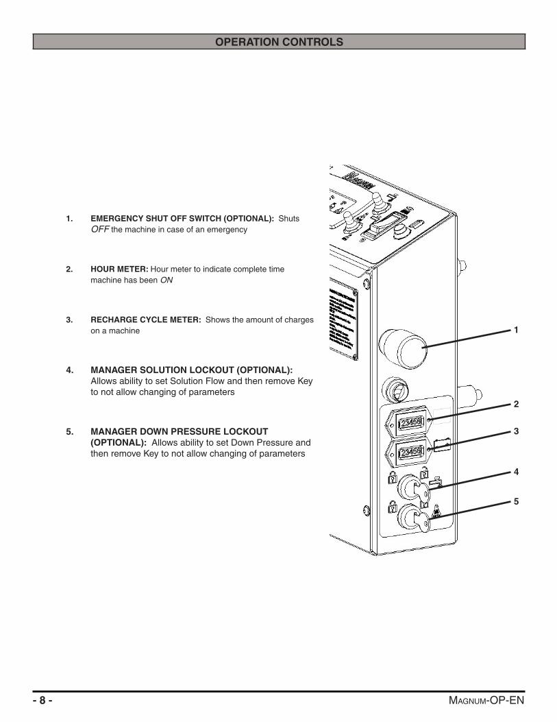
1. EMERGENCY SHUT OFF SWITCH (OPTIONAL): Shuts OFF the machine in case of an emergency
2. HOUR METER: Hour meter to indicate complete time machine has been ON
3. RECHARGE CYCLE METER: Shows the amount of charges on a machine
4. MANAGER SOLUTION LOCKOUT (OPTIONAL): Allows ability to set Solution Flow and then remove Key to not allow changing of parameters
5. MANAGER DOWN PRESSURE LOCKOUT (OPTIONAL): Allows ability to set Down Pressure and then remove Key to not allow changing of parameters
1
2
3
4
5
MAGNUM-OP-EN - 9 -
MACHINE COMPONENTS
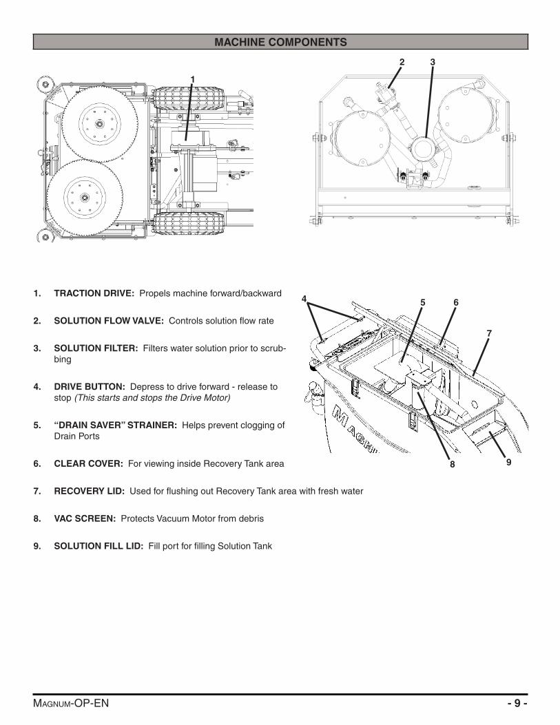
1. TRACTION DRIVE: Propels machine forward/backward
2. SOLUTION FLOW VALVE: Controls solution fl ow rate
3. SOLUTION FILTER: Filters water solution prior to scrub-bing
4. DRIVE BUTTON: Depress to drive forward - release to stop (This starts and stops the Drive Motor)
5. “DRAIN SAVER” STRAINER: Helps prevent clogging of Drain Ports
6. CLEAR COVER: For viewing inside Recovery Tank area
7. RECOVERY LID: Used for fl ushing out Recovery Tank area with fresh water
8. VAC SCREEN: Protects Vacuum Motor from debris
9. SOLUTION FILL LID: Fill port for fi lling Solution Tank
1
32
5 6
7
4
98
- 10 - MAGNUM-OP-EN
MACHINE COMPONENTS
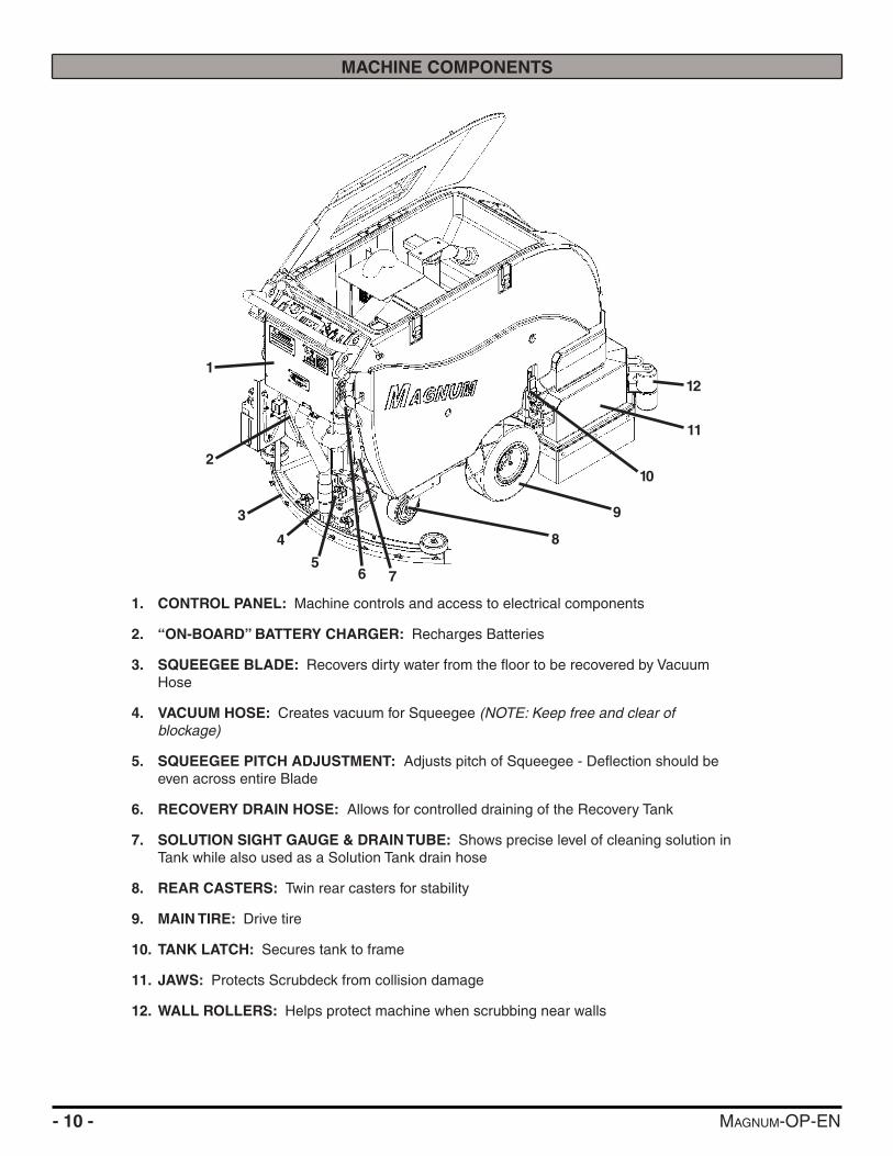
1. CONTROL PANEL: Machine controls and access to electrical components
2. “ON-BOARD” BATTERY CHARGER: Recharges Batteries
3. SQUEEGEE BLADE: Recovers dirty water from the fl oor to be recovered by Vacuum Hose
4. VACUUM HOSE: Creates vacuum for Squeegee (NOTE: Keep free and clear of blockage)
5. SQUEEGEE PITCH ADJUSTMENT: Adjusts pitch of Squeegee - Defl ection should be even across entire Blade
6. RECOVERY DRAIN HOSE: Allows for controlled draining of the Recovery Tank
7. SOLUTION SIGHT GAUGE & DRAIN TUBE: Shows precise level of cleaning solution in Tank while also used as a Solution Tank drain hose
8. REAR CASTERS: Twin rear casters for stability
9. MAIN TIRE: Drive tire
10. TANK LATCH: Secures tank to frame
11. JAWS: Protects Scrubdeck from collision damage
12. WALL ROLLERS: Helps protect machine when scrubbing near walls
2
1
3
4
56 7
8
9
11
10
12
MAGNUM-OP-EN - 11 -
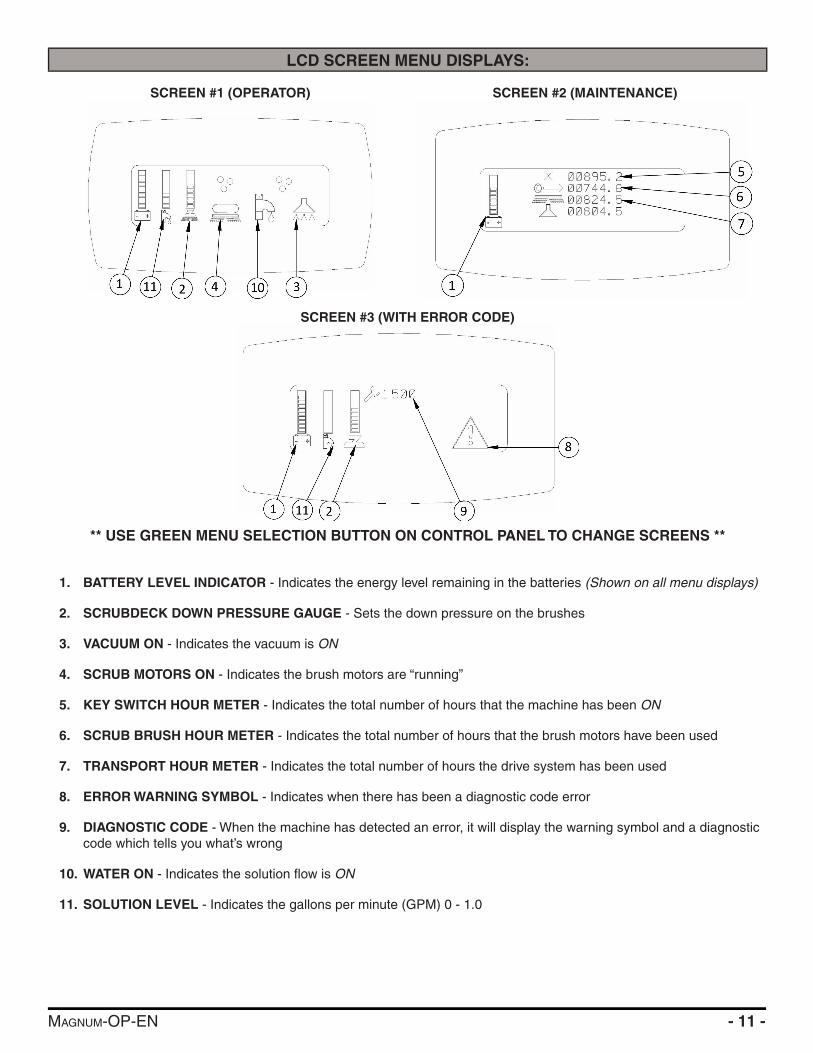
LCD SCREEN MENU DISPLAYS:
** USE GREEN MENU SELECTION BUTTON ON CONTROL PANEL TO CHANGE SCREENS **
1. BATTERY LEVEL INDICATOR - Indicates the energy level remaining in the batteries (Shown on all menu displays)
2. SCRUBDECK DOWN PRESSURE GAUGE - Sets the down pressure on the brushes
3. VACUUM ON - Indicates the vacuum is ON
4. SCRUB MOTORS ON - Indicates the brush motors are “running”
5. KEY SWITCH HOUR METER - Indicates the total number of hours that the machine has been ON
6. SCRUB BRUSH HOUR METER - Indicates the total number of hours that the brush motors have been used
7. TRANSPORT HOUR METER - Indicates the total number of hours the drive system has been used
8. ERROR WARNING SYMBOL - Indicates when there has been a diagnostic code error
9. DIAGNOSTIC CODE - When the machine has detected an error, it will display the warning symbol and a diagnostic code which tells you what’s wrong
10. WATER ON - Indicates the solution fl ow is ON
11. SOLUTION LEVEL - Indicates the gallons per minute (GPM) 0 - 1.0
SCREEN #1 (OPERATOR) SCREEN #2 (MAINTENANCE)
SCREEN #3 (WITH ERROR CODE)

- 12 - MAGNUM-OP-EN
MACHINE SETUP
UN-CRATING MACHINE:
Carefully check the crate for any signs of damage and that the batteries are in the unit.
To un-crate the machine, remove banding strips from around the crate. Take off the top and sides and dispose properly. Remove brackets from machine wheels. Remove bolts from pallet, then remove board. Carefully roll the machine off of the base. Notify the carrier immediately if concealed damage is discovered.
CONNECTING BATTERIES:
Your machine is equipped with (4×) 6-Volt/ 245 AH, (4×) 6-Volt/ 325 AH, (4×) 6-Volt/ 360 AH, or (4×) 6-Volt/ 360 AH Wet Lead Acid, AGM, or Deep Cycle Batteries which form a 24 Volt system.
(SEE PICTURE BELOW OR BATTERY DISCONNECT LABEL FOR CORRECT CABLE CONNECTIONS)
1. Turn all switches to the OFF position and remove Key (if machine is equipped with Optional Key Switch).
2. Attach all Battery Cables to Terminals as shown below.
3. Turn ON main power switch and check the battery condition meter to ensure correct installation. Charge Batteries if needed (SEE BATTERY CHARGING).
NOTICEBatteries are a possible environmental hazard. Consult your Battery supplier for safe disposal methods.
NOTICEOrientation of Batteries is critical for cables to reach.
ATTACHING SQUEEGEE:
1. Lower the Squeegee Mounting Plate by rotating the Squeegee Lift Lever (A) in a clockwise motion (SEE BELOW).
2. Loosen the two knobs (B) on the Squeegee and slide them into the slots in the Squeegee Mounting Plate (SEE BELOW).
3. Tighten the two knobs and connect the Vacuum Hose (C) from the machine to the Squeegee (SEE BELOW).
4. You may have to adjust the Squeegee Pitch (SEE ADJUSTING SQUEEGEE ON THE NEXT PAGE)
6V 6V
6V 6V
24 VOLTS
A
BB
C

MAGNUM-OP-EN - 13 -
ADJUSTING SQUEEGEE:1. Turning adjustment knob (A) clockwise (tightening) will
lower tips and raise the center of the Squeegee (SEE BELOW).
2. This Squeegee is adjusted too far back and will not pick up on the corners (SEE BELOW).NOTE: Tips off of the fl oor.
3. This Squeegee is adjusted too far forward and will not pick up in the center (SEE BELOW).NOTE: Center spaced off the fl oor.
4. This Squeegee is adjusted just right with good defl ection across the entire rear blade (SEE BELOW).
REMOVING SQUEEGEE:
1. With the Squeegee in the up position, turn machine power OFF.
2. Disconnect Vacuum Hose (A) from Squeegee and loosen both knobs (B) (SEE BELOW).
3. Pull Squeegee assembly backward from the lifting carrier.
4. Inspect or repair as needed and reinstall.
REPLACING OR ROTATING SQUEEGEE BLADES:
NOTICEFOR SAFETY: Before leaving or servicing the machine, stop on a level surface, turn off machine and remove key.
1. Remove the Squeegee Assembly from the machine. Remove Blade retainer strap and remove Squeegee Blade.
2. Rotate the Squeegee to new edge position or replace as required.
3. Install Blade on the locating pins of Squeegee Assembly.
4. Install Squeegee Retainer Strap.
5. Fasten and lock knobs, starting in the center and moving outwards.
A
BB
A

- 14 - MAGNUM-OP-EN
INSTALLING DISK PAD DRIVER OR BRUSH:
1. Turn on machine power.
2. Raise the Scrubdeck by depressing the Brush switch to the up and OFF position and turn the machine power back OFF. Remove Key.
3. If the machine is equipped with Jaws, remove pin (A) and undo latch (B) on front of Jaws to open them (SEE BELOW).
4. If the machine is equipped with a Shroud, unscrew Shroud Star Knobs (C) and pull Shroud forwards - Away from the front of the Scrubdeck (SEE BELOW).
5. Attach Brushes or Pads to Motor Drives. Squeeze the scissor locking device and lift brush up on to the motor drive hub. Make sure the scissors close and lock on the brushes (SEE BELOW).
INSTALLING DRIVER PADS:
1. Select the correct Pads that best meet your cleaning application needs. Consult your local dealer for assistance.
2. Pad Installation: Attach Pads to Pad Drivers before connecting drivers to motor hub. Screw center clip (E) into place (SEE BELOW).
E
SCRUB BRUSHES / PADS:There are many different types of brushes available to cover applications from cleaning heavily soiled fl oors to polishing.
A Pad Driver is also available to take advantage of the many cleaning pads on the market. Please refer to the “Common Wear Parts” page to assist in selecting the proper Brush / Pad for the work at hand.
AB
C
D
MAGNUM-OP-EN - 15 -
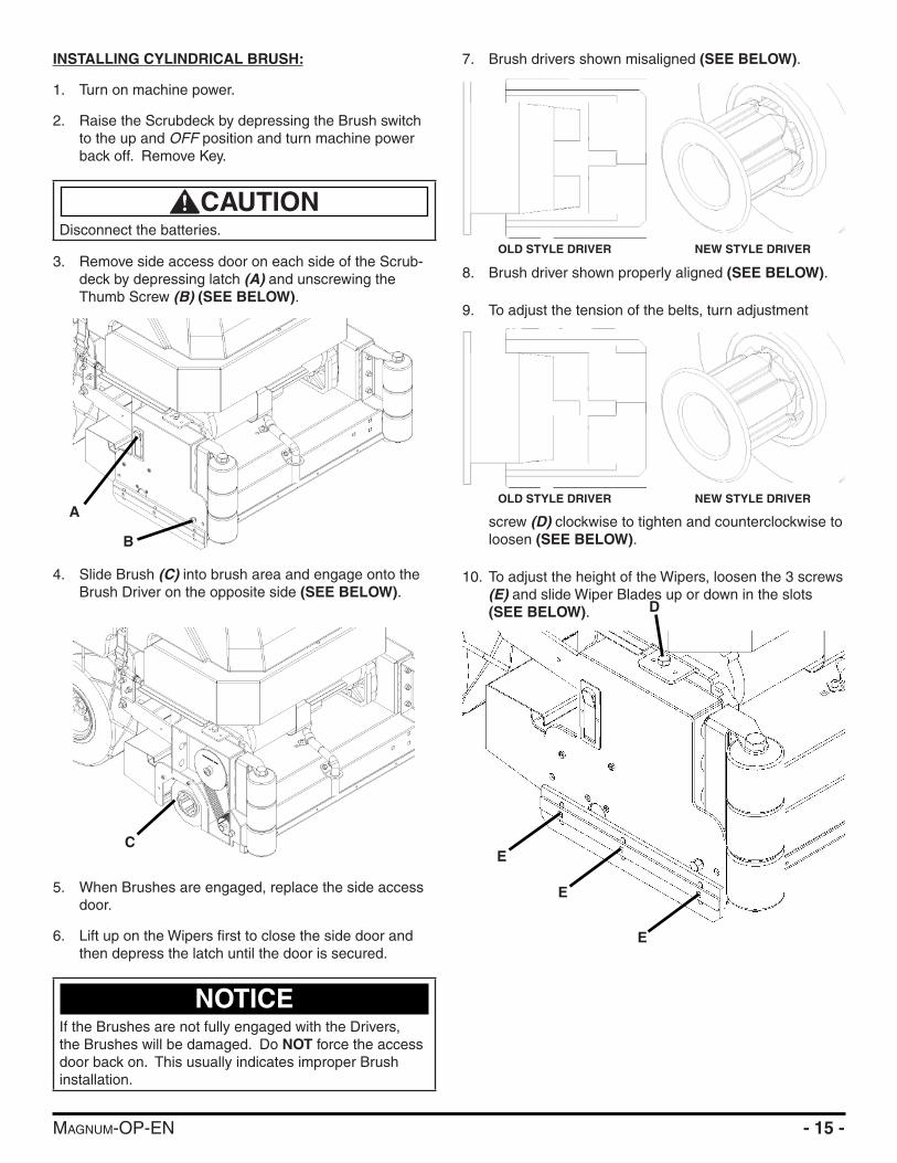
INSTALLING CYLINDRICAL BRUSH:
1. Turn on machine power.
2. Raise the Scrubdeck by depressing the Brush switch to the up and OFF position and turn machine power back off. Remove Key.
CAUTIONDisconnect the batteries.
3. Remove side access door on each side of the Scrub-deck by depressing latch (A) and unscrewing the Thumb Screw (B) (SEE BELOW).
4. Slide Brush (C) into brush area and engage onto the Brush Driver on the opposite side (SEE BELOW).
5. When Brushes are engaged, replace the side access door.
6. Lift up on the Wipers fi rst to close the side door and then depress the latch until the door is secured.
NOTICEIf the Brushes are not fully engaged with the Drivers, the Brushes will be damaged. Do NOT force the access door back on. This usually indicates improper Brush installation.
7. Brush drivers shown misaligned (SEE BELOW).
8. Brush driver shown properly aligned (SEE BELOW).
9. To adjust the tension of the belts, turn adjustment
screw (D) clockwise to tighten and counterclockwise to loosen (SEE BELOW).
10. To adjust the height of the Wipers, loosen the 3 screws (E) and slide Wiper Blades up or down in the slots (SEE BELOW).
A
B
C
OLD STYLE DRIVER NEW STYLE DRIVER
OLD STYLE DRIVER NEW STYLE DRIVER
D
E
E
E

- 16 - MAGNUM-OP-EN
INSTALLING EDGE/ORBITZ PADS:
1. Turn on machine power.
2. Raise the Scrubdeck by depressing the Brush switch to the UP and OFF position and turn machine power back off.
3. Select the correct Pads that best meet your cleaning application. Consult your local dealer for assistance.
4. Remove any Pad previously attached to the EDGE/ORBITZ Grip Face by pulling down from the corners (SEE BELOW).
5. Once Grip Face is clear of any Pads, place pad want-ed for application centered on the Grip Face (This will leave a ½’’ overhang on all sides).
6. Press upwards on the Pad to secure it in place (SEE BELOW).
7. With Pad attached securely to Grip Face of EDGE/ORBITZ Deck, the machine is ready to use.
LEVELING EDGE/ORBITZ DECKS:
NOTICEAll Scrubdeck’s should be level at time of machine delivery. If machine Scrubdeck is not level - Contact your Servicing Dealer.
1. Drive machine to a fl at level surface and turn machine OFF.
2. Ensure that Scrubdeck is in full upright position.
3. Turn on machine and depress the brush switch. Just before the Scrubdeck’s EDGE/ORBITZ Pad touches the ground, turn machine OFF.
4. Tip Machine Tank back to gain access to the Scrubdeck’s Adjustable arms.
5. Loosen the Locking Nut (A) on the Adjustable Deck Arms. Turn the Hexagonal Arm (B) on each side of the Scrubdeck to level it. Use the Scrubdeck Levels (C) built into the deck (SEE BELOW).
6. Extending the Adjustable Arms raise the front and lowers the rear of the Scrubdeck. After Scrubdeck has been leveled - tighten Locking Nuts (A).
NOTICENEVER place aggressive Pads (Maroon Prep, Dominator HD Strip, etc.) directly onto the Grip Face. Always use Red or Blue Spacer pad to prevent Grip Face damage.
A
C C
B
MAGNUM-OP-EN - 17 -
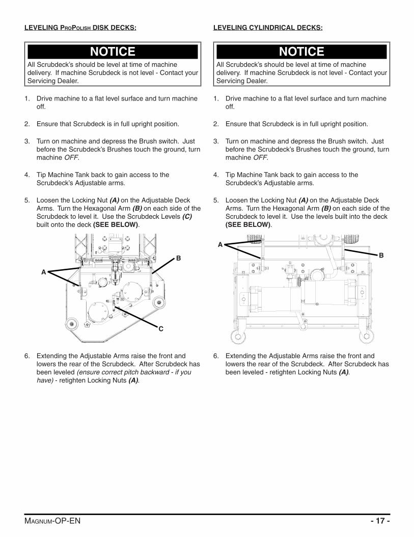
LEVELING PROPOLISH DISK DECKS:
NOTICEAll Scrubdeck’s should be level at time of machine delivery. If machine Scrubdeck is not level - Contact your Servicing Dealer.
1. Drive machine to a fl at level surface and turn machine off.
2. Ensure that Scrubdeck is in full upright position.
3. Turn on machine and depress the Brush switch. Just before the Scrubdeck’s Brushes touch the ground, turn machine OFF.
4. Tip Machine Tank back to gain access to the Scrubdeck’s Adjustable arms.
5. Loosen the Locking Nut (A) on the Adjustable Deck Arms. Turn the Hexagonal Arm (B) on each side of the Scrubdeck to level it. Use the Scrubdeck Levels (C) built onto the deck (SEE BELOW).
6. Extending the Adjustable Arms raise the front and lowers the rear of the Scrubdeck. After Scrubdeck has been leveled (ensure correct pitch backward - if you have) - retighten Locking Nuts (A).
LEVELING CYLINDRICAL DECKS:
NOTICEAll Scrubdeck’s should be level at time of machine delivery. If machine Scrubdeck is not level - Contact your Servicing Dealer.
1. Drive machine to a fl at level surface and turn machine off.
2. Ensure that Scrubdeck is in full upright position.
3. Turn on machine and depress the Brush switch. Just before the Scrubdeck’s Brushes touch the ground, turn machine OFF.
4. Tip Machine Tank back to gain access to the Scrubdeck’s Adjustable arms.
5. Loosen the Locking Nut (A) on the Adjustable Deck Arms. Turn the Hexagonal Arm (B) on each side of the Scrubdeck to level it. Use the levels built into the deck (SEE BELOW).
6. Extending the Adjustable Arms raise the front and lowers the rear of the Scrubdeck. After Scrubdeck has been leveled - retighten Locking Nuts (A).
A
B
A
B
C
- 18 - MAGNUM-OP-EN
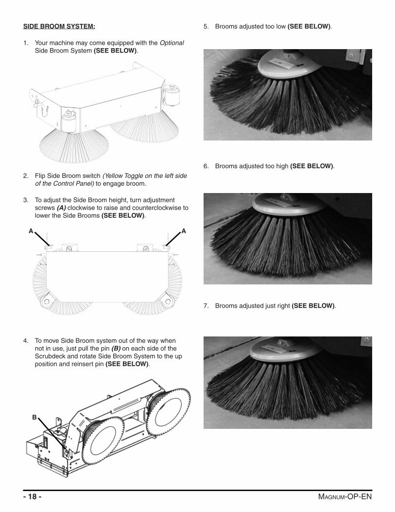
SIDE BROOM SYSTEM:
1. Your machine may come equipped with the Optional Side Broom System (SEE BELOW).
2. Flip Side Broom switch (Yellow Toggle on the left side of the Control Panel) to engage broom.
3. To adjust the Side Broom height, turn adjustment screws (A) clockwise to raise and counterclockwise to lower the Side Brooms (SEE BELOW).
4. To move Side Broom system out of the way when not in use, just pull the pin (B) on each side of the Scrubdeck and rotate Side Broom System to the up position and reinsert pin (SEE BELOW).
5. Brooms adjusted too low (SEE BELOW).
6. Brooms adjusted too high (SEE BELOW).
7. Brooms adjusted just right (SEE BELOW).
AA
B

MAGNUM-OP-EN - 19 -
MACHINE OPERATION
PRE-CLEANING CHECKLIST:
Read and understand the Safety Messages section on Pages 3 and 4 before operating the machine.
1. Check Battery Condition Gauge on the Control Panel. Make sure Batteries are fully charged before using.
2. Check the condition of the Pads or Brushes.
3. Check the condition of the Squeegee Blades.
4. Raise the Scrubdeck and Squeegee before transporting then transport the machine to the fi lling station.
5. Turn the machine OFF.
6. Fill the Tank with up to 17 gallons of clean water either at the front fi ll port (A) or rear fi ll port (B) (SEE BELOW).
7. Add APPROVED cleaning chemical to the Tank. Use the proper dilution ratio indicated on the bottle. Contact us at 1(800)-634-4060 or +011-262-681-3583 if unsure.
NOTICEThe clear tube (Solution Sight Tube) (C) at the rear of the machine indicates the amount of water in the Tank (SEE BELOW).
DANGEREXPLOSION RISK! Flammable materials can cause an explosion or fi re. Do NOT use fl ammable materials in Tank or pick up.
CAUTIONTO AVOID DAMAGE TO THIS MACHINE:• Use APPROVED detergents only• Water temperature must not exceed 130˚F/54˚C• Do NOT use high-percentage Bleach mixture
OPERATING HINTS:
1. Observe the amount of solution the machine is dispensing on the fl oor and adjust to the desired fl ow. To increase the solution fl ow rate, press the Solution Control Toggle up. To shut the solution OFF completely, just release the Drive button, or use dash mounted switch.
2. Keep an eye on the clear Vacuum cover to make sure that there is not any foamy buildup in the Recovery Tank. If excess foam begins to develop, pour a recommended foam control solution into the Recovery Tank. Foam is usually an indication of excessive soap.
3. Always operate at lower speeds when scrubbing around walls and objects. You should reduce the speed to maintain control when turning.
4. If Squeegee starts to streak, raise and wipe the Blades with a clean cloth. if the problem continues, check the Squeegee Blades for wear or damage and rotate if needed. You may need to pre-sweep before scrubbing. (Only Use OEM Parts)
5. Change or turn over Brushes / Pads when dirty.
6. Stay clear of objects protruding from the fl oor such as sockets, grates, etc, for they will damage the Brushes / Pads and Squeegee Blades.
7. Always keep an eye on your gauges. They let you know the status of a particular system at a glance. If your battery gauge is reading low you much stop immediately and recharge. Running the Batteries dead will result in damage to the Batteries.
8. When you run out of solution, raise the Scrubdeck and continue to Vacuum the remaining water until it is all consumed. The Solution Sight Tube is used to indicate the level of detergent remaining in the Tank.
9. When you are ready to stop, raise the Scrubdeck, turn OFF the solution switch, raise the Squeegee and drive the machine back to the charging area. Be sure to drain both Tanks before storing the machine.
A
B C

- 20 - MAGNUM-OP-EN
ONE PASS SCRUBBING:
1. Turn on machine Power Switch (A), make sure the Speed Control Knob (B) is at a lower setting.
2. Lower the Squeegee by rotating the Squeegee Lift Lever (C) all the way to the right (Vacuum Motor will turn on automatically).
3. Lower Scrubdeck head to the fl oor by pressing the Scrubdeck Switch on the Control Panel (G).
4. Press up or down on the Solution Flow Toggle (H) to regulate the amount of solution fl ow.
5. Begin scrubbing by pressing one of the green Drive Buttons (D) on the handle bars. Adjust the Speed Control Knob (B) to the desired setting.
6. Once the machine begins to move, check the down pressure on the LCD screen (F). To adjust the down pressure, push toggle switch (I) forward to increase pressure backward to decrease pressure. Start scrubbing at the #1 or #2 marks. Do not use the #4 or #5 marks without management’s approval.
7. To operate the machine in reverse, simply pull the Reverse switch (E) back towards the Handlebar. The reverse speed is set to approximately 50% of the forward speed.
8. To stop the machine, let go of the Drive Buttons (D).
SCRUB ONLY:
1. Turn on machine Power Switch (A) while making sure the Speed Control Knob (B) is at a lower setting.
2. Lower Scrubdeck head to the fl oor by pressing the Scrubdeck Switch on the Control Panel (G)
3. Press the Solution Flow Toggle button (H) up or down to regulate the amount of solution fl ow.
4. Begin scrubbing by pressing one of the green Drive Buttons (D) on the Handlebars. Adjust the Speed Control Knob (B) to the desired setting.
5. To operate the machine in reverse, simply pull the Reverse Switch (E) back towards the Handlebar. The reverse speed is set to approximately 50% of the forward speed.
6. To stop the machine, let go of the Drive Buttons (D).
VACUUM ONLY:
1. Turn on machine Power Switch (A) while making sure the Speed Control Knob (B) is at a lower setting.
2. Lower the Squeegee by rotating the Squeegee Lift Lever (C) all the way to the right (Vacuum Motor will turn on automatically).
3. Begin vacuuming by pressing one of the green Drive Buttons (D) on the Handlebars.
B
GE
HAC
D D
IF

MAGNUM-OP-EN - 21 -
ADJUST SOLUTION FLOW:
1. Push UP (+) on the Solution Flow Toggle (A) to increase the solution fl ow and push DOWN (-) on the toggle to decrease solution fl ow (SEE BELOW).
ADJUST CURTAINS:
1. For Jaw curtains, release Jaw latch (B) and remove Jaw Pin (C) on the front of the Jaws to open them (SEE BELOW).
2. Loosen curtain band screws (D) (SEE BELOW).
3. To adjust curtain to the desired height, just slide the curtain up or down in the slits and tighten screws.
4. Close Jaws - reconnect the latch and reinsert the pin.
ADJUST WIPERS :
1. For Cylindrical side Wipers, loosen Wiper band screws (E) (SEE BELOW).
2. To adjust Wiper to the desired height, just slide the Wiper up or down in the slots and tighten the screws.
DRAINING SOLUTION TANK:To drain unwanted cleaning solution from the Solution Tank, perform the following steps:(SEE BELOW)1. Pull the clear Sight Tube/Drain
Hose (F) off barbed fi tting.2. Rinse out Tank and solution fl ow
system with clean water.
DRAINING RECOVERY TANK:
Always empty Recovery Tank when refi lling the Solution Tank. You can refi ll the Solution Tank while the Recovery Tank is draining.
1. To drain the Recovery Tank remove Drain Hose (G) from hook at rear of Tank and pop off cap (SEE BELOW).
NOTICELeave Recovery Lid open while draining Tanks. Rinse thoroughly.
NOTICEGet Supervisor APPROVAL fi rst and drain at APPROVED locations only.
CB
D
E
F
G
A

- 22 - MAGNUM-OP-EN
OPEN RECOVERY LID:1. Release both latches (A) on Recovery
Tank lid (SEE BELOW).
2. Rotate lid fully open.
FLUSH RECOVERY TANK:1. Rinse the Recovery Tank after every use
(B). This will prevent heavy build-up on the bottom of the tank, foul odors as well as clogging of the Drain Hose (SEE BELOW).
2. Remove Drain Hose (C) and open to allow for drainage of the Recovery Tank (SEE BELOW).
3. Flush Recovery Tank with water hose.4. After rinsing, reattach the Drain Hose
(C) on hook (SEE ABOVE).
NOTICEKeep water off of Control Panel.
CLEAN “DRAIN SAVER”:
With Recovery Lid open and Tank fully drained:
1. Remove 2'' Squeegee Intake Hose (D) from “Drain Saver” strainer (E) (SEE BELOW).
2. Remove stainless screen and dispose of debris.
3. Rinse screen with fresh water from the outside while holding the screen upside down. This will allow for better cleaning.
4. Replace the screen into the bracket.
5. Replace 2'' Squeegee Intake Hose.
CLEAN VACUUM SCREEN:
With Recovery Lid open and Tank fully drained:
1. Remove Vacuum Screen retaining clip (F) (SEE BELOW).
2. Pull Vacuum Screen and fl oat ball assembly (G) off of the Vacuum Box.
3. Rinse with hot water.
4. Dry thoroughly.
5. Replace the Vacuum Screen onto box.
6. Replace and tighten retaining clip.
A
B
C
D
E
F
G

MAGNUM-OP-EN - 23 -
TIP TANK:
1. Fully drain Solution Tank and the Recovery Tank.
2. Remove Squeegee.3. Unlatch Tank Latch (A) on each side
of the machine (SEE BELOW).
CAUTIONCasters need to be swiveled back (B) as shown, other-wise machine will tip.
4. Open Jaws (SEE BELOW).
5. Tip Tank Back carefully until supported by strap (SEE BELOW).
SQUEEGEE UP:
1. To raise the Squeegee off the fl oor, rotate Squeegee Lift Lever (C) counter-clockwise all the way to the left (SEE BELOW).
SQUEEGEE DOWN:
1. To Lower the Squeegee to the fl oor, rotate Squeegee Lift Lever (C) clockwise all the way to the right (SEE BELOW). Vacuum motor will turn on automatically. Use with remote Vacuum Wand.
C
B
A
C

- 24 - MAGNUM-OP-EN
DECK HEIGHT ADJUSTMENT:
1. To adjust deck height for Brush clearance, loosen jam nut on adjustment bolt (A), turn adjustment bolt clockwise to raise Scrubdeck - counterclockwise to lower Scrubdeck. Retighten jam nut (SEE BELOW).
VACUUM MOTOR:
1. The machine is equipped with a 24 volt, .75HP Vacuum Motor (B) (SEE BELOW).
2. If foam or water gets past the Recovery Tank’s Vac Screen/Ball system, the “Unloader Valve” (C) will drain it from the “Vac Box” (D) (SEE BELOW).
3. The Vacuum Motor has an (Optional) “Foam Muffl er” (E) available to quiet machine operation.
SOLUTION FILTER:
The solution system has an “Inline Filter” (F) to fi lter out cleaning solution prior to scrubbing (SEE BELOW).
CLEANING SOLUTION FILTER:
1. To clean the Solution Filter, fi rst unscrew the clear cap (G) from house (I) and remove the stainless steel screen (H) (SEE BELOW).
2. Rinse any debris from the screen with clean water.
3. Reinstall screen and screw cap back on tightly.
A
C
B
E
D
I
H
G
F

MAGNUM-OP-EN - 25 -
BATTERY CHARGING
Charger Specifi cations
• Output voltage of 24 Volts
• Output current of 18 amps max (Optional)
• Input voltage of 110 Volts/ 60 Hz (220V/50 Hz available)
• Automatic shut off circuit
• Made for Deep Cycle Batteries
DANGERExplosive hydrogen gas forms when Batteries are charging. An open fl ame or spark can cause this gas to explode. Serious personal injury or property damage could occur. Only charge the Batteries in this machine in a well ventilated area.
WARNINGBefore you service a Battery, always wear face protec-tion, protective gloves and protective clothing. Battery acid or battery explosion can cause serious injuries.
WARNINGThe Batteries in this machine contain sulfuric acid, which causes burns to skin. If battery acid contacts clothing or skin, rinse the effected area with cold water immediately. If battery acid gets on your face or in your eyes, fl ush the area immediately with cold water and seek medical attention.
CAUTIONAlways use the automatic battery charger provided by the manufacturer of this machine to charge the Batter-ies of this machine. It is designed to charge the Batter-ies at the appropriate rate. If you must use a different charger, disconnect the Batteries before charging to avoid damage to the electronic speed controller.
EXTERNAL BATTERY CHARGING:
1. Transport machine to a well ventilated area for charging.
2. Turn the machine off. Tip Tank back.
3. Check the water in each Battery (A). Do not charge the machine unless the water is slightly higher than the plates. If needed, add enough distilled water to just slightly cover the plates. Be careful not to over fi ll. Batteries can overfl ow during charging. Replace caps before charging.
4. First, plug the red 50 Charger plug into the machine’s Charger Port (B). While the Charger plug
is connected, plug the charger power cord into a grounded 110 Volt standard wall outlet (C).
5. The Charger will automatically begin charging and automatically shut off when fully charged (check Battery gauge).
6. After the Charger has turned off - First, unplug the Charger from the wall outlet. Second, unplug the red 50 Charger plug from the machine.
7. Recheck the cell level after charging. If needed, add distilled water up to the correct level. Be certain to replace the caps securely and to wipe off the top of the Batteries with a clean cloth.
WATER LEVEL SHOULD BE 1/8'' ABOVE PLATES
A
B
B
C

- 26 - MAGNUM-OP-EN
ON-BOARD CHARGER
Charger Specifi cations
• Output voltage of 24 Volts
• Output current of 12 amps max
• Input voltage of 110 Volts/ 60 Hz (220V/50 Hz available)
• Automatic shut off circuit
• Made for Deep Cycle Batteries
DANGERExplosive hydrogen gas forms when Batteries are charging. An open fl ame or spark can cause this gas to explode. Serious personal injury or property damage could occur. Only charge the Batteries in this machine in a well ventilated area.
WARNINGBefore you service a Battery, always wear face protec-tion, protective gloves and protective clothing. Battery acid or battery explosion can cause serious injuries.
WARNINGThe Batteries in this machine contain sulfuric acid, which causes burns to skin. If battery acid contacts clothing or skin, rinse the effected area with cold water immediately. If battery acid gets on your face or in your eyes, fl ush the area immediately with cold water and seek medical attention.
CAUTIONAlways use the automatic battery charger provided by the manufacturer of this machine to charge the Batter-ies of this machine. It is designed to charge the Batter-ies at the appropriate rate. If you must use a different charger, disconnect the Batteries before charging to avoid damage to the electronic speed controller.
ON-BOARD BATTERY CHARGING (OPTIONAL):
1. Transport machine to a well ventilated area for charging.
2. Turn the machine off. Tip Tank back.
3. Check the water in each Battery (A). Do not charge the machine unless the water is slightly higher than the plates. If needed, add enough distilled water to just slightly cover the plates. Be careful not to over fi ll. Batteries can overfl ow during charging. Replace caps before charging.
4. Plug the Charger power cord into a grounded standard
wall outlet (B).
5. The green Indicator Light (C) will come on and the Charger will automatically begin charging. When fi nished, the Charger will automatically shut off as well as the green indicator light (check Battery gauge).
6. After the Charger has turned off, unplug the Charger from the wall outlet.
7. Recheck the cell level after charging. If needed, add distilled water up to the correct level. Be certain to replace the caps securely and to wipe off the top of the Batteries with a clean cloth.
WATER LEVEL SHOULD BE 1/8'' ABOVE PLATES
A
BC
MAGNUM-OP-EN - 27 -
BATTERY MAINTENANCE GUIDE
SAFETY:
DANGERExplosive hydrogen gas forms when Batteries are charging. An open fl ame or spark can cause this gas to explode. Serious personal injury or property damage could occur. Only charge the Batteries in this machine in a well ventilated area.
WARNINGBefore you service a Battery, always wear face protec-tion, protective gloves and protective clothing. Battery acid or battery explosion can cause serious injuries.
WARNINGThe Batteries in this machine produce hazardous voltage which can cause electrical shock, burns and/or electrocution. Always disconnect Batteries before servicing this machine.
WARNINGThe Batteries in this machine contain sulfuric acid, which causes burns to skin. If battery acid contacts clothing or skin, rinse the effected area with cold water immediately. If battery acid gets on your face or in your eyes, fl ush the area immediately with cold water and seek medical attention.
WARNINGDress safely. Do not wear rings or metal wrist watches when servicing this machine, as they can cause an electrical short circuit which can cause serious burns.
INSPECTION AND CLEANING:
• Keep Batteries clean and dry from residue
• Check that all vent caps are tight
• Use a solution of baking soda and water to clean if acid residue on Batteries or corrosion on the terminals
• Protective spray of petroleum jelly should be applied to terminals to reduce corrosion
STORAGE:
• Batteries should be fully charged prior to and during storage
• Never store discharged Batteries
• Store Batteries in a cool, dry place but never below freezing - Recharge in storage a minimum of every 30 days
• Recharge Batteries before putting them back into service
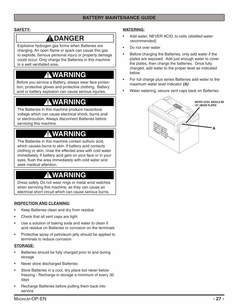
WATERING:
• Add water, NEVER ACID, to cells (distilled water recommended).
• Do not over water
• Before charging the Batteries, only add water if the plates are exposed. Add just enough water to cover the plates, then charge the batteries. Once fully charged, add water to the proper level as indicated below.
• For full charge plus series Batteries add water to the maximum water level indicator (A).
• Water watering, secure vent caps back on Batteries.
WATER LEVEL SHOULD BE 1/8'' ABOVE PLATES
A

- 28 - MAGNUM-OP-EN
MAINTENANCE
DAILY MAINTENANCE:
1. Remove the clean Pads or Brushes. Never use soiled Pads when cleaning. Replace Pads when they become packed with residue.
2. Remove and clean debris from the fl oat shut-off screen and Drain Saver located inside the Recovery Tank.
3. Drain and rinse Tanks thoroughly and fl ush out Solution Feed to deck.
4. Inspect Vacuum Hose for any objects obstructing the air fl ow.
5. Raise Squeegee and wipe Blades with a clean cloth. Store Squeegee in the raise position to prevent damage or setting of the Blades.
6. Wipe down machine if needed. Use a non-abrasive, non-solvent cleaner or a clean damp cloth.
7. Recharge the Batteries if needed.
WEEKLY MAINTENANCE:
1. Check Battery water level in each cell of the Batteries and fi ll as needed. Always use distilled water to refi ll Batteries. Batteries should be fi lled approximately 3⁄4'' to 1'' above the plates. Overfi lling will cause the Batteries to leak during charging. The charging process creates gas bubbles inside the Battery, which effectively increases the volume of the electrolyte.
2. Clean Battery tops to prevent corrosion.
3. Flip Scrubdeck Brushes / Pads.
4. Drain and rinse tanks thoroughly. To thoroughly fl ush out any solution chemicals in solution line valves, refi ll solution tank with a few gallons of warm, clean water and run the machine until tank is empty.
MONTHLY MAINTENANCE:
1. Check Scrubdeck and Squeegee lifting cables for wear and spring tension.
2. Check machine for water leaks and loose nuts and bolts.
3. Check to see if Battery cables are tightened. Tighten,
if needed, 8-10 ft/lb MAX.
4. Grease caster swivel and Squeegee Pivot Point.
YEARLY MAINTENANCE:
Call your local dealer for yearly maintenance.
STORING MACHINE:
1. Be sure to fl ush the Tanks out completely. To thoroughly fl ush out any solution chemicals in solution line and valves, refi ll Solution Tank with a few gallons of warm clean water and run machine until Tank is empty.
2. Open the Recovery Tank lid to promote air circulation.
3. Raise Scrubdeck and Squeegee.
CHECKING BATTERY SPECIFIC GRAVITY:
Use a hydrometer to check the Battery specifi c gravity.Checking Gravity:• Hydrometer• Battery
NOTICEDo not take readings immediately after adding distilled water. If water and acid are not thoroughly mixed, the reading may not be accurate.
Check the hydrometer against this chart
SPECIFIC GRAVITY @ 80°F (27°C)
BATTERY CONDITION
1.265 100% Charged
1.225 75% Charged
1.190 50% Charged
1.155 25% Charged
1.120 Discharged
NOTICEIf the readings are taken when the battery electrolyte is any temperature other than 80°F(27°C), the reading must be temperature corrected. To fi nd the corrected specifi c gravity reading when the temperature of the battery electrolyte is other than 80°F(27°C): add (+) to the specifi c gravity reading 0.004 (4 points), for each 10°F(6°C) above 80°F(27°C). Subtract (-) from the specifi c reading 0.004 (4 points), for each 10°F(6°C) below 80°F(27°C).
WATER LEVEL SHOULD BE 1/8'' ABOVE PLATES

MAGNUM-OP-EN - 29 -
MAGNUM PM RECORDS
CUSTOMER INFORMATION
CUSTOMER EMAIL
ADDRESS PHONE
CITY STATE ZIP CONTACT
MACHINE INFORMATION
MODEL #: SERIAL #:
WORK ORDER#: HOUR METER (Key):
CHASSIS HOUR METER: HOUR METER (Traction):
RE-CHARGE COUNTER: HOUR METER (Scrub):
ISOLATOR HOUR METER: HOUR METER (Vac):
NOTE: Isolators need to be replaced on Scrubber Machines at 1000 Hours or Annually
BATTERY CONDITION CELL 1 CELL 2 CELL 3 CELL 4 CELL 5 CELL 6
BATTERY 1 HYDROMETER
BATTERY 1 ELECTROLYTE CLARITY(Clear, Cloudy, Particulate, Dark)
BATTERY 1 WATER LEVEL(Overfi lled, Full, Low, Dry)
BATTERY 2 HYDROMETER
BATTERY 2 ELECTROLYTE CLARITY(Clear, Cloudy, Particulate, Dark)
BATTERY 2 WATER LEVEL(Overfi lled, Full, Low, Dry)
BATTERY 3 HYDROMETER
BATTERY 3 ELECTROLYTE CLARITY(Clear, Cloudy, Particulate, Dark)
BATTERY 3 WATER LEVEL(Overfi lled, Full, Low, Dry)
BATTERY 4 HYDROMETER
BATTERY 4 ELECTROLYTE CLARITY(Clear, Cloudy, Particulate, Dark)
BATTERY 4 WATER LEVEL(Overfi lled, Full, Low, Dry)
CLEAN BATTERY TOPS. CHECK BATTERY CABLE AND TERMINAL CONDITION.
NOTES:
PAD/BRUSH CONDITION
SCRUB BRUSH FIBER LENGTH ROTATED BRUSHES
BROOM DRIVER SOCKETS (4) GOOD WORN NEEDS REPLACEMENT
DRIVER IDLER HUBS GOOD WORN NEEDS REPLACEMENT
SIDE BROOM CONDITION GOOD WORN NEEDS REPLACEMENT ROTATED SIDE TO SIDE
DISK PAD DRIVER GOOD WORN NEEDS REPLACEMENT
EDGE PAD GRIP FACE GOOD WORN NEEDS REPLACEMENT
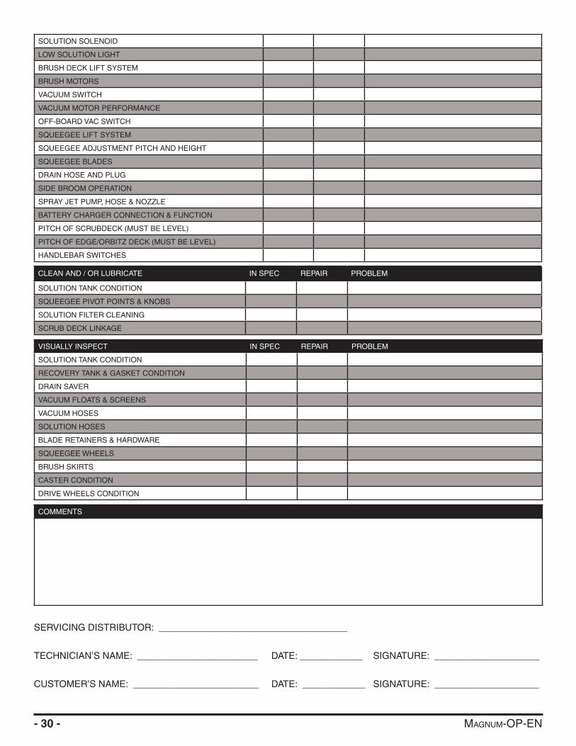
CHECK OPERATION AND CONDITION OF: IN SPEC REPAIR PROBLEM
MAIN POWER SWITCH OR KEY SWITCH
LCD DISPLAY
PAGE BUTTON
BRUSH PRESSURE TOGGLE
MANAGERS LOCK OUT
REVERSE SWITCH
BRUSH SWITCH
SOLUTION +/- SWITCH
- 30 - MAGNUM-OP-EN
SOLUTION SOLENOID
LOW SOLUTION LIGHT
BRUSH DECK LIFT SYSTEM
BRUSH MOTORS
VACUUM SWITCH
VACUUM MOTOR PERFORMANCE
OFF-BOARD VAC SWITCH
SQUEEGEE LIFT SYSTEM
SQUEEGEE ADJUSTMENT PITCH AND HEIGHT
SQUEEGEE BLADES
DRAIN HOSE AND PLUG
SIDE BROOM OPERATION
SPRAY JET PUMP, HOSE & NOZZLE
BATTERY CHARGER CONNECTION & FUNCTION
PITCH OF SCRUBDECK (MUST BE LEVEL)
PITCH OF EDGE/ORBITZ DECK (MUST BE LEVEL)
HANDLEBAR SWITCHES
CLEAN AND / OR LUBRICATE IN SPEC REPAIR PROBLEM
SOLUTION TANK CONDITION
SQUEEGEE PIVOT POINTS & KNOBS
SOLUTION FILTER CLEANING
SCRUB DECK LINKAGE
VISUALLY INSPECT IN SPEC REPAIR PROBLEM
SOLUTION TANK CONDITION
RECOVERY TANK & GASKET CONDITION
DRAIN SAVER
VACUUM FLOATS & SCREENS
VACUUM HOSES
SOLUTION HOSES
BLADE RETAINERS & HARDWARE
SQUEEGEE WHEELS
BRUSH SKIRTS
CASTER CONDITION
DRIVE WHEELS CONDITION
COMMENTS
SERVICING DISTRIBUTOR: ____________________________________
TECHNICIAN’S NAME: _______________________ DATE: ____________ SIGNATURE: ____________________
CUSTOMER’S NAME: ________________________ DATE: ____________ SIGNATURE: ____________________
MAGNUM-OP-EN - 31 -
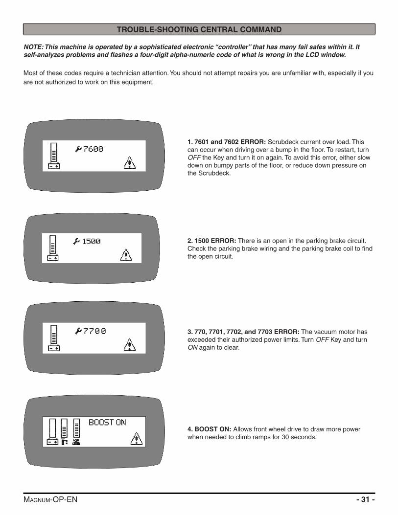
TROUBLE-SHOOTING CENTRAL COMMAND
NOTE: This machine is operated by a sophisticated electronic “controller” that has many fail safes within it. It self-analyzes problems and fl ashes a four-digit alpha-numeric code of what is wrong in the LCD window.
Most of these codes require a technician attention. You should not attempt repairs you are unfamiliar with, especially if you are not authorized to work on this equipment.
1. 7601 and 7602 ERROR: Scrubdeck current over load. This can occur when driving over a bump in the fl oor. To restart, turn OFF the Key and turn it on again. To avoid this error, either slow down on bumpy parts of the fl oor, or reduce down pressure on the Scrubdeck.
2. 1500 ERROR: There is an open in the parking brake circuit. Check the parking brake wiring and the parking brake coil to fi nd the open circuit.
3. 770, 7701, 7702, and 7703 ERROR: The vacuum motor has exceeded their authorized power limits. Turn OFF Key and turn ON again to clear.
4. BOOST ON: Allows front wheel drive to draw more power when needed to climb ramps for 30 seconds.

- 32 - MAGNUM-OP-EN
5. 7700: Vacuum Motor circuit is open.
6. Throttle ERROR: You pressed the foot pedal before turning on the key. Turn OFF the key and try again, leaving foot off of the pedal.
7. 2C00 and 2C01 ERROR: Low voltage warning. Voltage has dropped down below the minimum required to operate the ma-chine. If you wait a few minutes, the Batteries may come up in voltage, allowing you to drive very slowly to the recharge station. If not, you will have to release the parking brake (on the front wheel, pull lever toward the front of the machine to release) and push the machine to recharging station. You must disconnect the traction motor! (+ cable fi rst)
8. 7802 ERROR: The traction motor pulled excessive current perhaps running a ramp for more than the 60 seconds allow-ing for this. Turn OFF the Key, turn on again, and continue. You should not use this machine to climb ramps so steep and so long that this code comes up repeatedly, or you could overheat the traction motor.
9. All other ERROR codes: Turn OFF the Key, and disconnect the positive battery cable from the Batteries for more than one minute (the time is needed to drain the controller on-board capacitor). Reconnect cables, being sure that it is tight. Too loose and you will burn Battery. If you over tighten the cables you can damage the Battery lead terminal. Try again.
10. If the problems cannot be solved by any of this solution, call your local dealer service department.
MAGNUM-OP-EN - 33 -
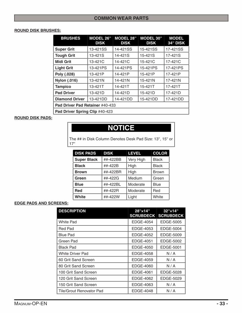
COMMON WEAR PARTS
ROUND DISK BRUSHES:
BRUSHES MODEL 26'' DISK
MODEL 28'' DISK
MODEL 30'' DISK
MODEL 34'' DISK
Super Grit 13-421SS 14-421SS 15-421SS 17-421SS
Tough Grit 13-421S 14-421S 15-421S 17-421S
Midi Grit 13-421C 14-421C 15-421C 17-421C
Light Grit 13-421PS 14-421PS 15-421PS 17-421PS
Poly (.028) 13-421P 14-421P 15-421P 17-421P
Nylon (.016) 13-421N 14-421N 15-421N 17-421N
Tampico 13-421T 14-421T 15-421T 17-421T
Pad Driver 13-421D 14-421D 15-421D 17-421D
Diamond Driver 13-421DD 14-421DD 15-421DD 17-421DD
Pad Driver Pad Retainer #40-433
Pad Driver Spring Clip #40-423
ROUND DISK PADS:
NOTICEThe ## in Disk Column Denotes Desk Pad Size: 13'', 15'' or 17''
DISK PADS DISK LEVEL COLOR
Super Black ##-422BB Very High Black
Black ##-422B High Black
Brown ##-422BR High Brown
Green ##-422G Medium Green
Blue ##-422BL Moderate Blue
Red ##-422R Moderate Red
White ##-422W Light White
EDGE PADS AND SCREENS:
DESCRIPTION 28''×14'' SCRUBDECK
32''×14'' SCRUBDECK
White Pad EDGE-4054 EDGE-5005
Red Pad EDGE-4053 EDGE-5004
Blue Pad EDGE-4052 EDGE-5009
Green Pad EDGE-4051 EDGE-5002
Black Pad EDGE-4050 EDGE-5001
White Driver Pad EDGE-4058 N / A
60 Grit Sand Screen EDGE-4059 N / A
80 Grit Sand Screen EDGE-4060 N / A
100 Grit Sand Screen EDGE-4061 EDGE-5028
120 Grit Sand Screen EDGE-4062 EDGE-5029
150 Grit Sand Screen EDGE-4063 N / A
Tile/Grout Renovator Pad EDGE-4048 N / A

- 34 - MAGNUM-OP-EN
Dominator HD Strip Pad EDGE-4055 N / A
Maroon ECO Prep Pad EDGE-4056 EDGE-5007
Remover Burnishing Pad EDGE-4057 EDGE-5008
Porko Burnishing Pad EDGE-4047 N / A
Velcro Pad 300-4024 N / A
NEW STYLE CYLINDRICAL BRUSHES:
For Machine Serial #50000 & Greater
BRUSHES MODEL 24'' CYLINDRICAL
MODEL 27'' CYLINDRICAL
MODEL 30'' CYLINDRICAL
MODEL 34'' CYLINDRICAL
Super Grit N / A N / A N / A N / A
Tough Grit 225-821S 255-821S 285-821S 325-821S
Midi Grit 225-821C 255-821C 285-821C 325-821C
Light Grit 225-821PS 255-821PS 285-821PS 325-821PS
Poly (.028) N / A N / A N / A N / A
Nylon (.016) 225-821N 255-821N 285-821N 325-821N
OLD STYLE CYLINDRICAL BRUSHES:
For Machines Prior To Serial #50000
BRUSHES MODEL 24'' CYLINDRICAL
MODEL 27'' CYLINDRICAL
MODEL 30'' CYLINDRICAL
MODEL 34'' CYLINDRICAL
Super Grit N / A N / A N / A N / A
Tough Grit 22-521S 25-521S 28-521S 32-521S
Midi Grit 22-521C 25-521C 28-521C 32-521C
Light Grit 22-521PS 25-521PS 28-521PS 32-521PS
Poly (.028) N / A N / A N / A N / A
Nylon (.016) 22-521N 25-521N 28-521N 32-521N
EDGE/ORBITZ GRIP FACE:
DESCRIPTION PART#
28'' Velcro Grip Face 300-1039
28'' Mighty Lok Grip Face 300-01037Z
32'' Mighty Lok Grip Face 300-01037Z
SQUEEGEE BLADE KITS & COMPLETE SQUEEGEE ASSEMBLIES:
SQUEEGEE SIZE
24'' - 28'' DECKS
30'' - 34'' DECKS
32'' Squeegee Optional Optional
35'' Squeegee Standard Optional
38'' Squeegee Optional Standard
SQUEEGEE SIZE
GUM RUBBER BLADE KIT
LINATEX BLADE KIT
URETHANE BLADE KIT
COMPLETE SQUEEGEE
ASSEMBLIES32'' Squeegee 22-770G 22-770L 22-770U 23-7180
35'' Squeegee 25-770G 25-770L 25-770U 25-7180
38'' Squeegee 28-770G 28-770L 28-770U 28-7180

MAGNUM-OP-EN - 35 -
NOTICESqueegee blade kits include (1) Rear Blade, (1) Front Blade, and (2) Backup Wheels with hardware.
NOTICESqueegee Assemblies (complete) listed above all come with Linatex blades.
NOTICESize is stamped into the top of the painted steel squeegee body on all squeegee's.
NOTICEThe 32'' squeegee is designed for narrow aisles and may not have the same water control around tight turns as the large squeegees.

BLANKTHIS PAGE WAS INTENTIONALLY LEFT BLANK

BLANKTHIS PAGE WAS INTENTIONALLY LEFT BLANK

© RPS Corporation 2016
1711 South StreetRacine, WI 53404www.rpscorporation.comwww.factorycat.comwww.tomcatequip.comTel. US: 800-634-4060Tel. Int: (001) 262-681-3583