Embed Size (px)
Citation preview
Operating Instructions
Reactive Power Control Relay RM 2106/12

2
3
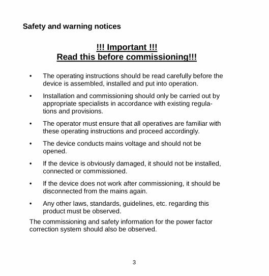
Safety and warning notices
!!! Important !!!
Read this before commissioning!!!
• The operating instructions should be read carefully before the device is assembled, installed and put into operation.
• Installation and commissioning should only be carried out by appropriate specialists in accordance with existing regula-tions and provisions.
• The operator must ensure that all operatives are familiar with these operating instructions and proceed accordingly.
• The device conducts mains voltage and should not be opened.
• If the device is obviously damaged, it should not be installed, connected or commissioned.
• If the device does not work after commissioning, it should be disconnected from the mains again.
• Any other laws, standards, guidelines, etc. regarding this product must be observed.
The commissioning and safety information for the power factor correction system should also be observed.
4
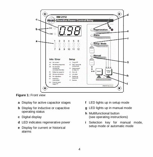
Figure 1: Front view
a Display for active capacitor stages
b Display for inductive or capacitive operating status
c Digital display
d LED indicates regenerative power
e Display for current or historical alarms
f LED lights up in setup mode
g LED lights up in manual mode
h Multifunctional button (see operating instructions)
i Selection key for manual mode, setup mode or automatic mode

5
Figure 2: Rear view
j Connection for the current trans-former
k Optional connector for improved measurement of harmonic wave
l Connector for power supply to the control relay
m Connectors for the control contacts that switch the contactors. The shared pole is connected to terminal ´L´.
n Typical connection

6
Contents Page Page
1. Introduction .................................7 1.1 How to use
these operating instructions ...........7 1.2 Scope of functions .........................7
2. Installation and connection.........8 2.1 Installation .....................................8 2.2 Voltage connection ........................8 2.3 Current transformer connection .....8 2.4 ”Meas” measuring
voltage connection.........................9 2.5 Switching contacts.........................9 2.6 Alarm contact ................................9 2.7 Standard connection....................10 2.8 Extended connection ...................11 2.9 Connection with
voltage transformer......................12 2.10 Connection in special cases ........13
3. Start-up ......................................14 3.1 Initial start-up...............................14 3.2 Subsequent start-up ....................15
4. Control relay setup ....................16 4.1 Target power factor setting ..-1- ...17 4.2 Overcurrent switch off .......... -2- ...19 4.3 Relay 6 as alarm relay ......... -3- ...19 4.4 Automatic response
current identification............. -4- ...20 4.5 Response current ................ -5- ...20 4.6 Relative value
of the switch outputs ............ -6- ...22 4.7 Service ................................ -7- ...22
5. Functioning and operation....... 23 5.1 Automatic control mode .............. 23 5.2 Displaying the
total harmonic distortion factor .... 23 5.3 Check System ............................ 23 5.4 Manual mode.............................. 24
6. Alarms and troubleshooting .... 25 6.1 Connection errors ....................... 25 6.1.1 E3 - No capacitors ................. 25 6.1.2 E1 - Defect capacitor stages .. 25 6.1.3 E2 - Incorrect connection ....... 25 6.1.4 I = 0 - No current in current path25 6.2 Connection messages ................ 26 6.2.1 A2 - Incorrect connection
that can be corrected internally......................... 26
6.2.2 A1 - Relative value of the switch output .................. 26
6.3 Alarms in automatic control operation .................................... 26
6.3.1 E4 - Harmonic overcurrent in the capacitor ............... 26
6.3.2 E5 - Target power factor not reached .................... 27
6.3.3 E1 - Defect capacitor stages .. 27 6.3.4 U = 0 - No measuring voltage..... 27 6.3.5 I = 0 - No measuring current ..... 27 6.4 Other errors ................................ 27 6.5 Troubleshooting .......................... 28
7. Technical data........................... 29

7
1. Introduction
The reactive power control relay RM 2112 and RM 2106 respectively is capa-ble of measuring the reactive power and active power of the connected mains network. Working in conjunction with a power factor correction system, the de-vice controls the programmed target power factor by activating or deactivating capacitors. 1.1 How to use these operating in-
structions
Important: It is essential that you read section 2 “Installation and connection” and section 3 „Start-up“ before installing the control relay. The functions of the control relay are also described in brief in section 1.2 „Scope of functions“ .
The setting options for the control relay are described in section 4 „Control re-lay setup” .
Section 5 „Functioning and operation“ explains how the control relay works and how to operate it. Section 6 „Alarms and troubleshoot-ing“ describes alarms and error mes-sages of the control relay. Troubleshooting information is also provided there.
1.2 Scope of functions
Below is a brief overview of the various functions of the device:
• 12 switching contacts at RM 2112 and 6 switching contacts at RM 2106
• Power factor display
• Total harmonic distortion factor display (voltage thd)
• Semi-automatic connection detection
• Automatic detection of the capacitor stages
• Comprehensive connection analysis
• Patented characteristic avoiding over-compensation for low active power
• Four-quadrant regulation
• Cyclic switching of all capacitor stages of the same capacity
• Reactive power requirement-dependent switching delay time
• Optional monitoring of the harmonic overcurrent in the capacitor
• Deactivation at zero voltage or zero current
• Alarm signals for: - failure to reach the target power fac-tor - overcurrent in the capacitor - defects at capacitor stages

8
2. Installation and connection
The reactive power control relay RM 2112 and RM 2106 respectively can be connected in a number of different ways. The main connection methods are described below.
Important information: The control relay should be discon-nected from the mains during installation. 2.1 Installation
The reactive power control relay is in-stalled from the front in a control panel space measuring 138 x 138mm and is fixed in place using the mounting screws of the front panel. As accessories (protection kit; see section 8) insulated fixing screws are available. These can be used to install the control relay into switchgear cabinets and cubicles of protective class II. Also a sealing ring is part of the protection kit, which must be used when installing the control relay in switchgear cabinets and cubicles of protection class IP 54.
The pre-assembled fixing clamps ensure speedy and secure assembly. The elec-trical connection is created by means of plug-in connectors which are also in-cluded in the delivery.
2.2 Voltage connection
Reactive power control relay obtains its voltage supply via terminals ”L” and ”N” (see figure 2, item ’l’).
A phase conductor is to be connected to terminal ”L” and neutral conductor to ter-minal ”N”. For advanced connection variations see sections 2.7 to 2.10.
Important information: The reactive power control relay is designed for voltage supplies of up to 240VAC.
The connections for the supply volt-age are to be fused externally with 4A max.
In the case of mains networks that do not facilitate voltage tapping in the 220VAC to 240VAC range (either phase/phase or phase/neutral), a voltage transformer must be used for the power supply for the control relay. (See section 2.9 )
2.3 Current transformer connection
Outputs S1 and S2 of the current trans-former are connected to terminals S1 and S2 (Figure 2, item ’j’) of the control relay. To keep the load of the current trans-former as low as possible, the feed lines should have a adequate cross section.
9
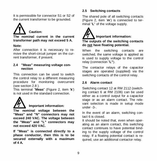
It is permissible for connector S1 or S2 of the current transformer to be grounded.
Caution: The nominal current in the current transformer path may not exceed 5 A.
Note: After connection it is necessary to re-move the short-circuit jumper on the cur-rent transformer, if present. 2.4 ”Meas” measuring voltage con-
nection
This connection can be used to switch the control relay to a different measuring procedure for monitoring overcurrent (see section 2.8 ). This terminal ”Meas” (Figure 2, item ’k’) is not used in the standard connection.
Important information: The nominal voltage between the ”Meas” and ”N” connectors may not exceed 240 VAC. The voltage between the ”Meas” and ”L” connectors may not exceed 420 VAC.
If ”Meas” is connected directly to a phase conductor, then this is to be secured externally with a maximum of 4 A.
2.5 Switching contacts
The shared pole of all switching contacts (Figure 2, item ’m’) is connected to ter-minal ”L” of the voltage supply.
Important information: The outputs of the switching contacts do not have floating potential.
When the switching contacts are switched, the same voltage is applied as is used to supply voltage to the control relay (connection ”L” ).
The contactor relays of the capacitor stages are operated (supplied) via the switching contacts of the control relay. 2.6 Alarm contact
Switching contact 12 at RM 2112 (switch-ing contact 6 at RM 2106) can be used either as a control output for a capacitor stage or as an alarm contact. The rele-vant selection is made in setup mode under -3-.
In the event of an alarm, switching con-tact 6 is closed. It should be noted that, even when oper-ating as an alarm contact, this switching contact continues to have potential bind-ing to the supply voltage of the control relay. If a floating potential contact is re-quired, use an additional contactor relay.

10
Figure 3: Single phase connection
2.7 Single phase connection
The connection diagram above shows the same connection as the one printed on the back of the control relay.
The voltage signal for power factor meas-urement is received in parallel with the voltage supply. The terminal ”Meas” is not in use.
In this connection variant, only the 5th, 7th, 11th and 13th harmonics of the volt-age are used to calculate the harmonic overcurrent in the capacitor.
This connection variant can be chosen if the above-mentioned harmonics are suf-ficient for monitoring overcurrent or if overcurrent monitoring has been com-pletely switched off (setup code -2-). (see section 4.2)
Current transformer and terminal ”L” should be attached to the same phase conductor: Either L1, L2 or L3.
RM2112 / 06
11
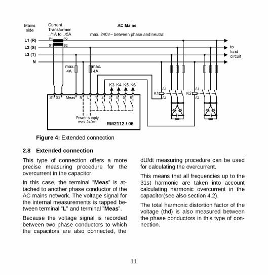
Figure 4: Extended connection
2.8 Extended connection
This type of connection offers a more precise measuring procedure for the overcurrent in the capacitor.
In this case, the terminal ”Meas” is at-tached to another phase conductor of the AC mains network. The voltage signal for the internal measurements is tapped be-tween terminal ”L” and terminal ”Meas”.
Because the voltage signal is recorded between two phase conductors to which the capacitors are also connected, the
dU/dt measuring procedure can be used for calculating the overcurrent.
This means that all frequencies up to the 31st harmonic are taken into account calculating harmonic overcurrent in the capacitor(see also section 4.2).
The total harmonic distortion factor of the voltage (thd) is also measured between the phase conductors in this type of con-nection.
RM2112 / 06
12
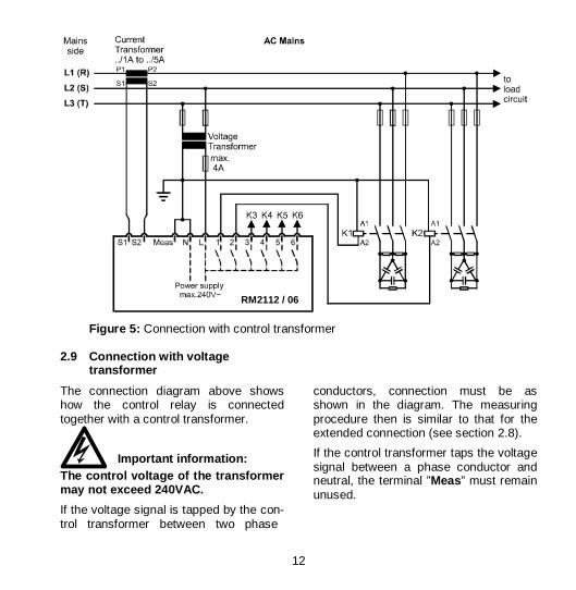
Figure 5: Connection with control transformer
2.9 Connection with voltage
transformer
The connection diagram above shows how the control relay is connected together with a control transformer.
Important information: The control voltage of the transformer may not exceed 240VAC.
If the voltage signal is tapped by the con-trol transformer between two phase
conductors, connection must be as shown in the diagram. The measuring procedure then is similar to that for the extended connection (see section 2.8).
If the control transformer taps the voltage signal between a phase conductor and neutral, the terminal ”Meas” must remain unused.
RM2112 / 06
13
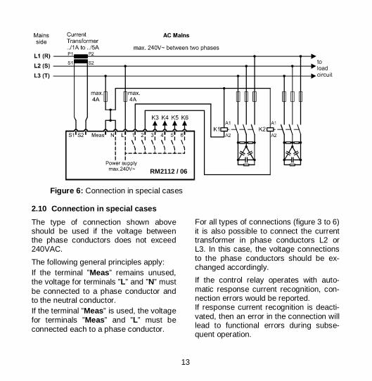
Figure 6: Connection in special cases
2.10 Connection in special cases
The type of connection shown above should be used if the voltage between the phase conductors does not exceed 240VAC.
The following general principles apply: If the terminal ”Meas” remains unused, the voltage for terminals ”L” and ”N” must be connected to a phase conductor and to the neutral conductor. If the terminal ”Meas” is used, the voltage for terminals ”Meas” and ”L” must be connected each to a phase conductor.
For all types of connections (figure 3 to 6) it is also possible to connect the current transformer in phase conductors L2 or L3. In this case, the voltage connections to the phase conductors should be ex-changed accordingly.
If the control relay operates with auto-matic response current recognition, con-nection errors would be reported. If response current recognition is deacti-vated, then an error in the connection will lead to functional errors during subse-quent operation.
RM2112 / 06
14
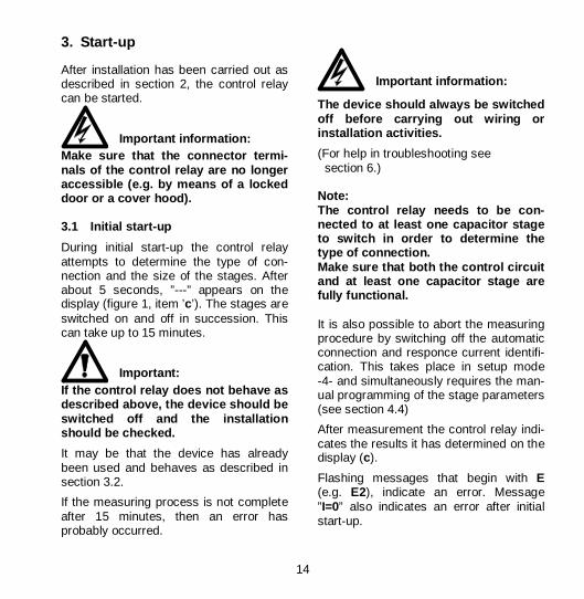
3. Start-up
After installation has been carried out as described in section 2, the control relay can be started.
Important information: Make sure that the connector termi-nals of the control relay are no longer accessible (e.g. by means of a locked door or a cover hood). 3.1 Initial start-up
During initial start-up the control relay attempts to determine the type of con-nection and the size of the stages. After about 5 seconds, ”---” appears on the display (figure 1, item ’c’). The stages are switched on and off in succession. This can take up to 15 minutes.
Important: If the control relay does not behave as described above, the device should be switched off and the installation should be checked.
It may be that the device has already been used and behaves as described in section 3.2.
If the measuring process is not complete after 15 minutes, then an error has probably occurred.
Important information: The device should always be switched off before carrying out wiring or installation activities.
(For help in troubleshooting see section 6.) Note: The control relay needs to be con-nected to at least one capacitor stage to switch in order to determine the type of connection. Make sure that both the control circuit and at least one capacitor stage are fully functional. It is also possible to abort the measuring procedure by switching off the automatic connection and responce current identifi-cation. This takes place in setup mode -4- and simultaneously requires the man-ual programming of the stage parameters (see section 4.4)
After measurement the control relay indi-cates the results it has determined on the display (c).
Flashing messages that begin with E (e.g. E2), indicate an error. Message ”I=0” also indicates an error after initial start-up.
15
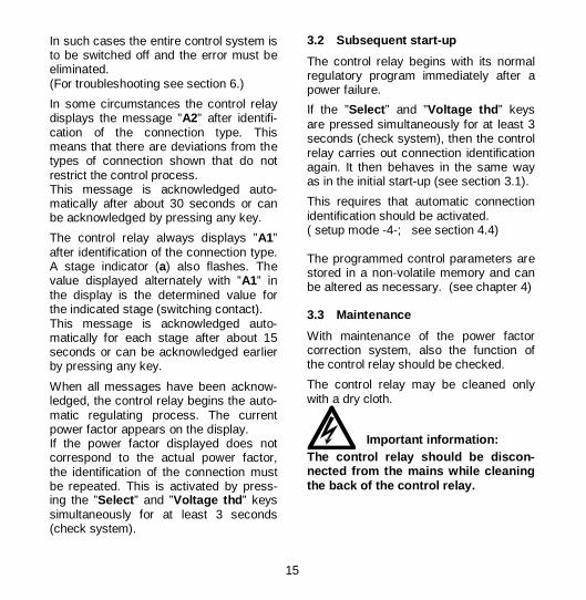
In such cases the entire control system is to be switched off and the error must be eliminated. (For troubleshooting see section 6.)
In some circumstances the control relay displays the message ”A2” after identifi-cation of the connection type. This means that there are deviations from the types of connection shown that do not restrict the control process. This message is acknowledged auto-matically after about 30 seconds or can be acknowledged by pressing any key.
The control relay always displays ”A1” after identification of the connection type. A stage indicator (a) also flashes. The value displayed alternately with ”A1” in the display is the determined value for the indicated stage (switching contact). This message is acknowledged auto-matically for each stage after about 15 seconds or can be acknowledged earlier by pressing any key.
When all messages have been acknow-ledged, the control relay begins the auto-matic regulating process. The current power factor appears on the display. If the power factor displayed does not correspond to the actual power factor, the identification of the connection must be repeated. This is activated by press-ing the ”Select ” and ”Voltage thd ” keys simultaneously for at least 3 seconds (check system).
3.2 Subsequent start-up
The control relay begins with its normal regulatory program immediately after a power failure.
If the ”Select ” and ”Voltage thd ” keys are pressed simultaneously for at least 3 seconds (check system), then the control relay carries out connection identification again. It then behaves in the same way as in the initial start-up (see section 3.1).
This requires that automatic connection identification should be activated. ( setup mode -4-; see section 4.4) The programmed control parameters are stored in a non-volatile memory and can be altered as necessary. (see chapter 4) 3.3 Maintenance
With maintenance of the power factor correction system, also the function of the control relay should be checked.
The control relay may be cleaned only with a dry cloth.
Important information: The control relay should be discon-nected from the mains while cleaning the back of the control relay.
16
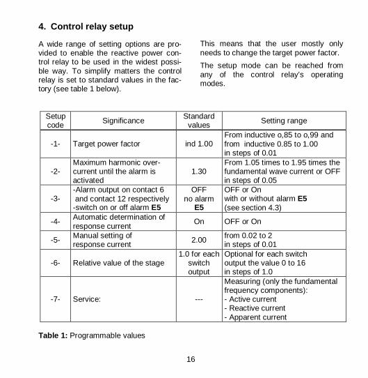
4. Control relay setup
A wide range of setting options are pro-vided to enable the reactive power con-trol relay to be used in the widest possi-ble way. To simplify matters the control relay is set to standard values in the fac-tory (see table 1 below).
This means that the user mostly only needs to change the target power factor.
The setup mode can be reached from any of the control relay’s operating modes.
Setup code Significance Standard
values Setting range
-1- Target power factor ind 1.00 From inductive o,85 to o,99 and from inductive 0.85 to 1.00 in steps of 0.01
-2- Maximum harmonic over-current until the alarm is activated
1.30 From 1.05 times to 1.95 times the fundamental wave current or OFF in steps of 0.05
-3- -Alarm output on contact 6 and contact 12 respectively -switch on or off alarm E5
OFF no alarm
E5
OFF or On with or without alarm E5 (see section 4.3)
-4- Automatic determination of response current
On OFF or On
-5- Manual setting of response current 2.00 from 0.02 to 2
in steps of 0.01
-6- Relative value of the stage 1.0 for each
switch output
Optional for each switch output the value 0 to 16 in steps of 1.0
-7- Service: ---
Measuring (only the fundamental frequency components): - Active current - Reactive current - Apparent current
Table 1: Programmable values
17
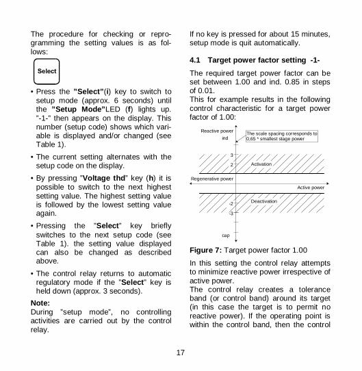
The procedure for checking or repro-gramming the setting values is as fol-lows:
• Press the ”Select” (i) key to switch to
setup mode (approx. 6 seconds) until the ”Setup Mode” LED (f) lights up. ”-1-” then appears on the display. This number (setup code) shows which vari-able is displayed and/or changed (see Table 1).
• The current setting alternates with the setup code on the display.
• By pressing ”Voltage thd ” key (h) it is possible to switch to the next highest setting value. The highest setting value is followed by the lowest setting value again.
• Pressing the ”Select ” key briefly switches to the next setup code (see Table 1). the setting value displayed can also be changed as described above.
• The control relay returns to automatic regulatory mode if the ”Select ” key is held down (approx. 3 seconds).
Note: During ”setup mode”, no controlling activities are carried out by the control relay.
If no key is pressed for about 15 minutes, setup mode is quit automatically. 4.1 Target power factor setting -1-
The required target power factor can be set between 1.00 and ind. 0.85 in steps of 0.01. This for example results in the following control characteristic for a target power factor of 1.00:
Active power
Reactive power
2
3
-2
-3
ind
cap
Regenerative power
Activation
Deactivation
The scale spacing corresponds to0,65 * smallest stage power
Figure 7: Target power factor 1.00
In this setting the control relay attempts to minimize reactive power irrespective of active power. The control relay creates a tolerance band (or control band) around its target (in this case the target is to permit no reactive power). If the operating point is within the control band, then the control

18
relay will not carry out any further switching. For a target power factor of 1.00 this means that the permitted reactive power may not exceed 0.65 times the lowest capacitor stage.
If, on the other hand, the work point is outside of the control band, the control relay will attempt to reach the control band with the smallest possible number of switchings by means of specific activa-tion and deactivation procedures.
3
Reactive power
4
-1
ind
cap
Regenerative power
Activation
Deactivation
The scale spacing corresponds to0,65 * smallest stage power
Active power
-2
-3
Figure 8: Target power factor 0.92
In addition to the target power factor set-ting 1.00, the control relay can also be set to a target power factor between 0.85 and 0.99. A distinction is made here be-tween two different control bands. The control bands are distinguished by a
large or small zero preceding the decimal point in the target power factor input.
The type of control band shown in figure 8 can be achieved by means of a large zero preceding the decimal point of the target power factor setting. The target power factor forms the upper limit of the control band. The control relay always attempts to obtain a better power factor. However, the control band levels off at low values of active power in order to avoid overcompensation.
For regenerative power (active power supplied to the mains) the control band stays leveled off for regenerative power.
1
Reactive power
2
-2-3
ind
cap
Regenerative power
Activation
Deactivation
The scale spacing corresponds to0,65 * smallest stage power
Active power
Figure 9: Target power factor o.92
19
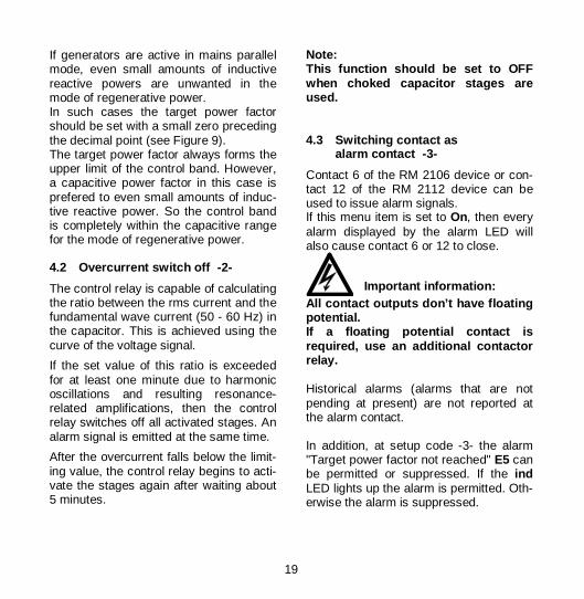
If generators are active in mains parallel mode, even small amounts of inductive reactive powers are unwanted in the mode of regenerative power. In such cases the target power factor should be set with a small zero preceding the decimal point (see Figure 9). The target power factor always forms the upper limit of the control band. However, a capacitive power factor in this case is prefered to even small amounts of induc-tive reactive power. So the control band is completely within the capacitive range for the mode of regenerative power. 4.2 Overcurrent switch off -2-
The control relay is capable of calculating the ratio between the rms current and the fundamental wave current (50 - 60 Hz) in the capacitor. This is achieved using the curve of the voltage signal.
If the set value of this ratio is exceeded for at least one minute due to harmonic oscillations and resulting resonance-related amplifications, then the control relay switches off all activated stages. An alarm signal is emitted at the same time.
After the overcurrent falls below the limit-ing value, the control relay begins to acti-vate the stages again after waiting about 5 minutes.
Note: This function should be set to OFF when choked capacitor stages are used. 4.3 Switching contact as
alarm contact -3-
Contact 6 of the RM 2106 device or con-tact 12 of the RM 2112 device can be used to issue alarm signals. If this menu item is set to On, then every alarm displayed by the alarm LED will also cause contact 6 or 12 to close.
Important information: All contact outputs don’t have floating potential. If a floating potential contact is required, use an additional contactor relay. Historical alarms (alarms that are not pending at present) are not reported at the alarm contact. In addition, at setup code -3- the alarm "Target power factor not reached" E5 can be permitted or suppressed. If the ind LED lights up the alarm is permitted. Oth-erwise the alarm is suppressed.

20
4.4 Automatic response current identification -4-
If set to On the control relay operates with the response current determined at initial start-up and the values determined for the switch outputs. These values can be read under points -5- and -6- . If set to Off the response current (setup code -5-) and the value of the switch outputs (-6-) must be programmed manu-ally.
This setting is to be selected if the low voltage network is fed by several trans-formers switched in parallel.
Important: If ”OFF” is set, connection must be as shown in connection diagrams 3, 4, 5 or 6. Deviations are not signalled and are not corrected automatically. 4.5 Response current -5-
The response current describes the width of the control band (see figures 7 to 9). The greater the value, the broader the control band.
When automatic response current identi-fication is switched on (-4-), the response current is adapted to the connected power factor correction system to opti-mum effect. The response current
determined can be read under setup code -5- but cannot be altered.
When automatic response current identi-fication is switched off (-4-), the response current can be set between 0.02 and 2 A in steps of 0.01 A.
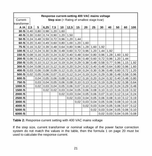
The correct setting for 400 VAC mains voltage and current transformer with 5 A∼ secondary voltage can be found in Table 2.
For other mains currents or current transformers with unlisted primary or secondary current, the response current can be calculated according to the following formula: Formula 1:
IQ V k
U kV
Q k
U kA
u
i
u
i
= ⋅⋅ ⋅
⋅ ⋅≈ ⋅
⋅⋅
0 65400
3150
2 2,
IA = Response current to be set in A Q = Capacitor stage rating of the lowest
stage in var (not the overall power of the system)
U = Mains voltage in V (phase to phase) ki= Current transformer ratio
(primary/ secondary current) ku= Voltage transformer ratio
(primary/ secondary voltage) (if any)
21
Response current-setting 400 VAC mains voltage Current- Step size (= Rating of smallest stage kvar)
transformer A /A 2,5 5 6,25 7,5 10 12,5 15 20 25 30 40 50 60 100 30 /5 0,40 0,80 0,98 1,20 1,60 40 /5 0,30 0,60 0,74 0,90 1,20 1,50 50 /5 0,24 0,48 0,59 0,72 0,96 1,20 1,44 60 /5 0,20 0,40 0,49 0,60 0,80 1,00 1,20 1,60 75 /5 0,16 0,32 0,39 0,48 0,64 0,80 0,96 1,28 1,60 1,92
100 /5 0,12 0,24 0,30 0,36 0,48 0,60 0,72 0,96 1,20 1,44 1,92 150 /5 0,08 0,16 0,20 0,24 0,32 0,40 0,48 0,64 0,80 0,96 1,28 1,60 1,92 200 /5 0,06 0,12 0,15 0,18 0,24 0,30 0,36 0,48 0,60 0,72 0,96 1,20 1,44 250 /5 0,05 0,10 0,12 0,14 0,19 0,24 0,29 0,38 0,48 0,58 0,77 0,96 1,15 1,92 300 /5 0,04 0,08 0,10 0,12 0,16 0,20 0,24 0,32 0,40 0,48 0,64 0,80 0,96 1,60 400 /5 0,03 0,06 0,08 0,09 0,12 0,15 0,18 0,24 0,30 0,36 0,48 0,60 0,72 1,20 500 /5 0,02 0,05 0,06 0,07 0,10 0,12 0,14 0,19 0,24 0,29 0,38 0,48 0,58 0,96 600 /5 0,04 0,05 0,06 0,08 0,10 0,12 0,16 0,20 0,24 0,32 0,40 0,48 0,80 750 /5 0,03 0,04 0,05 0,06 0,08 0,10 0,13 0,16 0,19 0,26 0,32 0,38 0,64
1000 /5 0,02 0,03 0,04 0,05 0,06 0,07 0,10 0,12 0,14 0,19 0,24 0,29 0,48 1500 /5 0,02 0,02 0,03 0,04 0,05 0,06 0,08 0,10 0,13 0,16 0,19 0,32 2000 /5 0,02 0,03 0,04 0,05 0,06 0,07 0,10 0,12 0,14 0,24 2500 /5 0,02 0,03 0,04 0,05 0,06 0,08 0,10 0,12 0,19 3000 /5 0,02 0,03 0,04 0,05 0,06 0,08 0,10 0,16 4000 /5 0,02 0,03 0,04 0,05 0,06 0,07 0,12 5000 /5 0,02 0,03 0,04 0,05 0,06 0,10 6000 /5 0,02 0,03 0,04 0,05 0,08
Table 2: Response current setting with 400 VAC mains voltage
If the step size, current transformer or nominal voltage of the power factor correction system do not match the values in the table, then the formula 1 on page 20 must be used to calculate the response current.

22
4.6 Relative value of the switch outputs -6-
These values refer to the relative stage ratings.
Example: A system has the following stages: Stage rating Relative value 6.2 kvar => 1.0 6.2 kvar => 1.0 12.5 kvar => 2.0 25 kvar => 4.0 25 kvar => 4.0 0 kvar => 0.0
Note: To assure correct operation of the reac-tive VA control system the following con-ditions must be taken into account when choosing stage ratings: If all possible switching combinations are sorted according to reactive power (ca-pacity), then the power difference be-tween two consecutive combinations may not be more than 1.2 times the smallest stage power.
When automatic response current identi-fication is switched on (-4-), the relative value is automatically determined by the control relay. This can be read under setup code -6- but not altered.
When automatic response current identi-fication is switched off (-4-), the relative value of the switch outputs must be pro-grammed manually.
The flashing LED in the stage display (a) indicate the switch output to which the relative value refers. Pressing the ”Se-lect ”key (i) briefly allows you to skip to the next relative value. The switch outputs with the lowest ca-pacity are assigned relative value 1.0. The relative values for the bigger stages are calculated as follows:
Formula 2:
Relative valueStage power
Smallest stage power=
Free switch outputs are assigned relative value 0.0. Only whole numbers can be entered as factors. 4.7 Service -7-
The fundamental wave currents presently flowing in the current path (j) of the con-trol relay and be displayed under this point. The display for inductive or capacitive operating status (b) can be used to de-termine which current is displayed.
ind. and cap. off => active current ind. or cap. off => reactive current ind. and cap. on => apparent current
23
5. Functioning and operation
The control relay runs completely auto-matically after it has been connected and started. The current power factor appears in the digital display (c). The ind and cap LEDs (b) show whether the network is loaded with capacitive or inductive reac-tive power. At the same time, the stage indicator (a) shows the switched capacitor stages. 5.1 Automatic control mode
In automatic control mode the control relay constantly measures the current power factor in the network and com-pares this with the target power factor. If deviations are identified that are in ex-cess of the tolerance range (control band), the required target power factor is restored by activating or deactivating specific capacitor stages within the con-trol relay delay time and in accordance with the capacitor discharge time. The control relay delay time is adapted to the size of the deviation. The greater the deviation, the shorter the reaction time. In contrast, the capacitor discharge time is fixed at one minute.
In addition, the control relay monitors the overcurrent in the capacitors and checks whether the connected capacitor power is sufficient for compensation. If auto-maticresponse current identification is
activated, the control relay also checks the power of the capacitors connected.
The control relay issues an alarm in the event of an error. (see section 6) 5.2 Displaying the total harmonic dis-
tortion factor
If the control relay is in automatic control relay mode and if no historical or current alarm is pending, then pressing the ”Volt-age thd ” key (h) will display the current total harmonic distortion factor (thd) of the voltage in %. 5.3 Check System
Simultaneously pressing ”Voltage thd ”(h) and ”Select ”(i) displays the cur-rent relative value of stage 1. The value displayed alternately with ”A1” in the dis-play (see section 6.2.2). It is acknowl-edged automatically for each stage after about 15 seconds or can be acknowl-edged earlier by pressing any key.
Simultaneously pressing ”Voltage thd ”(h) and ”Select ”(i) for about 3 sec-onds brings the control relay into check system mode. If automatic response current identifica-tion (setup code -4-) is activated, then the control relay behaves as described in section 3.1 „Initial start-up“ .
24
Note: The check system mode defines the present stage ratings as reference val-ues for subsequent stage rating checking.
(see section 3)
5.4 Manual mode
Pressing ”Select ” (i) for more than 3 sec-onds switches the control relay to manual mode. The ”Manual Mode ” LED (g) lights up.
The ”Voltage thd ” key (h) can now be used to select a switching output. The flashing LED in the stage indicator (a) shows which switching output is pres-ently selected. After a waiting period of about 10 sec-onds the switching status of the selected switch output is inverted. After switching the control relay remains in manual mode.
To quit manual mode, press the ”Select ” key (i) for over 6 seconds until neither the ”Manual Mode ” LED (g) nor the ”Setup Mode” LED (f) lights up.
Note: No automatic switching activities are carried out in manual mode. Manual mode does not terminate automati-cally.
Alarm signals E4 and E5 are also gener-ated in manual mode, but do not lead to any switching activities.
An exception to this is the alarm contact when alarm output is activated on contact 6 of the RM 2106 device or contact 12 of the RM 2112 device (setup code -3-).
25
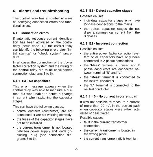
6. Alarms and troubleshooting
The control relay has a number of ways of identifying connection errors and func-tional errors. 6.1 Connection errors
If automatic response current identifica-tion has been activated on the control relay (setup code -4-), the control relay can identify the following errors after ”ini-tial start-up” or ”check system” proce-dure.
In all cases the connection of the power factor correction system and the wiring of the control relay are to be checked(see connection diagrams 3 to 6). 6.1.1 E3 - No capacitors
This error message appears when the control relay was able to measure a cur-rent, but was unable to detect a change in current when switching the capacitor stages.
This can have the following causes: • control contacts (contactors) are not
connected or are not working correctly • the fuses of the capacitor stages have
not been installed • the current transformer is not located
between power supply and loads (in-cluding PFC) (see connection dia-grams 3 to 6).
6.1.2 E1 - Defect capacitor stages
Possible causes: • individual capacitor stages only have
2-phase connections to the mains • the defect capacitor stages do not
draw a symmetrical current from the 3 phases
6.1.3 E2 - Incorrect connection
Possible causes: • the entire power factor correction sys-
tem or all capacitors have only been connected in 2-phase connections
• the ”Meas” terminal is unused and 2 phase conductors are connected be-tween terminal ”N” and ”L”
• the ”Meas” terminal is connected to the neutral conductor
• the ”L” terminal is connected to the neutral conductor
6.1.4 I = 0 - No current in current path
It was not possible to measure a current of more than 20 mA in the current path when capacitor stages were either acti-vated or deactivated. Possible causes: • fault in the current transformer
connection • the current transformer is located in
the wrong place • the current transformer ratio is too high

26
6.2 Connection messages
In addition to the error messages, the control relay also displays the results of its automatic connection recognition. Messages A1 and A2 can be acknowl-edged by pressing any key or are auto-matically acknowledged after a waiting period of about 30 seconds. 6.2.1 A2 - Incorrect connection that
can be corrected internally
The connection has not been made in accordance with connection diagrams 3 to 6. However, the problem has been recognised as a simple confusion in the phase conductors or in the connection of the current transformer. The control relay can continue to operate with this connection. 6.2.2 A1 - Relative value of the
switch output
The value for the relevant switch output is displayed while message A1 appears on the display. Switch outputs at which little or no capacitor rating has been recognised are assigned switching sequence factor 0.0. The user should check whether the values displayed cor-respond to the connected capacitor stage. The connection must be checked if deviations are extreme. The switching sequence determined is also stored in the setup mode (-6-).
6.3 Alarms in automatic control operation
The ”Alarm ” LED (e) lights up for as long as an alarm is active. If alarm output was activated on contact 6 of the RM 2106 device or contact 12 of the RM 2112 device (setup code -3-), this contact also closes. If the alarm status has ended, the ”Alarm ” LED turns off and the alarm con-tact opens again if in use. The message continues to flash on the display. Press-ing the ”Voltage thd ” key (h) enables the cause of the alarm to be read out and the alarm to be acknowledged during or after the alarm . 6.3.1 E4 - Harmonic overcurrent in
the capacitor
The control relay issues this alarm if the programmed limiting value for the ”har-monic overcurrent” (setup code -2-) is exceeded for more than 1 minute. All ac-tivated capacitor stages are deactivated.
After the overcurrent falls below the limit-ing value, the control relay begins to acti-vate the stages again after waiting about 5 minutes. The maximum overcurrent factor (Ieff./I50/60Hz) is recorded as the cause of the alarm.
27
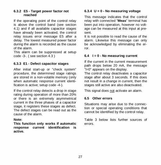
6.3.2 E5 - Target power factor not reached
If the operating point of the control relay is above the control band (see section 4.1) and if all available capacitor stages have already been activated, the control relay issues error message E5 after a delay. The lowest measured power factor during the alarm is recorded as the cause of the alarm. This alarm can be suppressed at setup code -3-. ( see section 4.3 ) 6.3.3 E1 - Defect capacitor stages
After initial start-up or ”check system” procedure, the determined stage ratings are stored in a non-volatile memory (only when automatic response current identi-fication is active; setup code -4-).
If the control relay detects a drop in stage rating during operation of more than 20% or there is an extremely asymmetrical current in the three phases of a capacitor stage, it registers these stages as defect. The defect stages can be read out as the cause of the alarm.
Note: This function only works if automatic response current identification is active.
6.3.4 U = 0 - No measuring voltage
This message indicates that the control relay with connected ”Meas” terminal has been put into operation, however no volt-age can be measured at this input at pre-sent. It is not possible to read the cause of the alarm. Likewise this message can only be acknowledged by eliminating the er-ror. 6.4 I = 0 - No measuring current
If the current in the current measurement path drops below 20 mA, the message ”I=0” appears on the display. The control relay deactivates a capacitor stage after about 3 seconds. If this does not result in a change in current, then the stages still active are also deactivated.
This signal does not activate an alarm. 6.5 Other errors
Situations may arise due to the connec-tion or special operating conditions that cannot be identified by the control relay. Table 3 below lists further sources of errors.

28
7. Troubleshooting
Pos Fault Possible causes Necessary action 1 Control relay not work-
ing; no displays on the front of the control relay.
No or the wrong voltage has been applied to the control relay.
Check that operating voltage applied to the control relay is at the right level.
2 The control relay does not react to manual switching despite
Delay time of about 10 seconds is not up.
If the required stage flashes in the stage display (a) then wait until the stage switches.
availability of power and functioning indicators.
Manual mode is not activated.
Hold down "Select" key until "Manual Mode " LED (g) lights up.
3 Stage indicator (a) lights up, however capacitor contactors are not
Control circuit not connected correctly or no control voltage.
Check the control circuit in accor-dance with the connection dia-gram; check fuse.
switched on. No zero conductor at contactors.
4 Control relay does not terminate the automatic measuring procedure.
Unstable mains supply (strong power factor variation).
Wait for more stable mains condi-tions or enter the response cur-rent and switching sequence manually.
5 One stage is continu-ously activated and de-activated in automatic
Response current set too low.
Set the response current correctly in accordance with Table 1 or Formula 1.
control relay mode. Strong load variation. 6 No stage activation in
automatic control relay mode despite inductive
The response current has been programmed incorrectly.
Set the response current correctly in accordance with Table 1 or Formula 1.
load. Response current not correctly identified despite automatic response current identification being set.
Check the control circuit accord-ing to the connection diagram and repeat the check system procedure
Another measuring device switched in parallel with the control relay current path.
Current paths for different meas-uring devices should always be switched in series
Step size of capacitor is too large.
Introduce capacitors with smaller step size.
Table 3: Notes on troubleshooting

29
Pos Fault Possible causes Necessary action 7 "I=0" flashes on the
display. Current transformer line interrupted or short-circuited.
Check current in current path using ammeter (Imin ≥ 0.02 A).
8 Displayed power factor is less than
Error in the control circuit. Check for the contactors to be energized.
target power factor, even though the control relay has activated all stages.
Error in the capacitor cur-rent circuit.
Check fuses and contacts of capacitor contactors as well as the power consumption of the various capacitor stages if necessary.
System too small. Add capacitors. 9 Control relay does
not switch off all Response current is set too high.
Set the response current correctly according to Table 1 or Formula 1.
stages at light load or standstill.
Control relay in manual mode.
Press the "Select " key (i).
Table 3: Notes on troubleshooting 8. Technical data
Mode of connection: As shown in connection diagrams 3 to 6.
Operating voltage: Supply voltage
Absolute permissible threshold values
220 - 240 V∼ 195 ... 264 V∼
Frequency: 50 Hz / 60 Hz (48 to 62 Hz)
Consumption of supply voltage: Approx. 4 VA
Current path: For current transformer ... /1A∼ to ... /5A∼ Permissible maximum current: 6 A~
Consumption in current path: Max. 0.5 VA at 5 A∼
Measuring voltage at terminal ”Meas”: Maximum 264 VAC at terminal ”N”
Control contacts: RM 2106 .......6 switching contacts RM 2112 .....12 switching contacts with potential binding to supply voltage (terminal ”L”)
Loading capacity of the control contacts: per contact max............................. 2 A (only ohmic or inductive load) total contact current, max. ............ 4 A total contact load, max............. 950 VA

30
No-voltage trip (undervoltage monitoring): With voltage drops under 170 V for more than 10 ms all capacitor stages con-nected are switched off. After voltage is restored the control relay switches the required stages on.
Zero current trip: For a current loss of longer than 3 seconds all capacitor stages connected are switched off. After current is restored the control relay switches the required stages on.
Discharge time for the capacitors: min. 1minute
Controls: Keypad with 2 keys
Indicator elements: RM2106: 12 LEDs RM2112: 18 LEDs 3 character digital display
Operating temperature range: -20 ºC to +65 ºC
Housing: Plastic, black flame-retardant as per UL-94 V0
Mounting: From the front panel using a screwdriver
Front panel dimensions: 144 x 144 mm (DIN 43 700)
Panel hole size: 138 x 138 mm (DIN 43 700)
Installation depth: 40 mm
Weight: approx. 0.8 kg
Installation position: As required
Connections: Terminal block cable cross-section max. 1,5 mm² (AWG 16)
Protection class: Terminals IP 20 Housing IP 54 (when the sealing ring is used)
Design as per: DIN EN 61010-1 ( IEC 1010-1 ) Protection Class II (when insulated mounting screws are used)
EMC: EMC Immunity: DIN EN 61 000-6-2 EMC Emission: DIN EN 61 000-6-3
Fuse: External, max. 4A specified
Accessories: protection kit for protection class II / IP 54 ................................... item no. 20-50014

31
Notes:
BA V1.11; ab SW V1.00

32
Power capacitors for low voltage
Power factor correction systems
Power factor correction systems with reactors
Modules for power factor correction systems
Active filters
Dynamic compensation of harmonics
Reactive power control relays
Maximum demand control systems
Mains monitoring instruments
Cost allocation
Energy management systems
Sales Programme
Reactive Power Control Relay Model RM 2106/12
Quality is our Motto Quality has a Name We are certified for ISO 9001 and ISO 14001
FR
AK
O 5
5-05
531
/ 10/
07 /
XX
XX
/ ab
V1.
00 /
V1.
11
Sub
ject
to te
chni
cal a
ltera
tion