Embed Size (px)
Citation preview

PACe
Optical infrastructure for buildings
PACeNetwork solutions – PACe infrastructure
DIVISION TELECOM - 52, rue du Montparnasse - 75014 Paris - France - Tél. : +(33) 1 42 79 14 00 - Fax : +(33) 1 42 79 15 00E-Mail : [email protected] - Site : www.acome.fr
Réf. DTLC 12/2003 - 189 An1
• Introduction 2-3The PACe concept 2Applications 3
• Applications 4-15Backbone wiring 4-5Industrial wiring 6-7Service sector platforms 8-9Wiring of high-rise office buildings 10-11Wiring of high-rise residential buildings (broadband) 12-13PACe: exemplary fire properties 14-15
• System components 16-23Pre-sale assistance 16PACe wiring design document production 16Qualification, inspection, acceptance 16ACOME training courses 16Open-PACe – cable opening tool 17Clip-PACe – Closure clip 17Split-PACe – junction box 18Node-PACe – break-out box 19PACe 20PACe-cord 20Sales references 21-23
• System implementation 24-29Connection accessories – recommended tools 24Attaching the cable to the cable tray 25Forming a branch connection 25Accessing the fibres 25-28Installing the PACe-cord 29
• The widest range of telecom cables 30
• Notes 31-32
Contents

DIVISION TELECOM - 52, rue du Montparnasse - 75014 Paris - France - Tél. : +(33) 1 42 79 14 00 - Fax : +(33) 1 42 79 15 00E-Mail : [email protected] - Site : www.acome.fr
Réf. DTLC 12/2003 - 189 An2
PACeIntroductionThe PACe concept
The PACe architecture concept is based on the use ofpermanent access cable to form a network architecturethat is an integral part of the building's infrastructure.
The PACe cable is laid throughout the building to be served.Because the cable can be accessed anywhere, anytime,groups of optical fibres can be broken out at any point
along the cable's length and connected to a user or group of users, an access point or a cross-connection point.
The fibres contained within the PACe are brokenout in turn at each position in which an accesspoint must be provided.
The fibres that are not broken out during installa-tion remain available for use at a later date asfuture needs dictate.
The principle of permanent accessibility allows new groups of fibres to be broken out anywhere, anytime. All sparefibres are thus grouped together and there are no restrictions on the positions at which they are broken-out andwhere they are routed to.
Upgradeability – Durability of wiring

PACeIntroductionApplications
DIVISION TELECOM - 52, rue du Montparnasse - 75014 Paris - France - Tél. : +(33) 1 42 79 14 00 - Fax : +(33) 1 42 79 15 00E-Mail : [email protected] - Site : www.acome.fr
Réf. DTLC 12/2003 - 189 An3
PACe is perfectly suited to all network configurations: standard backbone wiring, as well as the wiring ofservice sector platforms, residential buildings or sites and industrial sites. Each network topology and theadvantages provided by the PACe architecture are examined in greater detail in the following pages.
High-rise residential building wiring (broadband)The PACe system allows the end users to be easily and quickly reached, giving a newdimension to access networks.
High rise office building wiringOffering simpler alternative to the ring or star wiring systems, the PACe systemallows optical fibre to be distributed to all floors.
Service sector platform wiringAllowing access to the optical wiring at any point within the offices and readilyable to accommodate changes in the workstation layout, this type of wiring fullydemonstrates the economic and ergonomic advantages to be gained using theanywhere, anytime connectability of the PACe wiring architecture.
Industrial wiringWith its unique design, enabling the perfect distribution of optical fibre over largeopen areas, the advantages of optical fibre in an industrial environment can beextended to all points on an industrial site, providing unequalled modularity andextendibility
Backbone wiringSetting the standard in optical wiring: the PACe concept provides cost savingsthroughout the entire data transmission system, from the passive system to activeequipment.

DIVISION TELECOM - 52, rue du Montparnasse - 75014 Paris - France - Tél. : +(33) 1 42 79 14 00 - Fax : +(33) 1 42 79 15 00E-Mail : [email protected] - Site : www.acome.fr
Réf. DTLC 12/2003 - 189 An4
PACeApplicationsBackbone wiring
Optical backbone• One cable per floor• One cable head per floor, together with
associated connectors and patching• Higher costs
PACe solution• Uses a single PACe cable for the entire
building• Doubles the number of available fibres• No more patching at each floor level,
direct connection to active equipment viaPACe-cord
• FTTD and FTTO can be achieved morecheaply than copper wire solutions
>
PACeApplicationsBackbone wiring
DIVISION TELECOM - 52, rue du Montparnasse - 75014 Paris - France - Tél. : +(33) 1 42 79 14 00 - Fax : +(33) 1 42 79 15 00E-Mail : [email protected] - Site : www.acome.fr
Réf. DTLC 12/2003 - 189 An5
With a traditional solution, the length of cable required is three to six times greater than that required usingPACe. What is more, a PACe cable is considerably easier and quicker to place than running a cable to each floor,resulting in significant savings on cable laying costs.
Choosing PACe avoids the need for optical cable terminations at each floor level (optical trays, pigtails, adaptors,jumpers). A PACe-cord is taken off at each floor level, directly connecting to the active equipment used at thatfloor level, resulting in significant cost savings on passive optical hardware.
The use of PACe cable and PACe-cord spurs allows the fibre to be run as close a possible to the workstation withoutthe need for patching. The centralised optical cabling system is thus at the heart of the network infrastructure, leadingto reductions in the amount of cable laid and savings on passive and active hardware.
As with standard cabling systems, PACe cable can be looped-back to create a redundant cabling system.However, this solution serves above all to optimise the number of installed fibres. By cutting the fibres used toserve a given floor, the lengths of fibre between the main cross-connect and the floor concerned are used, whilethe reminder of the fibre appears redundant…Connecting the looped-back cable to the main cross-connect allows the severed fibre to be used in the otherdirection. There are therefore twice as many usable fibres as there are laid fibres.114 fibres laid = 288 available fibres: PACe cable allows a 50% saving to be achieved on the number of fibres laid.
PACe backbone cables

DIVISION TELECOM - 52, rue du Montparnasse - 75014 Paris - France - Tél. : +(33) 1 42 79 14 00 - Fax : +(33) 1 42 79 15 00E-Mail : [email protected] - Site : www.acome.fr
Réf. DTLC 12/2003 - 189 An6
PACeApplicationsIndustrial wiring
This type of wiring is required to serve a large number of widely spread points over a large surface area. The logicalarchitecture is often broken-down into a number of levels of concentration: multi-level hierarchical star topology.
The PACe covers the entire surface of a workshop.Each access point covers an area able to serve 6 points.
Possibility of looping-back: doubles the number of available fibres
Traditional wiringLevel 1 wiringLevel 2 wiringLevel 3 wiring
PACe wiringAccess pointPACePACe-cord
>

PACeApplicationsIndustrial wiring
DIVISION TELECOM - 52, rue du Montparnasse - 75014 Paris - France - Tél. : +(33) 1 42 79 14 00 - Fax : +(33) 1 42 79 15 00E-Mail : [email protected] - Site : www.acome.fr
Réf. DTLC 12/2003 - 189 An7
PACe in an industrial environmentThe star topography of existing networks requires a large number of cables to be laid in order to reach all pointsof the workshop to be served. Intermediate cross-connects are often required in order to reach the most remotepoints (in the case of copper) or to make the wiring system manageable.A single PACe cable crossing the workshop allows all existing points to be connected, allowing a five to ten-foldreduction in the length of cable and cable tray required.
A simpler system of wiring, improve maintenance, simpler implementation and the elimination of hierarchicalwiring all result in direct savings on the costs of installing, managing and maintaining the wiring system.
The moving of equipment sometimes requires changes or additions to be made to the wiring system.Once laid, PACe cable covers the entire area of the workshop. Its ease of accessibility and the ready availabilityof spare fibres enable changes to be made to the network already in place.Workstations can be moved and workshops relocated without requiring the wiring system to be changed,thus ensuring its upgradeability and future-proofness
Also in this case, simply by looping the PACe the number of available fibres will be double the number of fibresin the cable.1 fibre laid = 2 fibres available

DIVISION TELECOM - 52, rue du Montparnasse - 75014 Paris - France - Tél. : +(33) 1 42 79 14 00 - Fax : +(33) 1 42 79 15 00E-Mail : [email protected] - Site : www.acome.fr
Réf. DTLC 12/2003 - 189 An8
PACeApplicationsService sector platform wiring
Traditional wiring
PACe wiring>
PACeApplicationsService sector platform wiring
DIVISION TELECOM - 52, rue du Montparnasse - 75014 Paris - France - Tél. : +(33) 1 42 79 14 00 - Fax : +(33) 1 42 79 15 00E-Mail : [email protected] - Site : www.acome.fr
Réf. DTLC 12/2003 - 189 An9
PACe in a service sector platform environmentThe PACe is run in the false ceiling, channels, raised floors or electrical skirting trunking and covers the enti-re area to be computerised. Each opening formed in the cable allows the connection of groups of 2, 4 or 6workstations.The cable is naturally looped in this type of infrastructure. A single looped PACe cable can ensure secure,redundant operation.
Reductions in the amount of cable to be laid and the number of cable trays required, together with simplerinstallation lower the costs of installation.
The loop architecture doubles the number of useable fibres (2 optical fibres connect 2 workstations) or ensuresphysical network redundancy, ensuring continued operation in the event of PACe breakage.
When first laid, the cable already contains the fibres required for future upgrades. The PACe covers the areas tobe connected in the future at no additional cost (no cable opening or optical connections). When the computerequipment is moved or expanded, the physical network architecture is already in place. All that is required is toconnect the new work groups to the PACe. Wiring systems using PACe are upgradeable, simple and durable, aswell as cheaper to maintain and modify.
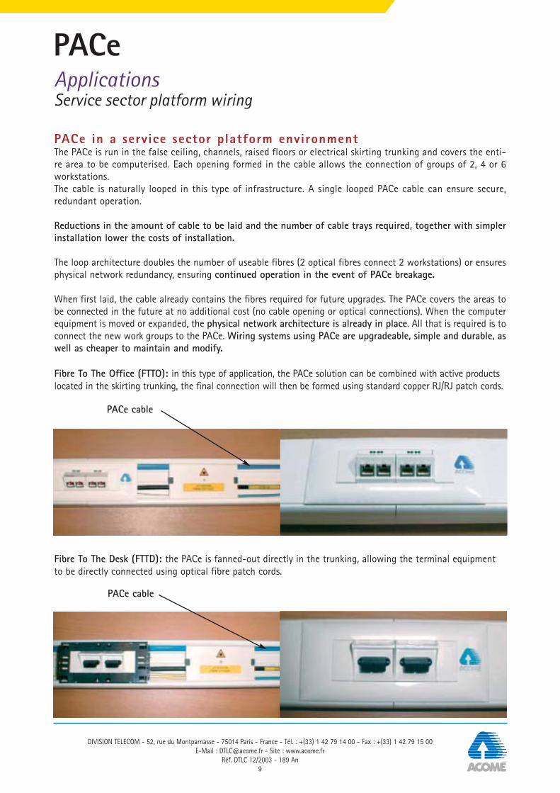
Fibre To The Office (FTTO): in this type of application, the PACe solution can be combined with active productslocated in the skirting trunking, the final connection will then be formed using standard copper RJ/RJ patch cords.
Fibre To The Desk (FTTD): the PACe is fanned-out directly in the trunking, allowing the terminal equipmentto be directly connected using optical fibre patch cords.
PACe cable
PACe cable

DIVISION TELECOM - 52, rue du Montparnasse - 75014 Paris - France - Tél. : +(33) 1 42 79 14 00 - Fax : +(33) 1 42 79 15 00E-Mail : [email protected] - Site : www.acome.fr
Réf. DTLC 12/2003 - 189 An10
PACeApplicationsWiring of high-rise office buildings
• A main cross-connect (R-G) is located on one floorof the building.
• A secondary cross-connect (R-S) is provided ateach floor level.
• Each SXC is connected to the MXC by an opticalcable that requires patching.
• Optical fibre distribution cable is required for runsexceeding the 90 m limit of copper wire.
• Horizontal cross-connects (HXC ) regularlydistributed over each floor allow the entire floorto be connected using copper or optical fibreterminal cables.
• A looped-back PACe provides 288 usable fibres for144 fibres laid.
• A separate PACe cable will be provided on eachfloor (providing an immediate or future connectioncapacity of 144 points per floor).
• In the event that the number of workstations perfloor does not justify using all the fibres of a PACe,a single PACe cable may be used to connect severalfloors.
In this type of architecture, each floor has a large surface area and a large number of points to be connected.
Traditional wiring
PACe wiring>
PACeApplicationsWiring of high-rise office buildings
DIVISION TELECOM - 52, rue du Montparnasse - 75014 Paris - France - Tél. : +(33) 1 42 79 14 00 - Fax : +(33) 1 42 79 15 00E-Mail : [email protected] - Site : www.acome.fr
Réf. DTLC 12/2003 - 189 An11
PACe in a high-rise office building environmentThe PACe runs around each floor level along the building infrastructure (corridors, channels…), remaining as close aspossible to the users. Branch connections are formed in the PACe according to the user needs.A looped cable containing 144 fibres provides 288 usable fibres for the wiring system. These 288 fibres potentially allow144 optical connections to be formed immediately or at a later date. The PACe thus forms an integral part of thebuilding's infrastructure. Installing a long term structured wiring solution increases its service life.
The secondary cross-connects are no longer required, the passive equipment, cable laying, rack installation andconnection costs are reduced to an absolute minimum, ensuring that the wiring system is cheaper to implement.
A PACe cable can serve one or several floors. The wiring will be installed to suit both the immediate andanticipated future needs: PACe cable always allows optimum management of the cables laid.

DIVISION TELECOM - 52, rue du Montparnasse - 75014 Paris - France - Tél. : +(33) 1 42 79 14 00 - Fax : +(33) 1 42 79 15 00E-Mail : [email protected] - Site : www.acome.fr
Réf. DTLC 12/2003 - 189 An12
PACeApplicationsWiring of high-rise residential buildings (broadband)
The purpose of this type of wiring is to provide a maximum number of services to mass consumers in an urbanenvironment.
A single PACe cable covers the entire building.The wiring system requires no further cables to be laid.Split-PACe will be added as and when new usersrequire to be added.
Split-PACe PACe-cordPACe
PACe wiring
A separate optical feed must be run from the maincross connect (R-G) to each potential user to avoidthe need to add cable trays or add further cables asnew customers are added.In this example, 18 two-fibre cables are required tobe laid for 3 actual users ( )
Traditional wiring
>

PACeApplicationsWiring of high-rise residential buildings (broadband)
DIVISION TELECOM - 52, rue du Montparnasse - 75014 Paris - France - Tél. : +(33) 1 42 79 14 00 - Fax : +(33) 1 42 79 15 00E-Mail : [email protected] - Site : www.acome.fr
Réf. DTLC 12/2003 - 189 An13
PACe in a high-rise residential building environment In this type of infrastructure, the service provider offering connections to a varied customer base must run theoptical cable as close as possible to each potential customer. The investment does not depend on the actualnumber of customers, but an estimate based on the connection of all potential customers. In the case of PACe,the investment is limited to the cost of incorporating the cable in the building infrastructure.
Savings are achieved in terms of the length of cable and amount of cable tray to be laid.
Investment proportional to the number of customers connected (each additional split-PACe allows theconnection of 6 new subscribers).
Category C1+ cable guaranteeing the safety of the users.

DIVISION TELECOM - 52, rue du Montparnasse - 75014 Paris - France - Tél. : +(33) 1 42 79 14 00 - Fax : +(33) 1 42 79 15 00E-Mail : [email protected] - Site : www.acome.fr
Réf. DTLC 12/2003 - 189 An14
PACeApplications
PACe and PACe Cord cables: exemplary fire propertiesThe fire properties of the materials used in the construction and fitting-out of buildings is crucial for the safety of lifeand property.
• In the event of a fire in a building open to the public, the preservation of life is of overriding importance. Thisobviously means preventing the spread of fire. It also means limiting smoke emissions, not only because oftheir toxicity (suffocation followed by asphyxia), but also because of their opacity which slows down the eva-cuation of people and the response of the emergency services.
• In the case of a fire in premises not open to the public, the priority is to save property.Certain materials release hydrochloric acid when they burn, which has the effect of corroding the metal com-ponents of the electrical and computer equipment. Damage is not limited only to the fire zone, but also occursin smoke-affected areas.It is thus essential to choose materials that release non-corrosive smoke.
Because PACe and PACe-cord cables are dedicated for internal wiring applications, they are designed to have exem-plary fire properties.
Use of low flammability, low smoke materials(non toxic and non corrosive)
The original design of the PACe and PACe-cord cables has allowed this performance to be achieved through theexclusive use of LS0H* sheathing for both the secondary coating of the optic fibres (compact tubes for PACecables, 900 µm semi-tight buffer for PACe Cords) and the cable envelope
(*LS0H: Low Smoke, Zero Halogen materials)

PACeApplications
DIVISION TELECOM - 52, rue du Montparnasse - 75014 Paris - France - Tél. : +(33) 1 42 79 14 00 - Fax : +(33) 1 42 79 15 00E-Mail : [email protected] - Site : www.acome.fr
Réf. DTLC 12/2003 - 189 An15
PACe and PACe Cord cables very successfully meet the requirementsof the Construction Products Directive (CPD)They pass the following tests:(Standardised national and international tests)
Fire resistanceIEC 60332-1 and NFC 32070 test no.1 – 1 kW burner Classification C2IEC 60332-3-24 [3C] – Test on layered wiresNFC 32070 test no. 2 – Classification C1 (80cm) and conforming with RATP K209 (30 cm)PrEN 50399-2-1 - Construction Products Directive: Euroclass C
Smoke emissionPrEN 50399-2-1 – Construction Products Directive: smoke production = s1 Acidity corrosivity = a1IEC 61034-1 and 2 – Density of smoke emissions: light transmittance >85%

DIVISION TELECOM - 52, rue du Montparnasse - 75014 Paris - France - Tél. : +(33) 1 42 79 14 00 - Fax : +(33) 1 42 79 15 00E-Mail : [email protected] - Site : www.acome.fr
Réf. DTLC 12/2003 - 189 An16
PACeSystem components
Pre-sale assistanceOur technical and sales departments are at your disposal to provide advice:• on the choice of architecture best suited to your needs,• on the fibre specification corresponding to your expectations,• regarding the selection of passive elements (connectors, splices, etc.) or active elements to be installed.
PACe wiring design document productionWe provide support for the production of• general wiring block diagrams,• cable sizes,• connection and installation drawings,• the detailed wiring file for the existing or future infrastructure.
Qualification, inspection, acceptanceIf you wish your network to be qualified for particular applications or bit rates, to perform or order an inspectionor an acceptance file, ACOME is there to assist you and ensure the success of your PACe project.• validation of wiring design,• assistance at site start-up,• validation of measuring and acceptance procedure,• site audit,• adaptation of equipment for specific systems.
ACOME training coursesACOME offers dedicated training modules relating to PACe and its implementation. These courses allow the differentplayers in the cable and wiring system market to acquire the knowledge they require in order to apply the PACe concept.These courses can complement existing optical training courses.Two modules dealing with the PACe wiring system are proposed:• Module no. 7, a new wiring concept. Intended for design engineers, computer managers, wiring system integrators. This
module provides the knowledge required for an optimum use of the PACe wiring system within the various existing net-work infrastructures.
• Module no. 8, PACe system implementation. This module is intended for installers, and covers the practical aspects ofthe installation of the different elements of the PACe system in their actual environment.

PACeSystem components
DIVISION TELECOM - 52, rue du Montparnasse - 75014 Paris - France - Tél. : +(33) 1 42 79 14 00 - Fax : +(33) 1 42 79 15 00E-Mail : [email protected] - Site : www.acome.fr
Réf. DTLC 12/2003 - 189 An17
Open-PACe – cable opening tool
This ergonomic tool is specially designed to allow the safety, accurate and speedy opening of PACe cables.• Nylon body• Stainless steel blade• Supplied in a blue case (200 x 70 x 30mm)• Weight: 300 g• Supplied with a spare blade
Clip-PACe – Closure clip
Black plastic clip serving to secure the cable in:• Split-PACe (junction boxes)• Node-PACe (break-out boxes) as well as to protect the cable at the point of opening to extract the compact tube
DIVISION TELECOM - 52, rue du Montparnasse - 75014 Paris - France - Tél. : +(33) 1 42 79 14 00 - Fax : +(33) 1 42 79 15 00E-Mail : [email protected] - Site : www.acome.fr
Réf. DTLC 12/2003 - 189 An18
PACeSystem components
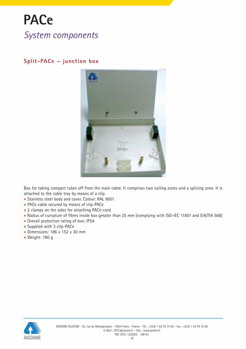
Split-PACe – junction box
Box for taking compact tubes off from the main cable. It comprises two coiling zones and a splicing zone. It isattached to the cable tray by means of a clip.• Stainless steel body and cover. Colour: RAL 9001• PACe cable secured by means of clip-PACe• 2 clamps on the sides for attaching PACe-cord• Radius of curvature of fibres inside box greater than 25 mm (complying with ISO-IEC 11801 and EIA/TIA 568)• Overall protection rating of box: IP54• Supplied with 3 clip-PACe• Dimensions: 186 x 152 x 30 mm• Weight: 780 g
PACeSystem components
DIVISION TELECOM - 52, rue du Montparnasse - 75014 Paris - France - Tél. : +(33) 1 42 79 14 00 - Fax : +(33) 1 42 79 15 00E-Mail : [email protected] - Site : www.acome.fr
Réf. DTLC 12/2003 - 189 An19
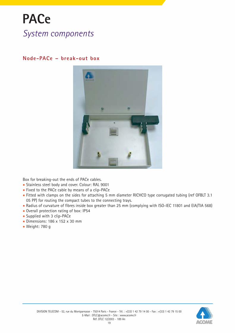
Node-PACe – break-out box
Box for breaking-out the ends of PACe cables.• Stainless steel body and cover. Colour: RAL 9001• Fixed to the PACe cable by means of a clip-PACe• Fitted with clamps on the sides for attaching 5 mm diameter RICHCO type corrugated tubing (ref OFBLT 3.1
05 PP) for routing the compact tubes to the connecting trays.• Radius of curvature of fibres inside box greater than 25 mm (complying with ISO-IEC 11801 and EIA/TIA 568)• Overall protection rating of box: IP54• Supplied with 3 clip-PACe• Dimensions: 186 x 152 x 30 mm• Weight: 780 g

DIVISION TELECOM - 52, rue du Montparnasse - 75014 Paris - France - Tél. : +(33) 1 42 79 14 00 - Fax : +(33) 1 42 79 15 00E-Mail : [email protected] - Site : www.acome.fr
Réf. DTLC 12/2003 - 189 An20
PACeSystem components
PACe• Optical fibre cable containing between 4 and 144 single mode or multi-mode fibres.• 4, 8 or 12 fibre compact tube internal module.• Modular range, containing 4, 8 or 12 compact tubes per PACe cable.• LS0H outer jacket in accordance with NFC 32062.• Exceptional fire resistance. Complies with standards like RATP standards.
PACe-cord2 mm fitted jumper optical fibre lead• 2 individually sheathed, aramid fibre reinforced
fibres with a 900 µm semi-tight buffer structure.• Glass yarn cable strengthening member.• LS0H outer jacket in accordance with NFC 32062
with flame retardant properties.

PACeSystem componentsSales references
DIVISION TELECOM - 52, rue du Montparnasse - 75014 Paris - France - Tél. : +(33) 1 42 79 14 00 - Fax : +(33) 1 42 79 15 00E-Mail : [email protected] - Site : www.acome.fr
Réf. DTLC 12/2003 - 189 An21
Equipment reference numbers
Open PACe (opening tool) IB 1306
Split-PACe (junction box + 3 clips) IB 1302
Clip-PACe (closure system) IB 1303
Node-PACe (break-out box + 3 clips) IB 1305
PACe-cord
Multimode 50/125Ref: N 6392ADelivered lengths: 100 m or 500 m
Multimode 62.5/125Ref: N 6393ADelivered lengths: 100 m or 500 m
Single modeRef: N 6394ADelivered lengths: 100 m or 500 m

DIVISION TELECOM - 52, rue du Montparnasse - 75014 Paris - France - Tél. : +(33) 1 42 79 14 00 - Fax : +(33) 1 42 79 15 00E-Mail : [email protected] - Site : www.acome.fr
Réf. DTLC 12/2003 - 189 An22
PACeSystem componentsSales references
PACe16 to 144 fibres – internal dielectric 62.5/125, 50/125, 9/125
Description 1 Compact tube : 4, 8 or 12 FOTAG colour-coded single-
or multimode optical fibres assembledwithin a thermoplastic skin
2 Strength members : Non metallic, FRP3 Outer jacket : Blue LSOH jacket complying with EN
50290-2-27: 16.6 mm wide – 9 mm high
16 fibres 4 N 6262A N 6271A N 6280A32 fibres 4 fibres per CT 8 N 6263A N 6272A N 6281A48 fibres 12 N 6264A N 6273A N 6282A32 fibres 4 N 6265A N 6274A N 6283A64 fibres 8 fibres per CT 8 N 6266A N 6275A N 6284A96 fibres 12 N 6267A N 6276A N 6285A48 fibres 4 N 6268A N 6277A N 6286A96 fibres 12 fibres per CT 8 N 6269A N 6278A N 6287A144 fibres 12 N 6270A N 6279A N 6288A
ACOME references
General cable characteristicsPACe
Temperature range:transport and storage -40°C to +70°Cinstallation -5°C to +50°Coperation -30°C to +70°C
Allowable tension (N) 1,000Crushing resistance (N/cm) 200Min. bending radius (mm) 90Fire resistance Complies with IEC 60332-1 and IEC 60322-3-24 (3C)
Complies with NFC 32070-2.1 (C2) and NFC32070-2.2 (C1)Smoke density Satisfies the requirements of IEC standards 61034-1 and 2 with a
minimum light transmittance of 85% (min. required >60%) Packaging 500 m and 1,000 m drumsNominal weight of cable (kg/km) 140Jacket marking A PACe - year and week of production – ACOME – no. and type of
optical fibres B + metric
1
2
3
Compact tube Number of PACe with PACe with PACe with 9/125 PACe capacity modularity compact tubes 62.5/125 50/125 singlemode
multimode fibres multimode fibres fibres*
* 9/125: G652 fibres
PACeSystem componentsSales references
DIVISION TELECOM - 52, rue du Montparnasse - 75014 Paris - France - Tél. : +(33) 1 42 79 14 00 - Fax : +(33) 1 42 79 15 00E-Mail : [email protected] - Site : www.acome.fr
Réf. DTLC 12/2003 - 189 An23
*9/125: G652 fibres
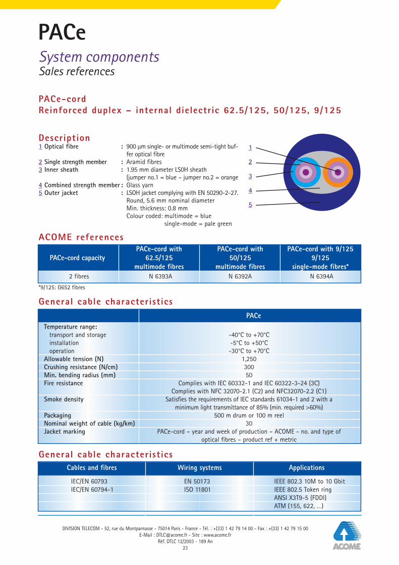
PACe-cordReinforced duplex – internal dielectric 62.5/125, 50/125, 9/125
Description 1 Optical fibre : 900 µm single- or multimode semi-tight buf-
fer optical fibre2 Single strength member : Aramid fibres3 Inner sheath : 1.95 mm diameter LS0H sheath
(jumper no.1 = blue – jumper no.2 = orange4 Combined strength member : Glass yarn5 Outer jacket : LSOH jacket complying with EN 50290-2-27.
Round, 5.6 mm nominal diameterMin. thickness: 0.8 mmColour coded: multimode = blue
single-mode = pale green
2 fibres N 6393A N 6392A N 6394A
ACOME references
General cable characteristicsPACe
Temperature range:transport and storage -40°C to +70°Cinstallation -5°C to +50°Coperation -30°C to +70°C
Allowable tension (N) 1,250Crushing resistance (N/cm) 300Min. bending radius (mm) 50Fire resistance Complies with IEC 60332-1 and IEC 60322-3-24 (3C)
Complies with NFC 32070-2.1 (C2) and NFC32070-2.2 (C1)Smoke density Satisfies the requirements of IEC standards 61034-1 and 2 with a
minimum light transmittance of 85% (min. required >60%) Packaging 500 m drum or 100 m reelNominal weight of cable (kg/km) 30Jacket marking PACe-cord – year and week of production – ACOME - no. and type of
optical fibres – product ref + metric
1
2
5
3
4
PACe-cord with PACe-cord with PACe-cord with 9/125 PACe-cord capacity 62.5/125 50/125 9/125
multimode fibres multimode fibres single-mode fibres*
IEC/EN 60793 EN 50173 IEEE 802.3 10M to 10 GbitIEC/EN 60794-1 ISO 11801 IEEE 802.5 Token ring
ANSI X3T9-5 (FDDI)ATM (155, 622, …)
General cable characteristicsCables and fibres Wiring systems Applications

DIVISION TELECOM - 52, rue du Montparnasse - 75014 Paris - France - Tél. : +(33) 1 42 79 14 00 - Fax : +(33) 1 42 79 15 00E-Mail : [email protected] - Site : www.acome.fr
Réf. DTLC 12/2003 - 189 An24
PACeSystem implementation
This chapter gives a step-by-step description of operations necessary for implementing a wiring system usingPACe cable and its associated components.
Recommended tools• Open PACe (ACOME opening tool) (1) • Scissors (2)
Connection accessories• Split-PACe: junction and connection box• Clip-PACe: system for protecting openings formed in
the cable• Node-PACe: rack or cabinet-mounted break-out box
Top of the cable
optical fibre
strength members
compact tube
1
2

PACeSystem implementation
DIVISION TELECOM - 52, rue du Montparnasse - 75014 Paris - France - Tél. : +(33) 1 42 79 14 00 - Fax : +(33) 1 42 79 15 00E-Mail : [email protected] - Site : www.acome.fr
Réf. DTLC 12/2003 - 189 An25
Forming a branch connection
Attaching the cable to the cable trayFor ease of laying and access, it is recommended to run the cable along the side of the cable tray (see photo-graphs below).
Accessing the fibresTo access the fibres, two openings (max 5 cm long) must first be formed in the cable a distance of 0.8 to 1 metreapart (length of fibre needed to form the connection).
Note: separate the cable from its support over a length of approximately 2 metres to facilitate preparation andthe forming of the branch connection.
Cable
0.8 to 1m long
First opening, 50 mm max.
split-PACeExtracted compact tube
clip-PACe
Second opening, 50 mm max.

DIVISION TELECOM - 52, rue du Montparnasse - 75014 Paris - France - Tél. : +(33) 1 42 79 14 00 - Fax : +(33) 1 42 79 15 00E-Mail : [email protected] - Site : www.acome.fr
Réf. DTLC 12/2003 - 189 An26
PACeSystem implementation
Installing and attaching the boxOnce the openings no. 1 and no. 2 are formed• Make 2 marks 105 mm apart, centred on one of the openings• Place the cable in the clip-PACe• Remove the protective paper from the foam• Close the clip-PACe
Markings 105 mm apart
Opening the cablePlace the opening tool on the cable with its blade in contact with the top of the jacket. Slide the tool forward,applying light pressure to make the blade penetrate into the jacket material. Create an opening of the desiredlength. To complete the opening and remove the cut section of jacket, lever it out by placing your thumb onthe front of the tool and lifting the back.

PACeSystem implementation
DIVISION TELECOM - 52, rue du Montparnasse - 75014 Paris - France - Tél. : +(33) 1 42 79 14 00 - Fax : +(33) 1 42 79 15 00E-Mail : [email protected] - Site : www.acome.fr
Réf. DTLC 12/2003 - 189 An27
1/ Slide the box under the cable and position theclip-PACe
2/ Place the second clip-PACe
3/ Close the second clip-PACe 4/ Re-attach the cable to the cable tray
slots to receive clip

DIVISION TELECOM - 52, rue du Montparnasse - 75014 Paris - France - Tél. : +(33) 1 42 79 14 00 - Fax : +(33) 1 42 79 15 00E-Mail : [email protected] - Site : www.acome.fr
Réf. DTLC 12/2003 - 189 An28
PACeSystem implementation
Accessing the compact tubesFollow the instructions below to extract the compact tube from the cable without damaging the fibres:• Take one of the cable jacket cuttings removed when forming the openings• Use this cutting to extract the compact tube to be connected though the opening no.2• Cut the compact tube outside the opening• Use the jacket cutting again to pull the compact out via the opening no. 1,• Remove the compact tube's thermoplastic covering to access the fibres
Closing the cableExtracting the compact tube from the cable required 2 openings to be formed. The first of these is locatedwithin the box, the other is on the cable, and must therefore be closed using a clip-PACe.• Place a clip-PACe centrally on the opening no. 2• Remove the protective paper from the foam• Close the clip-PACe
Cutting the compact tube outside the cable
Cable opening Clip after closurePlacing of the clip

PACeSystem implementation
DIVISION TELECOM - 52, rue du Montparnasse - 75014 Paris - France - Tél. : +(33) 1 42 79 14 00 - Fax : +(33) 1 42 79 15 00E-Mail : [email protected] - Site : www.acome.fr
Réf. DTLC 12/2003 - 189 An29
Installing the PACe-cordPrepare the cable as follows:• Prepare a length of cable approximately 0.8 to 1 metre long so as to have a sufficient length of 900 µm fibre
to form the connection to the compact tube,• Form a notch in the foam of the box (photograph 1),• Place the cable in the clamps provided in the box for this purpose. The 2 mm jumpers of the PACe-cord are
superimposed (photograph 2),• Before connecting, attach the PACe-cord with the PACe cable on the support (photograph 3).General view of coiled elements (photograph 4).
Note 1: SAFETY PRECAUTIONS to betaken: goggles and gloves MUST beworn. It is recommended to wear anapron when using cutting tools.
Note 2: When the cable is installedfor the first time, it is recommendedto perform a test on a sample orone end of the cable.
1
2
3
4

DIVISION TELECOM - 52, rue du Montparnasse - 75014 Paris - France - Tél. : +(33) 1 42 79 14 00 - Fax : +(33) 1 42 79 15 00E-Mail : [email protected] - Site : www.acome.fr
Réf. DTLC 12/2003 - 189 An30
ACOMEThe widest range of telecom cables
• ACOLAN® copper and optical fibre data cables for data localarea networks and premises wiring
• Cables for industrial networks and automatic control systems
• ACOTEL® copper cables for telecom networks, drop wires,connections and distribution
• Cables for switching and transmission equipment
• Copper cables for ADSL subscriber connections
• Cables for Last Mile networks
• HYPERCELL® 50 Ohm coaxial cables, connectors andaccessories for radio communication networks,radio local loop, radio-relay and broadcastnetworks
• GIGACOME® 75 Ohm coaxial cables,connectors and accessories for videocommunication networks, multimediaand voice over IP.

PACeNotes
DIVISION TELECOM - 52, rue du Montparnasse - 75014 Paris - France - Tél. : +(33) 1 42 79 14 00 - Fax : +(33) 1 42 79 15 00E-Mail : [email protected] - Site : www.acome.fr
Réf. DTLC 12/2003 - 189 An31
. . . . . . . . . . . . . . . . . . . . . . . . . . . . . . . . . . . . . . . . . . . . . . . . . . . . . . . . . . . . . . . . . . . . . . . . . . . . . . . . . . . . . . . . . . . . . . . . . . . . .
. . . . . . . . . . . . . . . . . . . . . . . . . . . . . . . . . . . . . . . . . . . . . . . . . . . . . . . . . . . . . . . . . . . . . . . . . . . . . . . . . . . . . . . . . . . . . . . . . . . . .
. . . . . . . . . . . . . . . . . . . . . . . . . . . . . . . . . . . . . . . . . . . . . . . . . . . . . . . . . . . . . . . . . . . . . . . . . . . . . . . . . . . . . . . . . . . . . . . . . . . . .
. . . . . . . . . . . . . . . . . . . . . . . . . . . . . . . . . . . . . . . . . . . . . . . . . . . . . . . . . . . . . . . . . . . . . . . . . . . . . . . . . . . . . . . . . . . . . . . . . . . . .
. . . . . . . . . . . . . . . . . . . . . . . . . . . . . . . . . . . . . . . . . . . . . . . . . . . . . . . . . . . . . . . . . . . . . . . . . . . . . . . . . . . . . . . . . . . . . . . . . . . . .
. . . . . . . . . . . . . . . . . . . . . . . . . . . . . . . . . . . . . . . . . . . . . . . . . . . . . . . . . . . . . . . . . . . . . . . . . . . . . . . . . . . . . . . . . . . . . . . . . . . . .
. . . . . . . . . . . . . . . . . . . . . . . . . . . . . . . . . . . . . . . . . . . . . . . . . . . . . . . . . . . . . . . . . . . . . . . . . . . . . . . . . . . . . . . . . . . . . . . . . . . . .
. . . . . . . . . . . . . . . . . . . . . . . . . . . . . . . . . . . . . . . . . . . . . . . . . . . . . . . . . . . . . . . . . . . . . . . . . . . . . . . . . . . . . . . . . . . . . . . . . . . . .
. . . . . . . . . . . . . . . . . . . . . . . . . . . . . . . . . . . . . . . . . . . . . . . . . . . . . . . . . . . . . . . . . . . . . . . . . . . . . . . . . . . . . . . . . . . . . . . . . . . . .
. . . . . . . . . . . . . . . . . . . . . . . . . . . . . . . . . . . . . . . . . . . . . . . . . . . . . . . . . . . . . . . . . . . . . . . . . . . . . . . . . . . . . . . . . . . . . . . . . . . . .
. . . . . . . . . . . . . . . . . . . . . . . . . . . . . . . . . . . . . . . . . . . . . . . . . . . . . . . . . . . . . . . . . . . . . . . . . . . . . . . . . . . . . . . . . . . . . . . . . . . . .
. . . . . . . . . . . . . . . . . . . . . . . . . . . . . . . . . . . . . . . . . . . . . . . . . . . . . . . . . . . . . . . . . . . . . . . . . . . . . . . . . . . . . . . . . . . . . . . . . . . . .
. . . . . . . . . . . . . . . . . . . . . . . . . . . . . . . . . . . . . . . . . . . . . . . . . . . . . . . . . . . . . . . . . . . . . . . . . . . . . . . . . . . . . . . . . . . . . . . . . . . . .
. . . . . . . . . . . . . . . . . . . . . . . . . . . . . . . . . . . . . . . . . . . . . . . . . . . . . . . . . . . . . . . . . . . . . . . . . . . . . . . . . . . . . . . . . . . . . . . . . . . . .
. . . . . . . . . . . . . . . . . . . . . . . . . . . . . . . . . . . . . . . . . . . . . . . . . . . . . . . . . . . . . . . . . . . . . . . . . . . . . . . . . . . . . . . . . . . . . . . . . . . . .
. . . . . . . . . . . . . . . . . . . . . . . . . . . . . . . . . . . . . . . . . . . . . . . . . . . . . . . . . . . . . . . . . . . . . . . . . . . . . . . . . . . . . . . . . . . . . . . . . . . . .
. . . . . . . . . . . . . . . . . . . . . . . . . . . . . . . . . . . . . . . . . . . . . . . . . . . . . . . . . . . . . . . . . . . . . . . . . . . . . . . . . . . . . . . . . . . . . . . . . . . . .
. . . . . . . . . . . . . . . . . . . . . . . . . . . . . . . . . . . . . . . . . . . . . . . . . . . . . . . . . . . . . . . . . . . . . . . . . . . . . . . . . . . . . . . . . . . . . . . . . . . . .
. . . . . . . . . . . . . . . . . . . . . . . . . . . . . . . . . . . . . . . . . . . . . . . . . . . . . . . . . . . . . . . . . . . . . . . . . . . . . . . . . . . . . . . . . . . . . . . . . . . . .
. . . . . . . . . . . . . . . . . . . . . . . . . . . . . . . . . . . . . . . . . . . . . . . . . . . . . . . . . . . . . . . . . . . . . . . . . . . . . . . . . . . . . . . . . . . . . . . . . . . . .

DIVISION TELECOM - 52, rue du Montparnasse - 75014 Paris - France - Tél. : +(33) 1 42 79 14 00 - Fax : +(33) 1 42 79 15 00E-Mail : [email protected] - Site : www.acome.fr
Réf. DTLC 12/2003 - 189 An32
PACeNotes
. . . . . . . . . . . . . . . . . . . . . . . . . . . . . . . . . . . . . . . . . . . . . . . . . . . . . . . . . . . . . . . . . . . . . . . . . . . . . . . . . . . . . . . . . . . . . . . . . . . . .
. . . . . . . . . . . . . . . . . . . . . . . . . . . . . . . . . . . . . . . . . . . . . . . . . . . . . . . . . . . . . . . . . . . . . . . . . . . . . . . . . . . . . . . . . . . . . . . . . . . . .
. . . . . . . . . . . . . . . . . . . . . . . . . . . . . . . . . . . . . . . . . . . . . . . . . . . . . . . . . . . . . . . . . . . . . . . . . . . . . . . . . . . . . . . . . . . . . . . . . . . . .
. . . . . . . . . . . . . . . . . . . . . . . . . . . . . . . . . . . . . . . . . . . . . . . . . . . . . . . . . . . . . . . . . . . . . . . . . . . . . . . . . . . . . . . . . . . . . . . . . . . . .
. . . . . . . . . . . . . . . . . . . . . . . . . . . . . . . . . . . . . . . . . . . . . . . . . . . . . . . . . . . . . . . . . . . . . . . . . . . . . . . . . . . . . . . . . . . . . . . . . . . . .
. . . . . . . . . . . . . . . . . . . . . . . . . . . . . . . . . . . . . . . . . . . . . . . . . . . . . . . . . . . . . . . . . . . . . . . . . . . . . . . . . . . . . . . . . . . . . . . . . . . . .
. . . . . . . . . . . . . . . . . . . . . . . . . . . . . . . . . . . . . . . . . . . . . . . . . . . . . . . . . . . . . . . . . . . . . . . . . . . . . . . . . . . . . . . . . . . . . . . . . . . . .
. . . . . . . . . . . . . . . . . . . . . . . . . . . . . . . . . . . . . . . . . . . . . . . . . . . . . . . . . . . . . . . . . . . . . . . . . . . . . . . . . . . . . . . . . . . . . . . . . . . . .
. . . . . . . . . . . . . . . . . . . . . . . . . . . . . . . . . . . . . . . . . . . . . . . . . . . . . . . . . . . . . . . . . . . . . . . . . . . . . . . . . . . . . . . . . . . . . . . . . . . . .
. . . . . . . . . . . . . . . . . . . . . . . . . . . . . . . . . . . . . . . . . . . . . . . . . . . . . . . . . . . . . . . . . . . . . . . . . . . . . . . . . . . . . . . . . . . . . . . . . . . . .
. . . . . . . . . . . . . . . . . . . . . . . . . . . . . . . . . . . . . . . . . . . . . . . . . . . . . . . . . . . . . . . . . . . . . . . . . . . . . . . . . . . . . . . . . . . . . . . . . . . . .
. . . . . . . . . . . . . . . . . . . . . . . . . . . . . . . . . . . . . . . . . . . . . . . . . . . . . . . . . . . . . . . . . . . . . . . . . . . . . . . . . . . . . . . . . . . . . . . . . . . . .
. . . . . . . . . . . . . . . . . . . . . . . . . . . . . . . . . . . . . . . . . . . . . . . . . . . . . . . . . . . . . . . . . . . . . . . . . . . . . . . . . . . . . . . . . . . . . . . . . . . . .
. . . . . . . . . . . . . . . . . . . . . . . . . . . . . . . . . . . . . . . . . . . . . . . . . . . . . . . . . . . . . . . . . . . . . . . . . . . . . . . . . . . . . . . . . . . . . . . . . . . . .
. . . . . . . . . . . . . . . . . . . . . . . . . . . . . . . . . . . . . . . . . . . . . . . . . . . . . . . . . . . . . . . . . . . . . . . . . . . . . . . . . . . . . . . . . . . . . . . . . . . . .
. . . . . . . . . . . . . . . . . . . . . . . . . . . . . . . . . . . . . . . . . . . . . . . . . . . . . . . . . . . . . . . . . . . . . . . . . . . . . . . . . . . . . . . . . . . . . . . . . . . . .
. . . . . . . . . . . . . . . . . . . . . . . . . . . . . . . . . . . . . . . . . . . . . . . . . . . . . . . . . . . . . . . . . . . . . . . . . . . . . . . . . . . . . . . . . . . . . . . . . . . . .
. . . . . . . . . . . . . . . . . . . . . . . . . . . . . . . . . . . . . . . . . . . . . . . . . . . . . . . . . . . . . . . . . . . . . . . . . . . . . . . . . . . . . . . . . . . . . . . . . . . . .
. . . . . . . . . . . . . . . . . . . . . . . . . . . . . . . . . . . . . . . . . . . . . . . . . . . . . . . . . . . . . . . . . . . . . . . . . . . . . . . . . . . . . . . . . . . . . . . . . . . . .
. . . . . . . . . . . . . . . . . . . . . . . . . . . . . . . . . . . . . . . . . . . . . . . . . . . . . . . . . . . . . . . . . . . . . . . . . . . . . . . . . . . . . . . . . . . . . . . . . . . . .

DIVISION TELECOM - 52, rue du Montparnasse - 75014 Paris - France - T. +(33) 1 42 79 14 00 - F. +(33) 1 42 79 15 00E-Mail : [email protected] - Site : www.acome.fr
© AC
OME
– Re
f. DT
LC 1
2/20
03 –
189
An
– De
sign
-Rea
lisat
ion:
© P.
I.C. +
33 (0
)1 4
0 27
85
90 –
With
the
purp
ose
cons
tant
ly im
prov
ing
the
perf
orm
ance
of i
ts p
rodu
cts,
ACOM
E re
serv
es th
e rig
ht to
mod
ify a
ny c
hara
cter
istic
s men
tione
d w
ithou
t prio
r not
ice.
Acom
e SC
OP w
ith a
var
iabl
e ca
pita
l R.C
.S P
aris
B 5
62 1
23 5
31 –
Sire
t: 56
2 12
3 51
3 00
011
– 14
, rue
de
Mar
igna
n 75
008
Paris
, Fra
nce.
ACOME's sales team is always at your serviceTelecom Division • Tel.: +33 (0)1 42 79 14 00 •E-mail: [email protected]
• Germany ACOME GmbH : [email protected] • Tel : 00 49 21 02 420 694
• Italy : [email protected] • Tel : 00 39 039 9280263
• UK New Bury • Tel : 00 44 163 54 71 00
• UK Manchester • Tel : 00 44 12 54 76 11 68
• Spain • Tel : 00 34 91 689 31 83
Find PACe on our web site www.acome.com