Embed Size (px)
Citation preview

Optimise Prime Page 1 of 95
┘

Solution Build Report – Lessons Learned
Optimise Prime Page 2 of 95
Table of acronyms & glossary ................................................................................ 3
Executive summary .................................................................................................. 5
1 Background & purpose ..................................................................................... 8
1.1 Introduction to Optimise Prime ............................................................................ 8
1.2 Purpose and structure of this report ................................................................. 10
1.3 Infrastructure and technology solution context ............................................... 11
1.4 Approach to solution build ................................................................................ 12
1.5 Solution overview ............................................................................................... 12
2 Trials infrastructure design & build ............................................................... 16
2.1 Approach to trials infrastructure ....................................................................... 16
2.2 WS1 – Home trial................................................................................................. 16
2.3 WS2 – Depot trial ................................................................................................ 17
2.4 WS3 – Mixed trial ................................................................................................ 24
2.5 WS4 – Supporting IT solutions .......................................................................... 25
2.6 Data Science & Analytics ................................................................................... 31
3 Commercial and technical solutions design & build .................................... 33
3.1 WS1 – Home trial................................................................................................. 33
3.2 WS2 – Depot trials .............................................................................................. 41
3.3 WS3 – Mixed trials .............................................................................................. 54
4 Trials methodology .......................................................................................... 58
4.1 Updates from Deliverable D1 ............................................................................. 58
4.2 Definition and scheduling of experiments ........................................................ 58
4.3 Sample size requirements .................................................................................. 85
4.4 Links from experiments to solution functionality and FSP commitments ...... 87
5 Preparation for trial execution: planning and progress ............................... 88
5.1 Trial timelines and phasing ................................................................................ 88
5.2 Electric Vehicles ................................................................................................. 90
5.3 Trial locations update ......................................................................................... 92
6 Incorporating learnings from other innovation projects .............................. 94
7 Conclusions & next steps ............................................................................... 95
7.1 Conclusions ........................................................................................................ 95
7.2 Next steps: Open items & future activities ........................................................ 95

Solution Build Report – Lessons Learned
Optimise Prime Page 3 of 95
Table of acronyms & glossary The acronyms and terms used throughout this document are clarified below. Table 1 – Table of acronyms
Acronym Full form ADSL Asymmetric Digital Subscriber Line ANM Active Network Management API Application Programming Interface BAU Business as Usual CBS Centrica Business Solutions CI/CD Continuous Integration/Continuous Delivery CP Charge Point CPC Charge Point Controller CSMS Charging Station Management System DAI Data, Analytics & Innovation DC/OS Distributed Cloud Operating System DER Distributed Energy Resource DMS Distribution Management System DNO Distribution Network Operator DSO Distribution System Operator EHV Extra High Voltage EPA Environmental Protection Agency EV Electric Vehicle EVSE Electric Vehicle Supply Equipment FAT Factory Acceptance Test FSP Full Submission Pro-forma GB Great Britain GDPR General Data Protection Regulation (Regulation (EU) 2016/679) HCVS Hitachi Capital Vehicle Solutions HEC(-CP) Hitachi Enterprise Cloud (Container Platform) HV High Voltage ICE(V) Internal Combustion Engine (Vehicle) ISMS Information Security Management System IT Information Technology kVA Kilo-volt-ampere kW Kilowatt kWh Kilowatt hour LAN Local Area Network LCT Low Carbon Technology (e.g. solar photovoltaics, battery storage) LPN London Power Networks plc LV Low Voltage MID Measuring Instrument Directive MPAN Meter Point Administration Number NIA Network Innovation Allowance NIC Network Innovation Competition NEDC New European Driving Cycle O&M Operations and Maintenance

Solution Build Report – Lessons Learned
Optimise Prime Page 4 of 95
Acronym Full form OCPP Open Charge Point Protocol PDI Pentaho Data Integration (a Hitachi software product) PH(V) Private Hire (Vehicle) PV Photovoltaic QA Quality Assurance RTU Remote Terminal Unit SCADA Supervisory Control and Data Acquisition SFTP Secure File Transfer Protocol SoC State of Charge SPN South Eastern Power Networks plc SSV Shared Services TCO Total Cost of Ownership TOA Trials Operational Applications ToU Time of Use UID Unique Identification UK United Kingdom ULEZ Ultra-Low Emissions Zone USP Universal Service Platform V2B/G Vehicle to Building/Grid VPN Virtual Private Network VSP Virtual Storage Platform WLTP Worldwide harmonised Light vehicle Test Procedure WS Workstream
Table 2 – Glossary of terms
Term Definition Aggregator managed charging Smart charging is controlled by an aggregator to
meet their specific objectives. Depot managed charging Smart charging is controlled by/on behalf of the
depot operator in order to meet their specific objectives and adhere to connection agreement constraints.
Experiment The set of data collection, analysis and evaluation activities required to support or reject a hypothesis related to one or more sub-objectives.
Flexibility The reduction of power drawn to charge a set of commercial EVs in a specific location and for a specific duration in response to a signal or according to a schedule defined by the DNO.
Profiled connection A connection agreement where the applicable maximum demand limit (in kVA) varies according to the time of day and the season, up to 48 half-hourly time slots per day, with adherence to the profile actively managed through behind-the-meter smart systems and monitored by the DNO.
Smart charging Charging via a smart-charger equipped with two-way communication, enabling charging habits to be adaptive.

Solution Build Report – Lessons Learned
Optimise Prime Page 5 of 95
Term Definition Timed connection A connection agreement offered by UK Power
Networks where customers are offered up to four time slots in each 24-hour period where they are allowed to consume/generate with additional capacity
Un-managed charging Charging of an EV at the rate set by the connection until it reaches full charge or is disconnected.
Executive summary Optimise Prime is a third party industry-led electric vehicle (EV) innovation and demonstration project that brings together partners from leading technology, energy, transport and financing organisations, including Hitachi Vantara, UK Power Networks, Centrica, Royal Mail, Uber, Scottish & Southern Electricity Networks, Hitachi Europe and Hitachi Capital. The project will gather data from up to 3,000 EVs driven for commercial purposes through three trials. Optimise Prime will also implement a range of technical and commercial solutions with the aim of accelerating the transition to electric for commercial fleet operators while helping GB’s distribution networks plan and prepare for the mass adoption of EVs. Through cross-industry collaboration and co-creation, the project aims to reduce the impact of EVs on distribution networks and ensure security of electricity supply while saving money for electricity customers, helping the UK meet its clean air and climate change objectives. The trial period for WS3 is currently underway, with other trials scheduled to begin in July 2021. Optimise Prime’s outcomes will include:
• Insight into the impact of the increasing number of commercial EV being charged at domestic properties, and commercial solutions for managing home based charging
• A site planning tool and optimisation methodologies enabling an easier and more cost-effective transition to EVs for depot-based fleets
• A methodology for implementing profiled connections for EVs, implemented in coordination with network planning and active management tools
• Learnings regarding how useful flexibility services from commercial EVs can be to DNOs, and how such services could be implemented
• A significant dataset and accompanying analysis on the charging behaviour of commercial vehicles
This report forms the second Optimise Prime deliverable, D2, providing a comprehensive overview of the lessons learned from the solution build phase of the project. Some of the key lessons and challenges, which are discussed in more detail throughout this report, include:
• The project’s original design-build-install approach to systems and infrastructure had to be adapted to fit the pace of introduction of EVs by the partners (1.4)
• Clearly establishing the roles of all interested parties, such as CP contractors, CPMS providers and facility managers is key to the smooth introduction of smart charging (2.3.3.1)

Solution Build Report – Lessons Learned
Optimise Prime Page 6 of 95
• Large fleets may have a complex estate of multiple telematics providers, and the datasets are very large, requiring use of dedicated data analysis tools (2.3.3.2 and 3.2.2.5)
• Data security requirements of different partners vary significantly. Sufficient time is needed to understand the impact of this and implement the required policies and technical solutions (2.5.2)
• When overlaying systems onto existing infrastructure, changes made by third parties not directly involved in the project can impact project systems and processes (2.3.3.2)
• The detailed design of flexibility services impacts on system design and should be defined as early as possible in the project (3.1.1)
• Smart charging offers significant optimisation potential to depots (3.2.1.5) • In some cases, the operational implications of profiled connections could present a
barrier to adoption (3.2.1.5) • Actual vehicle movements from depot fleets may vary significantly from expected shift
patterns (3.2.2.5) • Minimising only EV load at a depot is of limited value. The full load of the site must be
taken into account (3.2.2.5) • While comprehensive charge point (CP) location databases exist, care must be
exercised regarding their accuracy (3.3.1.3) Section 2 focuses on the infrastructure being put in place to support the trials while Section 3 introduces the scope of the commercial and technical solutions being developed in Optimise Prime. For each of these, it describes the process followed to develop the solutions, and highlights the challenges that were faced and how these were overcome. In addition, Section 4 revisits the trials methodology, introduced in deliverable D1, detailing further developments in the trial design. Section 5 provides a brief update on the progress made in preparing for the trials. Section 6 highlights some of the existing innovation projects that have been considered in carrying out this phase of Optimise Prime. Section 7 presents key conclusions from the solution build phase. While the development of the core IT platform is now complete, the Optimise Prime solutions are being continuously developed using an agile methodology, and as such the project will continue to improve and develop the solutions throughout the duration of the project. Any further changes and lessons learned will be captured through future deliverables and the project close down report. This report should prove valuable to any DNO considering how to plan for the future growth of commercial EVs, as well as to vehicle fleet operators planning to implement EV infrastructure and supporting IT systems. Although some aspects of the trial design are specific to Optimise Prime and its partners, the principles and objectives are applicable to all DNOs and to vehicle fleets planning a transition to ultra-low emission vehicles, and the project is dedicated to creating solutions that will be applicable to all GB DNOs. Table 3 shows the requirements of Deliverable D2, set out in the Project Direction, and where each item can be found within this report.

Solution Build Report – Lessons Learned
Optimise Prime Page 7 of 95
Table 3 – Deliverable D2 Requirements Deliverable D2 : Solution build report – lessons learned Evidence item Relevant section of the report Report setting out the: Lessons learned from the infrastructure build
Lessons learned from the specification and build of project infrastructure can be found in Section 2. Note that the installation and testing phases will be considered in more detail in Deliverable D3.
Lessons learned from the technology build
Lessons learned from the technology build can be found in Section 3.
Description of the methodology to be used for the trials
The trial methodology was introduced in Deliverable D1, further detail is provided in section 4.
Optimise Prime is committed to sharing the project’s outcomes as widely as possible. The project will continue to engage with a wide group of stakeholders throughout the fleet, Private Hire Vehicle (PHV), technology and energy industries through a programme of events, reports, and the project website www.optimise-prime.com.

Solution Build Report – Lessons Learned
Optimise Prime Page 8 of 95
1 Background & purpose This report, the second deliverable of the Network Innovation Competition (NIC) funded Optimise Prime project, describes the approach and lessons learnt from implementing the technical systems and infrastructure required to carry out the three Optimise Prime trials. It builds on the work presented in Deliverable D1, which outlined the high level design of the three trials and the supporting solution.
1.1 Introduction to Optimise Prime Optimise Prime is an industry-led EV innovation and demonstration project that brings together partners from leading technology, energy, transport and financing organisations, including Hitachi Vantara, UK Power Networks, Centrica, Royal Mail, Uber, Scottish & Southern Electricity Networks, Hitachi Europe and Hitachi Capital. The role of each partner is described in Table 4. Table 4 – Project Partners Partner Description Project Role Hitachi is a leading global technology
group committed to bringing about social innovation. Three Hitachi companies are project partners. Hitachi Vantara, Hitachi Europe, and Hitachi Capital.
Hitachi leads the project, providing overall project management, energy and fleet expertise and project IT platforms. Hitachi is also developing tools for the depot trial.
Electricity Distribution Network Operator (DNO) covering three licenced distribution networks in South East England, the East of England and London. The three networks cover an area of 30,000 square kilometres and over eight million customers.
London Power Networks (LPN) is the project’s funding licensee. UK Power Networks provides networks expertise and is developing new connections methodologies and flexibility products.
The electricity DNO covering the north of the Central Belt of Scotland and Central Southern England.
Supporting experiments within the Central Southern England region, ensuring wider applicability of methods.
Royal Mail provides postal delivery and courier services throughout the UK. It manages the largest vehicle fleet in the UK with over 48,000 vehicles based at 1,700 delivery offices.
Royal Mail is electrifying depots and operates EVs. Project tools will be tested in the depots and data from the vehicles will be captured.
Uber is the fastest growing PHV operator in the UK. Over 70,000 partner-drivers use the app in the UK, with the majority in and around London.
Uber is providing journey details from EV PHVs operating in London for the mixed trial.
Centrica is a UK based international energy and services company that supplies electricity, gas and related services to businesses and consumers.
The British Gas commercial vehicle fleet will participate in the trial. Centrica will also provide charging and aggregation solutions for the home trial.

Solution Build Report – Lessons Learned
Optimise Prime Page 9 of 95
Data from up to 3,000 EVs driven for commercial purposes will be gathered and analysed. The EVs will primarily be based in London and the South East of England. Optimise Prime will also implement a range of technical and commercial solutions with the aim of accelerating the transition to electric for commercial fleet operators while helping GB’s distribution networks plan and prepare for the mass adoption of EVs. Through cross-industry collaboration and co-creation, the project aims to ensure security of energy supply while saving money for electricity customers, helping the UK meet its clean air and climate change objectives. Optimise Prime aims to be the first of its kind, paving the way to the development of cost-effective strategies to minimise the impact of commercial EVs on the distribution network. Commercial EVs are defined as vehicles used for business purposes, including the transport of passengers and goods. Compared to vehicles used for domestic purposes, commercial EVs will have a much greater impact on the electricity network. The additional impact of commercial depot based EVs results from two factors: co-location of multiple EVs at a single depot location, and higher energy demand per vehicle resulting from higher daily mileages and payloads. The latter is also a factor when commercial EVs are charged at domestic locations. Two DNO groups (UK Power Networks, Scottish & Southern Electricity Networks) across four licence areas are involved in the project. The consortium includes two of the largest UK commercial fleets and a major PHV operator. The project aims to involve up to 3,000 vehicles. This scale will allow the industry to robustly test different approaches to reducing the impact of vehicle electrification on distribution networks, in advance of mass adoption throughout the 2020s. This will also help understand the impact of a wide range of variables, including different network constraints, typical mileage and driving style, traffic characteristics, location (urban, sub-urban, rural) and availability of public “top-up” charging on the feasibility of electrification of commercial vehicle fleets. By studying this diversity, the learnings generated by the project will be applicable to the whole of GB. Optimise Prime will deliver invaluable insights by using data-driven forecasting tools designed to allow networks to proactively plan upgrades. In addition, this project will create a detailed understanding of the amount of flexibility that commercial EVs can provide to the network through smart charging. Finally, a site planning tool will allow Royal Mail to request profiled connections (a new type of connection, providing a consumption connection capacity limit that varies throughout the day) from the DNO. Taken together, these form a set of innovative capabilities that allow for greater network utilisation. Optimise Prime will seek to answer three core questions, set in the project’s Full Submission Pro-Forma (FSP), relating to the electrification of commercial fleets and PHVs: 1. How do we quantify and minimise the network impact of commercial EVs? We will gain a comprehensive and quantified understanding of the demand that commercial EVs will place on the network, and the variation between fleet and vehicle types. We will achieve this through large-scale field trials where we will capture and analyse significant volumes of vehicle telematics and network data. This data will enable the creation and validation of practical models that can be used to better exploit existing network capacity, optimise investment and enable the electrification of fleets as quickly and cheaply as possible.

Solution Build Report – Lessons Learned
Optimise Prime Page 10 of 95
2. What is the value proposition for smart solutions for EV fleets and PHV operators?
We will gain an understanding of the opportunities that exist to reduce the load on the network through the better use of data, planning tools and smart charging. Additionally, we will consider and trial the business models that are necessary to enable these opportunities. We will achieve this by developing technical and market solutions, and then using them in field trials to gather robust evidence and assess their effectiveness. 3. What infrastructure (network, charging and IT) is needed to enable the EV
transition? We will understand how best to optimise the utilisation of infrastructure to reduce the load on the network. This will be achieved through the collection, analysis and modelling of depot-based, return-to-home fleet and PHV journey data. Answering these questions will enable network operators to quantify savings which can be achieved through reinforcement deferral and avoidance while facilitating the transition to low carbon transport. The trial will also assess the journey data to understand the charging and associated IT infrastructure requirements and implications for depot and fleet managers to be able to operate a commercial EV fleet successfully.
1.2 Purpose and structure of this report The purpose of this report is to set out the lessons learned from the infrastructure and technology build for the trials. The report also includes a description of the methodology to be used for trials. This report is intended to be used by project stakeholders to help guide their work in implementing the systems and infrastructure needed to enable the transition to EV for commercial vehicle fleets. Section 2 explains the technology infrastructure that has been selected for the project and the lessons learned from its initial implementation. Section 3 introduces the approach to technology and solution design and build, including the design of the commercial products and systems, detailing the progress made in building the applications. Section 4 builds upon the trials design presented in Deliverable D1, further detailing the methodology and plans for the trials. Section 5 provides an update on the progress made to date in preparing for the trials. Section 6 explains how Optimise Prime have worked with other funded projects in delivering Optimise Prime and incorporated the learnings from past projects to avoid duplication of effort. Section 7 provides conclusions based on the work done so far and highlights open items that will be worked on in the next stage of the project.

Solution Build Report – Lessons Learned
Optimise Prime Page 11 of 95
1.3 Infrastructure and technology solution context The main elements of the infrastructure and technology solution were set out in the FSP and are designed to support the three trials and two project methods. The trials, shown in Table 5, broadly align with the fleets of Optimise Prime’s three project partners, although the methods are being designed so that they have relevance to the wider commercial vehicle sector. Table 5 – Optimise Prime trials Trial Number
Name Partner Description
1 Home Charging 1
A field study of charging behaviour and flexibility with a return to home fleet.
2 Depot Charging
A field study of charging behaviour and flexibility with a depot-based fleet. Additionally, testing of profiled connections.
3 Mixed Charging
A study based on analysis of journey data from electric PHVs.
The use cases are described in more detail in the next section. As stated in the FSP, two methods will be tested through the trials. They are summarised in Table 6. Table 6 – Optimise Prime methods Method 1 Smart demand response for commercial EVs on domestic connections
Currently the additional peak demand would trigger significant network reinforcement with the costs being entirely socialised as domestic and non-domestic use is blended together. In Optimise Prime we aim to separate the commercial loads to make them visible, testing demand response approaches with commercial EVs charging at domestic premises to identify and quantify the available charging flexibility.
Method 2 Depot energy optimisation and planning tools for profiled connections
Currently, depots request a connection based on ‘worst case’ estimated peak demand, often triggering network reinforcement. The cost is part paid for by the connecting customer and part socialised across connected customers. In Optimise Prime, we aim to design and test smart charging and energy optimisation ‘behind the meter’, at depots, to be able to conform to an agreed profiled connection. We are developing the tools and processes to calculate the optimal connection profile and infrastructure, for each site, to minimise the connection cost and/or capacity used. We will also test demand response approaches to identify and quantify the available charging flexibility from an optimal profile. The project will develop the commercial arrangements to enable the rollout of the method following the project.
1 British Gas is a subsidiary of project partner Centrica.

Solution Build Report – Lessons Learned
Optimise Prime Page 12 of 95
1.4 Approach to solution build In the FSP, it was originally planned that Optimise Prime would be structured with defined ‘Design’, ‘Build’, ‘Install’ and ‘Run’ phases. As the project was planned in more detail, and the partners’ plans for EV purchase became more concrete, it became clear that it would be beneficial for the project to take a more agile approach to design, build and installation. Key factors driving this change include:
• The delay in the availability of EVs with the specifications required by fleet partners on the market, and the difficulty of designing some elements of the solution until the EVs and their locations have been specified
• A decision by the project board to extend the project and suspend some development work while vehicle numbers were confirmed
• EVs are introduced steadily throughout the project, and charging infrastructure needs to be put in place along the same schedule to allow the partners to charge and operate their EVs as soon as they are on the road
• Some elements of the technical solution are dependent on other designs such as the flexibility approach and the profiled connection design
• The benefits of being able to evolve the technical solution throughout the project, based on learnings from initial trials.
As a result of this, the project has completed some installation and commissioning activities ahead of the original schedule, while some technology is still to be built. Where this is the case, it is noted in this report and the lessons learned will be reported in future deliverables.
1.5 Solution overview The Optimise Prime technology solution is being developed to enable the trials to be run and the methods, described in section 1.3, to be implemented and tested. Figure 1 shows the current architecture design for the project. The solution consists of three main systems:
• The EV CPs deployed and operating within the trial partners’ depots and engineer homes, and Charge Point Controllers (CPCs) within each of the depots.
• Hitachi’s Universal Service Platform (USP) that provides hosting for the following sub-systems:
o Trials Operational Applications (TOA) – A collection of applications and services to plan the connection requirements for depots, optimally control vehicle charging at depots in line with a profiled connection, dispatch and manage flexibility services and manage the completion of the trials experiments.
o Data, Analytics and Innovation (DAI) – A collection of tools and services that ingest, extract, transform and load vehicle, network and supplementary data into persistent storage. The DAI also provides an environment and set of tools to explore, model and report on the collated data.
o Shared Services (SSV) – A set of tools to facilitate the build and operation of the TOA and DAI sub-systems.
The hardware and software solution of Hitachi’s USP is detailed in section 2.5.1. The TOA sub-system is described into more detail in section 3.2.5.
• External Data Providers that provide both historical and near real-time data into Hitachi’s USP to support the function of the TOA and DAI sub-systems.

Solution Build Report – Lessons Learned
Optimise Prime Page 13 of 95
Figure 1 – Optimise Prime technology architecture

Solution Build Report – Lessons Learned
Optimise Prime Page 14 of 95
Figure 2 presents a high-level view of how the Optimise Prime solution has been designed to facilitate the flow of external data from the project partners and third party sources into Hitachi’s USP and its core components. Some of the technologies being used to implement and manage this flow are listed in the right-hand side of the diagram. The ingestion processes have been built to enable the external data to flow through the Data Ingestion, Transformation and Validation component into both the Data Persistence (Object storage and Warehouse) components and directly into the Operational (Flexibility Management and Fleet EV Optimisation) components where applicable. The data ingestion processes built encompass both historical batch data uploads and streaming of near real-time data. Streamed data is routed to both the Data Persistence and Operational components to ensure that minimal lag is encountered between receipt and processing by the Operational components. From the data storage components, the data is made available to the analytics, innovation and reporting component in order to be analysed, modelled and reported on. Models and algorithms developed within this component will be passed into the Flexibility Management and Fleet EV Optimisation components where applicable. In addition to the Hitachi technical solution, progress has been made on defining the design of the project’s approach to flexibility, profiled connections and a total cost of ownership (TCO) model for the electrification of fleets.

Solution Build Report – Lessons Learned
Optimise Prime Page 15 of 95
Figure 2 – External Data Source Flow Architecture

Solution Build Report – Lessons Learned
Optimise Prime Page 16 of 95
2 Trials infrastructure design & build
2.1 Approach to trials infrastructure Optimise Prime is a data driven project, collecting and analysing information from a wide range of sources in order to develop insights into charging patterns and implement the methods. As a result of this, implementation of the core Hitachi USP was necessary early in the project to facilitate the development of other features, such as data integration, applications and data science. In parallel to this, the project and its partners have progressed the specification and build of physical infrastructure, such as EV CPs and the communications infrastructure needed to monitor and control loads taking part in the project. In the sections below, the infrastructure is split by trial workstream: WS1 Home trial, WS2 Depot trial or WS3 Mixed trial. Some elements of the project infrastructure are shared between multiple trials. WS4 details the development of the underlying platform that supports all of the trials.
2.2 WS1 – Home trial WS1 is the home charging trial, focused on controlling the charging of commercial EVs that are kept at drivers’ homes. The trial will collect data from the vehicles and chargers and will test the provision of flexibility services through the control of vehicle charging. In Optimise Prime, the trial will involve Centrica’s British Gas maintenance fleet of electric light commercial vehicles.
2.2.1 WS1 charging infrastructure The charging infrastructure utilised in WS1 is installed and maintained by Centrica. Evaluation of a number of CP models was carried out by Centrica in order to select an appropriate model. Key criteria were interoperability, Measuring Instrument Directive (MID) compliant metering for recording fleet usage including use of RFID, supplier track record and price. The tender was sent to around 15 providers and six were shortlisted. As a result of this, an Alfen Eve Single CP, as shown in Figure 3, is being installed at each driver’s home in advance of them receiving an EV. It will communicate with Centrica’s charging management systems using Open Charge Point Protocol (OCPP) version 1.6. Figure 3 – EV CP installed at British Gas driver's home by Centrica

Solution Build Report – Lessons Learned
Optimise Prime Page 17 of 95
2.2.2 WS1 data infrastructure The main data sources for WS1 are the EVs and CPs located at drivers’ homes. Table 7 details the approach being taken to collect data for analysis and the key considerations that are being taken into account. Table 7 – WS1 data infrastructure
Collection Approach Specific Considerations Vehicles The vehicles will be monitored through
Centrica’s current telematics solution, which is used across both the ICE and EV fleets, allowing for comparison. This enables the monitoring of vehicle usage patterns. A regular extract will be taken from the telematics solution provider and sent via secure file transfer protocol (SFTP) to the project platform.
• GDPR considerations • Ease of solution as it’s used
today • Fits within Centrica’s existing
fleet solution • Minimal consultation with
British Gas’s driver union required
Homes Currently the project is not expecting to collect home data (other than charging data) for the purposes of the trial. This would require additional dialogue with British Gas’s driver unions and this may limit the expandability of a solution relying on this type of data. Centrica are looking at alternatives internally to model home energy for different use cases.
• GDPR and data privacy is the main consideration
Chargers The CPs are smart and Centrica is currently investigating the approach that will be used to collect data. The preferred option is to create an extract from the chargers that can be sent to the project system for analysis in the same way that is being done for the vehicles.
• OCPP compliance and interoperability are vital for this to be rolled out across GB
• Minimising additional effort/expense by making use of the existing functionalities of the CPs
Some of the aspects of integration between data from the Centrica infrastructure and Hitachi systems for subsequent analysis are still to be determined, but the broad approach is for the systems to communicate in a relatively simple and robust manner as the data collection is for trial purposes. Experience from this will inform how best to provide these services at greater scale in the future.
2.2.3 Learnings from WS1 design & build No significant learnings have been identified in the design and build of the WS1 infrastructure, learnings from the development of the WS1 solution can be found in Section 3.1.
2.3 WS2 – Depot trial WS2 is the depot charging trial, focused on controlling sites where a number of vehicles will charge simultaneously. In Optimise Prime, battery-electric vans at seven Royal Mail depots in and around London will be smart-charged in order to comply with profiled connections. Flexibility provision will also be tested.

Solution Build Report – Lessons Learned
Optimise Prime Page 18 of 95
2.3.1 WS2 charging infrastructure The infrastructure to support the management of smart charging in WS2 includes CPs and a communications solution, as shown in Figure 4. The communications system has the functionality to intercept messages flowing between each CP and the Charging Station Management System (CSMS, commonly known as a “back office” system) and divert them to an optimisation system, hosted on the project’s platform. The system can then send new CP set-point commands into the traffic stream to start and stop charging based on the outcome of the optimisation. This basic methodology was identified as a requirement for the project’s method because it is currently not possible to accomplish this via the CSMS (as the project does not own or control the CSMS). Figure 4 – WS2 charging infrastructure
2.3.1.1 Charging infrastructure specification As is likely to be the case in many future smart charging projects, the smart charging infrastructure utilised in Optimise Prime is an overlay over existing charging infrastructure. In the case of Royal Mail, each depot has some pre-existing infrastructure from a previous electrification project, to which is added a substantial expansion of additional charging capacity to cope with the new EVs. The procurement of the new charging infrastructure occurred separately to Optimise Prime (as its provision was a contribution to the project by Royal Mail Group) and therefore the influence the project has over it is limited. It was primarily designed to meet the operational and procurement requirements of Royal Mail. The pre-existing and new charging infrastructure are supplied under different contracts from different suppliers. Consequently, the project is required to work with a mix of manufacturers and models of CPs, CSMS and support arrangements. This adds a degree of both technical and commercial complexity. The numbers and types of equipment deployed are shown in Table 8 and examples of these CPs are shown in Figure 5. Table 8 – CPs at Royal Mail Depots CP Type Alfen twin Alfen single Swarco eVolt twin Number of EVSE (2 x EVSE) (1 x EVSE) (2 x EVSE) CSMS GeniePoint GeniePoint e.Connect Royal Mail Site
Mount Pleasant 40 7 0 Premier Park 21 3 3 Whitechapel 12 3 3 Islington 7 4 3 Dartford 7 2 3 Bexleyheath 0 0 3 Orpington 0 0 3

Solution Build Report – Lessons Learned
Optimise Prime Page 19 of 95
Figure 5 – Legacy Swarco eVolt twin (left) and newly installed Alfen twin (right) CPs at Royal Mail Depots
Prior to the project, each CP was deployed with its own cellular connection to the CSMS. Implementing communications in this way minimised the need for network infrastructure and cabling within the depot site at the expense of increased communications cost. Communication over the public internet utilising dedicated cellular communication also simplified information security arrangements for the CP installation contractor. This approach, adopted by Royal Mail’s contractor, unfortunately presented a significant technical issue to Optimise Prime, as it did not allow for local control of the individual chargers within each depot. To implement smart charging it is a requirement to be able to communicate with each CP individually, to receive telemetry from it and to send charge current set-points (i.e. start/stop or ramp up/down commands) to it. This can be achieved in two ways, as illustrated in Figure 6:
1. Via the CSMS; and 2. By intercepting traffic flowing between the CP and the CSMS.
Figure 6 – Smart charging options

Solution Build Report – Lessons Learned
Optimise Prime Page 20 of 95
Option 1 requires integration with the CSMS and functionality development on the CSMS, which may be explored later in the project. Option 2 requires diversion of traffic from cellular communications to a separate smart charging network. As the viability of Option 1 was not known when the project was planned, the second option is used in the Optimise Prime methods. Nortech Management Limited were chosen, by competitive tender, to provide dedicated infrastructure comprising on-site CPC units, communications gateways and a management system, iHost, capable of integrating with both the CSMS and the depot optimisation system. This method was chosen as a way to guarantee that the project’s set point commands would not be over-ridden by the CSMS (as the system intercepts traffic). The project is considering also trialling Option 1 should it become necessary to add further depots to the project, subject to collaboration with the CSMS provider, allowing the comparison of the benefits of the two approaches. Throughout the design of the CP control system, a principal concern has been to minimise any impact on the CSMS provider or their system, so as not to create unnecessary alerts or interrupt the management of the CPs as a result of removing the direct cellular connection between the CPs and CSMS. To avoid this happening, a Virtual Private Network (VPN) connection was set up between iHost and the CSMS provider to pass through communications between the CPs and the CSMS. The architecture of the solution installed within the depots is shown in Figure 7. Figure 7 – Depot Smart Charging system architecture

Solution Build Report – Lessons Learned
Optimise Prime Page 21 of 95
Changing the communications and control method for the CPs for the purpose of option 2 increases the technical complexity of the charging installation at each Royal Mail site. In order to mitigate any issues arising from this, the project decided to build a Factory Acceptance Test (FAT) site where functionality and processes can be verified prior to implementation on the active Royal Mail depots, minimising the potential for disruption to their business activity. The FAT site chosen belongs to project partner Hitachi Capital Vehicle Solutions (HCVS) in Trowbridge, Wiltshire. The FAT site is equipped with one of each model of CP installed on Royal Mail sites (Alfen Eve single and twin socket, and Swarco eVolt twin socket), together with a CPC. Communication is via cellular connectivity to the Internet. Nortech installed and commissioned the installation at Trowbridge as a turnkey delivery. The installation is shown in Figure 8. Figure 8 – FAT site at HCVS Trowbridge, showing the Swarco CP to the right and Alfen CPs either side of the grey distribution cabinet
In order to monitor the utilisation of connection capacity at each site and ensure that this capacity is not exceeded near real-time load monitoring is needed, taking into account both EV and other site loads. As the existing metering at the Royal Mail sites was not able provide third party access to load data the project conducted research into alternative secondary metering options. Centrica Business Solutions’ (CBS) Panoramic Power solution was identified as a low cost fit to the project need. This solution provides a feed of site power data via a secure internet gateway into the project systems. The chosen solution has the added advantage that it is non-invasive and can be installed without interrupting the power supply to the site. Panoramic Power utilises self-powered current clamps that connect to a bridge unit via a wireless connection, removing the need for additional cabling. The bridge at each site connects to Panoramic Power’s systems via a cellular connection.
2.3.2 WS2 data infrastructure In addition to the physical infrastructure at the Royal Mail depot sites, it has been necessary to connect this infrastructure to USP to allow the capture of data for analysis and the sending of control signals. In addition, a number of other data sets will be utilised in the project’s analysis and optimisation. Figure 2 depicts how data from the various external sources supporting the WS2 trial are ingested into the USP. In the diagram, they are grouped into DNOs, Depot Based Fleets (Royal Mail) and Supporting Data and are summarised in Table 9.

Solution Build Report – Lessons Learned
Optimise Prime Page 22 of 95
Table 9 – WS2 data sources Data Source Description EV fleet telematics Collection of state of charge (SoC), distance travelled and
a range of other data from Royal Mail vehicles. Implemented for three different telematics providers using a range of technologies, reflecting Royal Mail’s existing suppliers. Includes both near real-time streaming data and historic batch data.
EV fleet charging Communication with the Nortech iHost system via REST API for the control of charging and collection of data.
Depot energy monitoring Frequent load data for each site is ingested to the USP via Panoramic Power’s SFTP service.
Flexibility and active network management (ANM)
Data is exchanged with the DNO in order to trigger flexibility services. Profiled connections from the DNO are input to the optimisation system.
Operational reference data
Manually supplied data regarding vehicles and depots.
Other Forecast and actual weather (in order to identify any weather related trends in charging patterns), historic network demand data and CP location data is regularly updated (either by API or by manual process) for use in analysis across all Optimise Prime trials.
The majority of the ‘ingestors’ that collect this data and store it ready for analysis or use in the applications have now been built. Over the coming months, small enhancements may be made, such as updates to address changes by data providers, but the primary activity will be to capture and persist operational data. Data for the depot-based fleets is routed to both the data storage and operational components where applicable. The solution is now receiving the majority of data from the depot-based fleets (including CP, telematics and depot energy) into the data storage components and this is being used for analysis. The remaining datasets to be ingested are related to profiled connections and flexibility which are provided by UK Power Networks. They are currently being agreed upon. In addition to the implementation of the UK Power Networks data sources, the use of the data within the operational components of the solution (such as depot optimisation and flexibility) will be the focus of the TOA sub-system development over the next few months.
2.3.3 Learnings from WS2 infrastructure design & build
2.3.3.1 Learnings from designing the depot infrastructure The role and responsibilities of the CP contractor, CSMS provider and other stakeholders in enabling managed smart charging A key requirement in developing a project of this type is to involve the CP contractor and the CSMS provider in the design as it develops to ensure the impact on the existing charging solution is minimised, particularly on their ability to discharge their contractual Operations and Maintenance (O&M) obligations to the fleet operator (in this case Royal Mail).

Solution Build Report – Lessons Learned
Optimise Prime Page 23 of 95
The requirement to intercept traffic at a central hub located on site, as illustrated in Figure 7, in order to facilitate smart charging leads to the migration of CP communications to a Local Area Network (LAN). This has the added benefit of increasing communications reliability and availability, since the cellular connection is retained as a fall-back. Communications redundancy is further enhanced by supporting both fixed line (ADSL) and cellular connectivity on the CPC. Agreement from the CP O&M provider is required to permit the configuration change of each CP from cellular connectivity to LAN. As the CPC units support their own internet access, there is no need for any of the smart charging infrastructure (including the CPs) to communicate with any on-site facilities. The smart charging LAN is physically segregated from Royal Mail’s LAN, thereby minimising any security implications. The physical wiring itself did, however, need to comply with Royal Mail’s requirements and also needed to be added to their asset inventory. Initially, the decision was taken to treat the smart charging LAN as a turnkey solution provided by Nortech, but this proved to lead to a complex contracting arrangement. This was changed such that Royal Mail was subcontracted by the project to provide the LAN to Nortech’s requirements while following Royal Mail’s wiring specifications. This also means that the physical LAN is maintained by Royal Mail rather than the project. Nortech provided the CPC and additional networking equipment such as fibre switches. Table 10 summarises the optimum responsibilities that were agreed upon. In a new installation, where CPs and CPCs were being installed at the same time, it would be preferable to specify the cabling as part of the CP installation in order to simplify the process. Table 10 – Responsibilities matrix Element Responsibility CP Charging contractor CPC and other active network equipment Smart charging contractor (Nortech) LAN cabling and power provision Facilities owner (Royal Mail)
As well as the on-site integration, the Nortech management system “iHost” requires a connection to the CSMS to forward CP traffic for transparent O&M (from the perspective of the CSMS). This connection is implemented between the two systems over the Internet using a standards-based VPN for simplicity and security. This required minimal work on behalf of the CSMS provider. In addition to the communications infrastructure for charging, the Optimise Prime optimisation algorithms require near real-time information on the site power demand, in addition to demand from EV charging activity, in order to tell whether the site is approaching its maximum power requirement connection capacity. A site survey proved to be essential in implementing the secondary metering solution. In some cases, the incoming power feed was found to be in a basement location with poor cellular coverage. The survey also provided the opportunity to fully specify the required metering as supplies at some sites proved to be complicated, having evolved over time. UK Power Networks will also install load monitoring on the distribution network side of the incoming supply for each site in order to monitor the adherence to profiled connections.
2.3.3.2 Learnings from designing the data infrastructure Complexity of integrating telematics systems Integrating with the telematics systems for WS2 took significantly longer than was originally planned. The project is utilising Royal Mail’s existing telematics systems, both in order to save

Solution Build Report – Lessons Learned
Optimise Prime Page 24 of 95
on the cost of project-specific infrastructure and to prevent disruption to Royal Mail business as usual (BAU) operations. It was originally anticipated that the project would need to interface with a single system, however due to the trial vehicles being supplied by different manufacturers it was necessary to implement integration with three different telematics systems. Each system was found to structure data differently and required different technologies to be used to capture the data. This requirement was not known at the outset of the project because the vehicles had not been procured, but future projects involving telematics should be aware of this potential complexity. Impact of third-party solutions on the project Reliance on existing third-party solutions has also introduced some complexity, as system changes by suppliers over which the project has no control can have unintended impacts on the project systems, requiring resolution. The project experienced this with regard to connections with the CSMS provider and one of the telematics providers and had to implement changes and mitigations. Future projects should ensure that they are fully aware of all the sub-contractors that may impact on the availability of data and should ensure sufficient resources have been budgeted to respond to unexpected changes.
2.4 WS3 – Mixed trial WS3 is the mixed charging trial, a data analysis exercise looking at the charging patterns and potential network impacts of PHVs. PHVs do not have a dedicated charging infrastructure and may charge at drivers’ homes or at on-street or hub based public charging points. In Optimise Prime, journey data from EVs operating on the Uber platform in Greater London is being collected and analysed.
2.4.1 Mixed trial data ingestion Figure 9 illustrates the data ingestion for the Mixed Trial. With the ingestion being purely for analysis, modelling and reporting, and not being used in any of the project methods, the data is only passed into the data storage components. Figure 9 – WS3 data ingestion

Solution Build Report – Lessons Learned
Optimise Prime Page 25 of 95
The main data source for WS3 is a monthly batch download of anonymised data from Uber’s platform via SFTP. This data includes details (time, vehicle identifier, location) of the start and end point of each ‘change of state’ (e.g. turning the app on or off, accepting a trip, starting or ending a journey) for all EVs operating on the Uber platform in Greater London. Uber also provides a mapping of vehicle identifiers to vehicle makes and models. Security and access controls are in place to manage the Uber data because, in addition to the data being anonymised, the project treats the data as personal information subject to the GDPR. The project’s security controls are discussed further in Section 2.5.3. In addition to the data from Uber, WS3 utilises the weather data (from Dark Sky) and network data described in Table 9 and public CP Location data from Zap-Map. The network data used initially comprises the capacity and maximum utilisation of secondary substations in the London area, spanning the four DNOs regions involved in the project. UK Power Networks is currently considering whether richer datasets are available to contribute to the WS3 analysis. The Analytics, Innovation and Reporting components of the project systems are being used by the Data Science and Analytics team to produce the Mixed Trials reports.
2.4.2 Learnings from WS3 infrastructure design & build No specific learnings were identified resulting from the infrastructure build for WS3. Learnings regarding data security, which impact WS3, are detailed in section 2.5.2 while learnings from the WS3 analytics can be found in section 3.3.1.3.
2.5 WS4 – Supporting IT solutions WS4 is responsible for developing the supporting IT solutions that support all of the project’s trials and analysis. In order to do this, Hitachi’s USP was built at an early stage and is now in use ingesting data, storing data and providing the compute and applications for the processing of data for the trials. This section describes the hardware and software solution implemented in order to provide this platform and focuses on the area of ensuring data security.
2.5.1 Universal Service Platform
2.5.1.1 USP Strategic Aims The Hitachi USP provides a common secure platform where the following sub-systems will be operated:
• Trials Operational Applications (TOA) • Shared Services (SSV) • Data, Analytics and Innovation (DAI).
The key aims of the USP are:
• To bring together data from a number of different sources so that it can be utilised by the trials applications to achieve the project goals
• To provide sufficient compute resources to enable the analysis of the data and the development and operation of the applications
• To do so on a secure and modern open source platform. At the core of the USP is Hitachi’s Enterprise Cloud (HEC). The HEC provides the infrastructure and platform upon which the TOA, SSV and DAI sub-systems have been built.

Solution Build Report – Lessons Learned
Optimise Prime Page 26 of 95
Development of the USP has followed the specification that was set out in Deliverable D1 in order to meet the requirements of the project.
2.5.1.2 USP Design & Build The Optimise Prime USP is composed of the following hardware architectures:
i. Hitachi Enterprise Cloud Container Platform (HEC-CP), which delivers hyper-scale operations through application orchestration in containers, developer and data analysist agility through simple orchestration of common services.
ii. Hitachi Content Platform (HCP), an object-based storage system designed to support large-scale private and hybrid cloud repositories of unstructured data.
iii. Hitachi Virtual Storage Platform F350 (VSP F350) an all flash storage solution that delivers storage capacity for the HEC-CP solution.
Figure 10 shows the logical architecture of the USP and the components implemented within the solution.
Figure 10 – USP Logical Architecture
In order to protect the analytical data generated with the Optimise Prime solution and the data science models, the storage hardware (HCP and VSP) span two physically different data centres with a separation greater than 25km. The primary site contains a complete instance of the above solution components and allows for secure authenticated user access and data ingestion. The secondary site only contains the HCP and the VSP F350 components housing a secure near real-time copy of all the data from the primary site and has no user access to this infrastructure and data.

Solution Build Report – Lessons Learned
Optimise Prime Page 27 of 95
In addition to the hardware, the following software features have been implemented in order to manage the operation of the USP:
• VMware vCenter Server, a data centre management server application that monitors virtualised environments. VCenter Server provides centralised management and operation, resource provisioning and performance evaluation of virtual machines residing on a distributed virtual data centre.
• Foreman, a management tool for provisioning, configuring and monitoring of physical and virtual servers.
• Mesosphere DC/OS (distributed cloud operating system), a cluster manager, container platform, and operating system for orchestrating the containerised applications.
• Kubernetes – a system allowing for the deployment, scaling and management of containerised applications.
• LogStash for collecting, parsing and transforming the DC/OS logs. • Aqua for securing containerised and serverless applications, from the CI/CD
(continuous integration and deployment) pipeline to runtime production environments. • RexRay, a container storage orchestration engine enabling persistence for cloud
native workloads. • Hitachi UCP Advisor provides detailed information about the infrastructure
components and allows unified management, central oversight, and smart life-cycle management for firmware upgrades, element visibility, and troubleshooting.
• Hitachi Storage Virtualization Operating System for the VSP F350 provides enterprise data management services keeping response times fast as data levels grow, and automatically recovers.
• Hitachi Content Platform (HCP), an object storage software solution that connects data producers, users, applications and devices into a central cloud self-healing storage platform.
A number of solutions have been implemented on the USP to support the requirements of the sub-systems. Table 11, Table 12 and Table 13 provide an overview of some of the key functionalities. Table 11 – TOA supporting components Requirement Solution Virtual private cloud with development, Quality Assurance (QA) and production environments
• Multiple independent Kubernetes clusters implemented on the Mesosphere container platform
Networking and Security • Aqua, an application security platform • Logstash, a log management tool
Table 12 – SSV supporting components Requirement Solution Logging & Audit • Logstash Authentication • Independent Active Directory specifically for
Optimise Prime

Solution Build Report – Lessons Learned
Optimise Prime Page 28 of 95
Table 13 – DAI supporting components Requirement Solution Analytical tools • Jupyter desktops provisioned dynamically with
automation for each data scientist collocated with the data.
• Postgres for persistent database workloads. • Spark for in memory processing of multiple
data sets, • Pentaho for data integration
Orchestration • The data scientists are able to browse and select data sets they are granted access to and delivery to their Jupyter desktop is orchestrated by Pentaho
Data Ingestion is provided within the USP for the various data sets required by the project. A combination of methods is utilised, including SFTP batch load (e.g. data from Uber), API integration (e.g. weather set data) with automated file mapping and streaming data via Kafka (e.g. streaming telematics and CP data). The structure of the data ingestion infrastructure is shown in Figure 11. Figure 11 – USP data ingestion infrastructure
The build of the USP is now complete. Throughout the rest of the project, there will be some ongoing activity in order to support the ongoing operation of the platform. Ongoing tasks will include:
• Supporting and running the platform, implementing continuous improvements based on lessons learned
• On- and off-boarding of project teams as necessary • Scaling the platform, its resources and toolsets in order to meet changes in project
requirements over time • Handling requests from project stakeholders, such as partners, vendors and security
advisors for support and enhancements.

Solution Build Report – Lessons Learned
Optimise Prime Page 29 of 95
2.5.2 Lessons learned from the WS4 solution build A thorough review of stakeholders’ varied data management requirements is needed to design appropriate policies and technical solutions At the start of the implementation of the Optimise Prime project, a thorough review was undertaken of all of the data sets that were to be utilised by the project in order to identify any individual requirements for data management. It was decided that, due to the varying requirements of the project partners, the high visibility of the project and the commercially confidential nature of some of the data, the project should implement self-containment of data and infrastructure and processes. Not only was each component used in the solution given a thorough technical review pertaining to security and appropriate hardening put in place, but an independent third party was appointed to review the full solution configuration and conduct a full set of penetration tests and review of the associated processes. Further details on the steps that the project has taken to ensure data security can be found in section 2.5.3. This process led to a slight delay in getting all the approvals from all stakeholders, completing remediation in consideration of any potential threats and putting in place the governance arrangements needed to ensure ongoing best practice. The major lesson learned here was that, in collaboration projects involving sharing of data between a number of parties, time needs to be allocated in the early phases of the project in order for all parties to gain full confidence in the security of the data sharing solution built. To aid in the navigation through this process, Hitachi Vantara’s Chief Information Security Officer who has extensive experience in these matters, maintained complete oversight and ultimate sign-off for the go-live of the system, onboarding of data and the use of the data by the data scientists. Once data is ingested into the platform, other than potential screen scraping of data, no mechanism was left available for the offloading of data and a complete audit trail and lineage is maintained of when data is ingested and when it is used.
2.5.3 Ensuring Data Security and Privacy The Optimise Prime project contains two distinct classes of data: data classified under GDPR as “personal” and data used to control smart charging. Personal data requires a number of additional information processing security obligations under the GDPR, including the implementation of processes to manage subject access requests. The requirement for Hitachi to be a data processor was not known at the time of writing the FSP, and the additional security requirements have required additional investment. Given the GDPR concerns and the operational importance of charging data, it was decided early in the project to adopt a formal approach to information security informed by best practice such as ISO 27001. An external consultancy was engaged to ensure that an information security framework could be implemented that would allow the Programme to discharge its legal and contractual obligations to stakeholders. Implementation of the project’s security processes follows three phases:
1. Framework design 2. Framework implementation: establish working groups and security procedures 3. Operation: day-to-day operation according to procedures, verification through audit
The framework comprises a set of documentation that forms a hierarchy, from framework principles through policies to standards for what is required in each information security area. The set of written policies and standards were produced by the external consultants in

Solution Build Report – Lessons Learned
Optimise Prime Page 30 of 95
conjunction with the project office. The framework is designed to fit with the scope and nature of the project – particularly given it is an innovation project and subject to rapid change. The framework documentation set contains the documents listed in Table 14. Table 14 – Hierarchy of security documentation Hierarchy Scope Framework Principles Governance
Risk Management Policies Information Security
Acceptable Use Data Management
Standards Access Control Asset Management Vulnerability Management Incident Management Network Security Data Encryption Secure Maintenance and Development Logging and Monitoring
These framework documents, whilst tailored for the project, do not specify the detailed procedures that are to be followed. Their purpose is to specify the constraints and requirements that must be operationally complied with. They were written including reference to information security standards employed by consortium partners as appropriate to avoid conflict and correct assignation of responsibility. For example, where standards touch on HR policies such as in Acceptable Use then employer policy takes precedence. A number of procedures were created to implement the information security framework operationally. These procedures detail how specific operations are to be accomplished to ensure compliance with the framework:
• Data Processing – acquisition and management of data from ingestion through to disposal.
• GDPR – processing of any request by a data subject to exercise any of their rights under GDPR.
• Incident Response – operational processes to follow upon detection of an information security incident.
• On-boarding – procedure for the introduction of the Programme information security framework to any party joining (or leaving) the programme.
• Reviews and Audits – periodic reviews of the information security framework to ensure it remains fit for purpose, continuous improvement being a core requirement of any Information Security Management System (ISMS).
• Secure Disposal – disposal of any programme information processing assets to ensure that no programme information is accessible on them following their removal from the Programme.
Collectively, these documents (framework, policies, standards and procedures) form the ISMS for the project. The ISMS will be continually reviewed to take account of both changes in the project and in the threat landscape from which it seeks to provide the project with protection. All information

Solution Build Report – Lessons Learned
Optimise Prime Page 31 of 95
security is principally concerned with risk management, and as risks change so must the management of them. The framework required the establishment of a Security Working Group, whose role is to manage the ISMS and identified risks. The Security Working Group meets monthly and reports to Hitachi’s Programme Manager. The implementation of a comprehensive ISMS was a significant investment. However, as with any risk management, the project has consistently sought to ensure that it is designed and implemented by balancing cost against benefit. The objective is to ensure that information security risk is managed to a level consistent with the needs of the project and its partners.
2.6 Data Science & Analytics On top of the core USP architecture, the project has established an analytics environment in order to analyse and create insights from the data being collected across all of the trial workstreams and to measure the efficacy of the methods.
2.6.1.1 Analytics environment strategic aims The analytics environment has been built to serve the following programme aims:
1. Trials Data Analysis a. Outputting relevant models and/or data tables for further use b. Outputting data tables to aid in the development of business models c. Outputting graphical visualisations, and potentially dashboards where
appropriate, to help stakeholders understand insights 2. Data Science, providing the project with the ability to utilise the following tools in trials
data analysis and the development of applications: a. Mathematical Modelling b. Machine Learning & AI c. Multiprocessing & Distributed computing d. “Big Data” Science where applicable – large scale distributed computing
3. Report Writing a. To support in generation of reports for successful completion of Optimise Prime
4. Creating a repeatable, reusable codebase, backed up and version controlled to aid in project efficiency and enable the future use of project learnings
a. Git (a code version-control system) integration b. Documentation generation c. Database Integration for persistent data storage and retrieval d. Multiple User Collaboration
2.6.1.2 Analytics environment build The analytics system is built on and around an engineering solution: a Jupyter Notebook frontend provides a Python-based environment for Data Analysis and Data Science, and a custom built Python library provides connector functions enabling the environment to interface with the backend persistent storage solutions (Hitachi Content Platform and PostgreSQL). Further, analysis is version-controlled and backed up in Gitlab, which allows analysis to be tracked over time and enables reversion to previous versions if required. These helper functions allow for the read and write of data. i.e. bidirectional data transfer between the Python environment and the storage component of the platform. The project will adopt the following methodology should it be necessary for any intermediate data analytics results (e.g. data tables, models, graphs) to be saved in a more persistent manner (as opposed to just storing it in the Python environment):
• PostgreSQL: Used to store data tables only (i.e. not models, graphs or any other assets)

Solution Build Report – Lessons Learned
Optimise Prime Page 32 of 95
• Gitlab: Used to store graphs and output images in the codebase. No data tables will be stored on Gitlab.
• Optimise Prime HCP Namespace: There is a specific storage container able to store any file type that is an intermediate output of a Data Science Analytics exercise, such as a model or data table. This can store any file including those above.
The Jupyter Notebook frontend allows the project to achieve strategic aims 1a-c and 3 mentioned in section 2.6.1.1. The use of standard Python Data Science libraries enables Optimise Prime to achieve aims 2a-c. In the WS2 trial, the projects involve the additional requirement to work in a “big data” regime in order to receive and manage streaming telematics data with millions of datapoints per vehicle per week. To account for this, the Jupyter Notebook environment was connected to an underlying Spark cluster which allows for larger datasets to be manipulated and analysed, fulfilling aim 2d. The Gitlab solution helps achieve aim 4a. Sphinx is used in Python for documentation generation to automatically build and serve documentation to the project’s collaboration system provided by Confluence. This enables alignment of all project documentation in a centralised location, thereby helping achieve aim 4b. The bidirectional data transfer functions described above, and the use of HCP and PostgreSQL helps achieve aim 4c. Figure 12 illustrates the data analytics environment established for the project. Figure 12 – Data analytics environment

Solution Build Report – Lessons Learned
Optimise Prime Page 33 of 95
3 Commercial and technical solutions design & build This section has been structured around the three trial workstreams, it describes the commercial and technical solutions, and related applications that are being developed in order to deliver the Optimise Prime trials and methods. These solutions will utilise the infrastructure described in Section 2 in order to gather data, send charging commands and conduct analytics.
3.1 WS1 – Home trial The home charging solution that is being built for WS1 consists of several elements. The charging and control method to be trialled is being developed by Centrica, consisting of charging infrastructure that connects via an OCPP server to their Integrated Solutions Platform and FlexPond solution. This provides optimisation and flexibility services in response to dispatch requests from UK Power Networks. In addition to the charging method, data from EV and chargers will be captured and analysed in order to provide learnings related to the charging patterns of the vehicles and the impact on the distribution network.
3.1.1 Home trial systems In order to control the charging of its new EVs, Centrica has developed a new solution based around a driver app which communicates with OCPP 1.6 compliant chargers. Some of the functions that are being built would have been easier to achieve with OCPP 2.0, however in line with Centrica’s strategy of interoperability, OCPP 1.6 was chosen to provide greater compatibility with a wide range of devices. The solution has been principally designed around the British Gas home-based fleet use case, but can be used by a similar fleet or a home user. Centrica have developed direct integration into their payroll system in order to automatically reimburse drivers for charging their EV at home. The chargers and back end system communicate with the van’s telematics in order to validate that the charge has gone to the van and not another vehicle. Any charge that has gone to another vehicle will not be paid for via the system’s automatic reimbursement. As shown in Figure 13, the app acts as the interface between the driver, the CP and the Centrica solutions for managing charging. It is envisaged that, when the flexibility trials are undertaken, the signal for an event or a dispatch signal will be received by Centrica’s Integrated Solutions Platform and FlexPond. A signal will then be sent to the CP via the Control API in order to delay charging. Centrica is expecting to be able to prove that the solution will enable the dispatch of flexibility from their fleet in response to flexibility requests, following the methodology outlined in section 3.1.2, thereby creating a viable solution for the market. Importance of early design of the flexibility procurement process A learning from developing this system is that the detailed design for flexibility procurement should be defined as early as possible in the flexibility trial design process so that the specification of the necessary technical systems can be defined.

Solution Build Report – Lessons Learned
Optimise Prime Page 34 of 95
Figure 13 – WS1 home trial high level solution architecture
3.1.2 Flexibility Methodology The high-level flexibility methodology has been agreed between the project partners in order to define how the project’s flexibility trials and systems operate, and to ensure that conclusions around flexibility from commercial EVs are relevant to GB DNOs. The detailed flexibility trial design is in progress and may result in the refinement of the flexibility methodology. This section gives an overview of the project’s approach to flexibility, applicable to WS1 and WS2, and the products that will be trialled.
3.1.2.1 Flexibility context Flexibility is one component of the solution being designed and trialled in Optimise Prime to facilitate the electrification of commercial fleets. Flexibility could provide a means for fleets to support the transition to electric earlier by creating a new revenue stream to offset additional vehicle or charging infrastructure costs: the DNO would provide a payment to the fleet operator in return for adjustments to the charging schedule to reduce demand on constrained areas of the network. If proven successful in Optimise Prime, flexibility could be used by DNOs to enable greater numbers of EVs to be supported by the network ahead of reinforcement activities. The feasibility of this approach will be explored through the Optimise Prime trial. Figure 14 shows how the flexibility trials will be managed across the Optimise Prime partner organisations.

Solution Build Report – Lessons Learned
Optimise Prime Page 35 of 95
Figure 14 – Flexibility trials management

Solution Build Report – Lessons Learned
Optimise Prime Page 36 of 95
3.1.2.2 Flexibility definition and objectives For the purposes of Optimise Prime, flexibility is defined as follows:
Flexibility is the reduction of power drawn to charge a set of commercial EVs in a specific location and for a specific duration in response to a signal or according to a schedule defined by the DNO.
Flexibility is not a new concept and is being explored and operated in various forms in the electricity distribution market already2. As such, various approaches are available and Optimise Prime does not intend to make any recommendations on market design, but will aim to follow the recommendations of UK Power Networks’ Flexibility Roadmap3. The Optimise Prime flexibility trials will instead focus on providing useful learnings on:
• How to increase participation from EV aggregators (organisations that control the charging of multiple EVs) in flexibility markets by exploring the importance for depot and home-based fleets of the following aspects of flexibility events:
o Cost – how does EV response vary with availability and utilisation price (£/MW/h)?
o Magnitude – how much demand reduction can be provided from a given number of EVs of each type?
o Duration – how long are EVs able to provide demand reduction for? o Responsiveness – how quickly can commercial EVs respond to take part?
How does response time vary with fleet type (e.g. are certain products more attractive for certain operation types)?
o Proximity – how does response and bid price vary with length of notice given to the fleet operator?
o Make up – what is the optimal balance between availability and utilisation payment (for the Firm Forward Option product)?
o Predictability – how reliably can EVs provide flexibility when requested? • The design and operation of closer-to-real-time flexibility products which could become
increasingly important in future as DNOs evolve their role to become DSOs • The necessary business process, technical system and data architecture requirements
To meet these objectives, the project is trialling EV fleets and how they behave under the proposed varying market conditions as summarised below:
A. Firm Forward Option A firm option is agreed well in advance of need (year or months ahead) via a competitive tender for which Availability payments are made. The option is then enacted during operational timescales through a dispatch instruction from the DNO to the Centrica/Hitachi control system for which Utilisation payments are made. This product is included in the trial because it is the standard type of product for longer-term flexibility services contracts.
2 See for example UK Power Networks’ flexibility hub: https://smartgrid.ukpowernetworks.co.uk/flexibility-hub/, IntraFlex (Western Power Distribution - https://www.westernpower.co.uk/projects/intraflex) and FUSION (SP Energy Networks - https://www.spenergynetworks.co.uk/pages/fusion.aspx) 3 https://smartgrid.ukpowernetworks.co.uk/wp-content/uploads/2019/11/futuresmart-flexibility-roadmap.pdf

Solution Build Report – Lessons Learned
Optimise Prime Page 37 of 95
B. Spot Auction Spot auctions are competitive auctions run closer to delivery, such as Day-Ahead, based on forecasted network needs. Near-term forecasts should be more accurate than longer-term forecasts, so the energy volumes required can be scheduled at auction award rather than dispatched at the time of need via a signal from the DNO (although both forms are possible). This product is included in the trial because it is the standard structure for near to real-time markets.
C. Balancing Market
In a balancing market, the flexibility providers submit an expected forward schedule of their electricity demand and an offer of the amount they are willing to reduce their demand by during a specific time window, before a cut-off (gate closure) time (1 hour before start of Settlement Period). The DNO is then able to accept offers as required after gate closure. This product is included in the trial because it is the structure used for real-time balancing in GB.
The key parameters of each of the three market conditions are summarised in Table 15.
Table 15 – Key parameters of the proposed market designs for the Optimise Prime flexibility trials ID A B C Product Firm Forward Option Spot Auction Balancing Market
Timescale Forward (months to years ahead)
Spot (Day-Ahead or Intra-Day)
Post gate closure
Procurement Tender Auction Standardised bids
Continuous market
Market clearing Pay-as-bid Pay-as-clear Pay-as-bid
Dispatch Operational timescales Partial dispatch
Scheduled at auction award
Operational
Baseline Recent history Last Observation
Forward schedule OR Recent history Last observation
Forward schedule
Payment Availability and Utilisation
Utilisation Utilisation
3.1.3 Active Network Management (ANM) System UK Power Networks’ ANM system is the primary platform which will be used by UK Power Networks in Optimise Prime to trial flexibility services (in WS1 and WS2) and profiled connections (in WS2). The outline architecture of the ANM system and the use cases covering the implementation of flexibility services are presented in this section. Use cases related to the implementation of profiled connections are presented in section 3.2.4.
3.1.3.1 Outline architecture Figure 15 illustrates the systems that will participate in the Optimise Prime solution, and the interfaces that define the relationships between these systems. Where there is human operator interaction, such as the UK Power Networks control room operator, this is also represented. The context diagram is not intended to show the physical or logical system

Solution Build Report – Lessons Learned
Optimise Prime Page 38 of 95
architecture, but is a representation of system interfaces and communication links. Each technological element of this diagram is described in Table 16. Figure 15 – Optimise Prime ANM context diagram

Solution Build Report – Lessons Learned
Optimise Prime Page 39 of 95
Table 16 – Demonstration trials – actors Actor Type Description Hitachi Depot EV and Flexibility Management
System Performs optimisation of Royal Mail depot EV CPs by identifying schedules that meet profiled and flexibility requirements within specified bounds. Responsible for: • Interfacing with, and coordination of, behind-
the-meter depot assets. • Automated dispatch of Royal Mail depot EV
CPs to ensure adherence to the agreed depot demand profile.
• Interfacing with UK Power Networks’ ANM scheme to exchange dispatch data.
• Collecting the data from the trials of profiled connections and flexibility services provision to generate project learnings.
CBS Platform System Performs optimisation of Centrica fleet domestic EV CPs, identifying schedules that meet flexibility requirements within specified bounds. Responsible for: • Interface with, and coordination of, Centrica
domestic charging assets. • Interfacing with UK Power Networks’ ANM
scheme to exchange bids and dispatch data. • Collecting the data from the trials of flexibility
services provision to generate project learnings.
UK Power Networks’ ANM Scheme (ANM Strata)
System Monitors and logs the impact of profiled and flexibility actions on assets on UK Power Networks’ side of the meter. Delivers fail-safe actions to ensure network maintained within safe operating conditions. Responsible for: • Issuing automated demand turndown
instructions (manually generated schedules4) • Issuing bid requests to trial the response of
fleet EV to various simulated demand turn down schedules.
ANM Strata is the name of the core ANM product deployed by UK Power Networks5, independently from the Optimise Prime innovation project.
4 Manually generated as there will be no real constraints during the Optimise Prime trial. 5 https://www.ukpowernetworks.co.uk/internet/en/news-and-press/press-releases/Plans-unveiled-for-worlds-most-advanced-electricity-network-control-system.html

Solution Build Report – Lessons Learned
Optimise Prime Page 40 of 95
Actor Type Description ANM Data Store/Historian
System Logs: • Measured demand values from the UK Power
Networks depot site remote terminal unit (RTU),
• Demand data transferred from the Hitachi IT Platform and CBS Platform,
• Control actions taken by the UK Power Networks ANM Scheme.
UK Power Networks’ PowerOn Distribution Management System (DMS)
System Provides: • Interface for control room interaction with timed
and flexible EV connections such as profiled connections,
• SCADA monitoring analogues and status indications of network assets.
Domestic EV CPs Device Individual EV CPs at the homes of Centrica fleet EV drivers.
Depot EV CPs Device Individual EV CPs at the depot sites. Depot DER (non EV) Device Individual distributed energy resource (DER)
devices such as flexible demand (non-EV), solar PV or energy storage at the depot site.
Hitachi Engineer User Will: • Configure the Royal Mail depot to support
smart charging optimisation (including setting-up the profiled connections).
• Upload demand profiles issued from the ANM, respond to alerts issued by the ANM and send collected data to the ANM system or ANM engineer for storing in the ANM data Store/Historian.
• Provide bids from Hitachi for flexibility services during the Optimise Prime trial. (Hitachi is proposing to send schedules (week ahead/day ahead/intra-day) indicating availability, location and price of EV flexibility as part of the flexibility trial).
UK Power Networks’ ANM Engineer
User Specifies the profiled demand limits to be issued to depot sites.
UK Power Networks’ Control Room Engineer
User The engineers located in UK Power Networks’ control room, will observe operational alarms and ANM status.
UK Power Networks’ Depot Site RTU
Device UK Power Networks-owned RTU located on the UK Power Networks’ side of meter at depot sites. Used for local monitoring and control actions.
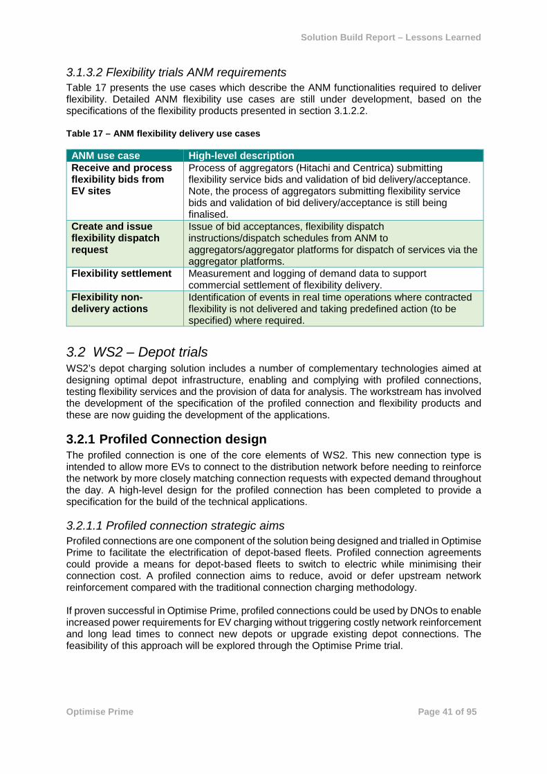
Solution Build Report – Lessons Learned
Optimise Prime Page 41 of 95
3.1.3.2 Flexibility trials ANM requirements Table 17 presents the use cases which describe the ANM functionalities required to deliver flexibility. Detailed ANM flexibility use cases are still under development, based on the specifications of the flexibility products presented in section 3.1.2.2. Table 17 – ANM flexibility delivery use cases ANM use case High-level description Receive and process flexibility bids from EV sites
Process of aggregators (Hitachi and Centrica) submitting flexibility service bids and validation of bid delivery/acceptance. Note, the process of aggregators submitting flexibility service bids and validation of bid delivery/acceptance is still being finalised.
Create and issue flexibility dispatch request
Issue of bid acceptances, flexibility dispatch instructions/dispatch schedules from ANM to aggregators/aggregator platforms for dispatch of services via the aggregator platforms.
Flexibility settlement Measurement and logging of demand data to support commercial settlement of flexibility delivery.
Flexibility non-delivery actions
Identification of events in real time operations where contracted flexibility is not delivered and taking predefined action (to be specified) where required.
3.2 WS2 – Depot trials WS2’s depot charging solution includes a number of complementary technologies aimed at designing optimal depot infrastructure, enabling and complying with profiled connections, testing flexibility services and the provision of data for analysis. The workstream has involved the development of the specification of the profiled connection and flexibility products and these are now guiding the development of the applications.
3.2.1 Profiled Connection design The profiled connection is one of the core elements of WS2. This new connection type is intended to allow more EVs to connect to the distribution network before needing to reinforce the network by more closely matching connection requests with expected demand throughout the day. A high-level design for the profiled connection has been completed to provide a specification for the build of the technical applications.
3.2.1.1 Profiled connection strategic aims Profiled connections are one component of the solution being designed and trialled in Optimise Prime to facilitate the electrification of depot-based fleets. Profiled connection agreements could provide a means for depot-based fleets to switch to electric while minimising their connection cost. A profiled connection aims to reduce, avoid or defer upstream network reinforcement compared with the traditional connection charging methodology. If proven successful in Optimise Prime, profiled connections could be used by DNOs to enable increased power requirements for EV charging without triggering costly network reinforcement and long lead times to connect new depots or upgrade existing depot connections. The feasibility of this approach will be explored through the Optimise Prime trial.

Solution Build Report – Lessons Learned
Optimise Prime Page 42 of 95
3.2.1.2 Profiled connection agreement definition and implementation For the purposes of Optimise Prime, a profiled connection agreement is defined for a given supply at a given site as follows: A connection agreement where the applicable maximum demand limit (in kVA) varies according to the time of day and the season, up to 48 half-hourly time slots per day, with adherence to the profile actively managed through behind-the-meter smart systems and monitored by the DNO. An illustration of the maximum load profile for a winter’s day at a site with a profiled connection agreement is shown in Figure 16. It is envisaged that a different profile could apply in different seasons. Figure 16 – Illustrative standard and profiled connection agreement demand load limit
Figure 17 shows how a profiled connection can enable network reinforcement to be avoided. On the left-hand chart, the expected maximum depot load resulting from a larger EV fleet exceeds the depot’s connection agreement (dashed green line). The resulting load on the network (in purple) exceeds the existing network capacity (dashed line in blue). The vehicle charging schedule is then adjusted to charge during the night rather than when the vehicles return to the depot at the end of their operations. This shift in EV charging changes the timing of depot electricity consumption from the pattern shown by the black curve on the left-hand chart to that of the black curve on the right-hand chart. This has the effect of reducing the load on the network at peak time. This enables the EV charging load to be accommodated within the existing network capacity rather than reinforcing the network (on the right-hand chart, the purple curve is now below the blue dotted line throughout the day). Figure 17 – Site load comparison, with and without a profiled connection agreement

Solution Build Report – Lessons Learned
Optimise Prime Page 43 of 95
Adopting a profiled connection (in red on the right-hand chart) rather than a standard connection agreement (in dashed green) enables the depot operator to increase the depot load above the existing connection agreement level at certain times of day at no additional cost, provided that the depot load is minimised at the times of day when the shared network assets are most constrained. This enables the depot operator to accommodate a larger fleet at the depot than would be possible just by smart charging to fit the EV load within the existing connection agreement capacity.
3.2.1.3 Tools and technical requirements To plan, enact and conform to a profiled connection agreement requires specific technical capabilities to be in place on both the depot operator’s side and at the DNO. The depot operator must be capable of performing the following activities:
• Collect historical site data for the locations in question • Model depot maximum power requirements for various scenarios of fleet electrification • Smart vehicle charging • Flexibility provision • Install any monitoring and control systems as required by the DNO
The DNO must capable of performing the following activities:
• Connection planning • Active network monitoring • Fail-safe mechanism to ensure resilience and reliability of the network
In addition to the standard set of hardware and software tools required for participation in the Optimise prime trials, a specific set of hardware and software tools are required to support the planning and operation of profiled connection agreements. These tools and the interaction between them are shown in Figure 18. Figure 18 – Profiled connection data and electricity flows

Solution Build Report – Lessons Learned
Optimise Prime Page 44 of 95
3.2.1.4 Initial profiled connections trials The first trials of profiled connections will be conducted at Royal Mail sites. These will be trials of pseudo profiled connections imposed artificially at sites where there is no actual constraint on headroom currently, in order to ensure the trials do not present a risk to network integrity. The trials will provide valuable insights into the real operational issues to be considered in managing an EV depot under a profiled connection agreement. The Royal Mail sites for the first pseudo profiled connection trials will be agreed in partnership with Royal Mail. Royal Mail sites currently participating in the Optimise Prime trial include:
• Bexleyheath • Dartford • Islington • Mount Pleasant
• Orpington • Premier Park • Whitechapel
One or more of these sites will be selected for the first trial, with other sites added as experience operating with a pseudo profiled connection grows.
3.2.1.5 Lessons learned In developing the definition of profiled connection agreements, and the approach to implementing them during the Optimise Prime trials, the following key lessons have been learned: Before considering any profiled connection, smart charging offers a significant optimisation potential Optimising the EV charging rates and times at a depot, without any profiled connection, significantly optimises the utilisation of available capacity. At depots where the maximum power requirement from the existing connection agreement is much higher than the existing background depot load, several EV charging events can be accommodated without any network reinforcement need thanks to smart charging. Profiled connections provide the next level of optimisation and savings from smart charging by leveraging the network load diversity potential. A profiled connection does not necessarily translate into no cost at all for the customer A profiled connection aims to reduce, defer or avoid network reinforcements and associated costs. In the event where all wider network reinforcement (shared assets) costs can effectively by avoided thanks to a profiled connection, any sole use asset requiring an upgrade would have to be paid for by the customer. Operational implications for depot operators could present a barrier to adoption If and when profiled connection agreements are made generally available, a failsafe mechanism would be likely to be required by the DNO to enable them to curtail demand at a site if it fails to conform to its agreed profile limits, in order to preserve network integrity for all customers. This could in extreme cases result in reduced ability to complete required vehicle operations due to insufficient vehicle charging. Where vehicle availability is seen by the depot operator as mission critical, they may be less willing to accept this potential risk. The Optimise Prime trials will provide valuable insights into the likelihood of profiles being exceeded, and how depot operators can mitigate this risk.

Solution Build Report – Lessons Learned
Optimise Prime Page 45 of 95
3.2.2 Site Planning Model & Tool The site planning model has been developed to estimate the size of infrastructure and connection requirements of depot customers and to produce a request for a profiled connection that can be considered by the DNO. It was decided at an early stage in the project to separate the development of the ‘model’ (the engine that calculates the infrastructure requirements based on a set of inputs) and the tool (a more user friendly web-based application that allows depot operators to perform the calculations themselves). This is because it was necessary to develop the site planning capability at an early stage in the project to analyse the Royal Mail depots proposed for involvement in the trials. The web interface was not necessary for this task. Plans to develop the web-based tool are described in Section 3.2.2.4.
3.2.2.1 Site planning model strategic aims The primary aims of the site planning model are to:
• Capture the energy requirements of depots, considering their historical electricity consumption and their anticipated EV roll-out
• Optimise energy consumption of depots throughout the day with the use of smart charging and low carbon technologies (LCTs) such as storage and on-site generation to achieve the preferred balance of capital and operational costs for a given investment timescale
• Generate an optimal consumption profile to inform the development of profiled connection agreements between the depots and the appropriate DNO.
These aims will be satisfied by predicting the consequences of fleet electrification in terms of their daily power consumption. The model will be used prior to EV uptake. It will be used to predict the capacity implications of both un-managed and smart charging on capacity requirements. Once capacity predictions and potential connection profiles have been generated by the model, they will be processed by the DNO in meetings with their connections and planning teams so that the benefits or drawbacks of each can be understood in terms of the wider network. This will be used as the basis for eventual profiled connection agreements to be enacted with UK Power Networks.
3.2.2.2 Data sources and configuration The Depot Planning Model draws on specific data from the depot fleet operator regarding the vehicles’ operational requirements, and the electrical demand characteristics of the depot site. This is supplemented with external data sources to support the analysis. Key depot data fields include:
• Vehicle telematics • Historical electricity consumption data per site • Details of existing connection agreements (Authorised Supply Capacity) • Electricity tariff details • Fleet TCO details (if available)
External data sourced by Hitachi to support the analysis includes:
• Vehicle specifications • CP specifications • Insolation values for solar generation assessment

Solution Build Report – Lessons Learned
Optimise Prime Page 46 of 95
• Battery storage and other low carbon technology (LCT) specifications Input from the depot fleet operator is used to configure the model by defining, for each depot:
• Number of EVs to be implemented, and breakdown of make and model • Number of CPs to be implemented, and breakdown of type • Number and parameters of vehicle operational groups (departure time, return time,
number of vehicles of each type)
3.2.2.3 Model outputs The model outputs provide the depot operator with visibility of the potential magnitude of connection capacity that would be required to enable their planned fleet electrification, and whether this could be accommodated within the existing connection capacity. Outputs are provided across four scenarios, representing differing approaches to fleet and depot management: 1. Base
• The aggregated capacity requirements of the CPs are combined with the maximum historical depot load and graphically compared against the existing connection agreement capacity.
• The magnitude of predicted capacity overshoot is calculated, if any.
2. Un-managed • The depot background load for a defined indicative day, typically the day of maximum
historical load for the day type in question (weekday, Saturday or Sunday), is combined with the predicted EV un-managed charging loads (i.e. the vehicle will charge at the maximum rate of the CP until the battery is full or the vehicle is disconnected) for each day type (weekday, weekend) and presented as time-series data.
• The aggregated loads are compared against the existing connection agreement capacity and the magnitude of any predicted overshoot is calculated.
3. EV load minimised • As for un-managed, except EV charging load is distributed across the available time
while the vehicle is plugged in, so as to minimise the EV load in each half hour time period
4. Profile constrained smart • The ability of predicted EV charging load to be managed in order to adhere to the user-
inputted profiled connection constraint pattern of up to 48 half-hourly capacity limits per day will be presented to the user for each day type as ‘feasible’ or ‘infeasible’, according to the constraints imposed on the maximum power drawn together with the operational requirements for the vehicles (range, departure and return times).
• If remaining within the connection agreement capacity is possible, the depot background load profile is combined with the smart EV charging load profile that enables the adherence to profiled connection and presented graphically as time-series data.
• Daily electricity costs are reported, with the specific contribution of EV charging to this cost highlighted.
• The relative weighting of risk and cost parameters can be adjusted to influence the creation of the smart EV charging load profile according to the operational preferences of the depot operator.

Solution Build Report – Lessons Learned
Optimise Prime Page 47 of 95
The aim of the site planning model and its constituent set of scenarios is to guide depot operators through the process of planning for the electrification of their depots. It is intended to enable them to assess the capacity requirements for each depot and install the required EV charging infrastructure in the most cost-effective way. This could include through realising the benefits of profiled connections. Ultimately it is envisaged that the model will demonstrate the potential for significant capacity savings between the base scenario and profile constrained smart scenario, thus highlighting the benefits of using smart charging to adhere to a profiled connection. In consultation with the DNO planners, this should also translate into significant time and cost savings in reaching agreement to proceed with installation of new EV charging infrastructure at a depot. Facilitating this understanding is key to the roll out of profiled connections and encouraging more efficient use of the network.
3.2.2.4 Next steps The model is planned to be migrated into a web-based software tool. This migration will deliver benefits that will be important as the tool transitions from an early version designed to support the needs of the Optimise Prime project to a robust BAU tool for use by all customers planning the electrification of their fleet. In particular, the web-based tool will include:
• Simplified and more intuitive user interface. • Ability to support multiple users across multiple locations simultaneously. • Ability to explore optimal configuration of charging and energy assets (opex and capex)
to support development of a business case for fleet electrification. • Incorporation of new or enhanced features identified through deployment of the Excel-
based model during the Optimise Prime project, for example including a minimum charge rate as part of the constraints within which the optimisation is performed.
The model can be used by the relevant stakeholders throughout GB to support discussions with the relevant DNOs regarding introduction of new EVs at their depots.
3.2.2.5 Lessons learned In developing the site planning model and applying it to analyse the potential electrification of the fleets at a set of Royal Mail depots, several lessons have been learned: Operational schedules There is typically significant variation in actual vehicle movements seen in the telematics data, compared with the expected plan for the depot. For example, it may be expected that three shifts are operated, corresponding to morning, afternoon and all day, whereas in practice only two are observed. It is therefore advised to base the operational schedule used as an input into the site planning model on analysis of historical telematics data, to give an accurate picture of vehicle plug in and out times. Tools and analysis duration required when dealing with telematics Telematics datasets are typically large, with many thousands of rows of data. While possible to analyse in Excel, this can take several hours with larger fleets and is better suited to handling in a dedicated data analysis software package such as Python. Results from modelled scenarios The EV load minimised scenario is of limited value to the depot fleet operator. In practice, the site’s background load (consumption) must always be taken into account when assessing what can be accommodated within the connection capacity, so the profile constrained smart

Solution Build Report – Lessons Learned
Optimise Prime Page 48 of 95
approach is more useful, even if the depot operator’s intention is to manage the fleet within the existing connection capacity, or apply for the depot’s connection capacity to be increased.
3.2.3 Network modelling tool modifications UK Power Networks have two main network modelling tools: DIgSILENT PowerFactory and Ambertree DPlan. During the initial design phase, it was determined that DPlan would require minor modifications to the already developed Timed Connection functionality to support the assessment of profiled connections. For DIgSILENT PowerFactory, the Timed Connections Network Analysis tool previously developed as part of the Timed Connections Software Development project funded via the Network Innovation Allowance (NIA) was deemed to have the necessary functionality to support profiled connection assessment thus no further modification was required. The modification of DPlan to allow network analysis of profiled connections extends the capability already developed under the Timed Connections Software Development project. More specifically, the functionality to assess flexible connections such as timed connections and profiled connection was required to be extended from the HV to the LV network. The main modifications to meet the Optimise Prime requirements were an additional load scaling functionality, a new profiled connection spreadsheet and the ability to deliver a profiled connections report. In addition, the potential for a profiled connection is based on the analysis of historical demand and as there is limited network monitoring on the LV network at present, temporary LV monitoring equipment was installed at secondary substations to which the six LV-connected Royal Mail depot sites are connected to in order to acquire historical network data. The temporary LV monitoring equipment uses iHost as an alternative to OSI-Pi, the existing network data historian platform, for capturing network measurements and thus will require a new interface to import iHost data into DPlan. The functional changes to DPlan that were required to be implemented are as follows: Item 1 – Changes to the timed connections spreadsheet
• Modify UK Power Networks’ existing Timed Connections spreadsheet to allow 48 half-hourly profile for the Optimise Prime MPAN
Item 2 – New LV profiled connection user interface • Create a new menu item (under Reports) for Optimise Prime Headroom • Create a new user interface dialogue to select Optimise Prime MPAN and initiate
Headroom report
Item 3 – LV headroom analysis • Develop a headroom analysis which will check the headroom on the selected nodes.
The headroom will only be for the intact system and will not consider any contingencies (N-1).
Item 4 – LV headroom report • An Excel report showing the results of the headroom analysis.
Item 5 – Importing data from iHost • Data from iHost is required to be imported into the “measurements” attributes. The
data from iHost will be exported in a csv format.

Solution Build Report – Lessons Learned
Optimise Prime Page 49 of 95
• Design, develop and test a spreadsheet to convert the iHost data into a form which can be imported into DPlan using existing DPlan functionality
All functional changes were implemented successfully and User Acceptance Testing of the new DPlan functionality was completed in April 2020 and deployed to BAU subsequently.
3.2.3.1 Lessons learned In the modification of the DPlan tool the following lesson was learned: Allowing time for rigorous testing Sufficient time should be allocated to rigorously test the newly developed functionalities of the software by multiple users to ensure issues are rectified before carrying out the User Acceptance Testing as this will save time and resource during the latter stages of the development process.
3.2.4 ANM system requirements for profiled connections The functional and non-functional requirements for UK Power Networks’ ANM system to manage profiled connections are being develop as part of the project. Profiled connections follows the overall outline architecture described in Section 3.1.3.1.
3.2.4.1 Tools and technical requirements The main technological components that are required for implementation of a profiled connection during the Optimise Prime trial are described in Table 18.

Solution Build Report – Lessons Learned
Optimise Prime Page 50 of 95
Table 18 – Profiled connection technical requirements Technology Type Description Hitachi Depot EV and Flexibility Management
System Performs optimisation of Royal Mail depot EV CPs, identifying schedules that meet profiled and flexibility requirements within specified bounds.
Responsible for:
• Interfacing with, and coordination of, behind-the-meter Depot assets.
• Automated dispatch of Royal Mail depot EV CPs to ensure adherence to the agreed depot demand profile.
• Collecting the data from the trials of profiled connections and flexibility services provision to generate project learnings.
UK Power Networks’ ANM Scheme
System • Monitors and logs impact of profiled and flexibility actions on assets on UK Power Networks’ side of the meter.
• Delivers fail-safe actions to ensure the UK Power Networks distribution network is maintained within safe operating conditions.
• Will be responsible for issuing automated demand turndown instructions (manually generated schedules) and also bid requests to trial the response of Fleet EV to various simulated demand turn down schedules.
ANM Data Store/Historian
System Logs: • Measured demand values from the UK Power Networks
Depot Site RTU, • Demand data coming from the Hitachi IT Platform and
CBS Platform, • Control actions taken by the UK Power Networks ANM
Scheme.
UK Power Networks’ PowerOn DMS
System Provides: • Interface for control room interaction with Timed and
Flexible EV Connections • SCADA monitoring analogues and status indications of
network assets.
Depot EV CPs Device Individual EV CPs at the depot sites – receive and implement charge instructions to deliver agreed charge to EVs.
Depot EV CPCs
Device Individual CP Controllers at the depot sites – receive charge instructions to deliver agreed charge to the EVs and pass this to the CPs.
Depot DER (non EV)
Device Individual DER devices such as flexible demand (non-EV), solar PV or Energy Storage at the depot site
UK Power Networks’ Depot Site RTU
Device UK Power Networks owned RTU located on the UK Power Networks side of meter at depot sites. Used for local monitoring and control actions.

Solution Build Report – Lessons Learned
Optimise Prime Page 51 of 95
3.2.4.2 Use Cases Table 19 presents a series of Use Cases describing the different high-level tasks that deliver the profiled connection functionality. Table 19 – Profiled connection Use Cases Use Case High-Level Description ANM registration of EV Fleet Depots
Registration will include a unique identification (UID) for each depot.
ANM configuration of profiled schedules
Specification and configuration of profiled demand limits for each depot site.
Issue of profiled schedules
Issue of new profiled demand limits for depot sites to Hitachi IT Platform.
ANM monitoring of depot demand
Monitoring of depot demand with respect to the profiled schedules.
ANM observation of profile exceedance
Identification of exceedance of profiled demand limit and issue of warning signal.
ANM takes escalating action
ANM takes action at customer site following extended or high-magnitude exceedance of threshold.
ANM fail-safe ANM enters fail-safe state following loss of communications to Hitachi IT Platform. This use case is required for BAU roll out.
3.2.4.3 Requirements Build The detailed requirements and the delivery plan to build the desired functionality into the ANM system to support the implementation of the profiled connections is currently in progress and specific lessons learned from the build of the functionality into the ANM system will be shared in the subsequent Ofgem Deliverable D3.
3.2.5 Depot Optimisation System The Depot Optimisation System forms part of the TOA sub-system. Initial design work has been completed with a decision made to follow an event-driven loosely coupled microservices architecture utilising a central message broker for internal and cross-sub-system data exchange. This architecture was chosen so that the applications are developed in a modular way, simplifying their re-use after the project is complete. The architecture also allows the different applications to scale independently from one another without having to duplicate services. Figure 19 presents an architectural context diagram for the TOA sub-system. It shows the primary and supporting elements (in pink and grey respectively) of the solution. The three primary software system elements to be developed are:
• Trials Management Application – provides the capability to manage the context that the operational applications are running in, with functions such as tagging captured data with trial identifiers; determining the algorithms used in the optimisation engine; and setting which depots are active in the trial.
• Depot EV Management Application – provides the core capability of the TOA sub-system with an end-user focused operational dashboard and configuration web interface along with a collection of software microservices to manage the depot EV charging optimisation.

Solution Build Report – Lessons Learned
Optimise Prime Page 52 of 95
• Flexibility Management Service – delivers capability to manage the energy demand flexibility use cases along with the integration into UK Power Networks’ ANM system.
Note that although the TOA sub-system can be considered as three distinct primary elements, the underlying software architecture and web application will be built as a single solution sharing common interface design and services. The depot optimisation functionality will take into account a range of data points to inform the process. As outlined in Table 9 in section 2.3.2, this includes:
• Vehicle telematics, including SoC and historical power consumption • Site-wide electricity load • Real-time utilisation data from CPs • Details of existing connection agreements and/or profiled connection • Electricity tariff details • Details of weather and/or external events that may impact demand.
Initial development work on the TOA sub-system, focused on the basic framework and web application, was conducted at the end of 2019. This work was then paused pending the confirmation of the availability of sufficient vehicles for the trials. Detailed design and development recommenced in September 2020 and are expected to be largely complete in early 2021, ready for the trials. Further details of the solution and the lessons learned will be reported in the next deliverable, D3.

Solution Build Report – Lessons Learned
Optimise Prime Page 53 of 95
Figure 19 – TOA Sub-System Context Diagram

Solution Build Report – Lessons Learned
Optimise Prime Page 54 of 95
3.2.6 Flexibility Management WS2 will utilise the overall flexibility methodology outlined in Section 3.1.2. The flexibility available from the vehicles will be aggregated at a depot level. The flexibility technical design work is still being finalised. Figure 19 presents how the concept of Flexibility sits within the TOA sub-system. It is planned that the TOA sub-system will have a direct integration into UK Power Networks’ ANM API over a secure site-to-site VPN. Data exchange will be bi-directional with primary use cases being:
1) Passing plans/bids to UK Power Networks as bids for providing flexibility based on the planned charging schedule
2) Receiving dispatch requests and implementing them by controlling charging 3) Providing settlement data post flexibility event in order to analyse the effectiveness of
flexibility provision.
3.3 WS3 – Mixed trials WS3 is the mixed trial, involving PHVs on the Uber platform. This trial is a data analysis exercise only and does not involve the development of any new tools or applications.
3.3.1 Analytics WS3 utilises the same core analytics and data science environment as the other trials, described in section 2.6. To deliver the analysis required for WS3, a number of models have been designed, and tools used, to infer charge events and visualise them, as well as to model their impact on the distribution network. For Uber trips, data was provided on the start location, end location, as well as a unique (hashed & anonymised) ID of the vehicle that made the trip. For each vehicle, basic metadata about the make, model and year was also made available. Independent data quality checks are performed to make sure that each monthly batch of vehicles is an EV, as well as to curate an independent and separate dataset of battery capacity and ranges for each unique vehicle in the vehicle list. WLTP (Worldwide Harmonised Light Vehicle Test Procedure) ranges are used where available, particularly for newer vehicles, or EPA (Environmental Protection Agency) ratings for American car manufacturers (e.g. Tesla). In rare occasions where these values are not available NEDC (New European Driving Cycle) ranges are used. To predict charge events for the Uber data, the Zap-Map dataset of public CP infrastructure is used, providing basic CP metadata such as location, CP connector speed category (slow, fast, rapid, ultrarapid) and number of connectors (but not connector type).
3.3.1.1 Analysing routes and charging locations It is important to note the project does not receive information about the EV’s current battery level (SoC) at each timestamp (as would happen with telematics data), nor the battery level at the start of the shift. In addition, the data does not reveal the actual route taken by the Uber driver on a particular trip, just the start and end location of that trip. The goal of the analysis, ultimately, is to infer where drivers are charging, and model that current/historical demand on the distribution network. This can then be extrapolated in order to model demand growth as PHV electrification increases, to identify potential locations that require either new or expanded charging infrastructure and to recommend areas where there is capacity on the distribution network to install charging infrastructure.

Solution Build Report – Lessons Learned
Optimise Prime Page 55 of 95
This project team approached this problem using a range of analytical techniques and through the development of a number of assumptions. Firstly, the optimal route that could be taken by a driver between each set of locations was calculated. Then, it was calculated whether, based on the time taken for the journey, a driver could have used each charger close to that route. Where this was the case, the optimal charger was selected. A weighting was applied based on assumed SoC, the amount of charge that could be gained and other factors to predict whether a charge event occurred. The following section explains the analytical process and tools used in greater detail. Due to the nature of the aforementioned data, this was a mathematical modelling exercise (as opposed to a “supervised learning” exercise where verified outputs are used to predict and model). This presented challenges, since only “partially observable” historical data was available. As a result, the team had to make fixed assumptions in order to make headway with the analysis. This highlighted the importance of thinking deeply about the correct data fields in the collection and curation stage of a project, and consulting with data scientists who can assist on how algorithms can be built on top of those fields to achieve the desired aims and outcomes. To overcome this, structural behavioural assumptions were made for the charge event modelling algorithm. When analysing the effect of covariates on a target variable that is not being directly measured (e.g. the effect of weather on battery level), it was necessary to use related/correlated derived variables from the available data fields – the obfuscation of which presents further communication and interpretation challenges, making it more difficult to draw sharper conclusions. In the first instance, a Python based network analysis library (NetworkX) was used to map the entire road network of Greater London (with a 1-mile buffer), defined as the project’s “area of interest” for the analysis. This enabled the calculation of shortest-path distances using standard graph-theoretic techniques. Since there was no historical data, it was assumed that drivers took the shortest path along the road network between observed locations, and began to learn the approximate (average) time it took to travel edges in the graph (and thus roads in the network) according to different times of the day. This modelling assumption does not take into account real time traffic information and road blockages. This road network becomes a reusable data asset for all future Uber analysis. To model predicted charge events, it was assumed that drivers are rational agents with good knowledge of the road network in London. Then, for each event in a driver shift, the probability of a driver charging during that event was decomposed as a function of three elements:
1. The probability a driver should have charged at that moment in time. The higher the probability the driver should charge, the higher the probability they did charge for a specific event. This, too, is an intermediate probability which is modelled as a function of two further variables:
a. Range anxiety: A driver is more likely to charge if their battery level is low (or their “range anxiety” is high)
i. Since specific battery levels for each event are not known, the curated dataset on battery capacities is used together with the range of each vehicle to estimate the drop in battery level since the start of the shift (their range anxiety, being ‘1 – “current battery percentage”’).
ii. It is assumed that the drivers travel the shortest distance along a road network between observed/known locations in the datasets, since complete information on the route they took on trips is not available. The distances of the roads along this route are summed and this information is combined with the expected range of the vehicle, and battery capacity, to estimate the current battery level.

Solution Build Report – Lessons Learned
Optimise Prime Page 56 of 95
b. Current local demand: A driver is more likely to charge if the current local demand at that time is relatively low (opportunistic charging)
i. Historical trip data at a borough level is used to estimate typical demand factors in each region. This is then compared to the current demand at that time from a driver’s perspective.
2. Whether or not it was actually possible for a driver to have charged in a given event: A driver can only charge if it is possible for them to reach a CP between observed locations in the dataset
a. Drivers cannot charge when they are en-route to pick up a passenger, or on a trip with a passenger, but could charge at all other times between their known location logs in the app.
b. It is assumed that drivers take the path of least time via the road network through the CP that maximises the charge they could gain in the available time. If it is not possible to reach a CP and get a charge of at least 1% before making it back to the next observed location in the dataset, it is assumed that a driver could not have feasibly charged in that window.
3. The amount of charge gained from the most optimal CP in the potential charging window: A driver is more likely to have charged in a given window if they yield more charge from a CP (e.g. 20% as opposed to 5%).
a. The model is biased away slightly from drivers charging up to a full battery capacity/charging for too long, under the assumption that drivers are seeking to maximise their time spent doing Uber trips on a given shift.
Since this is an “unsupervised” problem where the outcome the project is trying to explicitly model is not known, a technique called “weak supervision” is used to insert approximate probabilistic labels based on domain-specific heuristics. These labelling functions are crafted using domain expertise and are combined with an underlying graphical model that learns the weighting of these rules based on their prevalence and conflicts with other defined heuristics in the dataset. Traditional supervised learning techniques can then be trained based on the “fuzzy labels” learned by the probabilistic graphical model. All models are trained in Python.
3.3.1.2 Analytical tools and processes For data manipulation, heavy use has been made of multiprocessing capabilities in Python to distribute the algorithms across multiple cores for faster runtimes. This includes the base multiprocessing Python module for the parallelisation of custom functions across multiple CPU cores that do not uniquely involve data table manipulations (such as road network calculations), as well as a Ray/Dask backend to the Pandas Library using Modin for heavy data table processing. The typical data science Python stack for algorithm development has been used. To visualise the models, Python based geospatial analysis tools are used, built on top of open-source WebGL frameworks for external communication of results (kepler.gl, deck.gl) and Geopandas (a Python based tool for analysing spatial data) for internal and backend processes. For plotting of time series data (e.g. utilisation profiles, or how certain values vary over the day), the project uses time series widget in Kepler (if the underlying data is geospatial) or Python plotting libraries. Typically this is Matplotlib/Seaborn for static visualisations, and Plotly/Bokeh for dynamic visualisations. Static visualisations can be created for external communication while dynamic visualisations are used as internal tools to aid data exploration and result interpretation.

Solution Build Report – Lessons Learned
Optimise Prime Page 57 of 95
All code/data assets (including raw source code, functions, models, data tables and visualisations) are stored as part of a centralised data science library for the Optimise Prime project, backed up using Gitlab, PostgreSQL and S3-like buckets on HCP. WS3 presented additional requirements regarding personal data protection, and thus the project had to define rigorous processes for data handling. From an analytics perspective, data could only be shared if it is aggregated to a level where no single trip can be identified. There are two ways of doing this aggregation: spatially and temporally. Custom scripts have been built that ensure the rendering, or otherwise saving, of any individual rows of data cannot leave the analytics platform, and only specifically generated, suitably aggregated plots can be exported from the platform where required. Such cases are peer reviewed by the Data Science and Business team to ensure data anonymity. Optimise Prime’s internal data science library includes logging capabilities, to ensure traceability of data flows around the platform when using the library, and logs are stored in a central place.
3.3.1.3 Learnings from WS3 analytics The following learning was derived from WS3 analytics. Accuracy and other considerations regarding public CP data From the initial analysis of Uber journeys against public CP data, it became apparent to the project that there is a lack of a fully comprehensive and authoritative source of charger locations and details. While the project uses data from Zap-Map, identified as the best available source, data quality issues such as duplicate entries and lack of ‘taxi only’ flags have been identified. This is thought to be largely due to the fact that Zap-Map relies on a wide range of sources, including crowdsourcing, to gather its data which makes it difficult to validate all information. Where issues have been identified, these have been reported to the data provider and the project team continue to monitor for data quality issues that may impact trial conclusions. It is also not possible to systematically exclude CPs where access may be subject to high fees (such as those located within some Central London car parks). Where possible we have manually excluded such locations from the analysis where Uber have indicated that specific locations are avoided by their drivers on specific grounds such as cost.

Solution Build Report – Lessons Learned
Optimise Prime Page 58 of 95
4 Trials methodology The high-level design of the trials was published in Deliverable 1. This section provides further detail on the Methodology that will be used for the trials. The trials design continues to evolve as the Project Partners and Participants confirm details of their infrastructure and as lessons are learned from preliminary trials activity. To ensure that the trials are statistically significant, the project has engaged and external consultant to review the trials methodology, details of that review can also be found in this section.
4.1 Updates from Deliverable D1 The trial designs described in Deliverable D1 set out the overarching objectives and sub-objectives for each of the three trials. Development of the trial methodology since then has focused on designing specific experiments – sets of data gathering and analysis tasks – the execution of which will deliver insights required for each sub-objective, and by extension, the main trial objectives.
4.2 Definition and scheduling of experiments Each sub-objective may have one or more experiments associated with it, as shown in Figure 20. The focus of trials planning work since D1 has been to define a set of experiments for each trial, and plan a series of executions of those experiments over the 12 months up to the start of the formal trial period in July 2021.This plan will form the basis for the approach of the formal trials, although it will be subject to revisions according to lessons learned in running the first experiment executions. The experiments have been designed to be iterative and are planned to all be run multiple times during the preliminary implementation phase, allowing for lessons to be learned from the first runs and applied to the execution approach before the formal trials begin. Additionally, this iterative approach allows for ongoing refinement of the data analysis approach as the datasets for each of the trials grow with increasing vehicle numbers. Experiment executions have been planned to an initial 12-month schedule, allowing gradual ramp up of complexity as the technical data gathering systems become available, and control systems are implemented. Each execution is associated with the set of data engineering and data analysis features that are required to deliver it. For each trial, a specific set of data science models and analysis approaches will be developed according to the data science methodology, enabling insights and conclusions to be drawn from the data. It is envisaged that the iterations of experiment will create a sample size sufficient to ensure statistical robustness in drawing conclusions from the analysis. This will be confirmed as the datasets are developed, with reference to the proposed statistical approach that has been developed for the trials.

Solution Build Report – Lessons Learned
Optimise Prime Page 59 of 95
Figure 20 – Trials objective deconstruction
4.2.1.1 Experiment definition Within Optimise Prime trials, an experiment is defined as: The set of data collection, analysis and evaluation activities required to support or reject a hypothesis related to one or more sub-objectives. Each experiment will require a set of data gathering systems to be in place to capture the raw data, and may also require specific data analysis models to be developed to process the raw data and enable insights to be drawn from it, as illustrated in Figure 21. Figure 21 – Illustrative experiment components

Solution Build Report – Lessons Learned
Optimise Prime Page 60 of 95
The data sources required to be evaluated in the trials are common across many of the sub-objectives. Consequently, in designing the experiments, it has been pragmatic to group together certain activities that will support multiple sub-objectives. This simplifies repetition of the experiments as new data is brought in over the course of the trials: once the data gathering and analysis processes are defined for the experiment, it can be re-run easily. It also enables these models to be used in a modular way – analysis capabilities developed for earlier experiments become the foundations for later experiments. In all cases, experiments have been mapped to the sub-objectives to ensure that their completion will deliver the agreed learnings of the project. Each experiment is planned to be executed multiple times. For some of the experiments, these repeated executions enable the analysis to be updated as new data comes in from the vehicles and CPs included in the trials. In all cases, repeated executions allow for any operational or technical challenges that are revealed in the first iterations to be overcome and accommodated within a revised design ahead of the formal trials.

Solution Build Report – Lessons Learned
Optimise Prime Page 61 of 95
4.2.1.2 Trials experiments – WS1 (Centrica) The planned experiments for the WS1 home-based vehicle trial with Centrica’s British Gas fleet are listed in Table 20, together with the relevant mapping to trials sub-objectives. Table 20 – WS1 (Centrica) trial experiments and sub-objective mapping Experiment number
Hypothesis Activity summary Related sub-objectives
CEN_Ex_01 The relative contribution of unmanaged charging of charge-at-home EVs to overall home electricity consumption can be predicted using analysis of ICEV operation
Analysis of historical ICEV fleet telematics data to predict likely charge requirements for EV fleet. Correlation of predicted EV charge requirements with actual charge demand values recorded from the operational EV fleet. Analysis of unmanaged EV charging contribution to total home energy use.
1.1 Understand the operational requirements of return-to-home commercial vehicles 1.2 Model and validate EV charging profiles 1.3 Model and validate contribution of EV charging to home energy consumption
CEN_Ex_02 The relative contribution of 'smart' charging of charge-at-home EVs to overall home electricity consumption can be predicted using analysis of ICEV operation and unmanaged EV charging behaviour
Prediction of load from smart charging EVs based on analysis of ICEV fleet operation and unmanaged EV charging. Optimise charging schedule based on predictions from ICEV and unmanaged EV charging observation data and deploy to CPs. Correlate predicted values with observed smart charging load from operational EV fleet. Analyse contribution of smart charging EVs to total home energy use.
1.3 Model and validate contribution of EV charging to home energy consumption
CEN_Ex_03 EV charging demand will be influenced by weather and seasonal events
Model impact of external factors such as season, weather, day of the week, events calendar on EV charging load, and correlate to observed values.
1.2 Model and validate EV charging profiles 1.3 Model and validate contribution of EV charging to home energy consumption

Solution Build Report – Lessons Learned
Optimise Prime Page 62 of 95
Experiment number
Hypothesis Activity summary Related sub-objectives
CEN_Ex_04 Charge-at-home EV charging causes low magnitude, local stress on the LV distribution network but poses a more significant effect at higher voltages due to network clustering
Modelling of location and magnitude of network constraints resulting from charge at home EV fleets. Analysis of the relative impacts resulting from unmanaged and smart charging at different levels of fleet electrification. Analysis of relative impacts at LV and HV level.
1.4 Model and validate the effect of charge-at-home EV loads on distribution network infrastructure 1.5 Consider future scenarios for EV uptake and consider effects on the distribution network 1.6 Translate simulated and measured network effects into infrastructure upgrade requirements
CEN_Ex_05 Charge-at-home commercial vehicle electrification has higher DNO cost implications than depot-based vehicle electrification
Analysis of cost implications due to network reinforcement resulting from additional load from charge at home EVs.
1.7 Translate anticipated upgrade requirements into DNO costs
CEN_Ex_06 Separate metering of commercial EV charging will save money for both the driver and the fleet operator
Prediction of energy costs from charge at home EV fleets at different levels of fleet electrification, for unmanaged and smart charging. Analysis of cost impact of different energy tariffs (e.g. commercial and domestic). Correlation of predicted values with observed data.
3.1 Understand the impacts of EV uptake on Centrica fleet TCO
CEN_Ex_07 The TCO of charge-at-home EVs will be higher than ICEVs due to higher upfront costs
Create a TCO model for a given number of EVs and compare with a TCO model for an equivalent number of ICEVs. Analyse impact of factors such as purchase cost, mileage, maintenance, energy cost on relative TCO values for each fleet. Correlate predictions with observed values from operational EV fleet.
3.1 Understand the impacts of EV uptake on Centrica fleet TCO

Solution Build Report – Lessons Learned
Optimise Prime Page 63 of 95
Experiment number
Hypothesis Activity summary Related sub-objectives
CEN_Ex_08 Distribution network constraints caused by charge-at-home commercial EVs will be minimised through combination of smart-charging and time of use (ToU) tariffs
Predict magnitude, location and timing of loads resulting from charging of return to home EV fleets and correlate to incidences of network constraints. Analyse impact of level of fleet electrification and charging approach (unmanaged vs smart) on distribution network constraints. Correlate predictions to observed values.
3.2 Compare the effects of unmanaged charging and aggregator managed-charging on the distribution network
CEN_Ex_09 Charge-at-home vehicles with reactive operational behaviour with large distances/heavy loads are inappropriate for electrification
Analyse the TCO impact of fleet electrification for different operational groups (e.g. planned vs reactive schedules; high vs low payload; urban, sub-urban or rural routes). Assess differences in driver satisfaction following electrification for each group.
3.3 Develop future strategies for return-to-home commercial vehicle electrification 4.4 Evaluate the operational limitations to flexibility provision
CEN_Ex_10 The availability for charge-at-home EVs to be utilised for flexibility services can be predicted from 'smart' and unmanaged charging experiments
Predict magnitude and availability of flexibility services that could be provided by charge at home EV fleets based on observed unmanaged and smart charging behaviour.
4.1 Model and verify the flexibility available from charge-at-home commercial EVs 4.2 Determine DNO flexibility needs
CEN_Ex_11 Flexibility from charge-at-home EVs will be best suited to long-term weekend contracts or short-term over-night contracts
Analyse the value available from provision of flexibility services from charge at home EV fleets (£/kW). Assess the impact of external variables such as day of the week, season, weather on value for different levels of fleet electrification. Correlate flexibility potential with magnitude of demand from the DNO, and relative costs and benefits to each. Analyse practical limitations to flexibility provision (e.g. driver behaviour).
4.3 Predict value of flexibility from charge-at-home EVs to fleet/DNO given different market models 4.4 Evaluate the operational limitations to flexibility provision

Solution Build Report – Lessons Learned
Optimise Prime Page 64 of 95
Experiment number
Hypothesis Activity summary Related sub-objectives
CEN_Ex_12 Centrica drivers will prioritise operability over technological complexity of solution
Create a survey and administer to Centrica drivers. Analyse driver attitudes to use of EVs for return to home fleets based on survey responses
5.1 Evaluate driver satisfaction with EV uptake 5.3 Evaluate satisfaction with separate EV metering
CEN_Ex_13 Centrica as a fleet operator will prioritise TCO minimisation above operational aspects
Create a survey and administer to Centrica fleet operator(s). Analyse fleet operator attitudes to charge at home fleet electrification, including relative importance of TCO and operational considerations based on survey responses.
5.2 Evaluate the satisfaction of fleet operators with EV uptake 5.3 Evaluate satisfaction with separate EV metering
CEN_Ex_14 Charge-at-home commercial EV fleets are not attractive to aggregators for flexibility provision
Create a survey and administer to aggregator (CBS) representative. Analyse aggregator attitudes to electrification of return to home fleets, particularly with respect to the opportunity for flexibility provision, based on survey results.
5.4 Evaluate aggregator satisfaction with commercial EV flexibility provision
For each of the experiments, a number of executions have been planned over a 12-month period, although these are subject to change according to the availability of data from Centrica. Based on the learnings from these trial executions, a further plan will be developed to cover the formal 12 month trial period, from July 2021, when all vehicles will be on the road.

Solution Build Report – Lessons Learned
Optimise Prime Page 65 of 95
4.2.1.3 Trials experiments – WS2 (Royal Mail) The planned experiments for the WS2 depot-based vehicle trial with Royal Mail’s fleet are listed in Table 21, together with the mapping to the associated sub-objectives. Table 21 – WS2 (Royal Mail) trial experiments and sub-objective mapping Experiment number
Hypothesis Activity summary Related sub-objectives
RM_Ex_01 The impact of unmanaged EV charging on Royal Mail depot electricity demand can be predicted using analysis of ICEV operation
1. Predict and develop indicative daily energy requirements (kWh) and plug-in/plug-out times for each depot and operational schedule, based on analysis of ICEV data (vehicle mileage/fuel spending, telemetry data, payload, etc.) and external factors (time of year, weekend/weekday, weather, events, etc.) prior to depot electrification. 2. Install charge-points and track plug-in/plug-out times, comparing them to predictions. Monitor vehicle state of charge (SoC) at plug-in and plug-out times and charge event time/magnitude with chargers operating in unmanaged mode. Develop indicative energy requirements for each region of vehicle operation based on learnings from unmanaged charging EVs. Create and model EV charging load profiles based on unmanaged charging events incorporating different CP speeds. 3. Compare load profile predictions with realised aggregated load profiles, analyse discrepancies and update models. Determine the minimum plugged-in unmanaged charging time needed to meet operational energy requirements. Model aggregated EV charging profiles that avoid peak hours/pricing in absence of depot background load, compare EV load to historical depot load.
1.1 Understand the operational requirements of Royal Mail EVs 1.2 Model and validate EV charging profiles for each level of technological complexity

Solution Build Report – Lessons Learned
Optimise Prime Page 66 of 95
Experiment number
Hypothesis Activity summary Related sub-objectives
RM_Ex_02 The impact of 'smart' EV charging on Royal Mail depot electricity demand can be predicted using analysis of ICEV operation and unmanaged EV charging behaviour
1. Develop and test predictive capabilities for energy requirements, plug-in/plug-out time and SoC given the implementation of 'smart' charge-points. Monitor the time and magnitude of charge events once charge-points are operating to meet a profile, compare to the dispatched charging orders. Create and model EV charging load profiles based on charging events monitored in 'depot managed' mode including different charger speeds. 2. Compare predicted aggregated charge-point load (from unmanaged charging mode) with that realised, analyse discrepancies and update models.
1.1 Understand the operational requirements of Royal Mail EVs 1.2 Model and validate EV charging profiles for each level of technological complexity
RM_Ex_03 EV charging demand will be influenced by external factors such as weather and seasonal events
Predict EV charging load profiles assuming unmanaged charging, varying the scale of EV uptake, based on observed performance across a range of external variables (weather, weekday/weekend, payload, etc.).
1.2 Model and validate EV charging profiles for each level of technological complexity

Solution Build Report – Lessons Learned
Optimise Prime Page 67 of 95
Experiment number
Hypothesis Activity summary Related sub-objectives
RM_Ex_04 The load profile of Royal Mail depots can be predicted based on the degree of electrification of the fleet and charging mode adopted (unmanaged or 'smart')
1. Collect electricity consumption data (kWh) from each depot for the two years prior to the installation of charge-points and build indicative load profiles for each depot based on day type, season, weather, events, including corresponding unmanaged charging loads. Scale the depot load according to the proportion of the fleet electrified and determine the point at which the connection agreement is violated, assess whether the proposed number of EVs for the depot under consideration will violate the connection agreement given unmanaged charging. Select number of EVs for unmanaged charging trial. 2. Monitor half-hourly depot connection point loads given unmanaged charge-point operation and compare to those predicted prior to charge-point installation. Analyse discrepancies and update models. 3. Build optimal load profiles for each depot for day type and season including 'depot managed charging' EV loads and loads from installed LCTs, based on electricity cost using depot structure/TOU tariff and based on maximising the distance from connection agreement limit. 4. Monitor depot connection point loads given the uptake of 'depot managed charging' to meet a set profile and compare to those predicted from unmanaged charging experiments. Analyse discrepancies and update model to include 'depot managed charging' predictive capabilities. Develop and test model (dependent on EV energy requirements, weather, type of day, season, etc.) given 'depot managed' charging EVs. Build load profiles for 100% electrification of depot vehicles using 'depot managed' charging.
1.3 Model and validate load profiles from electrified depots

Solution Build Report – Lessons Learned
Optimise Prime Page 68 of 95
Experiment number
Hypothesis Activity summary Related sub-objectives
RM_Ex_05 The impact of installation of other LCTs on load profiles of electrified depots can be predicted
Model indicative load profiles for each depot for day type and season including unmanaged charging EV loads, with varying solar generation loads and battery storage capacity. Monitor solar production and battery imports/exports (if installed).
1.2 Model and validate EV charging profiles for each level of technological complexity 1.3 Model and validate load profiles from electrified depots

Solution Build Report – Lessons Learned
Optimise Prime Page 69 of 95
Experiment number
Hypothesis Activity summary Related sub-objectives
RM_Ex_06 The need for network reinforcement resulting from depot fleet electrification can be mitigated through profiled connections
1. Gather depot connection details (connection agreement capacity, position in network) and details (name, location) of network infrastructure that may be associated with delivering power to each depot prior to charge-point installation. Collect feeder load capacity for each depot (kVA) and historical electricity loading data of the feeder (kVA/kW) for those with multiple connections, for the period prior to charge-point installation. Collect relevant substation max load capacity (kVA) and historical electricity loading data (load factor, max peak loads), for the two years prior to charge-point installation. Identify DNO concerns surrounding EV charging (voltage stability, power quality) prior to charge-point installation. 2. Overlay depot load profiles with unmanaged charging EVs with relevant feeder and substation load profiles, and then with 'depot managed charging'. Translate each individual depot load to percentage of capacity used in local network infrastructure (feeders/substations). Identify time periods with maximum capacity usage and determine percentage contribution by the depot in these time periods. Determine trends in peak loading times (weather, season, events) and in percentage contribution from depots to peak loading periods for unmanaged charging and 'depot managed charging' profiles. Considering data collection across all depots and network infrastructure, relate reductions in capacity (or spikes in loading) with other network indicators (e.g. hot-point temperature, voltage). 3. Assess potential load profiles generated by learnings from unmanaged charging trials and select the depot load profile that mitigates undesirable network effects for a basis of the profiled connection. Determine the amount of capacity released by introduction of profiled connections. Identify HV/EHV transformers which are in the direct network for each depot prior to charge-point installation and use methods such as loss of lifetime analysis to determine transformer upgrade requirements based on data collected in unmanaged charging trials.
1.4 Model and validate the effect of depot load on local distribution network infrastructure in the region surrounding the depot at the same voltage level 1.5 Predict the effect of depot load on distribution network infrastructure at higher voltage levels than the depot connection 1.7 Translate simulated and measured network effects into infrastructure upgrade requirements

Solution Build Report – Lessons Learned
Optimise Prime Page 70 of 95
Experiment number
Hypothesis Activity summary Related sub-objectives
RM_Ex_07 LV distribution network impacts resulting from depot EV charging can be predicted
1. Identify variables available for monitoring at relevant substations and at the depot connection point (transformer hot-point temperature, voltage, current, (re)active power flows, etc.) prior to charge-point installation. 2. Record voltage and current at depot connection and at relevant network infrastructure, throughout unmanaged charging trial duration. Monitor, record and measure all the variables identified as required to monitor the effects of depot electrification under different models (unmanaged, depot managed and depot managed and flexibility). Overlay depot load profiles with unmanaged charging and with 'depot managed charging' EVs with relevant feeder and substation load profiles. 3. Model network effects with high penetration of EVs at depots assuming 'depot managed charging'. Extrapolate findings from Royal Mail depots to other depots and predict effects on entire distribution network. Use methods such as loss of lifetime analysis to determine transformer upgrade requirements based on data collected in 'depot managed charging' trials. Communicate measured network indicators from unmanaged charging and 'depot managed charging' trials to DNO (peak loads, min/max voltage, min/max current, etc.) and request update on reinforcement timelines.
1.4 Model and validate the effect of depot load on local distribution network infrastructure in the region surrounding the depot at the same voltage level 1.5 Predict the effect of depot load on distribution network infrastructure at higher voltage levels than the depot connection 1.6 Consider future scenarios for EV uptake and model effects on the distribution network 1.7 Translate simulated and measured network effects into infrastructure upgrade requirements

Solution Build Report – Lessons Learned
Optimise Prime Page 71 of 95
Experiment number
Hypothesis Activity summary Related sub-objectives
RM_Ex_08 HV distribution network impacts resulting from depot EV charging can be predicted
Monitor physical attributes of HV/EHV transformers throughout the duration of unmanaged charging and 'depot managed charging' trials. Associate lower voltage sub-station constraints with higher voltage substation constraints from data collection. Extrapolate findings from Royal Mail depots to other depots and predict effects on entire distribution network.
1.5 Predict the effect of depot load on distribution network infrastructure at higher voltage levels than the depot connection 1.6 Consider future scenarios for EV uptake and model effects on the distribution network 1.7 Translate simulated and measured network effects into infrastructure upgrade requirements
RM_Ex_09 Depot vehicle electrification has lower DNO cost implications than return-to-home vehicle electrification
Apply DNO costing method for bringing reinforcements forward/delaying reinforcements to evaluate network benefits/costs associated with unmanaged/depot managed charging of EVs. Compare relative cost impact across infrastructure (LV/HV/EHV).
1.8 Translate anticipated upgrade requirements into DNO costs

Solution Build Report – Lessons Learned
Optimise Prime Page 72 of 95
Experiment number
Hypothesis Activity summary Related sub-objectives
RM_Ex_10 EV load shifting can enable adherence to a profiled connection without exposing the DNO to unacceptable risks
1. Using learning from unmanaged charging experiments, prove EV charging load-shifting can be used to adhere to a profiled connection (i.e. prove EVs have flexibility and make up a large percentage of depot load). Run sensitivity analysis on the load-profile model used to generate potential depot managed-charging load profiles (EV energy requirements, depot electricity consumption, solar generation). Catalogue scenarios which would result in the profiled connection agreement being breached (based on load profile modelling using unmanaged charging learnings). Model the influence of proportion of fleet electrified on the ability to adhere to a profiled connection (based on learnings from unmanaged charging trial). Artificially lower the profiled connection that is inputted into optimisation tool until the EV charging schedule results in vehicle charge-level being within 5% of what is operationally acceptable (chargers in depot managed charging mode). Determine the size of breach of profiled connection required to threaten network infrastructure. 2. Determine patterns in events that approach/breach the connection agreement maximum during 'depot managed charging' trials. Determine optimisation system behaviour when close to breaching profiled connection agreement. Determine a sensible safety margin for profiled connections overload profiles using learning from 'depot managed charging' trials.
2.1 Explore risks associated with roll-out of profiled connections for the DNO

Solution Build Report – Lessons Learned
Optimise Prime Page 73 of 95
Experiment number
Hypothesis Activity summary Related sub-objectives
RM_Ex_11 Profiled connection agreements are financially advantageous to both depot operator and DNO
Associate breaches in profiled connection with network cost using models. Predict costs to Royal Mail if a £/kW breach charge in combination with a cheaper connection cost (soft profiled connection) with a lower safety margin was implemented, and if a hard profiled connection was implemented with a more expensive one-off connection cost (based on modelled 'depot managed charging' load profiles). Submit profiled connection (hard/soft) applications to DNO prior to 'depot managed charging'. Submit profiled connection application for 100% electrification of depot prior to 'depot managed charging' (hard/soft). Calculate yearly connection cost with profiled connections (hard/soft) once 'depot managed charging' is implemented.
2.2 Develop pricing strategy for profiled connections

Solution Build Report – Lessons Learned
Optimise Prime Page 74 of 95
Experiment number
Hypothesis Activity summary Related sub-objectives
RM_Ex_12 Profiled connection agreements and flexibility services reduce fleet TCO
1. Estimate, prior to charge-point installation: vehicle (EV/ICEV) purchasing costs, unmanaged and 'smart' charge-point purchasing costs, electrical infrastructure costs, installation costs, asset insurance costs, asset depreciation, fuel expenditure on non-EVs and maintenance costs. Estimate electricity costs (energy) based on depot tariff structure and TOU tariff structure for unmanaged load profiles. Calculate EV and 'smart' charge-point purchasing costs. 2. Calculate, post charge-point installation: electrical infrastructure costs, installation costs and asset insurance costs. Update asset depreciation and maintenance costs projections periodically post charge-point installation. Calculate electricity costs (energy) based on depot/ToU tariff structure for unmanaged/depot managed/depot managed and flexibility load profiles. Estimate: connection costs for each level of electrification, software costs for 'smart' optimisation systems/'smart' optimisation systems with flexibility trading capabilities and vehicle taxation costs before and after EV uptake (including ULEZ). 3. Submit profiled connection application for depot based on unmanaged/'depot managed' load profiles (expected percentage of EVs). Submit standard connection application to DNO based on unmanaged charging load profiles (expected percentage of EVs). Submit profiled connection application for depot based on unmanaged/'depot managed' load profiles (100% electrification). Submit flat profiled connection application to DNO based on unmanaged charging load profiles (100% electrification). Estimate and calculate flexibility services revenue.
2.3 Evaluate the impact of profiled connections and flexibility on TCO
RM_Ex_13 Profiled connection agreements reduce lead time and costs to electrify fleets
Quantify cumulative months across depots saved by avoidance of upgrades due to adherence to a profiled connection. Translate months of reinforcement saved from implementation of profiled connections into EV uptake rates and carbon benefits.
2.4 Determine reduction in lead-time for electrifying depots

Solution Build Report – Lessons Learned
Optimise Prime Page 75 of 95
Experiment number
Hypothesis Activity summary Related sub-objectives
RM_Ex_14 Smart electrification strategies reduce DNO costs
Compare average 'depot managed'/unmanaged electrification depot load profiles across depots. Compare network effects of 'depot managed'/unmanaged electrification across depots. Compare network costs at end of trials for associated with each depot ('depot managed'/unmanaged). Compare network costs for simulated 100% electrification of each depot ('depot managed'/unmanaged).
3.1 Compare levels of electrification for their effects on the network
RM_Ex_15 Optimisation of depot LCTs with the EV fleet creates additional benefits
Translate modelled LCT depot load profiles into electricity costs assuming solar consumed behind-the-meter is free of charge with/without feed-in-tariffs or licenced supply arrangement in place/assuming purchased solar (for both flat and profiled connection agreements). Determine value in battery storage based on 'depot managed charging' load models. Compare the impact on TCO for LCTs based on 'depot managed charging' load models. Estimate carbon savings enabled by LCTs. Estimate the percentage load overlap between solar generation and Royal Mail EV charging demands. Estimate cost savings associated with V2B charge-point capability and revenue streams associated with V2G charge-point capability (for both flat and profiled connection agreements). Compare the network impacts of depots with/without LCTs by comparing load profiles for both 'depot managed'/unmanaged cases.
3.2 Determine the value in LCT integration into depots for fleet operators 3.3 Determine the value in LCT integration into depots for the DNO

Solution Build Report – Lessons Learned
Optimise Prime Page 76 of 95
Experiment number
Hypothesis Activity summary Related sub-objectives
RM_Ex_16 The availability for depot based EVs to be utilised for flexibility services can be predicted from 'smart' and unmanaged charging experiments
Model all possible EV charging schedules that would ensure operational requirements are met and connection agreements are not violated (for both flat and profiled connection agreements). These profiles will show the potential for manipulating EV charging schedules away from that which provided the optimum solution of the objective function set by depot operators (e.g. electricity cost minimisation). Ignoring profiled connection limitations (flat profiled connection agreement), model the maximum magnitude of response available at each time whilst adhering to operational requirements, then repeat adhering to profiled connection limitations. Predict trends in flexibility availability/cost given simulated flat/profiled connection agreement (time of day, month, events). Determine patterns in flexibility availability/cost through initiation of flexibility requests given adherence to flat connection agreement. Evaluate predictive capabilities for depot flexibility availability over different time scales (i.e. how long before the fact can flexibility be accurately predicted). Enumerate instances where the depots fail to deliver flexibility ordered by DNO (simulated or contracted).
4.1 Model and verify the flexibility available from electrified depots

Solution Build Report – Lessons Learned
Optimise Prime Page 77 of 95
Experiment number
Hypothesis Activity summary Related sub-objectives
RM_Ex_17 Standard connection agreements allow for higher availability of cheaper flexibility compared to profiled connection agreements
Estimate average costs associated with shifting the charging loads (to give maximum response at each time) based on depot/ToU tariff structure given simulated flat/profiled connection agreement. Determine best tariff structure to minimise the costs of available flexibility for depot operator, the carbon costs (if any) associated with flexibility, and how price for depot flexibility varies with proximity to the time of the flexibility event (value in planning) given adherence to flat connection agreement. Determine patterns in flexibility availability/cost through initiation of flexibility requests given adherence to profiled connection agreement. Given the flexibility available in the EV charging schedule, determine the depot electricity tariff structure that best minimises the cost of load shifting (flat, peak/off-peak, three tier TOU). Determine carbon costs (if any) associated with flexibility, and how price for depot flexibility varies with proximity to the time of the flexibility event (value in planning) given adherence to a profiled connection agreement. Compare the percentage of installed capacity typically available for flexibility at different times of day for flat/profiled connection agreements. Determine which vehicle operation region provides the highest % of installed capacity for flexibility for both flat and profiled connection agreements.
4.1 Model and verify the flexibility available from electrified depots

Solution Build Report – Lessons Learned
Optimise Prime Page 78 of 95
Experiment number
Hypothesis Activity summary Related sub-objectives
RM_Ex_18 Flexibility will only be a viable option to depots if procured on long-term contracts for weekend or over-night periods
Compare the viability of long-term/short-term flexibility contracts given flat/profiled connections. Compare depot flexibility availability/price with Centrica and Uber flexibility availability/price. Compare the best reward structure for flexibility provision from fleet operator perspective for both flat/profiled connection agreements. Evaluate predictive capabilities for flexibility availability from depot based EVs over different time scales.
4.1 Model and verify the flexibility available from electrified depots 4.3 Predict the value of flexibility from electrified depots to the fleet operator/ DNO given different market models

Solution Build Report – Lessons Learned
Optimise Prime Page 79 of 95
RM_Ex_19 DNO current flexibility requirements are unlikely to be met by depot based EVs
Compare the percentage of flexibility agreements that are not met due to operational limitations for flat/profiled connection agreements. Determine quantity of flexibility provided which is not a direct result of EV charging load shifting for both flat and profiled connection agreements. Enumerate instances where the depots fail to deliver flexibility ordered by DNO (simulated or contracted). Determine the min. time taken (response speed) to achieve max. flexibility delivery in response to a DNO communicated need for both flat/profiled connection agreements. Determine how well the prices for flexibility compare to successful bids within existing flexibility markets. Compare constraint patterns across associated network infrastructure throughout unmanaged/depot managed charging trials. Based on constraint patterns, determine magnitude and duration of flexibility required for appropriate alleviation. Based on predictive models generated during project, identify constrained areas/times of day of the network which may require flexibility services given high penetration of EVs. Calculate potential reinforcement cost offset by provision of maximum available flexibility from depot based commercial EVs. Determine maximum magnitude of reward for providing flexibility services (£/kW). Optimise fleet flexibility provision to maximise network savings and minimise cost to fleet. Bid for flexibility required by DNO for zones of overlap with depots (if they exist). Given flexibility sold to DNO or understanding of network constraints, manipulate EV charging schedules to achieve the flexibility requirements. Record all relevant variables (e.g. voltage, current, temperature etc.) at depot connection throughout 'depot managed charging and flexibility' trial duration. Compare the market mechanisms which appear to best suit the nature of flexibility required by the DNO (how far ahead of time can flexibility requirements be predicted? Do flexibility requirements reliably fall within certain time-bands?) to those uncovered in flexibility projects external to the trial.
4.1 Model and verify the flexibility available from electrified depots 4.2 Determine DNO flexibility needs 4.3 Predict the value of flexibility from electrified depots to the fleet operator/ DNO given different market models 4.4 Evaluate the operational limitations to flexibility provision

Solution Build Report – Lessons Learned
Optimise Prime Page 80 of 95
Experiment number
Hypothesis Activity summary Related sub-objectives
Enumerate flexibility interruptions due to human interaction. Determine drivers range anxiety (/10) before and after flexibility services were offered by the depot. Evaluate physical limitations to fleet flexibility provision, e.g. availability of parking for required hours of charging.
RM_Ex_20 Royal Mail depot staff will favour operability over technological sophistication of the solution
Enumerate incidences of inadequate charge. Survey drivers throughout trial gauging attitude towards EVs at quarterly intervals throughout project duration. Survey depot operators throughout trial gauging attitude towards EVs at quarterly intervals throughout project duration and gauging attitude towards space availability before and after implementation of EVs. Enumerate routes which were deemed inappropriate for EV operation. Enumerate incidences of vehicles out for maintenance for both ICEVs and EVs. Survey depot operators throughout trial gauging attitude towards optimisation software at quarterly intervals throughout project duration. Enumerate incidences of incompatibility in end to end testing and document their resolution. Enumerate incidences of depot operator over-riding charging schedules.
5.1 Evaluate the satisfaction of drivers with EV uptake 5.2 Evaluate the satisfaction of depot operators with EV uptake 5.3 Evaluate the use of smart software systems to ensure business-as-usual conditions
For each of the experiments, a number of executions have been planned over a 12-month period, although these are subject to change according to the practicality of running the trial activities in active Royal Mail depots, a further plan will be developed to cover the formal 12 month trial period, from July 2021, when all vehicles will be on the road.

Solution Build Report – Lessons Learned
Optimise Prime Page 81 of 95
4.2.1.4 Trials experiments – WS3 (Uber) The planned experiments for the mixed trial involving Uber’s PHVs are listed in Table 22, together with the mapping to the associated sub-objectives. Table 22 – WS3 (Uber) trial experiments and sub-objective mapping Experiment number
Hypothesis Activity summary Related sub-objectives
Ub_Ex_01 The time, location and magnitude of PH EV charge events can be estimated from Uber trip data
Validate trip data received for quality control. Identify patterns in trips taken (time of day, day of the week). Create 'Vehicle Profiles' and 'Trip Profiles'. Generate estimated 'between-trip' ('off-shift') data from existing data. Identify 'wait zones' between trips and produce a heat-map showing time spent in 'wait-zones'. Map existing public charging infrastructure available data. Estimate daily start location of each EV, and battery consumption for vehicle profile. Approximate EV SoC along the trip routes (or model the drop in SoC based on distance travelled using the shortest path along a road network – the range – and the battery capacity of the vehicle).
1.1 Understand the variation in trips taken by PH EVs 1.2 Analyse the charging requirements of PH EVs
Ub_Ex_02 The time, location and magnitude of PH EV charge events will be influenced by external factors such as weather and large public events
Correlate historical demand for PH EV charging with external factors such as weather, traffic and public transport disruption and large events. Understand the influence of external factors on PH EV charging demand.
1.1 Understand the variation in trips taken by PH EVs 1.2 Analyse the charging requirements of PH EVs
Ub_Ex_03 Existing EV uptake models can be improved using data on actual uptake of PH EVs within the trial
Monitor EV 'Vehicle Profiles' over trial duration and determine trends in PH EV uptake into the trial. Compare trial data with publicly available EV uptake models. Predict PH EV uptake (home location) and activity (minutes/miles of operation) in each borough until 2030.
1.4 Develop PH EV uptake models

Solution Build Report – Lessons Learned
Optimise Prime Page 82 of 95
Experiment number
Hypothesis Activity summary Related sub-objectives
Ub_Ex_04 Locations lacking adequate charging infrastructure (current and future) can be inferred from Uber trip data
Compare EV routes for charge at home EVs versus public charging EVs. Determine whether public charging PH EV drivers manipulate their route due to charge-point location. Survey EV drivers for perspective on charge-point deficient regions. Identify 'wait zones' between trips (location, duration) for charge at home EVs. Iteratively change the starting battery SoC for charge at home EVs, simulating the removal of the home charging event, and map incidences of low charge. Generate potential locations for charging infrastructure based on convergence of 'wait zones’ and energy requirements for EV data, and of routes and energy requirements for diesel vehicle data. Produce a heatmap of kWh charging requirements (by borough) for a given week for future EV uptake scenarios, and in peak hours (4-6pm Week Days) (by borough) for a given week for future EV uptake scenarios. Generate specifications for charging infrastructure required due to future EV growth (location, speed).
1.5 Identify potential charging infrastructure requirements
Ub_Ex_05 PH EV charging causes low magnitude, local stress on the distribution network at present, but will pose a more significant threat in the next 10 years
Identify where and by how much PH EV charging will impact on network constraints, currently and in the future. Link locations where vehicles are charging with historical network constraint patterns, and network monitoring data where available. Calculate contribution of EV charging to total network constraints, according to the type of vehicle and trips made (e.g. short urban, long urban, airport runs). Update impact for future levels of EV penetration based on EV uptake models.
1.3 Model the effect of PH EV charging loads on distribution network infrastructure 1.6 Predict the impact of PH EV charging on the network in the future 1.7 Translate simulated and measured network effects into infrastructure upgrade requirements

Solution Build Report – Lessons Learned
Optimise Prime Page 83 of 95
Experiment number
Hypothesis Activity summary Related sub-objectives
Ub_Ex_06 DNO costs are unlikely to be affected by PH EV charging in the short term
Apply a cost translation methodology to determine the cost implications of network upgrades required to address network constraints
1.8 Translate anticipated upgrade requirements into DNO costs
Ub_Ex_07 PH EV fleet operators are unlikely to be significant flexibility providers
Assess the degree of flexibility likely to be available from PH EV fleets. Determine the maximum availability of plugged in flexibility available at any given time throughout the trial. Simulate changes to flexibility available for different PH EV fleet sizes and charger ratings. Simulate provision of flexibility from on-street rapid charging networks. Create aggregated load profiles for charge at home PH EVs. Assess potential for 'profiled connections' at clustered vehicle sites.
4.2 Determine operational feasibility of PH EV operators providing flexibility services to DNOs
Ub_Ex_08 The value available from flexibility provision is insufficient to alter driver behaviour
Identify the potential value of flexibility available from PH EVs for the DNO, and the value available to fleet operators for providing flexibility. Identify patterns in network constraint resulting from PH EV charging loads. Assess potential for drivers to be incentivised to shift from their optimal route to mitigate network constraints, by understanding their additional costs resulting from route diversion. Assess the value to the DNO from flexibility provided by aggregated PH EV charging loads.
4.1 Consider DNO future flexibility needs 4.2 Determine operational feasibility of PH EV operators providing flexibility services to DNOs

Solution Build Report – Lessons Learned
Optimise Prime Page 84 of 95
Experiment number
Hypothesis Activity summary Related sub-objectives
UB_Ex_09 Charging infrastructure costs could be reduced using profiled connections across aggregated CPs
Consider connection costs for suggested charging infrastructure based on basic connection application/a profiled connection application. Consider how lower connection costs may benefit PH EV operators.
4.3 Develop business models for PH EV flexibility provision
For each of the experiments, a number of executions are planned over the next 12 months. The plan is expected to be updated as the project’s approach to analysing the Uber data evolves.

Solution Build Report – Lessons Learned
Optimise Prime Page 85 of 95
4.3 Sample size requirements Optimise Prime’s Project Direction requires each of the project’s trials to include “a number of vehicles which the Funding Licensee can demonstrate will deliver statistically significant results to each of the trials”. In order to quantify this requirement, as well as to gain external validation of the trials methodology, Imperial College Consultants were engaged to review the statistical approach of the Optimise Prime trials design. Specifically, they were asked to answer the question: “What is the minimum number of EVs, per trial, which will provide the programme with statistically significant results?” This can also be phrased as: “Under what conditions is the data and trials design adequate to provide a good representation of the general behaviour of EV fleets and their charging patterns?” This was approached through a review of literature on the statistical methods adopted in similar trials, and a theoretical statistical analysis to define the sample size required to give an accurate representation of the behaviour of a larger fleet, subject to the likely real-world variances in behaviour. Commentary was also provided on the wider trials design, in the context of the theoretical statistical analysis. Overall, the assessment confirms the validity of the trials design. Two recommendations are made regarding the statistical approach:
1. A two-stage adaptive sampling methodology should be adopted, allowing oversampling of vehicles with less common behaviours where extreme events are relevant to the outcomes. In practice this means: • Conduct an initial analysis to define the overall distribution curve and degree of
variance, and determine which variables (e.g. daily mileage, shift times) have the biggest influence
• Identify the number and type of vehicle behaviour groupings required and explore the degree of variance in the groups
• Consider oversampling the tails of groupings with high variance – i.e. run more experiment iterations for vehicles with behaviour furthest from the mean (e.g. longest routes)
2. The characteristics of the populations to which the results can be extrapolated should
be defined in communicating the trial results. Results will be less applicable to fleets with very different behaviours – for example results based on Royal Mail’s central London depots will not translate directly to depot-based fleets in rural areas or those with 24-hour operations. Greater diversity in the trial sample fleet results in greater applicability to other types of fleet, but a larger sample size would be required to achieve the same statistical confidence in the results.
The statistical analysis work identified a series of implications for the designs of the three trials, which are summarised in Table 23. In all cases, the assessment identified that the expected vehicle numbers in each trial would be sufficient to be able to draw statistically robust conclusions from the experiments. However, this assumes that there are low numbers of groupings of vehicle and trip types in each of the trials, and that the variance is low within each

Solution Build Report – Lessons Learned
Optimise Prime Page 86 of 95
of the groups. In other words, the behaviour of all the vehicles in each group identified in each trial is well characterised by the average behaviour: there are no significant outliers. Table 23 – Summary of key considerations for statistical approach to trials design
WS1 Return-to-home (Centrica)
WS2 Depot-based (Royal Mail)
WS3 Mixed (Uber)
Key points • Experience from other studies shows that strong daily patterns are likely to emerge due to similar working hours
• Categorisation into vehicle groups is key to the statistical analysis; number of groups not yet known
• Probability distribution of ability to provide flexibility is similar for a set of 300 vehicles as for 10,000
• Scheduled nature of operations means that overall fleet impact can be characterised with a smaller sample
• Categorisation into vehicle groups is critical; initial analysis suggests number of groups will be low
• Analysis of black cab fleets suggests that defined daily patterns are likely to emerge
• Categorisation into trip groups is key and given the diverse nature of Uber drivers, the number of groups is likely to be higher than for the other trials
Recommended minimum sample size
>300 vehicles* 100-200 vehicles (i.e. Phase 1 fleet is sufficient)
>200 vehicles for the initial analysis; a larger sample likely to be needed depending on number of trip groups
Risks and caveats
• Geographical distribution, and number of shift patterns, is not yet known
• Relative homogeneity of the sample will reduce applicability of the results to less similar fleets (e.g. rural)
• Exact groupings of vehicle and trip patterns are not yet known
• Uncertainty around charging behaviour and impact of COVID-19 on demand
* Note that 100-200 vehicles would be sufficient for the first stage statistical analysis, but >300 are required for flexibility trials If the initial analysis of the groupings in any of the trials identifies a distribution more skewed towards outliers, the experiment design will need to be adjusted to allow for oversampling of the outlier populations. If the analysis identifies a large number of groups with significant variance in behaviour, a large sample size than the minimums suggested may be required. For Royal Mail, this is not considered likely due to the high predictability of their operations: mail is delivered according to a planned schedule that does not vary significantly. Initial analysis suggests that the number of groups will be low. As the depots included in the trial are

Solution Build Report – Lessons Learned
Optimise Prime Page 87 of 95
all in urban locations, results from this trial may not be as representative for rural locations. However, as described in section 5.3.2, the programme is exploring the inclusion of telematics data from some of Royal Mail’s rural depots. This data would be used to calibrate the models developed using data from the urban depots and enable more accurate extrapolation to rural contexts. Similarly, for Centrica, experience from other studies suggests that strong daily patterns are likely to emerge due to similar working hours across this type of fleet. This will be confirmed during the initial experiment executions. For Uber, there is less certainty in the number of behavioural groups, so there may be greater risk of a larger sample size being required. However, using analysis of black cab fleets as a proxy suggests that defined daily patterns are likely to emerge with this fleet as well. The Uber trial is likely to have the largest vehicle sample size of the three trials, so this risk should in any case be appropriately mitigated. Based on the statistical analysis carried out, the project team expect that the sample size from the Centrica and Royal Mail fleets will be sufficient for the trials, subject to some underlying assumptions that EV usage will not vary significantly within those fleets. The sample size for Uber is sufficiently large to overcome variance in driver behavior.
4.4 Links from experiments to solution functionality and FSP commitments
As part of the trial methodology design, the project has reviewed the commitments that were made in the FSP relating to the trials and mapped these commitments to the proposed trials experiments. This exercise has confirmed that the successful completion of the trials experiments will deliver the learning aims as set out in the FSP. This mapping will be referred to periodically throughout the first iterations of the experiment executions, to ensure that any experiment redesigns remain aligned with the FSP commitments. This exercise has also reinforced the criticality of the data collection and analysis during the trials to the success of the programme: it is not only essential for the completion of the trials experiments themselves, but will provide the fundamental input to the subsequent modelling and analysis to be conducted under WS4 and 5.

Solution Build Report – Lessons Learned
Optimise Prime Page 88 of 95
5 Preparation for trial execution: planning and progress This section provides an update on the progress that the project has made in preparing for the start of the trials, including confirming the locations where the trials will take place and ensuring that there will be sufficient EVs on the road to run the trials.
5.1 Trial timelines and phasing The Gantt chart in Figure 22 shows the planned timeline for trial execution. Since the previous deliverable, some aspects of the project have been re-planned, delaying the main trial period and the publication of deliverables, and revising the expected number of vehicles in each trial to a ‘statistically significant’ volume, rather than the 1,000 vehicles that the project was initially endeavouring to achieve. This was a result of it taking longer than originally intended to secure enough vehicles for the Optimise Prime trials, mainly due to EV models availability on the market (see section 5.2.1). Full details of these changes, and the reasons behind them, can be found in the December 2019 and June 2020 Project Progress Reports6. It is currently planned that the main trial period (when all EVs will be on the road) for WS 1 and 2 will run from 1 July 2021 for a period of 12 months. This has been delayed by 12 months from the original project plan in order to allow sufficient time for the partner fleets to acquire electric commercial vehicles. WS3’s trial began in August 2020, when the target of 1000 EVs on the road during a month was met. The start of this workstream was delayed as a result of the COVID-19 pandemic disrupting the volume and pattern of journeys taking place on Uber’s app in London. In advance of the trial period, the project partners are scaling up their EV fleets (as described in Section 5.3.2), and data from these vehicles will be collected for a number of preliminary trial activities and trial executions. In support of the introduction of vehicles, EV charging infrastructure is being installed at depot and home locations. Although the main trial period has been delayed, the project will still collect data from the vehicles involved in the trials as soon as it becomes available and this data will be used in the Optimise Prime analysis.
6 Project Progress Reports are published at https://www.optimise-prime.com/learning

Solution Build Report – Lessons Learned
Optimise Prime Page 89 of 95
Figure 22 – Optimise Prime trials plan

Solution Build Report – Lessons Learned
Optimise Prime Page 90 of 95
5.2 Electric Vehicles The availability of vehicles is key to Optimise Prime’s ability to deliver statistically significant trials. In the FSP, it was specified that 2-3,000 vehicles would be involved, split across the three trials. This remains the project’s target, though it is likely that this total will not be split evenly between the three trials – the project will however ensure that each trial has a statistically significant number of vehicles, as described in section 4.3. It is intended that all of the vehicles will be involved in the trial for a minimum period of 12 months. Where possible, the project will capture and analyse data for a longer period and data collection has already begun across the trials. The trial phasing has been designed to test the experiment design and data analysis systems with an initial smaller set of vehicles before scaling up to the full trial volumes.
5.2.1 Vehicle availability The availability of sufficient EVs is a key factor in delivering statistically significant trials. As this project is aiming to measure the effects of EV adoption before the majority of vehicle operators have switched to EVs, Optimise Prime is working with a number of fleets with particularly advanced plans for EV adoption. Vehicle availability has been identified as the main risk to the project. A number of factors have been identified that may impact the timely availability of suitable vehicles to the project partners:
• Clean Air for Europe (CAFE) regulations have being cited by Centrica and Royal Mail as a reason for the delivery delays in EVs to the UK market during 2019.
• Lack of manufacturing capacity for EVs, restricting supply, resulting in waiting lists – manufacturers failing to expand production to meet growing demand.
• Manufacturers focusing limited production capacity on passenger cars, rather than vans, due to higher profit margins.
• Limited supply resulting in higher vehicle prices than originally forecasted. • Long development cycles for new models resulting in delays in market launch of new
vans. • Increasingly strict clean air legislation incentivising some manufacturers to delay
introduction of Ultra Low Emission Vehicles to 2020. Since the publication of deliverable D1, the project has taken the following steps in order to mitigate the impact of these risks:
• Delayed the start of the WS1 and WS2 trial period by 12 months (from the original FSP plan) to July 2021
• Altered the plan for the recruitment of vehicles to target a ‘statistically significant’ number of vehicles as a minimum, rather than a flat 1,000 per trial
• Set up a working group to approach potential additional participants to join the trials • Conducted research in order to fully understand the issues affecting vehicle availability • Managed the work effort in each of the work streams according to vehicle volume
milestone dates.
5.2.2 Trial vehicles The issues of availability have had a varying effect in the ability of the project partners to order vehicles and commit them to the trials. This is as a result of the different trial use cases requiring different types of vehicle. Optimise Prime is now confident that it has secured

Solution Build Report – Lessons Learned
Optimise Prime Page 91 of 95
sufficient EVs for each of the trials to be statistically significant, based on the volumes shown in Table 24 – Trial vehicles. Table 24 – Trial vehicles Workstream Statistical
requirement Number of EVs on the road
Number of EVs on order
WS1 Home 300 5 1,000 WS2 Depot 100-200 226 0
(a small number of additional EVs may be added before the trials begin)
WS3 Mixed 200+ 1000+ n/a (it is likely that further EVs will continue to join the Uber platform throughout the trial)
The home trial has been the most challenging trial to plan for vehicle roll-out. Centrica has requirements for a light commercial vehicle with sufficient range to visit callout customers and sufficient payload to carry an engineer’s equipment. While in the planning stages of the trial it was anticipated that suitable vehicles would come to market in 2019, this did not happen until 2020, when Centrica placed an order with Vauxhall for 1,000 e-Vivaro vans (Figure 23). This order was the largest to date for a commercial EV in the UK. Centrica also have a small existing fleet of Nissan e-NV200 vans that have been used for some testing activities. Going forward, Centrica plan to gain learnings from Optimise Prime to help them further refine their TCO calculations and better understand the vehicle and charging requirements of their business. Figure 23 – Grant Shapps, Secretary of State for Transport, and British Gas staff announce the order for 1,000 Vauxhall e-Vivaro vans
Royal Mail’s depot-based vehicles generally travel shorter distances each day, compared to Centrica’s fleet, and have different requirements for carrying capacity. As a result, Royal Mail were able to place orders for 190 light commercial vehicles (a mix of Peugeot Partner Electric

Solution Build Report – Lessons Learned
Optimise Prime Page 92 of 95
and Mercedes e-Vito (Figure 24), complementing 30 EVs that were already on the road. All of these vehicles have now been delivered. Figure 24 – Mercedes e-Vito vans at Royal Mail's Mount Pleasant Mail Centre, Central London
The mixed trial partner, Uber, provides data of journeys from EVs purchased by its driver partners. As these vehicles are predominantly cars, there is a wider range of models in the market and at present over 1,000 EVs are operating on Uber’s platform within London. Uber’s fleet is predominantly made up of Nissan Leaf vehicles, but is increasingly including other models, such as Tesla Model 3, as they come to market.
5.3 Trial locations update Technology and vehicles will be tested in a range of locations across the three trials, with varying approaches taken to site selection, depending on the specific requirements of each use case. Since deliverable D1, the project has continued to identify the locations that will be used in the trials, and progress has been made in testing and installing infrastructure. As part of the changes made to the trials, the project is now considering using vehicles situated outside the DNO regions of UK Power Networks and Scottish & Southern Electricity Networks, especially in WS1, due to the locations of project partner Centrica’s fleet.
5.3.1 WS1 Home trials Charging infrastructure will be installed at the homes of British Gas’ ‘return-to-home’ fleet vehicle drivers. The location of the Home trial is defined by home locations of drivers who express interest in driving an EV, and whether these drivers have access to off-street parking where a CP can be installed. As a result of this, Optimise Prime has limited control over the locations where home trials will take place. The trial will capture data regarding the location, timing and impact of charge events in order to analyse charging patterns and allow participation in demand response services. CPs have started to be installed by Centrica at the homes of their existing British Gas EV drivers for testing purposes and are now being rolled out to new electric van drivers.

Solution Build Report – Lessons Learned
Optimise Prime Page 93 of 95
While the project is primarily focused on London and the South East of England, the WS1 vehicles will be located throughout GB, including a number of vehicles outside the UK Power Networks and Scottish & Southern Electricity Networks DNO regions. This is because there are significantly more British Gas drivers located outside of the London and the South East area, and a number of those in the area do not have off-street parking and/or the ability to install a CP for the trials. The DNOs in these areas of the GB have been informed of this plan and it is not expected that there will be any material impact on their distribution networks, beyond what would normally be expected from a domestic EV CP. The project is targeting to have around 300 of the home trial locations located in the UK Power Networks and Scottish & Southern Electricity Networks areas. The locations are hoped to be confirmed in deliverable D3.
5.3.2 Depot trials Electric vans have been rolled out by Royal Mail at seven sites in and around London, as shown in Table 25. A total of 226 vehicles are currently taking part in the WS2 trial, of which 190 have been introduced as part of Optimise Prime. Table 25 – WS2 depot locations Depot Network Number
of vehicles at site
Number of EVs based at depot
Number of Existing EVSE utilised*
Number of EVSE to be installed*
Bexleyheath LPN 28 12 6 0 Dartford LPN 119 15 6 16 Islington LPN 34 24 6 18 Mount Pleasant
LPN 192 87 0 87
Orpington SPN 53 9 6 0 West London Premier Park
LPN 105 47 6 45
Whitechapel LPN 37 32 6 27 *EVSE refers to the number of sockets, a mix of single and dual socket CPs are used. The exact number of EVs at each site may be subject to change in order to meet Royal Mail’s operational requirements. In October 2019, Royal Mail made the decision to delay its original electrification plans, because suitable vehicles could not be secured within their planned budget and changes to London’s congestion charge, announced in December 2018, had impacted upon TCO calculations. As a result of this, the originally planned second phase of depots and vehicles will not be implemented as part of the project, creating a shortfall against the originally planned 100 EVs for WS2. As explained in section 4.3, the 226 vehicles in the trials is expected to result in a statistically significant sample. However, in order to ensure that Optimise Prime’s WS2 trial continues to be relevant to as wide a range of locations as possible, the project is taking the following actions:

Solution Build Report – Lessons Learned
Optimise Prime Page 94 of 95
• ICEV telematics data from two of Royal Mail’s more rural depots (at Braintree, Essex and one in Dorset) will be analysed against the results of the EV depots in order to observe differences in shift and driving patterns that may impact rural depots and inform the project’s modelling.
• The feasibility of including other existing Royal Mail depots or adding additional EVs at the existing depots is being assessed.
The project has also continued to promote participation in WS2 to additional EV fleets. However, the limited number of large-scale depot-based EV fleets, coupled with the disruption caused by COVID-19 has meant this has been unsuccessful so far. This is to be expected given the project’s aim of testing technology and gaining insights in advance of the widespread adoption of EVs. Due to the time required to integrate additional fleets it is not expected that any additional fleets will join the WS2 trial.
5.3.3 Mixed trials The mixed trials do not involve the deployment of physical infrastructure at specific sites. Uber are providing the project with data from their PH EVs operating within the Greater London area. This data includes the geographical location of each vehicle when it changes status on the Uber app – for example when the driver comes online, when a trip is accepted, starts and ends. The Zap-Map database is used to identify public charging locations that may be used by Uber drivers when they are on shift.
6 Incorporating learnings from other innovation projects In order to maximise the value of the Optimise Prime programme, trials will be executed to ensure that their learnings supplement or further those achieved in other projects. As such, several relevant studies have been identified for in depth analysis to ensure Optimise Prime builds on existing learning avoiding duplication. In addition to the projects cited in Deliverable D1, the project team have taken into account learnings from the following projects in the solution build stage of the project:
• In order to develop the approach to flexibility, the project has considered a number of innovation projects, such as Western Power Distribution’s Intraflex and SP Energy Networks’ Project Fusion, in addition to UK Power Networks’ Flexibility Roadmap, to ensure the flexibility learnings of Optimise Prime are compatible with flexibility services being implemented in GB.
• UK Power Networks have built upon their timed connections planning solution, developed in the Timed Connections Software Development NIA project to develop the tools necessary to plan profiled connections.
• The CPC solution implemented in the depot trials, selected as part of a competitive tender, builds on a proven solution that has been tested in Western Power Distribution’s ‘LV Connect and Manage’ and ‘Industrial & Commercial Storage’ NIA projects.
• Optimise Prime has continued to collaborate with SP Energy Networks’ Project Charge and has held a joint learning event to introduce the profiled connection and site planning work to the industry.

Solution Build Report – Lessons Learned
Optimise Prime Page 95 of 95
7 Conclusions & next steps
7.1 Conclusions This report forms the key evidence for the second Optimise Prime deliverable. The project has successfully delivered on the requirements of deliverable D2 and this report provides a comprehensive overview of the lessons learned in the build stage of the systems that will enable the trials. As discussed earlier in the report, the project has faced some challenges in creating the supporting trial and analysis infrastructure while there has been uncertainty over the location and quantity of EVs. While the build of the core Hitachi USP platform is now complete, the development of the applications will continue throughout the rest of the project and Optimise Prime will report any further learnings in future deliverables. This report should prove valuable to any DNO considering how to plan for the future growth of commercial EVs. The trial methodology may also prove useful to DNOs planning to implement similar projects in the future. Elements of this report, together with future deliverable D3, will also prove useful to vehicle fleet operators planning their transition to EVs. The report introduces the infrastructure and applications that have been built to support the Optimise Prime trials, focusing on the challenges faced by the project and how these have been resolved. It also revisits areas of the trial methodologies that have further developed since the publication of Deliverable D1. Although some aspects of the trial design are specific to Optimise Prime and its partners, the principles and objectives are applicable to all DNOs and to vehicle fleets planning a transition to EVs. For further questions on the evidence provided in this report, or more general questions about the project, please contact Optimise Prime team at: [email protected] or visit the project website www.optimise-prime.com.
7.2 Next steps: Open items & future activities Following the initial design and build of the USP and trial applications work is proceeding to:
• Finalise the TCO model design and progress business modelling activities • Agree the flexibility design and implement the technical solution • Agree the design of the site planning tool market facing application • Complete development and testing of applications to ensure that they are ready for the
Trial Period • Complete the infrastructure at all project locations and finish the integration between
the systems, the infrastructure, and any third-party systems. • Complete the build of the desired functionality into the ANM system to support the
implementation of the profiled connections and provision of flexibility services. • Utilise the test site to trial a variety of charging regimes before rolling them out to live
depots • Continue to capture and analyse data from the vehicles and chargers in order to refine
plans for the trial and business model • Carry out the experiments outlined in section 4 and then run the trials, involving all
vehicles for 12 months. The necessary data is now being captured for WS3, with the WS1 and 2 trials currently expected to begin in July 2021
• Write and publish the third deliverable report “Learning from installation, commissioning and testing”.