Embed Size (px)
Citation preview
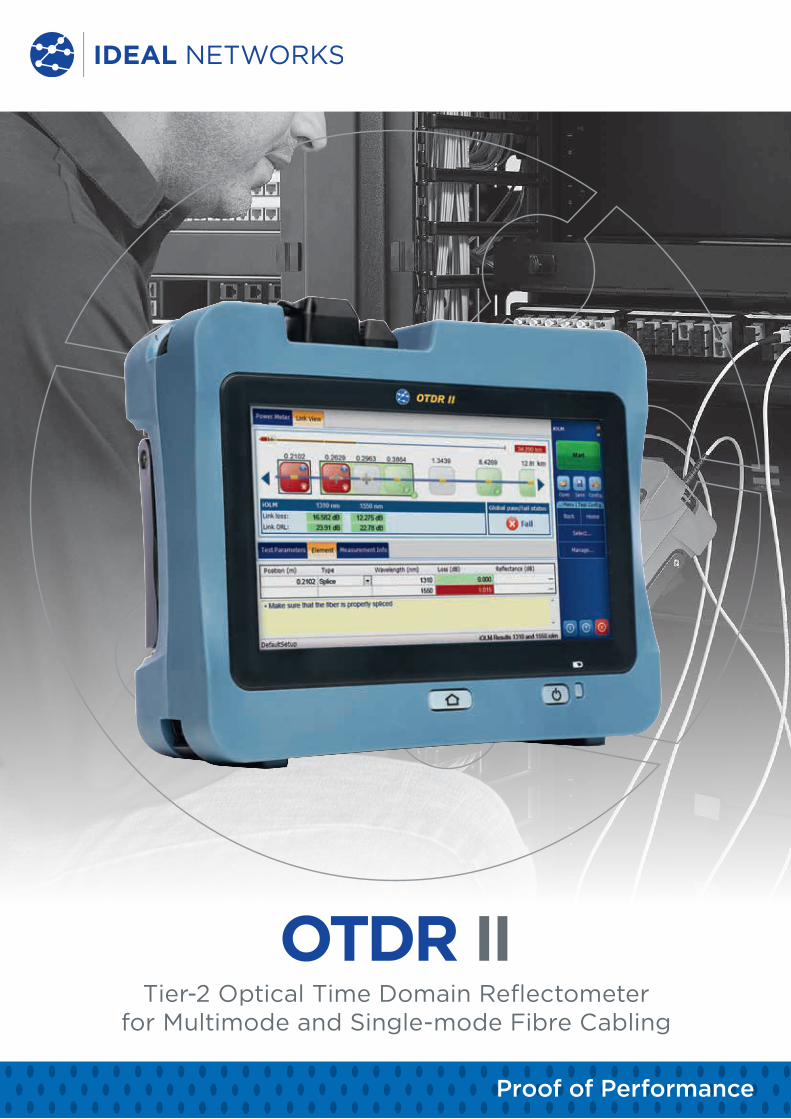
OTDR IITier-2 Optical Time Domain Reflectometer
for Multimode and Single-mode Fibre Cabling
Proof of Performance
www.idealnetworks.net
Tier-2 Optical Time Domain Reflectometer for Multimode and Single-mode Fibre Cabling
OTDR II The OTDR II is the first tablet inspired OTDR that is handy, lightweight
and rugged enough for any environment. With a 7-inch outdoor
enhanced touchscreen, the most efficient hand held display in the
industry, it delivers an unprecedented user experience. Its intuitive
user interface including onboard manual ensures a fast learning curve.
Plus, its new and improved OTDR platform offers icon-based functions,
instant boot-up, automatic macrobend finders as well as improved auto
and real-time modes.
The handheld OTDR... reinvented.The OTDR II is finally bringing the iOLM, an intelligent OTDR-based application, to the handheld market. This advanced software turns even the most complex trace analysis into a simple, one-touch task. The iOLM feature removes the need for analysis of complicated OTDR traces. However, the traces are available on the reports and PC software if required. For traditional OTDR users an OTDR II trace option is available to view and analyse traces on the tester.
The amazing 12-hour battery life will never let a technician down, and the plug-and-play hardware options, like the power meter and the USB video probe, make every technician’s job easier. Unlike traditional OTDRs, OTDR II does not require specific launch cords which makes testing more cost effective and user friendly.
The entry-level solution designed for all your testing needsThe OTDR II/iOLM features a dynamic range of 36 dB in single-mode and 29 dB in multimode, as well as industry-leading dead zones. This ensures efficient testing of closely spaced events such as patch cords in data centres, or patch panels in central offices (COs). The OTDR II is optimised for point-to-point testing of any access network, and is suitable for testing through 1x32 splitters.
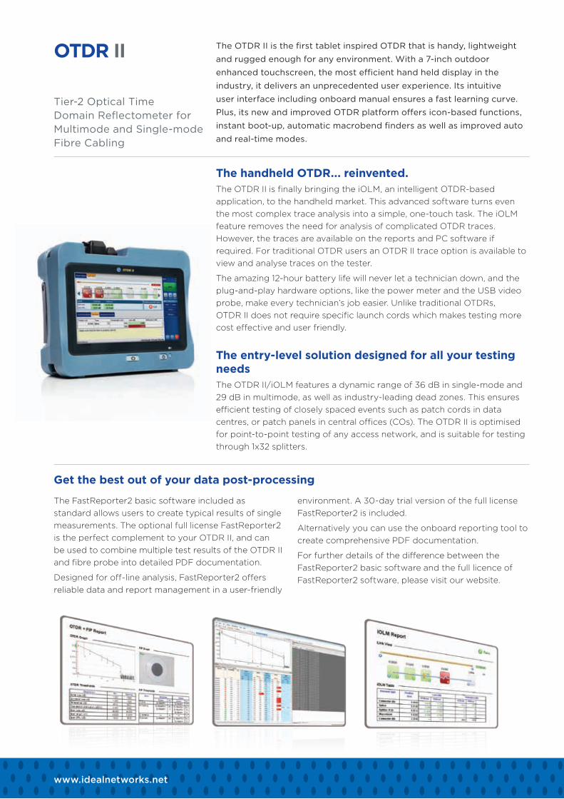
Get the best out of your data post-processing
The FastReporter2 basic software included as standard allows users to create typical results of single measurements. The optional full license FastReporter2 is the perfect complement to your OTDR II, and can be used to combine multiple test results of the OTDR II and fibre probe into detailed PDF documentation.
Designed for off-line analysis, FastReporter2 offers reliable data and report management in a user-friendly
environment. A 30-day trial version of the full license FastReporter2 is included.
Alternatively you can use the onboard reporting tool to create comprehensive PDF documentation.
For further details of the difference between the FastReporter2 basic software and the full licence of FastReporter2 software, please visit our website.
OTDR testing comes with many challenges...
In response to these challenges, IDEAL Networks is providing a better way to test fibre optics:
The intelligent Optical Link Mapper (iOLM) turns complicated graphs into an easy to read diagram displaying all events along the link with pass/fail status for each event. The iOLM is an OTDR-based application designed to simplify OTDR testing by eliminating the need to configure parameters, and/or analyse and interpret multiple complex OTDR traces. Its advanced algorithms dynamically define the testing parameters, as well as the number of acquisitions that best fit the network under test. By correlating multiple pulse widths on multiple wavelengths, the iOLM locates and identifies faults with maximum resolution – all at the push of a single button.
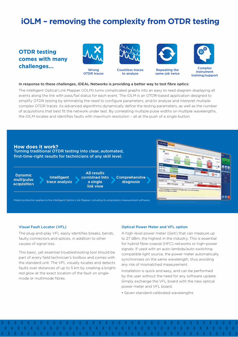
iOLM – removing the complexity from OTDR testing
How does it work?Turning traditional OTDR testing into clear, automated, first-time-right results for technicians of any skill level.
Dynamic multipulse acquisition
Intelligent trace analysis
All results combined into
a single link view
Comprehensive diagnosis
Patent protection applies to the intelligent Optical Link Mapper, including its proprietary measurement software.
Visual Fault Locator (VFL)
The plug-and-play VFL easily identifies breaks, bends, faulty connectors and splices, in addition to other causes of signal loss.
This basic, yet essential troubleshooting tool should be part of every field technician’s toolbox and comes with the standard unit. The VFL visually locates and detects faults over distances of up to 5 km by creating a bright-red glow at the exact location of the fault on single-mode or multimode fibres.
Optical Power Meter and VFL option
A high-level power meter (GeX) that can measure up to 27 dBm, the highest in the industry. This is essential for hybrid fibre-coaxial (HFC) networks or high-power signals. If used with an auto-lambda/auto-switching compatible light source, the power meter automatically synchronises on the same wavelength, thus avoiding any risk of mismatched measurement.
Installation is quick and easy, and can be performed by the user without the need for any software update. Simply exchange the VFL board with the new optical power meter and VFL board.
• Seven standard calibrated wavelengths
Wrong OTDR traces
Countless traces to analyse
Repeating the same job twice
Complex instrument
training/support
Proof of Performance
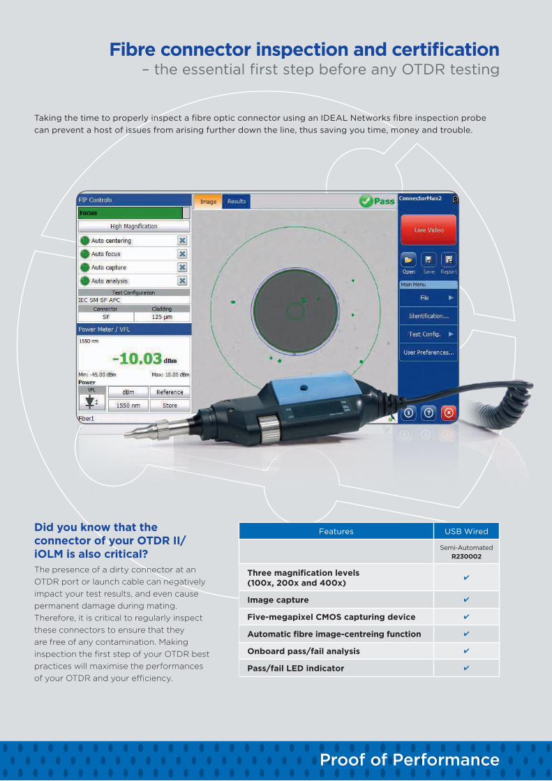
Taking the time to properly inspect a fibre optic connector using an IDEAL Networks fibre inspection probe can prevent a host of issues from arising further down the line, thus saving you time, money and trouble.
Fibre connector inspection and certification – the essential first step before any OTDR testing
Did you know that the connector of your OTDR II/iOLM is also critical?The presence of a dirty connector at an OTDR port or launch cable can negatively impact your test results, and even cause permanent damage during mating. Therefore, it is critical to regularly inspect these connectors to ensure that they are free of any contamination. Making inspection the first step of your OTDR best practices will maximise the performances of your OTDR and your efficiency.
Features USB Wired
Semi-Automated R230002
Three magnification levels(100x, 200x and 400x)
Image capture
Five-megapixel CMOS capturing device
Automatic fibre image-centreing function
Onboard pass/fail analysis
Pass/fail LED indicator
Proof of Performance
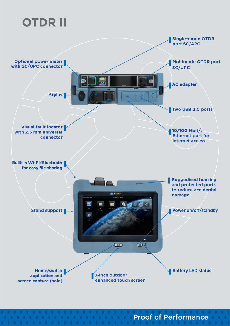
OTDR II
Optional power meter with SC/UPC connector
Stylus
Visual fault locator with 2.5 mm universal
connector
Multimode OTDR portSC/UPC
Single-mode OTDR port SC/APC
10/100 Mbit/s Ethernet port for internet access
Two USB 2.0 ports
AC adapter
Stand support
Built-in Wi-Fi/Bluetooth for easy file sharing
Power on/off/standby
Battery LED status
Ruggedised housing and protected ports to reduce accidental damage
7-inch outdoor enhanced touch screen
Home/switch application and
screen capture (hold)
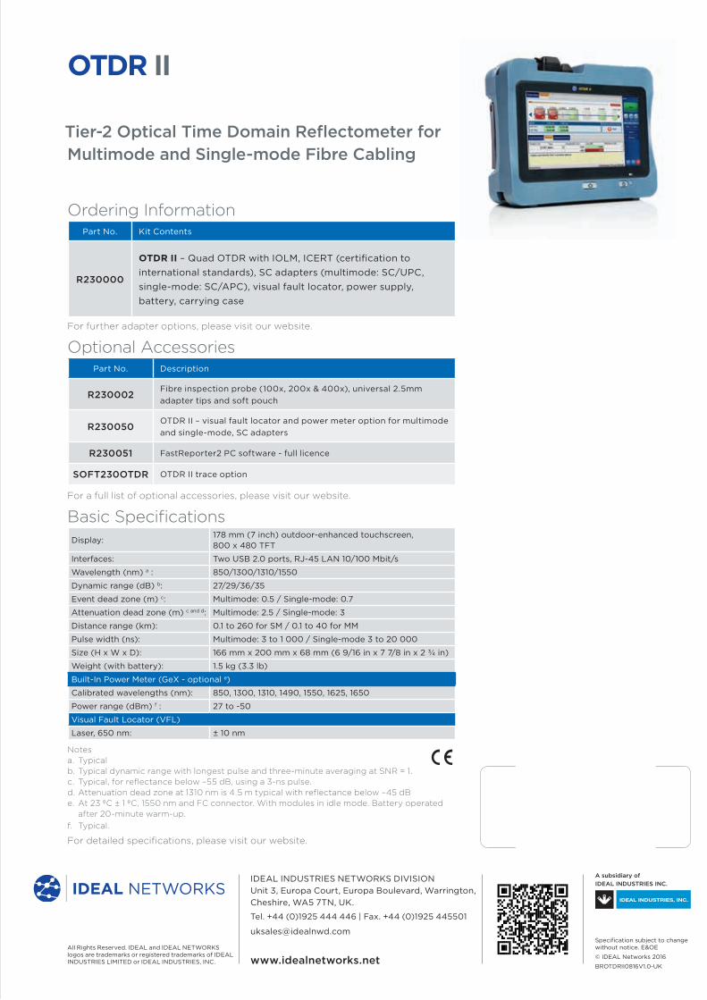
Ordering InformationPart No. Kit Contents
R230000
OTDR II – Quad OTDR with IOLM, ICERT (certification to international standards), SC adapters (multimode: SC/UPC, single-mode: SC/APC), visual fault locator, power supply, battery, carrying case
For further adapter options, please visit our website.
Optional AccessoriesPart No. Description
R230002Fibre inspection probe (100x, 200x & 400x), universal 2.5mm adapter tips and soft pouch
R230050OTDR II – visual fault locator and power meter option for multimode and single-mode, SC adapters
R230051 FastReporter2 PC software - full licence
SOFT230OTDR OTDR II trace option
For a full list of optional accessories, please visit our website.
Basic SpecificationsDisplay:
178 mm (7 inch) outdoor-enhanced touchscreen, 800 x 480 TFT
Interfaces: Two USB 2.0 ports, RJ-45 LAN 10/100 Mbit/s
Wavelength (nm) a : 850/1300/1310/1550
Dynamic range (dB) b: 27/29/36/35
Event dead zone (m) c: Multimode: 0.5 / Single-mode: 0.7
Attenuation dead zone (m) c and d: Multimode: 2.5 / Single-mode: 3
Distance range (km): 0.1 to 260 for SM / 0.1 to 40 for MM
Pulse width (ns): Multimode: 3 to 1 000 / Single-mode 3 to 20 000
Size (H x W x D): 166 mm x 200 mm x 68 mm (6 9/16 in x 7 7/8 in x 2 ¾ in)
Weight (with battery): 1.5 kg (3.3 lb)
Built-In Power Meter (GeX - optional e)
Calibrated wavelengths (nm): 850, 1300, 1310, 1490, 1550, 1625, 1650
Power range (dBm) f : 27 to -50
Visual Fault Locator (VFL)
Laser, 650 nm: ± 10 nm
Notesa. Typicalb. Typical dynamic range with longest pulse and three-minute averaging at SNR = 1.c. Typical, for reflectance below –55 dB, using a 3-ns pulse.d. Attenuation dead zone at 1310 nm is 4.5 m typical with reflectance below –45 dBe. At 23 ºC ± 1 ºC, 1550 nm and FC connector. With modules in idle mode. Battery operated
after 20-minute warm-up.f. Typical.
For detailed specifications, please visit our website.
Tier-2 Optical Time Domain Reflectometer for Multimode and Single-mode Fibre Cabling
OTDR II
All Rights Reserved. IDEAL and IDEAL NETWORKS logos are trademarks or registered trademarks of IDEAL INDUSTRIES LIMITED or IDEAL INDUSTRIES, INC.
IDEAL INDUSTRIES NETWORKS DIVISIONUnit 3, Europa Court, Europa Boulevard, Warrington, Cheshire, WA5 7TN, UK.
Tel. +44 (0)1925 444 446 | Fax. +44 (0)1925 445501
A subsidiary of IDEAL INDUSTRIES INC.
Specification subject to change without notice. E&OE
© IDEAL Networks 2016
BROTDRII0816V1.0-UKwww.idealnetworks.net